WO2009040699A1 - A method for classifying a transponder and/or signals originating from a transponder and reader - Google Patents
A method for classifying a transponder and/or signals originating from a transponder and reader Download PDFInfo
- Publication number
- WO2009040699A1 WO2009040699A1 PCT/IB2008/053730 IB2008053730W WO2009040699A1 WO 2009040699 A1 WO2009040699 A1 WO 2009040699A1 IB 2008053730 W IB2008053730 W IB 2008053730W WO 2009040699 A1 WO2009040699 A1 WO 2009040699A1
- Authority
- WO
- WIPO (PCT)
- Prior art keywords
- transponder
- response
- signal
- reader
- signals
- Prior art date
Links
Classifications
-
- G—PHYSICS
- G01—MEASURING; TESTING
- G01S—RADIO DIRECTION-FINDING; RADIO NAVIGATION; DETERMINING DISTANCE OR VELOCITY BY USE OF RADIO WAVES; LOCATING OR PRESENCE-DETECTING BY USE OF THE REFLECTION OR RERADIATION OF RADIO WAVES; ANALOGOUS ARRANGEMENTS USING OTHER WAVES
- G01S7/00—Details of systems according to groups G01S13/00, G01S15/00, G01S17/00
- G01S7/02—Details of systems according to groups G01S13/00, G01S15/00, G01S17/00 of systems according to group G01S13/00
- G01S7/41—Details of systems according to groups G01S13/00, G01S15/00, G01S17/00 of systems according to group G01S13/00 using analysis of echo signal for target characterisation; Target signature; Target cross-section
- G01S7/415—Identification of targets based on measurements of movement associated with the target
-
- G—PHYSICS
- G01—MEASURING; TESTING
- G01S—RADIO DIRECTION-FINDING; RADIO NAVIGATION; DETERMINING DISTANCE OR VELOCITY BY USE OF RADIO WAVES; LOCATING OR PRESENCE-DETECTING BY USE OF THE REFLECTION OR RERADIATION OF RADIO WAVES; ANALOGOUS ARRANGEMENTS USING OTHER WAVES
- G01S13/00—Systems using the reflection or reradiation of radio waves, e.g. radar systems; Analogous systems using reflection or reradiation of waves whose nature or wavelength is irrelevant or unspecified
- G01S13/74—Systems using reradiation of radio waves, e.g. secondary radar systems; Analogous systems
- G01S13/76—Systems using reradiation of radio waves, e.g. secondary radar systems; Analogous systems wherein pulse-type signals are transmitted
- G01S13/765—Systems using reradiation of radio waves, e.g. secondary radar systems; Analogous systems wherein pulse-type signals are transmitted with exchange of information between interrogator and responder
-
- G—PHYSICS
- G01—MEASURING; TESTING
- G01S—RADIO DIRECTION-FINDING; RADIO NAVIGATION; DETERMINING DISTANCE OR VELOCITY BY USE OF RADIO WAVES; LOCATING OR PRESENCE-DETECTING BY USE OF THE REFLECTION OR RERADIATION OF RADIO WAVES; ANALOGOUS ARRANGEMENTS USING OTHER WAVES
- G01S13/00—Systems using the reflection or reradiation of radio waves, e.g. radar systems; Analogous systems using reflection or reradiation of waves whose nature or wavelength is irrelevant or unspecified
- G01S13/02—Systems using reflection of radio waves, e.g. primary radar systems; Analogous systems
- G01S13/50—Systems of measurement based on relative movement of target
- G01S13/58—Velocity or trajectory determination systems; Sense-of-movement determination systems
- G01S13/588—Velocity or trajectory determination systems; Sense-of-movement determination systems deriving the velocity value from the range measurement
-
- G—PHYSICS
- G01—MEASURING; TESTING
- G01S—RADIO DIRECTION-FINDING; RADIO NAVIGATION; DETERMINING DISTANCE OR VELOCITY BY USE OF RADIO WAVES; LOCATING OR PRESENCE-DETECTING BY USE OF THE REFLECTION OR RERADIATION OF RADIO WAVES; ANALOGOUS ARRANGEMENTS USING OTHER WAVES
- G01S7/00—Details of systems according to groups G01S13/00, G01S15/00, G01S17/00
- G01S7/02—Details of systems according to groups G01S13/00, G01S15/00, G01S17/00 of systems according to group G01S13/00
- G01S7/28—Details of pulse systems
- G01S7/285—Receivers
- G01S7/288—Coherent receivers
- G01S7/2886—Coherent receivers using I/Q processing
Definitions
- the invention relates to a method for classifying a transponder and/or signals originating from a transponder and to a reader.
- Transponders which are also referred to as tags or labels, are well known in the art and are designed to communicate with a reader which is also known as a base station. Usually, the reader sends a signal to the transponder. If the transponder is close enough to the reader, then the transponder receives this signal and may send, in response to the received signal, a response signal to the reader.
- a plurality of goods each carrying a transponder is transported as a whole, for instance, on a pallet.
- a reader may detect the transponders.
- the reader or a further device only processes signals received from the transponders of the plurality of goods.
- the range, within the reader can communicate with transponders is relatively wide, then it may happen that the reader receives a response from a transponder not associated with the plurality of goods.
- Such transponder reader systems are, for instance, ultra high frequency (UHF) RFID transponder reader systems.
- Another object of the present invention is to provide a reader which is capable of differentiating between signals originating from transponders associated with the plurality of goods and signals originating from further transponders.
- the object is achieved in accordance with the invention by means of a method for classifying a transponder and/or signals originating from a transponder, comprising the steps of: receiving a signal from a transponder; determining the velocity with which the transponder is moving; and classifying the transponder and/or signals originating from the transponder as valid or invalid in response to the determined velocity.
- the inventive method is particularly beneficial when discriminating transponders which are moved with a plurality of goods from other transponders in a relatively short time and in particular by means of a ultra high frequency (UHF) transponder reader system with long radio range.
- UHF ultra high frequency
- determination of the velocity of a transponder can be used as a property to identify transponders moved with the goods.
- the related transponder and/or signals originating from this transponder can be classified as valid or invalid.
- only signals originating from a valid transponder may be used for further processing.
- the determined velocity can be used to cluster all the transponders having the same velocity to one group and specify it as a valid group of goods detected.
- Signals from transponders having different velocities for instance, originating from unwanted reads from adjacent doors or pallets standing nearby, can be clustered to another group and are specified as an invalid group of goods in, for instance, a registration (inventory) process.
- the inventive method further comprises classifying the transponder and/or signals originating from the transponder as valid if the determined velocity is above a first reference velocity and/or below a second reference velocity which is greater than the first reference velocity.
- the transponders to be detected are moving with a certain velocity. Classifying transponders and/or signals originating from the transponders as valid if the transponders move above the first reference velocity particularly allows to reject non-moving transponders, i.e. particularly allows classifying non-moving transponders and/or their signals as invalid.
- the first reference velocity is preferably chosen in order to reliably detecting transponders moving with the certain velocity.
- the velocity of the transponder can be determined with arbitrary means.
- the velocity is determined using signals sent by the transponder.
- the step of determining the velocity of the transponder comprises: sending from the reader a first signal to the transponder; receiving at the reader in response to the first signal a first response signal emitted by the transponder; sending from the reader a second signal to the transponder in response to the first response signal; receiving at the reader in response to the second signal a second response signal emitted by the transponder; and determining the velocity of the transponder based on the time interval between the received first and second response signals.
- a reader comprises a sender configured to generate and send first and second signals to a transponder, and a receiver configured to receive a first response signal from the transponder in response to the first signal and to receive a second response signal from the transponder in response to the second signal, wherein the reader is configured to determine the velocity of the transponder based on the time interval between receiving the first and second response signals and based on the received first and second response signals.
- the first signal sent from the reader may particularly be a query signal used to search for transponders. If the transponder is within the radio range of the reader, it receives the first signal and generates the first response signal.
- the first response signal may include a random number generated by and assigned to the transponder.
- the reader In response to the received first response signal, the reader generates and sends the second signal which may be an acknowledge signal.
- the transponder In response to the second signal, the transponder generates and sends the second response signal which may, for instance, include an electronic product code (EPC) of its associated product and also a cyclic redundancy checksum that may relate to the random number.
- EPC electronic product code
- the time interval between receiving the two response signals and analyzing the two response signals can be used to determine the velocity of the transponder.
- the first and second response signals may be demodulated at the reader utilizing a quadrature amplitude modulated scheme so that each de-modulated first and second response signal comprises first and second components being orthogonal to each other. Then determining the velocity may include estimating the phase-shift between the two response signals and the time interval between receiving the first and second response signals.
- the first and second response signals may be quadrature amplitude modulated signals each having the first and second components being orthogonal to each other. This, however, is not necessary.
- the transponder may also send the receiving signals utilizing, for instance, an ASK or a PSK/BPSK modulation scheme.
- phase-shift or angle, ⁇ between the two response signals can, for instance, be estimated as following:
- arctan2 (5 e (t 2 ), S 1 (t 2 )) - arctan2(5g ( ⁇ 1 ), S 1 (t ⁇ ))
- Si(ti) is the first component of the first response signal
- S Q (I I ) is the second component of the first response signal
- Sifo) is the first component of the second response signal
- S ⁇ fo is the second component of the second response signal
- arctan2 is the four quadrant inverse tangent function of the parts of the elements of S Q and Si .
- the velocity, v, of the transponder may be estimated according to the following equation:
- ⁇ is the angular carrier frequency of a carrier signal for the first and second response signals
- v p is the propagation velocity of the carrier signal
- ⁇ - t is the time interval between receiving the first and second response signals
- At least one of the first or second components of the first or second response signals may be averaged over time.
- Quadrature amplitude modulation is known in the art per se and is a modulation scheme which conveys data by modulating the amplitude of two carrier waves.
- the two carrier waves are phase-shifted with respect to each other by 90° and have the same angular carrier frequency CO.
- the flow of bits to be transmitted is split into two parts, resulting in the generation of two independent signals to be transmitted (channels).
- the two independent signals are encoded separately utilizing, for instance, amplitude shift keying (ASK) or phase shift keying (PSK) modulation.
- ASK amplitude shift keying
- PSK phase shift keying
- One of the encoded signals is modulated by a cosine ("in-phase channel” or “I-channel”) and the other encoded signal is modulated by a sine ("quadrature channel” or “Q-channel”). Then, the two signals are added one to the other and sent through a real channel.
- the first and second components can be described using the following equations, if the first component is "in- phase” and the second component of the second component is "quadrature":
- d is the distance form the reader to the transponder
- COm is the angular modulation frequency of the fundamental wave (link)
- ⁇ is the unknown phase shift with respect to the carrier signal
- v p is the propagation velocity in the related medium.
- the related medium is usually air.
- the first terms of the two components Si, S Q are time independent and can be treated as an additional amplitude modulation dependent on distance and wave-length.
- the perpendicular nature of the orthogonal IQ-channels prevents the cancellation of the base-band information in all conditions of distance and wavelength.
- the additional amplitude modulation can be useful for target tracking and target velocity estimation and can help to estimate the material properties, because different materials in which the medium propagates cause different propagation velocities.
- two or more synchronized readers or one reader with specially distributed receiving antennas can be utilized for triangulation in order to achieve better localization conditions.
- the velocity, v, of the transponder can be estimated as:
- Ad is the distance the transponder has moved between receiving the two response signals.
- the signals Si and S Q may be averaged to eliminate the time dependent components.
- the maximum allowed velocity of the transponder may be calculated. If using, for instance, an ultra high frequency (UHF) reader transponder system operating in accordance with the EPCglobal UHF Protocol Standard, then the system may currently operate in the range of IGHz. The time between receiving the two response signals in the case of the random number assigned to the transponder is currently in the range of 2 ms. Thus, the maximum velocity, v max , of the transponder and assuming the propagation medium is air, is approximately:
- the inventive method and the inventive reader can particularly be used, utilizing the transportation velocity of tags or transponders, as a distinctive feature for classification and detection of tags belonging to a group which is moved with the same velocity. Furthermore, the classification may be used to separate valid reads and invalid (unwanted) reads of the transponders.
- Fig. 1 is an RFID reader transponder system
- Fig. 2 is a circuit diagram of a part of the reader of Fig. 1, and Fig. 3 illustrates signals received by the reader.
- Fig. 1 shows an RFID transponder reader system.
- the transponder reader system operates in accordance with the EPCglobal UHF Protocol Standard and can communicate with each other based on zero intermediate frequency and quadrature amplitude de-modulation (QAM).
- QAM quadrature amplitude de-modulation
- the transponder 1 is placed apart from the reader 20 at a distance d, is attached on a product not explicitly shown in the figures and is moving with the product at a velocity v.
- the transponder 1 comprises a substrate 2, an electric circuit which is an integrated circuit 3 for the exemplary embodiment, and an antenna 4.
- the integrated circuit 3 and the antenna 4 are attached to the substrate 2.
- the transponder 1 is configured to receive signals sent by the reader 20 and to generate and send response signals in response to the signals of the reader 20.
- the response signals are ASK, PSK, BPSK or QAM signals in this embodiment and may have two components being orthogonal to each other in QAM and one component in ASK, PSK, and BPSK. Each component is modulated utilizing an ASK modulation scheme.
- the generation of the response signals is known per se in the art and is thus not explained in detail.
- the integrated circuit 3 of the transponder 1 may, for instance, comprise a memory 6 which stores the content of the response signal, and a microcontroller 5 connected to the memory 6 to generate the response signals.
- signals of the reader 20 are transmitted utilizing an UHF electro -magnetic field, as it is known per se in the art.
- the integrated circuit 3 further comprises a decoder/ encoder stage 7 which is connected to the micro-controller 5 and to the antenna 4.
- the decoder/ encoder stage 7 is configured to process the output signals of the antenna 4 in order to decode the reader signals from the electro -magnetic field.
- the decoded signals are then transferred to the micro-controller 5 for further processing.
- a clock signal needed for processing of the decoded signals is derived from the electro -magnetic field.
- the transponder 1 is a passive transponder whose integrated circuit 3 is powered by the electro-magnetic field emitted by the reader 20.
- the transponder 1 can also be an active transponder.
- the reader 20 comprises antennas 22, an electric circuit 21 which comprises a sender 23 and a receiver 24, and a multiplexer 29 to select an appropriate antenna of the antennas 22 when being in its sending or receiving mode.
- the sender 23 is configured to generate signals, in particular first and second signals 25, 26 directed to the transponder 1.
- Fig. 2 shows the electric circuit 21 of the reader 20 more detailed.
- the electric circuit 21 comprises, besides the sender 23 and the receiver 24, a cosine wave signal generator 43 which generates a signal used as the power carrier for the electro-magnetic wave and having a carrier frequency,/, of 915 MHz, and a circulator 44.
- a circulator is a directional isolator and directional router dependent on the direction of outgoing and incoming signals at its individual ports.
- the signal generator 43 may be tunable and is connected to the sender 23 and to the receiver 24.
- the circulator 44 is connected to the outputs of the sender 23 and the receiver 24 and is also connected to the multiplexer 29.
- a multiplexer 29 is a device that switches the antennas 22 alternatively between the sender 23 and the receiver 24.
- the carrier frequency,/ may be fixed or variable and is not restricted to 915 MHz.
- the sender 23 comprises a buffer 42, a mixer 40 and a power amplifier 41.
- the buffer 42 is connected to the signal generator 43 and to the mixer 40.
- the mixer 40 modulates data on the carrier signal generated by the signal generator 43.
- the modulated signal is passed to the power amplifier 41 which is connected to the circulator 44.
- the output signal of the power amplifier 41 is transmitted by the antennas 22 to the transponder 1.
- the modulation scheme used for the sender 23 is ASK or PR-ASK.
- the receiver 24 comprises a splitter 31 , first and second mixers 32, 33, first and second image rejection filters 34, 35, a buffer 39, a phase- shifter 38, a microprocessor 36, and a memory 37 connected to the microprocessor 36.
- the image rejection filters 34, 35 are essentially identical and comprise each electro -magnetic interference (EMI) low-pass filters 34c, 35c, high-pass filters 34b, 35b, and programmable fifth order low-pass filters 34a, 35a.
- EMI electro -magnetic interference
- the buffer 39 is connected to the signal generator 43 and the phase-shifter 38 phase-shifts an input signal by 90°.
- the reader 20 When the reader 20 receives an ASK, PSK, BPSK or QAM signal, then this signal is captured by the antenna 22 and fed via the circulator 44 to the splitter 31.
- the splitter 31 basically splits this signal into two identical signals. One of the split signals is fed to the first mixer 32 and the other split signal is fed to the second mixer 33.
- the first mixer 32 is connected to the signal generator 43 via the buffer 39.
- the second mixer 33 is connected to the phase-shifter 38 which is connected to the signal generator 43 via the buffer 39. Therefore, the input signals for the first mixer 32 are signals received by the reader 20 and a cosine signal having the angular carrier frequency, CO, and the input signals to the second mixer 33 are signals received by the reader 20 and a sine signal having the angular carrier frequency, CO.
- the output signals of the mixers 32, 33 are thus orthogonal to each other and are passed through the image rejection filters 34, 35 and processed by the microprocessor 36.
- the receiver 24 does not utilize any intermediate frequency for the exemplary embodiment
- the reader 20 When initiating a communication, the reader 20 generates and sends the first signal 25 which is a query signal for the exemplary embodiment.
- the transponder 1 In response to the first signals 25, the transponder 1 generates a first response signal 27 utilizing backscattering as it is known per se in the art and sends it to the reader 20.
- the first response signal 27 is an ASK, PSK, BPSK or QAM signal which is based on zero intermediate frequency.
- the first response signal 27 may comprises a random number generated by and assigned to the transponder 1.
- the reader 20 receives the first response signal 27, it records the present time, ti, demodulates the first response signal utilizing its mixers 32, 33, and generates and sends the second signal 26 which is an acknowledge signed for the exemplary embodiment.
- the transponder 1 Upon receiving the second signal 26, the transponder 1 demodulates and processes the second signal 26, and generates and sends a second response signal 28.
- the second response signal 28 includes an electronic product code (EPC) of its associated product and also a cyclic redundancy checksum related to the random number.
- EPC electronic product code
- the reader 20 When the reader 20 receives the second response signal 28, it records the present time, t2, demodulates the second response signal utilizing its mixers 32, 33, and processes the information of the second response signal 28.
- the de-modulated first and second response signals 27, 28 have each two components Si, S Q , which can be described using the following equations, if the first component Si is "in-phase” and the second component S Q is "quadrature":
- d is the distance form the reader 20 to the transponder 1
- COm is the modulation angular frequency of the fundamental wave (link)
- ⁇ is the unknown phase shift with respect to the carrier signal having the angular frequency CO
- v p is the propagation velocity in the related medium which is air for the exemplary embodiment.
- Fig. 3 illustrates the two response signals 27, 28 in the IQ-plane. Effects of amplitude variations of the response signals 27, 28 can be reduced by averaging the signals for estimation of the transponder 1 velocity v. The difference of the phase shifts with respect to the carrier signal for the first and second response signals 27, 28 is illustrated by an angle (phase-shift) ⁇ .
- the angle ⁇ can be estimated as:
- the microprocessor 36 compares the determined velocity v of the transponder 1 with a reference velocity and classifies the second response signal 28 only as valid, if the estimated velocity v of the transponder 1 is greater than the reference velocity. Otherwise, the microprocessor 36 classifies the second response signal 28 as invalid.
- the time instances ti, t2 at which the reader 20 receives the two response signals 27, 28 are stored, for instance, in the memory 37. Alternatively, it is possible to only determine the difference between these two time instances by, for instance, starting a counter at the time instance tj.
Abstract
The invention discloses a method for classifying a transponder (1) and/or signals originating from a transponder (1) and a reader (20) for the inventive method. According to the invention, a reader (20) receives a signal (27, 28) from the transponder (1) and determines the the velocity (v), with which the transponder (1) is moving. Finally, the transponder (1) and/or signals (28) originating from the transponder (1) are classified as valid or invalid in response to the determined velocity (v).
Description
A method for classifying a transponder and/or signals originating from a transponder and reader
FIELD OF THE INVENTION
The invention relates to a method for classifying a transponder and/or signals originating from a transponder and to a reader.
BACKGROUND OF THE INVENTION
Transponders, which are also referred to as tags or labels, are well known in the art and are designed to communicate with a reader which is also known as a base station. Usually, the reader sends a signal to the transponder. If the transponder is close enough to the reader, then the transponder receives this signal and may send, in response to the received signal, a response signal to the reader.
In some applications, a plurality of goods each carrying a transponder is transported as a whole, for instance, on a pallet. When passing a certain point, for instance, a door or a gate, a reader may detect the transponders. In this scenario, it is desired that the reader or a further device only processes signals received from the transponders of the plurality of goods. Particularly, if the range, within the reader can communicate with transponders, is relatively wide, then it may happen that the reader receives a response from a transponder not associated with the plurality of goods. Such transponder reader systems are, for instance, ultra high frequency (UHF) RFID transponder reader systems.
OBJECT AND SUMMARY OF THE INVENTION
It is an object of the present invention to provide a method which allows to differentiate between signals originating from transponders associated with the plurality of goods and signals originating from further transponders.
Another object of the present invention is to provide a reader which is capable of differentiating between signals originating from transponders associated with the plurality of goods and signals originating from further transponders.
The object is achieved in accordance with the invention by means of a method for classifying a transponder and/or signals originating from a transponder, comprising the steps of:
receiving a signal from a transponder; determining the velocity with which the transponder is moving; and classifying the transponder and/or signals originating from the transponder as valid or invalid in response to the determined velocity. The inventive method is particularly beneficial when discriminating transponders which are moved with a plurality of goods from other transponders in a relatively short time and in particular by means of a ultra high frequency (UHF) transponder reader system with long radio range. As the transponders associated with the moving goods (e.g. on a pallet) have all the same velocity, determination of the velocity of a transponder can be used as a property to identify transponders moved with the goods. In response to the identification based on the determined velocity, the related transponder and/or signals originating from this transponder can be classified as valid or invalid. Then, for instance, only signals originating from a valid transponder may be used for further processing. As a result, the determined velocity can be used to cluster all the transponders having the same velocity to one group and specify it as a valid group of goods detected. Signals from transponders having different velocities, for instance, originating from unwanted reads from adjacent doors or pallets standing nearby, can be clustered to another group and are specified as an invalid group of goods in, for instance, a registration (inventory) process.
In one embodiment, the inventive method further comprises classifying the transponder and/or signals originating from the transponder as valid if the determined velocity is above a first reference velocity and/or below a second reference velocity which is greater than the first reference velocity. The transponders to be detected are moving with a certain velocity. Classifying transponders and/or signals originating from the transponders as valid if the transponders move above the first reference velocity particularly allows to reject non-moving transponders, i.e. particularly allows classifying non-moving transponders and/or their signals as invalid. The first reference velocity is preferably chosen in order to reliably detecting transponders moving with the certain velocity.
Generally, the velocity of the transponder can be determined with arbitrary means. Preferably, the velocity is determined using signals sent by the transponder. In one embodiment of the inventive method, the step of determining the velocity of the transponder comprises: sending from the reader a first signal to the transponder; receiving at the reader in response to the first signal a first response signal emitted by the transponder; sending from the reader a second signal to the transponder in response to the first
response signal; receiving at the reader in response to the second signal a second response signal emitted by the transponder; and determining the velocity of the transponder based on the time interval between the received first and second response signals.
Thus, in a further aspect of the invention, a reader comprises a sender configured to generate and send first and second signals to a transponder, and a receiver configured to receive a first response signal from the transponder in response to the first signal and to receive a second response signal from the transponder in response to the second signal, wherein the reader is configured to determine the velocity of the transponder based on the time interval between receiving the first and second response signals and based on the received first and second response signals.
The first signal sent from the reader may particularly be a query signal used to search for transponders. If the transponder is within the radio range of the reader, it receives the first signal and generates the first response signal. The first response signal may include a random number generated by and assigned to the transponder. In response to the received first response signal, the reader generates and sends the second signal which may be an acknowledge signal. In response to the second signal, the transponder generates and sends the second response signal which may, for instance, include an electronic product code (EPC) of its associated product and also a cyclic redundancy checksum that may relate to the random number. The time interval between receiving the two response signals and analyzing the two response signals can be used to determine the velocity of the transponder. The first and second response signals may be demodulated at the reader utilizing a quadrature amplitude modulated scheme so that each de-modulated first and second response signal comprises first and second components being orthogonal to each other. Then determining the velocity may include estimating the phase-shift between the two response signals and the time interval between receiving the first and second response signals.
The first and second response signals may be quadrature amplitude modulated signals each having the first and second components being orthogonal to each other. This, however, is not necessary. The transponder may also send the receiving signals utilizing, for instance, an ASK or a PSK/BPSK modulation scheme.
The phase-shift or angle, φ , between the two response signals can, for instance, be estimated as following:
φ = arctan2(5e (t2 ), S1 (t2 )) - arctan2(5g (^1 ), S1 (tγ ))
wherein Si(ti) is the first component of the first response signal, SQ(II) is the second component of the first response signal, Sifo) is the first component of the second response signal, Sρfo) is the second component of the second response signal, and arctan2 is the four quadrant inverse tangent function of the parts of the elements of SQ and Si .
Then, the velocity, v, of the transponder may be estimated according to the following equation:
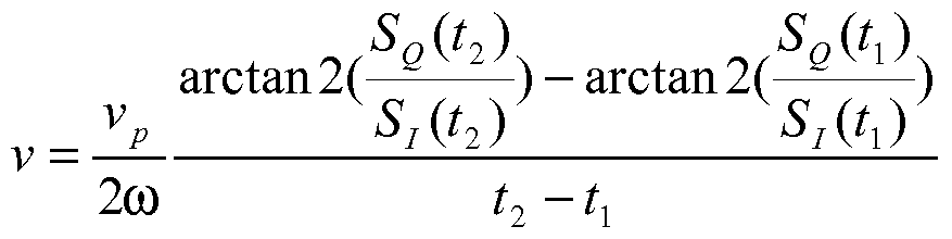
wherein ω is the angular carrier frequency of a carrier signal for the first and second response signals, vp is the propagation velocity of the carrier signal, and ^ - t; is the time interval between receiving the first and second response signals.
In order to improve the estimation of the velocity, at least one of the first or second components of the first or second response signals may be averaged over time.
Quadrature amplitude modulation, usually abbreviated as QAM, is known in the art per se and is a modulation scheme which conveys data by modulating the amplitude of two carrier waves. The two carrier waves are phase-shifted with respect to each other by 90° and have the same angular carrier frequency CO. Usually, the flow of bits to be transmitted is split into two parts, resulting in the generation of two independent signals to be transmitted (channels). The two independent signals are encoded separately utilizing, for instance, amplitude shift keying (ASK) or phase shift keying (PSK) modulation. One of the encoded signals is modulated by a cosine ("in-phase channel" or "I-channel") and the other encoded signal is modulated by a sine ("quadrature channel" or "Q-channel"). Then, the two signals are added one to the other and sent through a real channel.
When utilizing a zero intermediate frequency de-modulation scheme, particularly a zero intermediate quadrature amplitude modulation scheme, then the first and second components can be described using the following equations, if the first component is "in- phase" and the second component of the second component is "quadrature":
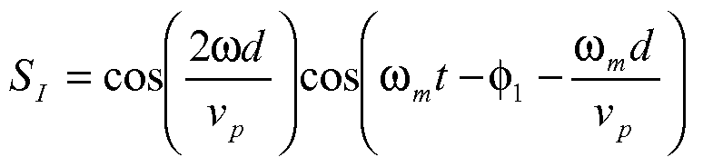

wherein d is the distance form the reader to the transponder, COm is the angular modulation frequency of the fundamental wave (link), φ; is the unknown phase shift with respect to the carrier signal, and vp is the propagation velocity in the related medium. The related medium is usually air. The first terms of the two components Si, SQ are time independent and can be treated as an additional amplitude modulation dependent on distance and wave-length. The perpendicular nature of the orthogonal IQ-channels prevents the cancellation of the base-band information in all conditions of distance and wavelength. The additional amplitude modulation can be useful for target tracking and target velocity estimation and can help to estimate the material properties, because different materials in which the medium propagates cause different propagation velocities. Furthermore, two or more synchronized readers or one reader with specially distributed receiving antennas can be utilized for triangulation in order to achieve better localization conditions.
Since the reader knows the time instances when it receives the two response signals, the velocity, v, of the transponder can be estimated as:

Ad is the distance the transponder has moved between receiving the two response signals.
The signals Si and SQ may be averaged to eliminate the time dependent components.
Since circular with 2π, the maximum allowed velocity of the
 transponder may be calculated. If using, for instance, an ultra high frequency (UHF) reader transponder system operating in accordance with the EPCglobal UHF Protocol Standard, then the system may currently operate in the range of IGHz. The time between receiving the two response signals in the case of the random number assigned to the transponder is currently in
the range of 2 ms. Thus, the maximum velocity, vmax, of the transponder and assuming the propagation medium is air, is approximately:
transponder may be calculated. If using, for instance, an ultra high frequency (UHF) reader transponder system operating in accordance with the EPCglobal UHF Protocol Standard, then the system may currently operate in the range of IGHz. The time between receiving the two response signals in the case of the random number assigned to the transponder is currently in
the range of 2 ms. Thus, the maximum velocity, vmax, of the transponder and assuming the propagation medium is air, is approximately:
2ωAd Ad 1 2π vp = 2π → vmax = — = = 75m / s v_ Δ* At 2ω
The inventive method and the inventive reader can particularly be used, utilizing the transportation velocity of tags or transponders, as a distinctive feature for classification and detection of tags belonging to a group which is moved with the same velocity. Furthermore, the classification may be used to separate valid reads and invalid (unwanted) reads of the transponders.
BRIEF DESCRIPTION OF THE DRAWINGS
The invention will be described in greater detail hereinafter, by way of non- limiting examples, with reference to the embodiments shown in the drawings. Fig. 1 is an RFID reader transponder system,
Fig. 2 is a circuit diagram of a part of the reader of Fig. 1, and Fig. 3 illustrates signals received by the reader.
DESCRIPTION OF EMBODIMENTS Fig. 1 shows an RFID transponder reader system. For the exemplary embodiment, the transponder reader system operates in accordance with the EPCglobal UHF Protocol Standard and can communicate with each other based on zero intermediate frequency and quadrature amplitude de-modulation (QAM).
For the exemplary embodiment, the transponder 1 is placed apart from the reader 20 at a distance d, is attached on a product not explicitly shown in the figures and is moving with the product at a velocity v. The transponder 1 comprises a substrate 2, an electric circuit which is an integrated circuit 3 for the exemplary embodiment, and an antenna 4. The integrated circuit 3 and the antenna 4 are attached to the substrate 2.
The transponder 1 is configured to receive signals sent by the reader 20 and to generate and send response signals in response to the signals of the reader 20. The response signals are ASK, PSK, BPSK or QAM signals in this embodiment and may have two components being orthogonal to each other in QAM and one component in ASK, PSK, and BPSK. Each component is modulated utilizing an ASK modulation scheme. The generation of the response signals is known per se in the art and is thus not explained in detail. In order
to generate the response signals, the integrated circuit 3 of the transponder 1 may, for instance, comprise a memory 6 which stores the content of the response signal, and a microcontroller 5 connected to the memory 6 to generate the response signals.
For the exemplary embodiment, signals of the reader 20 are transmitted utilizing an UHF electro -magnetic field, as it is known per se in the art. The integrated circuit 3 further comprises a decoder/ encoder stage 7 which is connected to the micro-controller 5 and to the antenna 4. The decoder/ encoder stage 7 is configured to process the output signals of the antenna 4 in order to decode the reader signals from the electro -magnetic field. The decoded signals are then transferred to the micro-controller 5 for further processing. A clock signal needed for processing of the decoded signals is derived from the electro -magnetic field.
For the exemplary embodiment, the transponder 1 is a passive transponder whose integrated circuit 3 is powered by the electro-magnetic field emitted by the reader 20. However, the transponder 1 can also be an active transponder. In this embodiment, the reader 20 comprises antennas 22, an electric circuit 21 which comprises a sender 23 and a receiver 24, and a multiplexer 29 to select an appropriate antenna of the antennas 22 when being in its sending or receiving mode. The sender 23 is configured to generate signals, in particular first and second signals 25, 26 directed to the transponder 1. Fig. 2 shows the electric circuit 21 of the reader 20 more detailed.
For the exemplary embodiment, the electric circuit 21 comprises, besides the sender 23 and the receiver 24, a cosine wave signal generator 43 which generates a signal used as the power carrier for the electro-magnetic wave and having a carrier frequency,/, of 915 MHz, and a circulator 44. A circulator is a directional isolator and directional router dependent on the direction of outgoing and incoming signals at its individual ports. The signal generator 43 may be tunable and is connected to the sender 23 and to the receiver 24. The circulator 44 is connected to the outputs of the sender 23 and the receiver 24 and is also connected to the multiplexer 29. A multiplexer 29 is a device that switches the antennas 22 alternatively between the sender 23 and the receiver 24. The carrier frequency,/, may be fixed or variable and is not restricted to 915 MHz.
In this embodiment, the sender 23 comprises a buffer 42, a mixer 40 and a power amplifier 41. The buffer 42 is connected to the signal generator 43 and to the mixer 40. The mixer 40 modulates data on the carrier signal generated by the signal generator 43. The modulated signal is passed to the power amplifier 41 which is connected to the circulator 44. The output signal of the power amplifier 41 is transmitted by the antennas 22 to the
transponder 1. For the exemplary embodiment, the modulation scheme used for the sender 23 is ASK or PR-ASK.
For the exemplary embodiment, the receiver 24 comprises a splitter 31 , first and second mixers 32, 33, first and second image rejection filters 34, 35, a buffer 39, a phase- shifter 38, a microprocessor 36, and a memory 37 connected to the microprocessor 36. The image rejection filters 34, 35 are essentially identical and comprise each electro -magnetic interference (EMI) low-pass filters 34c, 35c, high-pass filters 34b, 35b, and programmable fifth order low-pass filters 34a, 35a. The buffer 39 is connected to the signal generator 43 and the phase-shifter 38 phase-shifts an input signal by 90°. When the reader 20 receives an ASK, PSK, BPSK or QAM signal, then this signal is captured by the antenna 22 and fed via the circulator 44 to the splitter 31. The splitter 31 basically splits this signal into two identical signals. One of the split signals is fed to the first mixer 32 and the other split signal is fed to the second mixer 33. The first mixer 32 is connected to the signal generator 43 via the buffer 39. The second mixer 33 is connected to the phase-shifter 38 which is connected to the signal generator 43 via the buffer 39. Therefore, the input signals for the first mixer 32 are signals received by the reader 20 and a cosine signal having the angular carrier frequency, CO, and the input signals to the second mixer 33 are signals received by the reader 20 and a sine signal having the angular carrier frequency, CO. The output signals of the mixers 32, 33 are thus orthogonal to each other and are passed through the image rejection filters 34, 35 and processed by the microprocessor 36. The receiver 24 does not utilize any intermediate frequency for the exemplary embodiment.
When initiating a communication, the reader 20 generates and sends the first signal 25 which is a query signal for the exemplary embodiment. In response to the first signals 25, the transponder 1 generates a first response signal 27 utilizing backscattering as it is known per se in the art and sends it to the reader 20. The first response signal 27 is an ASK, PSK, BPSK or QAM signal which is based on zero intermediate frequency. The first response signal 27 may comprises a random number generated by and assigned to the transponder 1. When the reader 20 receives the first response signal 27, it records the present time, ti, demodulates the first response signal utilizing its mixers 32, 33, and generates and sends the second signal 26 which is an acknowledge signed for the exemplary embodiment.
Upon receiving the second signal 26, the transponder 1 demodulates and processes the second signal 26, and generates and sends a second response signal 28. For the exemplary embodiment, the second response signal 28 includes an electronic product code
(EPC) of its associated product and also a cyclic redundancy checksum related to the random number.
When the reader 20 receives the second response signal 28, it records the present time, t2, demodulates the second response signal utilizing its mixers 32, 33, and processes the information of the second response signal 28.
Since for the exemplary embodiment a zero intermediate frequency quadrature amplitude de-modulation scheme is used, the de-modulated first and second response signals 27, 28 have each two components Si, SQ, which can be described using the following equations, if the first component Si is "in-phase" and the second component SQ is "quadrature":

wherein d is the distance form the reader 20 to the transponder 1 , COm is the modulation angular frequency of the fundamental wave (link), φ; is the unknown phase shift with respect to the carrier signal having the angular frequency CO, and vp is the propagation velocity in the related medium which is air for the exemplary embodiment.
Since the transponder 1 is moving with the velocity v, the phase shift with respect to the carrier signal differs for the first and second response signals 27, 28. In order to determine the velocity v of the transponder 1, its velocity v is estimated according to the following equation:

Fig. 3 illustrates the two response signals 27, 28 in the IQ-plane. Effects of amplitude variations of the response signals 27, 28 can be reduced by averaging the signals for estimation of the transponder 1 velocity v. The difference of the phase shifts with respect to the carrier signal for the first and second response signals 27, 28 is illustrated by an angle
(phase-shift) φ. The angle φ can be estimated as:
SJt2) SJt1) φ = arctan2( ) - arctan2( )
For the exemplary embodiment, the microprocessor 36 compares the determined velocity v of the transponder 1 with a reference velocity and classifies the second response signal 28 only as valid, if the estimated velocity v of the transponder 1 is greater than the reference velocity. Otherwise, the microprocessor 36 classifies the second response signal 28 as invalid. For the exemplary embodiment, the time instances ti, t2 at which the reader 20 receives the two response signals 27, 28 are stored, for instance, in the memory 37. Alternatively, it is possible to only determine the difference between these two time instances by, for instance, starting a counter at the time instance tj.
Finally, it should be noted that the aforementioned embodiments illustrate rather than limit the invention, and that those skilled in the art will be capable of designing many alternative embodiments without departing from the scope of the invention as defined by the appended claims. In the claims, any reference signs placed in parentheses shall not be construed as limiting the claims. The word "comprise" and its conjugations do not exclude the presence of elements or steps other than those listed in any claim or the specification as a whole. The singular reference of an element does not exclude the plural reference of such elements and vice- versa. In a device claim enumerating several means, several of these means may be embodied by one and the same item of software or hardware. The mere fact that certain measures are recited in mutually different dependent claims does not indicate that a combination of these measures cannot be used to advantage.
Claims
1. A method for classifying a transponder and/or signals originating from a transponder, comprising the steps of: receiving at a reader (20) a signal (27, 28) from a transponder (1); determining the velocity (v) with which the transponder (1) is moving; and classifying the transponder (1) and/or signals (28) originating from the transponder (1) as valid or invalid in response to the determined velocity (v).
2. The method of claim 1, comprising classifying the transponder (1) and/or signals (28) originating from the transponder (1) as valid if the velocity (v) of the transponder (1) is above a first reference velocity and/or below a second reference velocity which is greater than the first reference velocity.
3. The method of claim 1 , wherein the step of determining the velocity (v) of the transponder (1) comprises: sending from the reader (20) a first signal (25) to the transponder (1); receiving at the reader (20) in response to the first signal (25) a first response signal (27) emitted by the transponder (1); sending from the reader (20) a second signal (26) to the transponder (1) in response to the first response signal (27); receiving at the reader (20) in response to the second signal (26) a second response signal (28) emitted by the transponder (1); and determining the velocity (v) of the transponder (1) based on the time interval between the received first and second response signals (27, 28).
4. The method of claim 3, comprising de-modulating the first and second response signals (27, 28) at the reader (20) utilizing a quadrature amplitude modulated scheme so that each de-modulated first and second response signal comprises first and second components being orthogonal to each other, and wherein determining the velocity (v) includes estimating the phase-shift (φ) between the two response signals (27, 28) and the time interval between receiving the first and second response signals (27, 28).
5. The method of claim 4, comprising determining the velocity (v) of the transponder (1) according to the following equation:

wherein v is the velocity (v) of the transponder (1), ω is the angular carrier frequency of a carrier signal for the first and second response signals (27, 28), vp is the propagation velocity of the carrier signal, ^ - t; is the time interval between receiving the first and second response signals (27, 28), Si(ti) is the first component of the first response signal (27), SQ(II) is the second component of the first response signal (27), Si(t2) is the first component of the second response signal (28), and SQ^) is the second component of the second response signal (28).
6. The method of claim 4, wherein at least one of the first or second components of the first or second response signals (27, 28) is averaged over time, and/or the modulation of the first and second response signals (27, 28) are based on zero intermediate frequency.
7. A reader, comprising: a sender (23) configured to generate and send first and second signals (25, 26) to a transponder (1), and a receiver (24) configured to receive a first response signal (27) from the transponder (1) in response to the first signal (25) and to receive a second response signal (28) from the transponder (1) in response to the second signal (26), wherein the reader (20) is configured to determine the velocity (v) of the transponder (1) based on the time interval between receiving the first and second response signals (27, 28).
8. The reader of claim 7, wherein the reader (20) is configured to de-modulate the first and second response signals (27, 28) utilizing a quadrature amplitude modulated scheme so that each de-modulated first and second response signal comprises first and second components being orthogonal to each other, and the reader (20) is configured to determine the velocity (v) by estimating the phase-shift (φ) between the two response signals (27, 28) and the time interval between the received first and second response signals (27, 28).
9. The reader of claim 8, further configured to determine the velocity (v) of the transponder (1) is calculated according to the following equation:
SJt2) SJt1) arctan2( Q ) - arctan2( Q )
2co t2 - tx
wherein v is the velocity (v) of the transponder (1), ω is the angular carrier frequency of a carrier signal for the first and second response signals (27, 28), vp is the propagation velocity of the carrier signal, ti - ti is the time interval between receiving the first and second response signals (27, 28), Si(ti) is the first component of the first response signal (27), Sρ(ti) is the second component of the first response signal (27), Sifo) is the first component of the second response signal (28), and Sρ(t2) is the second component of the second response signal (28).
10. The reader of claim 8, further configured to average at least one of the first or second components of the first or second response signals (27, 28) and/or wherein the first and second response signals (27, 28) are modulated on the carrier signal based on zero intermediate frequency.
Priority Applications (4)
| Application Number | Priority Date | Filing Date | Title |
|---|---|---|---|
| US12/679,865 US20100207733A1 (en) | 2007-09-26 | 2008-09-05 | Method for classifying a transponder and/or signals from a transponder and reader |
| AT08807660T ATE539414T1 (en) | 2007-09-26 | 2008-09-15 | METHOD FOR CLASSIFYING A TRANSPONDER AND/OR SIGNALS EMITTED BY A TRANSPONDER AND READING DEVICE |
| EP08807660A EP2195763B1 (en) | 2007-09-26 | 2008-09-15 | A method for classifying a transponder and/or signals originating from a transponder and reader |
| CN200880108613XA CN101809587B (en) | 2007-09-26 | 2008-09-15 | A method for classifying a transponder and/or signals originating from a transponder and reader |
Applications Claiming Priority (2)
| Application Number | Priority Date | Filing Date | Title |
|---|---|---|---|
| EP07117270 | 2007-09-26 | ||
| EP07117270.4 | 2007-09-26 |
Publications (1)
| Publication Number | Publication Date |
|---|---|
| WO2009040699A1 true WO2009040699A1 (en) | 2009-04-02 |
Family
ID=40219250
Family Applications (1)
| Application Number | Title | Priority Date | Filing Date |
|---|---|---|---|
| PCT/IB2008/053730 WO2009040699A1 (en) | 2007-09-26 | 2008-09-15 | A method for classifying a transponder and/or signals originating from a transponder and reader |
Country Status (5)
| Country | Link |
|---|---|
| US (1) | US20100207733A1 (en) |
| EP (1) | EP2195763B1 (en) |
| CN (1) | CN101809587B (en) |
| AT (1) | ATE539414T1 (en) |
| WO (1) | WO2009040699A1 (en) |
Cited By (2)
| Publication number | Priority date | Publication date | Assignee | Title |
|---|---|---|---|---|
| EP2367021A1 (en) * | 2010-03-17 | 2011-09-21 | The Swatch Group Research and Development Ltd. | Method and system for locating objects |
| RU2509061C2 (en) * | 2012-05-10 | 2014-03-10 | Открытое акционерное общество "Салаватстекло" | Method of controlling thermal and technological process of glass melting in bath furnaces for producing sheet glass by floatation method |
Families Citing this family (2)
| Publication number | Priority date | Publication date | Assignee | Title |
|---|---|---|---|---|
| CN105900348B (en) | 2014-01-13 | 2018-12-14 | 克莱尔瓦扬技术有限公司 | Use the RF system of the PR-ASK with quadrature shift |
| CN107944316B (en) * | 2017-10-16 | 2019-08-02 | 西北大学 | Multi-tag signal parallel coding/decoding method and system in a kind of backscattering agreement |
Citations (3)
| Publication number | Priority date | Publication date | Assignee | Title |
|---|---|---|---|---|
| US5227803A (en) * | 1992-07-22 | 1993-07-13 | Hughes Aircraft Company | Transponder location and tracking system and method |
| US5777561A (en) * | 1996-09-30 | 1998-07-07 | International Business Machines Corporation | Method of grouping RF transponders |
| EP0853245A2 (en) * | 1996-12-30 | 1998-07-15 | Lucent Technologies Inc. | Modulated backscatter sensor system |
Family Cites Families (13)
| Publication number | Priority date | Publication date | Assignee | Title |
|---|---|---|---|---|
| US5510795A (en) * | 1994-11-10 | 1996-04-23 | Amtech Corporation | Single antenna location and direction finding system |
| GB9807540D0 (en) * | 1998-04-09 | 1998-06-10 | Orad Hi Tec Systems Ltd | Tracking system for sports |
| US6476756B2 (en) * | 2000-06-05 | 2002-11-05 | Tc (Bermuda) License, Ltd. | Method and apparatus to determine the direction to a transponder in a modulated backscatter communication system |
| US7822424B2 (en) * | 2003-02-24 | 2010-10-26 | Invisitrack, Inc. | Method and system for rangefinding using RFID and virtual triangulation |
| WO2005103755A1 (en) * | 2004-04-22 | 2005-11-03 | Matsushita Electric Industrial Co., Ltd. | Contactless reader/writer |
| US7460014B2 (en) * | 2004-06-22 | 2008-12-02 | Vubiq Incorporated | RFID system utilizing parametric reflective technology |
| US7323996B2 (en) * | 2005-08-02 | 2008-01-29 | International Business Machines Corporation | RFID reader having antenna with directional attenuation panels for determining RFID tag location |
| US9285471B2 (en) * | 2005-11-21 | 2016-03-15 | Hewlett-Packard Development Company, L.P. | Method and apparatus for localization of RFID tags |
| US20070205896A1 (en) * | 2006-03-02 | 2007-09-06 | Axcess International Inc. | System and Method for Determining Location, Directionality, and Velocity of RFID Tags |
| CN1845198A (en) * | 2006-05-08 | 2006-10-11 | 兰振龙 | Method for tracking and monitoring motor vehicle on road |
| US7859411B2 (en) * | 2007-03-30 | 2010-12-28 | Skyetek, Inc. | RFID tagged item trajectory and location estimation system and method |
| US8279112B2 (en) * | 2008-11-03 | 2012-10-02 | Trimble Navigation Limited | Methods and apparatuses for RFID tag range determination |
| US8169312B2 (en) * | 2009-01-09 | 2012-05-01 | Sirit Inc. | Determining speeds of radio frequency tags |
-
2008
- 2008-09-05 US US12/679,865 patent/US20100207733A1/en not_active Abandoned
- 2008-09-15 WO PCT/IB2008/053730 patent/WO2009040699A1/en active Application Filing
- 2008-09-15 CN CN200880108613XA patent/CN101809587B/en active Active
- 2008-09-15 EP EP08807660A patent/EP2195763B1/en not_active Not-in-force
- 2008-09-15 AT AT08807660T patent/ATE539414T1/en active
Patent Citations (3)
| Publication number | Priority date | Publication date | Assignee | Title |
|---|---|---|---|---|
| US5227803A (en) * | 1992-07-22 | 1993-07-13 | Hughes Aircraft Company | Transponder location and tracking system and method |
| US5777561A (en) * | 1996-09-30 | 1998-07-07 | International Business Machines Corporation | Method of grouping RF transponders |
| EP0853245A2 (en) * | 1996-12-30 | 1998-07-15 | Lucent Technologies Inc. | Modulated backscatter sensor system |
Cited By (5)
| Publication number | Priority date | Publication date | Assignee | Title |
|---|---|---|---|---|
| EP2367021A1 (en) * | 2010-03-17 | 2011-09-21 | The Swatch Group Research and Development Ltd. | Method and system for locating objects |
| EP2367022A1 (en) * | 2010-03-17 | 2011-09-21 | The Swatch Group Research and Development Ltd. | Method and system for locating objects |
| JP2011196998A (en) * | 2010-03-17 | 2011-10-06 | Swatch Group Research & Development Ltd | Position identification method and system for searched object |
| US8624774B2 (en) | 2010-03-17 | 2014-01-07 | The Swatch Group Research And Development Ltd | Method and system of locating objects |
| RU2509061C2 (en) * | 2012-05-10 | 2014-03-10 | Открытое акционерное общество "Салаватстекло" | Method of controlling thermal and technological process of glass melting in bath furnaces for producing sheet glass by floatation method |
Also Published As
| Publication number | Publication date |
|---|---|
| EP2195763A1 (en) | 2010-06-16 |
| CN101809587B (en) | 2013-05-01 |
| US20100207733A1 (en) | 2010-08-19 |
| CN101809587A (en) | 2010-08-18 |
| ATE539414T1 (en) | 2012-01-15 |
| EP2195763B1 (en) | 2011-12-28 |
Similar Documents
| Publication | Publication Date | Title |
|---|---|---|
| US6686830B1 (en) | Homodyne I/Q transceiver for a spread spectrum reader | |
| EP1835435B1 (en) | Rfid reader/writer | |
| US9361488B2 (en) | Single or dual complex subcarrier downconversion | |
| US7535360B2 (en) | Homodyne RFID receiver and method | |
| US8212678B2 (en) | RFID system, gate arrangement with RFID system and method of detecting transponders | |
| CA2690961C (en) | Reader/writer and article sorting system | |
| WO2012094825A1 (en) | Method for locating tag by radio frequency identifying reader and radio frequency identifying reader | |
| US10114985B2 (en) | Systems and methods for controlling radio-frequency identification (RFID) tag communication | |
| KR20080097115A (en) | Radio frequency identification devices | |
| CN101233700A (en) | RFID reader and RFID system | |
| EP2195763B1 (en) | A method for classifying a transponder and/or signals originating from a transponder and reader | |
| US7366465B2 (en) | Homodyne RFID receiver and method | |
| Görtschacher et al. | SDR based RFID reader for passive tag localization using phase difference of arrival techniques | |
| Bolić et al. | Performance of passive UHF RFID systems in practice | |
| WO2014072812A2 (en) | Rfid communication system | |
| Dobkin et al. | A radio-oriented introduction to RFID-protocols, tags and applications | |
| Angerer | A digital receiver architecture for RFID readers | |
| Wang et al. | An indoor localization system based on backscatter RFID tag | |
| KR100968749B1 (en) | Preamble detector for miller encoding signal having sub carrier | |
| US9013277B2 (en) | Method of allocating digital data coming from transponders and a reader thereto | |
| KR100836469B1 (en) | Rfid reader and rfid system | |
| JP5518320B2 (en) | Reader / writer system and article sorting system | |
| Huiting | Indoor Localization of UHF RFID tags | |
| JP2008048078A (en) | Radio communication apparatus | |
| Jang | Hardware design and deployment issues in uhf rfid systems |
Legal Events
| Date | Code | Title | Description |
|---|---|---|---|
| WWE | Wipo information: entry into national phase |
Ref document number: 200880108613.X Country of ref document: CN |
|
| 121 | Ep: the epo has been informed by wipo that ep was designated in this application |
Ref document number: 08807660 Country of ref document: EP Kind code of ref document: A1 |
|
| WWE | Wipo information: entry into national phase |
Ref document number: 2008807660 Country of ref document: EP |
|
| WWE | Wipo information: entry into national phase |
Ref document number: 12679865 Country of ref document: US |
|
| NENP | Non-entry into the national phase |
Ref country code: DE |