US9802056B2 - Accurate cardiac event detection in an implantable cardiac stimulus device - Google Patents
Accurate cardiac event detection in an implantable cardiac stimulus device Download PDFInfo
- Publication number
- US9802056B2 US9802056B2 US14/054,507 US201314054507A US9802056B2 US 9802056 B2 US9802056 B2 US 9802056B2 US 201314054507 A US201314054507 A US 201314054507A US 9802056 B2 US9802056 B2 US 9802056B2
- Authority
- US
- United States
- Prior art keywords
- detection
- detected event
- variant
- profile
- peak
- Prior art date
- Legal status (The legal status is an assumption and is not a legal conclusion. Google has not performed a legal analysis and makes no representation as to the accuracy of the status listed.)
- Active, expires
Links
Images


Classifications
-
- A—HUMAN NECESSITIES
- A61—MEDICAL OR VETERINARY SCIENCE; HYGIENE
- A61N—ELECTROTHERAPY; MAGNETOTHERAPY; RADIATION THERAPY; ULTRASOUND THERAPY
- A61N1/00—Electrotherapy; Circuits therefor
- A61N1/18—Applying electric currents by contact electrodes
- A61N1/32—Applying electric currents by contact electrodes alternating or intermittent currents
- A61N1/38—Applying electric currents by contact electrodes alternating or intermittent currents for producing shock effects
- A61N1/39—Heart defibrillators
- A61N1/3987—Heart defibrillators characterised by the timing or triggering of the shock
-
- A—HUMAN NECESSITIES
- A61—MEDICAL OR VETERINARY SCIENCE; HYGIENE
- A61B—DIAGNOSIS; SURGERY; IDENTIFICATION
- A61B5/00—Measuring for diagnostic purposes; Identification of persons
- A61B5/02—Detecting, measuring or recording pulse, heart rate, blood pressure or blood flow; Combined pulse/heart-rate/blood pressure determination; Evaluating a cardiovascular condition not otherwise provided for, e.g. using combinations of techniques provided for in this group with electrocardiography or electroauscultation; Heart catheters for measuring blood pressure
- A61B5/024—Detecting, measuring or recording pulse rate or heart rate
- A61B5/0245—Detecting, measuring or recording pulse rate or heart rate by using sensing means generating electric signals, i.e. ECG signals
-
- A61B5/0452—
-
- A—HUMAN NECESSITIES
- A61—MEDICAL OR VETERINARY SCIENCE; HYGIENE
- A61B—DIAGNOSIS; SURGERY; IDENTIFICATION
- A61B5/00—Measuring for diagnostic purposes; Identification of persons
- A61B5/24—Detecting, measuring or recording bioelectric or biomagnetic signals of the body or parts thereof
- A61B5/316—Modalities, i.e. specific diagnostic methods
- A61B5/318—Heart-related electrical modalities, e.g. electrocardiography [ECG]
- A61B5/346—Analysis of electrocardiograms
- A61B5/349—Detecting specific parameters of the electrocardiograph cycle
- A61B5/355—Detecting T-waves
-
- A—HUMAN NECESSITIES
- A61—MEDICAL OR VETERINARY SCIENCE; HYGIENE
- A61N—ELECTROTHERAPY; MAGNETOTHERAPY; RADIATION THERAPY; ULTRASOUND THERAPY
- A61N1/00—Electrotherapy; Circuits therefor
- A61N1/18—Applying electric currents by contact electrodes
- A61N1/32—Applying electric currents by contact electrodes alternating or intermittent currents
- A61N1/36—Applying electric currents by contact electrodes alternating or intermittent currents for stimulation
- A61N1/362—Heart stimulators
- A61N1/37—Monitoring; Protecting
- A61N1/3702—Physiological parameters
- A61N1/3704—Circuits specially adapted therefor, e.g. for sensitivity control
-
- A61B5/04525—
-
- A—HUMAN NECESSITIES
- A61—MEDICAL OR VETERINARY SCIENCE; HYGIENE
- A61B—DIAGNOSIS; SURGERY; IDENTIFICATION
- A61B5/00—Measuring for diagnostic purposes; Identification of persons
- A61B5/24—Detecting, measuring or recording bioelectric or biomagnetic signals of the body or parts thereof
- A61B5/316—Modalities, i.e. specific diagnostic methods
- A61B5/318—Heart-related electrical modalities, e.g. electrocardiography [ECG]
- A61B5/346—Analysis of electrocardiograms
- A61B5/349—Detecting specific parameters of the electrocardiograph cycle
- A61B5/35—Detecting specific parameters of the electrocardiograph cycle by template matching
-
- A—HUMAN NECESSITIES
- A61—MEDICAL OR VETERINARY SCIENCE; HYGIENE
- A61B—DIAGNOSIS; SURGERY; IDENTIFICATION
- A61B5/00—Measuring for diagnostic purposes; Identification of persons
- A61B5/72—Signal processing specially adapted for physiological signals or for diagnostic purposes
- A61B5/7235—Details of waveform analysis
- A61B5/7253—Details of waveform analysis characterised by using transforms
- A61B5/726—Details of waveform analysis characterised by using transforms using Wavelet transforms
-
- A—HUMAN NECESSITIES
- A61—MEDICAL OR VETERINARY SCIENCE; HYGIENE
- A61N—ELECTROTHERAPY; MAGNETOTHERAPY; RADIATION THERAPY; ULTRASOUND THERAPY
- A61N1/00—Electrotherapy; Circuits therefor
- A61N1/18—Applying electric currents by contact electrodes
- A61N1/32—Applying electric currents by contact electrodes alternating or intermittent currents
- A61N1/36—Applying electric currents by contact electrodes alternating or intermittent currents for stimulation
- A61N1/362—Heart stimulators
- A61N1/365—Heart stimulators controlled by a physiological parameter, e.g. heart potential
Definitions
- the present invention relates generally to implantable medical device systems that sense and analyze cardiac signals. More particularly, the present invention relates to implantable medical devices that capture cardiac signals within a patient's body in order to classify cardiac activity and direct therapy for treatment of arrhythmias.
- Implantable cardiac stimulus devices typically sense cardiac electrical signals within a patient in order to classify the patient's cardiac rhythm as normal/benign or malignant in order to prevent, treat, or terminate malignant rhythms.
- malignant rhythms can include, for example, ventricular fibrillation and some ventricular tachycardias. How accurately an implantable medical device analyzes captured signals determines how appropriately it can direct therapy.
- Various illustrative embodiments of the present invention are directed toward improving accuracy of cardiac event detection by implantable medical devices.
- the invention may be embodied in methods and/or devices.
- FIG. 1 is a flow diagram showing a method for detection including identifying and responding to amplitude similarity/dissimilarity of detected events;
- FIG. 2 illustrates a representative subcutaneous implantable cardiac stimulus system
- FIG. 3 illustrates a prior art detection profile
- FIG. 4 graphically depicts overdetection of a captured cardiac signal
- FIG. 5 illustrates calculation of “estimated peak” using an average of two prior peaks
- FIGS. 6A-6B show illustrative detection profiles
- FIGS. 7A-7B graphically show changes in dynamic detection profiles based on similarity/dissimilarity measures of captured signals
- FIG. 8 is a flow diagram of an illustrative example of cardiac signal analysis in an implantable medical device
- FIG. 9 is a flow diagram of another illustrative example of cardiac signal analysis in an implantable medical device.
- FIG. 10 illustrates detection using an illustrative example of detection profiles during onset of ventricular fibrillation
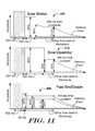
- FIG. 11 illustrates a set of detection profiles and parameters for an illustrative example
- FIG. 12 illustrates a full set of detection profiles and parameters for another illustrative example.
- Implantable devices typically calculate a heart rate or beat rate for the implantee.
- Heart or beat rate is typically given in beats-per-minute (bpm).
- Such devices then use the heart rate either alone or in conjunction with some other factor (sometimes morphology is used, for example) to determine whether the implantee needs therapy.
- the calculation of heart rate can be performed by observing the rate at which “events” are detected by the implanted device.
- an event is detected by comparing received signals to a detection threshold, which is defined by a detection profile. Illustrative examples of detection profiles are shown in FIGS. 3, 6A, 6B and 11-12 .
- a detected event is declared when the received signal crosses the detection threshold.
- a cardiac electrogram includes several portions (often referenced as “waves”) that, according to well known convention, are labeled with letters including P, Q, R, S, and T, each of which corresponds to particular physiological events. It is typical to design detection algorithms to sense the R-wave, though any portion, if repeatedly detected, can be used to generate a beat rate. If morphology (shape) analysis is used in addition to heart rate, the system may capture and/or analyze the portion of the cycle that includes the Q, R and S waves, referred to as the QRS complex. Other portions of the patient's cardiac cycle, such as the P-wave and T-wave, are often treated as artifacts that are not sought for the purpose of estimating heart rate, though this need not be the case.
- Sensing may be performed in the near field or far field. Intracardiac electrograms are dominated by signal components generated in the near field, while surface or subcutaneous sensing captures signals in the far field. The R-wave often has larger amplitude than other portions of the cardiac cycle, though this can vary depending upon how and from what location the signal is sensed and/or with patient physiology.
- each cardiac cycle is counted only once.
- Overdetection (such as a double or triple detection) may occur if the device declares more than one detected event within a single cardiac cycle. This may happen if an R-wave and a trailing T-wave are both detected from a single cardiac cycle or if a wide QRS complex is detected twice. Overdetection may also occur if noise causes an event to be declared when no cardiac event has taken place, for example, due to external noise, pacing artifact, skeletal muscle noise, electro-therapy, etc.
- Overdetection can lead to overcounting of cardiac cycles. For example, if one cardiac cycle takes place and a detection algorithm declares multiple detected events, overdetection has occurred. If the heart rate is then calculated by counting each of these detections, overcounting occurs.
- Calculated heart rates may be used alone or in combination with other factors to classify cardiac activity as malignant or benign. Therapy decisions are usually made based upon such classification. Overcounting in reliance on overdetected events can result in erroneously high rate calculation. Miscalculation of heart rate can lead to incorrect therapy decisions and, particularly, incorrect therapy delivery. However, simply preventing overdetection by rendering a device insensitive to received signals can cause undersensing, which may impair or delay delivery of needed therapy.
- An illustrative embodiment makes use of a detection method as shown in the high-level functional block diagram of FIG. 1 .
- the method is briefly introduced here, with more detailed examples provided below.
- the illustrative method makes use of a detection profile as shown in one of FIGS. 3, 6A, 6B, 11 and/or 12 .
- a relatively more sensitive detection profile is used, and when detected events are dissimilar from one another, a relatively less sensitive detection profile is used.
- a peak for a recent detected event is compared to a prior peak.
- the illustrative example uses the comparison at 10 to categorize the recent detected event peak as either similar 12 or dissimilar 14 relative to the prior peak.
- the comparison at 10 may take the following form, for example:
- a ⁇ New ⁇ ⁇ Peak ⁇ ⁇ Amplitude Prior ⁇ ⁇ Peak ⁇ ⁇ Amplitude ⁇ B where A and B are predetermined values. In the illustrative example, if the above formula yields a “True” outcome, then the peaks are similar; otherwise, they are dissimilar.
- the quotient in the middle of this formula is referred to as the peak ratio.
- A may be in the range of 0.5-0.9, and B may be in the range of 1.1-1.5. Additional examples of similar/dissimilar analysis are provided below.
- a “Similar” detection profile is applied, as shown at 16 .
- a “Dissimilar” detection profile is applied, as shown at 18 .
- the selection of the Similar or Dissimilar detection profile modifies the sensitivity of the detection method. In one example, the Similar Detection profile is more sensitive than the Dissimilar Detection profile as shown at 20 A/ 20 B. In another example, the Similar Detection profile is less sensitive than the Dissimilar Detection profile, as shown at 22 A/ 22 B.
- the adopted Similar or Dissimilar detection profile 16 , 18 is then used to detect the next detection profile threshold crossing, as shown at 24 .
- the method then iterates through A 26 .
- a detection profile typically defines amplitudes at given points in time, and if the captured signal exceeds the detection profile defined amplitude, a detection occurs. By raising or lowering the detection profile and/or modifying the timeline of the detection profile, sensitivity is raised or lowered.
- the similar/dissimilar analysis may include an interval rule.
- the likelihood of double detection decreases when the interval between two detections is long.
- two consecutive detections separated by a relatively long interval greater than, for example, 500 milliseconds are not subject to the similar/dissimilar analysis, as they are likely not overdetected during the long interval. Instead, when an interval of a length greater than a predetermined threshold is identified, one or the other of the similar or dissimilar detection profile is adopted automatically.
- FIG. 2 An illustrative subcutaneous cardiac stimulus system is shown in FIG. 2 .
- the subcutaneous system is shown relative to a heart 30 , and includes a canister 32 coupled to a lead 36 .
- the canister 32 houses operational circuitry for performing analysis of cardiac activity and for providing a stimulus output.
- a can electrode 34 is disposed on the canister 32 .
- a surface of the canister 32 may serve as an electrode.
- the lead 36 includes three illustrative electrodes shown as ring electrode 38 , coil electrode 42 , and tip electrode 40 . These electrodes 38 , 40 , 42 and the can electrode 34 may define a plurality of sensing vectors, such as V 1 , V 2 , V 3 and, optionally, V 4 . If desired, one or more vectors V 1 , V 2 , V 3 , and V 4 may be chosen for use as a default sensing vector, for example, as discussed in US Patent Application Publication Number 2007-0276445 titled SYSTEMS AND METHODS FOR SENSING VECTOR SELECTION IN AN IMPLANTABLE MEDICAL DEVICE. Illustrative subcutaneous systems are also shown in U.S. Pat. Nos.
- Stimulus may be applied using any chosen pair of electrodes; one illustrative example uses the can electrode 34 and the coil electrode 42 to deliver stimulus. In yet another embodiment, multiple sensing vectors may be used simultaneously.
- a programmer 44 is also shown.
- the programmer can be used to configure the implant system as desired through methods that are widely known. These may include, for example, radiofrequency or inductive telemetry communication.
- the present invention is not limited to any particular hardware, implant location or configuration. Instead, it is intended as an improvement upon any implantable cardiac monitoring and/or treatment system.
- Embodiments of the present invention may take the form of devices or systems for use as subcutaneous-only, transvenous single or multi-chamber, epicardial or intravascular implantable defibrillator or monitoring systems, or as methods of use in any such system.
- FIG. 2 omits various anatomical landmarks.
- the illustrative system shown would be implanted outside of the ribcage (not shown) of the implantee.
- the location illustratively shown places the canister 32 at approximately the left axilla of the implantee, level with the cardiac apex, with the lead 36 extending medially toward the sternum and then toward the head of the patient along the left side of the sternum.
- the implant may be similar to that shown in commonly assigned US Patent Application Publication Number 2006-0122676 titled APPARATUS AND METHOD FOR SUBCUTANEOUS ELECTRODE INSERTION, now U.S. Pat. No. 7,655,014.
- the canister 32 may be placed in anterior, lateral, and/or posterior positions including, without limitation, axillary, pectoral, and sub-pectoral positions, as well as placements on either the left or right side of the patient's torso.
- the lead 36 may then be placed in any of a number of suitable configurations including anterior-posterior combinations, anterior-only combinations, transvenous placement, or other vascular placements.
- An embodiment of a monitoring system may be a subcutaneously implanted system having a housing with multiple electrodes thereon, with or without a lead.
- FIGS. 3-5 provide an introduction to a detection profile and its use.
- the application of the detection profile of FIG. 3 to a captured cardiac signal is shown in FIG. 4 , which illustrates overdetection using such a profile.
- FIG. 5 illustrates calculation of “estimated peak” that is used to generate amplitudes defined by a detection profile as shown in FIGS. 3-4 .
- the detection profiles shown herein are illustrated using a rectified signal. Those of skill in the art will recognize that the detection profile for an unrectified signal would effectively define the detection profile on the negative side of the sensing baseline as well.
- FIG. 3 illustrates a detection profile at 50 , with portions thereof labeled for illustrative purposes.
- the detection profile includes a refractory period, shown in cross-hatching.
- the refractory period is an initial time period that follows a threshold crossing. During the refractory period, captured signal data may be recorded and/or analyzed, but additional detected events are not declared. Following the refractory period is an exponential decay period, as shown. The exponential decay brings the detection threshold down, over time, from a starting point to the sensing floor of the device.
- sensing floor may be defined by the hardware limits of the device and/or by the ambient noise environment of the device.
- a sensing floor may also be selected in any suitable manner. Values for the sensing floor may vary depending upon the characteristics of the particular implantable cardiac stimulus system including, for example, input circuitry, filter capability, electrode location and size, and patient physiology.
- the height shown for the detection profile during each refractory period represents the “estimated peak” amplitude of the cardiac signal at that time.
- the implanted device makes use of one or more prior detected events to estimate the amplitude of peaks in the cardiac signal. Illustrative calculations of estimated peak are shown in FIG. 5 .
- the exponential decay following the refractory period uses the estimated peak as its starting point, and follows an exponential decay curve from the estimated peak to the sensing floor or some other selected value.
- FIG. 4 illustrates a problem that may arise during application of the detection threshold of FIG. 3 , which is shown at 64 , to a captured cardiac signal 62 .
- refractory periods are indicated by cross-hatching, as shown at 60 , 66 , 68 , 70 and 72 .
- Refractory periods at 60 , 66 and 70 cover QRS complexes in the captured signal 62 ; these detections can be considered “accurate,” as the desired portion of the cardiac signal has been detected.
- T-waves are shown at 74 , 76 and 78 .
- the T-wave following refractory period 60 does not cause a detection, although it is close in amplitude to the decaying detection profile 64 .
- the next T-wave, at 76 crosses the decaying detection profile, resulting in a detection followed by refractory period 68 .
- the detection of the T-wave 76 creates two potential problems. First, an overdetection occurs, since two detections (resulting in refractory periods 66 , 68 ) occur in a single cardiac cycle. Second, the T-wave 76 has a different amplitude than the R-waves of the captured signal and can therefore affect the calculation of estimated peak, as shown by FIG. 5 .
- the illustrative example uses the average amplitude of two prior peaks as the “estimated peak.” As shown at 80 , correct identification of QRS complexes enables a calculation of estimated peak that is an average of the R-wave amplitude for the previous two QRS complexes. As shown at 82 , however, detection of the T-wave as the second peak causes a calculation of estimated peak that may be lower than the R-wave peak.
- the estimated peak shown at 68 is an average of the amplitudes for R-waves R 1 and R 2
- the estimated peak shown at 70 is an average of the amplitudes for R-wave R 2 and T-wave T 2 . Since the T-waves are lower in amplitude than the R-waves, as shown at 70 , the estimated peak following T-wave 76 is lowered, increasing the likelihood that another T-wave will also cause a threshold crossing and detection. In the illustrative example, T-wave 78 crosses the detection threshold, causing the system to again declare a detected event. Thus T-wave 76 contributes to the overdetection of T-wave 78 , and the overdetection of T-waves becomes a self-perpetuating condition.
- FIGS. 6A-6B show illustrative detection profiles that can be manipulated in accordance with some examples of the present invention.
- a detection profile is shown at 90 and includes a refractory segment having a refractory duration 92 , which is immediately followed by a first constant threshold segment (CT1) using a CT1% of the estimated peak for its amplitude and a CT1 duration 94 .
- CT1 a first constant threshold segment
- CT2 second constant threshold segment
- CT2 an exponential decay which begins at amplitude CT2% of the estimated peak and decays toward the sensing floor.
- At least the following variables may be manipulated to change the sensitivity of the detection profile:
- these variables are manipulated singly or in combination to increase or decrease sensitivity in response to identified similarity or dissimilarity between detected event peak amplitudes. For example, extending any of the durations 92 , 94 , 96 reduces the sensitivity of the overall detection profile. In some embodiments, the refractory period 92 remains fixed, while combinations of the other variables are modified.
- FIG. 6B illustrates another detection profile 100 .
- FIG. 6B incorporates a “dynamic floor.”
- the dynamic floor is a detection profile component that is set to a selected value above the sensing floor and used as an intermediate “floor” for the detection profile.
- An illustrative dynamic floor is invoked until a dynamic floor time-out (DFTO), at which time the detection profile begins decaying toward the sensing floor.
- DFTO dynamic floor time-out
- a detection profile 100 includes a refractory segment having a refractory duration 102 , which is followed by a first constant threshold segment (CT 1 ) using CT1% of the estimated peak as its amplitude and having a CT1 duration 104 .
- CT1 is a second constant threshold segment (CT2) using CT2% of the estimated peak as amplitude, and having a CT2 duration 106 .
- CT2 is a second constant threshold segment
- a first decay period which starts from the amplitude of CT2% and ends at a dynamic floor having an amplitude DF %, with each of CT2% and DF % based on the estimated peak.
- the DFTO 108 is used to define the duration of the first decay.
- a second decay to the sensing floor is used to the duration of the first decay.
- the first and second decays may use the same time constant of decay, or may use different time constants of decay.
- CT2 may be omitted such that the first decay starts from CT1%, or some other predetermined percentage of estimated peak, or even from a constant not associated with the estimated peak.
- CT2 is used as a placeholder for the start of the first decay period and is given a very short duration equal to a single sample period.
- exponential decays are shown in FIGS. 6A-6B , any suitable decay shape may be used, for example, including constant ramp decays or other non-exponential functions, for example.
- FIGS. 7A-7B show illustrative adaptive profiles and a system-level response to changes in peak amplitudes.
- a first detection is shown at 120 .
- the detection profile is shown in a form generally corresponding to that of FIG. 6B , though a detection profile as in FIG. 6A could also be used. Additional detections occur at 122 , 124 and 126 .
- the illustrative system keeps track of the peak amplitude during the refractory periods (again shown as cross-hatched blocks).
- the peak values are shown beneath the refractory periods in analog-to-digital conversion (ADC) units.
- ADC units represent the output of analog-to-digital conversion within the device; in the Figures these units are shown merely to help illustrate other concepts.
- the peak values are used to calculate peak ratios shown at 128 .
- the peak ratio for detections 120 and 122 is 0.92.
- peak ratios of about 0.8-1.2 are defined as indicating “similar” peaks, so detections 120 and 122 are considered similar.
- Other ranges defining similar/dissimilar peak ratios, and other measures of similar/dissimilar may be used.
- the detection profile following detection 122 is similar to the detection profile following detection 120 because the prior peak amplitude for detection 120 is similar to that of the immediately preceding peak amplitude (the preceding peak is not shown).
- T-wave 132 following detection 122 causes an overdetection 124 .
- the peak for T-wave 132 is lower than the R-wave peak for detection 122 .
- the system as shown has a built-in delay of one event, so detection following the overdetection 124 uses the “similar” detection profile. However, in contrast to events 120 , 122 and 124 , the detected event at 126 is followed by a detection profile based on “dissimilar” detection profile parameters. This results in modifications, as indicated, including extended CT1 duration and a higher CT1%. As a result, the T-wave shown at 134 does not cause a detection threshold crossing and no detected event is declared for T-wave 134 . The modification in view of the dissimilar peak amplitudes prevents continued overdetection in the illustrative example shown in FIG. 7A .
- FIG. 7A makes use of the following detection profile parameters (% indicates percent of the estimated peak):
- the inclusion of DF % and DF TO is not apparent from FIG. 7A and, if desired, these may be omitted in some embodiments.
- the time constants for decay may be any suitable value. In an illustrative example, the time constant of decay for the above parameters is in the range of 400 milliseconds. Additional variations of and ranges for these parameters are provided below.
- FIG. 7B shows the analysis as it continues, with more detected events shown.
- detected event 150 is associated with a detection profile using a “similar” detection profile configuration. This results in overdetection of the trailing T-wave, shown at detection 152 .
- detection 152 of a T-wave results in reduction of the estimated peak (again, the estimated peak is shown as the height of the cross-hatched block that represents the refractory period).
- a low peak ratio causes the use of a “dissimilar” detection profile configuration following the detection at 154 .
- the delay in this illustrative example is based on a hardware environment in which the peak associated with a given refractory period is not read as a peak until after the end of the given refractory period. It is contemplated that in some hardware environments, the peak and peak ratio could be found in real-time, such that a one beat delay is avoided. In such an example, a “dissimilar” configuration could be invoked during or following the refractory period of detection 152 .
- the detection profile successfully passes over the next T-wave 160 .
- the next detection shown at 156 , is again an accurate detection caused by an R-wave.
- the peak ratio of 1.57 causes the continued use of the “dissimilar” configuration following detection 156 .
- the detection profile successfully passes over a T-wave.
- Detection 158 follows. As indicated by the line/arrow 166 , the similarity of the peaks for detections 154 and 156 (peak ratio of 1.01) causes the resumption of the more sensitive “similar” configuration.
- the T-wave following detection 158 is detected.
- the “dissimilar” detection profile configuration will be invoked again. As shown in this illustrative example, during time periods in which overdetection is avoided, similar peaks occur and the more sensitive detection profile configuration associated with similar peaks is invoked. Thus a cycle can develop in which the device transitions between dissimilar and similar detection profile configurations.
- the illustrative detection pattern results in sets of four detections in which three R-waves and one overdetected T-wave appear. If the actual heart rate is 100 bpm, consistent overdetection of every T-wave (for example, as shown in FIG. 4 ) would yield a calculated rate of 200 bpm. A beat rate of 200 bpm may be considered tachyarrhythmic for a substantial number of patients who are candidates for ICD implantation and may create a risk of inappropriate therapy. The example of FIG. 7B , however, would calculate a rate of about 133 bpm, which is unlikely to cause inappropriate therapy.
- a counter or other hysteresis tool may be used to slow the cycling between “similar” and “dissimilar” detection profile configurations.
- a detection profile configuration would be used for some predetermined number of detections before invoking a different detection profile configuration. For example, at least 5 detections would occur using a detection profile configuration before a different one could be called.
- the hysteresis could be “one-sided,” that is, hysteresis could apply only when one of the “similar” or “dissimilar” configurations is invoked. In the example of FIG. 7B , no added hysteresis is provided to avoid delayed identification of malignant fast arrhythmias such as ventricular fibrillation.
- FIG. 8 is a flow diagram of an illustrative example of cardiac signal analysis in an implantable medical device.
- the illustrative example of FIG. 8 includes a detection loop shown at 200 , in which incoming signal is filtered, amplified and sampled, as shown at 202 .
- the signal may be rectified in block 202 , if desired.
- the samples are then compared to a threshold defined by a detection profile as indicated at step 204 . Once a threshold crossing occurs, the detection loop 200 is exited and a detected event is declared as shown at 206 . If morphology analysis is used, when the detected event is declared 206 , various steps may be taken to define a sample window associated with the detected event, for example, as discussed in commonly assigned US Patent Application Publication Number 2006-0116595, now U.S. Pat. No. 7,376,458 and titled METHOD FOR DEFINING SIGNAL TEMPLATES IN IMPLANTABLE CARDIAC DEVICES; and/or commonly assigned US Patent Application Publication Number 2006-0116725, now U.S. Pat. No. 7,477,935 and titled METHOD AND APPARATUS FOR BEAT ALIGNMENT AND COMPARISON.
- preliminary analysis is performed, as indicated at 208 .
- This may include, for example, waveform appraisal discussed in commonly assigned U.S. Pat. No. 7,248,921, titled METHOD AND DEVICES FOR PERFORMING CARDIAC WAVEFORM APPRAISAL. If the preliminary analysis 208 reveals that the detected event 206 does not appear to be a cardiac event (or a cardiac event masked/covered by substantial noise), the detected event 206 is identified as a suspect event, and data associated with the detected event 206 is discarded, with the method then reverting back to the detection loop 200 using the same detection parameters that were previously in use. In some embodiments, step 208 may be omitted.
- rhythm analysis is performed, as indicated at 210 .
- Rhythm analysis may include any of a number of steps/methods.
- One illustrative example uses calculated heart rates and/or morphology analysis to create detected event markers that indicate whether a given detected event is “shockable” or “nonshockable”.
- Morphology analysis may include, for example, comparison to a stored or dynamically changing template (for example, using correlation waveform analysis), QRS width analysis, and/or other shape-based analysis.
- a buffer of shockable/nonshockable markers may be maintained as an X/Y counter. If a predetermined X/Y ratio is met, then the X/Y counter indicates therapy. For example, an 18/24 threshold may be used, where, if 18 of the previous 24 detected events that pass preliminary analysis are “shockable,” the X/Y counter indicates therapy.
- the phrase “indicates therapy” is intended to mean that the implanted device has identified a treatable condition and therefore indicates that therapy is likely needed by the patient.
- one or more persistence factors may be considered. Persistence may be observed by determining whether the X/Y counter indicates therapy for a threshold number of consecutive detected events. Illustrative examples of persistence analysis are set forth in commonly assigned US Patent Application Publication Number 2006-0167503, now U.S. Pat. No. 8,160,697, titled METHOD FOR ADAPTING CHARGE INITIATION FOR AN IMPLANTABLE CARDIOVERTER-DEFIBRILLATOR.
- the method also performs steps to prepare for return to the detection loop 200 . These steps may include determination of whether similar or dissimilar detected event peaks are observed, as shown at 212 .
- the outcome of analysis at step 212 determines the detection profile configuration used to set the detection profile in step 214 .
- the detection profile, as configured in step 214 is then used upon return to the detection loop 200 .
- step 214 may reduce the likelihood of persistent overdetection. This may, in turn, increase the accuracy of rhythm classification. As indicated by FIG. 7B , overdetection may occur even with step 214 , however, because the modifications can reduce the frequency with which overdetections occur, the method helps avoid incorrect therapy decisions.
- FIG. 9 is a flow diagram of another illustrative example of cardiac signal analysis in an implantable medical device.
- a detection loop 250 is shown again including steps of filtering, amplifying and sampling 252 and comparing the captured signal to a threshold 254 .
- a threshold crossing causes an exit from the detection loop 250 , and a detected event is declared as shown at 256 .
- Preliminary analysis 258 is again performed, as before, with noisy or suspect event identification causing a return to the detection loop 250 .
- the method continues by calculating a heart rate, as indicated at 260 .
- double detection analysis may be performed prior to calculating heart rate, as noted at 262 .
- Block 262 may be omitted, if desired.
- Double detection analysis 262 , 264 may include any suitable method for identifying double detections. Some examples can be found in U.S. Provisional Patent Application No. 61/051,332, titled METHODS AND DEVICES FOR IDENTIFYING AND CORRECTING OVERDETECTION OF CARDIAC EVENTS. The following are examples of analyses that may occur in blocks 262 or 264 :
- rhythm analysis is performed as indicated at 266 .
- the detection profile is set, as shown at 268 , using yet another detection profile configuration, this one being used when the calculated rate (step 260 ) is relatively high ( FIGS. 11-12 show examples).
- the method then iterates at A 270 .
- the analysis determines whether detected event peaks are similar or dissimilar, as shown at 272 .
- the method sets the detection profile using similarity/dissimilarity information, as shown at 274 .
- the method next returns to the detection loop 250 via block A 270 .
- the “relatively low” and “relatively high” rates are calculated on the basis of an average of intervals between detected events that pass preliminary analysis 258 and, if included, the first pass of double detection analysis at 262 .
- the calculated rate is Low when a heart rate of less than about 148 bpm is calculated from an average of four intervals between detected events. Further in the illustrative example, the calculated rate is High when a heart rate greater than about 167 bpm is calculated. In the example, these values may lie on either side of a hysteresis band in which the characterization of “High” and “Low” rates depends upon the characterization of rate for the previous detected event. Thus, in the illustrative example, if the newly calculated rate is 155 bpm, and the previous rate was characterized as “High,” then the rate is again characterized as “High”. Other definitions of “High” and “Low” may be used and/or these values may be programmed during a telemetry session.
- FIG. 10 provides an example showing how invocation of a “dissimilar” detection profile can slow the identification of a ventricular fibrillation.
- FIG. 11 provides illustrative examples of sets of parameters that may be used in the embodiment of FIG. 9 to define detection profiles. The addition of the fast detection profile parameters may avoid a delay in identification of a malignant rhythm shown in FIG. 10 .
- FIG. 12 provides an even more detailed example.
- the illustrative method of FIG. 9 uses computationally expensive “enhanced analysis” (at blocks 264 and 266 ) when calculated rates are relatively high, and simpler computations when calculated rates are relatively low.
- “enhanced analysis” at blocks 264 and 266 ) when calculated rates are relatively high, and simpler computations when calculated rates are relatively low.
- One example has been discussed above relative to FIG. 7B : a cardiac rhythm having an intrinsic rate of 100 cardiac cycles per minute included relatively large T-waves that caused overdetection.
- the cyclic invocation of the “dissimilar” detection profile configuration passes over the majority of the T-waves, resulting in a calculation of 133 bpm, rather than 200 bpm that would occur if each T-wave was counted.
- the peak ratio calculation allows use of detection profile modifications to reduce reliance on more computationally costly tools, potentially reducing power consumption.
- FIG. 10 illustrates detection using an illustrative example of detection profiles during onset of ventricular fibrillation.
- a detection is shown at 300 with an R-wave peak occurring during the refractory period, and the detection profile easily passes over the following T-wave.
- the detection profile following detection 300 is defined using “similar” peak parameters.
- the cardiac rhythm devolves into a ventricular fibrillation (VF), characterized by fast-moving, low amplitude peaks.
- VF ventricular fibrillation
- the first detection of a VF peak occurs at 304 .
- the amplitude for detection 304 is reduced significantly relative to peak 300 .
- the system continues to use the same “similar” peak parameters based upon comparison of the detection at 300 to a prior peak.
- Another peak is detected at 306 , with underdetection or “dropout” occurring for several VF Peaks.
- “dissimilar” parameters are used following detection 306 . Due to averaging of the two prior detections, the estimated peak for detection 306 is still quite a bit higher than the current peak.
- a VF peak is captured at 308 , and is followed at 312 with another detected VF peak.
- the estimated peak measurement allows the detection profile to chase down the VF signal by lowering the amplitude of the highest portions of the detection profile as lower amplitude signals are captured.
- VF is often inconsistent in amplitude and the baseline may wander.
- the use of the “dissimilar” profile may create additional problems with detection due to the intrinsic variability of VF.
- the peak for detection 312 is higher than the peak for detection 308 .
- the variability yields peak ratios indicating that the peaks are “dissimilar.”
- the dissimilar profile is then invoked as shown at 316 . Because the dissimilar profile in this illustrative example is relatively less sensitive than the similar profile, this can delay further detections, as shown.
- One or more cardiac cycles can then go undetected by the implanted device. More underdetection may follow, since, as shown at 314 , peak 312 is dissimilar from the following peak.
- the upper portion of the Figure indicates detection intervals, at 320 .
- a relatively long interval is created by the dissimilar detection profile configuration. If an average of several intervals is used to estimate the heart rate of the implantee, a long interval caused by underdetection may throw several calculations into question. For at least this reason, the method of FIG. 9 may incorporate a fast tachy detection profile 1070 shown in FIG. 12 .
- FIG. 11 illustrates a set of detection profile configurations for an illustrative example.
- the detection profiles include a slow profile having similar and dissimilar variants 400 , 410 , and a fast profile 420 with similar and dissimilar variants.
- the variants on the fast profile 420 are shown together to simplify the illustration.
- the profiles are drawn to scale to show the differences in duration and in relative scaling of amplitudes. Refractory periods are shown with cross-hatching and have heights that correspond to an estimated peak.
- slow means less than about 147 bpm
- fast means greater than about 167 bpm
- a hysteresis band is used in between, in fashion similar to that explained above with reference to FIG. 9 .
- the hysteresis band may be larger, smaller, or omitted.
- the upper bound of “slow” may be anywhere in the range of 100-200 bpm
- the lower bound of “fast” may be in the range of, for example, 120-240 bpm, for example. These values may be modified further, if desired.
- the illustrative slow similar profile 400 is for use when the calculated heart rate for the implantee is relatively slow and the peak amplitudes of a selected pair of detected events are similar to one another.
- the illustrative example uses a 200 millisecond refractory period, followed by a 200 millisecond first constant-threshold period at an amplitude of 80% of the estimated peak, followed by a 4 millisecond second constant threshold period at an amplitude of 50% of the estimated peak, followed by a first time-decaying portion starting at an amplitude of 50% of the estimated peak and decaying to 37.5% of the estimated peak using a time constant of 400 milliseconds.
- the first time-decaying portion of the illustrative slow similar profile 400 ends 720 milliseconds from the start of the refractory period and is followed by a second time-decaying portion that starts with an amplitude of 37.5% of the estimated peak and decays to the detection floor using a 400 millisecond time constant.
- the illustrative slow dissimilar profile 410 is for use when the calculated rate for the implantee is relatively slow and the peak amplitudes of a selected pair of detected events are dissimilar from one another.
- the illustrative example uses a 200 millisecond refractory period, followed by a 350 millisecond first constant threshold period at an amplitude of 95% of the estimated peak, followed by a second constant threshold period having a duration of 4 milliseconds at an amplitude of 50% of the estimated peak.
- the first “decay” period is actually used as a continuation of the second constant threshold period, as there is no decay since the threshold remains at an amplitude of 50% of the estimated peak until expiration of the first decay period, which occurs 720 milliseconds after the beginning of the refractory period.
- a second time-decaying portion follows, beginning at an amplitude of 50% of the estimated peak and decaying to the detection floor using a 400 millisecond time constant.
- the illustrative fast profile 420 is for use when the calculated rate in the implantee is relatively fast. For efficient illustration, both the similar and dissimilar profiles are shown at 420 .
- the fast profile 420 in the illustrative example, includes a 156 millisecond refractory period followed by a first constant threshold portion having duration of 80 milliseconds and an amplitude of 60% of the estimated peak.
- the first constant threshold period is followed by a second constant threshold period having duration of 4 milliseconds with amplitude that varies in response to similarity/dissimilarity.
- a dynamic floor is also defined at the same amplitude as the second constant threshold period, such that the first “decay” time period actually does not decay.
- the fast profile 420 uses 37.5% of the estimated peak for the second constant threshold period and the dynamic floor.
- the fast profile 420 uses 50% of the estimated peak for the second constant threshold period and the dynamic floor.
- the method selects between a first pair of detection profiles when rates are relatively low, using peak similarity/dissimilarity to determine which profile to use. Further in the illustrative example, the method selects between a second pair of profiles when rates are relatively high, again using peak similarity/dissimilarity to determine which profile to use.
- the fast profiles 420 are more sensitive than the slow profiles, and the similar profiles are more sensitive than the dissimilar profiles.
- the greater sensitivity of the fast profiles 420 may help to track a malignant fast arrhythmia to relatively low amplitudes. This allows the detection profile to match the often low amplitude of malignant fast arrhythmia such as VF relatively quickly.
- an overdetection identification method uses pattern identification to determine that overdetection is occurring, detection profile manipulation that prevents some, but not all, overdetection may impede the pattern identification. Increasing sensitivity at high rates may avoid interference between the two system tools.
- FIG. 12 illustrates a full set of detection profile configurations for another, detailed illustrative example.
- the level of detail in the example is not intended to limit the invention to any particular set of profiles and/or level of complexity.
- the illustrative example of FIG. 12 integrates several concepts including the use of multiple profiles, definition of fast and slow profiles, and the use of a tachyarrhythmia condition. Before explaining each profile, the sensing parameters including each of Tachy On/Off, and fast/slow are defined.
- a tachycardia zone is defined for an implantable device as a programmable parameter.
- a physician or other user of the programmer 44 can set the lowest rate for which a tachycardia will be declared. Rates are shown graphically at 1000 , with VT Zone PP representing the tachycardia zone programmable parameter.
- VT Zone PP can be set in a range of 170 bpm to 240 bpm. Any time the calculated rate for the illustrative example exceeds the VT Zone PP, a tachycardia condition is invoked.
- the device enters a “Tachy On” condition.
- the “Tachy On” condition remains in effect until the condition terminates.
- the Tachy On condition is terminated once a predetermined number of consecutive events are captured at a rate below the VT Zone PP rate.
- 24 consecutive rate calculations below VT Zone PP will terminate the Tachy On condition.
- An offset to the VT Zone PP may also be used to prevent toggling of Tachy On/Off, in addition to or as a substitute for the 24 consecutive calculations below VT Zone PP. Any time the “Tachy On” condition is not in effect, the device is in a “Tachy Off” condition.
- Rates below a low threshold are considered slow, and rates above a high threshold are considered fast in the illustrative embodiment. Rates between the thresholds fall within a hysteresis zone. When in the hysteresis zone, the rate is considered fast if the previous rate calculation was also considered fast, and slow if the previous rates calculation was considered slow.
- VT Zone PP is programmable to values that are above the high threshold. Therefore, some rates will be considered “Fast” but will not meet the criteria to create a “Tachy On” condition.
- Illustrative values for the high and low thresholds are shown as 148 and 167 bpm; the invention is not limited to these values.
- the 24 consecutive calculation rule used to determine the end of a Tachy On condition means that it is also possible to have a Slow rate while the “Tachy On” condition is still invoked.
- a special case is encompassed by the illustrative example.
- data seeding occurs following delivery of a stimulus shock. This is disclosed in U.S. patent application Ser. No. 12/355,552, published as US Patent Application Publication Number 2009-0187227, titled DATA MANIPULATION FOLLOWING DELIVERY OF A CARDIAC STIMULUS IN AN IMPLANTABLE CARDIAC STIMULUS DEVICE.
- the dynamic floor may be enabled, without changing the Tachy On condition.
- the illustrative example enables the dynamic floor until a beat rate above VT Zone PP is calculated.
- post-shock sensing includes a special state in of Tachy On, Dynamic Floor On, referred to as the Post-Shock Tachy On condition.
- profiles 1050 , 1060 and 1070 do not show a dynamic floor. Instead, the first decay period is shown as decaying to the noise floor or sensing floor of the system.
- the system allows for a large number of different variables to be manipulated.
- the following table provides numeric information for the illustrative example, with amplitudes provided as a percentage of estimated peak, and durations provided in milliseconds:
- FIG. 12 is intended to be an illustrative example, and the particular configurations, features and numeric examples shown are not intended to limit the present invention.
- any suitable shape may be used. In some examples, this may include exponential decay, any other asymptotic decay, or straight-line decay. Also, while the above embodiments refer to constant threshold periods, substituting a decay period is encompassed in additional embodiments. Ramping of the profile by increasing the threshold during a time period is another alternative that may replace decay or constant threshold periods.
- implantable devices typically use heart rate either alone or in conjunction with some other factor to determine whether the implantee needs therapy.
- “Some other factor” may include any suitable factor such as, for example, the morphology/shape of cardiac signals associated with detected events, and/or observation of any non-cardiac and/or non-electrical signal.
- An example of morphology analysis includes correlation analysis relative to a stored template representing a predetermined cardiac condition, such as a normal sinus rhythm or some predetermined arrhythmic condition such as atrial fibrillation. Difference of area and difference of squares are two forms of correlation analysis that may be performed. Other analysis, such as principle components analysis, source separation, wavelet transform and other mathematical analytics could also be performed as part of morphology analysis.
- Non-cardiac or non-electrical signals may include, for example, pulse oximetry data, patient respiration data, accelerometer data indicating patient movement, optical interrogation of blood composition, or any other suitable factor including measured temperature or blood pressure within an implantee. Some of these factors may be calculated using tissue impedance measurements.
- Non-cardiac signals may be used in several forms including, for example, to ensure that a captured electric signal is in fact a cardiac signal, or to inform decision making by providing an indication of patient status (for example, Is the patient's breathing accelerated, labored, normal, or stopped?, or Is the patient upright or laying down?).
- the present invention contemplates embodiments in which these additional factors, or any other suitable factor, are included in making stimulus delivery decisions.
- the formula provided above for determining whether “similar” or “dissimilar” events are occurring is an illustrative example.
- the approach shown compares the two most recent peaks to determine whether they are similar. Other factors may be used. For example, a system may maintain statistics regarding prior peak activity or trend activity and may use the average or trend average and a standard deviation or variance to determine whether a newly detected event likely falls within “similar” or “dissimilar” bounds.
- similar/dissimilar may be determined relative to the estimated peak, rather than the most recent peak.
- peak-to-peak ratios are calculated and recorded to generate statistics for peak ratios. An unexpected peak ratio outcome falling outside of statistical bounds may be considered as indicating dissimilarity.
- Hysteresis may be built into the similar/dissimilar identification step.
- a three part range for the peak ratio may be used as follows:
- Peak similarity is one method of determining whether consecutive detected events are similar or dissimilar.
- Another method may include morphological analysis. For example, two consecutive events may be analyzed by correlation waveform analysis to determine whether the two events are similar or dissimilar.
- a series of detected events may each be compared to a template to determine whether similarity or dissimilarity relative to the template occurs.
- events may be compared in a string of comparisons, for example, Event(n) may be compared to each of Event(n ⁇ 1) and Event(n ⁇ 2) to observe whether similar/dissimilar patterns emerge, likely indicating overcounting and, in the illustrative example, justifying the use of a less sensitive detection profile.
- the comparison of a detected event to a previous detected event is also accurate to describe the comparison of a detected event to a previous detected event, either in simple amplitude or in morphology, as comparison of the detected event to stored data to determine the similarity of a most recent detected event to the stored data.
- the stored data may come from analysis of one or more prior events. This provides a more generic description of the underlying activity.
- Est Peak[ n ] Peak[ n ⁇ 1]
- Est Peak[ n ] (Peak[ n ⁇ 1]+Peak[ n ⁇ 2])/2
- Est Peak[ n ] (Peak[ n ⁇ 1]+Est Peak[ n ⁇ 1])/2
- [n] represents the event under consideration
- [n ⁇ 1, n ⁇ 2] represent prior detected events.
- Other, more complex functions may be used.
- the similarity/dissimilarity of a newly detected peak to the prior peak or estimated peak may be analyzed to determine whether to exclude the new detected peak from an updated calculation of estimated peak.
- the period between consecutive detections may also control which detection profile is invoked. In on example, if the period between two detections exceeds a threshold of, for example, 500-1000 ms, it is assumed that the detections do not originate in a single cardiac cycle, and a “Similar” detection profile is invoked.
- Example B the CT2 component is excluded from the detection profile when dissimilar events are identified. Some embodiments incorporate this variation.
- the Dissimilar Profile is more sensitive here than the Similar profile, by virtue of a shorter refractory period and omission of the CT2 parameters. As noted above, this may encourage consistent overdetection that can be identified and corrected by other methods.
- Threshold Amplitude P % of Est Peak+Constant
- a maximum value for CT1% and CT2% may be set to the maximum dynamic range of the ADC output, or to some other predetermined maximum.
- Some embodiments will be method embodiments incorporating one or more of the above features/sub-methods in various combinations. Some embodiments will be devices adapted to perform the methods discussed above. Some embodiments will take the form of tangible media, such as magnetic, electric, or optical storage media, incorporating controller readable instruction sets. Some embodiments will take the form of or comprise controllers/microcontrollers associated with stored instruction sets for directing operations of various components in a device in accordance with one or more methods.
- an illustrative example may make use of a microcontroller-driven system which includes an input switch matrix for selecting one or more signal vectors as a sensing vector.
- the switch matrix leads to one or more amplifiers and filtering circuits that in turn couple to analog-to-digital conversion circuitry. Additional filtering of the incoming signal may be performed in the digital domain including, for example, 50/60 Hz notch filters.
- the incoming signal may then be analyzed using the microcontroller and any associated suitable registers and logic circuits.
- Some embodiments include, for example, dedicated hardware for peak or event detection and measurement, or for correlation waveform analysis.
- a sub-circuit for charging high-voltage or stimulus capacitors may have any suitable form.
- One example uses a charger taking the form of a flyback transformer circuit, a structure well known in the art. Any process and/or circuit that enables relatively low voltage batteries to charge capacitors to relatively high voltages may be used.
- the device may further include output circuitry comprising, for example, an output H-bridge or modification thereof for controlling output polarity and duration from the high-power capacitor.
- Control circuitry associated with the H-bridge may be included, for example, to monitor or control current levels for constant current output signals or for performing diagnostic functions.
- the circuitry may be housed in a hermetically sealed canister.
Abstract
Methods, systems, and devices for signal analysis in an implanted cardiac monitoring and treatment device such as an implantable cardioverter defibrillator. In some illustrative examples, detected events are analyzed to identify changes in detected event amplitudes. When detected event amplitudes are dissimilar from one another, a first set of detection parameters may be invoked, and, when detected event amplitudes are similar to one another, a second set of detection parameters may be invoked. Additional methods determine whether the calculated heart rate is “high” or “low,” and then may select a third set of detection parameters for use when the calculated heart rate is high.
Description
The present application is a divisional of U.S. patent application Ser. No. 12/399,901, filed Mar. 6, 2009, now U.S. Pat. No. 8,565,878, which claims the benefit of and priority to U.S. Provisional Patent Application Ser. No. 61/034,938, filed Mar. 7, 2008 and titled ACCURATE CARDIAC EVENT DETECTION IN AN IMPLANTABLE CARDIAC STIMULUS DEVICE, the disclosure of which is incorporated herein by reference.
The present application is related to U.S. patent application Ser. No. 12/399,914, filed Mar. 6, 2009 and titled METHODS AND DEVICES FOR IDENTIFYING AND CORRECTING OVERDETECTION OF CARDIAC EVENTS, published as US Patent Application Publication Number 2009-0259271, now U.S. Pat. No. 8,160,686, which claims the benefit of and priority to U.S. Provisional Patent Application No. 61/051,332, filed May 7, 2008, and the disclosures of which is also incorporated herein by reference.
The present invention relates generally to implantable medical device systems that sense and analyze cardiac signals. More particularly, the present invention relates to implantable medical devices that capture cardiac signals within a patient's body in order to classify cardiac activity and direct therapy for treatment of arrhythmias.
Implantable cardiac stimulus devices typically sense cardiac electrical signals within a patient in order to classify the patient's cardiac rhythm as normal/benign or malignant in order to prevent, treat, or terminate malignant rhythms. Such malignant rhythms can include, for example, ventricular fibrillation and some ventricular tachycardias. How accurately an implantable medical device analyzes captured signals determines how appropriately it can direct therapy.
New and alternative methods and devices for detection and/or analysis of captured cardiac events in implantable medical devices are needed.
Various illustrative embodiments of the present invention are directed toward improving accuracy of cardiac event detection by implantable medical devices. The invention may be embodied in methods and/or devices.
The following detailed description should be read with reference to the drawings. The drawings, which are not necessarily to scale, depict illustrative embodiments and are not intended to limit the scope of the invention.
Unless implicitly required or explicitly stated, the methods below do not require any particular order of steps. It should be understood that when the following examples refer to a “current event,” in some embodiments, this means that the most recently detected event is being analyzed. However, this need not be the case, and some embodiments perform analysis that is delayed by one or more event detections or a fixed period of time.
Implantable devices typically calculate a heart rate or beat rate for the implantee. Heart or beat rate is typically given in beats-per-minute (bpm). Such devices then use the heart rate either alone or in conjunction with some other factor (sometimes morphology is used, for example) to determine whether the implantee needs therapy.
The calculation of heart rate can be performed by observing the rate at which “events” are detected by the implanted device. In an illustrative example, an event is detected by comparing received signals to a detection threshold, which is defined by a detection profile. Illustrative examples of detection profiles are shown in FIGS. 3, 6A, 6B and 11-12 . A detected event is declared when the received signal crosses the detection threshold.
A cardiac electrogram includes several portions (often referenced as “waves”) that, according to well known convention, are labeled with letters including P, Q, R, S, and T, each of which corresponds to particular physiological events. It is typical to design detection algorithms to sense the R-wave, though any portion, if repeatedly detected, can be used to generate a beat rate. If morphology (shape) analysis is used in addition to heart rate, the system may capture and/or analyze the portion of the cycle that includes the Q, R and S waves, referred to as the QRS complex. Other portions of the patient's cardiac cycle, such as the P-wave and T-wave, are often treated as artifacts that are not sought for the purpose of estimating heart rate, though this need not be the case.
Sensing may be performed in the near field or far field. Intracardiac electrograms are dominated by signal components generated in the near field, while surface or subcutaneous sensing captures signals in the far field. The R-wave often has larger amplitude than other portions of the cardiac cycle, though this can vary depending upon how and from what location the signal is sensed and/or with patient physiology.
Typically, for purposes of ascertaining rate each cardiac cycle is counted only once. Overdetection (such as a double or triple detection) may occur if the device declares more than one detected event within a single cardiac cycle. This may happen if an R-wave and a trailing T-wave are both detected from a single cardiac cycle or if a wide QRS complex is detected twice. Overdetection may also occur if noise causes an event to be declared when no cardiac event has taken place, for example, due to external noise, pacing artifact, skeletal muscle noise, electro-therapy, etc.
Overdetection can lead to overcounting of cardiac cycles. For example, if one cardiac cycle takes place and a detection algorithm declares multiple detected events, overdetection has occurred. If the heart rate is then calculated by counting each of these detections, overcounting occurs.
Calculated heart rates may be used alone or in combination with other factors to classify cardiac activity as malignant or benign. Therapy decisions are usually made based upon such classification. Overcounting in reliance on overdetected events can result in erroneously high rate calculation. Miscalculation of heart rate can lead to incorrect therapy decisions and, particularly, incorrect therapy delivery. However, simply preventing overdetection by rendering a device insensitive to received signals can cause undersensing, which may impair or delay delivery of needed therapy.
An illustrative embodiment makes use of a detection method as shown in the high-level functional block diagram of FIG. 1 . The method is briefly introduced here, with more detailed examples provided below. The illustrative method makes use of a detection profile as shown in one of FIGS. 3, 6A, 6B, 11 and/or 12 . In the illustrative example of FIG. 1 , when detected events are similar to one another, a relatively more sensitive detection profile is used, and when detected events are dissimilar from one another, a relatively less sensitive detection profile is used.
As shown at step 10, a peak for a recent detected event is compared to a prior peak. The illustrative example uses the comparison at 10 to categorize the recent detected event peak as either similar 12 or dissimilar 14 relative to the prior peak. The comparison at 10 may take the following form, for example:
where A and B are predetermined values. In the illustrative example, if the above formula yields a “True” outcome, then the peaks are similar; otherwise, they are dissimilar.
The quotient in the middle of this formula is referred to as the peak ratio. In an illustrative example, A=0.8 and B=1.2. In other examples, A may be in the range of 0.5-0.9, and B may be in the range of 1.1-1.5. Additional examples of similar/dissimilar analysis are provided below.
If the recent detected event peak is similar to the prior peak, as shown at 12, a “Similar” detection profile is applied, as shown at 16. On the other hand, if the recent detected event peak is dissimilar from the prior peak, as shown at 14, a “Dissimilar” detection profile is applied, as shown at 18. The selection of the Similar or Dissimilar detection profile modifies the sensitivity of the detection method. In one example, the Similar Detection profile is more sensitive than the Dissimilar Detection profile as shown at 20A/20B. In another example, the Similar Detection profile is less sensitive than the Dissimilar Detection profile, as shown at 22A/22B.
The adopted Similar or Dissimilar detection profile 16, 18 is then used to detect the next detection profile threshold crossing, as shown at 24. The method then iterates through A 26.
Examples where a detection profile is more or less sensitive are shown below. In short, a detection profile typically defines amplitudes at given points in time, and if the captured signal exceeds the detection profile defined amplitude, a detection occurs. By raising or lowering the detection profile and/or modifying the timeline of the detection profile, sensitivity is raised or lowered.
In another embodiment, the similar/dissimilar analysis may include an interval rule. For example, the likelihood of double detection decreases when the interval between two detections is long. In an illustrative embodiment, two consecutive detections separated by a relatively long interval (greater than, for example, 500 milliseconds) are not subject to the similar/dissimilar analysis, as they are likely not overdetected during the long interval. Instead, when an interval of a length greater than a predetermined threshold is identified, one or the other of the similar or dissimilar detection profile is adopted automatically.
It is contemplated that the present invention may be embodied in several forms including at least implantable cardiac monitoring systems and implantable cardiac stimulus systems. An illustrative subcutaneous cardiac stimulus system is shown in FIG. 2 . The subcutaneous system is shown relative to a heart 30, and includes a canister 32 coupled to a lead 36. The canister 32 houses operational circuitry for performing analysis of cardiac activity and for providing a stimulus output. A can electrode 34 is disposed on the canister 32. In some embodiments, rather than a discrete electrode 34, a surface of the canister 32 may serve as an electrode.
The lead 36 includes three illustrative electrodes shown as ring electrode 38, coil electrode 42, and tip electrode 40. These electrodes 38, 40, 42 and the can electrode 34 may define a plurality of sensing vectors, such as V1, V2, V3 and, optionally, V4. If desired, one or more vectors V1, V2, V3, and V4 may be chosen for use as a default sensing vector, for example, as discussed in US Patent Application Publication Number 2007-0276445 titled SYSTEMS AND METHODS FOR SENSING VECTOR SELECTION IN AN IMPLANTABLE MEDICAL DEVICE. Illustrative subcutaneous systems are also shown in U.S. Pat. Nos. 6,647,292 and 6,721,597, and 7,149,575. Stimulus may be applied using any chosen pair of electrodes; one illustrative example uses the can electrode 34 and the coil electrode 42 to deliver stimulus. In yet another embodiment, multiple sensing vectors may be used simultaneously.
A programmer 44 is also shown. The programmer can be used to configure the implant system as desired through methods that are widely known. These may include, for example, radiofrequency or inductive telemetry communication.
The present invention is not limited to any particular hardware, implant location or configuration. Instead, it is intended as an improvement upon any implantable cardiac monitoring and/or treatment system. Embodiments of the present invention may take the form of devices or systems for use as subcutaneous-only, transvenous single or multi-chamber, epicardial or intravascular implantable defibrillator or monitoring systems, or as methods of use in any such system.
The canister 32 may be placed in anterior, lateral, and/or posterior positions including, without limitation, axillary, pectoral, and sub-pectoral positions, as well as placements on either the left or right side of the patient's torso. The lead 36 may then be placed in any of a number of suitable configurations including anterior-posterior combinations, anterior-only combinations, transvenous placement, or other vascular placements. An embodiment of a monitoring system may be a subcutaneously implanted system having a housing with multiple electrodes thereon, with or without a lead.
The “sensing floor” may be defined by the hardware limits of the device and/or by the ambient noise environment of the device. A sensing floor may also be selected in any suitable manner. Values for the sensing floor may vary depending upon the characteristics of the particular implantable cardiac stimulus system including, for example, input circuitry, filter capability, electrode location and size, and patient physiology.
As used herein, and for illustration purposes, the height shown for the detection profile during each refractory period represents the “estimated peak” amplitude of the cardiac signal at that time. In operation, the implanted device makes use of one or more prior detected events to estimate the amplitude of peaks in the cardiac signal. Illustrative calculations of estimated peak are shown in FIG. 5 . In the illustrative detection profile of FIG. 3 , the exponential decay following the refractory period uses the estimated peak as its starting point, and follows an exponential decay curve from the estimated peak to the sensing floor or some other selected value.
T-waves are shown at 74, 76 and 78. As can be seen at 74, the T-wave following refractory period 60 does not cause a detection, although it is close in amplitude to the decaying detection profile 64. The next T-wave, at 76, crosses the decaying detection profile, resulting in a detection followed by refractory period 68. The detection of the T-wave 76 creates two potential problems. First, an overdetection occurs, since two detections (resulting in refractory periods 66, 68) occur in a single cardiac cycle. Second, the T-wave 76 has a different amplitude than the R-waves of the captured signal and can therefore affect the calculation of estimated peak, as shown by FIG. 5 .
Referring to FIG. 5 , the illustrative example uses the average amplitude of two prior peaks as the “estimated peak.” As shown at 80, correct identification of QRS complexes enables a calculation of estimated peak that is an average of the R-wave amplitude for the previous two QRS complexes. As shown at 82, however, detection of the T-wave as the second peak causes a calculation of estimated peak that may be lower than the R-wave peak.
Returning to FIG. 4 , the estimated peak shown at 68 is an average of the amplitudes for R-waves R1 and R2, however, the estimated peak shown at 70 is an average of the amplitudes for R-wave R2 and T-wave T2. Since the T-waves are lower in amplitude than the R-waves, as shown at 70, the estimated peak following T-wave 76 is lowered, increasing the likelihood that another T-wave will also cause a threshold crossing and detection. In the illustrative example, T-wave 78 crosses the detection threshold, causing the system to again declare a detected event. Thus T-wave 76 contributes to the overdetection of T-wave 78, and the overdetection of T-waves becomes a self-perpetuating condition.
For the illustrative example of FIG. 6A , at least the following variables may be manipulated to change the sensitivity of the detection profile:
Amplitudes CT1%, CT2% of the estimated peak;
The start point of the Exponential Decay; and/or
The time constant of decay for the Exponential Decay.
In illustrative examples, these variables are manipulated singly or in combination to increase or decrease sensitivity in response to identified similarity or dissimilarity between detected event peak amplitudes. For example, extending any of the durations 92, 94, 96 reduces the sensitivity of the overall detection profile. In some embodiments, the refractory period 92 remains fixed, while combinations of the other variables are modified.
Referring again to FIG. 6B , a detection profile 100 includes a refractory segment having a refractory duration 102, which is followed by a first constant threshold segment (CT 1) using CT1% of the estimated peak as its amplitude and having a CT1 duration 104. After CT1 is a second constant threshold segment (CT2) using CT2% of the estimated peak as amplitude, and having a CT2 duration 106. Next is a first decay period, which starts from the amplitude of CT2% and ends at a dynamic floor having an amplitude DF %, with each of CT2% and DF % based on the estimated peak. The DFTO 108 is used to define the duration of the first decay. Following the first decay is a second decay to the sensing floor. The first and second decays may use the same time constant of decay, or may use different time constants of decay.
For the example shown in FIG. 6B , the inclusion of the dynamic floor and a DFTO 108 provides two additional variables that can be modified in response to identified similarity/dissimilarity. While not shown, in yet another embodiment, CT2 may be omitted such that the first decay starts from CT1%, or some other predetermined percentage of estimated peak, or even from a constant not associated with the estimated peak. In another example, CT2 is used as a placeholder for the start of the first decay period and is given a very short duration equal to a single sample period. While exponential decays are shown in FIGS. 6A-6B , any suitable decay shape may be used, for example, including constant ramp decays or other non-exponential functions, for example.
In the illustrative example of FIG. 7A , immediately prior to detection 120, there were consecutive similar peaks (not shown). This leads to the inclusion of a relatively short CT1 and low CT1%, as indicated. With these parameters, as shown at 130, a T-wave nearly creates a detection threshold crossing.
The illustrative system keeps track of the peak amplitude during the refractory periods (again shown as cross-hatched blocks). The peak values are shown beneath the refractory periods in analog-to-digital conversion (ADC) units. ADC units represent the output of analog-to-digital conversion within the device; in the Figures these units are shown merely to help illustrate other concepts.
The peak values are used to calculate peak ratios shown at 128. The peak ratio for detections 120 and 122 is 0.92. In this illustrative example, peak ratios of about 0.8-1.2 are defined as indicating “similar” peaks, so detections 120 and 122 are considered similar. Other ranges defining similar/dissimilar peak ratios, and other measures of similar/dissimilar may be used.
The detection profile following detection 122 is similar to the detection profile following detection 120 because the prior peak amplitude for detection 120 is similar to that of the immediately preceding peak amplitude (the preceding peak is not shown). T-wave 132 following detection 122 causes an overdetection 124. The peak for T-wave 132 is lower than the R-wave peak for detection 122. These peaks yield a peak ratio of 0.70, which falls outside of the range that defines “similar” peak ratios for the example (0.8-1.2 being considered “similar”).
The system as shown has a built-in delay of one event, so detection following the overdetection 124 uses the “similar” detection profile. However, in contrast to events 120, 122 and 124, the detected event at 126 is followed by a detection profile based on “dissimilar” detection profile parameters. This results in modifications, as indicated, including extended CT1 duration and a higher CT1%. As a result, the T-wave shown at 134 does not cause a detection threshold crossing and no detected event is declared for T-wave 134. The modification in view of the dissimilar peak amplitudes prevents continued overdetection in the illustrative example shown in FIG. 7A .
In an illustrative example, FIG. 7A makes use of the following detection profile parameters (% indicates percent of the estimated peak):
| Dissimilar | Similar | ||
| Refractory: | 200 |
200 ms | |
| CT1%: | 95% | 80% | |
| CT1 Duration: | 350 |
200 ms | |
| CT2%: | 50% | 50% | |
| CT2 Duration: | 4 ms | 4 ms | |
| DF %: | 50% | 37.5% |
| DFTO: | 720 ms from the start | |||
| of Refractory | ||||
The inclusion of DF % and DF TO is not apparent from FIG. 7A and, if desired, these may be omitted in some embodiments. The time constants for decay may be any suitable value. In an illustrative example, the time constant of decay for the above parameters is in the range of 400 milliseconds. Additional variations of and ranges for these parameters are provided below.
However, the overdetection 152, considered relative to peak 150, results in calculation of a peak ratio of 0.63 (peak ratios are shown at 162). As indicated by the line/arrow 164, a low peak ratio causes the use of a “dissimilar” detection profile configuration following the detection at 154. The delay in this illustrative example is based on a hardware environment in which the peak associated with a given refractory period is not read as a peak until after the end of the given refractory period. It is contemplated that in some hardware environments, the peak and peak ratio could be found in real-time, such that a one beat delay is avoided. In such an example, a “dissimilar” configuration could be invoked during or following the refractory period of detection 152.
Once the “dissimilar” configuration is invoked following detection 154, the detection profile successfully passes over the next T-wave 160. The next detection, shown at 156, is again an accurate detection caused by an R-wave. Because the T-wave detection at 152 is dissimilar in height from the detection at 154 (as well as 150), the peak ratio of 1.57 causes the continued use of the “dissimilar” configuration following detection 156. Again, the detection profile successfully passes over a T-wave. Detection 158 follows. As indicated by the line/arrow 166, the similarity of the peaks for detections 154 and 156 (peak ratio of 1.01) causes the resumption of the more sensitive “similar” configuration.
As shown at 168, the T-wave following detection 158 is detected. The “dissimilar” detection profile configuration will be invoked again. As shown in this illustrative example, during time periods in which overdetection is avoided, similar peaks occur and the more sensitive detection profile configuration associated with similar peaks is invoked. Thus a cycle can develop in which the device transitions between dissimilar and similar detection profile configurations.
The illustrative detection pattern results in sets of four detections in which three R-waves and one overdetected T-wave appear. If the actual heart rate is 100 bpm, consistent overdetection of every T-wave (for example, as shown in FIG. 4 ) would yield a calculated rate of 200 bpm. A beat rate of 200 bpm may be considered tachyarrhythmic for a substantial number of patients who are candidates for ICD implantation and may create a risk of inappropriate therapy. The example of FIG. 7B , however, would calculate a rate of about 133 bpm, which is unlikely to cause inappropriate therapy.
If desired, a counter or other hysteresis tool may be used to slow the cycling between “similar” and “dissimilar” detection profile configurations. In an illustrative example, once invoked, a detection profile configuration would be used for some predetermined number of detections before invoking a different detection profile configuration. For example, at least 5 detections would occur using a detection profile configuration before a different one could be called. In another example, the hysteresis could be “one-sided,” that is, hysteresis could apply only when one of the “similar” or “dissimilar” configurations is invoked. In the example of FIG. 7B , no added hysteresis is provided to avoid delayed identification of malignant fast arrhythmias such as ventricular fibrillation.
The samples are then compared to a threshold defined by a detection profile as indicated at step 204. Once a threshold crossing occurs, the detection loop 200 is exited and a detected event is declared as shown at 206. If morphology analysis is used, when the detected event is declared 206, various steps may be taken to define a sample window associated with the detected event, for example, as discussed in commonly assigned US Patent Application Publication Number 2006-0116595, now U.S. Pat. No. 7,376,458 and titled METHOD FOR DEFINING SIGNAL TEMPLATES IN IMPLANTABLE CARDIAC DEVICES; and/or commonly assigned US Patent Application Publication Number 2006-0116725, now U.S. Pat. No. 7,477,935 and titled METHOD AND APPARATUS FOR BEAT ALIGNMENT AND COMPARISON.
Next, preliminary analysis is performed, as indicated at 208. This may include, for example, waveform appraisal discussed in commonly assigned U.S. Pat. No. 7,248,921, titled METHOD AND DEVICES FOR PERFORMING CARDIAC WAVEFORM APPRAISAL. If the preliminary analysis 208 reveals that the detected event 206 does not appear to be a cardiac event (or a cardiac event masked/covered by substantial noise), the detected event 206 is identified as a suspect event, and data associated with the detected event 206 is discarded, with the method then reverting back to the detection loop 200 using the same detection parameters that were previously in use. In some embodiments, step 208 may be omitted.
If preliminary analysis 208 is passed, then rhythm analysis is performed, as indicated at 210. Rhythm analysis may include any of a number of steps/methods. One illustrative example uses calculated heart rates and/or morphology analysis to create detected event markers that indicate whether a given detected event is “shockable” or “nonshockable”. Morphology analysis may include, for example, comparison to a stored or dynamically changing template (for example, using correlation waveform analysis), QRS width analysis, and/or other shape-based analysis.
A buffer of shockable/nonshockable markers may be maintained as an X/Y counter. If a predetermined X/Y ratio is met, then the X/Y counter indicates therapy. For example, an 18/24 threshold may be used, where, if 18 of the previous 24 detected events that pass preliminary analysis are “shockable,” the X/Y counter indicates therapy. The phrase “indicates therapy” is intended to mean that the implanted device has identified a treatable condition and therefore indicates that therapy is likely needed by the patient.
In addition, one or more persistence factors may be considered. Persistence may be observed by determining whether the X/Y counter indicates therapy for a threshold number of consecutive detected events. Illustrative examples of persistence analysis are set forth in commonly assigned US Patent Application Publication Number 2006-0167503, now U.S. Pat. No. 8,160,697, titled METHOD FOR ADAPTING CHARGE INITIATION FOR AN IMPLANTABLE CARDIOVERTER-DEFIBRILLATOR. For example, the persistence factor (if included) may call for the X/Y counter to indicate therapy for a minimum number, N (the persistence factor), of consecutive iterations. Where non-sustained tachycardias are identified, the persistence factor may be incremented to avoid shocking a non-sustained rhythm. In one example, N=2 initially and is increased by steps of 3 if/when nonsustained tachycardia occurs.
These methods are illustrative and no particular step is required to perform rhythm analysis 210.
Unless detection is suspended (for example, detection may be suspended during and shortly after a stimulus delivery or by a physician during telemetric communications with an implant), the method also performs steps to prepare for return to the detection loop 200. These steps may include determination of whether similar or dissimilar detected event peaks are observed, as shown at 212. The outcome of analysis at step 212 determines the detection profile configuration used to set the detection profile in step 214. The detection profile, as configured in step 214, is then used upon return to the detection loop 200.
The above examples of “similar” and “dissimilar” detection profile configurations may be used in step 214 to modify the detection profile. As shown by the examples of FIG. 7A , step 214 may reduce the likelihood of persistent overdetection. This may, in turn, increase the accuracy of rhythm classification. As indicated by FIG. 7B , overdetection may occur even with step 214, however, because the modifications can reduce the frequency with which overdetections occur, the method helps avoid incorrect therapy decisions.
If the preliminary analysis block 258 is passed, the method continues by calculating a heart rate, as indicated at 260. In some illustrative examples, double detection analysis may be performed prior to calculating heart rate, as noted at 262. Block 262 may be omitted, if desired.
Returning to step 260, if the heart rate is relatively high, the method continues by performing additional double detection analysis as shown at 264. The double detection analysis at 264 may be different and in addition to the analysis noted at 262. Double detection analysis 262, 264 may include any suitable method for identifying double detections. Some examples can be found in U.S. Provisional Patent Application No. 61/051,332, titled METHODS AND DEVICES FOR IDENTIFYING AND CORRECTING OVERDETECTION OF CARDIAC EVENTS. The following are examples of analyses that may occur in blocks 262 or 264:
-
- Identify High-Low-High correlation pattern(s) for detected events and correlation template(s).
- Identify double detections resulting from multiple detections of wide cardiac complexes, which may include observation of whether pairs of detected events are very close together in time and have certain shape characteristics.
- Identify Long-Short-Long interval pattern between detected events.
Other factors for identification of double detection (or of other overdetection such as triple detection) may instead be used, if desired, in step 262, 264.
Following block 264, rhythm analysis is performed as indicated at 266. Next, the detection profile is set, as shown at 268, using yet another detection profile configuration, this one being used when the calculated rate (step 260) is relatively high (FIGS. 11-12 show examples). The method then iterates at A 270.
If the heart rate is relatively low, the analysis determines whether detected event peaks are similar or dissimilar, as shown at 272. The method sets the detection profile using similarity/dissimilarity information, as shown at 274. The method next returns to the detection loop 250 via block A 270.
In an illustrative example, the “relatively low” and “relatively high” rates are calculated on the basis of an average of intervals between detected events that pass preliminary analysis 258 and, if included, the first pass of double detection analysis at 262.
In an illustrative example, the calculated rate is Low when a heart rate of less than about 148 bpm is calculated from an average of four intervals between detected events. Further in the illustrative example, the calculated rate is High when a heart rate greater than about 167 bpm is calculated. In the example, these values may lie on either side of a hysteresis band in which the characterization of “High” and “Low” rates depends upon the characterization of rate for the previous detected event. Thus, in the illustrative example, if the newly calculated rate is 155 bpm, and the previous rate was characterized as “High,” then the rate is again characterized as “High”. Other definitions of “High” and “Low” may be used and/or these values may be programmed during a telemetry session.
In the illustrative example, the modifications to detection profile in view of similarity and dissimilarity are not used at step 268 for high rates. FIG. 10 provides an example showing how invocation of a “dissimilar” detection profile can slow the identification of a ventricular fibrillation. FIG. 11 provides illustrative examples of sets of parameters that may be used in the embodiment of FIG. 9 to define detection profiles. The addition of the fast detection profile parameters may avoid a delay in identification of a malignant rhythm shown in FIG. 10 . FIG. 12 provides an even more detailed example.
The illustrative method of FIG. 9 uses computationally expensive “enhanced analysis” (at blocks 264 and 266) when calculated rates are relatively high, and simpler computations when calculated rates are relatively low. One example has been discussed above relative to FIG. 7B : a cardiac rhythm having an intrinsic rate of 100 cardiac cycles per minute included relatively large T-waves that caused overdetection. The cyclic invocation of the “dissimilar” detection profile configuration passes over the majority of the T-waves, resulting in a calculation of 133 bpm, rather than 200 bpm that would occur if each T-wave was counted. In the example, the peak ratio calculation allows use of detection profile modifications to reduce reliance on more computationally costly tools, potentially reducing power consumption.
As shown at 302, the cardiac rhythm devolves into a ventricular fibrillation (VF), characterized by fast-moving, low amplitude peaks. The first detection of a VF peak occurs at 304. The amplitude for detection 304 is reduced significantly relative to peak 300. The system continues to use the same “similar” peak parameters based upon comparison of the detection at 300 to a prior peak. Another peak is detected at 306, with underdetection or “dropout” occurring for several VF Peaks. As indicated, based on the difference between peaks at detection 300 and detection 304, “dissimilar” parameters are used following detection 306. Due to averaging of the two prior detections, the estimated peak for detection 306 is still quite a bit higher than the current peak.
Continuing across FIG. 10 , it can be seen that a VF peak is captured at 308, and is followed at 312 with another detected VF peak. In essence, the estimated peak measurement allows the detection profile to chase down the VF signal by lowering the amplitude of the highest portions of the detection profile as lower amplitude signals are captured.
VF is often inconsistent in amplitude and the baseline may wander. As a result, the use of the “dissimilar” profile may create additional problems with detection due to the intrinsic variability of VF. For example, the peak for detection 312 is higher than the peak for detection 308. As shown at 314, the variability yields peak ratios indicating that the peaks are “dissimilar.” The dissimilar profile is then invoked as shown at 316. Because the dissimilar profile in this illustrative example is relatively less sensitive than the similar profile, this can delay further detections, as shown. One or more cardiac cycles can then go undetected by the implanted device. More underdetection may follow, since, as shown at 314, peak 312 is dissimilar from the following peak.
The upper portion of the Figure indicates detection intervals, at 320. As can be seen at 322, a relatively long interval is created by the dissimilar detection profile configuration. If an average of several intervals is used to estimate the heart rate of the implantee, a long interval caused by underdetection may throw several calculations into question. For at least this reason, the method of FIG. 9 may incorporate a fast tachy detection profile 1070 shown in FIG. 12 .
In an illustrative example, “slow” means less than about 147 bpm, “fast” means greater than about 167 bpm, and a hysteresis band is used in between, in fashion similar to that explained above with reference to FIG. 9 . In other examples, the hysteresis band may be larger, smaller, or omitted. The upper bound of “slow” may be anywhere in the range of 100-200 bpm, and the lower bound of “fast” may be in the range of, for example, 120-240 bpm, for example. These values may be modified further, if desired.
The illustrative slow similar profile 400 is for use when the calculated heart rate for the implantee is relatively slow and the peak amplitudes of a selected pair of detected events are similar to one another. The illustrative example uses a 200 millisecond refractory period, followed by a 200 millisecond first constant-threshold period at an amplitude of 80% of the estimated peak, followed by a 4 millisecond second constant threshold period at an amplitude of 50% of the estimated peak, followed by a first time-decaying portion starting at an amplitude of 50% of the estimated peak and decaying to 37.5% of the estimated peak using a time constant of 400 milliseconds. The first time-decaying portion of the illustrative slow similar profile 400 ends 720 milliseconds from the start of the refractory period and is followed by a second time-decaying portion that starts with an amplitude of 37.5% of the estimated peak and decays to the detection floor using a 400 millisecond time constant.
The illustrative slow dissimilar profile 410 is for use when the calculated rate for the implantee is relatively slow and the peak amplitudes of a selected pair of detected events are dissimilar from one another. The illustrative example uses a 200 millisecond refractory period, followed by a 350 millisecond first constant threshold period at an amplitude of 95% of the estimated peak, followed by a second constant threshold period having a duration of 4 milliseconds at an amplitude of 50% of the estimated peak. The first “decay” period is actually used as a continuation of the second constant threshold period, as there is no decay since the threshold remains at an amplitude of 50% of the estimated peak until expiration of the first decay period, which occurs 720 milliseconds after the beginning of the refractory period. A second time-decaying portion follows, beginning at an amplitude of 50% of the estimated peak and decaying to the detection floor using a 400 millisecond time constant.
The illustrative fast profile 420 is for use when the calculated rate in the implantee is relatively fast. For efficient illustration, both the similar and dissimilar profiles are shown at 420. The fast profile 420, in the illustrative example, includes a 156 millisecond refractory period followed by a first constant threshold portion having duration of 80 milliseconds and an amplitude of 60% of the estimated peak. The first constant threshold period is followed by a second constant threshold period having duration of 4 milliseconds with amplitude that varies in response to similarity/dissimilarity. A dynamic floor is also defined at the same amplitude as the second constant threshold period, such that the first “decay” time period actually does not decay.
When similar peaks are identified, the fast profile 420 uses 37.5% of the estimated peak for the second constant threshold period and the dynamic floor. When dissimilar peaks are identified, the fast profile 420 uses 50% of the estimated peak for the second constant threshold period and the dynamic floor.
The profiles are summarized here:
| Slow Dissim | Slow Similar | Fast Dissim | Fast Similar | ||
| Ref (ms) | 200 | 200 | 156 | 156 |
| CT1 (%) | 95 | 80 | 60 | 60 |
| CT1 (ms) | 350 | 200 | 80 | 80 |
| CT2 (%) | 50 | 50 | 50 | 37.5 |
| CT2 (ms) | 4 | 4 | 4 | 4 |
| DF (%) | 50 | 37.5 | 50 | 37.5 |
| DFTO (ms) | 720 | 720 | 720 | 720 |
| |
400 | 400 | 220 | 220 |
| (ms) | ||||
These values are merely illustrative of one embodiment, and may vary. In short, the method selects between a first pair of detection profiles when rates are relatively low, using peak similarity/dissimilarity to determine which profile to use. Further in the illustrative example, the method selects between a second pair of profiles when rates are relatively high, again using peak similarity/dissimilarity to determine which profile to use.
It can be seen in the illustrative example that the fast profiles 420 are more sensitive than the slow profiles, and the similar profiles are more sensitive than the dissimilar profiles. The greater sensitivity of the fast profiles 420 may help to track a malignant fast arrhythmia to relatively low amplitudes. This allows the detection profile to match the often low amplitude of malignant fast arrhythmia such as VF relatively quickly.
To illustrate, if an overdetection identification method uses pattern identification to determine that overdetection is occurring, detection profile manipulation that prevents some, but not all, overdetection may impede the pattern identification. Increasing sensitivity at high rates may avoid interference between the two system tools.
Tachy On/Off:
In the illustrative example, a tachycardia zone is defined for an implantable device as a programmable parameter. In particular, a physician or other user of the programmer 44 (FIG. 2 ) can set the lowest rate for which a tachycardia will be declared. Rates are shown graphically at 1000, with VT Zone PP representing the tachycardia zone programmable parameter. In the illustrative example, VT Zone PP can be set in a range of 170 bpm to 240 bpm. Any time the calculated rate for the illustrative example exceeds the VT Zone PP, a tachycardia condition is invoked.
Once a tachycardia condition is invoked, the device enters a “Tachy On” condition. The “Tachy On” condition remains in effect until the condition terminates. In an illustrative example, the Tachy On condition is terminated once a predetermined number of consecutive events are captured at a rate below the VT Zone PP rate. In a working embodiment, 24 consecutive rate calculations below VT Zone PP will terminate the Tachy On condition. An offset to the VT Zone PP may also be used to prevent toggling of Tachy On/Off, in addition to or as a substitute for the 24 consecutive calculations below VT Zone PP. Any time the “Tachy On” condition is not in effect, the device is in a “Tachy Off” condition.
Fast/Slow:
Next, with respect to definitions for Fast and Slow, a numeric example is shown at 1000. Rates below a low threshold are considered slow, and rates above a high threshold are considered fast in the illustrative embodiment. Rates between the thresholds fall within a hysteresis zone. When in the hysteresis zone, the rate is considered fast if the previous rate calculation was also considered fast, and slow if the previous rates calculation was considered slow. In the example, VT Zone PP is programmable to values that are above the high threshold. Therefore, some rates will be considered “Fast” but will not meet the criteria to create a “Tachy On” condition. Illustrative values for the high and low thresholds are shown as 148 and 167 bpm; the invention is not limited to these values. The 24 consecutive calculation rule used to determine the end of a Tachy On condition means that it is also possible to have a Slow rate while the “Tachy On” condition is still invoked.
Post-Shock Special Case:
Finally, a special case is encompassed by the illustrative example. In the illustrative example, data seeding occurs following delivery of a stimulus shock. This is disclosed in U.S. patent application Ser. No. 12/355,552, published as US Patent Application Publication Number 2009-0187227, titled DATA MANIPULATION FOLLOWING DELIVERY OF A CARDIAC STIMULUS IN AN IMPLANTABLE CARDIAC STIMULUS DEVICE. In addition to data seeding, the dynamic floor may be enabled, without changing the Tachy On condition. As a result, following delivery of a stimulus shock, the illustrative example enables the dynamic floor until a beat rate above VT Zone PP is calculated. As a result, post-shock sensing includes a special state in of Tachy On, Dynamic Floor On, referred to as the Post-Shock Tachy On condition.
With the above conditions set forth, the seven profiles shown in FIG. 12 can be explained as follows:
-
-
Detection profile 1010 is for use in the Tachy Off condition, as well as in the Post-Shock Dynamic Floor On condition when detected events display similar amplitudes. -
Detection profile 1020 is for use in the Tachy Off condition, as well as in the Post-Shock Dynamic Floor On condition when detected events display dissimilar amplitudes. -
Detection profile 1030 is for use in the Tachy Off condition where rates are Fast and detected events display similar amplitudes. -
Detection profile 1040 is for use in the Tachy Off condition where rates are Fast and detected events display dissimilar amplitudes. -
Detection profile 1050 is for use in the Tachy On condition where rates are slow and detected events display similar amplitudes. -
Detection profile 1060 is for use in the Tachy On condition where rates are slow and detected events display dissimilar amplitudes. -
Detection profile 1070 is for use in the Tachy On condition with fast rate.
-
As shown, the use of a dynamic floor in these detection profiles depends on whether a Tachy Off condition is occurring, except for the post-shock special case. As a result, profiles 1050, 1060 and 1070 do not show a dynamic floor. Instead, the first decay period is shown as decaying to the noise floor or sensing floor of the system.
As can be seen, the system allows for a large number of different variables to be manipulated. The following table provides numeric information for the illustrative example, with amplitudes provided as a percentage of estimated peak, and durations provided in milliseconds:
| |
1010 | 1020 | 1030 | 1040 | 1050 | 1060 | 1070 |
| Ref (ms) | 200 | 200 | 156 | 156 | 200 | 200 | 156 |
| CT1 (ms) | 200 | 350 | 80 | 80 | 200 | 350 | 80 |
| CT1 (%) | 80 | 95 | 60 | 60 | 80 | 95 | 60 |
| CT2 (%) | 50 | 50 | 37.5 | 50 | 50 | 50 | 37.5 |
| DF (%) | 37.5 | 50 | 37.5 | 50 | * | * | * |
| DFTO (ms) | 720 | 720 | 720 | 720 | * | * | * |
For any embodiment herein that makes reference to a decay period, any suitable shape may be used. In some examples, this may include exponential decay, any other asymptotic decay, or straight-line decay. Also, while the above embodiments refer to constant threshold periods, substituting a decay period is encompassed in additional embodiments. Ramping of the profile by increasing the threshold during a time period is another alternative that may replace decay or constant threshold periods.
While continuous or analog signals are shown in the illustrative examples, those of skill in the art will recognize the detection profile and/or captured signal may also be represented in the digital domain, such that a digital approximation of any of these decays is implemented.
As noted above, implantable devices typically use heart rate either alone or in conjunction with some other factor to determine whether the implantee needs therapy. “Some other factor” may include any suitable factor such as, for example, the morphology/shape of cardiac signals associated with detected events, and/or observation of any non-cardiac and/or non-electrical signal. An example of morphology analysis includes correlation analysis relative to a stored template representing a predetermined cardiac condition, such as a normal sinus rhythm or some predetermined arrhythmic condition such as atrial fibrillation. Difference of area and difference of squares are two forms of correlation analysis that may be performed. Other analysis, such as principle components analysis, source separation, wavelet transform and other mathematical analytics could also be performed as part of morphology analysis.
Some illustrative non-cardiac or non-electrical signals may include, for example, pulse oximetry data, patient respiration data, accelerometer data indicating patient movement, optical interrogation of blood composition, or any other suitable factor including measured temperature or blood pressure within an implantee. Some of these factors may be calculated using tissue impedance measurements. Non-cardiac signals may be used in several forms including, for example, to ensure that a captured electric signal is in fact a cardiac signal, or to inform decision making by providing an indication of patient status (for example, Is the patient's breathing accelerated, labored, normal, or stopped?, or Is the patient upright or laying down?). The present invention contemplates embodiments in which these additional factors, or any other suitable factor, are included in making stimulus delivery decisions.
The formula provided above for determining whether “similar” or “dissimilar” events are occurring is an illustrative example. The approach shown compares the two most recent peaks to determine whether they are similar. Other factors may be used. For example, a system may maintain statistics regarding prior peak activity or trend activity and may use the average or trend average and a standard deviation or variance to determine whether a newly detected event likely falls within “similar” or “dissimilar” bounds.
In yet another example, similar/dissimilar may be determined relative to the estimated peak, rather than the most recent peak. In another example, peak-to-peak ratios are calculated and recorded to generate statistics for peak ratios. An unexpected peak ratio outcome falling outside of statistical bounds may be considered as indicating dissimilarity.
Hysteresis may be built into the similar/dissimilar identification step. For example, a three part range for the peak ratio may be used as follows:
| Range | Outcome | ||
| Peak Ratio > 1.3 or Peak Ratio < 0.7 | Dissimilar | ||
| 0.9 < Peak Ratio < 1.1 | Similar | ||
| Else | Same as Prior Outcome | ||
In this example, a hysteresis band is built into the peak ratio calculation.
Peak similarity is one method of determining whether consecutive detected events are similar or dissimilar. Another method may include morphological analysis. For example, two consecutive events may be analyzed by correlation waveform analysis to determine whether the two events are similar or dissimilar. In another example, a series of detected events may each be compared to a template to determine whether similarity or dissimilarity relative to the template occurs. In yet another example, rather than comparing two events to one another, events may be compared in a string of comparisons, for example, Event(n) may be compared to each of Event(n−1) and Event(n−2) to observe whether similar/dissimilar patterns emerge, likely indicating overcounting and, in the illustrative example, justifying the use of a less sensitive detection profile.
Given the nature of the comparisons taking place, it is also accurate to describe the comparison of a detected event to a previous detected event, either in simple amplitude or in morphology, as comparison of the detected event to stored data to determine the similarity of a most recent detected event to the stored data. The stored data may come from analysis of one or more prior events. This provides a more generic description of the underlying activity.
As noted above, other measures of estimated peak may also be used. The above examples simply average two prior peak amplitudes. The following are additional illustrative Estimated Peak calculations:
Est Peak[n]=Peak[n−1]
Est Peak[n]=(Peak[n−1]+Peak[n−2])/2
Est Peak[n]=(Peak[n−1]+Est Peak[n−1])/2
Where [n] represents the event under consideration, and [n−1, n−2] represent prior detected events. Other, more complex functions may be used. In another embodiment, the similarity/dissimilarity of a newly detected peak to the prior peak or estimated peak may be analyzed to determine whether to exclude the new detected peak from an updated calculation of estimated peak.
As noted above, various changes to the values provided, for example, with reference to FIGS. 7A-7B , the following ranges are illustrative:
| Dissimilar | Similar | ||
| Refractory: | 50-350 ms | 50-250 ms | |
| CT1%: | 80-110% | 60-85% | |
| CT1 Duration: | 0-400 ms | 0-300 ms | |
| CT2%: | 40-90% | 30-60% | |
| CT2 Duration: | 0-200 ms | 0-200 ms | |
| DF %: | 30-70% | 25-50% |
| DF TO: | 500-1500 ms from start | |||
| of Refractory | ||||
Further, as discussed above, in addition to comparing the peak similarity or other characteristic of consecutive detections, the period between consecutive detections may also control which detection profile is invoked. In on example, if the period between two detections exceeds a threshold of, for example, 500-1000 ms, it is assumed that the detections do not originate in a single cardiac cycle, and a “Similar” detection profile is invoked.
Following are certain additional configuration examples:
| Dissimilar | Similar | ||
| Refractory: | 150 |
150 ms | |
| CT1%: | 90% | 80% | |
| CT1 Duration: | 200 |
200 ms | |
| CT2%: | 75% | 60% | |
| CT2 Duration: | 300 ms | 20 ms | |
| DF %: | 45% | 45% |
| DF TO: | 800 ms from start | |||
| of Refractory | ||||
| Dissimilar | Similar | ||
| Refractory: | 100 |
200 ms | |
| CT1 Amplitude: | 80% | 80% | |
| CT1 Duration: | 200 |
200 ms | |
| CT2 Amplitude: | — | 50% | |
| CT2 Duration: | — | 100 ms | |
| DF %: | 35% | 35% |
| DTO: | 1250 ms from start | |||
| of Refractory | ||||
Note in Example B, the CT2 component is excluded from the detection profile when dissimilar events are identified. Some embodiments incorporate this variation. In addition, the Dissimilar Profile is more sensitive here than the Similar profile, by virtue of a shorter refractory period and omission of the CT2 parameters. As noted above, this may encourage consistent overdetection that can be identified and corrected by other methods.
In some examples, the above configurations are modified in certain ways to incorporate the following form:
Threshold Amplitude=P% of Est Peak+Constant
Threshold Amplitude=P% of Est Peak+Constant
For example:
| Dissimilar | Similar | ||
| Refractory: | 200 |
200 ms | ||
| CT1%: | 80% + 25ADC | 80% | ||
| CT1 Duration: | 350 |
200 ms | ||
| CT2%: | 50% + 25ADC | 50% | ||
| CT2 Duration: | 200 |
100 ms | ||
In this example, “25ADC” means twenty-five ADC units. Within this illustrative configuration, a maximum value for CT1% and CT2% may be set to the maximum dynamic range of the ADC output, or to some other predetermined maximum.
The above illustrative examples may be embodied in many suitable forms. Some embodiments will be method embodiments incorporating one or more of the above features/sub-methods in various combinations. Some embodiments will be devices adapted to perform the methods discussed above. Some embodiments will take the form of tangible media, such as magnetic, electric, or optical storage media, incorporating controller readable instruction sets. Some embodiments will take the form of or comprise controllers/microcontrollers associated with stored instruction sets for directing operations of various components in a device in accordance with one or more methods.
Briefly, an illustrative example may make use of a microcontroller-driven system which includes an input switch matrix for selecting one or more signal vectors as a sensing vector. The switch matrix leads to one or more amplifiers and filtering circuits that in turn couple to analog-to-digital conversion circuitry. Additional filtering of the incoming signal may be performed in the digital domain including, for example, 50/60 Hz notch filters. The incoming signal may then be analyzed using the microcontroller and any associated suitable registers and logic circuits. Some embodiments include, for example, dedicated hardware for peak or event detection and measurement, or for correlation waveform analysis.
In several illustrative examples, upon identification of a rhythm that indicates stimulus, a charging operation is undertaken. A sub-circuit for charging high-voltage or stimulus capacitors may have any suitable form. One example uses a charger taking the form of a flyback transformer circuit, a structure well known in the art. Any process and/or circuit that enables relatively low voltage batteries to charge capacitors to relatively high voltages may be used.
The device may further include output circuitry comprising, for example, an output H-bridge or modification thereof for controlling output polarity and duration from the high-power capacitor. Control circuitry associated with the H-bridge may be included, for example, to monitor or control current levels for constant current output signals or for performing diagnostic functions. The circuitry may be housed in a hermetically sealed canister.
Those skilled in the art will recognize that the present invention may be manifested in a variety of forms other than the specific embodiments described and contemplated herein. Accordingly, departures in form and detail may be made without departing from the scope and spirit of the present invention.
Claims (12)
1. A method of event detection in an implantable cardiac stimulus device having a plurality of electrodes adapted for implantation in a patient, the method comprising:
capturing electrical signals from the electrodes;
comparing captured electrical signals to a detection threshold that varies with time following a detection profile;
when the captured electrical signals cross the detection threshold, declaring a detected event;
determining whether either of these conditions is met:
a) the detected event is similar to a prior detected event, or
b) whether the detected event is separated from an immediately prior detected event by an interval exceeding an interval threshold;
selecting from between first and second variants of a selected detection profile for use in subsequent event detection as follows:
if b) is met, then selecting the first variant;
if b) is not met and a) is met, then selecting the first variant; and else selecting the second variant; and
detecting a subsequent cardiac event using the selected variant of the selected detection profile.
2. The method of claim 1 wherein the selected detection profile is selected by selecting from among a plurality of detection profiles each corresponding to one of:
a calculated beat rate range for a patient; and
a post-shock state of the device.
3. The method of claim 1 wherein each of the first and second variants are dependent upon an amplitude measure of the prior detected event.
4. The method of claim 3 wherein the first and second variants each include a period in which the detection profile is flat for a fixed period and is calculated as a fixed percentage of the amplitude measure of the prior detected event such that:
the first variant has a first fixed period and a first fixed percentage, and
the second variant has a second fixed period that is longer than the first fixed period, and a second fixed amplitude that is higher than the first fixed amplitude.
5. An implantable cardiac stimulus device having a plurality of electrodes adapted for implantation in a patient and operational circuitry coupled to the plurality of electrodes which is configured to perform a method comprising:
capturing electrical signals from the electrodes;
comparing captured electrical signals to a detection threshold that varies with time following a detection profile;
when the captured electrical signals cross the detection threshold, declaring a detected event;
determining whether either of these conditions is met:
a) the detected event is similar to a prior detected event, or
b) whether the detected event is separated from an immediately prior detected event by an interval exceeding an interval threshold;
selecting from between first and second variants of a selected detection profile for use in subsequent event detection as follows:
if b) is met, then selecting the first variant;
if b) is not met and a) is met, then selecting the first variant; and else selecting the second variant; and
detecting a subsequent cardiac event using the selected variant of the selected detection profile.
6. The device of claim 5 wherein the operational circuitry is configured such that the selected detection profile is selected by selecting from among a plurality of detection profiles each corresponding to one of:
a calculated beat rate range for a patient; and a post-shock state of the device.
7. The device of claim 5 wherein the operational circuitry is configured so that each of the first and second variants are dependent upon an amplitude measure of the prior detected event.
8. The device of claim 7 wherein the operational circuitry is configured so that the first and second variants each include a period in which the detection profile is flat for a fixed period and is calculated as a fixed percentage of the amplitude measure of the prior detected event such that:
the first variant has a first fixed period and a first fixed percentage, and
the second variant has a second fixed period that is longer than the first fixed period, and a second fixed amplitude that is higher than the first fixed amplitude.
9. An implantable cardiac stimulus device having a plurality of electrodes adapted for implantation in a patient and means for analyzing signals captured by the plurality of electrodes, wherein the means for analyzing is configured to perform a method comprising:
comparing captured electrical signals from the plurality of electrodes to a detection threshold that varies with time following a detection profile;
when the captured electrical signals cross the detection threshold, declaring a detected event;
determining whether either of these conditions is met:
a) the detected event is similar to a prior detected event, or
b) whether the detected event is separated from an immediately prior detected event by an interval exceeding an interval threshold;
selecting from between first and second variants of a selected detection profile for use in subsequent event detection as follows:
if b) is met, then selecting the first variant;
if b) is not met and a) is met, then selecting the first variant; and else selecting the second variant; and
detecting a subsequent cardiac event using the selected variant of the selected detection profile.
10. The device of claim 9 wherein means for analyzing is configured such that the selected detection profile is selected by selecting from among a plurality of detection profiles each corresponding to one of:
a calculated beat rate range for a patient; and
a post-shock state of the device.
11. The device of claim 9 wherein the means for analyzing is configured such that each of the first and second variants are dependent upon an amplitude measure of the prior detected event.
12. The device of claim 11 wherein the means for analyzing is configured such that the first and second variants each include a period in which the detection profile is flat for a fixed period and is calculated as a fixed percentage of the amplitude measure of the prior detected event such that:
the first variant has a first fixed period and a first fixed percentage, and
the second variant has a second fixed period that is longer than the first fixed period, and a second fixed amplitude that is higher than the first fixed amplitude.
Priority Applications (2)
| Application Number | Priority Date | Filing Date | Title |
|---|---|---|---|
| US14/054,507 US9802056B2 (en) | 2008-03-07 | 2013-10-15 | Accurate cardiac event detection in an implantable cardiac stimulus device |
| US15/720,363 US11413468B2 (en) | 2008-03-07 | 2017-09-29 | Accurate cardiac event detection in an implantable cardiac stimulus device |
Applications Claiming Priority (3)
| Application Number | Priority Date | Filing Date | Title |
|---|---|---|---|
| US3493808P | 2008-03-07 | 2008-03-07 | |
| US12/399,901 US8565878B2 (en) | 2008-03-07 | 2009-03-06 | Accurate cardiac event detection in an implantable cardiac stimulus device |
| US14/054,507 US9802056B2 (en) | 2008-03-07 | 2013-10-15 | Accurate cardiac event detection in an implantable cardiac stimulus device |
Related Parent Applications (1)
| Application Number | Title | Priority Date | Filing Date |
|---|---|---|---|
| US12/399,901 Division US8565878B2 (en) | 2008-03-07 | 2009-03-06 | Accurate cardiac event detection in an implantable cardiac stimulus device |
Related Child Applications (1)
| Application Number | Title | Priority Date | Filing Date |
|---|---|---|---|
| US15/720,363 Continuation US11413468B2 (en) | 2008-03-07 | 2017-09-29 | Accurate cardiac event detection in an implantable cardiac stimulus device |
Publications (2)
| Publication Number | Publication Date |
|---|---|
| US20140046394A1 US20140046394A1 (en) | 2014-02-13 |
| US9802056B2 true US9802056B2 (en) | 2017-10-31 |
Family
ID=40651800
Family Applications (3)
| Application Number | Title | Priority Date | Filing Date |
|---|---|---|---|
| US12/399,901 Active 2032-08-22 US8565878B2 (en) | 2008-03-07 | 2009-03-06 | Accurate cardiac event detection in an implantable cardiac stimulus device |
| US14/054,507 Active 2031-03-16 US9802056B2 (en) | 2008-03-07 | 2013-10-15 | Accurate cardiac event detection in an implantable cardiac stimulus device |
| US15/720,363 Active 2030-06-09 US11413468B2 (en) | 2008-03-07 | 2017-09-29 | Accurate cardiac event detection in an implantable cardiac stimulus device |
Family Applications Before (1)
| Application Number | Title | Priority Date | Filing Date |
|---|---|---|---|
| US12/399,901 Active 2032-08-22 US8565878B2 (en) | 2008-03-07 | 2009-03-06 | Accurate cardiac event detection in an implantable cardiac stimulus device |
Family Applications After (1)
| Application Number | Title | Priority Date | Filing Date |
|---|---|---|---|
| US15/720,363 Active 2030-06-09 US11413468B2 (en) | 2008-03-07 | 2017-09-29 | Accurate cardiac event detection in an implantable cardiac stimulus device |
Country Status (8)
| Country | Link |
|---|---|
| US (3) | US8565878B2 (en) |
| EP (1) | EP2268358B1 (en) |
| JP (1) | JP5457376B2 (en) |
| CN (1) | CN102056646B (en) |
| AU (1) | AU2009221694B2 (en) |
| CA (1) | CA2717442C (en) |
| ES (1) | ES2416184T3 (en) |
| WO (1) | WO2009111764A2 (en) |
Cited By (2)
| Publication number | Priority date | Publication date | Assignee | Title |
|---|---|---|---|---|
| US11457872B2 (en) | 2017-12-01 | 2022-10-04 | Samsung Electronics Co., Ltd. | Bio-signal quality assessment apparatus and bio-signal quality assessment method |
| US11911184B2 (en) | 2017-12-01 | 2024-02-27 | Samsung Electronics Co., Ltd. | Bio-signal quality assessment apparatus and bio-signal quality assessment method |
Families Citing this family (85)
| Publication number | Priority date | Publication date | Assignee | Title |
|---|---|---|---|---|
| CA2695468C (en) | 2007-08-23 | 2016-05-17 | Cameron Health, Inc. | Patient screening tools for implantable cardiac stimulus systems |
| WO2009092055A1 (en) | 2008-01-18 | 2009-07-23 | Cameron Health, Inc. | Data manipulation following delivery of a cardiac stimulus in an implantable cardiac stimulus device |
| CA2717442C (en) | 2008-03-07 | 2017-11-07 | Cameron Health, Inc. | Accurate cardiac event detection in an implantable cardiac stimulus device |
| WO2009111766A2 (en) | 2008-03-07 | 2009-09-11 | Cameron Health, Inc. | Methods and devices for accurately classifying cardiac activity |
| ES2386623T3 (en) * | 2008-05-07 | 2012-08-23 | Cameron Health, Inc. | Devices to accurately classify cardiac activity |
| US8712523B2 (en) | 2008-12-12 | 2014-04-29 | Cameron Health Inc. | Implantable defibrillator systems and methods with mitigations for saturation avoidance and accommodation |
| AU2010273710B2 (en) | 2009-06-29 | 2016-05-26 | Cameron Health, Inc. | Adaptive confirmation of treatable arrhythmia in implantable cardiac stimulus devices |
| US8265737B2 (en) | 2009-10-27 | 2012-09-11 | Cameron Health, Inc. | Methods and devices for identifying overdetection of cardiac signals |
| US8831711B2 (en) | 2012-06-04 | 2014-09-09 | Cameron Health, Inc. | Implantable cardiac systems with baseline correction in response to noise detection |
| US8548573B2 (en) * | 2010-01-18 | 2013-10-01 | Cameron Health, Inc. | Dynamically filtered beat detection in an implantable cardiac device |
| US20110224988A1 (en) * | 2010-03-09 | 2011-09-15 | Deepa Mahajan | Intracardiac electrogram time frequency noise detection |
| US9974944B2 (en) | 2010-07-29 | 2018-05-22 | Cameron Health, Inc. | Subcutaneous leads and methods of implant and explant |
| US9962100B2 (en) | 2010-08-20 | 2018-05-08 | Cameron Health, Inc. | Methods and devices that identify overdetection in implantable cardiac systems |
| US9480432B2 (en) | 2010-10-08 | 2016-11-01 | Koninklijke Philips N.V. | Processing of periodic physiological signals |
| EP2510975A1 (en) | 2011-04-14 | 2012-10-17 | BIOTRONIK SE & Co. KG | Cardiac stimulator |
| US8588895B2 (en) | 2011-04-22 | 2013-11-19 | Cameron Health, Inc. | Robust rate calculation in an implantable cardiac stimulus or monitoring device |
| US9849291B2 (en) | 2011-06-09 | 2017-12-26 | Cameron Health, Inc. | Antitachycardia pacing pulse from a subcutaneous defibrillator |
| US8750998B1 (en) * | 2012-12-06 | 2014-06-10 | Medtronic, Inc. | Effective capture test |
| US9643012B2 (en) | 2013-02-18 | 2017-05-09 | Cardiac Pacemakers, Inc. | Algorithm adaptation to an external impact on the data |
| EP2967404B1 (en) * | 2013-03-11 | 2019-05-22 | Cameron Health, Inc. | Device implementing dual criteria for arrhythmia detection |
| US9579065B2 (en) | 2013-03-12 | 2017-02-28 | Cameron Health Inc. | Cardiac signal vector selection with monophasic and biphasic shape consideration |
| US10105075B2 (en) | 2013-05-21 | 2018-10-23 | Cameron Health, Inc. | Implantable cardiac device sensing with refractory period alignment to signal peak |
| US20150099953A1 (en) * | 2013-10-08 | 2015-04-09 | Covidien Lp | Methods and systems for triggering physiological measurements |
| CN103800003B (en) * | 2014-01-21 | 2016-10-05 | 杭州电子科技大学 | A kind of ECG detecting method and detector |
| US9788742B2 (en) | 2014-02-04 | 2017-10-17 | Cameron Health, Inc. | Impedance waveform monitoring for heart beat confirmation |
| US10376705B2 (en) | 2014-04-01 | 2019-08-13 | Medtronic, Inc. | Method and apparatus for discriminating tachycardia events in a medical device |
| US9526908B2 (en) | 2014-04-01 | 2016-12-27 | Medtronic, Inc. | Method and apparatus for discriminating tachycardia events in a medical device |
| US9808640B2 (en) | 2014-04-10 | 2017-11-07 | Medtronic, Inc. | Method and apparatus for discriminating tachycardia events in a medical device using two sensing vectors |
| US9352165B2 (en) | 2014-04-17 | 2016-05-31 | Medtronic, Inc. | Method and apparatus for verifying discriminating of tachycardia events in a medical device having dual sensing vectors |
| US10252067B2 (en) | 2014-04-24 | 2019-04-09 | Medtronic, Inc. | Method and apparatus for adjusting a blanking period during transitioning between operating states in a medical device |
| US10244957B2 (en) | 2014-04-24 | 2019-04-02 | Medtronic, Inc. | Method and apparatus for selecting a sensing vector configuration in a medical device |
| US10278601B2 (en) | 2014-04-24 | 2019-05-07 | Medtronic, Inc. | Method and apparatus for selecting a sensing vector configuration in a medical device |
| US9795312B2 (en) | 2014-04-24 | 2017-10-24 | Medtronic, Inc. | Method and apparatus for adjusting a blanking period for selecting a sensing vector configuration in a medical device |
| US10226197B2 (en) | 2014-04-25 | 2019-03-12 | Medtronic, Inc. | Pace pulse detector for an implantable medical device |
| US10448855B2 (en) | 2014-04-25 | 2019-10-22 | Medtronic, Inc. | Implantable medical device (IMD) sensing modifications responsive to detected pacing pulses |
| US10154794B2 (en) | 2014-04-25 | 2018-12-18 | Medtronic, Inc. | Implantable cardioverter-defibrillator (ICD) tachyarrhythmia detection modifications responsive to detected pacing |
| US9610025B2 (en) | 2014-07-01 | 2017-04-04 | Medtronic, Inc. | Method and apparatus for verifying discriminating of tachycardia events in a medical device having dual sensing vectors |
| US9924885B2 (en) | 2014-07-24 | 2018-03-27 | Medtronic, Inc. | Rhythm discriminator with immunity to body posture |
| US9486637B2 (en) | 2014-07-24 | 2016-11-08 | Medtronic, Inc. | Method and apparatus for accurate separation of supraventricular tachycardia from ventricular tachycardia during posture changes |
| US9668665B2 (en) | 2014-08-13 | 2017-06-06 | Cameron Health, Inc. | Methods and implantable devices for detecting arrhythmia |
| US9554714B2 (en) * | 2014-08-14 | 2017-01-31 | Cameron Health Inc. | Use of detection profiles in an implantable medical device |
| US9629565B2 (en) | 2014-08-18 | 2017-04-25 | Cameron Health, Inc. | Peak selection for self correlation analysis of cardiac rate in an implantable medical devices |
| EP3185952B1 (en) * | 2014-08-28 | 2018-07-25 | Cardiac Pacemakers, Inc. | Implantable cardiac rhythm system and an associated method for triggering a blanking period through a second device |
| US10369372B2 (en) | 2014-10-21 | 2019-08-06 | Medtronic, Inc. | Recovery of cardiac event sensing and rhythm detection following electrical stimulation pulse delivery |
| CN107405491B (en) * | 2015-01-30 | 2021-06-01 | 心脏起搏器股份公司 | Physiological event detection and data storage |
| US9962102B2 (en) * | 2015-02-18 | 2018-05-08 | Medtronic, Inc. | Method and apparatus for atrial arrhythmia episode detection |
| US9993171B2 (en) | 2015-04-08 | 2018-06-12 | Cameron Health, Inc. | Automated screening methods and apparatuses for implantable medical devices |
| US10617402B2 (en) | 2015-07-22 | 2020-04-14 | Cameron Health, Inc. | Minimally invasive method to implant a subcutaneous electrode |
| US10792505B2 (en) | 2015-08-17 | 2020-10-06 | Cardiac Pacemakers, Inc. | Low energy conversion of ventricular tachycardia in a subcutaneous defibrillator |
| US9956414B2 (en) | 2015-08-27 | 2018-05-01 | Cardiac Pacemakers, Inc. | Temporal configuration of a motion sensor in an implantable medical device |
| US9968787B2 (en) | 2015-08-27 | 2018-05-15 | Cardiac Pacemakers, Inc. | Spatial configuration of a motion sensor in an implantable medical device |
| US10299688B2 (en) | 2015-10-23 | 2019-05-28 | Cardiac Pacemakers, Inc. | Multi-vector sensing in cardiac devices with signal combinations |
| US10123742B2 (en) | 2015-12-02 | 2018-11-13 | Cardiac Pacemakers, Inc. | Methods and devices combining multiple cardiac rate measurements with interval correction and arrhythmia decision bypass |
| US10426405B2 (en) | 2015-12-02 | 2019-10-01 | Cardiac Pacemakers, Inc. | Methods and devices combining multiple cardiac rate measurements with activation and arrhythmia analysis correction |
| WO2017095771A1 (en) | 2015-12-02 | 2017-06-08 | Cardiac Pacemakers, Inc. | Automatic determination and selection of filtering in a cardiac rhythm management device |
| US10155120B2 (en) | 2016-01-16 | 2018-12-18 | Zoll Medical Corporation | Fast identification of shockable or non-shockable rhythms in ECG data |
| US10252071B2 (en) * | 2016-04-29 | 2019-04-09 | Medtronic, Inc. | Multi-threshold sensing of cardiac electrical signals in an extracardiovascular implantable cardioverter defibrillator |
| EP3451904B1 (en) * | 2016-05-03 | 2023-12-20 | CardioInsight Technologies, Inc. | Detecting conduction timing |
| CN105943021B (en) * | 2016-05-13 | 2018-09-21 | 赵伟 | A kind of wearable cardiac rhythm monitoring device and the rhythm of the heart monitor system |
| US10512784B2 (en) | 2016-06-27 | 2019-12-24 | Cardiac Pacemakers, Inc. | Cardiac therapy system using subcutaneously sensed P-waves for resynchronization pacing management |
| US10426962B2 (en) | 2016-07-07 | 2019-10-01 | Cardiac Pacemakers, Inc. | Leadless pacemaker using pressure measurements for pacing capture verification |
| CN109640809B (en) | 2016-08-24 | 2021-08-17 | 心脏起搏器股份公司 | Integrated multi-device cardiac resynchronization therapy using P-wave to pacing timing |
| WO2018039322A1 (en) | 2016-08-24 | 2018-03-01 | Cardiac Pacemakers, Inc. | Cardiac resynchronization using fusion promotion for timing management |
| US10758737B2 (en) | 2016-09-21 | 2020-09-01 | Cardiac Pacemakers, Inc. | Using sensor data from an intracardially implanted medical device to influence operation of an extracardially implantable cardioverter |
| JP7038115B2 (en) | 2016-10-27 | 2022-03-17 | カーディアック ペースメイカーズ, インコーポレイテッド | Implantable medical device with pressure sensor |
| US10463305B2 (en) | 2016-10-27 | 2019-11-05 | Cardiac Pacemakers, Inc. | Multi-device cardiac resynchronization therapy with timing enhancements |
| US10894163B2 (en) | 2016-11-21 | 2021-01-19 | Cardiac Pacemakers, Inc. | LCP based predictive timing for cardiac resynchronization |
| US11207532B2 (en) | 2017-01-04 | 2021-12-28 | Cardiac Pacemakers, Inc. | Dynamic sensing updates using postural input in a multiple device cardiac rhythm management system |
| US10849524B2 (en) | 2017-02-07 | 2020-12-01 | Cardiac Pacemakers, Inc. | Multimode rate and rhythm analysis calculation for cardiac signal quality analysis |
| US10849522B2 (en) | 2017-04-03 | 2020-12-01 | Cardiac Pacemakers, Inc. | Modular cardiac rhythm management using Q to LV activation measures |
| US10589109B2 (en) | 2017-04-10 | 2020-03-17 | West Affum Holdings Corp. | Wearable cardioverter defibrillator (WCD) system computing patient heart rate by multiplying ECG signals from different channels |
| EP3648837B1 (en) * | 2017-07-05 | 2023-10-25 | Cardiac Pacemakers, Inc. | Priority-based medical data management system |
| WO2019036600A1 (en) | 2017-08-18 | 2019-02-21 | Cardiac Pacemakers, Inc. | Implantable medical device with pressure sensor |
| US10751526B2 (en) | 2017-10-25 | 2020-08-25 | Cardiac Pacemakers, Inc. | Subcutaneous lead implantation |
| EP3703807B1 (en) * | 2017-11-02 | 2022-08-17 | Cardiac Pacemakers, Inc. | Systems for his-bundle pacing |
| JP6762334B2 (en) * | 2018-04-09 | 2020-09-30 | ウェスト・アファム・ホールディングス・コーポレーションWest Affum Holdings Corp. | Wearable Automatic External Defibrillator (WCD) system that calculates a patient's heart rate by multiplying ECG signals from different channels |
| US20200390355A1 (en) * | 2019-06-11 | 2020-12-17 | Vios Medical, Inc. | System for detecting qrs complexes in an electrocardiography (ecg) signal |
| US11717695B2 (en) | 2020-02-13 | 2023-08-08 | Cardiac Pacemakers, Inc. | High voltage therapy system with current control |
| US11931592B2 (en) | 2020-02-13 | 2024-03-19 | Cardiac Pacemakers, Inc. | Output circuitry for multiple-therapy implantable devices |
| US11745023B2 (en) | 2020-03-12 | 2023-09-05 | Cardiac Pacemakers, Inc. | High voltage therapy system with low side control |
| US20210322086A1 (en) | 2020-04-21 | 2021-10-21 | Boston Scientific Scimed, Inc. | Adaptive ecg triggering in an ablation system |
| AU2021273801A1 (en) * | 2020-05-19 | 2022-12-22 | Coravie Medical, Inc. | Injectable hemodynamic monitoring devices, systems and methods |
| EP4225144A1 (en) | 2020-10-08 | 2023-08-16 | Cardiac Pacemakers, Inc. | Cardiac beat classification to avoid delivering shock during ventricular repolarization |
| CN112774033A (en) * | 2021-02-05 | 2021-05-11 | 杭州诺为医疗技术有限公司 | Method, device and system for determining detection parameters of implantable closed-loop system |
| WO2022201518A1 (en) * | 2021-03-26 | 2022-09-29 | 日本電信電話株式会社 | State estimation device, state estimation method, and program |
Citations (223)
| Publication number | Priority date | Publication date | Assignee | Title |
|---|---|---|---|---|
| US4184493A (en) | 1975-09-30 | 1980-01-22 | Mieczyslaw Mirowski | Circuit for monitoring a heart and for effecting cardioversion of a needy heart |
| US4300567A (en) | 1980-02-11 | 1981-11-17 | Mieczyslaw Mirowski | Method and apparatus for effecting automatic ventricular defibrillation and/or demand cardioversion through the means of an implanted automatic defibrillator |
| US4407288A (en) | 1981-02-18 | 1983-10-04 | Mieczyslaw Mirowski | Implantable heart stimulator and stimulation method |
| US4450527A (en) | 1982-06-29 | 1984-05-22 | Bomed Medical Mfg. Ltd. | Noninvasive continuous cardiac output monitor |
| US4457315A (en) | 1978-09-18 | 1984-07-03 | Arvin Bennish | Cardiac arrhythmia detection and recording |
| US4589420A (en) | 1984-07-13 | 1986-05-20 | Spacelabs Inc. | Method and apparatus for ECG rhythm analysis |
| US4595009A (en) | 1984-02-06 | 1986-06-17 | Medtronic, Inc. | Protection circuit for implantable cardioverter |
| US4679144A (en) | 1984-08-21 | 1987-07-07 | Q-Med, Inc. | Cardiac signal real time monitor and method of analysis |
| US4693253A (en) | 1981-03-23 | 1987-09-15 | Medtronic, Inc. | Automatic implantable defibrillator and pacer |
| US4750494A (en) | 1981-05-12 | 1988-06-14 | Medtronic, Inc. | Automatic implantable fibrillation preventer |
| US4779617A (en) | 1986-10-06 | 1988-10-25 | Telectronics N.V. | Pacemaker noise rejection system |
| US4940054A (en) | 1988-04-29 | 1990-07-10 | Telectronics N.V. | Apparatus and method for controlling multiple sensitivities in arrhythmia control system including post therapy packing delay |
| US4979110A (en) | 1988-09-22 | 1990-12-18 | Massachusetts Institute Of Technology | Characterizing the statistical properties of a biological signal |
| US4989602A (en) | 1989-04-12 | 1991-02-05 | Siemens-Pacesetter, Inc. | Programmable automatic implantable cardioverter/defibrillator and pacemaker system |
| US5000189A (en) | 1989-11-15 | 1991-03-19 | Regents Of The University Of Michigan | Method and system for monitoring electrocardiographic signals and detecting a pathological cardiac arrhythmia such as ventricular tachycardia |
| US5105810A (en) | 1990-07-24 | 1992-04-21 | Telectronics Pacing Systems, Inc. | Implantable automatic and haemodynamically responsive cardioverting/defibrillating pacemaker with means for minimizing bradycardia support pacing voltages |
| US5117824A (en) | 1990-11-14 | 1992-06-02 | Medtronic, Inc. | Apparatus for monitoring electrical physiologic signals |
| US5184616A (en) | 1991-10-21 | 1993-02-09 | Telectronics Pacing Systems, Inc. | Apparatus and method for generation of varying waveforms in arrhythmia control system |
| US5193535A (en) | 1991-08-27 | 1993-03-16 | Medtronic, Inc. | Method and apparatus for discrimination of ventricular tachycardia from ventricular fibrillation and for treatment thereof |
| US5215098A (en) | 1991-08-12 | 1993-06-01 | Telectronics Pacing Systems, Inc. | Data compression of cardiac electrical signals using scanning correlation and temporal data compression |
| US5217021A (en) | 1991-07-30 | 1993-06-08 | Telectronics Pacing Systems, Inc. | Detection of cardiac arrhythmias using correlation of a cardiac electrical signals and temporal data compression |
| EP0554208A2 (en) | 1992-01-14 | 1993-08-04 | Incontrol, Inc. | Implantable cardiac patient monitor |
| US5240009A (en) | 1991-03-25 | 1993-08-31 | Ventritex, Inc. | Medical device with morphology discrimination |
| US5271411A (en) | 1990-09-21 | 1993-12-21 | Colin Electronics Co., Ltd. | Method and apparatus for ECG signal analysis and cardiac arrhythmia detection |
| US5273049A (en) | 1992-04-09 | 1993-12-28 | Telectronics Pacing Systems, Inc. | Detection of cardiac arrhythmias using template matching by signature analysis |
| US5280792A (en) | 1991-09-20 | 1994-01-25 | The University Of Sydney | Method and system for automatically classifying intracardiac electrograms |
| US5299119A (en) | 1989-07-06 | 1994-03-29 | Qmed, Inc. | Autonomic neuropathy detection and method of analysis |
| US5331966A (en) | 1991-04-05 | 1994-07-26 | Medtronic, Inc. | Subcutaneous multi-electrode sensing system, method and pacer |
| US5339820A (en) | 1991-12-23 | 1994-08-23 | Ela Medical | Implantable cardiac monitoring and/or control devices having automatic sensitivity control, apparatus and methods therefor |
| US5342402A (en) | 1993-01-29 | 1994-08-30 | Medtronic, Inc. | Method and apparatus for detection and treatment of tachycardia and fibrillation |
| US5342407A (en) | 1990-06-06 | 1994-08-30 | Cardiac Pacemakers, Inc. | Body implantable defibrillation system |
| US5351696A (en) | 1993-04-23 | 1994-10-04 | Medtronic, Inc. | Method and apparatus for intracardiac electrogram morphologic analysis |
| US5376104A (en) | 1992-02-07 | 1994-12-27 | Nihon Kohden Corporation | Defibrillator with electrocardiogram monitor |
| US5400795A (en) | 1993-10-22 | 1995-03-28 | Telectronics Pacing Systems, Inc. | Method of classifying heart rhythms by analyzing several morphology defining metrics derived for a patient's QRS complex |
| US5423326A (en) | 1991-09-12 | 1995-06-13 | Drexel University | Apparatus and method for measuring cardiac output |
| US5447519A (en) | 1994-03-19 | 1995-09-05 | Medtronic, Inc. | Method and apparatus for discrimination of monomorphic and polymorphic arrhythmias and for treatment thereof |
| US5464431A (en) | 1991-04-12 | 1995-11-07 | Incontrol, Inc. | Atrial fibrillation detector |
| US5470342A (en) | 1994-04-12 | 1995-11-28 | Pacesetter, Inc. | Adaptive refractory period within implantable cardioverter-defibrillator |
| US5486199A (en) | 1994-07-20 | 1996-01-23 | Kim; Jaeho | System and method for reducing false positives in atrial fibrillation detection |
| US5513644A (en) | 1992-12-01 | 1996-05-07 | Pacesetter, Inc. | Cardiac arrhythmia detection system for an implantable stimulation device |
| US5522852A (en) | 1994-04-26 | 1996-06-04 | Incontrol, Inc. | Selective cardiac activity analysis atrial fibrillation detection system and method and atrial defibrillator utilizing same |
| US5534019A (en) | 1994-12-09 | 1996-07-09 | Ventritex, Inc. | Cardiac defibrillator with case that can be electrically active or inactive |
| US5545186A (en) | 1995-03-30 | 1996-08-13 | Medtronic, Inc. | Prioritized rule based method and apparatus for diagnosis and treatment of arrhythmias |
| US5558098A (en) | 1995-11-02 | 1996-09-24 | Ventritex, Inc. | Method and apparatus for detecting lead sensing artifacts in cardiac electrograms |
| US5564430A (en) | 1993-11-17 | 1996-10-15 | Ela Medical S.A. | Automatic control of the sensing threshold for monitoring cardiac rhythm in a implantable device |
| US5607455A (en) | 1995-05-25 | 1997-03-04 | Intermedics, Inc. | Method and apparatus for automatic shock electrode enabling |
| US5620466A (en) | 1995-08-14 | 1997-04-15 | Cardiac Pacemakers, Inc. | Digital AGC using separate gain control and threshold templating |
| US5658317A (en) | 1995-08-14 | 1997-08-19 | Cardiac Pacemakers, Inc. | Threshold templating for digital AGC |
| US5676690A (en) | 1996-12-05 | 1997-10-14 | Pacesetter Ab | Apparatus for administering medical therapy using detrended fluctuation analysis of physiological activity |
| US5685315A (en) | 1992-12-01 | 1997-11-11 | Pacesetter, Inc. | Cardiac arrhythmia detection system for an implantable stimulation device |
| US5702425A (en) | 1996-08-13 | 1997-12-30 | Pacesetter, Inc. | Apparatus and method of noise classification in an implantable cardiac device |
| US5709215A (en) | 1995-09-06 | 1998-01-20 | Angeion Corporation | R-wave detection method for implantable cardioverter defibrillators |
| US5755738A (en) | 1997-04-22 | 1998-05-26 | Cardiac Pacemakers, Inc. | Automatic sensing level adjustment for implantable cardiac rhythm management devices |
| US5776168A (en) | 1996-04-03 | 1998-07-07 | Medtronic, Inc. | EGM recording system for implantable medical device |
| US5779645A (en) | 1996-12-17 | 1998-07-14 | Pacesetter, Inc. | System and method for waveform morphology comparison |
| US5817134A (en) | 1997-02-25 | 1998-10-06 | Greenhut; Saul E. | Apparatus and method for detecting atrial fibrillation by morphological analysis |
| US5827197A (en) | 1997-11-14 | 1998-10-27 | Incontrol, Inc. | System for detecting atrial fibrillation notwithstanding high and variable ventricular rates |
| US5857977A (en) | 1996-08-08 | 1999-01-12 | The Regents Of The University Of Michigan | Method and apparatus for separation of ventricular tachycardia from ventricular fibrillation for implantable cardioverter defibrillators |
| US5876350A (en) | 1995-11-08 | 1999-03-02 | Salutron, Inc. | EKG based heart rate monitor with digital filter and enhancement signal processor |
| US5891048A (en) | 1996-06-18 | 1999-04-06 | Biotronik Mess- Und Therapiegeraete Gmbh & Co. Ingenieurbuero Berlin | Signal detector |
| US5991657A (en) | 1998-08-06 | 1999-11-23 | Cardiac Pacemakers, Inc. | Atrial cardioverter with window based atrial tachyarrhythmia detection system and method |
| US6029086A (en) | 1998-06-15 | 2000-02-22 | Cardiac Pacemakers, Inc. | Automatic threshold sensitivity adjustment for cardiac rhythm management devices |
| US6041251A (en) | 1998-07-01 | 2000-03-21 | Cardiac Pacemakers, Inc. | System and method for detecting atrial events of a heart |
| US6047210A (en) | 1998-09-03 | 2000-04-04 | Cardiac Pacemakers, Inc. | Cardioverter and method for cardioverting an atrial tachyarrhythmia while maintaining atrial pacing |
| US6052617A (en) | 1998-07-01 | 2000-04-18 | Cardiac Pacemakers, Inc. | System and method for reliably detecting atrial events of a heart using only atrial sensing |
| US6058328A (en) | 1996-08-06 | 2000-05-02 | Pacesetter, Inc. | Implantable stimulation device having means for operating in a preemptive pacing mode to prevent tachyarrhythmias and method thereof |
| US6095987A (en) | 1996-04-17 | 2000-08-01 | Imagyn Medical Techonologies California, Inc. | Apparatus and methods of bioelectrical impedance analysis of blood flow |
| US6115628A (en) | 1999-03-29 | 2000-09-05 | Medtronic, Inc. | Method and apparatus for filtering electrocardiogram (ECG) signals to remove bad cycle information and for use of physiologic signals determined from said filtered ECG signals |
| US6144879A (en) | 1991-05-17 | 2000-11-07 | Gray; Noel Desmond | Heart pacemaker |
| US6148230A (en) | 1998-01-30 | 2000-11-14 | Uab Research Foundation | Method for the monitoring and treatment of spontaneous cardiac arrhythmias |
| US6223078B1 (en) | 1999-03-12 | 2001-04-24 | Cardiac Pacemakers, Inc. | Discrimination of supraventricular tachycardia and ventricular tachycardia events |
| US6230055B1 (en) | 1999-08-20 | 2001-05-08 | Cardiac Pacemakers, Inc. | Method and apparatus for adaptive tachycardia and fibrillation discrimination |
| US6236882B1 (en) | 1999-07-14 | 2001-05-22 | Medtronic, Inc. | Noise rejection for monitoring ECG's |
| US6240313B1 (en) | 1999-04-19 | 2001-05-29 | Cardiac Pacemakers, Inc. | Cardiac rhythm management system with prevention of double counting of events |
| US6266554B1 (en) | 1999-02-12 | 2001-07-24 | Cardiac Pacemakers, Inc. | System and method for classifying cardiac complexes |
| US6280462B1 (en) | 1990-04-25 | 2001-08-28 | Cardiac Pacemakers, Inc. | Implantable intravenous cardiac stimulation system with pulse generator housing serving as optional additional electrode |
| US6308095B1 (en) | 1999-02-12 | 2001-10-23 | Cardiac Pacemakers, Inc. | System and method for arrhythmia discrimination |
| US6334071B1 (en) | 1999-06-07 | 2001-12-25 | Pacesetter, Inc. | Minute volume pacemakers that require only a single distal electrode |
| US6377844B1 (en) | 1999-03-13 | 2002-04-23 | Dave Graen | R-wave detector circuit for sensing cardiac signals |
| US6393316B1 (en) | 1999-05-12 | 2002-05-21 | Medtronic, Inc. | Method and apparatus for detection and treatment of cardiac arrhythmias |
| US6397100B2 (en) | 1999-03-29 | 2002-05-28 | Medtronic, Inc. | Axis shift analysis of electrocardiogram signal parameters especially applicable for multivector analysis by implantable medical devices, and use of same |
| US6411844B1 (en) | 1999-10-19 | 2002-06-25 | Pacesetter, Inc. | Fast recovery sensor amplifier circuit for implantable medical device |
| US6449503B1 (en) | 1999-07-14 | 2002-09-10 | Cardiac Pacemakers, Inc. | Classification of supraventricular and ventricular cardiac rhythms using cross channel timing algorithm |
| US6493579B1 (en) | 1999-08-20 | 2002-12-10 | Cardiac Pacemakers, Inc. | System and method for detection enhancement programming |
| US6493584B1 (en) | 2000-09-08 | 2002-12-10 | Pacesetter, Inc. | Implantable cardiac stimulation device and method which discriminates between noise and cardiac activity |
| US6505068B2 (en) | 1999-12-29 | 2003-01-07 | Ela Medical S.A. | Active implantable medical device, in particluar a pacemaker, defibrillator and/or cardiovertor, capable of eliminating detection event artifacts |
| US6516225B1 (en) | 1999-12-28 | 2003-02-04 | Pacesetter, Inc. | System and method for distinguishing electrical events originating in the atria from far-field electrical events originating in the ventricles as detected by an implantable medical device |
| US6561984B1 (en) | 2001-10-16 | 2003-05-13 | Pacesetter, Inc. | Assessing heart failure status using morphology of a signal representative of arterial pulse pressure |
| US6567691B1 (en) | 2000-03-22 | 2003-05-20 | Medtronic, Inc. | Method and apparatus diagnosis and treatment of arrhythias |
| US6574505B1 (en) | 1997-08-08 | 2003-06-03 | Cardiac Pacemakers, Inc. | Atrial and ventricular implantable cardioverter-defibrillator and lead system |
| US6575912B1 (en) | 2001-10-16 | 2003-06-10 | Pacesetter, Inc. | Assessing heart failure status using morphology of a signal representative of arterial pulse pressure |
| US6587720B2 (en) | 1998-03-19 | 2003-07-01 | Cardiac Pacemakers, Inc. | System and method for treating supraventricular tachyarrhythmias |
| US6625490B1 (en) | 2001-11-14 | 2003-09-23 | Pacesetter, Inc. | System and method of automatically adjusting sensing parameters based on temporal measurement of cardiac events |
| US20030204215A1 (en) | 2002-04-29 | 2003-10-30 | Gunderson Bruce D. | Method and apparatus for identifying cardiac and non-cardiac oversensing using intracardiac electrograms |
| US6643549B1 (en) | 2001-10-30 | 2003-11-04 | Kerry Bradley | Cardiac stimulation device and method for storing diagnostic data in an automatic capture system |
| US6647292B1 (en) | 2000-09-18 | 2003-11-11 | Cameron Health | Unitary subcutaneous only implantable cardioverter-defibrillator and optional pacer |
| US6684100B1 (en) | 2000-10-31 | 2004-01-27 | Cardiac Pacemakers, Inc. | Curvature based method for selecting features from an electrophysiologic signals for purpose of complex identification and classification |
| US6699200B2 (en) | 2000-03-01 | 2004-03-02 | Medtronic, Inc. | Implantable medical device with multi-vector sensing electrodes |
| US20040049120A1 (en) * | 2002-09-11 | 2004-03-11 | Jian Cao | Methods and apparatus for cardiac R-wave sensing in a subcutaneous ECG waveform |
| US6708058B2 (en) | 2001-04-30 | 2004-03-16 | Cardiac Pacemakers, Inc. | Normal cardiac rhythm template generation system and method |
| US6708062B2 (en) | 2001-10-30 | 2004-03-16 | Medtronic, Inc. | Pacemaker having adaptive arrhythmia detection windows |
| US6721597B1 (en) | 2000-09-18 | 2004-04-13 | Cameron Health, Inc. | Subcutaneous only implantable cardioverter defibrillator and optional pacer |
| US6745068B2 (en) | 2000-11-28 | 2004-06-01 | Medtronic, Inc. | Automated template generation algorithm for implantable device |
| US6754528B2 (en) | 2001-11-21 | 2004-06-22 | Cameraon Health, Inc. | Apparatus and method of arrhythmia detection in a subcutaneous implantable cardioverter/defibrillator |
| US20040215240A1 (en) | 2003-04-11 | 2004-10-28 | Lovett Eric G. | Reconfigurable subcutaneous cardiac device |
| US20040215239A1 (en) | 2003-04-11 | 2004-10-28 | Mike Favet | Implantable sudden cardiac death prevention device with reduced programmable feature set |
| US20040220628A1 (en) | 2003-04-11 | 2004-11-04 | Wagner Darrell Orvin | Subcutaneous defibrillation timing correlated with induced skeletal muscle contraction |
| US20040230229A1 (en) | 2003-04-11 | 2004-11-18 | Lovett Eric G. | Hybrid transthoracic/intrathoracic cardiac stimulation devices and methods |
| WO2004105871A1 (en) | 2003-05-29 | 2004-12-09 | Cameron Health, Inc. | Method for discriminating between ventricular and supraventricular arrhythmias |
| US6889079B2 (en) | 2002-04-12 | 2005-05-03 | Cardiac Pacemakers, Inc. | Method and system for characterizing supraventricular rhythm during cardiac pacing |
| US6892092B2 (en) | 2001-10-29 | 2005-05-10 | Cardiac Pacemakers, Inc. | Cardiac rhythm management system with noise detector utilizing a hysteresis providing threshold |
| US20050107838A1 (en) | 2003-09-18 | 2005-05-19 | Lovett Eric G. | Subcutaneous cardiac rhythm management with disordered breathing detection and treatment |
| US20050131464A1 (en) | 2000-11-22 | 2005-06-16 | Heinrich Stephen D. | Apparatus for detecting and treating ventricular arrhythmia |
| US6909916B2 (en) | 2001-12-20 | 2005-06-21 | Cardiac Pacemakers, Inc. | Cardiac rhythm management system with arrhythmia classification and electrode selection |
| US20050154421A1 (en) | 2004-01-08 | 2005-07-14 | Medtronic, Inc. | Reducing inappropriate delivery of therapy for suspected non-lethal arrhythmias |
| US6950702B2 (en) | 2002-07-15 | 2005-09-27 | Cardiac Pacemakers, Inc. | Use of curvature based features for beat detection |
| US7016730B2 (en) | 2002-11-15 | 2006-03-21 | Cardiac Pacemakers, Inc. | Method of operating implantable medical devices to prolong battery life |
| US7020523B1 (en) | 2002-04-16 | 2006-03-28 | Pacesetter, Inc. | Methods and systems for automatically switching electrode configurations |
| US7027856B2 (en) | 2002-09-30 | 2006-04-11 | Medtronic, Inc. | Method for determining a metric of non-sustained arrhythmia occurrence for use in arrhythmia prediction and automatic adjustment of arrhythmia detection parameters |
| US7027862B2 (en) | 2002-07-25 | 2006-04-11 | Medtronic, Inc. | Apparatus and method for transmitting an electrical signal in an implantable medical device |
| US7031764B2 (en) | 2002-11-08 | 2006-04-18 | Cardiac Pacemakers, Inc. | Cardiac rhythm management systems and methods using multiple morphology templates for discriminating between rhythms |
| US20060116725A1 (en) | 2004-11-29 | 2006-06-01 | Cameron Health, Inc. | Method and apparatus for beat alignment and comparison |
| US20060116595A1 (en) | 2004-11-29 | 2006-06-01 | Cameron Health, Inc. | Method for defining signal templates in implantable cardiac devices |
| US20060122676A1 (en) | 2004-12-06 | 2006-06-08 | Cameron Health, Inc. | Apparatus and method for subcutaneous electrode insertion |
| US7062315B2 (en) | 2000-11-28 | 2006-06-13 | Medtronic, Inc. | Automated template generation algorithm for implantable device |
| US7062322B2 (en) | 2001-12-18 | 2006-06-13 | Medtronic, Inc. | Rhythm-based transition to discriminatory arrhythmia classification |
| US7062314B2 (en) | 1999-10-01 | 2006-06-13 | Cardiac Pacemakers, Inc. | Cardiac rhythm management device with triggered diagnostic mode |
| US7076289B2 (en) | 2002-12-04 | 2006-07-11 | Medtronic, Inc. | Methods and apparatus for discriminating polymorphic tachyarrhythmias from monomorphic tachyarrhythmias facilitating detection of fibrillation |
| US20060167504A1 (en) | 2005-01-25 | 2006-07-27 | Cameron Health, Inc. | Devices for adapting charge initiation for an implantable cardioverter-defibrillator |
| US20060167503A1 (en) | 2005-01-25 | 2006-07-27 | Cameron Health, Inc. | Method for adapting charge initiation for an implantable cardioverter-defibrillator |
| US20060167502A1 (en) | 2004-12-21 | 2006-07-27 | Haefner Paul A | Positionally adaptable implantable cardiac device |
| US7085599B2 (en) | 2002-10-23 | 2006-08-01 | Cardiac Pacemakers, Inc. | Characterization of supraventricular rhythm using collected cardiac beats |
| CN1819855A (en) | 2003-05-13 | 2006-08-16 | 萨瓦柯公司 | System and method for detecting, diagnosing, and treating cardiovascular disease |
| US7103412B1 (en) | 2003-05-02 | 2006-09-05 | Pacesetter, Inc. | Implantable cardiac stimulation device and method for detecting asymptomatic diabetes |
| US7117035B2 (en) | 2003-04-11 | 2006-10-03 | Cardiac Pacemakers, Inc. | Subcutaneous cardiac stimulation system with patient activity sensing |
| US7123954B2 (en) * | 2002-09-19 | 2006-10-17 | Sanjiv Mathur Narayan | Method for classifying and localizing heart arrhythmias |
| JP2006523505A (en) | 2003-04-18 | 2006-10-19 | メドトロニック・インコーポレーテッド | Method and apparatus for identifying heart and non-heart overdetection using intracardiac electrogram |
| US20060235476A1 (en) | 2005-04-18 | 2006-10-19 | Gunderson Bruce D | Method and apparatus for identifying oversensing using far-field intracardiac electrograms and marker channels |
| US20060241701A1 (en) | 2005-04-26 | 2006-10-26 | Markowitz H T | Remotely enabled pacemaker and implantable subcutaneous cardioverter/defibrillator system |
| US7149575B2 (en) | 2000-09-18 | 2006-12-12 | Cameron Health, Inc. | Subcutaneous cardiac stimulator device having an anteriorly positioned electrode |
| US7162301B2 (en) | 2002-12-31 | 2007-01-09 | Cardiac Pacemakers, Inc. | Method and system for detecting capture with cancellation of pacing artifact |
| US7167747B2 (en) | 2003-05-13 | 2007-01-23 | Medtronic, Inc. | Identification of oversensing using sinus R-wave template |
| US20070032829A1 (en) | 2005-08-04 | 2007-02-08 | Cameron Health, Inc. | Methods and devices for tachyarrhythmia sensing and high-pass filter bypass |
| CN1915166A (en) | 2006-08-15 | 2007-02-21 | 武汉大学 | Method for examining property of heart recovery based on cardiogram of flat motion |
| US7184815B2 (en) | 2004-02-26 | 2007-02-27 | Cardiac Pacemakers, Inc. | System and method for selection of morphology templates |
| US7184818B2 (en) | 2002-03-25 | 2007-02-27 | Cardiac Pacemakers, Inc. | Method and system for characterizing a representative cardiac beat using multiple templates |
| US20070049975A1 (en) | 2005-09-01 | 2007-03-01 | Cates Adam W | Active can with dedicated defibrillation and sensing electrodes |
| US7191004B2 (en) | 2002-12-31 | 2007-03-13 | Cardiac Pacemakers, Inc. | Capture verification using an evoked response reference |
| US7194302B2 (en) | 2000-09-18 | 2007-03-20 | Cameron Health, Inc. | Subcutaneous cardiac stimulator with small contact surface electrodes |
| EP1774907A1 (en) | 2005-10-12 | 2007-04-18 | Jetfly Technology Limited | Method and device for measuring heart rate |
| JP2007510447A (en) | 2003-11-07 | 2007-04-26 | コーラル・ライセンシング・インターナショナル・リミテッド | Counterpulsation electrotherapy device for treating humans or mammals |
| US7218966B2 (en) | 2003-04-11 | 2007-05-15 | Cardiac Pacemakers, Inc. | Multi-parameter arrhythmia discrimination |
| US20070135847A1 (en) | 2005-12-12 | 2007-06-14 | Kenknight Bruce H | Subcutaneous defibrillation system and method using same |
| US20070142736A1 (en) | 2005-12-20 | 2007-06-21 | Shelley Cazares | Discriminating polymorphic and monomorphic cardiac rhythms using template generation |
| US7236819B2 (en) | 2003-04-11 | 2007-06-26 | Cardiac Pacemakers, Inc. | Separation of a subcutaneous cardiac signal from a plurality of composite signals |
| CN1985750A (en) | 2005-12-21 | 2007-06-27 | 深圳迈瑞生物医疗电子股份有限公司 | Pulse wave detecting method and device by means of cardiac symbol signal |
| US20070156190A1 (en) | 2005-12-30 | 2007-07-05 | Can Cinbis | Subcutaneous ICD with motion artifact noise suppression |
| US7248921B2 (en) | 2003-06-02 | 2007-07-24 | Cameron Health, Inc. | Method and devices for performing cardiac waveform appraisal |
| US20070179540A1 (en) | 2006-01-31 | 2007-08-02 | Berthold Stegemann | Subcutaneous ICD with separate cardiac rhythm sensor |
| US20070179539A1 (en) | 2006-01-31 | 2007-08-02 | Degroot Paul J | Method and apparatus for controlling arrhythmia detection and treatment based on patient posture |
| US7266409B2 (en) | 2004-12-01 | 2007-09-04 | Medtronic, Inc. | Method and apparatus for determining oversensing in a medical device |
| US20070232948A1 (en) | 2006-03-29 | 2007-10-04 | Stadler Robert W | Method and apparatus for detecting arrhythmias in a subcutaneous medical device |
| US20070232944A1 (en) | 2006-03-29 | 2007-10-04 | Ghanem Raja N | Method and apparatus for detecting arrhythmias in a subcutaneous medical device |
| US20070232945A1 (en) | 2006-03-29 | 2007-10-04 | Kleckner Karen J | Method and apparatus for detecting arrhythmias in a subcutaneous medical device |
| US7302294B2 (en) | 2003-04-11 | 2007-11-27 | Cardiac Pacemakers, Inc. | Subcutaneous cardiac sensing and stimulation system employing blood sensor |
| US20070276445A1 (en) | 2006-05-26 | 2007-11-29 | Cameron Health, Inc. | Systems and methods for sensing vector selection in an implantable medical device |
| US7346392B2 (en) | 2000-09-12 | 2008-03-18 | Uab Research Foundation | Method and apparatus for the monitoring and treatment of spontaneous cardiac arrhythmias |
| US20080077030A1 (en) | 2006-09-26 | 2008-03-27 | Cameron Health, Inc. | Signal analysis in implantable cardiac treatment devices |
| US20080086174A1 (en) | 2006-10-04 | 2008-04-10 | Cardiac Pacemakers, Inc. | System for neurally-mediated anti-arrhythmic therapy |
| US7386342B1 (en) | 2004-09-08 | 2008-06-10 | Pacesetter, Inc. | Subcutaneous cardiac stimulation device providing anti-tachycardia pacing therapy and method |
| US7392085B2 (en) | 2001-11-21 | 2008-06-24 | Cameron Health, Inc. | Multiple electrode vectors for implantable cardiac treatment devices |
| US20080161870A1 (en) | 2007-01-03 | 2008-07-03 | Gunderson Bruce D | Method and apparatus for identifying cardiac and non-cardiac oversensing using intracardiac electrograms |
| US20080172098A1 (en) | 2003-04-18 | 2008-07-17 | Gunderson Bruce D | Method and apparatus for reducing inappropriate detection of lead-related noise |
| US20080183085A1 (en) | 2007-01-31 | 2008-07-31 | Van Oort Geeske | Implantable medical device and method for physiological event monitoring |
| US20080188901A1 (en) | 2007-02-07 | 2008-08-07 | Cameron Health, Inc. | Sensing vector selection in a cardiac stimulus device with postural assessment |
| US20080215110A1 (en) | 2004-12-01 | 2008-09-04 | Medtronic, Inc. | Method and apparatus for identifying lead-related conditions using prediction and detection criteria |
| US20080228093A1 (en) | 2007-03-13 | 2008-09-18 | Yanting Dong | Systems and methods for enhancing cardiac signal features used in morphology discrimination |
| US20080243200A1 (en) | 2007-03-26 | 2008-10-02 | Scinicariello Anthony P | Methods and apparatus for enhancing specificity of arrhythmia detection using far-field sensing and intracardiac sensing of cardiac activity |
| US20080262559A1 (en) | 1999-10-01 | 2008-10-23 | Cardiac Pacemakers, Inc. | Method and apparatus for adjusting the sensing threshold of a cardiac rhythm management device |
| US7447540B1 (en) | 2004-11-24 | 2008-11-04 | Pacesetter, Inc. | Systems and methods for detection of VT and VF from remote sensing electrodes |
| US20080275519A1 (en) | 2007-05-01 | 2008-11-06 | Ghanem Raja N | Method and apparatus for detecting arrhythmias in a medical device |
| US20080275517A1 (en) | 2007-05-01 | 2008-11-06 | Ghanem Raja N | Method and apparatus for detecting arrhythmias in a medical device |
| US20080275516A1 (en) | 2007-05-01 | 2008-11-06 | Ghanem Raja N | Method and apparatus for detecting arrhythmias in a medical device |
| US20080275521A1 (en) | 2003-07-28 | 2008-11-06 | Cameron Health, Inc. | Vector Switching in an Implantable Cardiac Stimulus System |
| US20080288009A1 (en) | 2007-05-16 | 2008-11-20 | Jaeho Kim | Self-adjusting ecg morphological feature correlation threshold |
| US20090043352A1 (en) | 2007-08-07 | 2009-02-12 | Brooke M Jason | Method and apparatus to perform electrode combination selection |
| US7496409B2 (en) | 2006-03-29 | 2009-02-24 | Medtronic, Inc. | Implantable medical device system and method with signal quality monitoring and response |
| US7496408B2 (en) | 2004-12-03 | 2009-02-24 | Medtronic, Inc. | Electrodes array for a pacemaker |
| US20090054796A1 (en) | 2007-08-23 | 2009-02-26 | Cameron Health, Inc. | Patient Screening Tools for Implantable Cardiac Stimulus Systems |
| US7499750B2 (en) | 2003-04-11 | 2009-03-03 | Cardiac Pacemakers, Inc. | Noise canceling cardiac electrodes |
| US7546159B1 (en) | 2005-03-14 | 2009-06-09 | Pacesetter, Inc. | Subcutaneous cardiac stimulation device, system, and method providing accelerated arrhythmia detection verification and transient rate compensation |
| US20090157137A1 (en) | 2007-12-14 | 2009-06-18 | Cardiac Pacemakers, Inc. | Vector Configuration Detection and Corrective Response Systems and Methods |
| US20090156957A1 (en) | 2007-12-12 | 2009-06-18 | Cardiac Pacemakers, Inc. | Painless non-stimulating lead impedance measurement |
| US20090157132A1 (en) | 2007-12-13 | 2009-06-18 | Cardiac Pacemaekers, Inc. | Defibrillation shock output circuit |
| US20090157128A1 (en) | 2007-12-12 | 2009-06-18 | Cardiac Pacemakers, Inc. | Sensing threshold control to limit amplitude tracking |
| US7555335B2 (en) | 2003-04-11 | 2009-06-30 | Cardiac Pacemakers, Inc. | Biopotential signal source separation using source impedances |
| US7559900B2 (en) | 2005-04-22 | 2009-07-14 | Medtronic, Inc. | Cardiac sensing and detection using subcutaneous ECG signals and heart sounds |
| US20090187227A1 (en) | 2008-01-18 | 2009-07-23 | Cameron Health,Inc. | Data Manipulation Following Delivery of a Cardiac Stimulus in an Implantable Cardiac Stimulus Device |
| US7570997B2 (en) | 2003-04-11 | 2009-08-04 | Cardiac Pacemakers, Inc. | Subcutaneous cardiac rhythm management with asystole prevention therapy |
| US20090228057A1 (en) | 2008-03-07 | 2009-09-10 | Cameron Health, Inc. | Accurate Cardiac Event Detection in an Implantable Cardiac Stimulus Device |
| WO2009111766A2 (en) | 2008-03-07 | 2009-09-11 | Cameron Health, Inc. | Methods and devices for accurately classifying cardiac activity |
| US7593771B2 (en) | 2005-06-21 | 2009-09-22 | Cardiac Pacemakers, Inc. | Post-shock management of implantable cardiac device features |
| US20090240157A1 (en) | 2008-03-18 | 2009-09-24 | Jie Lian | Device, method and computer-readable storage medium for enhanced sense event classification in implantable devices by means of morphology analysis |
| US20090240300A1 (en) | 2008-03-18 | 2009-09-24 | Jie Lian | Device, method and computer-readable storage medium for svt and vt classification |
| WO2009137726A2 (en) | 2008-05-07 | 2009-11-12 | Cameron Health, Inc. | Methods and devices for accurately classifying cardiac activity |
| US7623913B2 (en) | 2006-08-01 | 2009-11-24 | Cameron Health, Inc. | Implantable medical devices using heuristic filtering in cardiac event detection |
| US7623916B2 (en) | 2006-12-20 | 2009-11-24 | Cameron Health, Inc. | Implantable cardiac stimulus devices and methods with input recharge circuitry |
| US7684864B2 (en) | 2005-04-28 | 2010-03-23 | Medtronic, Inc. | Subcutaneous cardioverter-defibrillator |
| US7682316B2 (en) | 2007-07-23 | 2010-03-23 | Medtronic, Inc. | Implantable heart sound sensor with noise cancellation |
| US7715906B2 (en) | 2007-06-04 | 2010-05-11 | Medtronic, Inc. | Method and apparatus for detecting noise in an implantable medical device |
| US7734345B2 (en) | 2006-03-29 | 2010-06-08 | Medtronic, Inc. | Method and system for aborting cardiac treatments |
| US20100152798A1 (en) | 2008-12-12 | 2010-06-17 | Rick Sanghera | Electrode Spacing in a Subcutaneous Implantable Cardiac Stimulus Device |
| US20100185109A1 (en) | 2009-01-22 | 2010-07-22 | Medtronic, Inc. | "blurred template" approach for arrhythmia detection |
| US7774049B2 (en) | 2007-05-01 | 2010-08-10 | Medtronic, Inc. | Method and apparatus for determining oversensing in a medical device |
| US7792571B2 (en) | 2003-06-27 | 2010-09-07 | Cardiac Pacemakers, Inc. | Tachyarrhythmia detection and discrimination based on curvature parameters |
| US7797036B2 (en) | 2004-11-30 | 2010-09-14 | Cardiac Pacemakers, Inc. | Cardiac activation sequence monitoring for ischemia detection |
| US7801594B1 (en) | 2007-10-22 | 2010-09-21 | Pacesetter, Inc. | Morphology discrimination based on inflection point-related information |
| US20100331904A1 (en) | 2009-06-29 | 2010-12-30 | Cameron Health, Inc. | Adaptive Confirmation of Treatable Arrhythmia in Implantable Cardiac Stimulus Devices |
| US7865233B2 (en) | 2003-04-11 | 2011-01-04 | Cardiac Pacemakers, Inc. | Subcutaneous cardiac signal discrimination employing non-electrophysiologic signal |
| US7894894B2 (en) | 2006-03-29 | 2011-02-22 | Medtronic, Inc. | Method and apparatus for detecting arrhythmias in a subcutaneous medical device |
| US7904153B2 (en) | 2007-04-27 | 2011-03-08 | Medtronic, Inc. | Method and apparatus for subcutaneous ECG vector acceptability and selection |
| US20110098585A1 (en) | 2009-10-27 | 2011-04-28 | Cameron Health, Inc. | Methods and Devices for Identifying Overdetection of Cardiac Signals |
| US20110098775A1 (en) | 2009-10-27 | 2011-04-28 | Cameron Health, Inc. | Adaptive Waveform Appraisal in an Implantable Cardiac System |
Family Cites Families (6)
| Publication number | Priority date | Publication date | Assignee | Title |
|---|---|---|---|---|
| GB8722899D0 (en) * | 1987-09-30 | 1987-11-04 | Kirk D L | Fetal monitoring during labour |
| US5351686A (en) | 1990-10-06 | 1994-10-04 | In-Line Diagnostics Corporation | Disposable extracorporeal conduit for blood constituent monitoring |
| US6836682B2 (en) * | 2001-11-16 | 2004-12-28 | Medtronic, Inc. | Rate responsive pacing system with QT sensor based on intrinsic QT data |
| US7477932B2 (en) * | 2003-05-28 | 2009-01-13 | Cardiac Pacemakers, Inc. | Cardiac waveform template creation, maintenance and use |
| US7319900B2 (en) * | 2003-12-11 | 2008-01-15 | Cardiac Pacemakers, Inc. | Cardiac response classification using multiple classification windows |
| EP3554208B1 (en) | 2018-04-11 | 2021-05-26 | Salcomp Oyj | Electronic component mounting device and method for setting up electronic component mounting device |
-
2009
- 2009-03-06 CA CA2717442A patent/CA2717442C/en active Active
- 2009-03-06 US US12/399,901 patent/US8565878B2/en active Active
- 2009-03-06 JP JP2010549930A patent/JP5457376B2/en active Active
- 2009-03-06 AU AU2009221694A patent/AU2009221694B2/en active Active
- 2009-03-06 ES ES09717991T patent/ES2416184T3/en active Active
- 2009-03-06 EP EP09717991.5A patent/EP2268358B1/en active Active
- 2009-03-06 WO PCT/US2009/036432 patent/WO2009111764A2/en active Application Filing
- 2009-03-06 CN CN200980116886.3A patent/CN102056646B/en active Active
-
2013
- 2013-10-15 US US14/054,507 patent/US9802056B2/en active Active
-
2017
- 2017-09-29 US US15/720,363 patent/US11413468B2/en active Active
Patent Citations (270)
| Publication number | Priority date | Publication date | Assignee | Title |
|---|---|---|---|---|
| US4184493A (en) | 1975-09-30 | 1980-01-22 | Mieczyslaw Mirowski | Circuit for monitoring a heart and for effecting cardioversion of a needy heart |
| US4457315A (en) | 1978-09-18 | 1984-07-03 | Arvin Bennish | Cardiac arrhythmia detection and recording |
| US4300567A (en) | 1980-02-11 | 1981-11-17 | Mieczyslaw Mirowski | Method and apparatus for effecting automatic ventricular defibrillation and/or demand cardioversion through the means of an implanted automatic defibrillator |
| US4407288A (en) | 1981-02-18 | 1983-10-04 | Mieczyslaw Mirowski | Implantable heart stimulator and stimulation method |
| US4407288B1 (en) | 1981-02-18 | 2000-09-19 | Mieczyslaw Mirowski | Implantable heart stimulator and stimulation method |
| US4693253A (en) | 1981-03-23 | 1987-09-15 | Medtronic, Inc. | Automatic implantable defibrillator and pacer |
| US4750494A (en) | 1981-05-12 | 1988-06-14 | Medtronic, Inc. | Automatic implantable fibrillation preventer |
| US4450527A (en) | 1982-06-29 | 1984-05-22 | Bomed Medical Mfg. Ltd. | Noninvasive continuous cardiac output monitor |
| US4595009A (en) | 1984-02-06 | 1986-06-17 | Medtronic, Inc. | Protection circuit for implantable cardioverter |
| US4589420A (en) | 1984-07-13 | 1986-05-20 | Spacelabs Inc. | Method and apparatus for ECG rhythm analysis |
| US4679144A (en) | 1984-08-21 | 1987-07-07 | Q-Med, Inc. | Cardiac signal real time monitor and method of analysis |
| US4779617A (en) | 1986-10-06 | 1988-10-25 | Telectronics N.V. | Pacemaker noise rejection system |
| US4940054A (en) | 1988-04-29 | 1990-07-10 | Telectronics N.V. | Apparatus and method for controlling multiple sensitivities in arrhythmia control system including post therapy packing delay |
| US4979110A (en) | 1988-09-22 | 1990-12-18 | Massachusetts Institute Of Technology | Characterizing the statistical properties of a biological signal |
| US4989602A (en) | 1989-04-12 | 1991-02-05 | Siemens-Pacesetter, Inc. | Programmable automatic implantable cardioverter/defibrillator and pacemaker system |
| US5299119A (en) | 1989-07-06 | 1994-03-29 | Qmed, Inc. | Autonomic neuropathy detection and method of analysis |
| US5000189A (en) | 1989-11-15 | 1991-03-19 | Regents Of The University Of Michigan | Method and system for monitoring electrocardiographic signals and detecting a pathological cardiac arrhythmia such as ventricular tachycardia |
| US7522959B2 (en) | 1990-04-25 | 2009-04-21 | Cardiac Pacemakers, Inc. | Subcutaneous cardiac rhythm management |
| US6280462B1 (en) | 1990-04-25 | 2001-08-28 | Cardiac Pacemakers, Inc. | Implantable intravenous cardiac stimulation system with pulse generator housing serving as optional additional electrode |
| US5342407A (en) | 1990-06-06 | 1994-08-30 | Cardiac Pacemakers, Inc. | Body implantable defibrillation system |
| US5105810A (en) | 1990-07-24 | 1992-04-21 | Telectronics Pacing Systems, Inc. | Implantable automatic and haemodynamically responsive cardioverting/defibrillating pacemaker with means for minimizing bradycardia support pacing voltages |
| US5271411A (en) | 1990-09-21 | 1993-12-21 | Colin Electronics Co., Ltd. | Method and apparatus for ECG signal analysis and cardiac arrhythmia detection |
| US5117824A (en) | 1990-11-14 | 1992-06-02 | Medtronic, Inc. | Apparatus for monitoring electrical physiologic signals |
| US5240009A (en) | 1991-03-25 | 1993-08-31 | Ventritex, Inc. | Medical device with morphology discrimination |
| US5331966A (en) | 1991-04-05 | 1994-07-26 | Medtronic, Inc. | Subcutaneous multi-electrode sensing system, method and pacer |
| US5464431A (en) | 1991-04-12 | 1995-11-07 | Incontrol, Inc. | Atrial fibrillation detector |
| US6144879A (en) | 1991-05-17 | 2000-11-07 | Gray; Noel Desmond | Heart pacemaker |
| US5217021A (en) | 1991-07-30 | 1993-06-08 | Telectronics Pacing Systems, Inc. | Detection of cardiac arrhythmias using correlation of a cardiac electrical signals and temporal data compression |
| US5215098A (en) | 1991-08-12 | 1993-06-01 | Telectronics Pacing Systems, Inc. | Data compression of cardiac electrical signals using scanning correlation and temporal data compression |
| US5193535A (en) | 1991-08-27 | 1993-03-16 | Medtronic, Inc. | Method and apparatus for discrimination of ventricular tachycardia from ventricular fibrillation and for treatment thereof |
| US5423326A (en) | 1991-09-12 | 1995-06-13 | Drexel University | Apparatus and method for measuring cardiac output |
| US5280792A (en) | 1991-09-20 | 1994-01-25 | The University Of Sydney | Method and system for automatically classifying intracardiac electrograms |
| US5184616A (en) | 1991-10-21 | 1993-02-09 | Telectronics Pacing Systems, Inc. | Apparatus and method for generation of varying waveforms in arrhythmia control system |
| US5339820A (en) | 1991-12-23 | 1994-08-23 | Ela Medical | Implantable cardiac monitoring and/or control devices having automatic sensitivity control, apparatus and methods therefor |
| US5313953A (en) | 1992-01-14 | 1994-05-24 | Incontrol, Inc. | Implantable cardiac patient monitor |
| EP0554208A2 (en) | 1992-01-14 | 1993-08-04 | Incontrol, Inc. | Implantable cardiac patient monitor |
| US5376104A (en) | 1992-02-07 | 1994-12-27 | Nihon Kohden Corporation | Defibrillator with electrocardiogram monitor |
| US5273049A (en) | 1992-04-09 | 1993-12-28 | Telectronics Pacing Systems, Inc. | Detection of cardiac arrhythmias using template matching by signature analysis |
| US5685315A (en) | 1992-12-01 | 1997-11-11 | Pacesetter, Inc. | Cardiac arrhythmia detection system for an implantable stimulation device |
| US5513644A (en) | 1992-12-01 | 1996-05-07 | Pacesetter, Inc. | Cardiac arrhythmia detection system for an implantable stimulation device |
| US5342402A (en) | 1993-01-29 | 1994-08-30 | Medtronic, Inc. | Method and apparatus for detection and treatment of tachycardia and fibrillation |
| US5351696A (en) | 1993-04-23 | 1994-10-04 | Medtronic, Inc. | Method and apparatus for intracardiac electrogram morphologic analysis |
| US5400795A (en) | 1993-10-22 | 1995-03-28 | Telectronics Pacing Systems, Inc. | Method of classifying heart rhythms by analyzing several morphology defining metrics derived for a patient's QRS complex |
| US5564430A (en) | 1993-11-17 | 1996-10-15 | Ela Medical S.A. | Automatic control of the sensing threshold for monitoring cardiac rhythm in a implantable device |
| US5447519A (en) | 1994-03-19 | 1995-09-05 | Medtronic, Inc. | Method and apparatus for discrimination of monomorphic and polymorphic arrhythmias and for treatment thereof |
| US5470342A (en) | 1994-04-12 | 1995-11-28 | Pacesetter, Inc. | Adaptive refractory period within implantable cardioverter-defibrillator |
| US5522852A (en) | 1994-04-26 | 1996-06-04 | Incontrol, Inc. | Selective cardiac activity analysis atrial fibrillation detection system and method and atrial defibrillator utilizing same |
| US5486199A (en) | 1994-07-20 | 1996-01-23 | Kim; Jaeho | System and method for reducing false positives in atrial fibrillation detection |
| US5534019A (en) | 1994-12-09 | 1996-07-09 | Ventritex, Inc. | Cardiac defibrillator with case that can be electrically active or inactive |
| US6731978B2 (en) | 1995-03-30 | 2004-05-04 | Medtronic, Inc. | Prioritized rule based method and apparatus for diagnosis and treatment of arrhythmias |
| US5545186A (en) | 1995-03-30 | 1996-08-13 | Medtronic, Inc. | Prioritized rule based method and apparatus for diagnosis and treatment of arrhythmias |
| US5607455A (en) | 1995-05-25 | 1997-03-04 | Intermedics, Inc. | Method and apparatus for automatic shock electrode enabling |
| US5658317A (en) | 1995-08-14 | 1997-08-19 | Cardiac Pacemakers, Inc. | Threshold templating for digital AGC |
| US5620466A (en) | 1995-08-14 | 1997-04-15 | Cardiac Pacemakers, Inc. | Digital AGC using separate gain control and threshold templating |
| US5709215A (en) | 1995-09-06 | 1998-01-20 | Angeion Corporation | R-wave detection method for implantable cardioverter defibrillators |
| US5558098A (en) | 1995-11-02 | 1996-09-24 | Ventritex, Inc. | Method and apparatus for detecting lead sensing artifacts in cardiac electrograms |
| US5876350A (en) | 1995-11-08 | 1999-03-02 | Salutron, Inc. | EKG based heart rate monitor with digital filter and enhancement signal processor |
| US5776168A (en) | 1996-04-03 | 1998-07-07 | Medtronic, Inc. | EGM recording system for implantable medical device |
| US6095987A (en) | 1996-04-17 | 2000-08-01 | Imagyn Medical Techonologies California, Inc. | Apparatus and methods of bioelectrical impedance analysis of blood flow |
| US5891048A (en) | 1996-06-18 | 1999-04-06 | Biotronik Mess- Und Therapiegeraete Gmbh & Co. Ingenieurbuero Berlin | Signal detector |
| US6058328A (en) | 1996-08-06 | 2000-05-02 | Pacesetter, Inc. | Implantable stimulation device having means for operating in a preemptive pacing mode to prevent tachyarrhythmias and method thereof |
| US5857977A (en) | 1996-08-08 | 1999-01-12 | The Regents Of The University Of Michigan | Method and apparatus for separation of ventricular tachycardia from ventricular fibrillation for implantable cardioverter defibrillators |
| US5702425A (en) | 1996-08-13 | 1997-12-30 | Pacesetter, Inc. | Apparatus and method of noise classification in an implantable cardiac device |
| US5676690A (en) | 1996-12-05 | 1997-10-14 | Pacesetter Ab | Apparatus for administering medical therapy using detrended fluctuation analysis of physiological activity |
| US5779645A (en) | 1996-12-17 | 1998-07-14 | Pacesetter, Inc. | System and method for waveform morphology comparison |
| US5817134A (en) | 1997-02-25 | 1998-10-06 | Greenhut; Saul E. | Apparatus and method for detecting atrial fibrillation by morphological analysis |
| US5755738A (en) | 1997-04-22 | 1998-05-26 | Cardiac Pacemakers, Inc. | Automatic sensing level adjustment for implantable cardiac rhythm management devices |
| US6574505B1 (en) | 1997-08-08 | 2003-06-03 | Cardiac Pacemakers, Inc. | Atrial and ventricular implantable cardioverter-defibrillator and lead system |
| US5827197A (en) | 1997-11-14 | 1998-10-27 | Incontrol, Inc. | System for detecting atrial fibrillation notwithstanding high and variable ventricular rates |
| US6148230A (en) | 1998-01-30 | 2000-11-14 | Uab Research Foundation | Method for the monitoring and treatment of spontaneous cardiac arrhythmias |
| US6587720B2 (en) | 1998-03-19 | 2003-07-01 | Cardiac Pacemakers, Inc. | System and method for treating supraventricular tachyarrhythmias |
| US6029086A (en) | 1998-06-15 | 2000-02-22 | Cardiac Pacemakers, Inc. | Automatic threshold sensitivity adjustment for cardiac rhythm management devices |
| US6041251A (en) | 1998-07-01 | 2000-03-21 | Cardiac Pacemakers, Inc. | System and method for detecting atrial events of a heart |
| US6052617A (en) | 1998-07-01 | 2000-04-18 | Cardiac Pacemakers, Inc. | System and method for reliably detecting atrial events of a heart using only atrial sensing |
| US5991657A (en) | 1998-08-06 | 1999-11-23 | Cardiac Pacemakers, Inc. | Atrial cardioverter with window based atrial tachyarrhythmia detection system and method |
| US6047210A (en) | 1998-09-03 | 2000-04-04 | Cardiac Pacemakers, Inc. | Cardioverter and method for cardioverting an atrial tachyarrhythmia while maintaining atrial pacing |
| US6266554B1 (en) | 1999-02-12 | 2001-07-24 | Cardiac Pacemakers, Inc. | System and method for classifying cardiac complexes |
| US6308095B1 (en) | 1999-02-12 | 2001-10-23 | Cardiac Pacemakers, Inc. | System and method for arrhythmia discrimination |
| US6728572B2 (en) | 1999-02-12 | 2004-04-27 | Cardiac Pacemakers, Inc. | System and method for classifying cardiac complexes |
| US6438410B2 (en) | 1999-02-12 | 2002-08-20 | Cardiac Pacemakers, Inc. | System and method for a classifying cardiac complexes |
| US6223078B1 (en) | 1999-03-12 | 2001-04-24 | Cardiac Pacemakers, Inc. | Discrimination of supraventricular tachycardia and ventricular tachycardia events |
| US6377844B1 (en) | 1999-03-13 | 2002-04-23 | Dave Graen | R-wave detector circuit for sensing cardiac signals |
| US6381493B1 (en) | 1999-03-29 | 2002-04-30 | Medtronic, Inc. | Ischemia detection during non-standard cardiac excitation patterns |
| US6397100B2 (en) | 1999-03-29 | 2002-05-28 | Medtronic, Inc. | Axis shift analysis of electrocardiogram signal parameters especially applicable for multivector analysis by implantable medical devices, and use of same |
| US6115628A (en) | 1999-03-29 | 2000-09-05 | Medtronic, Inc. | Method and apparatus for filtering electrocardiogram (ECG) signals to remove bad cycle information and for use of physiologic signals determined from said filtered ECG signals |
| US6240313B1 (en) | 1999-04-19 | 2001-05-29 | Cardiac Pacemakers, Inc. | Cardiac rhythm management system with prevention of double counting of events |
| US6393316B1 (en) | 1999-05-12 | 2002-05-21 | Medtronic, Inc. | Method and apparatus for detection and treatment of cardiac arrhythmias |
| US6334071B1 (en) | 1999-06-07 | 2001-12-25 | Pacesetter, Inc. | Minute volume pacemakers that require only a single distal electrode |
| US6236882B1 (en) | 1999-07-14 | 2001-05-22 | Medtronic, Inc. | Noise rejection for monitoring ECG's |
| US6449503B1 (en) | 1999-07-14 | 2002-09-10 | Cardiac Pacemakers, Inc. | Classification of supraventricular and ventricular cardiac rhythms using cross channel timing algorithm |
| US6493579B1 (en) | 1999-08-20 | 2002-12-10 | Cardiac Pacemakers, Inc. | System and method for detection enhancement programming |
| US6230055B1 (en) | 1999-08-20 | 2001-05-08 | Cardiac Pacemakers, Inc. | Method and apparatus for adaptive tachycardia and fibrillation discrimination |
| US20080262559A1 (en) | 1999-10-01 | 2008-10-23 | Cardiac Pacemakers, Inc. | Method and apparatus for adjusting the sensing threshold of a cardiac rhythm management device |
| US7062314B2 (en) | 1999-10-01 | 2006-06-13 | Cardiac Pacemakers, Inc. | Cardiac rhythm management device with triggered diagnostic mode |
| US6411844B1 (en) | 1999-10-19 | 2002-06-25 | Pacesetter, Inc. | Fast recovery sensor amplifier circuit for implantable medical device |
| US6516225B1 (en) | 1999-12-28 | 2003-02-04 | Pacesetter, Inc. | System and method for distinguishing electrical events originating in the atria from far-field electrical events originating in the ventricles as detected by an implantable medical device |
| US6505068B2 (en) | 1999-12-29 | 2003-01-07 | Ela Medical S.A. | Active implantable medical device, in particluar a pacemaker, defibrillator and/or cardiovertor, capable of eliminating detection event artifacts |
| US6699200B2 (en) | 2000-03-01 | 2004-03-02 | Medtronic, Inc. | Implantable medical device with multi-vector sensing electrodes |
| US6567691B1 (en) | 2000-03-22 | 2003-05-20 | Medtronic, Inc. | Method and apparatus diagnosis and treatment of arrhythias |
| US6493584B1 (en) | 2000-09-08 | 2002-12-10 | Pacesetter, Inc. | Implantable cardiac stimulation device and method which discriminates between noise and cardiac activity |
| US7346392B2 (en) | 2000-09-12 | 2008-03-18 | Uab Research Foundation | Method and apparatus for the monitoring and treatment of spontaneous cardiac arrhythmias |
| US6647292B1 (en) | 2000-09-18 | 2003-11-11 | Cameron Health | Unitary subcutaneous only implantable cardioverter-defibrillator and optional pacer |
| US7149575B2 (en) | 2000-09-18 | 2006-12-12 | Cameron Health, Inc. | Subcutaneous cardiac stimulator device having an anteriorly positioned electrode |
| US6721597B1 (en) | 2000-09-18 | 2004-04-13 | Cameron Health, Inc. | Subcutaneous only implantable cardioverter defibrillator and optional pacer |
| US7194302B2 (en) | 2000-09-18 | 2007-03-20 | Cameron Health, Inc. | Subcutaneous cardiac stimulator with small contact surface electrodes |
| US6684100B1 (en) | 2000-10-31 | 2004-01-27 | Cardiac Pacemakers, Inc. | Curvature based method for selecting features from an electrophysiologic signals for purpose of complex identification and classification |
| US20050131464A1 (en) | 2000-11-22 | 2005-06-16 | Heinrich Stephen D. | Apparatus for detecting and treating ventricular arrhythmia |
| US7062315B2 (en) | 2000-11-28 | 2006-06-13 | Medtronic, Inc. | Automated template generation algorithm for implantable device |
| US6745068B2 (en) | 2000-11-28 | 2004-06-01 | Medtronic, Inc. | Automated template generation algorithm for implantable device |
| US6708058B2 (en) | 2001-04-30 | 2004-03-16 | Cardiac Pacemakers, Inc. | Normal cardiac rhythm template generation system and method |
| US6575912B1 (en) | 2001-10-16 | 2003-06-10 | Pacesetter, Inc. | Assessing heart failure status using morphology of a signal representative of arterial pulse pressure |
| US6561984B1 (en) | 2001-10-16 | 2003-05-13 | Pacesetter, Inc. | Assessing heart failure status using morphology of a signal representative of arterial pulse pressure |
| US20090093731A1 (en) | 2001-10-29 | 2009-04-09 | Surekha Palreddy | Cardiac rhythm management system with noise detector |
| US7467009B2 (en) | 2001-10-29 | 2008-12-16 | Cardiac Pacemakers, Inc. | Cardiac rhythm management system with noise detector |
| US6892092B2 (en) | 2001-10-29 | 2005-05-10 | Cardiac Pacemakers, Inc. | Cardiac rhythm management system with noise detector utilizing a hysteresis providing threshold |
| US6708062B2 (en) | 2001-10-30 | 2004-03-16 | Medtronic, Inc. | Pacemaker having adaptive arrhythmia detection windows |
| US6643549B1 (en) | 2001-10-30 | 2003-11-04 | Kerry Bradley | Cardiac stimulation device and method for storing diagnostic data in an automatic capture system |
| US6625490B1 (en) | 2001-11-14 | 2003-09-23 | Pacesetter, Inc. | System and method of automatically adjusting sensing parameters based on temporal measurement of cardiac events |
| US7379772B2 (en) | 2001-11-21 | 2008-05-27 | Cameron Health, Inc. | Apparatus and method of arrhythmia detection in a subcutaneous implantable cardioverter/defibrillator |
| US20080221632A1 (en) | 2001-11-21 | 2008-09-11 | Cameron Health, Inc. | Apparatus and Method of Arrhythmia Detection in a Subcutaneous Implantable Cardioverter/Defibrillator |
| US7330757B2 (en) | 2001-11-21 | 2008-02-12 | Cameron Health, Inc. | Method for discriminating between ventricular and supraventricular arrhythmias |
| US6754528B2 (en) | 2001-11-21 | 2004-06-22 | Cameraon Health, Inc. | Apparatus and method of arrhythmia detection in a subcutaneous implantable cardioverter/defibrillator |
| US7444182B2 (en) | 2001-11-21 | 2008-10-28 | Cameron Health, Inc. | Method for discriminating between ventricular and supraventricular arrhythmias |
| US7392085B2 (en) | 2001-11-21 | 2008-06-24 | Cameron Health, Inc. | Multiple electrode vectors for implantable cardiac treatment devices |
| US7062322B2 (en) | 2001-12-18 | 2006-06-13 | Medtronic, Inc. | Rhythm-based transition to discriminatory arrhythmia classification |
| US6909916B2 (en) | 2001-12-20 | 2005-06-21 | Cardiac Pacemakers, Inc. | Cardiac rhythm management system with arrhythmia classification and electrode selection |
| US7184818B2 (en) | 2002-03-25 | 2007-02-27 | Cardiac Pacemakers, Inc. | Method and system for characterizing a representative cardiac beat using multiple templates |
| US6889079B2 (en) | 2002-04-12 | 2005-05-03 | Cardiac Pacemakers, Inc. | Method and system for characterizing supraventricular rhythm during cardiac pacing |
| US7020523B1 (en) | 2002-04-16 | 2006-03-28 | Pacesetter, Inc. | Methods and systems for automatically switching electrode configurations |
| US20030204215A1 (en) | 2002-04-29 | 2003-10-30 | Gunderson Bruce D. | Method and apparatus for identifying cardiac and non-cardiac oversensing using intracardiac electrograms |
| US7283863B2 (en) | 2002-04-29 | 2007-10-16 | Medtronic, Inc. | Method and apparatus for identifying cardiac and non-cardiac oversensing using intracardiac electrograms |
| US7783354B2 (en) | 2002-04-29 | 2010-08-24 | Medtronic, Inc. | Method and apparatus for identifying cardiac and non-cardiac oversensing using intracardiac electrograms |
| US6950702B2 (en) | 2002-07-15 | 2005-09-27 | Cardiac Pacemakers, Inc. | Use of curvature based features for beat detection |
| US7027862B2 (en) | 2002-07-25 | 2006-04-11 | Medtronic, Inc. | Apparatus and method for transmitting an electrical signal in an implantable medical device |
| US7027858B2 (en) | 2002-09-11 | 2006-04-11 | Medtronic, Inc. | Methods and apparatus for cardiac R-wave sensing in a subcutaneous ECG waveform |
| US20040049120A1 (en) * | 2002-09-11 | 2004-03-11 | Jian Cao | Methods and apparatus for cardiac R-wave sensing in a subcutaneous ECG waveform |
| US7123954B2 (en) * | 2002-09-19 | 2006-10-17 | Sanjiv Mathur Narayan | Method for classifying and localizing heart arrhythmias |
| US7027856B2 (en) | 2002-09-30 | 2006-04-11 | Medtronic, Inc. | Method for determining a metric of non-sustained arrhythmia occurrence for use in arrhythmia prediction and automatic adjustment of arrhythmia detection parameters |
| US7085599B2 (en) | 2002-10-23 | 2006-08-01 | Cardiac Pacemakers, Inc. | Characterization of supraventricular rhythm using collected cardiac beats |
| US7031764B2 (en) | 2002-11-08 | 2006-04-18 | Cardiac Pacemakers, Inc. | Cardiac rhythm management systems and methods using multiple morphology templates for discriminating between rhythms |
| US7016730B2 (en) | 2002-11-15 | 2006-03-21 | Cardiac Pacemakers, Inc. | Method of operating implantable medical devices to prolong battery life |
| US7076289B2 (en) | 2002-12-04 | 2006-07-11 | Medtronic, Inc. | Methods and apparatus for discriminating polymorphic tachyarrhythmias from monomorphic tachyarrhythmias facilitating detection of fibrillation |
| US7162301B2 (en) | 2002-12-31 | 2007-01-09 | Cardiac Pacemakers, Inc. | Method and system for detecting capture with cancellation of pacing artifact |
| US7191004B2 (en) | 2002-12-31 | 2007-03-13 | Cardiac Pacemakers, Inc. | Capture verification using an evoked response reference |
| US7218966B2 (en) | 2003-04-11 | 2007-05-15 | Cardiac Pacemakers, Inc. | Multi-parameter arrhythmia discrimination |
| US7117035B2 (en) | 2003-04-11 | 2006-10-03 | Cardiac Pacemakers, Inc. | Subcutaneous cardiac stimulation system with patient activity sensing |
| US7555335B2 (en) | 2003-04-11 | 2009-06-30 | Cardiac Pacemakers, Inc. | Biopotential signal source separation using source impedances |
| US7236819B2 (en) | 2003-04-11 | 2007-06-26 | Cardiac Pacemakers, Inc. | Separation of a subcutaneous cardiac signal from a plurality of composite signals |
| US20040230229A1 (en) | 2003-04-11 | 2004-11-18 | Lovett Eric G. | Hybrid transthoracic/intrathoracic cardiac stimulation devices and methods |
| US7570997B2 (en) | 2003-04-11 | 2009-08-04 | Cardiac Pacemakers, Inc. | Subcutaneous cardiac rhythm management with asystole prevention therapy |
| US7865233B2 (en) | 2003-04-11 | 2011-01-04 | Cardiac Pacemakers, Inc. | Subcutaneous cardiac signal discrimination employing non-electrophysiologic signal |
| US20080091242A1 (en) | 2003-04-11 | 2008-04-17 | Apurv Kamath | Subcutaneous cardiac sensing and stimulation system employing blood sensor |
| US20040215240A1 (en) | 2003-04-11 | 2004-10-28 | Lovett Eric G. | Reconfigurable subcutaneous cardiac device |
| US7302294B2 (en) | 2003-04-11 | 2007-11-27 | Cardiac Pacemakers, Inc. | Subcutaneous cardiac sensing and stimulation system employing blood sensor |
| US7499750B2 (en) | 2003-04-11 | 2009-03-03 | Cardiac Pacemakers, Inc. | Noise canceling cardiac electrodes |
| US20040215239A1 (en) | 2003-04-11 | 2004-10-28 | Mike Favet | Implantable sudden cardiac death prevention device with reduced programmable feature set |
| US20040220628A1 (en) | 2003-04-11 | 2004-11-04 | Wagner Darrell Orvin | Subcutaneous defibrillation timing correlated with induced skeletal muscle contraction |
| US20080172098A1 (en) | 2003-04-18 | 2008-07-17 | Gunderson Bruce D | Method and apparatus for reducing inappropriate detection of lead-related noise |
| JP2006523505A (en) | 2003-04-18 | 2006-10-19 | メドトロニック・インコーポレーテッド | Method and apparatus for identifying heart and non-heart overdetection using intracardiac electrogram |
| US7103412B1 (en) | 2003-05-02 | 2006-09-05 | Pacesetter, Inc. | Implantable cardiac stimulation device and method for detecting asymptomatic diabetes |
| US7167747B2 (en) | 2003-05-13 | 2007-01-23 | Medtronic, Inc. | Identification of oversensing using sinus R-wave template |
| CN1819855A (en) | 2003-05-13 | 2006-08-16 | 萨瓦柯公司 | System and method for detecting, diagnosing, and treating cardiovascular disease |
| JP2007501099A (en) | 2003-05-29 | 2007-01-25 | キャメロン ヘルス、 インコーポレイテッド | A method to distinguish between ventricular and supraventricular arrhythmias |
| US20090054938A1 (en) | 2003-05-29 | 2009-02-26 | Cameron Health, Inc. | Method for Discriminating Between Ventricular and Supraventricular Arrhythmias |
| WO2004105871A1 (en) | 2003-05-29 | 2004-12-09 | Cameron Health, Inc. | Method for discriminating between ventricular and supraventricular arrhythmias |
| US20080132965A1 (en) | 2003-05-29 | 2008-06-05 | Cameron Health, Inc. | Method for Discriminating Between Ventricular and Supraventricular Arrhythmias |
| CN1829554A (en) | 2003-05-29 | 2006-09-06 | 卡梅伦保健公司 | Method for discriminating between ventricular and supraventricular arrhythmias |
| US7248921B2 (en) | 2003-06-02 | 2007-07-24 | Cameron Health, Inc. | Method and devices for performing cardiac waveform appraisal |
| US20080015647A1 (en) | 2003-06-02 | 2008-01-17 | Cameron Health, Inc. | Method and devices for performing cardiac waveform appraisal |
| US7792571B2 (en) | 2003-06-27 | 2010-09-07 | Cardiac Pacemakers, Inc. | Tachyarrhythmia detection and discrimination based on curvature parameters |
| US20080275521A1 (en) | 2003-07-28 | 2008-11-06 | Cameron Health, Inc. | Vector Switching in an Implantable Cardiac Stimulus System |
| US20050107838A1 (en) | 2003-09-18 | 2005-05-19 | Lovett Eric G. | Subcutaneous cardiac rhythm management with disordered breathing detection and treatment |
| JP2007510447A (en) | 2003-11-07 | 2007-04-26 | コーラル・ライセンシング・インターナショナル・リミテッド | Counterpulsation electrotherapy device for treating humans or mammals |
| US20050154421A1 (en) | 2004-01-08 | 2005-07-14 | Medtronic, Inc. | Reducing inappropriate delivery of therapy for suspected non-lethal arrhythmias |
| US7184815B2 (en) | 2004-02-26 | 2007-02-27 | Cardiac Pacemakers, Inc. | System and method for selection of morphology templates |
| US7386342B1 (en) | 2004-09-08 | 2008-06-10 | Pacesetter, Inc. | Subcutaneous cardiac stimulation device providing anti-tachycardia pacing therapy and method |
| US20090036788A1 (en) | 2004-11-24 | 2009-02-05 | Pacesetter, Inc. | Systems and methods for detection of vt and vf from remote sensing electrodes |
| US7447540B1 (en) | 2004-11-24 | 2008-11-04 | Pacesetter, Inc. | Systems and methods for detection of VT and VF from remote sensing electrodes |
| CN101065059A (en) | 2004-11-29 | 2007-10-31 | 卡梅伦保健公司 | Signal templates in implantable cardiac devices |
| US7477935B2 (en) | 2004-11-29 | 2009-01-13 | Cameron Health, Inc. | Method and apparatus for beat alignment and comparison |
| US7376458B2 (en) | 2004-11-29 | 2008-05-20 | Cameron Health, Inc. | Method for defining signal templates in implantable cardiac devices |
| US20060116595A1 (en) | 2004-11-29 | 2006-06-01 | Cameron Health, Inc. | Method for defining signal templates in implantable cardiac devices |
| US20060116725A1 (en) | 2004-11-29 | 2006-06-01 | Cameron Health, Inc. | Method and apparatus for beat alignment and comparison |
| US7797036B2 (en) | 2004-11-30 | 2010-09-14 | Cardiac Pacemakers, Inc. | Cardiac activation sequence monitoring for ischemia detection |
| US7266409B2 (en) | 2004-12-01 | 2007-09-04 | Medtronic, Inc. | Method and apparatus for determining oversensing in a medical device |
| US20080215110A1 (en) | 2004-12-01 | 2008-09-04 | Medtronic, Inc. | Method and apparatus for identifying lead-related conditions using prediction and detection criteria |
| US7496408B2 (en) | 2004-12-03 | 2009-02-24 | Medtronic, Inc. | Electrodes array for a pacemaker |
| US7655014B2 (en) | 2004-12-06 | 2010-02-02 | Cameron Health, Inc. | Apparatus and method for subcutaneous electrode insertion |
| US20060122676A1 (en) | 2004-12-06 | 2006-06-08 | Cameron Health, Inc. | Apparatus and method for subcutaneous electrode insertion |
| US20060167502A1 (en) | 2004-12-21 | 2006-07-27 | Haefner Paul A | Positionally adaptable implantable cardiac device |
| US20060167503A1 (en) | 2005-01-25 | 2006-07-27 | Cameron Health, Inc. | Method for adapting charge initiation for an implantable cardioverter-defibrillator |
| US20060167504A1 (en) | 2005-01-25 | 2006-07-27 | Cameron Health, Inc. | Devices for adapting charge initiation for an implantable cardioverter-defibrillator |
| US7546159B1 (en) | 2005-03-14 | 2009-06-09 | Pacesetter, Inc. | Subcutaneous cardiac stimulation device, system, and method providing accelerated arrhythmia detection verification and transient rate compensation |
| US20060235476A1 (en) | 2005-04-18 | 2006-10-19 | Gunderson Bruce D | Method and apparatus for identifying oversensing using far-field intracardiac electrograms and marker channels |
| JP2008536633A (en) | 2005-04-18 | 2008-09-11 | メドトロニック・インコーポレーテッド | Method and apparatus for identifying oversensing using a far-field intracardiac electrogram and a marker channel |
| US7567835B2 (en) | 2005-04-18 | 2009-07-28 | Medtronic, Inc. | Method and apparatus for identifying oversensing using far-field intracardiac electrograms and marker channels |
| US7559900B2 (en) | 2005-04-22 | 2009-07-14 | Medtronic, Inc. | Cardiac sensing and detection using subcutaneous ECG signals and heart sounds |
| US20060241701A1 (en) | 2005-04-26 | 2006-10-26 | Markowitz H T | Remotely enabled pacemaker and implantable subcutaneous cardioverter/defibrillator system |
| US7684864B2 (en) | 2005-04-28 | 2010-03-23 | Medtronic, Inc. | Subcutaneous cardioverter-defibrillator |
| US7593771B2 (en) | 2005-06-21 | 2009-09-22 | Cardiac Pacemakers, Inc. | Post-shock management of implantable cardiac device features |
| US20070032829A1 (en) | 2005-08-04 | 2007-02-08 | Cameron Health, Inc. | Methods and devices for tachyarrhythmia sensing and high-pass filter bypass |
| US20070049975A1 (en) | 2005-09-01 | 2007-03-01 | Cates Adam W | Active can with dedicated defibrillation and sensing electrodes |
| EP1774907A1 (en) | 2005-10-12 | 2007-04-18 | Jetfly Technology Limited | Method and device for measuring heart rate |
| US20070135847A1 (en) | 2005-12-12 | 2007-06-14 | Kenknight Bruce H | Subcutaneous defibrillation system and method using same |
| US20070142736A1 (en) | 2005-12-20 | 2007-06-21 | Shelley Cazares | Discriminating polymorphic and monomorphic cardiac rhythms using template generation |
| CN1985750A (en) | 2005-12-21 | 2007-06-27 | 深圳迈瑞生物医疗电子股份有限公司 | Pulse wave detecting method and device by means of cardiac symbol signal |
| US20070156190A1 (en) | 2005-12-30 | 2007-07-05 | Can Cinbis | Subcutaneous ICD with motion artifact noise suppression |
| US20070179539A1 (en) | 2006-01-31 | 2007-08-02 | Degroot Paul J | Method and apparatus for controlling arrhythmia detection and treatment based on patient posture |
| US20070179540A1 (en) | 2006-01-31 | 2007-08-02 | Berthold Stegemann | Subcutaneous ICD with separate cardiac rhythm sensor |
| US7894894B2 (en) | 2006-03-29 | 2011-02-22 | Medtronic, Inc. | Method and apparatus for detecting arrhythmias in a subcutaneous medical device |
| US7496409B2 (en) | 2006-03-29 | 2009-02-24 | Medtronic, Inc. | Implantable medical device system and method with signal quality monitoring and response |
| US7761142B2 (en) | 2006-03-29 | 2010-07-20 | Medtronic, Inc. | Method and apparatus for detecting arrhythmias in a medical device |
| US20070232948A1 (en) | 2006-03-29 | 2007-10-04 | Stadler Robert W | Method and apparatus for detecting arrhythmias in a subcutaneous medical device |
| US20070233198A1 (en) | 2006-03-29 | 2007-10-04 | Ghanem Raja N | Method and apparatus for detecting arrhythmias in a subcutaneous medical device |
| US20070232944A1 (en) | 2006-03-29 | 2007-10-04 | Ghanem Raja N | Method and apparatus for detecting arrhythmias in a subcutaneous medical device |
| US20070232945A1 (en) | 2006-03-29 | 2007-10-04 | Kleckner Karen J | Method and apparatus for detecting arrhythmias in a subcutaneous medical device |
| US7734345B2 (en) | 2006-03-29 | 2010-06-08 | Medtronic, Inc. | Method and system for aborting cardiac treatments |
| US7907993B2 (en) | 2006-03-29 | 2011-03-15 | Medtronic, Inc. | Method and apparatus for detecting arrhythmias in a medical device |
| US20070276445A1 (en) | 2006-05-26 | 2007-11-29 | Cameron Health, Inc. | Systems and methods for sensing vector selection in an implantable medical device |
| US7623913B2 (en) | 2006-08-01 | 2009-11-24 | Cameron Health, Inc. | Implantable medical devices using heuristic filtering in cardiac event detection |
| CN1915166A (en) | 2006-08-15 | 2007-02-21 | 武汉大学 | Method for examining property of heart recovery based on cardiogram of flat motion |
| US20080077030A1 (en) | 2006-09-26 | 2008-03-27 | Cameron Health, Inc. | Signal analysis in implantable cardiac treatment devices |
| US20080086174A1 (en) | 2006-10-04 | 2008-04-10 | Cardiac Pacemakers, Inc. | System for neurally-mediated anti-arrhythmic therapy |
| US7623916B2 (en) | 2006-12-20 | 2009-11-24 | Cameron Health, Inc. | Implantable cardiac stimulus devices and methods with input recharge circuitry |
| US20080161870A1 (en) | 2007-01-03 | 2008-07-03 | Gunderson Bruce D | Method and apparatus for identifying cardiac and non-cardiac oversensing using intracardiac electrograms |
| US20080183085A1 (en) | 2007-01-31 | 2008-07-31 | Van Oort Geeske | Implantable medical device and method for physiological event monitoring |
| US20080188901A1 (en) | 2007-02-07 | 2008-08-07 | Cameron Health, Inc. | Sensing vector selection in a cardiac stimulus device with postural assessment |
| US20080228093A1 (en) | 2007-03-13 | 2008-09-18 | Yanting Dong | Systems and methods for enhancing cardiac signal features used in morphology discrimination |
| US20080243200A1 (en) | 2007-03-26 | 2008-10-02 | Scinicariello Anthony P | Methods and apparatus for enhancing specificity of arrhythmia detection using far-field sensing and intracardiac sensing of cardiac activity |
| US7904153B2 (en) | 2007-04-27 | 2011-03-08 | Medtronic, Inc. | Method and apparatus for subcutaneous ECG vector acceptability and selection |
| US7774049B2 (en) | 2007-05-01 | 2010-08-10 | Medtronic, Inc. | Method and apparatus for determining oversensing in a medical device |
| US20080275519A1 (en) | 2007-05-01 | 2008-11-06 | Ghanem Raja N | Method and apparatus for detecting arrhythmias in a medical device |
| US20080275517A1 (en) | 2007-05-01 | 2008-11-06 | Ghanem Raja N | Method and apparatus for detecting arrhythmias in a medical device |
| US20080275516A1 (en) | 2007-05-01 | 2008-11-06 | Ghanem Raja N | Method and apparatus for detecting arrhythmias in a medical device |
| US7904142B2 (en) | 2007-05-16 | 2011-03-08 | Cardiac Pacemakers, Inc. | Self-adjusting ECG morphological feature correlation threshold |
| US20080288009A1 (en) | 2007-05-16 | 2008-11-20 | Jaeho Kim | Self-adjusting ecg morphological feature correlation threshold |
| US7715906B2 (en) | 2007-06-04 | 2010-05-11 | Medtronic, Inc. | Method and apparatus for detecting noise in an implantable medical device |
| US7682316B2 (en) | 2007-07-23 | 2010-03-23 | Medtronic, Inc. | Implantable heart sound sensor with noise cancellation |
| US20090043352A1 (en) | 2007-08-07 | 2009-02-12 | Brooke M Jason | Method and apparatus to perform electrode combination selection |
| US20090054796A1 (en) | 2007-08-23 | 2009-02-26 | Cameron Health, Inc. | Patient Screening Tools for Implantable Cardiac Stimulus Systems |
| US7801594B1 (en) | 2007-10-22 | 2010-09-21 | Pacesetter, Inc. | Morphology discrimination based on inflection point-related information |
| US20090157128A1 (en) | 2007-12-12 | 2009-06-18 | Cardiac Pacemakers, Inc. | Sensing threshold control to limit amplitude tracking |
| US20090156957A1 (en) | 2007-12-12 | 2009-06-18 | Cardiac Pacemakers, Inc. | Painless non-stimulating lead impedance measurement |
| US20090157132A1 (en) | 2007-12-13 | 2009-06-18 | Cardiac Pacemaekers, Inc. | Defibrillation shock output circuit |
| US20090157137A1 (en) | 2007-12-14 | 2009-06-18 | Cardiac Pacemakers, Inc. | Vector Configuration Detection and Corrective Response Systems and Methods |
| US20090187227A1 (en) | 2008-01-18 | 2009-07-23 | Cameron Health,Inc. | Data Manipulation Following Delivery of a Cardiac Stimulus in an Implantable Cardiac Stimulus Device |
| WO2009111766A2 (en) | 2008-03-07 | 2009-09-11 | Cameron Health, Inc. | Methods and devices for accurately classifying cardiac activity |
| US8160686B2 (en) | 2008-03-07 | 2012-04-17 | Cameron Health, Inc. | Methods and devices for accurately classifying cardiac activity |
| JP2013248530A (en) | 2008-03-07 | 2013-12-12 | Cameron Health Inc | Method and device for accurately classifying cardiac activity |
| US8565878B2 (en) | 2008-03-07 | 2013-10-22 | Cameron Health, Inc. | Accurate cardiac event detection in an implantable cardiac stimulus device |
| US20130006085A1 (en) | 2008-03-07 | 2013-01-03 | Venugopal Allavatam | Methods and Devices for Accurately Classifying Cardiac Activity |
| US20100094369A1 (en) | 2008-03-07 | 2010-04-15 | Cameron Health, Inc. | Methods and Devices for Accurately Classifying Cardiac Activity |
| US8265749B2 (en) | 2008-03-07 | 2012-09-11 | Cameron Health, Inc. | Methods and devices for accurately classifying cardiac activity |
| US20090259271A1 (en) | 2008-03-07 | 2009-10-15 | Cameron Health, Inc. | Methods and Devices for Accurately Classifying Cardiac Activity |
| US20090228057A1 (en) | 2008-03-07 | 2009-09-10 | Cameron Health, Inc. | Accurate Cardiac Event Detection in an Implantable Cardiac Stimulus Device |
| WO2009111764A2 (en) | 2008-03-07 | 2009-09-11 | Cameron Health, Inc | Accurate cardiac event detection in an implantable cardiac stimulus device |
| US20090240300A1 (en) | 2008-03-18 | 2009-09-24 | Jie Lian | Device, method and computer-readable storage medium for svt and vt classification |
| US20090240157A1 (en) | 2008-03-18 | 2009-09-24 | Jie Lian | Device, method and computer-readable storage medium for enhanced sense event classification in implantable devices by means of morphology analysis |
| US20100004713A1 (en) | 2008-05-07 | 2010-01-07 | Cameron Health, Inc. | Methods and Devices for Accurately Classifying Cardiac Activity |
| US8600489B2 (en) | 2008-05-07 | 2013-12-03 | Cameron Health, Inc. | Methods and devices for accurately classifying cardiac activity |
| US8160687B2 (en) | 2008-05-07 | 2012-04-17 | Cameron Health, Inc. | Methods and devices for accurately classifying cardiac activity |
| WO2009137726A2 (en) | 2008-05-07 | 2009-11-12 | Cameron Health, Inc. | Methods and devices for accurately classifying cardiac activity |
| EP2313153B1 (en) | 2008-05-07 | 2012-04-25 | Cameron Health, Inc. | Devices for accurately classifying cardiac activity |
| EP2455132A1 (en) | 2008-05-07 | 2012-05-23 | Cameron Health, Inc. | Devices for accurately classifying cardiac activity |
| US20100152799A1 (en) | 2008-12-12 | 2010-06-17 | Cameron Health, Inc. | Implantable Defibrillator Systems and Methods with Mitigations for Saturation Avoidance and Accommodation |
| US20100152798A1 (en) | 2008-12-12 | 2010-06-17 | Rick Sanghera | Electrode Spacing in a Subcutaneous Implantable Cardiac Stimulus Device |
| US20100185109A1 (en) | 2009-01-22 | 2010-07-22 | Medtronic, Inc. | "blurred template" approach for arrhythmia detection |
| US20100331904A1 (en) | 2009-06-29 | 2010-12-30 | Cameron Health, Inc. | Adaptive Confirmation of Treatable Arrhythmia in Implantable Cardiac Stimulus Devices |
| US20110098775A1 (en) | 2009-10-27 | 2011-04-28 | Cameron Health, Inc. | Adaptive Waveform Appraisal in an Implantable Cardiac System |
| US20110098585A1 (en) | 2009-10-27 | 2011-04-28 | Cameron Health, Inc. | Methods and Devices for Identifying Overdetection of Cardiac Signals |
Non-Patent Citations (92)
Cited By (2)
| Publication number | Priority date | Publication date | Assignee | Title |
|---|---|---|---|---|
| US11457872B2 (en) | 2017-12-01 | 2022-10-04 | Samsung Electronics Co., Ltd. | Bio-signal quality assessment apparatus and bio-signal quality assessment method |
| US11911184B2 (en) | 2017-12-01 | 2024-02-27 | Samsung Electronics Co., Ltd. | Bio-signal quality assessment apparatus and bio-signal quality assessment method |
Also Published As
| Publication number | Publication date |
|---|---|
| CA2717442C (en) | 2017-11-07 |
| AU2009221694B2 (en) | 2013-09-26 |
| US8565878B2 (en) | 2013-10-22 |
| CN102056646B (en) | 2015-10-21 |
| JP2011528238A (en) | 2011-11-17 |
| US20140046394A1 (en) | 2014-02-13 |
| AU2009221694A1 (en) | 2009-09-11 |
| JP5457376B2 (en) | 2014-04-02 |
| EP2268358A2 (en) | 2011-01-05 |
| WO2009111764A3 (en) | 2009-11-05 |
| CN102056646A (en) | 2011-05-11 |
| US20180021590A1 (en) | 2018-01-25 |
| ES2416184T3 (en) | 2013-07-30 |
| CA2717442A1 (en) | 2009-09-11 |
| US11413468B2 (en) | 2022-08-16 |
| WO2009111764A2 (en) | 2009-09-11 |
| US20090228057A1 (en) | 2009-09-10 |
| EP2268358B1 (en) | 2013-05-22 |
Similar Documents
| Publication | Publication Date | Title |
|---|---|---|
| US11413468B2 (en) | Accurate cardiac event detection in an implantable cardiac stimulus device | |
| US10974058B2 (en) | Methods and devices for accurately classifying cardiac activity | |
| US10709379B2 (en) | Methods and devices for accurately classifying cardiac activity | |
| AU2013267073B2 (en) | Methods and Devices for Accurately Classifying Cardiac Activity | |
| AU2013257400A1 (en) | Accurate cardiac event detection in an implantable cardiac stimulus device | |
| AU2014201590B2 (en) | Methods and devices for accurately classifying cardiac activity |
Legal Events
| Date | Code | Title | Description |
|---|---|---|---|
| STCF | Information on status: patent grant |
Free format text: PATENTED CASE |
|
| MAFP | Maintenance fee payment |
Free format text: PAYMENT OF MAINTENANCE FEE, 4TH YEAR, LARGE ENTITY (ORIGINAL EVENT CODE: M1551); ENTITY STATUS OF PATENT OWNER: LARGE ENTITY Year of fee payment: 4 |