US9751518B2 - Hybrid vehicle drive system and method and idle reduction system and method - Google Patents
Hybrid vehicle drive system and method and idle reduction system and method Download PDFInfo
- Publication number
- US9751518B2 US9751518B2 US14/563,878 US201414563878A US9751518B2 US 9751518 B2 US9751518 B2 US 9751518B2 US 201414563878 A US201414563878 A US 201414563878A US 9751518 B2 US9751518 B2 US 9751518B2
- Authority
- US
- United States
- Prior art keywords
- prime mover
- power
- vehicle
- transmission
- energy source
- Prior art date
- Legal status (The legal status is an assumption and is not a legal conclusion. Google has not performed a legal analysis and makes no representation as to the accuracy of the status listed.)
- Active
Links
Images


Classifications
-
- B—PERFORMING OPERATIONS; TRANSPORTING
- B60—VEHICLES IN GENERAL
- B60W—CONJOINT CONTROL OF VEHICLE SUB-UNITS OF DIFFERENT TYPE OR DIFFERENT FUNCTION; CONTROL SYSTEMS SPECIALLY ADAPTED FOR HYBRID VEHICLES; ROAD VEHICLE DRIVE CONTROL SYSTEMS FOR PURPOSES NOT RELATED TO THE CONTROL OF A PARTICULAR SUB-UNIT
- B60W20/00—Control systems specially adapted for hybrid vehicles
- B60W20/10—Controlling the power contribution of each of the prime movers to meet required power demand
-
- B—PERFORMING OPERATIONS; TRANSPORTING
- B60—VEHICLES IN GENERAL
- B60K—ARRANGEMENT OR MOUNTING OF PROPULSION UNITS OR OF TRANSMISSIONS IN VEHICLES; ARRANGEMENT OR MOUNTING OF PLURAL DIVERSE PRIME-MOVERS IN VEHICLES; AUXILIARY DRIVES FOR VEHICLES; INSTRUMENTATION OR DASHBOARDS FOR VEHICLES; ARRANGEMENTS IN CONNECTION WITH COOLING, AIR INTAKE, GAS EXHAUST OR FUEL SUPPLY OF PROPULSION UNITS IN VEHICLES
- B60K17/00—Arrangement or mounting of transmissions in vehicles
- B60K17/28—Arrangement or mounting of transmissions in vehicles characterised by arrangement, location, or type of power take-off
-
- B—PERFORMING OPERATIONS; TRANSPORTING
- B60—VEHICLES IN GENERAL
- B60K—ARRANGEMENT OR MOUNTING OF PROPULSION UNITS OR OF TRANSMISSIONS IN VEHICLES; ARRANGEMENT OR MOUNTING OF PLURAL DIVERSE PRIME-MOVERS IN VEHICLES; AUXILIARY DRIVES FOR VEHICLES; INSTRUMENTATION OR DASHBOARDS FOR VEHICLES; ARRANGEMENTS IN CONNECTION WITH COOLING, AIR INTAKE, GAS EXHAUST OR FUEL SUPPLY OF PROPULSION UNITS IN VEHICLES
- B60K25/00—Auxiliary drives
- B60K25/06—Auxiliary drives from the transmission power take-off
-
- B—PERFORMING OPERATIONS; TRANSPORTING
- B60—VEHICLES IN GENERAL
- B60K—ARRANGEMENT OR MOUNTING OF PROPULSION UNITS OR OF TRANSMISSIONS IN VEHICLES; ARRANGEMENT OR MOUNTING OF PLURAL DIVERSE PRIME-MOVERS IN VEHICLES; AUXILIARY DRIVES FOR VEHICLES; INSTRUMENTATION OR DASHBOARDS FOR VEHICLES; ARRANGEMENTS IN CONNECTION WITH COOLING, AIR INTAKE, GAS EXHAUST OR FUEL SUPPLY OF PROPULSION UNITS IN VEHICLES
- B60K6/00—Arrangement or mounting of plural diverse prime-movers for mutual or common propulsion, e.g. hybrid propulsion systems comprising electric motors and internal combustion engines ; Control systems therefor, i.e. systems controlling two or more prime movers, or controlling one of these prime movers and any of the transmission, drive or drive units Informative references: mechanical gearings with secondary electric drive F16H3/72; arrangements for handling mechanical energy structurally associated with the dynamo-electric machine H02K7/00; machines comprising structurally interrelated motor and generator parts H02K51/00; dynamo-electric machines not otherwise provided for in H02K see H02K99/00
- B60K6/08—Prime-movers comprising combustion engines and mechanical or fluid energy storing means
- B60K6/12—Prime-movers comprising combustion engines and mechanical or fluid energy storing means by means of a chargeable fluidic accumulator
-
- B—PERFORMING OPERATIONS; TRANSPORTING
- B60—VEHICLES IN GENERAL
- B60K—ARRANGEMENT OR MOUNTING OF PROPULSION UNITS OR OF TRANSMISSIONS IN VEHICLES; ARRANGEMENT OR MOUNTING OF PLURAL DIVERSE PRIME-MOVERS IN VEHICLES; AUXILIARY DRIVES FOR VEHICLES; INSTRUMENTATION OR DASHBOARDS FOR VEHICLES; ARRANGEMENTS IN CONNECTION WITH COOLING, AIR INTAKE, GAS EXHAUST OR FUEL SUPPLY OF PROPULSION UNITS IN VEHICLES
- B60K6/00—Arrangement or mounting of plural diverse prime-movers for mutual or common propulsion, e.g. hybrid propulsion systems comprising electric motors and internal combustion engines ; Control systems therefor, i.e. systems controlling two or more prime movers, or controlling one of these prime movers and any of the transmission, drive or drive units Informative references: mechanical gearings with secondary electric drive F16H3/72; arrangements for handling mechanical energy structurally associated with the dynamo-electric machine H02K7/00; machines comprising structurally interrelated motor and generator parts H02K51/00; dynamo-electric machines not otherwise provided for in H02K see H02K99/00
- B60K6/20—Arrangement or mounting of plural diverse prime-movers for mutual or common propulsion, e.g. hybrid propulsion systems comprising electric motors and internal combustion engines ; Control systems therefor, i.e. systems controlling two or more prime movers, or controlling one of these prime movers and any of the transmission, drive or drive units Informative references: mechanical gearings with secondary electric drive F16H3/72; arrangements for handling mechanical energy structurally associated with the dynamo-electric machine H02K7/00; machines comprising structurally interrelated motor and generator parts H02K51/00; dynamo-electric machines not otherwise provided for in H02K see H02K99/00 the prime-movers consisting of electric motors and internal combustion engines, e.g. HEVs
- B60K6/22—Arrangement or mounting of plural diverse prime-movers for mutual or common propulsion, e.g. hybrid propulsion systems comprising electric motors and internal combustion engines ; Control systems therefor, i.e. systems controlling two or more prime movers, or controlling one of these prime movers and any of the transmission, drive or drive units Informative references: mechanical gearings with secondary electric drive F16H3/72; arrangements for handling mechanical energy structurally associated with the dynamo-electric machine H02K7/00; machines comprising structurally interrelated motor and generator parts H02K51/00; dynamo-electric machines not otherwise provided for in H02K see H02K99/00 the prime-movers consisting of electric motors and internal combustion engines, e.g. HEVs characterised by apparatus, components or means specially adapted for HEVs
- B60K6/28—Arrangement or mounting of plural diverse prime-movers for mutual or common propulsion, e.g. hybrid propulsion systems comprising electric motors and internal combustion engines ; Control systems therefor, i.e. systems controlling two or more prime movers, or controlling one of these prime movers and any of the transmission, drive or drive units Informative references: mechanical gearings with secondary electric drive F16H3/72; arrangements for handling mechanical energy structurally associated with the dynamo-electric machine H02K7/00; machines comprising structurally interrelated motor and generator parts H02K51/00; dynamo-electric machines not otherwise provided for in H02K see H02K99/00 the prime-movers consisting of electric motors and internal combustion engines, e.g. HEVs characterised by apparatus, components or means specially adapted for HEVs characterised by the electric energy storing means, e.g. batteries or capacitors
-
- B—PERFORMING OPERATIONS; TRANSPORTING
- B60—VEHICLES IN GENERAL
- B60K—ARRANGEMENT OR MOUNTING OF PROPULSION UNITS OR OF TRANSMISSIONS IN VEHICLES; ARRANGEMENT OR MOUNTING OF PLURAL DIVERSE PRIME-MOVERS IN VEHICLES; AUXILIARY DRIVES FOR VEHICLES; INSTRUMENTATION OR DASHBOARDS FOR VEHICLES; ARRANGEMENTS IN CONNECTION WITH COOLING, AIR INTAKE, GAS EXHAUST OR FUEL SUPPLY OF PROPULSION UNITS IN VEHICLES
- B60K6/00—Arrangement or mounting of plural diverse prime-movers for mutual or common propulsion, e.g. hybrid propulsion systems comprising electric motors and internal combustion engines ; Control systems therefor, i.e. systems controlling two or more prime movers, or controlling one of these prime movers and any of the transmission, drive or drive units Informative references: mechanical gearings with secondary electric drive F16H3/72; arrangements for handling mechanical energy structurally associated with the dynamo-electric machine H02K7/00; machines comprising structurally interrelated motor and generator parts H02K51/00; dynamo-electric machines not otherwise provided for in H02K see H02K99/00
- B60K6/20—Arrangement or mounting of plural diverse prime-movers for mutual or common propulsion, e.g. hybrid propulsion systems comprising electric motors and internal combustion engines ; Control systems therefor, i.e. systems controlling two or more prime movers, or controlling one of these prime movers and any of the transmission, drive or drive units Informative references: mechanical gearings with secondary electric drive F16H3/72; arrangements for handling mechanical energy structurally associated with the dynamo-electric machine H02K7/00; machines comprising structurally interrelated motor and generator parts H02K51/00; dynamo-electric machines not otherwise provided for in H02K see H02K99/00 the prime-movers consisting of electric motors and internal combustion engines, e.g. HEVs
- B60K6/42—Arrangement or mounting of plural diverse prime-movers for mutual or common propulsion, e.g. hybrid propulsion systems comprising electric motors and internal combustion engines ; Control systems therefor, i.e. systems controlling two or more prime movers, or controlling one of these prime movers and any of the transmission, drive or drive units Informative references: mechanical gearings with secondary electric drive F16H3/72; arrangements for handling mechanical energy structurally associated with the dynamo-electric machine H02K7/00; machines comprising structurally interrelated motor and generator parts H02K51/00; dynamo-electric machines not otherwise provided for in H02K see H02K99/00 the prime-movers consisting of electric motors and internal combustion engines, e.g. HEVs characterised by the architecture of the hybrid electric vehicle
- B60K6/44—Series-parallel type
- B60K6/442—Series-parallel switching type
-
- B—PERFORMING OPERATIONS; TRANSPORTING
- B60—VEHICLES IN GENERAL
- B60K—ARRANGEMENT OR MOUNTING OF PROPULSION UNITS OR OF TRANSMISSIONS IN VEHICLES; ARRANGEMENT OR MOUNTING OF PLURAL DIVERSE PRIME-MOVERS IN VEHICLES; AUXILIARY DRIVES FOR VEHICLES; INSTRUMENTATION OR DASHBOARDS FOR VEHICLES; ARRANGEMENTS IN CONNECTION WITH COOLING, AIR INTAKE, GAS EXHAUST OR FUEL SUPPLY OF PROPULSION UNITS IN VEHICLES
- B60K6/00—Arrangement or mounting of plural diverse prime-movers for mutual or common propulsion, e.g. hybrid propulsion systems comprising electric motors and internal combustion engines ; Control systems therefor, i.e. systems controlling two or more prime movers, or controlling one of these prime movers and any of the transmission, drive or drive units Informative references: mechanical gearings with secondary electric drive F16H3/72; arrangements for handling mechanical energy structurally associated with the dynamo-electric machine H02K7/00; machines comprising structurally interrelated motor and generator parts H02K51/00; dynamo-electric machines not otherwise provided for in H02K see H02K99/00
- B60K6/20—Arrangement or mounting of plural diverse prime-movers for mutual or common propulsion, e.g. hybrid propulsion systems comprising electric motors and internal combustion engines ; Control systems therefor, i.e. systems controlling two or more prime movers, or controlling one of these prime movers and any of the transmission, drive or drive units Informative references: mechanical gearings with secondary electric drive F16H3/72; arrangements for handling mechanical energy structurally associated with the dynamo-electric machine H02K7/00; machines comprising structurally interrelated motor and generator parts H02K51/00; dynamo-electric machines not otherwise provided for in H02K see H02K99/00 the prime-movers consisting of electric motors and internal combustion engines, e.g. HEVs
- B60K6/42—Arrangement or mounting of plural diverse prime-movers for mutual or common propulsion, e.g. hybrid propulsion systems comprising electric motors and internal combustion engines ; Control systems therefor, i.e. systems controlling two or more prime movers, or controlling one of these prime movers and any of the transmission, drive or drive units Informative references: mechanical gearings with secondary electric drive F16H3/72; arrangements for handling mechanical energy structurally associated with the dynamo-electric machine H02K7/00; machines comprising structurally interrelated motor and generator parts H02K51/00; dynamo-electric machines not otherwise provided for in H02K see H02K99/00 the prime-movers consisting of electric motors and internal combustion engines, e.g. HEVs characterised by the architecture of the hybrid electric vehicle
- B60K6/48—Parallel type
-
- B—PERFORMING OPERATIONS; TRANSPORTING
- B60—VEHICLES IN GENERAL
- B60L—PROPULSION OF ELECTRICALLY-PROPELLED VEHICLES; SUPPLYING ELECTRIC POWER FOR AUXILIARY EQUIPMENT OF ELECTRICALLY-PROPELLED VEHICLES; ELECTRODYNAMIC BRAKE SYSTEMS FOR VEHICLES IN GENERAL; MAGNETIC SUSPENSION OR LEVITATION FOR VEHICLES; MONITORING OPERATING VARIABLES OF ELECTRICALLY-PROPELLED VEHICLES; ELECTRIC SAFETY DEVICES FOR ELECTRICALLY-PROPELLED VEHICLES
- B60L1/00—Supplying electric power to auxiliary equipment of vehicles
- B60L1/003—Supplying electric power to auxiliary equipment of vehicles to auxiliary motors, e.g. for pumps, compressors
-
- B60L11/002—
-
- B60L11/14—
-
- B—PERFORMING OPERATIONS; TRANSPORTING
- B60—VEHICLES IN GENERAL
- B60L—PROPULSION OF ELECTRICALLY-PROPELLED VEHICLES; SUPPLYING ELECTRIC POWER FOR AUXILIARY EQUIPMENT OF ELECTRICALLY-PROPELLED VEHICLES; ELECTRODYNAMIC BRAKE SYSTEMS FOR VEHICLES IN GENERAL; MAGNETIC SUSPENSION OR LEVITATION FOR VEHICLES; MONITORING OPERATING VARIABLES OF ELECTRICALLY-PROPELLED VEHICLES; ELECTRIC SAFETY DEVICES FOR ELECTRICALLY-PROPELLED VEHICLES
- B60L50/00—Electric propulsion with power supplied within the vehicle
- B60L50/10—Electric propulsion with power supplied within the vehicle using propulsion power supplied by engine-driven generators, e.g. generators driven by combustion engines
- B60L50/16—Electric propulsion with power supplied within the vehicle using propulsion power supplied by engine-driven generators, e.g. generators driven by combustion engines with provision for separate direct mechanical propulsion
-
- B—PERFORMING OPERATIONS; TRANSPORTING
- B60—VEHICLES IN GENERAL
- B60L—PROPULSION OF ELECTRICALLY-PROPELLED VEHICLES; SUPPLYING ELECTRIC POWER FOR AUXILIARY EQUIPMENT OF ELECTRICALLY-PROPELLED VEHICLES; ELECTRODYNAMIC BRAKE SYSTEMS FOR VEHICLES IN GENERAL; MAGNETIC SUSPENSION OR LEVITATION FOR VEHICLES; MONITORING OPERATING VARIABLES OF ELECTRICALLY-PROPELLED VEHICLES; ELECTRIC SAFETY DEVICES FOR ELECTRICALLY-PROPELLED VEHICLES
- B60L50/00—Electric propulsion with power supplied within the vehicle
- B60L50/90—Electric propulsion with power supplied within the vehicle using propulsion power supplied by specific means not covered by groups B60L50/10 - B60L50/50, e.g. by direct conversion of thermal nuclear energy into electricity
-
- B—PERFORMING OPERATIONS; TRANSPORTING
- B60—VEHICLES IN GENERAL
- B60W—CONJOINT CONTROL OF VEHICLE SUB-UNITS OF DIFFERENT TYPE OR DIFFERENT FUNCTION; CONTROL SYSTEMS SPECIALLY ADAPTED FOR HYBRID VEHICLES; ROAD VEHICLE DRIVE CONTROL SYSTEMS FOR PURPOSES NOT RELATED TO THE CONTROL OF A PARTICULAR SUB-UNIT
- B60W10/00—Conjoint control of vehicle sub-units of different type or different function
- B60W10/04—Conjoint control of vehicle sub-units of different type or different function including control of propulsion units
- B60W10/06—Conjoint control of vehicle sub-units of different type or different function including control of propulsion units including control of combustion engines
-
- B—PERFORMING OPERATIONS; TRANSPORTING
- B60—VEHICLES IN GENERAL
- B60W—CONJOINT CONTROL OF VEHICLE SUB-UNITS OF DIFFERENT TYPE OR DIFFERENT FUNCTION; CONTROL SYSTEMS SPECIALLY ADAPTED FOR HYBRID VEHICLES; ROAD VEHICLE DRIVE CONTROL SYSTEMS FOR PURPOSES NOT RELATED TO THE CONTROL OF A PARTICULAR SUB-UNIT
- B60W10/00—Conjoint control of vehicle sub-units of different type or different function
- B60W10/04—Conjoint control of vehicle sub-units of different type or different function including control of propulsion units
- B60W10/08—Conjoint control of vehicle sub-units of different type or different function including control of propulsion units including control of electric propulsion units, e.g. motors or generators
-
- B—PERFORMING OPERATIONS; TRANSPORTING
- B60—VEHICLES IN GENERAL
- B60W—CONJOINT CONTROL OF VEHICLE SUB-UNITS OF DIFFERENT TYPE OR DIFFERENT FUNCTION; CONTROL SYSTEMS SPECIALLY ADAPTED FOR HYBRID VEHICLES; ROAD VEHICLE DRIVE CONTROL SYSTEMS FOR PURPOSES NOT RELATED TO THE CONTROL OF A PARTICULAR SUB-UNIT
- B60W10/00—Conjoint control of vehicle sub-units of different type or different function
- B60W10/10—Conjoint control of vehicle sub-units of different type or different function including control of change-speed gearings
-
- B—PERFORMING OPERATIONS; TRANSPORTING
- B60—VEHICLES IN GENERAL
- B60W—CONJOINT CONTROL OF VEHICLE SUB-UNITS OF DIFFERENT TYPE OR DIFFERENT FUNCTION; CONTROL SYSTEMS SPECIALLY ADAPTED FOR HYBRID VEHICLES; ROAD VEHICLE DRIVE CONTROL SYSTEMS FOR PURPOSES NOT RELATED TO THE CONTROL OF A PARTICULAR SUB-UNIT
- B60W10/00—Conjoint control of vehicle sub-units of different type or different function
- B60W10/18—Conjoint control of vehicle sub-units of different type or different function including control of braking systems
-
- B—PERFORMING OPERATIONS; TRANSPORTING
- B60—VEHICLES IN GENERAL
- B60W—CONJOINT CONTROL OF VEHICLE SUB-UNITS OF DIFFERENT TYPE OR DIFFERENT FUNCTION; CONTROL SYSTEMS SPECIALLY ADAPTED FOR HYBRID VEHICLES; ROAD VEHICLE DRIVE CONTROL SYSTEMS FOR PURPOSES NOT RELATED TO THE CONTROL OF A PARTICULAR SUB-UNIT
- B60W10/00—Conjoint control of vehicle sub-units of different type or different function
- B60W10/30—Conjoint control of vehicle sub-units of different type or different function including control of auxiliary equipment, e.g. air-conditioning compressors or oil pumps
-
- B—PERFORMING OPERATIONS; TRANSPORTING
- B60—VEHICLES IN GENERAL
- B60W—CONJOINT CONTROL OF VEHICLE SUB-UNITS OF DIFFERENT TYPE OR DIFFERENT FUNCTION; CONTROL SYSTEMS SPECIALLY ADAPTED FOR HYBRID VEHICLES; ROAD VEHICLE DRIVE CONTROL SYSTEMS FOR PURPOSES NOT RELATED TO THE CONTROL OF A PARTICULAR SUB-UNIT
- B60W20/00—Control systems specially adapted for hybrid vehicles
- B60W20/20—Control strategies involving selection of hybrid configuration, e.g. selection between series or parallel configuration
-
- B—PERFORMING OPERATIONS; TRANSPORTING
- B60—VEHICLES IN GENERAL
- B60W—CONJOINT CONTROL OF VEHICLE SUB-UNITS OF DIFFERENT TYPE OR DIFFERENT FUNCTION; CONTROL SYSTEMS SPECIALLY ADAPTED FOR HYBRID VEHICLES; ROAD VEHICLE DRIVE CONTROL SYSTEMS FOR PURPOSES NOT RELATED TO THE CONTROL OF A PARTICULAR SUB-UNIT
- B60W30/00—Purposes of road vehicle drive control systems not related to the control of a particular sub-unit, e.g. of systems using conjoint control of vehicle sub-units, or advanced driver assistance systems for ensuring comfort, stability and safety or drive control systems for propelling or retarding the vehicle
- B60W30/18—Propelling the vehicle
- B60W30/188—Controlling power parameters of the driveline, e.g. determining the required power
- B60W30/1886—Controlling power supply to auxiliary devices
- B60W30/1888—Control of power take off [PTO]
-
- B—PERFORMING OPERATIONS; TRANSPORTING
- B60—VEHICLES IN GENERAL
- B60K—ARRANGEMENT OR MOUNTING OF PROPULSION UNITS OR OF TRANSMISSIONS IN VEHICLES; ARRANGEMENT OR MOUNTING OF PLURAL DIVERSE PRIME-MOVERS IN VEHICLES; AUXILIARY DRIVES FOR VEHICLES; INSTRUMENTATION OR DASHBOARDS FOR VEHICLES; ARRANGEMENTS IN CONNECTION WITH COOLING, AIR INTAKE, GAS EXHAUST OR FUEL SUPPLY OF PROPULSION UNITS IN VEHICLES
- B60K1/00—Arrangement or mounting of electrical propulsion units
- B60K1/02—Arrangement or mounting of electrical propulsion units comprising more than one electric motor
-
- B—PERFORMING OPERATIONS; TRANSPORTING
- B60—VEHICLES IN GENERAL
- B60K—ARRANGEMENT OR MOUNTING OF PROPULSION UNITS OR OF TRANSMISSIONS IN VEHICLES; ARRANGEMENT OR MOUNTING OF PLURAL DIVERSE PRIME-MOVERS IN VEHICLES; AUXILIARY DRIVES FOR VEHICLES; INSTRUMENTATION OR DASHBOARDS FOR VEHICLES; ARRANGEMENTS IN CONNECTION WITH COOLING, AIR INTAKE, GAS EXHAUST OR FUEL SUPPLY OF PROPULSION UNITS IN VEHICLES
- B60K25/00—Auxiliary drives
- B60K25/06—Auxiliary drives from the transmission power take-off
- B60K2025/065—Auxiliary drives from the transmission power take-off the transmission being fluidic, e.g. hydraulic
-
- B—PERFORMING OPERATIONS; TRANSPORTING
- B60—VEHICLES IN GENERAL
- B60Y—INDEXING SCHEME RELATING TO ASPECTS CROSS-CUTTING VEHICLE TECHNOLOGY
- B60Y2200/00—Type of vehicle
- B60Y2200/10—Road Vehicles
- B60Y2200/14—Trucks; Load vehicles, Busses
-
- Y—GENERAL TAGGING OF NEW TECHNOLOGICAL DEVELOPMENTS; GENERAL TAGGING OF CROSS-SECTIONAL TECHNOLOGIES SPANNING OVER SEVERAL SECTIONS OF THE IPC; TECHNICAL SUBJECTS COVERED BY FORMER USPC CROSS-REFERENCE ART COLLECTIONS [XRACs] AND DIGESTS
- Y02—TECHNOLOGIES OR APPLICATIONS FOR MITIGATION OR ADAPTATION AGAINST CLIMATE CHANGE
- Y02T—CLIMATE CHANGE MITIGATION TECHNOLOGIES RELATED TO TRANSPORTATION
- Y02T10/00—Road transport of goods or passengers
- Y02T10/60—Other road transportation technologies with climate change mitigation effect
- Y02T10/62—Hybrid vehicles
-
- Y02T10/6208—
-
- Y02T10/6221—
-
- Y02T10/6269—
-
- Y02T10/6278—
-
- Y02T10/6282—
-
- Y02T10/6286—
-
- Y—GENERAL TAGGING OF NEW TECHNOLOGICAL DEVELOPMENTS; GENERAL TAGGING OF CROSS-SECTIONAL TECHNOLOGIES SPANNING OVER SEVERAL SECTIONS OF THE IPC; TECHNICAL SUBJECTS COVERED BY FORMER USPC CROSS-REFERENCE ART COLLECTIONS [XRACs] AND DIGESTS
- Y02—TECHNOLOGIES OR APPLICATIONS FOR MITIGATION OR ADAPTATION AGAINST CLIMATE CHANGE
- Y02T—CLIMATE CHANGE MITIGATION TECHNOLOGIES RELATED TO TRANSPORTATION
- Y02T10/00—Road transport of goods or passengers
- Y02T10/60—Other road transportation technologies with climate change mitigation effect
- Y02T10/70—Energy storage systems for electromobility, e.g. batteries
-
- Y—GENERAL TAGGING OF NEW TECHNOLOGICAL DEVELOPMENTS; GENERAL TAGGING OF CROSS-SECTIONAL TECHNOLOGIES SPANNING OVER SEVERAL SECTIONS OF THE IPC; TECHNICAL SUBJECTS COVERED BY FORMER USPC CROSS-REFERENCE ART COLLECTIONS [XRACs] AND DIGESTS
- Y02—TECHNOLOGIES OR APPLICATIONS FOR MITIGATION OR ADAPTATION AGAINST CLIMATE CHANGE
- Y02T—CLIMATE CHANGE MITIGATION TECHNOLOGIES RELATED TO TRANSPORTATION
- Y02T10/00—Road transport of goods or passengers
- Y02T10/60—Other road transportation technologies with climate change mitigation effect
- Y02T10/7072—Electromobility specific charging systems or methods for batteries, ultracapacitors, supercapacitors or double-layer capacitors
-
- Y02T10/7077—
-
- Y—GENERAL TAGGING OF NEW TECHNOLOGICAL DEVELOPMENTS; GENERAL TAGGING OF CROSS-SECTIONAL TECHNOLOGIES SPANNING OVER SEVERAL SECTIONS OF THE IPC; TECHNICAL SUBJECTS COVERED BY FORMER USPC CROSS-REFERENCE ART COLLECTIONS [XRACs] AND DIGESTS
- Y02—TECHNOLOGIES OR APPLICATIONS FOR MITIGATION OR ADAPTATION AGAINST CLIMATE CHANGE
- Y02T—CLIMATE CHANGE MITIGATION TECHNOLOGIES RELATED TO TRANSPORTATION
- Y02T90/00—Enabling technologies or technologies with a potential or indirect contribution to GHG emissions mitigation
- Y02T90/10—Technologies relating to charging of electric vehicles
- Y02T90/16—Information or communication technologies improving the operation of electric vehicles
-
- Y—GENERAL TAGGING OF NEW TECHNOLOGICAL DEVELOPMENTS; GENERAL TAGGING OF CROSS-SECTIONAL TECHNOLOGIES SPANNING OVER SEVERAL SECTIONS OF THE IPC; TECHNICAL SUBJECTS COVERED BY FORMER USPC CROSS-REFERENCE ART COLLECTIONS [XRACs] AND DIGESTS
- Y10—TECHNICAL SUBJECTS COVERED BY FORMER USPC
- Y10S—TECHNICAL SUBJECTS COVERED BY FORMER USPC CROSS-REFERENCE ART COLLECTIONS [XRACs] AND DIGESTS
- Y10S903/00—Hybrid electric vehicles, HEVS
- Y10S903/902—Prime movers comprising electrical and internal combustion motors
- Y10S903/903—Prime movers comprising electrical and internal combustion motors having energy storing means, e.g. battery, capacitor
- Y10S903/93—Conjoint control of different elements
-
- Y—GENERAL TAGGING OF NEW TECHNOLOGICAL DEVELOPMENTS; GENERAL TAGGING OF CROSS-SECTIONAL TECHNOLOGIES SPANNING OVER SEVERAL SECTIONS OF THE IPC; TECHNICAL SUBJECTS COVERED BY FORMER USPC CROSS-REFERENCE ART COLLECTIONS [XRACs] AND DIGESTS
- Y10—TECHNICAL SUBJECTS COVERED BY FORMER USPC
- Y10T—TECHNICAL SUBJECTS COVERED BY FORMER US CLASSIFICATION
- Y10T29/00—Metal working
- Y10T29/49—Method of mechanical manufacture
- Y10T29/49002—Electrical device making
- Y10T29/49009—Dynamoelectric machine
Definitions
- the present disclosure relates to vehicle drive systems. More particularly, the present disclosure relates to hybrid vehicle drive systems employing electric and hydraulic components.
- Hybrid vehicle drive systems commonly employ at least two prime movers arranged in different configurations relative to a transmission.
- One known configuration is found in so-called “series-parallel” hybrids.
- “Series-parallel” hybrids are arranged such that multiple prime movers can power the drive shaft alone or in conjunction with one another.
- a first and second prime mover e.g., an internal combustion engine and an electric motor/generator
- PTO shafts are generally used to drive auxiliary systems, accessories, or other machinery (e.g., pumps, mixers, barrels, winches, blowers, etc.).
- auxiliary systems, accessories, or other machinery e.g., pumps, mixers, barrels, winches, blowers, etc.
- the second prime mover is typically positioned between the first prime mover and the transmission, creating the need to reposition existing drive train components.
- a first prime mover e.g., an internal combustion engine
- a second prime mover e.g., electric motor/generator
- One limitation of this system is that while it allows the electric motor to provide power to a drive shaft through the PTO, it does not provide power to a hydraulic pump for operation of vehicle mounted hydraulic components and equipment.
- the system also does not use a hydraulic motor/pump as the second prime mover.
- the system also does not allow a hydraulic motor/pump to be driven by either the internal combustion engine or by the electric motor/generator, nor does it allow the hydraulic motor/pump and electric motor/generator to be simultaneously driven by the engine.
- the system also does not use the hydraulic motor/pump and electric motor/generator to simultaneously provide power to a drive shaft.
- Hybrid systems used in larger trucks, greater than class 4 have typically utilized two basic design configurations—a series design or a parallel design.
- Series design configurations typically use an internal combustion engine (heat engine) or fuel cell with a generator to produce electricity for both the battery pack and the electric motor. There is typically no direct mechanical power connection between the internal combustion engine or fuel cell (hybrid power unit) and the wheels in an electric series design.
- Series design hybrids often have the benefit of having a no-idle system, including an engine-driven generator that enables optimum performance, lacking a transmission (on some models), and accommodating a variety of options for mounting the engine and other components.
- series design hybrids also generally include a larger, heavier battery; have a greater demand on the engine to maintain the battery charge; and include inefficiencies due to the multiple energy conversions.
- Parallel design configurations have a direct mechanical connection between the internal combustion engine or fuel cell (hybrid power unit) and the wheels in addition to an electric or hydraulic motor to drive the wheels.
- Parallel design hybrids have the benefit of being capable of increased power due to simultaneous use of the engine and electric motor, having a smaller engine with improved fuel economy while avoiding compromised acceleration power, and increasing efficiency by having minimal reduction or conversion or power when the internal combustion engine is directly coupled to the driveshaft.
- parallel design hybrids typically lack a no-idle system and may have non-optimal engine operation (e.g., low rpm or high transient loads) under certain circumstances.
- Existing systems on trucks of class 4 or higher have traditionally not had a system that combines the benefits of a series system and a parallel system.
- a hybrid vehicle drive system that allows for the prevention of friction and wear by disengaging unused components.
- a hybrid vehicle drive system that uses regenerative braking to store energy in at least two rechargeable energy sources.
- a PTO-based hybrid system there is a need for a hybrid system optimized for use with a hydraulic system of the vehicle.
- One embodiment relates to a hybrid vehicle drive system for a vehicle including a first prime mover, a first prime mover driven transmission, a rechargeable power source, and a PTO.
- the hybrid vehicle drive system further includes a hydraulic motor in direct or indirect mechanical communication with the PTO and an electric motor in direct or indirect mechanical communication with the hydraulic motor.
- the electric motor can provide power to the prime mover driven transmission and receive power from the prime mover driven transmission through the PTO.
- the hydraulic motor can receive power from the electric motor which is powered by the rechargeable power source.
- the hybrid vehicle drive system further includes a hydraulic motor in direct or indirect mechanical communication with the PTO and an electric motor in direct or indirect mechanical communication with the hydraulic motor.
- the electric motor can provide power to the prime mover driven transmission and receive power from the prime mover driven transmission through the PTO.
- the hydraulic motor can provide power to the prime mover driven transmission and receive power from the prime mover driven transmission through the PTO.
- Another embodiment relates to a hybrid vehicle drive system for use with a first prime mover and a first transmission driven by the first prime mover.
- the system includes a second prime mover coupled to a rechargeable energy source, a component, and an accessory configured to be coupled to the second prime mover.
- the first prime mover is configured to provide power through the transmission and the component to operate the second prime mover
- the second prime mover is configured to provide power to the drive shaft through the component.
- the accessory is configured to operate through the operation of the second prime mover.
- the vehicle includes a first prime mover, a first prime mover driven transmission, a second prime mover, a component, and a first rechargeable energy source.
- the first prime mover can provide power to the second prime mover through the transmission and the component.
- the second prime mover can provide power to the vehicle's drive shaft through the component.
- the first rechargeable energy source can power the second prime mover or be recharged by the second prime mover.
- the hydraulic system includes an accessory.
- the accessory can be coupled to the second prime mover in such a way that the accessory is operated through operation of the second prime mover.
- the accessory can also operate the second prime mover.
- the drive system includes a first prime mover, a first prime mover driven transmission, a second prime mover, a first rechargeable energy source, a component, and an accessory.
- the second prime mover can effect the motion of a drive shaft alone or in combination with the first prime mover.
- the first rechargeable energy source can power or be recharged by the second prime mover.
- the component transfers energy between the transmission and the second prime mover in both directions. Operation of the second prime mover powers the accessory, and the accessory can also operate to power the second prime mover.
- a first and second electric motor are coupled to the power source.
- One is with the prime mover and one is in with PTO, whereby the first motor can either provide propulsion or generate power and the second motor can either provide power to the PTO driven transmission or receive power for regeneration braking.
- An optional hydraulic motor can be coupled after the second electric motor which can act as a generator, the first motor can act as a motor.
- Yet another embodiment relates to a hybrid vehicle drive system for a vehicle including a first prime mover, a first prime mover driven transmission, a rechargeable power source, and a PTO.
- the hybrid vehicle drive system further includes a first electric motor coupled to the power source, a hydraulic motor in direct or indirect mechanical communication with the first electric motor, and a second electric motor in direct or indirect mechanical communication with the PTO.
- the second electric motor can receive power from the prime mover driven transmission through the PTO and charge the power source.
- the hydraulic motor can receive power the first electric motor.
- the second electric motor has a higher horsepower rating than the first electric motor.
- Another exemplary embodiment relates to a hybrid vehicle drive system for a vehicle including a first prime mover, a first prime mover driven transmission, a rechargeable power source, and a PTO.
- the hybrid vehicle drive system further includes a first electric motor and a second electric motor coupled to the power source.
- the second electric motor is in direct or indirect mechanical communication with the PTO.
- the first electric motor is in direct or indirect communication with the first prime mover.
- the first electric motor can either provide propulsion or generate power and the second electric motor can either provide power to the PTO for the transmission or receive power via regenerated braking.
- An optional hydraulic motor can be coupled to the second electric motor.
- one of the first and second electric motors can operate as a generator while the other of the first and second electric motors operates as a motor.
- FIG. 1 is a general block diagram of a hybrid vehicle drive system illustrating paths of possible power sources for the drive shaft according to an exemplary embodiment.
- FIG. 2 is a general block diagram illustrating the operation of a hybrid vehicle drive system using an auxiliary power unit, second prime mover and accessory components to operate equipment according to an exemplary embodiment.
- FIG. 3 is a general block diagram illustrating the operation of a hybrid vehicle drive system with the addition of a second rechargeable energy source according to an exemplary embodiment.
- FIG. 4 is a general block diagram illustrating the operation of a hybrid vehicle drive system using a first prime mover providing power to simultaneously charge a first rechargeable energy source and operate equipment according to an exemplary embodiment.
- FIG. 5 is a general block diagram illustrating the operation of a hybrid vehicle drive system using a first prime mover providing power to simultaneously charge first and second rechargeable energy sources according to an exemplary embodiment.
- FIG. 6 is a general block diagram illustrating the operation of a hybrid vehicle drive system during regenerative braking according to an exemplary embodiment.
- FIG. 7 is a general block diagram illustrating the operation of a hybrid vehicle drive system simultaneously charging first and second rechargeable energy sources during regenerative braking according to an exemplary embodiment.
- FIG. 8 is a general block diagram of a hybrid vehicle drive system illustrating the use of a transfer case instead of a power take-off from the transmission according to an exemplary embodiment.
- FIG. 9 is a general block diagram of a hybrid vehicle drive system illustrating the use of a second power take-off, a third prime mover, and a second accessory component.
- FIG. 10 is a general block diagram of a hybrid vehicle drive system illustrating the use of a second power take-off and an electric motor according to an exemplary embodiment.
- FIG. 11 is a general block diagram of a hybrid vehicle drive system illustrating the use of a second power take-off, a high horsepower motor, and a capacitor according to an exemplary embodiment.
- FIG. 12 is a general block diagram of a hybrid vehicle drive system illustrating the use of a second accessory component, a high horsepower motor, and a capacitor coupled to the first prime mover according to an exemplary embodiment.
- FIG. 13 is a general block diagram of a hybrid vehicle drive system including an accessory coupled to a power take-off and a second prime mover coupled to the accessory according to an exemplary embodiment.
- FIG. 14 is a general block diagram of a hybrid vehicle drive system similar to the system of FIG. 13 that includes a clutch between the accessory and the power take-off according to an exemplary embodiment.
- FIG. 15 is a general block diagram of a hybrid vehicle drive system similar to the system of FIG. 13 that includes a clutch between the first prime mover and the transmission according to an exemplary embodiment.
- FIG. 16 is a general block diagram of a hybrid vehicle drive system including a second prime mover coupled to a PTO and an accessory coupled to a transfer case according to an exemplary embodiment.
- FIG. 17 is a general block diagram of a fluid coupling connecting two exemplary elements of a hybrid vehicle drive system according to an exemplary embodiment.
- FIG. 18 is a general block diagram of a hybrid vehicle drive system that includes a multi-input/output drive coupled to first and second PTOs according to an exemplary embodiment.
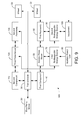
- FIG. 19 is a general block diagram of a hybrid vehicle drive system that does not include hydraulic drive components and includes electric motors coupled to each of two PTOs coupled to the first prime mover according to an exemplary embodiment.
- FIG. 20 is a general block diagram of a hybrid vehicle drive system that includes a smaller electric motor as a third prime mover to power a hydraulic pump according to an exemplary embodiment.
- FIG. 21 is a general block diagram of a hybrid vehicle drive system that does not include hydraulic drive components and includes electric motors coupled to each of two PTOs coupled to the first prime mover along with an electric motor coupled to the internal combustion engine to power on-board accessories according to an exemplary embodiment.
- FIG. 22 is a general block diagram of a hybrid vehicle drive system in series mode operation in accordance with an exemplary embodiment.
- FIG. 23 is a general block diagram of a hybrid vehicle drive system in a series mode of operation in accordance with an exemplary embodiment.
- FIG. 24 is a general block diagram of a hybrid vehicle drive system in a parallel mode of operation in accordance with an exemplary embodiment.
- FIG. 25 is a general block diagram of a hybrid vehicle drive system in a cruising mode in accordance with an exemplary embodiment.
- FIG. 26 is a general block diagram of a hybrid vehicle drive system in a cruising mode in accordance with an exemplary embodiment.
- FIG. 27 is a general block diagram of a hybrid vehicle drive system when the vehicle is stationary in accordance with an exemplary embodiment.
- FIG. 28 is a general block diagram of a hybrid vehicle drive system when the first prime mover is used to recharge the energy source in accordance with an exemplary embodiment.
- FIG. 29 is a general block diagram of a hybrid vehicle drive system when the first prime mover is used to recharge the energy source in accordance with an exemplary embodiment.
- Hybrid vehicle drive systems according to several possible embodiments are presented.
- One feature of one exemplary embodiment of the hybrid vehicle drive system is that a drive shaft can be powered singly or in any combination by a first prime mover, a second prime mover, and an accessory.
- Preferred embodiments incorporate hydraulic systems into the hybrid vehicle drive system for optimal energy storage and usage.
- motor refers to a motor/generator or motor/pump and is not limited to a device that performs only motor operations.
- a hybrid vehicle drive system includes an internal combustion engine connected through a transmission to drive wheels of a vehicle, with the transmission having a power take off (PTO), wherein the drive system is retrofitted by the steps of:
- VMCS vehicle monitoring and control system
- the VMCS controls the parallel hybrid drive system to use the electric motor to supplement drive power to the wheels of the vehicle when the internal combustion engine is driving the wheels and provides regenerative braking when the engine is not delivering power to the wheels whereby the battery in the parallel hybrid drive system is recharged.
- the retrofitting can also include the step of connecting the PTO to a torque converter in the transmission, as well as the step of recharging the energy storage system using an outside electric power source.
- the retrofitting can also include the step of withdrawing auxiliary power from the electric motor when the electric motor is recharging the energy storage system, or the step of disengaging the auxiliary power take off when the electric motor is delivering shaft power to the transmission.
- the VMCS uses a dampening function to reduce vibration in the PTO when switching between supplemental drive power and regenerative braking.
- the VMCS preferably also monitors accelerator pedal position, engine throttle position, battery voltage, vehicle speed, and/or torque request to determine the amount and frequency of power being applied to the PTO for maintaining vehicle drivability and to optimize overall efficiency.
- the hybrid system can use a high voltage DC connection center between the energy storage system and an inverter for the electric motor, to control electric power flow between the energy storage system and the electric motor, which can also recharge the energy storage system during park or neutral position of the transmission.
- the VMCS also provides a method for tuning the amount of power provided for launch assist and regenerative braking power applied in the forward and/or reverse direction, wherein further the VMCS has a tuning chart for the setting provided for each gear, the settings including pedal position vs. positive or negative torque applied, battery voltage vs.
- the system also shifts through each gear, and the transmission provides a signal over the vehicle data network to, wherein the VMCS, in order to provide advanced notice of a shift event, and wherein further based upon this information and the pedal position, so that the VMCS can increase or decrease the power provided to the electric motor, allowing for smoother and more efficient shifting, thereby enhancing the vehicle ride and reducing fuel consumption.
- the VMCS also preferably interfaces with any original equipment manufacturers (OEM) vehicle data system in order to eliminate or reduce regenerative braking based on anti-lock or traction control events.
- OEM original equipment manufacturers
- any unneeded drive system components other than a first prime mover can be entirely disconnected from the drive train, reducing inefficiencies and wear in situations where the different portions of the system do not need to interact, such as when a drive shaft is solely driven by the first prime mover, or when a vehicle using the system is stationary and a second prime mover and accessory are not being driven by the first prime mover.
- an optional clutch between the first prime mover and the transmission can be used to reduce inefficiencies during regenerative braking by removing the first prime mover from the system when vehicle braking occurs.
- the accessory e.g., hydraulic pump, pneumatic pump, electric motor, etc.
- the accessory can be powered singly or in any combination by the first prime mover, the second prime mover, energy from braking, or energy stored in a second rechargeable energy source (e.g., battery, ultra capacitor, hydraulic accumulator, etc.).
- a second rechargeable energy source e.g., battery, ultra capacitor, hydraulic accumulator, etc.
- the presence of a second rechargeable energy source also can obviate the need for a complicated pump control system when the accessory is a hydraulic pump.
- the pump is a variable volume displacement pump, further simplification is possible because a clutch may not be needed between the second prime mover and the pump.
- Other types of pumps can also be used.
- the pump can be an inexpensive gear pump.
- a first rechargeable energy source connected to the second prime mover can be recharged in one or more modes. These modes include: the second prime mover using power from the first prime mover; the second prime mover using power from regenerative braking; the accessory, using energy stored in the second rechargeable energy source to operate the second prime mover; an auxiliary power unit connected to the first rechargeable energy source; an engine alternator, when present (the alternator can be increased in capacity to allow for this additional charge while driving or idle); or from an external power source, such as being directly plugged into an external power grid.
- the second prime mover can draw upon this power stored in the first rechargeable power source before daily operation of the vehicle (e.g., after overnight charging), when the vehicle is stopped, or in other situations. In such situations, the second prime mover would operate the accessory to pre-charge or pressurize the second rechargeable energy source before the energy is needed, which would provide higher density power storage when the second rechargeable power source is a hydraulic accumulator, among other advantages.
- a higher density energy storage device is intended to provide more available power at low revolutions per minute (RPM) operation and an overall lower mass system.
- hybrid vehicle drive systems according to several exemplary embodiments are shown. Various features of these embodiments can be employed in other embodiments described herein.
- an exemplary embodiment of a hybrid vehicle drive system 10 can be employed on any type of vehicle.
- the vehicle can be any type of light, medium, or heavy duty truck.
- the vehicle is a truck that employs hydraulic systems such as a boom truck.
- the vehicle can be any type of platform where hybrid systems are employed.
- the vehicle may have a wide variety of axle configurations including, but not limited to a 4 ⁇ 2, 4 ⁇ 4, or 6 ⁇ 6 configuration.
- the vehicle is truck such as an International 4300 SBA 4 ⁇ 2 truck.
- the vehicle includes an IHC MaxxforceDT engine with an output of 255 HP and 660 lbs. of torque.
- the vehicle further includes an Allison 3500_RDS_P automatic transmission.
- the vehicle has a front gross axle weight rating (GAWR) of 14,000/12,460 lbs, a rear GAWR of 19,000/12,920 lbs., and a total GAWR of 33,000/25,480.
- the vehicle includes a hydraulic boom.
- the vehicle boom has a working height of approximately 54.3 feet, a horizontal reach of 36.0 feet, an upper boom has an extension of approximately 145 inches.
- the lower boom may travel between approximately 0 degrees and 87 degrees from horizontal.
- the upper boom may have a travel between approximately ⁇ 20 degrees and 76 degrees from horizontal.
- the vehicle may further include a hydraulic platform rotator, a hydraulic articulating jib and winch (e.g., with a capacity of 1000 lbs.), a hydraulic jib extension, hydraulic tool outlets, an on-board power charger providing 5 kW at 240 VAC, and electric air conditioning with a capacity of 5,000 BTU.
- a hydraulic platform rotator e.g., with a capacity of 1000 lbs.
- a hydraulic jib extension e.g., with a capacity of 1000 lbs.
- hydraulic tool outlets e.g., with a capacity of 1000 lbs.
- an on-board power charger providing 5 kW at 240 VAC
- electric air conditioning with a capacity of 5,000 BTU.
- the above referenced power, boom, and types of components are exemplary only.
- System 10 includes a first prime mover 20 (e.g., an internal combustion engine, such as a diesel fueled engine, etc.), a first prime mover driven transmission 30 , a component 40 (e.g., a power take-off (PTO), a transfer case, etc.), a second prime mover 50 (e.g., a motor, such as an electric motor/generator, a hydraulic pump with a thru-shaft, etc.), and an accessory 60 (e.g., a hydraulic pump, such as a variable volume displacement pump, etc.). In certain embodiments, accessory 60 can act as a third prime mover as described below.
- Transmission 30 is mechanically coupled to component 40 .
- Component 40 is coupled to second prime mover 50 .
- Second prime mover 50 is coupled to accessory 60 .
- second prime mover 50 is a 50 kW electric motor.
- second prime mover 50 may generate 30 kW continuously or as much as 75 kW at peak times.
- the above referenced power parameters are exemplary only.
- Second prime mover 50 may be further used to power various on-board components such as compressors, water pumps, cement mixer drums, etc.
- accessory 60 is embodied as a hydraulic motor and includes a through shaft coupled to component 40 embodied as a PTO.
- the through shaft is also coupled to the shaft of the mover 50 embodied as an electric motor.
- electric motor includes the through shaft that is coupled to the PTO and the pump.
- system 10 also includes a first rechargeable energy source 70 (e.g., a battery, a bank of batteries, a fuel cell, a capacitive cell, or other energy storage device), an Auxiliary Power Unit (APU) 80 (e.g., an internal combustion engine, possibly fueled by an alternative low emission fuel (e.g., bio-mass, natural gas, hydrogen, or some other fuel with low emissions and low carbon output), and a generator, a fuel cell, etc.), a second rechargeable energy source 90 (e.g. a hydraulic accumulator, ultra capacitor, etc.), and onboard or external equipment 100 (e.g., hydraulically operated equipment, such as an aerial bucket, etc.).
- APU Auxiliary Power Unit
- APU Auxiliary Power Unit
- second rechargeable energy source 90 e.g. a hydraulic accumulator, ultra capacitor, etc.
- onboard or external equipment 100 e.g., hydraulically operated equipment, such as an aerial bucket, etc.
- First rechargeable energy source 70 is coupled to second prime mover 50 and provides power for the operation of second prime mover 50 .
- First rechargeable (e.g., pressurized or rechargeable) energy source 70 may include other auxiliary components (e.g., an inverter provided for an AC motor, a DC-to-DC converter to charge a DC system, an inverter for power exportation to a power grid or other equipment, controllers for motors, a charger, etc).
- APU 80 is coupled to first rechargeable energy source 70 and provides power to first rechargeable energy source 70 .
- second renewable energy source 90 is a hydraulic system with a high pressure portion (e.g., an accumulator) and a low pressure component (e.g., a reservoir tank).
- Second rechargeable energy source 90 is coupled to accessory 60 and provides stored power for accessory 60 .
- Onboard or external equipment 100 can be coupled to accessory 60 or second rechargeable energy source 90 and operate using power from either accessory 60 or second rechargeable energy source 90 .
- onboard or external equipment 100 is coupled through second rechargeable energy source 90 to accessory 60 .
- APU 80 may also provide power to both second renewable energy source 90 and first rechargeable energy source 70 when high hydraulic loads are required.
- APU 80 and second renewable energy source 90 may both provide power to hydraulically operated equipment 100 .
- component 40 is a PTO designed to engage or disengage while the transmission is moving via a clutch mechanism.
- the PTO can be a street side or curb side PTO.
- Component 40 can be disengaged from transmission 30 when first prime mover 20 exceeds the maximum operating RPM of any component connected through component 40 .
- component 40 can be disengaged if first prime mover 20 exceeds the maximum operating RPM of accessory 60 .
- all components connected through component 40 can operate throughout the RPM range of first prime mover 20 , and component 40 can be engaged continuously.
- component 40 can be disengaged during high speed steady driving conditions to reduce friction and wear on system 10 .
- transmission 30 may be modified to incorporate component 40 and optionally incorporate second prime mover 50 directly into transmission 30 .
- Component 40 embodied as a PTO, may optionally include a PTO shaft extension.
- a PTO shaft extension is described in U.S. Pat. No. 6,263,749 and U.S. Pat. No. 6,499,548 both of which are incorporated herein by reference.
- Component 40 can have a direct connection to transmission 30 .
- Component 40 may interface with transmission 30 in a way that there is a direct coupling between mover 20 , component 40 , and transmission 30 .
- component 40 may interface with transmission 30 in a way that the interface directly couples component 40 to the torque converter of transmission 30 .
- the torque converter may be in mechanical communication with mover 20 , but rotating at a different speed or may rotate at the same speed as mover 20 if it is locked up.
- a clutch mechanism can be employed to properly engage and disengage component 40 .
- component 40 is a PTO that has an internal clutch pack, such as a hot shift PTO.
- a hot shift PTO can be used when frequent engagements of the PTO are required, often with automatic transmissions.
- second prime mover 50 can be operated at the same RPM as first prime mover 20 prior to the engagement of component 40 . This is intended to reduce wear on the clutch mechanism if component 40 has a 1:1 ratio of input speed to output speed. If other ratios for component 40 are used, the RPM of first prime mover 20 or second prime mover 50 can be adjusted accordingly prior to engagement to insure that input and output speed match the ratio of the component to reduce wear on the clutch mechanism.
- second prime mover 50 can operate to provide power to a drive shaft 32 via transmission 30 .
- first prime mover 20 provides power to drive shaft 32 through transmission 30 .
- Second prime mover 50 provides additional or alternative power to drive shaft 32 through component 40 and transmission 30 .
- Drive shaft 32 provides power to two or more wheels 33 used to provide forward and backward momentum to the vehicle.
- second prime mover 50 can optionally provide the sole source of power to drive shaft 32 .
- second prime mover 50 can provide additional power to drive shaft 32 during vehicle acceleration.
- second prime mover 50 can operate using power from first rechargeable energy source 70 .
- first rechargeable energy source 70 can be charged or powered by second prime mover 50 , APU 80 or another suitable source (e.g., the vehicle alternator, the power grid, etc.).
- Optional APU 80 can be used to power first rechargeable energy source 70 when the vehicle is driving up a grade, as well as other situations. This use is intended to improve vehicle performance, particularly when the power requirements of the vehicle exceed the power available from first prime mover 20 , first rechargeable energy source 70 , and second rechargeable energy source 90 .
- the presence of APU 80 is intended to allow for a smaller first prime mover 20 .
- APU 80 is of a type that produces lower emissions than first prime mover 20 .
- APU 80 is intended to enable a vehicle using system 10 to meet various anti-idle and emission regulations.
- system 10 is configured to automatically engage APU 80 or first prime mover 20 through component 40 or accessory 60 to charge first rechargeable energy source 70 when the stored energy decreases to a certain amount.
- the permissible reduction in stored energy can be determined based upon a user selectable switch.
- the switch specifies the method of recharging first rechargeable energy source 70 from an external power grid.
- a user can select between 220-240V recharging, 110-120V recharging, and no external power source available for recharging. For the different voltages, the amount of power that can be replenished over a certain period of time (e.g., when connected to an external power grid overnight) would be calculated. Beyond that amount of power usage, first prime mover 20 , or APU 80 is engaged to charge or provide power to first rechargeable energy source 70 . If no external power source is available, first prime mover 20 or APU 80 can be automatically engaged during regular finite periods, calculated to minimize idle time. In one embodiment, APU 80 and/or optionally first rechargeable energy source 70 can provide power to an external power grid 200 , also known as vehicle to grid (V2G) power sharing. This is intended to provide low-emission power generation and/or reduce requirements to generate additional grid power during peak loads on the grid.
- V2G vehicle to grid
- a user may only select between two settings, one setting to select charging using a grid and the other setting to select charging without using an external power grid.
- the controller would monitor state of charge of the batteries and control recharging differently for each setting. If no external charging from a power grid is selected, system 10 may allow the state of charge of first rechargeable energy source 70 (batteries) to drop to a threshold (as an example 30%), then the controller would cause either first prime mover 20 or the optional APU 80 to be engaged to charge batteries to a predetermined level (as an example 80%) to minimize the frequency that first prime mover 20 or APU 80 must be started. Or different levels of discharge and recharging may be selected to minimized idle time. System 10 may occasionally recharge batteries to 100% of charge to help condition the batteries.
- the controller may allow the state of charge of first renewable energy source to drop to a threshold (as an example 30%), then the controller would cause either first prime mover 20 or optional APU 80 to be engaged to charge batteries to a predetermined level that is lower (as an example 50%).
- the lower level allows the external power grid to recharge a greater amount of first rechargeable energy source 70 when vehicle can be plugged in or charged by the external power grid, reducing the fuel consumption of prime mover 70 or optional APU 80 .
- External power grid 200 allows first rechargeable energy source 70 to be recharged with a cleaner, lower cost power compared to recharging first rechargeable energy source 70 with first prime mover 20 .
- Power from an external power grid may be provided at a fraction of the cost of power provided from an internal combustion engine using diesel fuel.
- first rechargeable energy source 70 can be recharged from an external power grid 200 in approximately 8 hours or less.
- second rechargeable energy source 90 is utilized, and provides power to accessory 60 . Additional or alternative power can be provided to drive shaft 32 by accessory 60 .
- accessory 60 can provide power to drive shaft 32 until second rechargeable energy source 90 is discharged.
- accessory 60 can provide additional power to drive shaft 32 during vehicle acceleration.
- Accessory 60 provides power to drive shaft 32 through second prime mover 50 , component 40 , and transmission 30 .
- the combination of power provided to drive shaft 32 by second prime mover 50 and accessory 60 is intended to allow for the use of a smaller first prime mover 20 which provides the best use of stored energy and reduces the overall system mass.
- accessory 60 only receives power from second prime mover 50 or from first prime mover 20 through component and does not provide power to drive shaft 32 .
- Accessory 60 may power equipment directly.
- an optional clutch can be coupled between first prime mover 50 and accessory 60 or between component 40 and second prime mover 50 .
- the clutch is disengaged when the vehicle is stationary so second prime mover 50 can turn accessory 60 without unnecessarily driving component 40 .
- a variety of control systems can be utilized to control the various components (clutches, motors, transmissions, etc.) in system 10 .
- Electronic control systems, mechanical control systems, Vehicle Monitoring and Control System (VMCS), and hydraulic control systems can be utilized.
- VMCS Vehicle Monitoring and Control System
- a controller can be provided to indicate a request to operate an accessory or other equipment.
- a controller similar to the controller in U.S. Pat. No. 7,104,920 incorporated herein by reference can be utilized.
- the controller is modified to communicate by pneumatics (e.g., air), a wireless channel, or fiber optics (e.g., light) for boom applications and other applications where conductivity of the appliance is an issue.
- the control system can utilize various input criteria to determine and direct the amount of power required or to be stored, the input criteria can input operator brake and acceleration pedals, accessory requirements, storage capacity, torque requirements, hydraulic pressure, vehicle speed, etc.
- a control system may control the torque and power output of second prime mover 50 and accessory 60 so that component 40 , second prime mover 50 and accessory 60 are operated within the allowable torque and power limitations of each item so that the sum of second prime mover 50 and accessory 60 do not exceed component 40 or exceed capacity of transmission 30 , such as capacity of transmission power takeoff drive gear rating or exceed capacity of transmission maximum turbine torque on an automatic transmission.
- the controller may monitor and control additional input torque from the prime mover, or input torque of the prime mover after multiplication by the torque converter, along with that from other prime movers or accessories to ensure that the turbine torque limit is not exceeded or other internal torque ratings of components within an automatic transmission or an autoshift manual transmission, or a manual transmission.
- the torque and power output of second prime mover 50 and accessory 60 may also be controlled using an input from the driver and/or from a power train control system. If two components are used as described in other embodiments, the torque and power output of the second and third prime mover and optional accessory or accessories may be controlled so that the transmission power takeoff drive gear rating with two power takeoffs is not exceeded or that the capacity of transmission maximum turbine torque on an automatic transmission, or other torque rating of an internal component within a transmission of different kind, such as an autoshift manual or manual transmission is not exceeded.
- a control system may be used for other purposes (e.g., coupling component 40 to transmission 30 ; monitoring the charge status of first rechargeable energy source 70 and second rechargeable energy source 90 ; monitoring and managing the thermal status of various components (e.g., prime movers, rechargeable energy sources, electronics, etc.); operating first prime mover 20 , second prime mover 50 , and accessory 60 to replenish energy in first rechargeable energy source 70 and second rechargeable energy source 90 and/or supply power to equipment 100 ; operate APU 80 as needed; or control other functions).
- Information on the status of the system such as operating efficiency, status of rechargeable energy sources, and certain operator controls may be displayed or accessed by the driver.
- APU 80 charges or provides power to first rechargeable energy source 70 when necessary.
- APU 80 can include a generator powered by an internal combustion engine. The generator can be connected to first rechargeable energy source 70 through a power converter, AC/DC power inverter or other charging system.
- First rechargeable energy source 70 provides power to second prime mover 50 .
- the operation of second prime mover 50 operates accessory 60 .
- Accessory 60 provides power to on-board or external equipment 100 .
- First rechargeable energy source 70 and/or APU 80 may provide all the power for system 10 when the vehicle is stationary and first prime mover 20 is turned off (e.g., in an idle reduction system). If second prime mover 50 is not coupled to drive shaft 32 and instead provides power to accessory 60 (e.g., in an idle reduction system), system 10 may include a simplified control and power management system.
- component 40 may be mechanically coupled to and first prime mover 20 may be operated periodically to provide power to second prime mover 50 through transmission 30 and component 40 .
- Second prime mover 50 recharges first rechargeable energy source 70 and/or powers accessory 60 .
- Accessory 60 can recharge second rechargeable energy source 90 or operate other equipment.
- system 10 is configured as an idle reduction system that can provide power to vehicle loads such as HVAC, computers, entertainment systems, and equipment without the need to idle the engine continuously.
- system 10 uses an electric motor (e.g., prime mover 50 ) to power a hydraulic pump (e.g., accessory 60 ) for the operation of hydraulic equipment (e.g., aerial buckets, hydraulically powered compressors, etc.).
- the electric motor may directly power a compressor.
- the electric motor can be configured to only operate when there is a demand for hydraulic flow or the need to operate other mechanically coupled equipment to conserve energy within first rechargeable energy source 70 .
- the electric motor can be activated by a controller that receives a signal sent through fiber optics or a signal sent through other means.
- mover 20 is not engaged with component 40 when mover 50 is used to power a pump or other mechanically coupled equipment 100 .
- component 40 PTO
- the PTO may be modified to allow shaft 32 to spin with low resistance.
- a PTO can be chosen with a feature that normally limits movement of the PTO when not engaged, this feature can be disabled when the electric motor is used to power the hydraulic pump. This concept also applies to “operating mode” for hybrid system process below discusses with reference to FIGS. 3 and 4 . This type of idle reduction can be used when the vehicle is stationary.
- Batteries e.g., rechargeable energy source 70 provide energy for the electric motor. After the batteries are depleted, an external power grid is used to recharge the batteries.
- the electric motor may operate continuously, eliminating the need for a controller to turn motor on and off based upon demand.
- Such a system may be coupled to a variable volume displacement pump to reduce flow when demand for hydraulic flow is low, resulting in lower consumption of power from the rechargeable energy source. This same method of continuous operation can also be used for hybrid system configurations.
- the batteries may be thermally corrected during charging. Thermal correction may be needed if the temperature of the battery exceeds a certain threshold.
- a cooling system either external to the vehicle or internal to vehicle may be used, such that coolant is circulated to reduce heat or the battery case can be ventilated with cooler air to dissipate heat, possibly with a powered ventilation system.
- a second pump may also be connected to a PTO (as shown in FIG. 9 ).
- First prime mover 20 may be started and used to recharge by engaging component 40 to transmission and operating second prime mover 50 as a generator to recharge first rechargeable energy source batteries. If there is insufficient energy to operate the electric motor driven hydraulic pump, the vehicle engine is started, PTO engaged and the second pump is used to power the equipment.
- the second pump can be used when the hydraulic power requirements exceed the power output of the electric motor coupled to the hydraulic pump.
- prime mover 50 could directly power the first accessory (hydraulic pump) and the second prime mover could be made not to operate as a generator. Not operating second prime mover as a generator may reduce system complexity and reduce cost.
- first rechargeable energy source 70 provides power to electrical systems of the vehicle such as “hotel loads” (e.g., HVAC, lighting, radio, various electronics, etc.). In yet another embodiment, first rechargeable energy source 70 charges a main crank battery of the vehicle. The main crank battery can be isolated from system 10 . First rechargeable energy source 70 may also be used in other configurations that use 100% electric propulsion for certain periods to power additional vehicle systems such as power steering, brakes and other systems normally powered by first prime mover 20 .
- second prime mover 50 provides power to external devices directly or through an additional rechargeable energy source and an associated inverter. Utilizing second prime mover 50 to power external devices is intended to lessen the need for an additional first prime mover 20 powered generator.
- a sophisticated control system e.g., a pump control system utilizing fiber optics, etc.
- accessory 60 is a variable volume displacement pump. Accessory 60 can operate continuously, only providing flow if there is a demand. When no demand is present, accessory 60 provides little or no additional friction or resistance within the system.
- First rechargeable energy source 70 and/or APU 80 may provide power for system 10 when the vehicle is stationary and first prime mover 20 is turned off (e.g., in an idle reduction system).
- energy source 70 may power accessory 60 .
- second rechargeable energy source 90 is utilized.
- Accessory 60 stores energy in second rechargeable energy source 90 , as shown.
- Second prime mover 50 is engaged to operate accessory 60 (e.g., a hydraulic pump) when the stored energy in second rechargeable energy source 90 (e.g., a hydraulic accumulator) is reduced to a predetermined level.
- the utilization of second rechargeable energy source 90 is intended to reduce operation time of accessory 60 .
- Accessory 60 only needs to operate to maintain energy in second rechargeable energy source 90 .
- On-board or external equipment 100 e.g., any hydraulic equipment
- second rechargeable energy source 90 is powered by second rechargeable energy source 90 .
- a clutch mechanism is used to disengage accessory 60 from second prime mover 50 during vehicle travel when second rechargeable energy source 90 has been fully charged. This is intended to reduce friction on system 10 when second prime mover 50 is needed, but accessory 60 is not.
- Second rechargeable energy source 90 can provide hydraulic power to equipment 100 at a constant system pressure through a pressure reducing valve.
- second rechargeable energy source 90 and two hydraulic motor/pump units are coupled together to provide constant system pressure and flow.
- the first unit e.g., a hydraulic motor
- receives high pressure flow from second rechargeable energy source 90 The first unit is coupled to a second unit (e.g., a pump) which supplies hydraulic power to equipment 100 at a lower pressure.
- Both hydraulic second rechargeable hydraulic circuit and low pressure hydraulic equipment circuit have a high pressure and a low pressure (reservoir or tank) sections.
- a control system may be utilized to maintain constant flow in the low pressure hydraulic equipment circuit as the high pressure flow from the second rechargeable source (accumulator) reduces or varies. The advantage of this configuration is that the energy from the high pressure accumulator is more efficiently transferred to the equipment.
- This configuration also allows independent hydraulic circuits to be used for the propulsion system and for equipment 100 .
- the independent hydraulic circuits allow for fluids with different characteristics to be used in each circuit.
- a hydraulic circuit that may be susceptible to contamination e.g., the equipment circuit
- can be kept separate from the other hydraulic circuit e.g., the propulsion circuit.
- second rechargeable energy source 90 is utilized, and accessory 60 is a hydraulic pump.
- Second rechargeable energy source 90 can include a low pressure fluid reservoir and a hydraulic accumulator. The utilization of second rechargeable energy source 90 obviates the need for a sophisticated pump control system and the associated fiber optics; instead a simpler hydraulic system can be used (e.g., an insulated aerial device with a closed center hydraulic system and a conventional control system, etc.). If the speed of accessory 60 slows due to depletion of on-board power sources, accessory 60 can operate longer to maintain energy in second rechargeable energy source 90 . This is intended to minimize any negative effects on the operation of equipment 100 .
- second prime mover 50 is an AC motor and turns at generally a constant rate regardless of the output volume of accessory 60 (e.g., to create two or more different levels of flow from accessory 60 ).
- second prime mover 50 may provide power to accessory 60 and the speed of second prime mover 50 may be varied by a controller.
- the speed of second prime mover 50 may be varied to reduce the flow of fluid from accessory 60 (e.g., for two speed operation of an aerial device where lower hydraulic flow may be desirable for fine movement of the boom).
- system 10 can provide the advantage of allowing a vehicle to operate at a work site with fewer emissions and engine noise by using an operating mode.
- first prime mover 20 e.g., an internal combustion engine, such as a diesel fueled engine, etc.
- component 40 PTO
- component 40 when disengaged is able to spin freely with little resistance
- power from first renewable energy source 70 and second renewable energy source 90 are used to operate on-board or external equipment 100 and electrical systems of the vehicle such as “hotel loads” (e.g., HVAC, lighting, radio, various electronics, etc.).
- second renewable energy source 90 may be optional and first renewable energy source 70 may directly power to equipment 100 .
- first renewable energy source 70 has a capacity of approximately 35 kWh and is configured to provide enough power to operate the vehicle for a full day or normal operation (e.g., 8 hours).
- first rechargeable energy source 70 can be recharged by other components of system 10 (in addition to other methods).
- First prime mover 20 and second prime mover 50 are preferably operated and synchronized to the same speed (e.g., input and output mechanical communication through component 40 is a one to one ratio).
- Component 40 is preferably engaged to transmission 30 .
- First prime mover 20 provides power to second prime mover 50 through transmission 30 and component 40 .
- Adjustments to second prime mover 50 speed is made if the ratio between first prime mover 20 and second prime mover 50 is not one to one to minimize wear of the clutch in component 40 or to speed of first prime mover 50 .
- Operation of second prime mover 50 recharges first rechargeable energy source 70 to a predetermined level of stored energy.
- This method of recharging first rechargeable energy source 70 is intended to allow continuous system operation in the field without the use of external grid power. This method is further intended to allow continuous operation of equipment 100 during recharging of first rechargeable energy source 70 .
- second prime mover 50 While charging first rechargeable energy source 70 , second prime mover 50 simultaneously operates accessory 60 .
- Accessory 60 provides power to on-board or external equipment 100 .
- component 40 is disengaged from transmission 30 .
- Operation of accessory 60 can continue without the use of first prime mover 20 as shown in FIG. 2 .
- operation of accessory 60 can continue powered in part or in full by prime mover 20 . This may be useful for example, if there is a failure in one of the other components that power accessory 60 . This may also be useful if the power demand from accessory 60 exceeds the power available from second prime mover 50 .
- first prime mover 20 provides supplementary power to or all of the power to equipment 100 (e.g. a digger derrick that may require higher hydraulic flow during digging operations).
- first prime mover 20 to provide supplementary power to equipment 100 during intermittent periods of high power requirement allows system 10 to include a smaller second prime mover 50 that is able to provide enough power for the majority of the equipment operation.
- the control system may receive a signal from the equipment indicating additional power is required beyond that provided by second prime mover 50 . Such a signal may be triggered by the operator, by activation of a function (e.g., an auger release, etc.), by demand in the circuit or component above a predetermined threshold, or by other means.
- a function e.g., an auger release, etc.
- Second rechargeable energy source 90 is utilized. Accessory 60 provides power to second rechargeable energy source 90 .
- on-board or external equipment 100 e.g., hydraulic cylinders, valves, booms, etc.
- external equipment 100 is coupled to second rechargeable energy source 90 , and can be powered by second rechargeable energy source 90 .
- External equipment 100 may also be operated directly by accessory 60 without the use of a second rechargeable energy source 90 .
- This method of recharging first rechargeable energy source 70 and second rechargeable energy source 90 is intended to allow continuous system operation in the field without the use of external grid power. This method is further intended to allow continuous operation of equipment 100 during recharging of first rechargeable energy source 70 and second rechargeable energy source 90 .
- a clutch or other mechanism is used to disengage first prime mover 20 from transmission 30 during vehicle braking. This is intended to maximize the regenerative energy available from vehicle braking.
- the forward momentum of the vehicle provides power from wheels 33 to transmission 30 .
- Transmission 30 may be reduced to a lower gear to increase the RPMS and increase the amount of energy transferred to second prime mover 50 .
- Second prime mover 50 can operate to charge first rechargeable energy source 70 and help slow the vehicle according to principles of regenerative braking Disengaging first prime mover 20 from transmission 30 further reduces the amount of energy transferred back to first prime mover 20 during braking and reduces the need for engine braking.
- the control system for the hybrid components may also monitor chassis anti-lock brake system (ABS) activity. If the chassis anti-lock brake system has sensed possible wheel lock-up and has become active, possibly due to low traction or slippery road conditions, then hybrid regenerative braking is suspended by the hybrid control system.
- the regenerative braking system may be disabled as soon as ABS is active and may remain off for only as long as the ABS is active, or alternatively regenerative braking may remain off for a period of time after ABS is no longer active or regenerative braking may remain off for the remainder of the ignition cycle to eliminate the chance that regenerative braking could adversely affect vehicle handling in low friction, slippery road conditions during the current ignition cycle. At the next ignition cycle, regenerative braking may be reactivated.
- Second rechargeable energy source 90 is utilized. As mentioned above, during vehicle braking, first rechargeable energy source 70 is charged through operation of second prime mover 50 . Accessory 60 can operate to further slow the vehicle, and store energy in second rechargeable energy source 90 , if second rechargeable energy source 90 is not fully charged. In this manner, regenerative braking can be used to simultaneously charge multiple energy storage devices of system 10 . This is intended to allow recharging of both energy storage devices through braking during vehicle travel, among other advantages.
- a clutch can be optionally included between first prime mover 20 and transmission 30 to further improve regenerative braking.
- component 40 is a transfer case.
- Component 40 is coupled to transmission 30 , drive shaft 32 , and second prime mover 50 .
- Energy from regenerative braking bypasses transmission 30 , passing through component 40 to operate second prime mover 50 .
- motive power for drive shaft 32 from second prime mover 50 and accessory 60 bypasses transmission 30 , passing through component 40 .
- Component 40 further allows power from second prime mover 50 to be transferred to drive shaft 32 , assisting, for example, when the vehicle is accelerating.
- a conventional clutch can be placed between drive shaft 32 and component 40 to disconnect drive shaft 32 when the vehicle is parked and to allow second prime mover 50 to charge first rechargeable energy source 70 when transmission 30 is coupled to component 40 and first prime mover 20 is coupled to transmission 30 .
- An optional clutch can also be placed between component 40 and transmission 30 or between transmission 30 and first prime mover 20 . This allows power from regenerative braking to be channeled directly to second prime mover 50 and accessory 60 .
- component 40 is not coupled to second prime mover 50 and accessory 60 can optionally directly power equipment 100 .
- An optional APU 80 can charge first rechargeable energy source 70 and/or second rechargeable energy source 90 as required.
- a second component 110 such as a power take-off (PTO) is coupled to the transmission 30 .
- Accessory 60 may be a hydraulic pump with the capability to produce more power than a single power take-off can transfer to transmission 30 .
- First component 40 and second component 110 are provided to cooperate to transfer more power from second rechargeable energy source 90 to transmission 30 than a single component is able to transfer.
- System 10 further includes a third prime mover 120 (e.g., a motor, such as an electric motor/generator, etc.), and a second accessory 130 (e.g., a hydraulic pump, such as a variable volume displacement pump, etc.).
- Transmission 30 is mechanically coupled to components 40 and 110 .
- Second component 110 is coupled to third prime mover 120 .
- Third prime mover 120 is coupled to second accessory 130 .
- First rechargeable energy source 70 is coupled to third prime mover 120 and provides power for the operation of third prime mover 120 .
- Second rechargeable energy source 90 is coupled to second accessory 130 and provides stored power for second accessory 130 . While FIG. 9 shows a system 10 with both third prime mover 120 and second accessory 130 coupled to second component 110 , according to other exemplary embodiments, either third prime mover 120 or second accessory 130 may be absent. If a clutch is provided between first prime mover 20 and transmission 30 , first component 40 and second component 110 may be configured to drive transmission 30 , possibly without assistance from prime mover 20 or when prime mover 20 is off. At slow speeds, if transmission 30 includes a torque converter which is not locked, the optional clutch may not be needed for components 40 and 110 to transfer power to transmission 30 and move the vehicle.
- an external power grid can be used with an electrical rechargeable energy source.
- Battery size and system software can be modified to charge the battery in the electric grid.
- the software can be modified to use a charge depleting mode if the battery is charged from the grid.
- a high horsepower prime mover 140 (e.g., a motor such as a high output power hydraulic motor, etc.) is coupled to second component 110 in a system 1000 .
- High horsepower prime mover 140 is further coupled to second rechargeable energy source 90 (e.g., one or more accumulators). Second rechargeable energy source 90 is pressurized by accessory 60 during highway speeds or while parked.
- high horsepower prime mover 140 receives power from a PTO to pressurize second rechargeable energy source 90 during regenerative braking Conversely, mover 140 can aid acceleration of the vehicle through component 110 and transmission 30 .
- a clutch can be disposed between first prime mover 20 and transmission 30 for more efficient regenerative braking.
- the embodiment of system 10 shown in FIG. 10 may include a system including second rechargeable energy source 90 and two hydraulic motor/pump units that is configured to provide constant system pressure and flow similar to the system described above.
- the first unit or high pressure motor is provided by high HP prime mover 140 .
- the second unit or low pressure pump (e.g., a variable displacement pump pressure compensated load sensing pump) may be provided between high HP prime mover 140 and second component 110 preferably with a through shaft or other means of mechanical communication.
- the equipment circuit can trigger operation of high HP prime mover 140 .
- a high power prime mover 140 is coupled to second component 110 in a system 1100 .
- High horsepower prime mover 140 is further coupled to an ultra capacitor 150 (e.g., a fast charge and discharge capacitor, etc.) which may include multiple capacitors.
- Capacitor 150 is in turn coupled to first rechargeable energy source 70 .
- First rechargeable energy source 70 is charged by second prime mover 50 during highway speeds or while parked, by auxiliary power unit 80 or by being plugged into the electrical power grid.
- High HP prime mover 140 may also independently recharge first rechargeable energy source 70 .
- APU 80 is optional.
- a second accessory 130 e.g., a hydraulic pump, such as a variable volume displacement pump, etc.
- a high horsepower prime mover 140 e.g., a motor such as a high power electric motor, etc.
- first prime mover 20 e.g., to the crankshaft of an internal combustion engine, such as a diesel fueled engine, etc.
- Second accessory 130 and high horsepower prime mover 140 allow large amount of power to be transmitted to first prime mover 20 .
- First rechargeable energy source 70 is coupled to high horsepower prime mover 140 via capacitor 150 and provides power for the operation of high horsepower prime mover 140 .
- Second rechargeable energy source 90 is coupled to second accessory 130 and provides stored power for second accessory 130 .
- High horsepower prime mover 140 may further be used to assist in cranking first prime mover 20 . Cranking first prime mover 20 may be particularly advantageous when first prime mover 20 is started and stopped frequently (e.g., to reduce idle time).
- High horsepower prime mover 140 may further be a more powerful starter motor. While FIG. 9 shows a system 10 with both second accessory 130 coupled to second component 110 and high horsepower prime mover 140 , according to other exemplary embodiments, either second accessory 130 may be absent or horsepower prime mover 140 may be absent.
- a system 1300 includes a first prime mover 20 (e.g., an internal combustion engine, such as a diesel fueled engine, etc.), a first prime mover driven transmission 30 , a component 40 (e.g., a power take-off (PTO), a transfer case, etc.), a second prime mover 50 (e.g., a motor, such as an electric motor/generator, a hydraulic pump with a thru-shaft, a hydraulic pump without a thru-shaft with second prime mover 50 only connected on one side etc.), and an accessory 60 (e.g., a hydraulic pump, such as a variable volume displacement pump, a hydraulic pump with a thru-shaft etc.).
- Transmission 30 is mechanically coupled to component 40 .
- Component 40 is coupled to accessory 60 .
- Accessory 60 is coupled to second prime mover 50 .
- accessory 60 is a hydraulic pump with a thru-shaft. Coupling the accessory 60 to the component 40 provides several advantages. Hydraulic pumps with thru-shafts are more common and generally less expensive than thru-shaft motors. Further, accessory 60 is generally smaller than second prime mover 50 and allows for a more compact package when coupled to component 40 .
- Second rechargeable energy source 90 is coupled to accessory 60 and provides stored power for accessory 60 .
- Accessory 60 stores energy in second rechargeable energy source 90 during the operation of system 10 (e.g., during cruising or during regenerative braking, etc.).
- Accessory 60 may draw energy from second rechargeable energy source 90 to provide bursts of high horsepower to first prime mover 20 until second rechargeable energy source 90 is exhausted.
- accessory 60 may directly power equipment and second rechargeable energy source 90 may be absent.
- system 1400 may include a clutch 160 coupled to component 40 .
- component 40 may be a PTO with an integral clutch to selectively disconnect component 40 from first prime mover 20 .
- component 40 may still be powered by second prime mover 50 and/or accessory 60 .
- the rotational inertia of component 40 along with any associated frictional losses represent power that is wasted in component 40 .
- Optional clutch 160 allows component 40 to be disengaged from second prime mover 50 and/or accessory 60 .
- Auxiliary Power Unit 80 is optional. Accessory 60 may directly power equipment 100 .
- Source 90 is optional.
- Optional clutch 160 could be used in other configurations where it would be advantageous to completely remove component 60 from second prime mover 80 or accessory 60 .
- system 1500 may include a clutch 165 .
- System 10 as shown in FIG. 15 operates similar to the embodiment of FIG. 10 and includes an accessory 60 (e.g., a hydraulic pump, such as a variable volume displacement pump, etc.) coupled to component 40 .
- accessory 60 may be configured to provide a large amount of power to transmission 30 to augment first prime mover 10 .
- accessory 60 may transfer additional power to transmission 30 to facilitate accelerating the vehicle.
- Accessory 60 may operate with or without an electrical motor as shown in FIG. 10 .
- Clutch 165 is coupled to first prime mover 20 and transmission 30 .
- Clutch 165 is configured to selectively disengage first prime mover 20 from transmission 30 .
- the rotational inertia of first prime mover 20 along with any associated frictional losses represent energy that is wasted in first prime mover 20 and reduces the efficiency of regenerative braking in system 10 .
- Disengaging first prime mover 20 from the rest of system 1500 allows for more energy to be captured during regenerative braking.
- system 1600 may include both a first component 40 such as a PTO, and a second component 110 such as a transfer case coupled to transmission 30 .
- energy from regenerative braking bypasses transmission 30 , passing through component 110 to operate accessory 60 .
- motive power for drive shaft 32 from accessory 60 bypasses transmission 30 , passing through component.
- Component 110 further allows power from accessory 60 to be transferred to drive shaft 32 , assisting, for example, when the vehicle is accelerating.
- Transmission 30 is further mechanically coupled to component 40 .
- Component 40 is coupled to second prime mover 50 .
- Second prime mover 50 may provide power to a second accessory 65 to pressurize second rechargeable energy source 90 when the vehicle is parked or moving at a constant speed. Second rechargeable energy source 90 provides additional power during the acceleration of the vehicle.
- System 10 may optionally include a clutch between first prime mover 20 and transmission 30 and/or between transmission 30 and component 110 .
- system 1600 may further include a third component 180 such as a PTO, a third prime mover 190 , and a fourth prime mover 195 .
- Third prime mover 190 is coupled to third component 180 .
- Third prime mover 190 is coupled to first rechargeable energy source 70 configured to charge first rechargeable energy source 70 .
- second prime mover 50 may draw power from first rechargeable energy source 70 while first rechargeable energy source 70 continues to be charged by third prime mover 190 .
- Fourth prime mover 195 may be a larger starter motor and may be provided for first prime mover 20 to assist with low speed torque and quick starts of first prime mover 20 . The large starter motor can also reduce unnecessary idle.
- First prime mover 20 may be started and stopped to reduce unnecessary idling.
- Mover 195 , mover 190 , and component 180 are optional. Clutches can be placed between mover 20 and transmission 30 and between transmission 30 and component 110 .
- the interface between mover 50 and accessory 65 can be by a one way or two way interface.
- system 1800 may include both a first component 40 and a second component 110 such as a PTO coupled to transmission 30 , and a third component 210 such as multi-input/output drive coupled to first component 40 and second component 110 .
- Third component 210 may be a hydraulic drive such as manufactured by Funk Manufacturing Co. and distributed by Deere & Company. Third component is further coupled to a second prime mover 50 .
- Second prime mover 50 may be an electric motor with the capability to produce more power than a single power take-off can transfer to transmission 30 .
- First component 40 , second component 110 , and third component 210 are provided to cooperate to transfer more power from second prime mover 50 to transmission 30 than a single component is able.
- system 1900 may include both a first component 40 and a second component 110 such as a PTO coupled to transmission 30 .
- System 10 further includes a second prime mover 50 (e.g., a motor, such as an electric motor/generator, etc.), and a third prime mover 220 (e.g., a motor, such as an electric motor/generator, etc.), coupled to first component 40 and a second component 110 , respectively.
- a first rechargeable energy source 70 is coupled to second prime mover 50 and third prime mover 220 and provides power for the operation of second prime mover 50 and a third prime mover 220 .
- Clutch 165 can disengage first prime mover 30 , allowing the vehicle to be driven in an all electric mode if other vehicle systems (e.g., HVAC system, braking, power steering, etc.) are also electrically driven.
- the all electric mode may also be possible in other system configurations (as shown in FIG. 6 ).
- the all electric mode saves fuel by allowing first prime mover 20 to be off when not needed such as at low speeds or when the vehicle is stopped.
- transmission 30 may be constructed such that independent component input/output gears are used, one for each component 40 and 110 .
- a clutch located in transmission 30 and in between input/output gears for component 40 and 110 could allow series/parallel operation by operating first prime mover 20 , engaging clutch 165 and driving one of the component input/output gears causing either second prime mover 50 or third prime mover 220 to act as a generator.
- the clutch in transmission 30 disengages the other component input/output gear from the other input/output gear coupled to component 40 , 110 that interfaces with prime mover 50 that acts as a generator.
- the remaining component input/output gear is coupled to the other gears in transmission 30 that transmit power to drive shaft 32 , possibly through another clutch internal to the transmission that is engaged.
- the remaining prime mover acts as a motor and powers transmission 30 through the component that is mechanically coupled to the input/output gear.
- prime mover 20 may operate at a more efficient speed and power range, independent of vehicle speed, or prime mover 20 may be turned off completely to further reduce fuel consumption.
- the disengaged prime mover may be synchronized in speed with the disengaged prime mover or prime movers 20 and then also coupled to transmission 30 to provide the needed additional power.
- the engaged prime over or transmission, making adjustments in speed to adapt to the ratio of the input to output gearing of the component (PTO).
- an optional APU could charge first rechargeable energy source 70 while first prime mover 20 is kept off and the vehicle is operated in a series hybrid configuration in which clutch 165 is disengaged.
- the APU is preferably a low emissions power source using a low carbon fuel. Such a configuration would be useful in an urban area requiring low emissions.
- vehicle systems e.g., HVAC, braking, power steering, etc. are operated electrically when first prime mover 20 is off and the vehicle is being driven.
- system 2000 may be similar to the embodiment shown in FIG. 1 .
- second prime mover 50 e.g., a motor, such as an electric motor/generator, etc.
- accessory 60 e.g., a hydraulic pump, such as a variable volume displacement pump, etc.
- a third prime mover 230 such as a smaller electric motor/generator is provided.
- Third prime mover 230 is coupled to first rechargeable energy source 70 and provides power to accessory 60 .
- third prime mover 230 is a 10-60 hp electric motor, more preferably a 20-40 hp electric motor.
- system 2100 may be similar to the embodiment shown in FIG. 1 .
- a fourth prime mover 240 may be coupled to first prime mover 20 with a clutch 245 (e.g., to the crankshaft of the internal combustion engine). The coupling may be direct to the crankshaft or through a belt or through a shaft.
- Fourth prime mover 240 may be, for example, an electric motor that provides power to one or more accessories 250 such as a cooling fan for first prime mover 20 , power steering pumps, an HVAC system, brakes, etc.
- it may be an integrated starter generator, optionally capable of regenerative braking.
- System 2100 as shown in FIG. 21 is able to function in several modes, depending on the needs of the vehicle.
- System 10 can be configured as a combination series/parallel hybrid.
- first prime mover 20 may be turned off and clutch 165 , disengaged prime movers 50 and 220 may provide the power to drive wheels 33 .
- Movers 50 and 220 can be attached to a hydraulic pump.
- movers 50 and 120 can be integrated with a hydraulic pump as a single unit sharing a shaft.
- each of prime movers 50 and 120 are able to provide at least 100 hp so that 200 hp of power are transmitted to transmission 30 to drive wheels 33 .
- first prime mover 20 may be turned on. The speed of the output from first prime mover 20 is synchronized to the desired RPMs. Clutch 165 is engaged to couple first prime mover 20 to transmission 30 in addition to prime movers 50 and 120 . If the vehicle requires even more power to drive shaft 32 , clutch 245 may be engaged so that fourth prime mover 240 provides additional power to crankshaft of first prime mover 20 . Fourth prime mover 240 may simultaneously provide power to one or more accessories 250 . Using prime movers 50 , 220 and 240 to supplement the power driving wheels 33 allows a smaller, more efficient first prime mover 20 to be used in system 10 .
- Fourth prime mover 240 can drive accessories 240 via belts and/or pulleys and/or shafts and/or gears can be mechanically coupled to first prime mover 20 through clutch 245 via belts, shafts, gears and/or pulleys.
- Prime mover 240 can be an electric motor with a through shaft.
- the through shaft can drive belts and/or pulleys for accessories (e.g., HVAC, fan, steering, pumps, brakes, etc.)
- Clutch 165 may be integrated with the transmission (as in a manual transmission or in an auto-shift transmission).
- clutch 165 may be in between the torque converter and the ICE or integrated into the transmission and placed between the torque converter and the input gear for the PTO (for those transmissions that utilize a PTO input gear independent of the torque converter).
- the integration and/or location of clutch 165 as described may be used for other embodiments shown in other diagrams in which a clutch can be placed in between the ICE and the transmission.
- first prime mover 20 is a relatively small internal combustion engine, it may not be able to provide all the power to drive wheels and regenerate rechargeable energy source 70 .
- clutch 165 is disengaged and clutch 245 is engaged so that first prime mover 20 only drives accessories 250 and third prime mover 240 which, in turn, acts as a generator to charge rechargeable energy source 70 .
- Prime movers 50 , and 120 provide power to drive wheels 33 .
- Clutch 245 may disconnect first prime mover 20 from fourth prime mover 240 and fourth prime mover 240 may provide power for accessories 250 .
- engine coolant may be circulated through a heating element (not shown).
- the ICE can then be turned off to eliminate fuel consumption and reduce emissions if first rechargeable energy source has enough energy to power other prime movers.
- a control system would assess various inputs to the system and adjust output of various devices, for example monitoring factors such as, energy levels, power demand, torque, control inputs, speeds, temperatures and other factors to determine appropriate operation of prime movers, activation of clutches and other devices for optimal efficiency and performance.
- the heated coolant would then be circulated back to first prime mover 20 .
- the heated coolant may also be used to warm rechargeable energy source 70 or other on-board batteries when the ambient air is cold. The warmer for the engine block and/or batteries could be used on other embodiments.
- System 2100 as illustrated in FIG. 21 advantageously can utilize a parallel hybrid configuration with assist from fourth prime mover 240 (e.g., accessory electric motor), first prime mover 20 (ICE), second prime mover 50 , and third prime mover 220 .
- fourth prime mover 240 e.g., accessory electric motor
- first prime mover 20 ICE
- second prime mover 50 e.g., second prime mover 50
- third prime mover 220 e.g., third prime mover 220 .
- transmission 30 can include a clutch (e.g. internal or external clutch 165 ).
- components 40 and 110 can be utilized to launch the vehicle and once the input shaft is close to or at the same speed as the engine drive shaft, the clutch can be engaged to couple prime mover 20 to transmission 30 . This method can also be used for other embodiments in which a clutch is used to engaged the prime mover with the transmission.
- system 2100 in FIG. 21 can be provided as only a single PTO system.
- the use of two PTOs allows more power to be provided to transmission 30 .
- system 2100 of FIG. 21 can be arranged so that a parallel hybrid configuration is assisted from mover 220 and mover 50 during acceleration.
- power can be provided through components 40 and 110 via motors 50 and 220 with prime mover 20 off.
- Fourth prime mover 240 can be a multitude of electric motors for powering individual accessories. Clutch 245 and mover 240 can be connected to the front or other locations of prime mover 20 and could be used in other configurations with reference to FIGS. 1-20 .
- electric only acceleration can use standard drive train components and does not produce emissions.
- the use of prime mover 240 powered through source 70 for movers 220 and 50 reduces emissions.
- system 2100 as illustrated in FIG. 21 can also be configured to provide series electric only acceleration.
- Mover 20 is used to charge first rechargeable energy source 70 (e.g., batteries) and is not directly coupled to transmission 30 or is disconnected from transmission 30 via clutch 165 .
- Mover 240 provides power to accessories 250 .
- mover 20 can be configured to operate at most efficient RPM and load.
- motor 240 has a thru-shaft and can act as a generator while mover 20 powers accessories.
- Such a system would have advantages in stop and go type applications where electric motors can store energy during braking and accelerate vehicle without having to change the operating RPM of mover 20 .
- system 2100 as illustrated in FIG. 21 can also be operated in a ICE only cruise mode.
- ICE prime mover e.g., mover 20
- electric motors e.g., movers 220 and 50
- Such mode provides best constant power at cruising speeds.
- mover 20 can be directly coupled or coupled through clutch 165 to transmission 30 to provide best efficiency when mover 20 (ICE) can operate at a steady state and in an efficient RPM and load range. All unnecessary hybrid components can be disconnected during ICE only cruise mode, as well as any unnecessary loads.
- electric motors or hydraulic motors
- system 2100 as illustrated in FIG. 21 can also be provided in a mode in which highway speed is maintained by mover 20 and hybrid components are temporarily engaged to accelerate or slow the vehicle.
- An ICE (mover 20 ) can be used for base cruise power and one or more electric or hydraulic motors are engaged as needed for additional acceleration or to slow the vehicle.
- components 110 and 40 e.g., PTOs
- PTOs can be disengaged to remove unnecessary resistance of unneeded hybrid components.
- such a configuration allows a smaller horsepower engine to be used in optimal range for maximum efficiency and reduces large swings required in outputs from mover 20 (e.g., the engine operates less efficiently when required to provide power to provide large transient loads or when power output is much higher or lower than its optimal range).
- mover 50 can include a pump or a pump can be placed in between mover 50 and first component 40 .
- the hydraulic pump could be placed after or behind mover 50 .
- power from source 70 can be utilized to drive pump for hydraulic components using mover 50 .
- Such configuration would be advantageous when the vehicle is stationary as power from the batteries (e.g., source 70 ) is utilized to operate electric motors and hydraulic pumps.
- system 2100 illustrated in FIG. 21 can be operated in a mode in which mover 20 is operated and the rotational speed of the hydraulic pump is constant.
- Component 40 can be engaged so that mover 20 drives the hydraulic pump and mover 50 .
- a separate PTO can be engaged and used to recharge batteries while other electric motors can operate independently to provide power to the pump with varying rotation speed.
- the hydraulic pump can be placed between mover 50 and component 40 or behind mover 50 .
- the rotational speed of the pump can be kept constant and the output of the pump can be varied to change flow to meet required hydraulic flow variations. This configuration is particularly advantageous in digger derrick applications in which the speed of the auger must be changed by adjusting flow.
- system 2200 may be similar to the embodiment shown in FIG. 21 .
- a fifth prime mover 260 with a clutch 255 may be provided between first prime mover 20 and clutch 165 .
- Fifth prime mover 260 may act as a motor to power the drive train or as a generator to recharge first rechargeable energy source 70 or provide electrical power to other components of system 10 .
- System 10 as shown in FIGS. 22-29 , may advantageously operate in a variety of modes.
- FIG. 22 illustrates system 2200 in a series mode of operation as the vehicle is accelerating.
- First prime mover 20 turns fifth prime mover 260 which charges first rechargeable energy source 70 .
- Clutch 165 is disengaged to decouple fifth prime mover 260 from transmission 30 .
- First rechargeable energy source 70 provides electrical power to second prime mover 50 and third prime mover 220 which drive transmission 30 through first component 40 and second component 110 , respectively.
- only one of second prime mover 50 and third prime mover 220 may provide power to transmission 30 .
- FIG. 23 illustrates system 2200 in a series mode of operation as the vehicle is accelerating according to another exemplary embodiment.
- First prime mover 20 turns fifth prime mover 260 which charges first rechargeable energy source 70 .
- Clutch 165 is disengaged to decouple fifth prime mover 260 from transmission 30 .
- First rechargeable energy source 70 provides electrical power to second prime mover 50 and third prime mover 220 which drive transmission 30 through first component 40 and second component 110 , respectively.
- only one of second prime mover 50 and third prime mover 220 may provide power to transmission 30 .
- Clutch 245 is engaged so first prime mover 20 further drives fourth prime mover 240 .
- Fourth prime mover 240 may be used to power on-board accessories 250 and/or recharge first rechargeable energy source 70 .
- FIG. 24 illustrates system 2200 in a parallel mode of operation as the vehicle is accelerating. Power from both first prime mover 20 and first rechargeable energy source 70 is used to power the drive train. First prime mover 20 turns fifth prime mover 260 and transmission 30 . Clutch 165 is engaged to couple fifth prime mover 260 to transmission 30 . First rechargeable energy source 70 provides electrical power to second prime mover 50 and third prime mover 220 which drive transmission 30 through first component 40 and second component 110 , respectively. According to other exemplary embodiments, only one of second prime mover 50 and third prime mover 220 may provide power to transmission 30 . First rechargeable energy source 70 further powers fourth prime mover 240 .
- Clutch 255 is engaged so fourth prime mover 240 is coupled to first prime mover 20 to assist driving the drive train.
- clutch 165 may be disengaged and second prime mover 50 and third prime mover 220 (via components 40 and 110 ) may provide the initial power to accelerate the vehicle. This method may also reduce or eliminate the need for a torque converter.
- clutch 165 is engaged to couple first prime mover 20 and transmission 30 .
- FIG. 25 illustrates system 2200 in a cruising mode with first prime mover 20 providing the power to maintain a relatively constant speed for the vehicle (e.g., during highway driving). Unnecessary loads such as unused hybrid components, are disconnected. Directly coupling first prime mover 20 to drive shaft 32 provides best efficiency when first prime mover 20 can operate at a steady state in an efficient rpm and load range.
- hybrid components of system 2200 may be temporarily engaged when vehicle is in a cruising mode ( FIG. 25 ) to slow or accelerate the vehicle.
- First rechargeable energy source 70 may provide additional power to the drive train through one or more prime movers to accelerate the vehicle.
- the additional prime movers can be disengaged (e.g., by disengaging components 40 and 110 ) to remove unnecessary resistance of unneeded hybrid components.
- Temporarily using hybrid components to provide additional power to the drive shaft allows a smaller horsepower engine to be used in its optimal range for maximum efficiency. Large swings in required output from the ICE are further reduced. Internal combustion engines generally operate less efficiently when required to provide large transient loads or when power output is much higher or lower than the optimal range.
- additional prime movers may be engaged if needed to slow or accelerate the vehicle.
- second prime mover 50 can be coupled to transmission 30 through first component 40 to provide additional acceleration or slow the vehicle.
- first prime mover 20 may be turned off when the vehicle is stationary, as shown in FIG. 27 .
- Second prime mover 50 is powered by first rechargeable energy source 70 and drives accessory 60 and equipment 100 .
- accessory 60 may be provided between first component 40 and second prime mover 50 (as shown in FIG. 13 ).
- first prime mover 20 may be used to recharge first rechargeable energy source 70 .
- accessory 60 is a hydraulic pump. If the rotational speed of second prime mover 50 needs to vary (e.g., to accommodate changes in required hydraulic flow), component 110 is engaged and used to recharge first rechargeable energy source 70 through third prime mover 220 . Second prime mover 50 , meanwhile, can operate independently to provide power to accessory 60 with varying rotation speed. First rechargeable energy source 70 may further provide power to fourth prime mover 240 to drive on-board accessories 250 .
- component 40 may be engaged so that first prime mover 20 drives accessory 60 and second prime mover 50 without the intermediate recharging step.
- rotational speed of second prime mover 50 may be varied and component 110 may be absent. The system may be charged while varying flow by keeping the rotational speed of accessory 60 constant while varying the output of the pump to change flow (e.g. on a digger derrick application in which the speed of the auger must be changed by adjusting flow).
- first prime mover 20 may be used to recharge first rechargeable energy source 70 .
- First prime mover 20 turns fifth prime mover 260 which charges first rechargeable energy source 70 .
- Clutch 165 is disengaged to decouple fifth prime mover 260 from transmission 30 .
- Second prime mover 50 meanwhile, can operate independently to provide power to accessory 60 with varying rotation speed.
- First rechargeable energy source 70 may further provide power to fourth prime mover 240 to drive on-board accessories 250 .
- system 10 may be an idle reduction system.
- An idle reduction system may have a configuration similar to any previously described embodiment of system 10 but is not configured to provide power back to first prime mover 20 and drive shaft 32 (e.g., the drive train). Instead, component 40 only provides power in one direction (e.g., component 40 does not back-drive into transmission 30 ).
- Such a system 10 does not require additional software, calibration and control electronics that is required for the integration of a hybrid drive system.
- Such a system 10 may also not require sophisticated thermal management systems and higher capacity motors and drive electronics.
- Such a system 10 may include an optional secondary rechargeable power source 90 such as an accumulator and/or an optional APU 80 or may even include a connection to a power grid. Similar to the embodiment shown in FIG.
- system 2200 may include an optional clutch 160 between component 40 and second prime mover 50 or accessory 60 .
- system 10 does not include a second rechargeable power source 90 such as an accumulator, system 10 may include air, wireless or fiber optic controls. If system 10 includes a second rechargeable power source 90 , no additional control system is required (e.g., the accumulator forms a closed centered hydraulic system with hydraulic controls).
- a PTO with an integrated clutch is connected to a transmission and is coupled to a hydraulic motor.
- the hydraulic motor has a thru-shaft and is also coupled to an electric motor.
- the motor may be an AC motor or a DC motor. Batteries supply energy to the motor, electronics control motor speed and turn motor on and off.
- the PTO may be disengaged from the transmission to allow the electric motor to move the hydraulic pump. It may be necessary to modify the PTO to allow the shaft to spin freely when not engaged with the transmission.
- the prime mover usually a diesel or gas engine
- the engine rpm is adjusted so that the PTO shaft will provide the needed rotational speed for the hydraulic pump. PTO is then engaged and drives the hydraulic pump.
- the batteries can be charged through the electric motor, or through a vehicle alternator, or alternatively the batteries may remain depleted at the job-site and recharged once the vehicle returns to a location in which power from the grid can be used to recharge the batteries. If batteries remain depleted, the engine is started, PTO is engaged and hydraulic pump or other auxiliary equipment often used on a work truck at a job-site is mechanically powered by the first prime mover (ICE).
- ICE first prime mover
- the location to charge the vehicle may be a garage with a charging station or an ordinary plug. Using only grid power to recharge the batteries can simplify the idle reduction system.
- a separate vehicle monitoring system may record if the batteries are recharged at a garage overnight, or if the batteries need to be serviced or replaced.
- Such a system may send a signal via a link (such as cellular, satellite, or wireless local area network, or a wired connection) to a fleet management system so that fleet personnel can take action to maintain system or train vehicle operators.
- the battery system may be designed to be modular and easy for replacement battery modules to be installed.
- a modular, replaceable battery system can allow a vehicle to use a lower cost battery initially that has a shorter useful life and then replace it when the existing battery no longer can store sufficient energy, with the same type of battery, or a more advanced battery.
- a replaceable battery system may be beneficial since lower cost batteries can be used until more advanced batteries capable of more energy storage, lower mass and greater service life are available at lower costs.
- the battery system may have electronics integrated in a module and may include thermal management. The electronics may produce uniform input and output electrical characteristics, allowing for different battery technologies to be used, without affecting idle reduction performance.
- the battery may also be designed for quick replacement. Such a design could make it possible to use batteries that are charged at a base station.
- Batteries at a base station may provide power for a facility or to the grid when not needed for a vehicle.
- There may be additional electronics integrated with the battery module including monitoring circuitry to record power available, power used, how much of the battery life has been reduced (possibly based upon overall percent discharge, rate of discharge and recharge, average operating temperature, frequency of balancing various cells or frequency of achieving full state of charge).
- monitoring circuitry to record power available, power used, how much of the battery life has been reduced (possibly based upon overall percent discharge, rate of discharge and recharge, average operating temperature, frequency of balancing various cells or frequency of achieving full state of charge).
- Such a system may allow for rental of a battery system or payment based upon battery usage and estimated reduction in battery useful life.
- This type of modular battery system can also be used on other embodiments of hybrid systems described in this disclosure.
- system 10 may perform many different functions.
- the function of the various exemplary embodiments of system 10 may change based on the behavior of the vehicle that includes system 10 .
- regenerative braking may be used to recharge first rechargeable energy source 70 and/or second rechargeable energy source 90 .
- first rechargeable energy source 70 and/or second rechargeable energy source 90 may be used to provide power to the drive train.
- on-board equipment 100 such as a hydraulic lift may be activated.
- Such a hydraulic lift would draw power from second rechargeable energy source 90 (e.g., a hydraulic accumulator) or be driven directly by an accessory 60 such as a hydraulic pump. Once the lift is raised and stops, hydraulic fluid no longer flows.
- second rechargeable energy source 90 does not have to be charged and accessory 60 does not have to run to keep the hydraulic lift raised. Therefore, when the lift is not moving, second prime mover 50 may be turned off to reduce unnecessary consumption of energy from first rechargeable energy source and first prime mover 20 may be turned off to reduce unnecessary idling. Prime mover 20 may remain off when the vehicle is parked if there is sufficient energy in rechargeable energy sources for equipment, or “hotel loads”, or power that is exported from the vehicle to power tools or lights or other loads.
- System 10 may include sensors and a control system to automatically turn on and off first prime mover 20 , second prime mover 50 , accessory 60 , or other components of system 10 when they are not needed thereby conserving fuel and reducing emissions.
- the elements of system 10 may be coupled together with fluid couplings.
- One exemplary embodiment of such coupling 170 is shown in FIG. 17 coupling a component 40 to a second prime mover 50 .
- Fluid coupling 170 includes one or more hydraulic motors/pumps 172 and a fluid channel 174 that couples together the hydraulic motors/pumps 172 . While fluid couplings 170 may increase the cost of system 10 , they allow greater flexibility in the placement of the various elements of system 10 over that which would be generally possible if the elements are coupled with mechanical shafts.
Abstract
Description
-
- is a divisional of U.S. patent application Ser. No. 12/710,247, filed Feb. 22, 2010, which
- is a continuation-in-part of U.S. patent application Ser. No. 12/130,888, filed May 30, 2008, which claims the benefit of priority under 35 U.S.C. §119(e) to U.S. Provisional Application No. 60/979,755, filed Oct. 12, 2007, and U.S. Provisional Application No. 61/014,406, filed Dec. 17, 2007;
- is a continuation-in-part of U.S. patent application Ser. No. 12/217,407, filed Jul. 3, 2008, which claims the benefit of priority under 35 U.S.C. §119(e) to U.S. Provisional Application No. 60/959,181, filed Jul. 12, 2007, and U.S. Provisional Application No. 61/126,118, filed May 1, 2008;
- is a continuation-in-part of PCT/US2009/066151, filed Nov. 30, 2009, which claims the benefit of priority to U.S. Provisional Application No. 61/177,240, filed May 11, 2009, and U.S. Provisional Application No. 61/118,980, filed Dec. 1, 2008, and U.S. Provisional Application No. 61/235,998, filed Aug. 21, 2009, and U.S. Provisional Application No. 61/251,285, filed Oct. 13, 2009;
- is a continuation-in-part of PCT/US2008/008442, filed Jul. 10, 2008;
- is a continuation-in-part of PCT/US2008/079376, filed Oct. 9, 2008, which is a continuation of U.S. application Ser. No. 12/130,888, filed on May 30, 2008, which claims the benefit of priority to U.S. Provisional Application No. 60/979,755, filed on Oct. 12, 2007, and U.S. Provisional Application No. 61/014,406, filed on Dec. 17, 2007;
Claims (10)
Priority Applications (4)
| Application Number | Priority Date | Filing Date | Title |
|---|---|---|---|
| US14/563,878 US9751518B2 (en) | 2007-07-12 | 2014-12-08 | Hybrid vehicle drive system and method and idle reduction system and method |
| US15/694,551 US10214199B2 (en) | 2007-07-12 | 2017-09-01 | Hybrid vehicle drive system and method and idle reduction system and method |
| US16/247,273 US11077842B2 (en) | 2007-07-12 | 2019-01-14 | Hybrid vehicle drive system and method and idle reduction system and method |
| US17/391,915 US11801824B2 (en) | 2007-07-12 | 2021-08-02 | Hybrid vehicle drive system and method and idle reduction system and method |
Applications Claiming Priority (16)
| Application Number | Priority Date | Filing Date | Title |
|---|---|---|---|
| US95918107P | 2007-07-12 | 2007-07-12 | |
| US97975507P | 2007-10-12 | 2007-10-12 | |
| US1440607P | 2007-12-17 | 2007-12-17 | |
| US12611808P | 2008-05-01 | 2008-05-01 | |
| US12/130,888 US8978798B2 (en) | 2007-10-12 | 2008-05-30 | Hybrid vehicle drive system and method and idle reduction system and method |
| US12/217,407 US8818588B2 (en) | 2007-07-12 | 2008-07-03 | Parallel hybrid drive system utilizing power take off connection as transfer for a secondary energy source |
| PCT/US2008/008442 WO2009009078A1 (en) | 2007-07-12 | 2008-07-10 | Parallel hybrid drive system utilizing power take off connection as transfer for a secondary energy source |
| PCT/US2008/079376 WO2009049066A2 (en) | 2007-10-12 | 2008-10-09 | Hybrid vehicle drive system and method and idle reduction system and method |
| US11898008P | 2008-12-01 | 2008-12-01 | |
| US17724009P | 2009-05-11 | 2009-05-11 | |
| US23599809P | 2009-08-21 | 2009-08-21 | |
| US25128509P | 2009-10-13 | 2009-10-13 | |
| PCT/US2009/066151 WO2010065476A2 (en) | 2008-12-01 | 2009-11-30 | Hybrid drive for medium and heavy duty trucks |
| US12/710,247 US8408341B2 (en) | 2007-07-12 | 2010-02-22 | Hybrid vehicle drive system and method and idle reduction system and method |
| US13/629,533 US8905166B2 (en) | 2007-07-12 | 2012-09-27 | Hybrid vehicle drive system and method and idle reduction system and method |
| US14/563,878 US9751518B2 (en) | 2007-07-12 | 2014-12-08 | Hybrid vehicle drive system and method and idle reduction system and method |
Related Parent Applications (1)
| Application Number | Title | Priority Date | Filing Date |
|---|---|---|---|
| US13/629,533 Division US8905166B2 (en) | 2007-07-12 | 2012-09-27 | Hybrid vehicle drive system and method and idle reduction system and method |
Related Child Applications (1)
| Application Number | Title | Priority Date | Filing Date |
|---|---|---|---|
| US15/694,551 Division US10214199B2 (en) | 2007-07-12 | 2017-09-01 | Hybrid vehicle drive system and method and idle reduction system and method |
Publications (2)
| Publication Number | Publication Date |
|---|---|
| US20150158483A1 US20150158483A1 (en) | 2015-06-11 |
| US9751518B2 true US9751518B2 (en) | 2017-09-05 |
Family
ID=56291157
Family Applications (6)
| Application Number | Title | Priority Date | Filing Date |
|---|---|---|---|
| US12/710,247 Active 2029-01-08 US8408341B2 (en) | 2007-07-12 | 2010-02-22 | Hybrid vehicle drive system and method and idle reduction system and method |
| US13/629,533 Active US8905166B2 (en) | 2007-07-12 | 2012-09-27 | Hybrid vehicle drive system and method and idle reduction system and method |
| US14/563,878 Active US9751518B2 (en) | 2007-07-12 | 2014-12-08 | Hybrid vehicle drive system and method and idle reduction system and method |
| US15/694,551 Active US10214199B2 (en) | 2007-07-12 | 2017-09-01 | Hybrid vehicle drive system and method and idle reduction system and method |
| US16/247,273 Active US11077842B2 (en) | 2007-07-12 | 2019-01-14 | Hybrid vehicle drive system and method and idle reduction system and method |
| US17/391,915 Active US11801824B2 (en) | 2007-07-12 | 2021-08-02 | Hybrid vehicle drive system and method and idle reduction system and method |
Family Applications Before (2)
| Application Number | Title | Priority Date | Filing Date |
|---|---|---|---|
| US12/710,247 Active 2029-01-08 US8408341B2 (en) | 2007-07-12 | 2010-02-22 | Hybrid vehicle drive system and method and idle reduction system and method |
| US13/629,533 Active US8905166B2 (en) | 2007-07-12 | 2012-09-27 | Hybrid vehicle drive system and method and idle reduction system and method |
Family Applications After (3)
| Application Number | Title | Priority Date | Filing Date |
|---|---|---|---|
| US15/694,551 Active US10214199B2 (en) | 2007-07-12 | 2017-09-01 | Hybrid vehicle drive system and method and idle reduction system and method |
| US16/247,273 Active US11077842B2 (en) | 2007-07-12 | 2019-01-14 | Hybrid vehicle drive system and method and idle reduction system and method |
| US17/391,915 Active US11801824B2 (en) | 2007-07-12 | 2021-08-02 | Hybrid vehicle drive system and method and idle reduction system and method |
Country Status (1)
| Country | Link |
|---|---|
| US (6) | US8408341B2 (en) |
Cited By (12)
| Publication number | Priority date | Publication date | Assignee | Title |
|---|---|---|---|---|
| US20190036374A1 (en) * | 2016-03-16 | 2019-01-31 | Autonetworks Technologies, Ltd. | Vehicle power supply system and vehicle drive system |
| US10427520B2 (en) * | 2013-11-18 | 2019-10-01 | Power Technology Holdings Llc | Hybrid vehicle drive system and method using split shaft power take off |
| US10781910B2 (en) | 2017-08-03 | 2020-09-22 | Power Technology Holdings Llc | PTO lubrication system for hybrid vehicles |
| US10792993B2 (en) | 2007-07-12 | 2020-10-06 | Power Technology Holdings Llc | Vehicle drive system and method and idle reduction system and method |
| US10974724B1 (en) | 2019-10-11 | 2021-04-13 | Oshkosh Corporation | Operational modes for hybrid fire fighting vehicle |
| US10995760B1 (en) * | 2019-10-31 | 2021-05-04 | Commercial Energy Solutions, LLC | Computer-controlled power takeoff driven motorized pump system |
| US20210188036A1 (en) * | 2019-12-20 | 2021-06-24 | Commercial Energy Solutions, LLC | Power takeoff-driven refrigeration |
| US11077842B2 (en) | 2007-07-12 | 2021-08-03 | Power Technology Holdings Llc | Hybrid vehicle drive system and method and idle reduction system and method |
| US11225240B2 (en) | 2011-12-02 | 2022-01-18 | Power Technology Holdings, Llc | Hybrid vehicle drive system and method for fuel reduction during idle |
| US11413960B2 (en) * | 2019-07-12 | 2022-08-16 | Deere & Company | Power shift transmission with electric power assist |
| US11472308B2 (en) | 2019-04-05 | 2022-10-18 | Oshkosh Corporation | Electric concrete vehicle systems and methods |
| US11584242B2 (en) | 2007-07-12 | 2023-02-21 | Power Technology Holdings Llc | Hybrid vehicle drive system and method and idle reduction system and method |
Families Citing this family (95)
| Publication number | Priority date | Publication date | Assignee | Title |
|---|---|---|---|---|
| WO2013081657A1 (en) * | 2011-12-02 | 2013-06-06 | Odyne Systems, Llc | System for and method of fuel optimization in a hybrid vehicle |
| US9061680B2 (en) | 2007-07-12 | 2015-06-23 | Odyne Systems, Llc | Hybrid vehicle drive system and method for fuel reduction during idle |
| US8818588B2 (en) | 2007-07-12 | 2014-08-26 | Odyne Systems, Llc | Parallel hybrid drive system utilizing power take off connection as transfer for a secondary energy source |
| US9878616B2 (en) * | 2007-07-12 | 2018-01-30 | Power Technology Holdings Llc | Hybrid vehicle drive system and method using split shaft power take off |
| WO2013155451A1 (en) | 2012-04-13 | 2013-10-17 | Dalum Joseph T | Hybrid vehicle drive idle reduction system and method |
| CN102421648A (en) * | 2009-05-12 | 2012-04-18 | El-弗瑞斯特公司 | Energy system for a hybrid vehicle |
| US8739906B2 (en) * | 2009-06-19 | 2014-06-03 | Sumitomo Heavy Industries, Ltd. | Hybrid-type construction machine and control method for hybrid-type construction machine |
| US20110010844A1 (en) * | 2009-07-18 | 2011-01-20 | Quy That Ton | Spa apparatus having footrest-hose combination device |
| KR101112137B1 (en) * | 2009-07-29 | 2012-02-22 | 볼보 컨스트럭션 이큅먼트 에이비 | Control System and Method For Reducing Change Of RPM In Hybrid Type Construction Machine |
| JP5249976B2 (en) * | 2010-03-05 | 2013-07-31 | アイシン・エィ・ダブリュ株式会社 | Hybrid drive device |
| KR101144050B1 (en) * | 2009-12-03 | 2012-06-01 | 현대자동차주식회사 | Air-conditioning system of electric vehicle and method for controlling the same |
| WO2011074345A1 (en) * | 2009-12-18 | 2011-06-23 | Udトラックス株式会社 | Accessory drive mechanism for hybrid vehicle |
| MX2012009974A (en) * | 2010-03-03 | 2012-09-21 | Int Truck Intellectual Prop Co | Angular velocity control for hybrid vehicle prime movers. |
| US8838314B2 (en) * | 2010-03-03 | 2014-09-16 | International Truck Intellectual Property Company, Llc | Control system for equipment on a vehicle with a hybrid-electric powertrain and an electronically controlled combination valve |
| FR2964914B1 (en) * | 2010-09-16 | 2013-04-12 | Peugeot Citroen Automobiles Sa | TRACTION CHAIN FOR A HYBRID VEHICLE |
| US8678116B2 (en) * | 2010-12-31 | 2014-03-25 | Cummins Inc. | Accessory drive configuration |
| FR2971741B1 (en) * | 2011-02-17 | 2014-06-13 | Peugeot Citroen Automobiles Sa | TRACTION CHAIN OF A HYBRID VEHICLE USING HYDRAULIC ENERGY |
| DE102011013746A1 (en) * | 2011-03-12 | 2012-09-13 | Man Truck & Bus Ag | Via hybrid drive connected hybrid drive |
| FR2975637B1 (en) * | 2011-05-25 | 2013-06-28 | Peugeot Citroen Automobiles Sa | HYBRID VEHICLE USING HYDRAULIC ENERGY AND METHOD OF MANAGING SAME |
| JP2013056629A (en) * | 2011-09-08 | 2013-03-28 | Kanzaki Kokyukoki Manufacturing Co Ltd | Hybrid drive system for working vehicle |
| US8771138B2 (en) * | 2011-09-16 | 2014-07-08 | Eaton Corporation | Hybrid hydraulic drive system architecture |
| US9205734B1 (en) | 2011-10-06 | 2015-12-08 | XL Hybrids | Motor integration assembly |
| US9045126B2 (en) * | 2011-11-07 | 2015-06-02 | Honda Motor Co., Ltd. | Method of optimizing energy use of a power plant using geographical information without user input to the navigation system |
| US9340114B2 (en) * | 2012-01-23 | 2016-05-17 | Ford Global Technologies, Llc | Electric vehicle with transient current management for DC-DC converter |
| US9390062B1 (en) | 2012-02-01 | 2016-07-12 | XL Hybrids | Managing vehicle information |
| US9315187B2 (en) | 2012-06-04 | 2016-04-19 | Inventev, Llc | Plug-in hybrid electric vehicle system |
| WO2014005051A1 (en) * | 2012-06-29 | 2014-01-03 | Eaton Corporation | Hydraulic drivetrain |
| US8997904B2 (en) | 2012-07-05 | 2015-04-07 | General Electric Company | System and method for powering a hydraulic pump |
| US9090255B2 (en) | 2012-07-12 | 2015-07-28 | Honda Motor Co., Ltd. | Hybrid vehicle fuel efficiency using inverse reinforcement learning |
| US9669724B2 (en) * | 2012-08-31 | 2017-06-06 | Johnson Controls Technology Center | Optimized fuzzy logic controller for energy management in micro and mild hybrid electric vehicles |
| KR101662645B1 (en) | 2012-09-24 | 2016-10-14 | 가부시끼 가이샤 구보다 | Vehicle |
| US9878621B2 (en) * | 2012-12-08 | 2018-01-30 | Ford Global Technologies, Llc | System and method for improved ABS performance during parallel regenerative braking |
| KR101451202B1 (en) * | 2012-12-18 | 2014-10-22 | 현대자동차주식회사 | Structure for Controling a Hydraulic Pump for Engine Cooling Fan of Hybrid Bus |
| DE102013201122A1 (en) * | 2013-01-24 | 2014-07-24 | Bayerische Motoren Werke Aktiengesellschaft | Motor vehicle with a fuel cell |
| FR3001661B1 (en) * | 2013-02-07 | 2016-07-22 | Technoboost | HYBRID VEHICLE |
| ITUD20130060A1 (en) * | 2013-05-03 | 2014-11-04 | Giorgio Romanut | TRACTION DEVICE FOR MOTORIZED TRANSPORTED MEANS OF TRADE, SUCH AS A TRACTOR, AND A SELF-PROOF MOTORIZED OPERA INCLUDING THIS EQUIPMENT |
| EP2810809A1 (en) * | 2013-06-07 | 2014-12-10 | Sandvik Mining and Construction Oy | Mining vehicle and method for its energy supply |
| US8670888B1 (en) | 2013-06-18 | 2014-03-11 | XL Hybrids | Dynamically assisting hybrid vehicles |
| DE102013214635A1 (en) * | 2013-07-26 | 2015-02-19 | Leonardo Uriona Sepulveda | Drive and method for providing high drive dynamics at high drive power in the gas and / or oil extraction and use of such a drive |
| JP6197745B2 (en) * | 2013-07-31 | 2017-09-20 | 株式会社デンソー | Refrigeration cycle equipment for vehicles |
| CN105408158B (en) * | 2013-07-31 | 2017-10-31 | 舍弗勒技术股份两合公司 | The vehicles run with belt pulley and parking air conditioner |
| US9818240B1 (en) | 2013-09-06 | 2017-11-14 | XL Hybrids | Comparing vehicle performance |
| US9922469B1 (en) | 2013-11-07 | 2018-03-20 | XL Hybrids | Route-based vehicle selection |
| US20150134163A1 (en) * | 2013-11-13 | 2015-05-14 | Caterpillar Inc. | Electric drive control system |
| US9701312B2 (en) | 2013-12-11 | 2017-07-11 | Caterpillar Inc. | Idle reduction engine shutdown and restart system for a machine |
| US20150247509A1 (en) | 2014-02-28 | 2015-09-03 | Caterpillar Inc. | Machine having hydraulic start assist system |
| WO2015191661A1 (en) * | 2014-06-10 | 2015-12-17 | Eaton Corporation | Energy recovery system for off-highway vehicles with hydraulic transformer coupled to transmission power take-off |
| WO2016013092A1 (en) * | 2014-07-24 | 2016-01-28 | 日産自動車株式会社 | Fuel cell control device |
| AU2015348405B2 (en) | 2014-11-17 | 2019-07-18 | Alpraaz Ab | Powertrain for a vehicle |
| US9777723B2 (en) | 2015-01-02 | 2017-10-03 | General Electric Company | System and method for health management of pumping system |
| DE102015116505B4 (en) * | 2015-09-29 | 2017-12-21 | Olko-Maschinentechnik Gmbh | Mobile shaft winch |
| JP6531946B2 (en) * | 2015-10-09 | 2019-06-19 | 日立オートモティブシステムズ株式会社 | Control device of electric vehicle, control system of electric vehicle, and control method of electric vehicle |
| US10112596B2 (en) * | 2016-05-18 | 2018-10-30 | Ford Global Technologies, Llc | Hybrid vehicle operating strategy during loss of motor controllability |
| EP4070978B1 (en) | 2016-11-01 | 2023-08-09 | Eaton Intelligent Power Limited | Transmission mounted electrical charging system with engine off coasting and dual mode hvac |
| CN106541820B (en) * | 2016-12-08 | 2017-11-03 | 广州市新域动力技术有限公司 | Two-way is combined double speed bimodulus plug-in hybrid assembly |
| KR102406066B1 (en) * | 2016-12-16 | 2022-06-08 | 현대자동차주식회사 | Control method for hybrid vehicle in case of motor-generator drive belt slipping |
| JP6635066B2 (en) * | 2017-02-06 | 2020-01-22 | トヨタ自動車株式会社 | Hybrid vehicle |
| EP3580083B1 (en) * | 2017-02-08 | 2022-06-01 | Oshkosh Corporation | Twin engine power uniter |
| US10293808B2 (en) * | 2017-03-03 | 2019-05-21 | Toyota Motor Engineering & Manufacturing North America, Inc. | Constant power control |
| US10605217B2 (en) | 2017-03-07 | 2020-03-31 | GM Global Technology Operations LLC | Vehicle engine starter control systems and methods |
| EP3398818B1 (en) * | 2017-05-04 | 2022-07-06 | Volvo Car Corporation | Voltage supply unit, battery balancing method |
| US10543748B2 (en) * | 2017-09-11 | 2020-01-28 | Fca Us Llc | Hybrid transmission for a motor vehicle |
| US11084373B2 (en) * | 2017-11-07 | 2021-08-10 | Eaton Intelligent Power Limited | Transmission mounted electrical charging system and dual driveline load coupling |
| CN111448094A (en) | 2017-11-07 | 2020-07-24 | 伊顿智能动力有限公司 | Charging system with two-mode load and engine-off dynamic load power installed on transmission |
| US11472287B2 (en) | 2017-11-07 | 2022-10-18 | Eaton Intelligent Power Limited | Transmission mounted electrical charging system with improved battery assembly |
| US11938825B2 (en) | 2017-11-07 | 2024-03-26 | Eaton Intelligent Power Limited | System and method of a mobile electrical system |
| KR102394843B1 (en) * | 2017-12-27 | 2022-05-06 | 현대자동차주식회사 | Method for Controlling Engine Power during CD Mode Heating of PHEV |
| US10773667B2 (en) | 2017-12-28 | 2020-09-15 | Thermo King Corporation | Methods and systems for APU data acquisition and actions from combined sources and user incentives for use |
| EP3737580A4 (en) | 2018-01-08 | 2022-06-08 | Cummins, Inc. | Systems and methods for plug-in electric vehicle accessory recharging during battery charge |
| AU2019216881A1 (en) * | 2018-02-09 | 2020-09-10 | AIQ Hybrid Pty Ltd | Hybrid powertrains |
| US10436167B1 (en) * | 2018-04-24 | 2019-10-08 | GM Global Technology Operations LLC | Starter system and method of control |
| US10428844B1 (en) * | 2018-06-08 | 2019-10-01 | Eugene Holt | Method and system for generating electrical power from a wheeled engine-driven vehicle for powering a transport refrigeration unit |
| CN109017749B (en) * | 2018-06-29 | 2020-07-10 | 重庆长安汽车股份有限公司 | Idle speed control method of hybrid electric vehicle |
| CA3051000C (en) | 2018-08-03 | 2023-06-27 | Darryl Weflen | Auxiliary power unit for mobile service vehicle |
| US11945284B2 (en) | 2018-09-28 | 2024-04-02 | Carrier Corporation | Transportation refrigeration unit with DC generator charging of prime mover energy storage device |
| WO2020068475A1 (en) | 2018-09-28 | 2020-04-02 | Carrier Corporation | Transportation refrigeration unit with energy storage system and external dc power source |
| WO2020068646A1 (en) | 2018-09-28 | 2020-04-02 | Carrier Corporation | Transportation refrigeration unit with external ac generator power source |
| DE102018218098A1 (en) * | 2018-10-23 | 2020-04-23 | Volkswagen Aktiengesellschaft | Method and device for abstracting a data record |
| KR20200075100A (en) * | 2018-12-11 | 2020-06-26 | 현대자동차주식회사 | Control method for air-conditioning of vehicle during stop or parking |
| US11124058B2 (en) | 2019-02-07 | 2021-09-21 | Eaton Intelligent Power Limited | Transmission mounted electrical charging system PTO gear arrangement |
| CN113748035A (en) | 2019-03-18 | 2021-12-03 | 伊顿智能动力有限公司 | Transmission-mounted charging system PTO gear arrangement |
| DE102019203726A1 (en) * | 2019-03-19 | 2020-09-24 | Zf Friedrichshafen Ag | Method for operating a drive train of a work machine, drive train for a work machine and work machine |
| CN110001377A (en) * | 2019-04-24 | 2019-07-12 | 吉林大学 | A kind of military distributed drive system of offroad vehicle mechanical electronic hydraulic coupling |
| US11272638B2 (en) | 2019-06-20 | 2022-03-08 | Eaton Intelligent Power Limited | System, method, and apparatus for integrating high power density power electronics on a mobile application |
| CN110281906B (en) * | 2019-06-28 | 2021-04-13 | 浙江吉利控股集团有限公司 | Range extender closed-loop control method, device and equipment |
| CN110293953B (en) * | 2019-06-28 | 2021-10-08 | 潍柴动力股份有限公司 | Vehicle working mode control method, device, equipment and readable storage medium |
| WO2021092682A1 (en) * | 2019-11-14 | 2021-05-20 | Transmission Cvtcorp Inc. | Hybrid implement drive |
| US11498429B2 (en) * | 2020-09-28 | 2022-11-15 | Ford Global Technologies, Llc | Aggregating braking torque during one-pedal drive mode |
| US11732561B1 (en) | 2020-12-02 | 2023-08-22 | Mtu America Inc. | Mobile hybrid power platform |
| WO2022132807A1 (en) * | 2020-12-14 | 2022-06-23 | Power Technology Holdings, Llc | Electric generator for electric vehicle |
| US11883746B2 (en) * | 2021-02-23 | 2024-01-30 | Electronic Arts Inc. | Adversarial reinforcement learning for procedural content generation and improved generalization |
| US20220355142A1 (en) * | 2021-05-05 | 2022-11-10 | Oshkosh Corporation | Fire fighting vehicle |
| US11498409B1 (en) | 2021-08-13 | 2022-11-15 | Oshkosh Defense, Llc | Electrified military vehicle |
| US11465486B1 (en) | 2021-08-13 | 2022-10-11 | Oshkosh Defense, Llc | Electrified military vehicle |
| IT202100024436A1 (en) * | 2021-09-23 | 2023-03-23 | Cifa Spa | HYBRID MOBILE OPERATING MACHINE AND ITS OPERATING PROCEDURE |
Citations (235)
| Publication number | Priority date | Publication date | Assignee | Title |
|---|---|---|---|---|
| US2581010A (en) | 1949-08-02 | 1952-01-01 | Eaton Mfg Co | Windshield wiper apparatus |
| US2968915A (en) | 1957-11-26 | 1961-01-24 | Halliburton Oil Well Cementing | Hydraulic mechanism for concrete mixer |
| US3299983A (en) | 1963-10-31 | 1967-01-24 | John S Hubbard | Overhead maintenance apparatus |
| US3493066A (en) | 1968-02-28 | 1970-02-03 | Mcculloch Corp | Vehicle power system intended for reduced air pollution |
| US3923115A (en) | 1971-10-29 | 1975-12-02 | Juergen Helling | Hybrid drive |
| DE2701301A1 (en) | 1977-01-14 | 1978-07-27 | Massey Ferguson Hanomag Inc & | Swivel brake system for excavator or crane - is coupled to vehicle hydraulic system and secures upper part against unwanted swivelling |
| US4443752A (en) | 1982-08-30 | 1984-04-17 | Utah Research & Development Co., Inc. | Solid state battery charger |
| US4588040A (en) | 1983-12-22 | 1986-05-13 | Albright Jr Harold D | Hybrid power system for driving a motor vehicle |
| US4671577A (en) | 1985-11-21 | 1987-06-09 | Urban Transportation Development Corporation Ltd. | Combined regenerative and friction braking system for a vehicle |
| US4918690A (en) | 1987-11-10 | 1990-04-17 | Echelon Systems Corp. | Network and intelligent cell for providing sensing, bidirectional communications and control |
| US4941143A (en) | 1987-11-10 | 1990-07-10 | Echelon Systems Corp. | Protocol for network having a plurality of intelligent cells |
| US4948050A (en) | 1989-02-06 | 1990-08-14 | Picot Jules J C | Liquid atomizing apparatus for aerial spraying |
| US4955018A (en) | 1987-11-10 | 1990-09-04 | Echelon Systems Corporation | Protocol for network having plurality of intelligent cells |
| US4959962A (en) | 1987-08-27 | 1990-10-02 | Man Nutzfahrzeuge Gmbh | Starter system for automatically turning off and restarting a motor vehicle engine |
| US4962462A (en) | 1983-09-29 | 1990-10-09 | Engelhard Corporation | Fuel cell/battery hybrid system |
| US4969147A (en) | 1987-11-10 | 1990-11-06 | Echelon Systems Corporation | Network and intelligent cell for providing sensing, bidirectional communications and control |
| US4993780A (en) | 1988-10-24 | 1991-02-19 | Isuzu Motors Limited | Regenerative braking system for car |
| WO1992001584A1 (en) | 1990-07-24 | 1992-02-06 | Gerhard Brandl | Hybrid hydraulic drive for motor vehicles |
| DE4024384A1 (en) | 1990-08-01 | 1992-02-06 | Teves Gmbh Alfred | BLOCK-PROOF MOTOR VEHICLE BRAKE SYSTEM |
| EP0492152A1 (en) | 1990-12-21 | 1992-07-01 | MAN Nutzfahrzeuge Aktiengesellschaft | Hybrid propulsion for vehicles |
| DE4102882A1 (en) | 1991-01-31 | 1992-08-06 | Man Nutzfahrzeuge Ag | Drive arrangement for road vehicle - has transmission connected to gearbox input shaft incorporating internal and external gear parts |
| US5190118A (en) | 1991-11-01 | 1993-03-02 | Yelton James E | Auxiliary power train and steering system for a vehicle |
| US5195600A (en) | 1991-07-11 | 1993-03-23 | General Electric Company | Electric drive system for track-laying vehicles |
| US5242278A (en) | 1991-10-11 | 1993-09-07 | Vanair Manufacturing, Inc. | Power generator air compressor |
| US5297143A (en) | 1990-12-03 | 1994-03-22 | Echelon Systems, Corp. | Network communication protocol including a reliable multicasting technique |
| US5315227A (en) | 1993-01-29 | 1994-05-24 | Pierson Mark V | Solar recharge station for electric vehicles |
| US5319641A (en) | 1990-12-03 | 1994-06-07 | Echelon Systems Corp. | Multiaccess carrier sensing network communication protocol with priority messages |
| US5318142A (en) | 1992-11-05 | 1994-06-07 | Ford Motor Company | Hybrid drive system |
| US5366827A (en) | 1992-06-10 | 1994-11-22 | Digital Equipment Corporation | Modular housing for batteries and battery charger |
| US5373198A (en) | 1989-02-10 | 1994-12-13 | Investigation Tecnica Industrial, S.A. | Uninterrupted electric feed system with unlimited autonomy without electric accumulators |
| US5394089A (en) | 1988-07-21 | 1995-02-28 | Opalport Electronics Limited | Battery monitor which indicates remaining capacity by continuously monitoring instantaneous power consumption relative to expected hyperbolic discharge rates |
| US5420572A (en) | 1990-12-03 | 1995-05-30 | Echelon Corporation | Configuration device for use in a networked communication system |
| US5492189A (en) | 1992-01-16 | 1996-02-20 | Avl Gesellschaft fur Verbrennungskraftmaschinen und Messtechnik m.b.H. Prof. Dr. Dr.h.c. Hans List | Hybrid drive system |
| US5495912A (en) | 1994-06-03 | 1996-03-05 | The United States Of America As Represented By The Administrator Of The U.S. Environmental Protection Agency | Hybrid powertrain vehicle |
| US5500852A (en) | 1994-08-31 | 1996-03-19 | Echelon Corporation | Method and apparatus for network variable aliasing |
| US5513324A (en) | 1991-03-18 | 1996-04-30 | Echelon Systems Corporation | Method and apparatus using network variables in a multi-node network |
| US5519878A (en) | 1992-03-18 | 1996-05-21 | Echelon Corporation | System for installing and configuring (grouping and node address assignment) household devices in an automated environment |
| US5558588A (en) | 1995-02-16 | 1996-09-24 | General Motors Corporation | Two-mode, input-split, parallel, hybrid transmission |
| US5568037A (en) | 1995-04-03 | 1996-10-22 | Motorola, Inc. | Battery charging system having remotely located charging units |
| US5569552A (en) | 1994-08-08 | 1996-10-29 | Gnb Technologies, Inc. | Lead-acid battery having a fluid compartment for reducing convection-induced heat transfer |
| JPH08308020A (en) | 1995-05-02 | 1996-11-22 | Hino Motors Ltd | Auxiliary acceleration and auxiliary brake unit |
| JPH08322107A (en) | 1995-05-24 | 1996-12-03 | Nippondenso Co Ltd | Controller of hybrid vehicle |
| US5620057A (en) | 1994-12-19 | 1997-04-15 | General Motors Corporation | Electric vehicle battery enclosure |
| US5625272A (en) | 1994-11-09 | 1997-04-29 | Fuji Jukogyo Kabushiki Kaisha | Battery charge/discharge control method for electric vehicle |
| US5635805A (en) | 1994-06-29 | 1997-06-03 | Toyota Jidosha Kabushiki Kaisha | Hybrid vehicle |
| JPH09163616A (en) | 1995-12-08 | 1997-06-20 | Honda Motor Co Ltd | Power supply control equipment of electric motor car |
| US5669842A (en) | 1996-04-29 | 1997-09-23 | General Motors Corporation | Hybrid power transmission with power take-off apparatus |
| US5701068A (en) | 1995-04-03 | 1997-12-23 | Electrosource, Inc. | Battery management system |
| JPH1037904A (en) | 1996-07-19 | 1998-02-13 | Daikin Ind Ltd | Hydraulic working vehicle |
| US5806617A (en) | 1995-04-20 | 1998-09-15 | Kabushikikaisha Equos Research | Hybrid vehicle |
| US5833570A (en) | 1996-05-28 | 1998-11-10 | Toyota Jidosha Kabushiki Kaisha | Vehicle transmission shift control apparatus wherein torque of motor connected to automatic transmission is controlled to reduce shifting shock of transmission |
| US5866276A (en) | 1995-09-27 | 1999-02-02 | Nissan Motor Co., Ltd. | Battery structure for electric vehicle |
| US5867009A (en) | 1995-04-28 | 1999-02-02 | Honda Giken Kogyo Kabushiki Kaisha | Control system for electric power generating apparatus on hybrid vehicle |
| DE19748423A1 (en) | 1997-11-03 | 1999-02-18 | Daimler Benz Ag | Device for driving auxiliary units of motor vehicle |
| JPH1169509A (en) | 1997-08-19 | 1999-03-09 | Nissan Motor Co Ltd | Transmission controlling device for hybrid vehicle |
| US5887674A (en) | 1995-10-11 | 1999-03-30 | The United States Of America As Represented By The Administrator Of The U.S. Environmental Protection Agency | Continuously smooth transmission |
| US5892346A (en) | 1995-02-27 | 1999-04-06 | Kabushikikaisha Equos Research | Vehicle |
| JPH11115743A (en) | 1997-10-13 | 1999-04-27 | Toyota Motor Corp | Braking force control device |
| US5923093A (en) | 1996-07-02 | 1999-07-13 | Toyota Jidosha Kabushiki Kaisha | Hybrid vehicle drive system adapted to assure smooth brake application by motor/generator or engine |
| US5934396A (en) | 1995-12-08 | 1999-08-10 | Aisin Aw Co., Ltd. | Control system for vehicular drive unit |
| US5985483A (en) | 1998-01-29 | 1999-11-16 | Alcatel | Sealed battery block provided with a cooling system |
| US6037749A (en) | 1995-06-21 | 2000-03-14 | Batteryguard Limited | Battery monitor |
| US6042961A (en) | 1997-09-15 | 2000-03-28 | Alcatel | Sealed one piece battery having a prism shape container |
| US6048288A (en) | 1997-11-18 | 2000-04-11 | Toyota Jidosha Kabushiki Kaisha | Power train system for a vehicle and method for operating same |
| JP2000115912A (en) | 1998-10-02 | 2000-04-21 | Honda Motor Co Ltd | Control equipment of hybrid vehicle |
| US6057050A (en) | 1997-05-09 | 2000-05-02 | Parise; Ronald J. | Quick charge battery with thermal management |
| JP2000156917A (en) | 1998-11-19 | 2000-06-06 | Fuji Heavy Ind Ltd | Control device for hybrid vehicle |
| JP2000170888A (en) | 1998-12-07 | 2000-06-23 | Toyota Motor Corp | Drive control device of oil pump |
| JP2000287307A (en) | 1999-03-31 | 2000-10-13 | Suzuki Motor Corp | Motor drive controller for vehicle |
| US6165102A (en) | 1999-11-22 | 2000-12-26 | Cummins Engine Company, Inc. | System for controlling output torque characteristics of an internal combustion engine |
| JP2001008309A (en) | 1999-06-17 | 2001-01-12 | Nissan Diesel Motor Co Ltd | Power generation apparatus of hybrid vehicle |
| US6179395B1 (en) | 1997-10-01 | 2001-01-30 | Visteon Global Technologies, Inc. | Method and apparatus for regenerative and anti-skid friction braking |
| US6198387B1 (en) | 1998-11-09 | 2001-03-06 | Delphi Technologies, Inc. | Restraint deployment control with central and frontal crash sensing |
| JP2001112117A (en) | 1999-10-08 | 2001-04-20 | Toyota Motor Corp | Regenerative brake apparatus for vehicle |
| US6220733B1 (en) | 1997-04-18 | 2001-04-24 | Ryan Lee Gordon | Vehicle wheel lighting system |
| US6251042B1 (en) | 1999-11-05 | 2001-06-26 | General Motors Corporation | Hybrid powertrain with an integrated motor/generator |
| US6269895B1 (en) | 1997-10-08 | 2001-08-07 | Aisin Aw Co., Ltd. | Hybrid drive system |
| JP2001254643A (en) | 2000-03-10 | 2001-09-21 | Fuji Heavy Ind Ltd | Engine control device |
| US20010035740A1 (en) | 2000-03-27 | 2001-11-01 | Palanisamy Thirumalai G. | System and method for optimal battery usage in electric and hybrid vehicles |
| US6316841B1 (en) | 2000-01-21 | 2001-11-13 | Hamilton Sundstrand Corporation | Integrated emergency power and environmental control system |
| JP2002046507A (en) | 2000-08-03 | 2002-02-12 | Mazda Motor Corp | Running control device for hybrid vehicle |
| US20020028376A1 (en) | 1998-05-21 | 2002-03-07 | Toshiba Battery Co., Ltd. | Battery device |
| US6395417B1 (en) | 1999-10-27 | 2002-05-28 | Douglas Frazier | Spill containment system with a flexible corrosion-resistant liner |
| JP2002171601A (en) | 2000-11-30 | 2002-06-14 | Toyota Motor Corp | Regenerative control device for vehicle |
| US20020104300A1 (en) | 2001-02-06 | 2002-08-08 | Hunt Kenneth Edward | Mower with engine-driven blade and electrical propulsion |
| US20020108794A1 (en) | 1999-09-22 | 2002-08-15 | Honda Giken Kogyo Kabushiki Kaisha | Control apparatus for hybrid vehicles |
| US6456041B1 (en) | 1998-12-28 | 2002-09-24 | Yamaha Hatsudoki Kanushiki Kaisha | Power supply system for electric vehicle |
| US20020167221A1 (en) | 2001-05-09 | 2002-11-14 | Kosik Richard C. | Temperature compensated lift-throttle regenerative braking |
| US6484830B1 (en) | 2000-04-26 | 2002-11-26 | Bowling Green State University | Hybrid electric vehicle |
| US6502393B1 (en) | 2000-09-08 | 2003-01-07 | Husco International, Inc. | Hydraulic system with cross function regeneration |
| US6511399B2 (en) | 2001-04-25 | 2003-01-28 | General Motors Corporation | Torque and power control in a powertrain |
| US6524084B2 (en) | 2000-04-26 | 2003-02-25 | Heilmeier & Weinlein Fabrik Fur Oel-Hydraulik Gmbh & Co. Kg | Motor pump unit |
| US6524743B2 (en) | 1998-08-26 | 2003-02-25 | Toshiba International Corporation | Battery case with electrical connector for two-dimensional movement |
| US20030062205A1 (en) | 2001-09-28 | 2003-04-03 | Daimlerchrysler Ag | Vehicle featuring a main drive engine, a compressor and a current source and method for operating the vehicle |
| US20030103850A1 (en) | 2001-11-30 | 2003-06-05 | Eaton Corporation | Axial piston pump/motor with clutch and through shaft |
| US6590363B2 (en) | 2001-05-16 | 2003-07-08 | Nissan Motor Co., Ltd. | Charging station |
| JP2003191762A (en) | 2001-12-28 | 2003-07-09 | Honda Motor Co Ltd | Vehicle driving device |
| US6598496B2 (en) | 2001-03-19 | 2003-07-29 | General Motors Corporation | System for driving vehicle accessories through an electro-mechanical interface |
| DE10203514A1 (en) | 2002-01-30 | 2003-08-07 | Bosch Gmbh Robert | Intermediate gear change box for transferring torque in an internal combustion engine to a motor vehicle has a layshaft under load and an auxiliary layshaft linked to a gearbox feed shaft |
| US20030145666A1 (en) | 2002-01-03 | 2003-08-07 | Warner Russell K. | Noise reduction structure for power take-off unit gear assembly |
| US20030162631A1 (en) | 2002-02-27 | 2003-08-28 | Williams Cameron P. | Hybrid vehicle system |
| US6617826B2 (en) | 2001-06-14 | 2003-09-09 | Quanta Computer, Inc. | Charging device capable of dynamically adjusting charging power |
| US20030169002A1 (en) | 2002-03-11 | 2003-09-11 | Hughes Peter S. | Regenerative braking system for an electric vehicle |
| US6653002B1 (en) | 1997-05-09 | 2003-11-25 | Ronald J. Parise | Quick charge battery with thermal management |
| US6658852B2 (en) | 2000-11-22 | 2003-12-09 | Daimlerchrysler Ag | Motor vehicle drive |
| US6666022B1 (en) | 1999-06-28 | 2003-12-23 | Kobelco Construction Machinery Co., Ltd. | Drive device of working machine |
| US6672415B1 (en) | 1999-05-26 | 2004-01-06 | Toyota Jidosha Kabushiki Kaisha | Moving object with fuel cells incorporated therein and method of controlling the same |
| JP2004006136A (en) | 2002-05-31 | 2004-01-08 | Fuji Heavy Ind Ltd | Vehicle management system |
| US6692395B2 (en) | 2002-02-25 | 2004-02-17 | Deere & Company | Transmisson for power take-off |
| US6705416B1 (en) | 1999-04-19 | 2004-03-16 | Zf Friedrichshafen Kg | Hybrid propulsion system comprising shiftable clutches provided for a motor vehicle |
| US6708787B2 (en) | 2001-03-12 | 2004-03-23 | Komatsu Ltd. | Hybrid construction equipment |
| JP2004100504A (en) | 2002-09-06 | 2004-04-02 | Nissan Motor Co Ltd | Control apparatus for idle stop vehicle |
| US6719080B1 (en) | 2000-01-10 | 2004-04-13 | The United States Of America As Represented By The Administrator Of The Environmental Protection Agency | Hydraulic hybrid vehicle |
| US6718782B2 (en) | 2001-06-25 | 2004-04-13 | Denso Corporation | Functional combined equipment for a motor vehicle |
| US6725581B2 (en) | 2002-06-04 | 2004-04-27 | Komatsu Ltd. | Construction equipment |
| JP2004166363A (en) | 2002-11-12 | 2004-06-10 | Honda Motor Co Ltd | Hybrid vehicle |
| US20040108831A1 (en) | 2002-12-06 | 2004-06-10 | Daimlerchrysler Corporation | Intelligent battery voltage regulation for hybrid vehicles |
| US6751960B2 (en) | 2002-03-13 | 2004-06-22 | Nissan Motor Co., Ltd. | Control system of hybrid transmission |
| JP2004254402A (en) | 2003-02-19 | 2004-09-09 | Hino Motors Ltd | Hybrid vehicle |
| US20040207350A1 (en) | 2000-12-27 | 2004-10-21 | Transportation Techniques, Llc | Method and apparatus for adaptive control of vehicle regenerative braking |
| US20040207205A1 (en) | 2003-04-15 | 2004-10-21 | Takeshi Kikuchi | Vehicle power supply |
| US20040251065A1 (en) | 2003-05-09 | 2004-12-16 | Nissan Motor Co., Ltd. | Drive control device for hybrid vehicle |
| US6834737B2 (en) | 2000-10-02 | 2004-12-28 | Steven R. Bloxham | Hybrid vehicle and energy storage system and method |
| US20050012337A1 (en) | 2001-12-03 | 2005-01-20 | Hideaki Yoshimatsu | Working machine |
| JP2005102492A (en) | 2003-09-05 | 2005-04-14 | Nissan Motor Co Ltd | Driving force controller |
| US6880651B2 (en) | 2003-05-14 | 2005-04-19 | Singapore Technologies Kinetics Ltd. | Articulated vehicle, an articulation device and a drive transmission |
| US6882129B2 (en) | 2003-03-26 | 2005-04-19 | General Motors Corporation | Battery pack for a battery-powered vehicle |
| US20050082098A1 (en) | 1999-10-08 | 2005-04-21 | Masatoshi Ito | Hybrid drive system wherein clutch is engaged when engine speed has exceeded motor speed upon switching from motor drive mode to engine drive mode |
| US6885920B2 (en) | 1999-07-30 | 2005-04-26 | Oshkosh Truck Corporation | Control system and method for electric vehicle |
| US20050139399A1 (en) | 2003-12-30 | 2005-06-30 | Hydrogenics Corporation | Hybrid electric propulsion system, hybrid electric power pack and method of optimizing duty cycle |
| US6922990B2 (en) | 2002-11-21 | 2005-08-02 | Komatsu Ltd. | Device arrangement structure for hybrid construction equipment |
| CN1647968A (en) | 2003-12-30 | 2005-08-03 | 现代自动车株式会社 | Apparatus and method for controlling regenerative braking of an electric vehicle |
| US20050167169A1 (en) | 2004-02-04 | 2005-08-04 | Gering Kevin L. | Thermal management systems and methods |
| US20050202315A1 (en) | 2004-01-15 | 2005-09-15 | Sony Corporation | Battery pack |
| US6945039B2 (en) | 2003-11-14 | 2005-09-20 | Caterpillar Inc. | Power system and work machine using same |
| US6945893B2 (en) | 2002-05-28 | 2005-09-20 | Eaton Corporation | Hybrid powertrain system |
| US20050271934A1 (en) | 2004-06-05 | 2005-12-08 | Kiger William B | Battery pack assembly |
| JP2005351381A (en) | 2004-06-10 | 2005-12-22 | Toyota Motor Corp | Method of controlling hybrid vehicle |
| US7004273B1 (en) | 2000-04-26 | 2006-02-28 | Robert Gruenwald | Hybrid electric vehicle |
| US20060052215A1 (en) | 2004-09-07 | 2006-03-09 | Beaty Kevin D | Hybrid vehicle powertrain system with power take-off driven vehicle accessory |
| US7017348B2 (en) | 2003-04-09 | 2006-03-28 | Aisin Aw Co., Ltd. | Control device for a hybrid vehicle |
| US20060068970A1 (en) | 2004-09-30 | 2006-03-30 | Rose Kenric B | Hybrid hydraulic drive system with engine integrated hydraulic machine |
| US20060116797A1 (en) | 2004-12-01 | 2006-06-01 | Moran Brian D | Method of controlling engine stop-start operation for heavy-duty hybrid-electric and hybrid-hydraulic vehicles |
| US7086226B2 (en) | 2002-07-31 | 2006-08-08 | Komatsu Ltd. | Construction machine |
| US7093912B2 (en) | 2002-06-17 | 2006-08-22 | Ford Motor Company | Control of regenerative braking during a yaw stability control event |
| US7096985B2 (en) | 2001-03-14 | 2006-08-29 | Conception Et Developpement Michelin Sa | Vehicle with a super-capacitor for recovery of energy on braking |
| US7100719B2 (en) | 2003-02-25 | 2006-09-05 | Hino Motors, Ltd. | Hybrid-powered vehicle |
| US7119454B1 (en) | 2002-05-31 | 2006-10-10 | Ise Corporation | System and method for powering accessories in a hybrid vehicle |
| US7125357B2 (en) | 2001-04-24 | 2006-10-24 | Magna Powertrain Usa, Inc. | Four-wheel drive hybrid vehicle |
| US20070001616A1 (en) | 2005-05-02 | 2007-01-04 | Magneti Marelli Powertrain S.P.A. | Energy storage system for powering vehicle electric user devices |
| US7182583B2 (en) | 2004-02-06 | 2007-02-27 | Sauer-Danfoss Inc. | Electro-hydraulic power unit with a rotary cam hydraulic power unit |
| US7185722B1 (en) | 2000-02-04 | 2007-03-06 | Hitachi, Ltd. | Power transmission apparatus of motor vehicles |
| US7190133B2 (en) | 2004-06-28 | 2007-03-13 | General Electric Company | Energy storage system and method for hybrid propulsion |
| JP2007068358A (en) | 2005-09-01 | 2007-03-15 | Toyota Motor Corp | Electric vehicle |
| JP2007069788A (en) | 2005-09-08 | 2007-03-22 | Nissan Motor Co Ltd | Failsafe unit for hybrid vehicle |
| JP2007089262A (en) | 2005-09-20 | 2007-04-05 | Toyota Motor Corp | Vehicle power supply |
| US7207916B2 (en) | 2005-01-05 | 2007-04-24 | Deere & Company | Transmission for power take-off |
| JP2007106385A (en) | 2005-10-17 | 2007-04-26 | Toyota Motor Corp | Braking force control device |
| JP2007107231A (en) | 2005-10-12 | 2007-04-26 | Kobelco Contstruction Machinery Ltd | Hybrid construction machinery |
| US20070096667A1 (en) | 2005-10-27 | 2007-05-03 | Kobelco Construction Machinery Co., Ltd. | Construction machine |
| US20070095587A1 (en) | 2005-11-03 | 2007-05-03 | Hybrid Dynamics Corp. | Hybrid vehicle drive train and method |
| US7219000B2 (en) | 2003-10-14 | 2007-05-15 | General Motors Corporation | Speed control for an electrically variable transmission |
| US20070107958A1 (en) | 2004-11-16 | 2007-05-17 | Eaton Corporation | Regeneration and brake management system |
| US20070108838A1 (en) | 2005-11-14 | 2007-05-17 | Ford Global Technologies, Llc | Regenerative braking control system and method |
| US20070124037A1 (en) | 2004-12-01 | 2007-05-31 | Moran Brian D | Method of controlling engine stop-start operation for heavy-duty hybrid-electric and hybrid-hydraulic vehicles |
| JP2007177694A (en) | 2005-12-28 | 2007-07-12 | Fuji Heavy Ind Ltd | Hybrid drive device for working vehicle |
| US20070158118A1 (en) | 2006-01-09 | 2007-07-12 | General Electric Company | Vehicle propulsion system |
| US7251265B2 (en) | 2004-03-10 | 2007-07-31 | Tektronix, Inc. | Micro-cavity laser having increased sensitivity |
| US7252165B1 (en) | 2000-04-26 | 2007-08-07 | Bowling Green State University | Hybrid electric vehicle |
| CN101011964A (en) | 2006-01-31 | 2007-08-08 | 丰田自动车株式会社 | Control device and control method of hybrid vehicle |
| US20070181355A1 (en) | 2005-03-14 | 2007-08-09 | Warner Olan Harris | Electric traction |
| US7258183B2 (en) | 2003-09-24 | 2007-08-21 | Ford Global Technologies, Llc | Stabilized electric distribution system for use with a vehicle having electric assist |
| US20070209850A1 (en) | 2006-03-13 | 2007-09-13 | Bowling Green State University | Parallel hybrid vehicle optimal storage system |
| US7275917B1 (en) | 2004-07-26 | 2007-10-02 | Clement Industries, Inc. | Safety device for hydraulic pump |
| US7277782B2 (en) | 2001-01-31 | 2007-10-02 | Oshkosh Truck Corporation | Control system and method for electric vehicle |
| US20070227801A1 (en) | 2006-03-28 | 2007-10-04 | Loeffler John M | Hydraulic energy recovery system with dual-powered auxiliary hydraulics |
| US7281770B1 (en) | 2000-08-08 | 2007-10-16 | Ford Global Technologies, Llc | System and method for regenerative and antiskid braking within an electric vehicle |
| US20070246274A1 (en) | 2006-04-19 | 2007-10-25 | Ralf Dreibholz | Method for driving a parallel hybrid drive train of a motor vehicle with several drive units |
| US7293621B2 (en) | 2002-04-10 | 2007-11-13 | Charge-O-Matic Energy Recovery Devices, Llc | Vehicle drive system with energy recovery system and vehicle mounting same |
| US7298102B2 (en) | 2004-05-25 | 2007-11-20 | Caterpillar Inc | Electric drive system having DC bus voltage control |
| US20070278022A1 (en) | 2006-05-02 | 2007-12-06 | Nissan Motor Co., Ltd. | Drive state shift control apparatus and method for vehicle |
| US7315090B2 (en) | 2003-02-12 | 2008-01-01 | Tai-Her Yang | Series-parallel dual power hybrid driving system |
| US7345441B2 (en) | 2004-04-07 | 2008-03-18 | Kobelco Construction Machinery Co., Ltd. | Rotation-type working machine |
| US20080071472A1 (en) | 2006-09-15 | 2008-03-20 | Denso Corporation | Control information output device |
| US20080093864A1 (en) | 2006-10-20 | 2008-04-24 | Kobelco Construction Machinery Co., Ltd. | Hybrid working machine |
| US20080093143A1 (en) | 2006-03-02 | 2008-04-24 | Harrison Thomas D | Waste energy regeneration system for non-hybrid vehicles |
| US7375492B2 (en) | 2003-12-12 | 2008-05-20 | Microsoft Corporation | Inductively charged battery pack |
| US20080141800A1 (en) | 2006-12-14 | 2008-06-19 | Seitz Douglas W | Pump transmission with pto gear and independently clutched impeller |
| US7391129B2 (en) | 2002-05-31 | 2008-06-24 | Ise Corporation | System and method for powering accessories in a hybrid vehicle |
| US20080227589A1 (en) | 2004-10-30 | 2008-09-18 | Michael Zillmer | Method for Controlling an Overrun Condition of a Hybrid Vehicle and Hybrid Vehicle |
| US7427156B2 (en) | 2004-12-20 | 2008-09-23 | Odyne Corporation | Thermally managed battery enclosure for electric and hybrid electric vehicles |
| US20080234097A1 (en) | 2007-03-20 | 2008-09-25 | Sah Jy-Jen F | Clutch control for hybrid transmission |
| US20080243324A1 (en) | 2006-02-21 | 2008-10-02 | Zero Emissions Systems, Inc. | Vehicular switching, including switching traction modes and shifting gears while in electric traction mode |
| DE102007016514A1 (en) | 2007-04-05 | 2008-10-09 | Daimler Ag | Method for controlling a drive system for a motor vehicle |
| US20080264189A1 (en) | 2007-04-27 | 2008-10-30 | Hancock Leonard H | Vehicle Hydraulic System |
| US7448981B2 (en) | 2005-06-27 | 2008-11-11 | Toyota Jidosha Kabushiki Kaisha | Power output apparatus, vehicle equipped with power output apparatus, and control method of power output apparatus |
| US20080288132A1 (en) | 2007-05-16 | 2008-11-20 | General Electric Company | Method of operating vehicle and associated system |
| US7471066B2 (en) | 2004-12-22 | 2008-12-30 | Odyne Corporation | Battery management and equalization system for batteries using power line carrier communications |
| WO2009009078A1 (en) | 2007-07-12 | 2009-01-15 | Odyne Systems, Llc | Parallel hybrid drive system utilizing power take off connection as transfer for a secondary energy source |
| US20090095549A1 (en) | 2007-10-12 | 2009-04-16 | Joseph Thomas Dalum | Hybrid vehicle drive system and method and idle reduction system and method |
| US7520354B2 (en) | 2002-05-02 | 2009-04-21 | Oshkosh Truck Corporation | Hybrid vehicle with combustion engine/electric motor drive |
| EP2055548A1 (en) | 2006-08-24 | 2009-05-06 | Hitachi, Ltd. | Driver of rolling stock |
| US20090143188A1 (en) | 2007-11-29 | 2009-06-04 | Soliman Ihab S | Idle Speed Control of a Hybrid Electric Vehicle |
| WO2009088406A2 (en) | 2007-12-31 | 2009-07-16 | Caterpillar Inc. | System for controlling a hybrid energy system |
| US7575287B2 (en) | 2005-08-29 | 2009-08-18 | Advics Co., Ltd. | Vehicle brake system |
| US7580779B2 (en) | 2005-01-07 | 2009-08-25 | Volkswagen Ag | Method for operating a hybrid vehicle and hybrid vehicle |
| WO2009117574A1 (en) | 2008-03-20 | 2009-09-24 | Terex-Telelect, Inc. | Hybrid drive for hydraulic power |
| US7597172B1 (en) | 2005-04-22 | 2009-10-06 | Parker-Hannifin Corporation | Gear box for hydraulic energy recovery |
| US20090259363A1 (en) | 2008-04-15 | 2009-10-15 | The Uwm Research Foundation, Inc. | Power management systems and methods in a hybrid vehicle |
| US7610976B2 (en) | 2006-05-03 | 2009-11-03 | Gm Global Technology Operations, Inc. | Hybrid powertrain with electrically variable transmission having parallel friction launch and method |
| JP2009292287A (en) | 2008-06-04 | 2009-12-17 | Honda Motor Co Ltd | Controller of hybrid vehicle |
| US7641018B2 (en) | 2007-08-13 | 2010-01-05 | International Truck Intellectual Property Company, Llc | Control strategy for DC emergency direct current motor for an emergency hydraulic pump |
| US7654620B2 (en) | 2006-10-26 | 2010-02-02 | Hyundai Motor Company | Method for control regenerative braking of electric vehicle |
| US7658250B2 (en) | 2006-09-29 | 2010-02-09 | Caterpillar Inc. | Energy storage and recovery for a tracked machine |
| US7662062B2 (en) | 2004-10-29 | 2010-02-16 | Tai-Her Yang | Split serial-parallel hybrid dual-power drive system |
| US7665559B2 (en) | 2005-06-10 | 2010-02-23 | De La Torre-Bueno Jose | Inputs for optimizing performance in hybrid vehicles |
| US20100065358A1 (en) | 2006-11-10 | 2010-03-18 | Zero Emission Systems, Inc. | Electric Traction Retrofit |
| US7719232B2 (en) | 2007-07-18 | 2010-05-18 | Tesla Motors, Inc. | Method for battery charging based on cost and life |
| US20100219007A1 (en) | 2007-07-12 | 2010-09-02 | Odyne Systems, Llc | Hybrid vehicle drive system and method and idle reduction system and method |
| US7806801B2 (en) | 2006-07-28 | 2010-10-05 | Dr. Ing. H.C. F. Porsche Ag | Drivetrain and associated operating method |
| US7841432B2 (en) | 2004-11-22 | 2010-11-30 | Bosch Rexroth Corporation | Hydro-electric hybrid drive system for motor vehicle |
| US7854282B2 (en) | 2007-12-10 | 2010-12-21 | International Humanities Center | Hybrid electric vehicle |
| US7859202B2 (en) | 2007-03-09 | 2010-12-28 | Illinois Institute Of Technology | Power management for multi-module energy storage systems in electric, hybrid electric, and fuel cell vehicles |
| US20110022259A1 (en) | 2008-03-31 | 2011-01-27 | Toyota Jidosha Kabushiki Kaisha | Navigation system, hybrid vehicle with same, and method of searching for route for hybrid vehicle |
| US20110190968A1 (en) | 2010-02-03 | 2011-08-04 | Toyota Motor Engineering & Manufacturing North America, Inc. | Method and system for more efficient operation of plug-in electric vehicles |
| US7994221B2 (en) | 2004-12-06 | 2011-08-09 | Siga Technologies, Inc. | Sulfonyl semicarbazides, carbonyl semicarbazides, semicarbazides and ureas, pharmaceutical compositions thereof, and methods for treating hemorrhagic fever viruses, including infections associated with arenaviruses |
| US8118005B2 (en) | 2008-08-08 | 2012-02-21 | International Truck Intellectual Property Company, Llc | Auxiliary power units for vehicles |
| US8186465B2 (en) | 2005-09-01 | 2012-05-29 | Toyota Jidosha Kabushiki Kaisha | Hybrid vehicle and controlling method thereof |
| US8210293B2 (en) | 2006-10-11 | 2012-07-03 | Toyota Jidosha Kabushiki Kaisha | Hybrid vehicle, method of controlling hybrid vehicle, program for causing computer to execute the method of controlling hybrid vehicle, and computer readable storage medium having the program stored therein |
| US8229611B2 (en) | 2007-04-23 | 2012-07-24 | Denso Corporation | Charge/discharge control apparatus for hybrid vehicle and control program device therefor |
| US8275528B2 (en) | 2008-02-21 | 2012-09-25 | Allison Transmission, Inc. | Transmission turbine acceleration control for managing vehicle acceleration |
| US20120266701A1 (en) | 2009-12-18 | 2012-10-25 | Yoshiaki Yamada | Accessory drive mechanism for hybrid vehicle |
| CN103287260A (en) | 2013-05-21 | 2013-09-11 | 潍柴动力股份有限公司 | Hybrid electric vehicle and driving device thereof |
| US20130280110A1 (en) | 2010-12-16 | 2013-10-24 | Baumueller Nuernberg Gmbh | Electric machine, in particular of a pump unit |
| US8612076B2 (en) | 2008-10-31 | 2013-12-17 | Mahindra Reva Electric Vehicles Pvt. Ltd. | Antilock braking for vehicles |
Family Cites Families (50)
| Publication number | Priority date | Publication date | Assignee | Title |
|---|---|---|---|---|
| US4676116A (en) | 1984-10-12 | 1987-06-30 | Caterpillar Inc. | Countershaft transmission |
| JPH0729192B2 (en) | 1989-09-29 | 1995-04-05 | 新日本製鐵株式会社 | Continuous casting injection method |
| DE4102822A1 (en) | 1991-01-31 | 1992-08-06 | Paul Hirsch | Ultraviolet lamp with retaining spring for microwave oven - is gripped between two relatively movable end sleeves over tube perforated to allow microwave discharge excitation |
| AT2935U1 (en) | 1998-05-06 | 1999-07-26 | Steyr Daimler Puch Ag | METHOD FOR CONTROLLING A PTO'S PTO |
| US6022292A (en) | 1999-02-12 | 2000-02-08 | Deere & Company | Method of adjusting an engine load signal used by a transmission controller |
| NZ503882A (en) | 2000-04-10 | 2002-11-26 | Univ Otago | Artificial intelligence system comprising a neural network with an adaptive component arranged to aggregate rule nodes |
| JP3540297B2 (en) | 2001-08-29 | 2004-07-07 | 本田技研工業株式会社 | Engine control device for hybrid vehicle |
| US6971463B2 (en) | 2002-12-23 | 2005-12-06 | Cnh America Llc | Energy recovery system for work vehicle including hydraulic drive circuit and method of recovering energy |
| CN100376416C (en) | 2003-02-28 | 2008-03-26 | 株式会社电装 | Compressor control system for vehicle air conditioner |
| JP3906184B2 (en) | 2003-06-11 | 2007-04-18 | 株式会社東芝 | Semiconductor device and manufacturing method thereof |
| DE102004009260A1 (en) | 2004-02-26 | 2005-09-29 | Zf Friedrichshafen Ag | Method for operating a PTO coupled to a drive motor |
| US7530413B2 (en) | 2004-08-13 | 2009-05-12 | General Motors Corporation | Reducing torque disturbances and improving fuel economy in hybrid electric powertrains |
| US7564213B2 (en) | 2004-08-13 | 2009-07-21 | Eaton Corporation | Battery control system for hybrid vehicle and method for controlling a hybrid vehicle battery |
| US7146960B2 (en) | 2004-11-16 | 2006-12-12 | Ford Global Technologies, Llc | Engine shut down using fluid pump to control crankshaft stopping position |
| WO2006008756A1 (en) | 2004-12-27 | 2006-01-26 | Kodamkandeth Ukkru Varunny | Infinitely variable gear transmission with microprocessor control |
| US7399255B1 (en) | 2005-06-10 | 2008-07-15 | Polaris Industries Inc. | Engine and transmission control system and method for a vehicle accessory |
| JP4412260B2 (en) | 2005-09-01 | 2010-02-10 | トヨタ自動車株式会社 | Hybrid car |
| US7343897B2 (en) | 2006-03-22 | 2008-03-18 | Gm Global Technology Operations, Inc. | Engine control system with user-commanded engine speed adjustments in varying increments |
| US8069741B2 (en) | 2006-03-31 | 2011-12-06 | Parker-Hannifin Corporation | Modular split shaft transfer case |
| US7892080B1 (en) | 2006-10-24 | 2011-02-22 | Fredrik Andreas Dahl | System and method for conducting a game including a computer-controlled player |
| CN101687504B (en) | 2007-05-10 | 2013-11-20 | 沃尔沃建筑设备公司 | A method and a control system for controlling a work machine |
| US20120207620A1 (en) | 2007-07-12 | 2012-08-16 | Odyne Systems, LLC. | Hybrid vehicle drive system and method and idle reduction system and method |
| US8046991B2 (en) | 2008-04-25 | 2011-11-01 | Allison Transmission, Inc. | System for selectively routing transmission fluid to a torque converter |
| US8319358B2 (en) | 2008-06-30 | 2012-11-27 | Demand Energy Networks, Inc. | Electric vehicle charging methods, battery charging methods, electric vehicle charging systems, energy device control apparatuses, and electric vehicles |
| US7690344B2 (en) | 2008-07-24 | 2010-04-06 | Gm Global Technology Operations, Inc. | Method and apparatus for supporting stop-and-go engine functionality |
| US20100057281A1 (en) | 2008-08-29 | 2010-03-04 | Paccar Inc | Information display systems and methods for hybrid vehicles |
| US8182235B2 (en) | 2008-11-25 | 2012-05-22 | Toyota Motor Engineering & Manufacturing North America, Inc. | Multi-drive fluid pump |
| US8162797B2 (en) | 2009-02-04 | 2012-04-24 | Ford Global Technologies, Llc | Methods and systems for heating transmission fluid |
| CN102470751A (en) | 2009-07-22 | 2012-05-23 | 雷诺卡车公司 | Drive arrangement for vehicle auxiliaries |
| US8825243B2 (en) | 2009-09-16 | 2014-09-02 | GM Global Technology Operations LLC | Predictive energy management control scheme for a vehicle including a hybrid powertrain system |
| US8408363B2 (en) | 2010-01-19 | 2013-04-02 | Deere & Company | PTO lube control system |
| US8374740B2 (en) | 2010-04-23 | 2013-02-12 | GM Global Technology Operations LLC | Self-learning satellite navigation assisted hybrid vehicle controls system |
| US8731789B2 (en) | 2010-09-28 | 2014-05-20 | Ford Global Technologies, Llc | Transmission fluid heating via heat exchange with engine cylinder walls |
| US9015093B1 (en) | 2010-10-26 | 2015-04-21 | Michael Lamport Commons | Intelligent control with hierarchical stacked neural networks |
| US8868302B2 (en) | 2010-11-30 | 2014-10-21 | Caterpillar Inc. | System for autonomous path planning and machine control |
| EP2551140B1 (en) | 2011-07-27 | 2018-04-25 | CLAAS Tractor S.A.S. | Agricultural vehicle and method of operation |
| JP2013056629A (en) | 2011-09-08 | 2013-03-28 | Kanzaki Kokyukoki Manufacturing Co Ltd | Hybrid drive system for working vehicle |
| US11225240B2 (en) | 2011-12-02 | 2022-01-18 | Power Technology Holdings, Llc | Hybrid vehicle drive system and method for fuel reduction during idle |
| CN104093585B (en) | 2012-01-11 | 2017-06-06 | 伊凡克发展有限公司 | Be conducive to the conservation of fuel system that vehicle is restarted in the case of tail-off |
| US9315187B2 (en) | 2012-06-04 | 2016-04-19 | Inventev, Llc | Plug-in hybrid electric vehicle system |
| US9367798B2 (en) | 2012-09-20 | 2016-06-14 | Brain Corporation | Spiking neuron network adaptive control apparatus and methods |
| GB201218237D0 (en) | 2012-10-11 | 2012-11-28 | Agco Int Gmbh | PTO drivelines |
| KR101451202B1 (en) | 2012-12-18 | 2014-10-22 | 현대자동차주식회사 | Structure for Controling a Hydraulic Pump for Engine Cooling Fan of Hybrid Bus |
| US9679258B2 (en) | 2013-10-08 | 2017-06-13 | Google Inc. | Methods and apparatus for reinforcement learning |
| US9193353B2 (en) | 2013-10-30 | 2015-11-24 | GM Global Technology Operations LLC | Systems and methods for controlling an automatic transmission during a flying engine start using a flow accumulator |
| US10060827B2 (en) | 2014-01-17 | 2018-08-28 | Kohler Co. | Fleet management system |
| US9657831B2 (en) | 2014-06-11 | 2017-05-23 | Ford Global Technologies, Llc | Methods and systems for improving hybrid vehicle cooling |
| US9791040B2 (en) | 2015-02-12 | 2017-10-17 | Ford Global Technologies, Llc | Methods and system for operating a vehicle transmission |
| US11429854B2 (en) | 2016-12-04 | 2022-08-30 | Technion Research & Development Foundation Limited | Method and device for a computerized mechanical device |
| US10375585B2 (en) | 2017-07-06 | 2019-08-06 | Futurwei Technologies, Inc. | System and method for deep learning and wireless network optimization using deep learning |
-
2010
- 2010-02-22 US US12/710,247 patent/US8408341B2/en active Active
-
2012
- 2012-09-27 US US13/629,533 patent/US8905166B2/en active Active
-
2014
- 2014-12-08 US US14/563,878 patent/US9751518B2/en active Active
-
2017
- 2017-09-01 US US15/694,551 patent/US10214199B2/en active Active
-
2019
- 2019-01-14 US US16/247,273 patent/US11077842B2/en active Active
-
2021
- 2021-08-02 US US17/391,915 patent/US11801824B2/en active Active
Patent Citations (278)
| Publication number | Priority date | Publication date | Assignee | Title |
|---|---|---|---|---|
| US2581010A (en) | 1949-08-02 | 1952-01-01 | Eaton Mfg Co | Windshield wiper apparatus |
| US2968915A (en) | 1957-11-26 | 1961-01-24 | Halliburton Oil Well Cementing | Hydraulic mechanism for concrete mixer |
| US3299983A (en) | 1963-10-31 | 1967-01-24 | John S Hubbard | Overhead maintenance apparatus |
| US3493066A (en) | 1968-02-28 | 1970-02-03 | Mcculloch Corp | Vehicle power system intended for reduced air pollution |
| US3923115A (en) | 1971-10-29 | 1975-12-02 | Juergen Helling | Hybrid drive |
| DE2701301A1 (en) | 1977-01-14 | 1978-07-27 | Massey Ferguson Hanomag Inc & | Swivel brake system for excavator or crane - is coupled to vehicle hydraulic system and secures upper part against unwanted swivelling |
| US4443752A (en) | 1982-08-30 | 1984-04-17 | Utah Research & Development Co., Inc. | Solid state battery charger |
| US4962462A (en) | 1983-09-29 | 1990-10-09 | Engelhard Corporation | Fuel cell/battery hybrid system |
| US4588040A (en) | 1983-12-22 | 1986-05-13 | Albright Jr Harold D | Hybrid power system for driving a motor vehicle |
| US4671577A (en) | 1985-11-21 | 1987-06-09 | Urban Transportation Development Corporation Ltd. | Combined regenerative and friction braking system for a vehicle |
| US4959962A (en) | 1987-08-27 | 1990-10-02 | Man Nutzfahrzeuge Gmbh | Starter system for automatically turning off and restarting a motor vehicle engine |
| US4941143A (en) | 1987-11-10 | 1990-07-10 | Echelon Systems Corp. | Protocol for network having a plurality of intelligent cells |
| US4955018A (en) | 1987-11-10 | 1990-09-04 | Echelon Systems Corporation | Protocol for network having plurality of intelligent cells |
| US4969147A (en) | 1987-11-10 | 1990-11-06 | Echelon Systems Corporation | Network and intelligent cell for providing sensing, bidirectional communications and control |
| US4918690A (en) | 1987-11-10 | 1990-04-17 | Echelon Systems Corp. | Network and intelligent cell for providing sensing, bidirectional communications and control |
| US5394089A (en) | 1988-07-21 | 1995-02-28 | Opalport Electronics Limited | Battery monitor which indicates remaining capacity by continuously monitoring instantaneous power consumption relative to expected hyperbolic discharge rates |
| US4993780A (en) | 1988-10-24 | 1991-02-19 | Isuzu Motors Limited | Regenerative braking system for car |
| US4948050A (en) | 1989-02-06 | 1990-08-14 | Picot Jules J C | Liquid atomizing apparatus for aerial spraying |
| US5373198A (en) | 1989-02-10 | 1994-12-13 | Investigation Tecnica Industrial, S.A. | Uninterrupted electric feed system with unlimited autonomy without electric accumulators |
| WO1992001584A1 (en) | 1990-07-24 | 1992-02-06 | Gerhard Brandl | Hybrid hydraulic drive for motor vehicles |
| DE4024384A1 (en) | 1990-08-01 | 1992-02-06 | Teves Gmbh Alfred | BLOCK-PROOF MOTOR VEHICLE BRAKE SYSTEM |
| US5319641A (en) | 1990-12-03 | 1994-06-07 | Echelon Systems Corp. | Multiaccess carrier sensing network communication protocol with priority messages |
| US5297143A (en) | 1990-12-03 | 1994-03-22 | Echelon Systems, Corp. | Network communication protocol including a reliable multicasting technique |
| US5420572A (en) | 1990-12-03 | 1995-05-30 | Echelon Corporation | Configuration device for use in a networked communication system |
| EP0492152A1 (en) | 1990-12-21 | 1992-07-01 | MAN Nutzfahrzeuge Aktiengesellschaft | Hybrid propulsion for vehicles |
| DE4204384A1 (en) | 1991-01-31 | 1993-08-19 | Man Nutzfahrzeuge Ag | Control system for hybrid driven vehicle - has gear trains isolated when operating solely on battery powered electric drive |
| DE4102882A1 (en) | 1991-01-31 | 1992-08-06 | Man Nutzfahrzeuge Ag | Drive arrangement for road vehicle - has transmission connected to gearbox input shaft incorporating internal and external gear parts |
| US5513324A (en) | 1991-03-18 | 1996-04-30 | Echelon Systems Corporation | Method and apparatus using network variables in a multi-node network |
| US5195600A (en) | 1991-07-11 | 1993-03-23 | General Electric Company | Electric drive system for track-laying vehicles |
| US5242278A (en) | 1991-10-11 | 1993-09-07 | Vanair Manufacturing, Inc. | Power generator air compressor |
| US5190118A (en) | 1991-11-01 | 1993-03-02 | Yelton James E | Auxiliary power train and steering system for a vehicle |
| US5492189A (en) | 1992-01-16 | 1996-02-20 | Avl Gesellschaft fur Verbrennungskraftmaschinen und Messtechnik m.b.H. Prof. Dr. Dr.h.c. Hans List | Hybrid drive system |
| US5519878A (en) | 1992-03-18 | 1996-05-21 | Echelon Corporation | System for installing and configuring (grouping and node address assignment) household devices in an automated environment |
| US5366827A (en) | 1992-06-10 | 1994-11-22 | Digital Equipment Corporation | Modular housing for batteries and battery charger |
| US5318142A (en) | 1992-11-05 | 1994-06-07 | Ford Motor Company | Hybrid drive system |
| US5315227A (en) | 1993-01-29 | 1994-05-24 | Pierson Mark V | Solar recharge station for electric vehicles |
| US5495912A (en) | 1994-06-03 | 1996-03-05 | The United States Of America As Represented By The Administrator Of The U.S. Environmental Protection Agency | Hybrid powertrain vehicle |
| US5635805A (en) | 1994-06-29 | 1997-06-03 | Toyota Jidosha Kabushiki Kaisha | Hybrid vehicle |
| US5569552A (en) | 1994-08-08 | 1996-10-29 | Gnb Technologies, Inc. | Lead-acid battery having a fluid compartment for reducing convection-induced heat transfer |
| US5500852A (en) | 1994-08-31 | 1996-03-19 | Echelon Corporation | Method and apparatus for network variable aliasing |
| US5625272A (en) | 1994-11-09 | 1997-04-29 | Fuji Jukogyo Kabushiki Kaisha | Battery charge/discharge control method for electric vehicle |
| US5620057A (en) | 1994-12-19 | 1997-04-15 | General Motors Corporation | Electric vehicle battery enclosure |
| US5558588A (en) | 1995-02-16 | 1996-09-24 | General Motors Corporation | Two-mode, input-split, parallel, hybrid transmission |
| US5892346A (en) | 1995-02-27 | 1999-04-06 | Kabushikikaisha Equos Research | Vehicle |
| US5568037A (en) | 1995-04-03 | 1996-10-22 | Motorola, Inc. | Battery charging system having remotely located charging units |
| US5701068A (en) | 1995-04-03 | 1997-12-23 | Electrosource, Inc. | Battery management system |
| US5806617A (en) | 1995-04-20 | 1998-09-15 | Kabushikikaisha Equos Research | Hybrid vehicle |
| US5867009A (en) | 1995-04-28 | 1999-02-02 | Honda Giken Kogyo Kabushiki Kaisha | Control system for electric power generating apparatus on hybrid vehicle |
| JPH08308020A (en) | 1995-05-02 | 1996-11-22 | Hino Motors Ltd | Auxiliary acceleration and auxiliary brake unit |
| JPH08322107A (en) | 1995-05-24 | 1996-12-03 | Nippondenso Co Ltd | Controller of hybrid vehicle |
| US6037749A (en) | 1995-06-21 | 2000-03-14 | Batteryguard Limited | Battery monitor |
| US5866276A (en) | 1995-09-27 | 1999-02-02 | Nissan Motor Co., Ltd. | Battery structure for electric vehicle |
| US5887674A (en) | 1995-10-11 | 1999-03-30 | The United States Of America As Represented By The Administrator Of The U.S. Environmental Protection Agency | Continuously smooth transmission |
| JPH09163616A (en) | 1995-12-08 | 1997-06-20 | Honda Motor Co Ltd | Power supply control equipment of electric motor car |
| US5934396A (en) | 1995-12-08 | 1999-08-10 | Aisin Aw Co., Ltd. | Control system for vehicular drive unit |
| US5669842A (en) | 1996-04-29 | 1997-09-23 | General Motors Corporation | Hybrid power transmission with power take-off apparatus |
| US5833570A (en) | 1996-05-28 | 1998-11-10 | Toyota Jidosha Kabushiki Kaisha | Vehicle transmission shift control apparatus wherein torque of motor connected to automatic transmission is controlled to reduce shifting shock of transmission |
| US5923093A (en) | 1996-07-02 | 1999-07-13 | Toyota Jidosha Kabushiki Kaisha | Hybrid vehicle drive system adapted to assure smooth brake application by motor/generator or engine |
| JPH1037904A (en) | 1996-07-19 | 1998-02-13 | Daikin Ind Ltd | Hydraulic working vehicle |
| US6220733B1 (en) | 1997-04-18 | 2001-04-24 | Ryan Lee Gordon | Vehicle wheel lighting system |
| US6057050A (en) | 1997-05-09 | 2000-05-02 | Parise; Ronald J. | Quick charge battery with thermal management |
| US6653002B1 (en) | 1997-05-09 | 2003-11-25 | Ronald J. Parise | Quick charge battery with thermal management |
| JPH1169509A (en) | 1997-08-19 | 1999-03-09 | Nissan Motor Co Ltd | Transmission controlling device for hybrid vehicle |
| US6042961A (en) | 1997-09-15 | 2000-03-28 | Alcatel | Sealed one piece battery having a prism shape container |
| US6179395B1 (en) | 1997-10-01 | 2001-01-30 | Visteon Global Technologies, Inc. | Method and apparatus for regenerative and anti-skid friction braking |
| US6269895B1 (en) | 1997-10-08 | 2001-08-07 | Aisin Aw Co., Ltd. | Hybrid drive system |
| JPH11115743A (en) | 1997-10-13 | 1999-04-27 | Toyota Motor Corp | Braking force control device |
| DE19748423A1 (en) | 1997-11-03 | 1999-02-18 | Daimler Benz Ag | Device for driving auxiliary units of motor vehicle |
| US6048288A (en) | 1997-11-18 | 2000-04-11 | Toyota Jidosha Kabushiki Kaisha | Power train system for a vehicle and method for operating same |
| US5985483A (en) | 1998-01-29 | 1999-11-16 | Alcatel | Sealed battery block provided with a cooling system |
| US6579642B2 (en) | 1998-05-21 | 2003-06-17 | Toshiba Battery Co., Ltd. | Battery device |
| US20020028376A1 (en) | 1998-05-21 | 2002-03-07 | Toshiba Battery Co., Ltd. | Battery device |
| US6524743B2 (en) | 1998-08-26 | 2003-02-25 | Toshiba International Corporation | Battery case with electrical connector for two-dimensional movement |
| JP2000115912A (en) | 1998-10-02 | 2000-04-21 | Honda Motor Co Ltd | Control equipment of hybrid vehicle |
| US6198387B1 (en) | 1998-11-09 | 2001-03-06 | Delphi Technologies, Inc. | Restraint deployment control with central and frontal crash sensing |
| JP2000156917A (en) | 1998-11-19 | 2000-06-06 | Fuji Heavy Ind Ltd | Control device for hybrid vehicle |
| JP2000170888A (en) | 1998-12-07 | 2000-06-23 | Toyota Motor Corp | Drive control device of oil pump |
| US6456041B1 (en) | 1998-12-28 | 2002-09-24 | Yamaha Hatsudoki Kanushiki Kaisha | Power supply system for electric vehicle |
| JP2000287307A (en) | 1999-03-31 | 2000-10-13 | Suzuki Motor Corp | Motor drive controller for vehicle |
| US6705416B1 (en) | 1999-04-19 | 2004-03-16 | Zf Friedrichshafen Kg | Hybrid propulsion system comprising shiftable clutches provided for a motor vehicle |
| US6672415B1 (en) | 1999-05-26 | 2004-01-06 | Toyota Jidosha Kabushiki Kaisha | Moving object with fuel cells incorporated therein and method of controlling the same |
| JP2001008309A (en) | 1999-06-17 | 2001-01-12 | Nissan Diesel Motor Co Ltd | Power generation apparatus of hybrid vehicle |
| US6666022B1 (en) | 1999-06-28 | 2003-12-23 | Kobelco Construction Machinery Co., Ltd. | Drive device of working machine |
| US6885920B2 (en) | 1999-07-30 | 2005-04-26 | Oshkosh Truck Corporation | Control system and method for electric vehicle |
| US20020108794A1 (en) | 1999-09-22 | 2002-08-15 | Honda Giken Kogyo Kabushiki Kaisha | Control apparatus for hybrid vehicles |
| US6907948B2 (en) | 1999-09-22 | 2005-06-21 | Honda Giken Kogyo Kabushiki Kaisha | Control apparatus for hybrid vehicles |
| US7207404B2 (en) | 1999-10-08 | 2007-04-24 | Toyota Jidosha Kabushiki Kaisha | Hybrid drive system wherein clutch is engaged when engine speed has exceeded motor speed upon switching from motor drive mode to engine drive mode |
| US20050082098A1 (en) | 1999-10-08 | 2005-04-21 | Masatoshi Ito | Hybrid drive system wherein clutch is engaged when engine speed has exceeded motor speed upon switching from motor drive mode to engine drive mode |
| JP2001112117A (en) | 1999-10-08 | 2001-04-20 | Toyota Motor Corp | Regenerative brake apparatus for vehicle |
| US6395417B1 (en) | 1999-10-27 | 2002-05-28 | Douglas Frazier | Spill containment system with a flexible corrosion-resistant liner |
| US6251042B1 (en) | 1999-11-05 | 2001-06-26 | General Motors Corporation | Hybrid powertrain with an integrated motor/generator |
| US6165102A (en) | 1999-11-22 | 2000-12-26 | Cummins Engine Company, Inc. | System for controlling output torque characteristics of an internal combustion engine |
| US6719080B1 (en) | 2000-01-10 | 2004-04-13 | The United States Of America As Represented By The Administrator Of The Environmental Protection Agency | Hydraulic hybrid vehicle |
| US6316841B1 (en) | 2000-01-21 | 2001-11-13 | Hamilton Sundstrand Corporation | Integrated emergency power and environmental control system |
| US7185722B1 (en) | 2000-02-04 | 2007-03-06 | Hitachi, Ltd. | Power transmission apparatus of motor vehicles |
| JP2001254643A (en) | 2000-03-10 | 2001-09-21 | Fuji Heavy Ind Ltd | Engine control device |
| US20010035740A1 (en) | 2000-03-27 | 2001-11-01 | Palanisamy Thirumalai G. | System and method for optimal battery usage in electric and hybrid vehicles |
| US6518732B2 (en) | 2000-03-27 | 2003-02-11 | Honeywell International Inc. | System and method for optimal battery usage in electric and hybrid vehicles |
| US7004273B1 (en) | 2000-04-26 | 2006-02-28 | Robert Gruenwald | Hybrid electric vehicle |
| US6484830B1 (en) | 2000-04-26 | 2002-11-26 | Bowling Green State University | Hybrid electric vehicle |
| US6524084B2 (en) | 2000-04-26 | 2003-02-25 | Heilmeier & Weinlein Fabrik Fur Oel-Hydraulik Gmbh & Co. Kg | Motor pump unit |
| US7252165B1 (en) | 2000-04-26 | 2007-08-07 | Bowling Green State University | Hybrid electric vehicle |
| US6651759B1 (en) | 2000-04-26 | 2003-11-25 | Bowling Green State University | Hybrid electric vehicle |
| JP2002046507A (en) | 2000-08-03 | 2002-02-12 | Mazda Motor Corp | Running control device for hybrid vehicle |
| US7281770B1 (en) | 2000-08-08 | 2007-10-16 | Ford Global Technologies, Llc | System and method for regenerative and antiskid braking within an electric vehicle |
| US6502393B1 (en) | 2000-09-08 | 2003-01-07 | Husco International, Inc. | Hydraulic system with cross function regeneration |
| US6834737B2 (en) | 2000-10-02 | 2004-12-28 | Steven R. Bloxham | Hybrid vehicle and energy storage system and method |
| US6658852B2 (en) | 2000-11-22 | 2003-12-09 | Daimlerchrysler Ag | Motor vehicle drive |
| JP2002171601A (en) | 2000-11-30 | 2002-06-14 | Toyota Motor Corp | Regenerative control device for vehicle |
| US20040207350A1 (en) | 2000-12-27 | 2004-10-21 | Transportation Techniques, Llc | Method and apparatus for adaptive control of vehicle regenerative braking |
| US7277782B2 (en) | 2001-01-31 | 2007-10-02 | Oshkosh Truck Corporation | Control system and method for electric vehicle |
| US20020104300A1 (en) | 2001-02-06 | 2002-08-08 | Hunt Kenneth Edward | Mower with engine-driven blade and electrical propulsion |
| US6708787B2 (en) | 2001-03-12 | 2004-03-23 | Komatsu Ltd. | Hybrid construction equipment |
| US7096985B2 (en) | 2001-03-14 | 2006-08-29 | Conception Et Developpement Michelin Sa | Vehicle with a super-capacitor for recovery of energy on braking |
| US6598496B2 (en) | 2001-03-19 | 2003-07-29 | General Motors Corporation | System for driving vehicle accessories through an electro-mechanical interface |
| US7125357B2 (en) | 2001-04-24 | 2006-10-24 | Magna Powertrain Usa, Inc. | Four-wheel drive hybrid vehicle |
| US6511399B2 (en) | 2001-04-25 | 2003-01-28 | General Motors Corporation | Torque and power control in a powertrain |
| US20020167221A1 (en) | 2001-05-09 | 2002-11-14 | Kosik Richard C. | Temperature compensated lift-throttle regenerative braking |
| US6590363B2 (en) | 2001-05-16 | 2003-07-08 | Nissan Motor Co., Ltd. | Charging station |
| US6617826B2 (en) | 2001-06-14 | 2003-09-09 | Quanta Computer, Inc. | Charging device capable of dynamically adjusting charging power |
| US6718782B2 (en) | 2001-06-25 | 2004-04-13 | Denso Corporation | Functional combined equipment for a motor vehicle |
| US20030062205A1 (en) | 2001-09-28 | 2003-04-03 | Daimlerchrysler Ag | Vehicle featuring a main drive engine, a compressor and a current source and method for operating the vehicle |
| US20030103850A1 (en) | 2001-11-30 | 2003-06-05 | Eaton Corporation | Axial piston pump/motor with clutch and through shaft |
| US6969921B2 (en) | 2001-12-03 | 2005-11-29 | Kobelco Construction Machinery Co., Ltd. | Working machine |
| US20050012337A1 (en) | 2001-12-03 | 2005-01-20 | Hideaki Yoshimatsu | Working machine |
| JP2003191762A (en) | 2001-12-28 | 2003-07-09 | Honda Motor Co Ltd | Vehicle driving device |
| US6962093B2 (en) | 2002-01-03 | 2005-11-08 | Parker Hannifin Corporation | Noise reduction structure for power take-off unit gear assembly |
| US20030145666A1 (en) | 2002-01-03 | 2003-08-07 | Warner Russell K. | Noise reduction structure for power take-off unit gear assembly |
| DE10203514A1 (en) | 2002-01-30 | 2003-08-07 | Bosch Gmbh Robert | Intermediate gear change box for transferring torque in an internal combustion engine to a motor vehicle has a layshaft under load and an auxiliary layshaft linked to a gearbox feed shaft |
| JP2003232412A (en) | 2002-01-30 | 2003-08-22 | Robert Bosch Gmbh | Counter shaft transmission used for automobile |
| US6692395B2 (en) | 2002-02-25 | 2004-02-17 | Deere & Company | Transmisson for power take-off |
| US20030162631A1 (en) | 2002-02-27 | 2003-08-28 | Williams Cameron P. | Hybrid vehicle system |
| US20030169002A1 (en) | 2002-03-11 | 2003-09-11 | Hughes Peter S. | Regenerative braking system for an electric vehicle |
| US6724165B2 (en) | 2002-03-11 | 2004-04-20 | Vectrix Corporation | Regenerative braking system for an electric vehicle |
| US6751960B2 (en) | 2002-03-13 | 2004-06-22 | Nissan Motor Co., Ltd. | Control system of hybrid transmission |
| US7293621B2 (en) | 2002-04-10 | 2007-11-13 | Charge-O-Matic Energy Recovery Devices, Llc | Vehicle drive system with energy recovery system and vehicle mounting same |
| US7520354B2 (en) | 2002-05-02 | 2009-04-21 | Oshkosh Truck Corporation | Hybrid vehicle with combustion engine/electric motor drive |
| US6945893B2 (en) | 2002-05-28 | 2005-09-20 | Eaton Corporation | Hybrid powertrain system |
| US7391129B2 (en) | 2002-05-31 | 2008-06-24 | Ise Corporation | System and method for powering accessories in a hybrid vehicle |
| US7119454B1 (en) | 2002-05-31 | 2006-10-10 | Ise Corporation | System and method for powering accessories in a hybrid vehicle |
| JP2004006136A (en) | 2002-05-31 | 2004-01-08 | Fuji Heavy Ind Ltd | Vehicle management system |
| US6725581B2 (en) | 2002-06-04 | 2004-04-27 | Komatsu Ltd. | Construction equipment |
| US7093912B2 (en) | 2002-06-17 | 2006-08-22 | Ford Motor Company | Control of regenerative braking during a yaw stability control event |
| US7086226B2 (en) | 2002-07-31 | 2006-08-08 | Komatsu Ltd. | Construction machine |
| JP2004100504A (en) | 2002-09-06 | 2004-04-02 | Nissan Motor Co Ltd | Control apparatus for idle stop vehicle |
| JP2004166363A (en) | 2002-11-12 | 2004-06-10 | Honda Motor Co Ltd | Hybrid vehicle |
| US6922990B2 (en) | 2002-11-21 | 2005-08-02 | Komatsu Ltd. | Device arrangement structure for hybrid construction equipment |
| US6798165B2 (en) | 2002-12-06 | 2004-09-28 | Daimlerchrysler Corporation | Intelligent battery voltage regulation for hybrid vehicles |
| US20040108831A1 (en) | 2002-12-06 | 2004-06-10 | Daimlerchrysler Corporation | Intelligent battery voltage regulation for hybrid vehicles |
| US7315090B2 (en) | 2003-02-12 | 2008-01-01 | Tai-Her Yang | Series-parallel dual power hybrid driving system |
| JP2004254402A (en) | 2003-02-19 | 2004-09-09 | Hino Motors Ltd | Hybrid vehicle |
| US7100719B2 (en) | 2003-02-25 | 2006-09-05 | Hino Motors, Ltd. | Hybrid-powered vehicle |
| US6882129B2 (en) | 2003-03-26 | 2005-04-19 | General Motors Corporation | Battery pack for a battery-powered vehicle |
| US7017348B2 (en) | 2003-04-09 | 2006-03-28 | Aisin Aw Co., Ltd. | Control device for a hybrid vehicle |
| US20040207205A1 (en) | 2003-04-15 | 2004-10-21 | Takeshi Kikuchi | Vehicle power supply |
| US20040251065A1 (en) | 2003-05-09 | 2004-12-16 | Nissan Motor Co., Ltd. | Drive control device for hybrid vehicle |
| US6880651B2 (en) | 2003-05-14 | 2005-04-19 | Singapore Technologies Kinetics Ltd. | Articulated vehicle, an articulation device and a drive transmission |
| JP2005102492A (en) | 2003-09-05 | 2005-04-14 | Nissan Motor Co Ltd | Driving force controller |
| US7258183B2 (en) | 2003-09-24 | 2007-08-21 | Ford Global Technologies, Llc | Stabilized electric distribution system for use with a vehicle having electric assist |
| US7219000B2 (en) | 2003-10-14 | 2007-05-15 | General Motors Corporation | Speed control for an electrically variable transmission |
| US6945039B2 (en) | 2003-11-14 | 2005-09-20 | Caterpillar Inc. | Power system and work machine using same |
| US7375492B2 (en) | 2003-12-12 | 2008-05-20 | Microsoft Corporation | Inductively charged battery pack |
| US20050139399A1 (en) | 2003-12-30 | 2005-06-30 | Hydrogenics Corporation | Hybrid electric propulsion system, hybrid electric power pack and method of optimizing duty cycle |
| CN1647968A (en) | 2003-12-30 | 2005-08-03 | 现代自动车株式会社 | Apparatus and method for controlling regenerative braking of an electric vehicle |
| US20050202315A1 (en) | 2004-01-15 | 2005-09-15 | Sony Corporation | Battery pack |
| US7914924B2 (en) | 2004-01-15 | 2011-03-29 | Sony Corporation | Stacked battery pack housing |
| US20050167169A1 (en) | 2004-02-04 | 2005-08-04 | Gering Kevin L. | Thermal management systems and methods |
| US7147071B2 (en) | 2004-02-04 | 2006-12-12 | Battelle Energy Alliance, Llc | Thermal management systems and methods |
| US7182583B2 (en) | 2004-02-06 | 2007-02-27 | Sauer-Danfoss Inc. | Electro-hydraulic power unit with a rotary cam hydraulic power unit |
| US7251265B2 (en) | 2004-03-10 | 2007-07-31 | Tektronix, Inc. | Micro-cavity laser having increased sensitivity |
| US7345441B2 (en) | 2004-04-07 | 2008-03-18 | Kobelco Construction Machinery Co., Ltd. | Rotation-type working machine |
| US7298102B2 (en) | 2004-05-25 | 2007-11-20 | Caterpillar Inc | Electric drive system having DC bus voltage control |
| US20050271934A1 (en) | 2004-06-05 | 2005-12-08 | Kiger William B | Battery pack assembly |
| JP2005351381A (en) | 2004-06-10 | 2005-12-22 | Toyota Motor Corp | Method of controlling hybrid vehicle |
| US7190133B2 (en) | 2004-06-28 | 2007-03-13 | General Electric Company | Energy storage system and method for hybrid propulsion |
| US7275917B1 (en) | 2004-07-26 | 2007-10-02 | Clement Industries, Inc. | Safety device for hydraulic pump |
| US7104920B2 (en) | 2004-09-07 | 2006-09-12 | Eaton Corporation | Hybrid vehicle powertrain system with power take-off driven vehicle accessory |
| CN101052542A (en) | 2004-09-07 | 2007-10-10 | 易通公司 | Hybrid vehicle powertrain system with power take-off driven vehicle accessory |
| US20060052215A1 (en) | 2004-09-07 | 2006-03-09 | Beaty Kevin D | Hybrid vehicle powertrain system with power take-off driven vehicle accessory |
| US20060068970A1 (en) | 2004-09-30 | 2006-03-30 | Rose Kenric B | Hybrid hydraulic drive system with engine integrated hydraulic machine |
| US7273122B2 (en) | 2004-09-30 | 2007-09-25 | Bosch Rexroth Corporation | Hybrid hydraulic drive system with engine integrated hydraulic machine |
| US7662062B2 (en) | 2004-10-29 | 2010-02-16 | Tai-Her Yang | Split serial-parallel hybrid dual-power drive system |
| US20080227589A1 (en) | 2004-10-30 | 2008-09-18 | Michael Zillmer | Method for Controlling an Overrun Condition of a Hybrid Vehicle and Hybrid Vehicle |
| US20070107958A1 (en) | 2004-11-16 | 2007-05-17 | Eaton Corporation | Regeneration and brake management system |
| US7841432B2 (en) | 2004-11-22 | 2010-11-30 | Bosch Rexroth Corporation | Hydro-electric hybrid drive system for motor vehicle |
| US7689331B2 (en) | 2004-12-01 | 2010-03-30 | Ise Corporation | Method of controlling engine stop-start operation for heavy-duty hybrid-electric and hybrid-hydraulic vehicles |
| US20060116797A1 (en) | 2004-12-01 | 2006-06-01 | Moran Brian D | Method of controlling engine stop-start operation for heavy-duty hybrid-electric and hybrid-hydraulic vehicles |
| US20070124037A1 (en) | 2004-12-01 | 2007-05-31 | Moran Brian D | Method of controlling engine stop-start operation for heavy-duty hybrid-electric and hybrid-hydraulic vehicles |
| US7657350B2 (en) | 2004-12-01 | 2010-02-02 | Ise Corporation | Method of controlling engine stop-start operation for heavy-duty hybrid-electric and hybrid-hydraulic vehicles |
| US7994221B2 (en) | 2004-12-06 | 2011-08-09 | Siga Technologies, Inc. | Sulfonyl semicarbazides, carbonyl semicarbazides, semicarbazides and ureas, pharmaceutical compositions thereof, and methods for treating hemorrhagic fever viruses, including infections associated with arenaviruses |
| US7427156B2 (en) | 2004-12-20 | 2008-09-23 | Odyne Corporation | Thermally managed battery enclosure for electric and hybrid electric vehicles |
| US8115450B2 (en) | 2004-12-20 | 2012-02-14 | Odyne Systems, Llc | Thermally managed battery enclosure for electric and hybrid electric vehicles |
| US20090068547A1 (en) | 2004-12-20 | 2009-03-12 | Joseph Mario Ambrosio | Thermally managed battery enclosure for electric and hybrid electric vehicles |
| US20090096424A1 (en) | 2004-12-22 | 2009-04-16 | Joseph Mario Ambrosio | Battery management and equalization system for batteries using power line carrier communications |
| US7471066B2 (en) | 2004-12-22 | 2008-12-30 | Odyne Corporation | Battery management and equalization system for batteries using power line carrier communications |
| US7207916B2 (en) | 2005-01-05 | 2007-04-24 | Deere & Company | Transmission for power take-off |
| US7580779B2 (en) | 2005-01-07 | 2009-08-25 | Volkswagen Ag | Method for operating a hybrid vehicle and hybrid vehicle |
| US7600595B2 (en) | 2005-03-14 | 2009-10-13 | Zero Emission Systems, Inc. | Electric traction |
| US20070181355A1 (en) | 2005-03-14 | 2007-08-09 | Warner Olan Harris | Electric traction |
| US7597172B1 (en) | 2005-04-22 | 2009-10-06 | Parker-Hannifin Corporation | Gear box for hydraulic energy recovery |
| US20070001616A1 (en) | 2005-05-02 | 2007-01-04 | Magneti Marelli Powertrain S.P.A. | Energy storage system for powering vehicle electric user devices |
| US7665559B2 (en) | 2005-06-10 | 2010-02-23 | De La Torre-Bueno Jose | Inputs for optimizing performance in hybrid vehicles |
| US7448981B2 (en) | 2005-06-27 | 2008-11-11 | Toyota Jidosha Kabushiki Kaisha | Power output apparatus, vehicle equipped with power output apparatus, and control method of power output apparatus |
| US7575287B2 (en) | 2005-08-29 | 2009-08-18 | Advics Co., Ltd. | Vehicle brake system |
| JP2007068358A (en) | 2005-09-01 | 2007-03-15 | Toyota Motor Corp | Electric vehicle |
| US8186465B2 (en) | 2005-09-01 | 2012-05-29 | Toyota Jidosha Kabushiki Kaisha | Hybrid vehicle and controlling method thereof |
| JP2007069788A (en) | 2005-09-08 | 2007-03-22 | Nissan Motor Co Ltd | Failsafe unit for hybrid vehicle |
| JP2007089262A (en) | 2005-09-20 | 2007-04-05 | Toyota Motor Corp | Vehicle power supply |
| JP2007107231A (en) | 2005-10-12 | 2007-04-26 | Kobelco Contstruction Machinery Ltd | Hybrid construction machinery |
| JP2007106385A (en) | 2005-10-17 | 2007-04-26 | Toyota Motor Corp | Braking force control device |
| US20070096667A1 (en) | 2005-10-27 | 2007-05-03 | Kobelco Construction Machinery Co., Ltd. | Construction machine |
| US7487023B2 (en) | 2005-10-27 | 2009-02-03 | Kobelco Construction Machinery Co., Ltd. | Construction machine |
| US20070095587A1 (en) | 2005-11-03 | 2007-05-03 | Hybrid Dynamics Corp. | Hybrid vehicle drive train and method |
| US20070108838A1 (en) | 2005-11-14 | 2007-05-17 | Ford Global Technologies, Llc | Regenerative braking control system and method |
| JP2007177694A (en) | 2005-12-28 | 2007-07-12 | Fuji Heavy Ind Ltd | Hybrid drive device for working vehicle |
| US20070158118A1 (en) | 2006-01-09 | 2007-07-12 | General Electric Company | Vehicle propulsion system |
| CN101011964A (en) | 2006-01-31 | 2007-08-08 | 丰田自动车株式会社 | Control device and control method of hybrid vehicle |
| WO2007097819A2 (en) | 2006-02-21 | 2007-08-30 | Zero Emission Systems, Inc. | Electric traction |
| US20080243324A1 (en) | 2006-02-21 | 2008-10-02 | Zero Emissions Systems, Inc. | Vehicular switching, including switching traction modes and shifting gears while in electric traction mode |
| US20080093143A1 (en) | 2006-03-02 | 2008-04-24 | Harrison Thomas D | Waste energy regeneration system for non-hybrid vehicles |
| US7683569B2 (en) | 2006-03-13 | 2010-03-23 | Bowling Green State University | Parallel hybrid vehicle optimal storage system |
| US20070209850A1 (en) | 2006-03-13 | 2007-09-13 | Bowling Green State University | Parallel hybrid vehicle optimal storage system |
| US7669414B2 (en) | 2006-03-28 | 2010-03-02 | Parker-Hannifin Corporation | Hydraulic energy recovery system with dual-powered auxiliary hydraulics |
| US20070227801A1 (en) | 2006-03-28 | 2007-10-04 | Loeffler John M | Hydraulic energy recovery system with dual-powered auxiliary hydraulics |
| US20070246274A1 (en) | 2006-04-19 | 2007-10-25 | Ralf Dreibholz | Method for driving a parallel hybrid drive train of a motor vehicle with several drive units |
| US20070278022A1 (en) | 2006-05-02 | 2007-12-06 | Nissan Motor Co., Ltd. | Drive state shift control apparatus and method for vehicle |
| US7954581B2 (en) | 2006-05-02 | 2011-06-07 | Nissan Motor Co., Ltd. | Drive state shift control apparatus and method for vehicle |
| US7610976B2 (en) | 2006-05-03 | 2009-11-03 | Gm Global Technology Operations, Inc. | Hybrid powertrain with electrically variable transmission having parallel friction launch and method |
| US7806801B2 (en) | 2006-07-28 | 2010-10-05 | Dr. Ing. H.C. F. Porsche Ag | Drivetrain and associated operating method |
| EP2055548A1 (en) | 2006-08-24 | 2009-05-06 | Hitachi, Ltd. | Driver of rolling stock |
| US20080071472A1 (en) | 2006-09-15 | 2008-03-20 | Denso Corporation | Control information output device |
| US7658250B2 (en) | 2006-09-29 | 2010-02-09 | Caterpillar Inc. | Energy storage and recovery for a tracked machine |
| US8210293B2 (en) | 2006-10-11 | 2012-07-03 | Toyota Jidosha Kabushiki Kaisha | Hybrid vehicle, method of controlling hybrid vehicle, program for causing computer to execute the method of controlling hybrid vehicle, and computer readable storage medium having the program stored therein |
| US7728449B2 (en) | 2006-10-20 | 2010-06-01 | Kobelco Construction Machinery Co., Ltd. | Hybrid working machine |
| US20080093864A1 (en) | 2006-10-20 | 2008-04-24 | Kobelco Construction Machinery Co., Ltd. | Hybrid working machine |
| US7654620B2 (en) | 2006-10-26 | 2010-02-02 | Hyundai Motor Company | Method for control regenerative braking of electric vehicle |
| US7921950B2 (en) | 2006-11-10 | 2011-04-12 | Clean Emissions Technologies, Inc. | Electric traction retrofit |
| US20100065358A1 (en) | 2006-11-10 | 2010-03-18 | Zero Emission Systems, Inc. | Electric Traction Retrofit |
| US20080141800A1 (en) | 2006-12-14 | 2008-06-19 | Seitz Douglas W | Pump transmission with pto gear and independently clutched impeller |
| US7859202B2 (en) | 2007-03-09 | 2010-12-28 | Illinois Institute Of Technology | Power management for multi-module energy storage systems in electric, hybrid electric, and fuel cell vehicles |
| US7670253B2 (en) | 2007-03-20 | 2010-03-02 | Gm Global Technology Operations, Inc. | Clutch control for hybrid transmission |
| US20080234097A1 (en) | 2007-03-20 | 2008-09-25 | Sah Jy-Jen F | Clutch control for hybrid transmission |
| DE102007016514A1 (en) | 2007-04-05 | 2008-10-09 | Daimler Ag | Method for controlling a drive system for a motor vehicle |
| US8229611B2 (en) | 2007-04-23 | 2012-07-24 | Denso Corporation | Charge/discharge control apparatus for hybrid vehicle and control program device therefor |
| US20080264189A1 (en) | 2007-04-27 | 2008-10-30 | Hancock Leonard H | Vehicle Hydraulic System |
| US20080288132A1 (en) | 2007-05-16 | 2008-11-20 | General Electric Company | Method of operating vehicle and associated system |
| WO2009009078A1 (en) | 2007-07-12 | 2009-01-15 | Odyne Systems, Llc | Parallel hybrid drive system utilizing power take off connection as transfer for a secondary energy source |
| CN101795884A (en) | 2007-07-12 | 2010-08-04 | 欧达系统公司 | Parallel hybrid drive system utilizing power take off connection as transfer for a secondary energy source |
| US20100219007A1 (en) | 2007-07-12 | 2010-09-02 | Odyne Systems, Llc | Hybrid vehicle drive system and method and idle reduction system and method |
| US20090018716A1 (en) | 2007-07-12 | 2009-01-15 | Joseph Mario Ambrosio | Parallel hybrid drive system utilizing power take off connection as transfer for a secondary energy source |
| US8408341B2 (en) | 2007-07-12 | 2013-04-02 | Odyne Systems, Llc | Hybrid vehicle drive system and method and idle reduction system and method |
| US8818588B2 (en) | 2007-07-12 | 2014-08-26 | Odyne Systems, Llc | Parallel hybrid drive system utilizing power take off connection as transfer for a secondary energy source |
| US7719232B2 (en) | 2007-07-18 | 2010-05-18 | Tesla Motors, Inc. | Method for battery charging based on cost and life |
| US7641018B2 (en) | 2007-08-13 | 2010-01-05 | International Truck Intellectual Property Company, Llc | Control strategy for DC emergency direct current motor for an emergency hydraulic pump |
| US20090095549A1 (en) | 2007-10-12 | 2009-04-16 | Joseph Thomas Dalum | Hybrid vehicle drive system and method and idle reduction system and method |
| WO2009049066A2 (en) | 2007-10-12 | 2009-04-16 | Dueco, Inc. | Hybrid vehicle drive system and method and idle reduction system and method |
| JP2011501714A (en) | 2007-10-12 | 2011-01-13 | オダイン システムズ、 エルエルシー | Hybrid vehicle drive system and method, and no-load operation reduction system and method |
| US8978798B2 (en) | 2007-10-12 | 2015-03-17 | Odyne Systems, Llc | Hybrid vehicle drive system and method and idle reduction system and method |
| US20090143188A1 (en) | 2007-11-29 | 2009-06-04 | Soliman Ihab S | Idle Speed Control of a Hybrid Electric Vehicle |
| CN101513869A (en) | 2007-11-29 | 2009-08-26 | 福特环球技术公司 | Idle speed control of a powertrain for a hybrid electric vehicle |
| US7854282B2 (en) | 2007-12-10 | 2010-12-21 | International Humanities Center | Hybrid electric vehicle |
| WO2009088406A2 (en) | 2007-12-31 | 2009-07-16 | Caterpillar Inc. | System for controlling a hybrid energy system |
| JP2011525448A (en) | 2007-12-31 | 2011-09-22 | キャタピラー インコーポレイテッド | System for controlling a hybrid energy system |
| US8275528B2 (en) | 2008-02-21 | 2012-09-25 | Allison Transmission, Inc. | Transmission turbine acceleration control for managing vehicle acceleration |
| US20090236156A1 (en) | 2008-03-20 | 2009-09-24 | Terex-Telelect, Inc. | Hybrid drive for hydraulic power |
| WO2009117574A1 (en) | 2008-03-20 | 2009-09-24 | Terex-Telelect, Inc. | Hybrid drive for hydraulic power |
| US7900724B2 (en) | 2008-03-20 | 2011-03-08 | Terex-Telelect, Inc. | Hybrid drive for hydraulic power |
| US20110022259A1 (en) | 2008-03-31 | 2011-01-27 | Toyota Jidosha Kabushiki Kaisha | Navigation system, hybrid vehicle with same, and method of searching for route for hybrid vehicle |
| US8190318B2 (en) | 2008-04-15 | 2012-05-29 | The Uwm Research Foundation, Inc. | Power management systems and methods in a hybrid vehicle |
| US20090259355A1 (en) | 2008-04-15 | 2009-10-15 | The Uwm Research Foundation, Inc. | Power management of a hybrid vehicle |
| US20090259363A1 (en) | 2008-04-15 | 2009-10-15 | The Uwm Research Foundation, Inc. | Power management systems and methods in a hybrid vehicle |
| JP2009292287A (en) | 2008-06-04 | 2009-12-17 | Honda Motor Co Ltd | Controller of hybrid vehicle |
| US8118005B2 (en) | 2008-08-08 | 2012-02-21 | International Truck Intellectual Property Company, Llc | Auxiliary power units for vehicles |
| US8612076B2 (en) | 2008-10-31 | 2013-12-17 | Mahindra Reva Electric Vehicles Pvt. Ltd. | Antilock braking for vehicles |
| US20120266701A1 (en) | 2009-12-18 | 2012-10-25 | Yoshiaki Yamada | Accessory drive mechanism for hybrid vehicle |
| US20110190968A1 (en) | 2010-02-03 | 2011-08-04 | Toyota Motor Engineering & Manufacturing North America, Inc. | Method and system for more efficient operation of plug-in electric vehicles |
| US20130280110A1 (en) | 2010-12-16 | 2013-10-24 | Baumueller Nuernberg Gmbh | Electric machine, in particular of a pump unit |
| CN103287260A (en) | 2013-05-21 | 2013-09-11 | 潍柴动力股份有限公司 | Hybrid electric vehicle and driving device thereof |
Non-Patent Citations (140)
| Title |
|---|
| 2012 Honda Civic Hybrid v. 2011 Toyota Prius Five Comparison Test, www.edmunds.com/toyota/prius/2011/comparison-test.html, retrieved on Apr. 19, 2013, 9 pages. |
| AZD, Azure Dynamics, Electric Drive Solutions, AZD Force Drive, We Drive a World of Difference; available at least by May 30, 2008, 2 pages. |
| AZD, Azure Dynamics, Force Drive Electric Solutions, Force Drive Electric Vehicles Zero Emissions, http://www.azuredynamics.com/products/force-drive/traction-motors.htm; retrieved on Sep. 17, 2008, 2 pages.Sep. 17, 2008; 2 pgs. |
| AZD, Azure Dynamics, LEEP, Low Emission Electric Power System, AZD Has One of the Largest Hybrid Technology Engineering Teams in the World; available at least by May 30, 2008, 2 pages. |
| AZD, Azure Dynamics, Parallel Hybrid Electric Ford E450 Cutaway and Strip Chassis, available at least by May 30, 2008, 2 pages. |
| AZD, Azure Dynamics, Series Hybrid Electric Azure CitiBus, Our drive can make your difference; available at least by May 30, 2008; 2 pgs. |
| Balance Hybrid Electric E450 Drive System Hybrid Trucks, http://www.azuredynamics.com/products/balance-hybrid-electric.htm; retrieved on Sep. 17, 2008, 2 pages. |
| Blanco, Odyne, Dueco Will Build PHV Aerial Lift Truck, http://autobloggreen.com/2007/05/07/odyne-dueco-will-build-phey-aerial-lift-truck/, retrieved on on Jan. 3, 2009, 6 pages. |
| Burke, A Deep Impression, Technology of Clean Air, Diesel Progress North American Edition, Jul. 2013, 3 pages. |
| CAI, Integrated Starter Alternator, Automotive Power Electronics and Motor Drives, 2005, 55 pages. |
| Chinese Office Action for Application No. 200880105323.X, dated May 9, 2012, 7 pages. |
| CitiBus Hybrid Electric StarTrans, CitiBus HD Senator, http://www.azuredynamics.com/products/citibus-hybrid-electric.htm; retrieved on Sep. 17, 2008, 2 pages. |
| Communication and Supplementary European Search Report for Application No. EP08794431, mail date May 24, 2011, 7 pgs. |
| Decision of Refusal for Japanese Application No. JP2015-055558, dated Nov. 1, 2016, 8 pages. |
| Dueco, Hybrid Vehicle, TL5OM Dueco's Plug-In Hybrid Electric Vehicle (PHEV), www.dueco.com, available at least by May 30, 2008, 1 page. |
| Dueco/Odyne Corporation, Partners in Green Technology for the Utility Industry, Hybrid Power, PHEV-Diesel Electric, www.dueco.com, available at least by May 30, 2008, 1 page. |
| Eaton, Freightliner LLC, Daimler Chrysler Truck Group, M2 Proof of Concept HEV Utility Truck Specs; available at least by May 30, 2008, 2 pages. |
| Eaton, Hybrid Power Systems, Roadranger, Eaton's Medium-Duty Hybrid Electric System Provides Up to 60% Fuel Savings and Significantly Reduces Emissions as Compared to a Conventional Drivetrain, www.roadranger.com., 2006, 2 pages. |
| Electric Hybrid, www.eaton.com/Eaton, ProductsServices/Truck/HybridPower/SystemsOveriview/El . . . , retrieved on Oct. 25, 2013, 1 page. |
| English Translation of Chinese Office Action and Search Report for Application No. 2008801170943, dated Apr. 11, 2013, 14 pages. |
| English Translation of Office Action for Chinese Application No. 2008801170943, mail date Nov. 26, 2013, 2 pages. |
| Ex Parte Quayle Office Action on U.S. Appl. No. 14/547,025, dated Jun. 14, 2016, 7 pages. |
| Examination Report of India Application No. 3118DELNP2010, dated May 9, 2017, 7 pages. |
| Final Notice of Rejection on Japanese Patent Application No. 2014-544723, dated Oct. 4, 2016,6 pages. |
| Final Office Action for Korean Patent Application No. 10-2010-7010085, dated Aug. 28, 2015, 6 pages. |
| Final Office Action on U.S. Appl. No. 13/397,561 Dated Nov. 5, 2014, 8 pages. |
| Final Office Action on U.S. Appl. No. 13/812,723 Dated Nov. 5, 2014, 14 pages. |
| Final Office Action on U.S. Appl. No. 14/283,185, dated Mar. 13, 2017, 11 pages. |
| Final Office Action on U.S. Appl. No. 14/640,818, dated Mar. 24, 2017, 16 pages. |
| Final Office Action on U.S. Appl. No. 14/745,232, dated Aug. 26, 2016, 16 pages. |
| First Office Action and Search Report for Chinese Application No. 201280058943.9 dated Jan. 22, 2016, 7 pages. |
| First Office Action and Search Report for Chinese Application No. 201380028536.8 dated Jul. 6, 2016, 9 pages. |
| First Office Action and Search Report of Chinese Application No. 2015100698003, dated Sep. 18, 2016, 8 pages. |
| First Office Action and Search Report on Chinese Patent Application No. 201410058501.5 dated Jul. 24, 2015, 15 pages. |
| First Office Action on Korean Patent Application 10-2010-7010085, Dated Dec. 17, 2014, 8 pages. |
| Fourth Office Action with English Translation in Chinese Patent Application No. 200880117094, dated Jun. 4, 2014, 7 pages. |
| Green Car Congress, Nissan Adds Diesel Hybrid and CNG Models to Atlas H43 Lineup, http://www.greencarcongress.com/2007/09/nissan-adds-die.html; retrieved on Jun. 23, 2009, 2 pages. |
| Hodges, Is There a Hybrid in Your Future?, http://www.lmtruck.com/articles/petemplate.aspx?storyid=116, retrieved on Jun. 6, 2008, 6 pages. |
| Hybrid Electric Vehicles LEEP Systems/Azure Dynamics, LEEP Systems/Freeze/Lift, http://www.azuredynamics.com/products/leep-system.htm, retrieved on Sep. 17, 2008, 1 page. |
| HyPower by Terex, Low Carbon Footprint, Plug-In Power Hybrid System, 2009, 2 pages. |
| Integrated Motor Assist (IMA), http://wikicars.org/es/Integrated-Motor-Assist-(IMA), retrieved on Apr. 19, 2013, 7 pages. |
| Integrated Motor Assist (IMA), http://wikicars.org/es/Integrated—Motor—Assist—(IMA), retrieved on Apr. 19, 2013, 7 pages. |
| Integrated Motor Assist, http://en.wikipedia.org/wiki/Integrated-Motor-Assist, retrieved on Oct. 7, 2013, 3 pages. |
| Integrated Motor Assist, http://en.wikipedia.org/wiki/Integrated—Motor—Assist, retrieved on Oct. 7, 2013, 3 pages. |
| International Preliminary Report on Patentability for PCT Application No. PCT/US2012/029835, dated Jun. 3, 2014, 5 pages. |
| International Preliminary Report on Patentability received in PCT Application No. PCT/US2013/036431, dated Oct. 14, 2014, 6 pages. |
| International Search Report and Written Opinion for International Appl. No. PCT/US2008/079376, mail date Apr. 9, 2009, 9 pgs. |
| International Search Report and Written Opinion for International Application No. PCT/US08/08442, mail date Sep. 26, 2008, 7 pages. |
| International Search Report and Written Opinion for International Application No. PCT/US2009/037664, mail date Aug. 3, 2009, 9 pages. |
| International Search Report and Written Opinion for PCT/US2009/066151 dated Jul. 15, 2010, 10 pages. |
| International Search Report and Written Opinion received in PCT Application No. PCT/US2014/066223, dated Feb. 24, 2015, 11 pages. |
| International Search Report and Written Opinion regarding PCT/US2012/029835, mail date Dec. 26, 2012, 7 pages. |
| International Search Report and Written Report for Application No. PCT/US2013/036431, mail date Jul. 23, 2013, 12 pages. |
| Invitation pursuant to Article 94(3) and Rule 71(1) EPC of EPO Application No. 08837311.3, dated Mar. 8, 2017, 5 pages. |
| Isuzu ELF Diesel Hybrid description from Isuzu.com-different pages of complete report retrieved from web.archieve.org on various dates such as May 9, 2006, Sep. 5, 2006, Oct. 31, 2006 for the pages included with the Office Action for U.S. Appl. No. 12/130,888, 6 pages. |
| Isuzu ELF Diesel Hybrid description from Isuzu.com—different pages of complete report retrieved from web.archieve.org on various dates such as May 9, 2006, Sep. 5, 2006, Oct. 31, 2006 for the pages included with the Office Action for U.S. Appl. No. 12/130,888, 6 pages. |
| Isuzu, Introduction of ELF Diesel Hybrid, http://www.isuzu.co.jp/world/technology/randd/project6/01.html, retrieved on Nov. 1, 2007, 2 pages. |
| Isuzu, Low Pollution Alternative Fuel Vehicles, http://www.isuzu.co.jp/world/technology/low/index.html, retrieved on Jun. 22, 2009, 3 pages. |
| Japanese Office Action regarding Application No. 2010-516050, dated Oct. 9, 2012, 1 pages. |
| Li et al., Power Management System for Plug-In Hybrid Electric Vehicles, 2012, 2 pages. |
| Li, Trip Based Optimal Power Management for Plug-In Hybrid Electric Vehicles, OTT ID #1127, Mar. 9, 2012, 20 pages. |
| Machine translation of JPH1037904 obtained from http://translationportal.epo.org/emtp/translate/. |
| Non-Final Office Action on U.S. Appl. No. 14/283,185, dated Sep. 1, 2016, 12 pages. |
| Non-Final Office Action on U.S. Appl. No. 14/640,818, dated Aug. 26, 2016, 14 pages. |
| Non-Final Office Action on U.S. Appl. No. 14/745,232, dated Jan. 20, 2016, 11 pages. |
| Notice of Allowance for U.S. Appl. No. 11/312,803, mail date Jun. 2, 2008, 7 pages. |
| Notice of Allowance for U.S. Appl. No. 11/315,927, mail date Sep. 29, 2008, 7 pages. |
| Notice of Allowance for U.S. Appl. No. 11/322,024, mail date Nov. 15, 2007, 6 pages. |
| Notice of Allowance for U.S. Appl. No. 11/329,018, mail date Jun. 25, 2010, 7 pages. |
| Notice of Allowance for U.S. Appl. No. 12/130,888 Dated Oct. 17, 2014, 7 pages. |
| Notice of Allowance for U.S. Appl. No. 12/284,612, mail date Sep. 30, 2011, 8 pages. |
| Notice of Allowance for U.S. Appl. No. 12/710,247, mail date Nov. 26, 2012, 8 pages. |
| Notice of Allowance for U.S. Appl. No. 13/629,533 Dated Jul. 30, 2014, 7 pages. |
| Notice of Allowance on U.S. Appl. No. 12/217,407 Dated Mar. 27, 2014, 10 pages. |
| Notice of Allowance on U.S. Appl. No. 13/812,723, Dated Oct. 15, 2015, 5 pages. |
| Notice of Allowance on U.S. Appl. No. 14/081,892 Dated Feb. 3, 2015, 6 pages. |
| Odyne Corp. Receives Order for Twenty-Five Plug-In Hybrid Systems from Dueco, Inc., http://www.businesswire.com/portal/site/home/index.jsp?epi-menultemID=887566059a3ae . . . , retrieved on Jan. 3, 2008, 3 pages. |
| Odyne Corp. Receives Order for Twenty-Five Plug-In Hybrid Systems from Dueco, Inc., http://www.businesswire.com/portal/site/home/index.jsp?epi—menultemID=887566059a3ae . . . , retrieved on Jan. 3, 2008, 3 pages. |
| Office Action for European Application No. 08794431.0, mail date Oct. 29, 2012, 4 pages. |
| Office Action for European Application No. 08837311.3, mail date Jan. 9, 2013, 6 pages. |
| Office Action for Japanese Application No. 2010-516050, mail date Nov. 5, 2013, 6 pages. |
| Office Action for Japanese Application No. 2010-529046, mail date Dec. 10, 2013. |
| Office Action for Japanese Application No. 2010-529046, mail date Mar. 12, 2013, 2 pages. |
| Office Action for U.S. Appl. No. 11/312,803, mail date Dec. 14, 2007, 8 pages. |
| Office Action for U.S. Appl. No. 11/315,927, mail date Aug. 19, 2008, 15 pages. |
| Office Action for U.S. Appl. No. 11/315,927, mail date Nov. 21, 2007, 19 pages. |
| Office Action for U.S. Appl. No. 11/322,024, mail date May 29, 2007, 9 pages. |
| Office Action for U.S. Appl. No. 11/329,018, mail date Dec. 18, 2009, 13 pages. |
| Office Action for U.S. Appl. No. 11/329,018, mail date Jun. 25, 2009, 16 pages. |
| Office Action for U.S. Appl. No. 11/329,018, mail date Oct. 14, 2008, 12 pages. |
| Office Action for U.S. Appl. No. 12/130,888, mail date Jun. 26, 2013, 15 pages. |
| Office Action for U.S. Appl. No. 12/130,888, mail date Mar. 27, 2012, 18 pages. |
| Office Action for U.S. Appl. No. 12/217,407, mail date Dec. 5, 2011, 10 pages. |
| Office Action for U.S. Appl. No. 12/217,407, mail date Feb. 5, 2013, 10 pages. |
| Office Action for U.S. Appl. No. 12/217,407, mail date Jun. 21, 2011, 10 pages. |
| Office Action for U.S. Appl. No. 12/217,407, mail date Jun. 6, 2012, 8 pages. |
| Office Action for U.S. Appl. No. 12/217,407, mail date Oct. 22, 2013, 10 pages. |
| Office Action for U.S. Appl. No. 12/284,612, mail date Mar. 16, 2011, 11 pages. |
| Office Action for U.S. Appl. No. 12/316,494, mail date Dec. 1, 2009, 15 pages. |
| Office Action for U.S. Appl. No. 12/316,494, mail date Jun. 9, 2009, 17 pages. |
| Office Action for U.S. Appl. No. 12/710,247, mail date Apr. 10, 2012, 17 pages. |
| Office Action for U.S. Appl. No. 12/710,247, mail date Aug. 27, 2012, 5 pages. |
| Office Action for U.S. Appl. No. 13/629,533, mail date Jun. 5, 2013, 9 pages. |
| Office Action for U.S. Appl. No. 13/629,533, mail date Nov. 6, 2013, 7 pages. |
| Office Action for U.S. Appl. No. 13/812,723, mail date Sep. 4, 2013, 11 pages. |
| Office Action on Canadian Patent Application 2,702,089, dated Nov. 4, 2014, 3 pages. |
| Office Action on Canadian Patent Application No. 2,693,536, dated Aug. 26, 2014, 2 pages. |
| Office Action on Japanese Application No. 2014-080127, Dated Jun. 23, 2015, 4 pages. |
| Office Action on Japanese Application No. 2015-055558, dated Dec. 16, 2015, (translated), 5 pages. |
| Office Action on Japanese Patent Application 2010-516050, dated Nov. 25, 2014, 6 pages. |
| Office Action on Japanese Patent Application No. 2014-544723, dated Nov. 4, 2015, 13 pages. |
| Office Action on U.S. Appl. No. 12/130,888 Dated Feb. 19, 2014, 16 pages. |
| Office Action on U.S. Appl. No. 13/397561 Dated Mar. 19, 2014, 9 pages. |
| Office Action on U.S. Appl. No. 13/629,533 dated May 21, 2014, 16 pages. |
| Office Action on U.S. Appl. No. 13/812,723 Dated Feb. 26, 2014, 8 pages. |
| Office Action on U.S. Appl. No. 13/812,723 Dated Jun. 19, 2014, 13 pages. |
| Office Action on U.S. Appl. No. 13/812,723 Dated May 22, 2015, 19 pages. |
| Office Action on U.S. Appl. No. 14/081,892 Dated Jun. 4, 2014, 11 pages. |
| Office Action on U.S. Appl. No. 14/081,892 Dated Oct. 21, 2014, 12 pages. |
| Ogando, Hydraulic Powertrains Propel These Hybrid Trucks; http://www.designnews.com/article/CA6451735.html?nid=2874#-self; Jun. 13, 2007; 5 pages. |
| Ogando, Hydraulic Powertrains Propel These Hybrid Trucks; http://www.designnews.com/article/CA6451735.html?nid=2874#—self; Jun. 13, 2007; 5 pages. |
| Palumbo et al., Ultracapacitor Based Hybrid Booster Drive®, Jun. 2004, 16 pages. |
| Partial Supplementary European Search Report of EPO Application No. 13774990.9, dated May 26, 2017, 10 pages. |
| Powderly, Odyne to Ship 25 Plug-In Systems to Dueco Inc., http://www.libn.com/breakingnews.htm?articleID=9497, Dec. 20, 2007, 2 pages. |
| Requisition for Canadian Patent Application No. 2,751,753, dated Nov. 19, 2015, 5 pages. |
| Restriction Requirement for U.S. Appl. No. 13/629,533, mail date Feb. 28, 2013, 8 pages. |
| Second Office Action of Chinese Application No. 201280058943.9, dated Nov. 17, 2016, 1 page. |
| Second Office Action of Chinese Application No. 201380028536.8, dated May 15, 2017, 5 pages. |
| Sherosky, Stop-Start Technology Especially Challenging for Micro-Hybrid Engineers, Torque News, Jan. 28, 2011, 3 pages. |
| Supplementary European Search Report and Search Opinion for European Application No. 08837311, mail date Sep. 20, 2011, 9 pages. |
| Supplementary European Search Report for Application No. 08794431.0, mail date May 24, 2011, 7 pages. |
| Supplementary European Search Report for European Patent Application No. 08837311.3, mail date Sep. 1, 2011, 8 pages. |
| Third Office Action for Chinese Application No. 200880105323.X, mail date Jul. 26, 2013, 4 pages. |
| Third Office Action of Chinese Application No. 201280058943., dated Jun. 8, 2017, 3 pages. |
| ThomasNet, Aerial Lift Truck Delivers Plug-In Hybrid Functionality, http://news.thomasnet.com/fullstory/535299, retrieved on Jan. 3, 2008, 4 pages. |
| U.S. Appl. No. 60/959,181, filed Jul. 12, 2007, Ambrosio et al. |
| Vasilash, Power Trains 2005, Hybrid Powertrains: The Two-Mode Approach, http://www.autofieldguide.com/articles/article-print1.cfm, retrieved on Jun. 24, 2009, 3 pages. |
| Vasilash, Power Trains 2005, Hybrid Powertrains: The Two-Mode Approach, http://www.autofieldguide.com/articles/article—print1.cfm, retrieved on Jun. 24, 2009, 3 pages. |
| Vehicle Technology.org, Advanced GM Allison Two-Mode Parallel Hybrid Technology Ready for Europe, Energy Storage System (ESS), http://www.vehicletecnology.org/vt2007/38.html, retrieved on Jun. 22, 2009, 3 pages. |
| Vehicle Technology.org, Advanced GM Allison Two-Mode Parallel Hybrid Technology Ready for Europe, http://www.vehicletecnology.org/vt2007/36.html, retrieved on Jun. 6, 2008, 2 pages. |
Cited By (26)
| Publication number | Priority date | Publication date | Assignee | Title |
|---|---|---|---|---|
| US11077842B2 (en) | 2007-07-12 | 2021-08-03 | Power Technology Holdings Llc | Hybrid vehicle drive system and method and idle reduction system and method |
| US10792993B2 (en) | 2007-07-12 | 2020-10-06 | Power Technology Holdings Llc | Vehicle drive system and method and idle reduction system and method |
| US11584242B2 (en) | 2007-07-12 | 2023-02-21 | Power Technology Holdings Llc | Hybrid vehicle drive system and method and idle reduction system and method |
| US11801824B2 (en) | 2007-07-12 | 2023-10-31 | Power Technology Holdings, Llc | Hybrid vehicle drive system and method and idle reduction system and method |
| US11225240B2 (en) | 2011-12-02 | 2022-01-18 | Power Technology Holdings, Llc | Hybrid vehicle drive system and method for fuel reduction during idle |
| US10427520B2 (en) * | 2013-11-18 | 2019-10-01 | Power Technology Holdings Llc | Hybrid vehicle drive system and method using split shaft power take off |
| US20190036374A1 (en) * | 2016-03-16 | 2019-01-31 | Autonetworks Technologies, Ltd. | Vehicle power supply system and vehicle drive system |
| US10916962B2 (en) * | 2016-03-16 | 2021-02-09 | Autonetworks Technologies, Ltd. | Dual energy store and dual charging source vehicle power supply system and vehicle drive system |
| US11898629B2 (en) | 2017-08-03 | 2024-02-13 | Power Technology Holdings Llc | PTO lubrication system for hybrid vehicles |
| US11598408B2 (en) | 2017-08-03 | 2023-03-07 | Power Technology Holdings Llc | PTO lubrication system for hybrid vehicles |
| US10781910B2 (en) | 2017-08-03 | 2020-09-22 | Power Technology Holdings Llc | PTO lubrication system for hybrid vehicles |
| US11472308B2 (en) | 2019-04-05 | 2022-10-18 | Oshkosh Corporation | Electric concrete vehicle systems and methods |
| US11511642B2 (en) | 2019-04-05 | 2022-11-29 | Oshkosh Corporation | Electric concrete vehicle systems and methods |
| US11413960B2 (en) * | 2019-07-12 | 2022-08-16 | Deere & Company | Power shift transmission with electric power assist |
| US10981024B1 (en) | 2019-10-11 | 2021-04-20 | Oshkosh Corporation | Hybrid fire fighting vehicle |
| US11230278B2 (en) | 2019-10-11 | 2022-01-25 | Oshkosh Corporation | Vehicle with accessory drive |
| US11541863B2 (en) | 2019-10-11 | 2023-01-03 | Oshkosh Corporation | Energy management for hybrid fire fighting vehicle |
| US11639167B2 (en) | 2019-10-11 | 2023-05-02 | Oshkosh Corporation | Operational modes for hybrid fire fighting vehicle |
| US11794716B2 (en) | 2019-10-11 | 2023-10-24 | Oshkosh Corporation | Electrified fire fighting vehicle |
| US10974724B1 (en) | 2019-10-11 | 2021-04-13 | Oshkosh Corporation | Operational modes for hybrid fire fighting vehicle |
| US11919502B2 (en) | 2019-10-11 | 2024-03-05 | Oshkosh Corporation | Energy management for electrified fire fighting vehicle |
| US20210254624A1 (en) * | 2019-10-31 | 2021-08-19 | Commercial Energy Solutions, LLC | Computer-controlled power takeoff driven motorized pump system |
| US11680570B2 (en) * | 2019-10-31 | 2023-06-20 | Lovis, Llc | Computer-controlled power takeoff driven motorized pump system |
| US10995760B1 (en) * | 2019-10-31 | 2021-05-04 | Commercial Energy Solutions, LLC | Computer-controlled power takeoff driven motorized pump system |
| US20210188036A1 (en) * | 2019-12-20 | 2021-06-24 | Commercial Energy Solutions, LLC | Power takeoff-driven refrigeration |
| US11685225B2 (en) * | 2019-12-20 | 2023-06-27 | Lovis, Llc | Power takeoff-driven refrigeration |
Also Published As
| Publication number | Publication date |
|---|---|
| US20100219007A1 (en) | 2010-09-02 |
| US11077842B2 (en) | 2021-08-03 |
| US20130096754A1 (en) | 2013-04-18 |
| US8905166B2 (en) | 2014-12-09 |
| US20180022338A1 (en) | 2018-01-25 |
| US8408341B2 (en) | 2013-04-02 |
| US20190143957A1 (en) | 2019-05-16 |
| US11801824B2 (en) | 2023-10-31 |
| US10214199B2 (en) | 2019-02-26 |
| US20210362703A1 (en) | 2021-11-25 |
| US20150158483A1 (en) | 2015-06-11 |
Similar Documents
| Publication | Publication Date | Title |
|---|---|---|
| US11801824B2 (en) | Hybrid vehicle drive system and method and idle reduction system and method | |
| US11584242B2 (en) | Hybrid vehicle drive system and method and idle reduction system and method | |
| US10792993B2 (en) | Vehicle drive system and method and idle reduction system and method | |
| US11225240B2 (en) | Hybrid vehicle drive system and method for fuel reduction during idle | |
| US9643593B2 (en) | Hybrid vehicle drive system and method for fuel reduction during idle | |
| CA2751753C (en) | Hybrid drive for medium and heavy duty trucks | |
| US9878616B2 (en) | Hybrid vehicle drive system and method using split shaft power take off | |
| JP2011501714A5 (en) | ||
| EP2836409B1 (en) | Hybrid vehicle drive idle reduction system and method | |
| US20240075804A1 (en) | Electric generator for electric vehicle | |
| US20220153138A1 (en) | Hybrid vehicle drive system and method for fuel reduction during idle |
Legal Events
| Date | Code | Title | Description |
|---|---|---|---|
| AS | Assignment |
Owner name: ODYNE SYSTEMS, LLC, WISCONSIN Free format text: ASSIGNMENT OF ASSIGNORS INTEREST;ASSIGNORS:DALUM, JOSEPH THOMAS;AMBROSIO, JOSEPH MARIO;SIGNING DATES FROM 20150630 TO 20150730;REEL/FRAME:036405/0158 |
|
| AS | Assignment |
Owner name: POWER TECHNOLOGY HOLDINGS LLC, WISCONSIN Free format text: ASSIGNMENT OF ASSIGNORS INTEREST;ASSIGNOR:ODYNE SYSTEMS LLC;REEL/FRAME:037805/0066 Effective date: 20160215 |
|
| STCF | Information on status: patent grant |
Free format text: PATENTED CASE |
|
| AS | Assignment |
Owner name: ALLISON TRANSMISSION, INC., INDIANA Free format text: SECURITY INTEREST;ASSIGNOR:ODYNE SYSTEMS, LLC;REEL/FRAME:047920/0546 Effective date: 20181220 Owner name: ALLISON TRANSMISSION, INC., INDIANA Free format text: SECURITY INTEREST;ASSIGNOR:POWER TECHNOLOGY HOLDINGS, LLC;REEL/FRAME:047920/0678 Effective date: 20181220 |
|
| MAFP | Maintenance fee payment |
Free format text: PAYMENT OF MAINTENANCE FEE, 4TH YR, SMALL ENTITY (ORIGINAL EVENT CODE: M2551); ENTITY STATUS OF PATENT OWNER: SMALL ENTITY Year of fee payment: 4 |