US9600030B2 - Systems, articles, and methods for elastic electrical cables and wearable electronic devices employing same - Google Patents
Systems, articles, and methods for elastic electrical cables and wearable electronic devices employing same Download PDFInfo
- Publication number
- US9600030B2 US9600030B2 US14/621,044 US201514621044A US9600030B2 US 9600030 B2 US9600030 B2 US 9600030B2 US 201514621044 A US201514621044 A US 201514621044A US 9600030 B2 US9600030 B2 US 9600030B2
- Authority
- US
- United States
- Prior art keywords
- longitudinal section
- elastomer band
- elastomer
- printed circuit
- circuit board
- Prior art date
- Legal status (The legal status is an assumption and is not a legal conclusion. Google has not performed a legal analysis and makes no representation as to the accuracy of the status listed.)
- Active, expires
Links
Images


Classifications
-
- A—HUMAN NECESSITIES
- A61—MEDICAL OR VETERINARY SCIENCE; HYGIENE
- A61B—DIAGNOSIS; SURGERY; IDENTIFICATION
- A61B5/00—Measuring for diagnostic purposes; Identification of persons
- A61B5/24—Detecting, measuring or recording bioelectric or biomagnetic signals of the body or parts thereof
- A61B5/25—Bioelectric electrodes therefor
- A61B5/279—Bioelectric electrodes therefor specially adapted for particular uses
- A61B5/296—Bioelectric electrodes therefor specially adapted for particular uses for electromyography [EMG]
-
- G—PHYSICS
- G06—COMPUTING; CALCULATING OR COUNTING
- G06F—ELECTRIC DIGITAL DATA PROCESSING
- G06F1/00—Details not covered by groups G06F3/00 - G06F13/00 and G06F21/00
- G06F1/16—Constructional details or arrangements
- G06F1/1613—Constructional details or arrangements for portable computers
- G06F1/163—Wearable computers, e.g. on a belt
-
- A61B5/0492—
-
- A—HUMAN NECESSITIES
- A61—MEDICAL OR VETERINARY SCIENCE; HYGIENE
- A61B—DIAGNOSIS; SURGERY; IDENTIFICATION
- A61B5/00—Measuring for diagnostic purposes; Identification of persons
- A61B5/68—Arrangements of detecting, measuring or recording means, e.g. sensors, in relation to patient
- A61B5/6801—Arrangements of detecting, measuring or recording means, e.g. sensors, in relation to patient specially adapted to be attached to or worn on the body surface
- A61B5/683—Means for maintaining contact with the body
- A61B5/6831—Straps, bands or harnesses
-
- H—ELECTRICITY
- H05—ELECTRIC TECHNIQUES NOT OTHERWISE PROVIDED FOR
- H05K—PRINTED CIRCUITS; CASINGS OR CONSTRUCTIONAL DETAILS OF ELECTRIC APPARATUS; MANUFACTURE OF ASSEMBLAGES OF ELECTRICAL COMPONENTS
- H05K1/00—Printed circuits
- H05K1/02—Details
- H05K1/0277—Bendability or stretchability details
- H05K1/0283—Stretchable printed circuits
-
- H—ELECTRICITY
- H05—ELECTRIC TECHNIQUES NOT OTHERWISE PROVIDED FOR
- H05K—PRINTED CIRCUITS; CASINGS OR CONSTRUCTIONAL DETAILS OF ELECTRIC APPARATUS; MANUFACTURE OF ASSEMBLAGES OF ELECTRICAL COMPONENTS
- H05K1/00—Printed circuits
- H05K1/02—Details
- H05K1/14—Structural association of two or more printed circuits
- H05K1/147—Structural association of two or more printed circuits at least one of the printed circuits being bent or folded, e.g. by using a flexible printed circuit
-
- A—HUMAN NECESSITIES
- A61—MEDICAL OR VETERINARY SCIENCE; HYGIENE
- A61B—DIAGNOSIS; SURGERY; IDENTIFICATION
- A61B2562/00—Details of sensors; Constructional details of sensor housings or probes; Accessories for sensors
- A61B2562/16—Details of sensor housings or probes; Details of structural supports for sensors
- A61B2562/164—Details of sensor housings or probes; Details of structural supports for sensors the sensor is mounted in or on a conformable substrate or carrier
-
- A—HUMAN NECESSITIES
- A61—MEDICAL OR VETERINARY SCIENCE; HYGIENE
- A61B—DIAGNOSIS; SURGERY; IDENTIFICATION
- A61B2562/00—Details of sensors; Constructional details of sensor housings or probes; Accessories for sensors
- A61B2562/16—Details of sensor housings or probes; Details of structural supports for sensors
- A61B2562/166—Details of sensor housings or probes; Details of structural supports for sensors the sensor is mounted on a specially adapted printed circuit board
-
- A—HUMAN NECESSITIES
- A61—MEDICAL OR VETERINARY SCIENCE; HYGIENE
- A61B—DIAGNOSIS; SURGERY; IDENTIFICATION
- A61B2562/00—Details of sensors; Constructional details of sensor housings or probes; Accessories for sensors
- A61B2562/22—Arrangements of medical sensors with cables or leads; Connectors or couplings specifically adapted for medical sensors
- A61B2562/221—Arrangements of sensors with cables or leads, e.g. cable harnesses
- A61B2562/222—Electrical cables or leads therefor, e.g. coaxial cables or ribbon cables
Definitions
- the present systems, articles, and methods generally relate to elastic electrical cables, including manufacturing methods thereof and annular wearable electronic devices that employ one or more elastic electrical cable(s) in order to realize a variable circumference.
- Electronic devices are commonplace throughout most of the world today. Advancements in integrated circuit technology have enabled the development of electronic devices that are sufficiently small and lightweight to be carried by the user. Such “portable” electronic devices may include on-board power supplies (such as batteries or other power storage systems) and may be designed to operate without any wire-connections to other electronic systems; however, a small and lightweight electronic device may still be considered portable even if it includes a wire-connection to another electronic system. For example, a microphone may be considered a portable electronic device whether it is operated wirelessly or through a wire-connection.
- on-board power supplies such as batteries or other power storage systems
- a wearable electronic device is any portable electronic device that a user can carry without physically grasping, clutching, or otherwise holding onto the device with their hands.
- a wearable electronic device may be attached or coupled to the user by a strap or straps, a band or bands, a clip or clips, an adhesive, a pin and clasp, an article of clothing, tension or elastic support, an interference fit, an ergonomic form, etc.
- Examples of wearable electronic devices include digital wristwatches, electronic armbands, electronic rings, electronic ankle-bracelets or “anklets,” head-mounted electronic display units, hearing aids, and so on.
- a wearable electronic device may come in many different shapes and sizes. To address this, either a unique wearable electronic device must be designed and built (e.g., customized) for each individual user type, or an individual device must be able to accommodate a variety of different user forms. For some devices this is simply a matter of comfort for the user, whereas for other devices the operation/performance is affected by the fit between the device and the user. For example, the operation/performance of a wearable electronic device that employs sensors responsive to (i.e., to detect, measure, or sense) inputs from a user may be influenced by how the fit between the device and the user causes the sensors to be oriented on the user's form.
- the same wearable electronic device may operate/perform differently when worn by two differently shaped users, or even when movement or activity causes variations in the form when worn by a single user. Such operation/performance inconsistencies can result in a poor user experience and are clearly undesirable. It is impractical to design and build a customized wearable electronic device for each user, thus there is a need in the art for wearable electronic devices that are better able to accommodate variations in user form.
- a wearable electronic device may provide direct functionality for a user (such as audio playback, data display, computing functions, etc.) or it may provide electronics to interact with, receive information from, or control another electronic device.
- a wearable electronic device may include sensors that detect inputs from a user and the wearable electronic device may transmit signals to another electronic device based on those inputs.
- Sensor-types and input-types may each take on a variety of forms, including but not limited to: tactile sensors (e.g., buttons, switches, touchpads, or keys) providing manual control, acoustic sensors providing voice-control, electromyography sensors providing gesture control, and/or accelerometers providing gesture control.
- HCI human-computer interface
- present systems, articles, and methods may be applied to HCIs, but may also be applied to any other form of human-electronics interface.
- Electromyography is a process for detecting and processing the electrical signals generated by muscle activity.
- EMG devices employ EMG sensors that are responsive to the range of electrical potentials (typically ⁇ V-mV) involved in muscle activity.
- EMG signals may be used in a wide variety of applications, including: medical monitoring and diagnosis, muscle rehabilitation, exercise and training, prosthetic control, and even in controlling functions of electronic devices.
- An annular wearable electronic device having a circumference that is variable in a dimension may be summarized as including: a first pod structure positioned at least approximately on the circumference of the annular wearable electronic device, wherein the first pod structure includes electric circuitry; a second pod structure positioned at least approximately on the circumference of the annular wearable electronic device, wherein the second pod structure includes electric circuitry and wherein the first pod structure and the second pod structure are physically separated from one another by a first distance at least approximately along the circumference of the annular wearable electronic device; and a first adaptive coupler positioned at least approximately on the circumference of the annular wearable electronic device, wherein the first adaptive coupler provides both electrically conductive coupling and adaptive physical coupling between the first pod structure and the second pod structure, and wherein the first adaptive coupler comprises: at least a first electrically conductive pathway that is electrically conductively coupled to both the electric circuitry of the first pod structure and the electric circuitry of the second pod structure; and a first elastomer band that is physically coupled to both
- the dimension of the circumference of the annular wearable electronic device When not worn by a user, the dimension of the circumference of the annular wearable electronic device may be a minimum value with the first adaptive coupler in an unstretched state; and when worn by the user, the dimension of the circumference of the annular wearable electronic device may be increased to encircle a portion of the user with the first adaptive coupler in a stretched state, the stretched state of the first adaptive coupler achieved by a change in an angle of the at least one semi-rigidly set change in direction in the length of the first elastomer band that couples in between the first pod structure and the second pod structure.
- the first elastomer band may include an overmold portion over the at least a portion of the first electrically conductive pathway that extends through the inner volume of the first elastomer band.
- the first elastomer band may comprise: a first longitudinal section of elastomer having a recess that is sized and dimensioned to receive the at least a portion of the first electrically conductive pathway that extends through the inner volume of the first elastomer band, wherein the first longitudinal section of elastomer includes the number of semi-rigidly set changes in direction; and a second longitudinal section of overmold elastomer over at least a portion of the recess of the first longitudinal section of elastomer to define the inner volume of the first elastomer band.
- the first electrically conductive pathway may include at least one electrically conductive trace carried by a flexible substrate.
- the annular wearable electronic device may further include a third pod structure positioned at least approximately on the circumference of the annular wearable electronic device, where: the third pod structure includes electric circuitry; the second pod structure and the third pod structure are physically separated from one another by a second distance at least approximately along the circumference of the annular wearable electronic device; the first adaptive coupler provides electrically conductive coupling and adaptive physical coupling between the second pod structure and the third pod structure; the first adaptive coupler further comprises at least a second electrically conductive pathway that is electrically conductively coupled to the electric circuitry of the second pod structure and to the electric circuitry of the third pod structure; and the first elastomer band is physically coupled to both the second pod structure and the third pod structure, wherein at least a portion of the second electrically conductive pathway extends through an inner volume of the first elastomer band, and wherein a length of the first elastomer band that couples in between the second pod structure and the third pod structure is greater than the second distance and includes at least one semi-rigid
- the annular wearable electronic device may further include: a third pod structure positioned at least approximately on the circumference of the annular wearable electronic device, wherein the third pod structure includes electric circuitry and wherein the second pod structure and the third pod structure are physically separated from one another by a second distance at least approximately along the circumference of the annular wearable electronic device; and a second adaptive coupler positioned at least approximately on the circumference of the annular wearable electronic device, wherein the second adaptive coupler provides both electrically conductive coupling and adaptive physical coupling between the second pod structure and the third pod structure, and wherein the second adaptive coupler comprises: at least a second electrically conductive pathway that is electrically conductively coupled to both the electric circuitry of the third pod structure and the electric circuitry of the second pod structure; and a second elastomer band that is physically coupled to both the second pod structure and the third pod structure, wherein at least a portion of the second electrically conductive pathway extends through an inner volume of the second elastomer band, and wherein a length of the
- the length of the first elastomer band that couples in between the first pod structure and the second pod structure may follow a tortuous path that includes the at least one semi-rigidly set change in direction.
- the annular wearable electronic device may further include a second elastomer band that is physically coupled to both the first pod structure and the second pod structure, wherein a length of the second elastomer band that couples in between the first pod structure and the second pod structure is greater than the first distance and includes at least one semi-rigidly set change in direction.
- An elastic electrical cable may be summarizes as including: a flexible printed circuit board including at least one electrically conductive trace carried on a flexible substrate; and an elastomer band, wherein at least a portion of the flexible printed circuit board extends through an inner volume of the elastomer band, and wherein a length of the elastomer band follows a tortuous path that includes a number of semi-rigidly set changes in direction.
- the elastomer band may include an overmold portion over the at least a portion of the flexible printed circuit board that extends through the inner volume of the elastomer band.
- the elastomer band may comprise: a first longitudinal section of elastomer having a recess that is sized and dimensioned to receive the at least a portion of the flexible printed circuit board, wherein the first longitudinal section of elastomer includes the number of semi-rigidly set changes in direction; and a second longitudinal section of overmold elastomer over at least a portion of the first longitudinal section of elastomer to define the inner volume of the band.
- a first end of the flexible printed circuit board may be positioned proximate a first end of the elastomer band and a second end of the flexible printed circuit board may positioned proximate a second end of the elastomer band, with the elastic electrical cable further including: a first electrical connector electrically conductively coupled to the first end of the flexible printed circuit board; and a second electrical connector electrically conductively coupled to the second end of the flexible printed circuit board.
- the elastomer band may include an impression from an injection gate, the impression positioned at one of the number of semi-rigidly set changes in direction in correspondence with the position of the injection gate in a mold used to form the elastomer band.
- the elastic electrical cable may further include an adhesive layer that adheres a first surface of the flexible printed circuit board to an inner surface of the elastomer band.
- a method of fabricating an elastic electrical cable wherein the elastic electrical cable comprises a flexible printed circuit board and an elastomer band, and wherein at least a portion of the flexible printed circuit board extends through an inner volume of the elastomer band, may be summarizes as including: molding a first longitudinal section of the elastomer band to include a recessed surface and a number of semi-rigid changes in direction; depositing the flexible printed circuit board against the recessed surface of the first longitudinal section of the elastomer band; and overmolding at least a portion of the flexible printed circuit board and at least a portion of the first longitudinal section of the elastomer band with a second longitudinal section of the elastomer band to enclose at least a portion of the flexible printed circuit board within the inner volume of the elastomer band.
- Depositing the flexible printed circuit board against the recessed surface of the first longitudinal section of the elastomer band may includes: bending the flexible printed circuit board to match the number of semi-rigid changes in direction in the first longitudinal section of the elastomer band; and positioning the bent flexible printed circuit board against the recessed surface of the first longitudinal section of the elastomer band.
- Molding a first longitudinal section of the elastomer band may include molding the first longitudinal section of the elastomer band in a first mold.
- Overmolding at least a portion of the flexible printed circuit board and at least a portion of the first longitudinal section of the elastomer band with a second longitudinal section of the elastomer band may include overmolding at least a portion of the flexible printed circuit board and at least a portion of the first longitudinal section of the elastomer band with a second longitudinal section of the elastomer band in a second mold.
- the method may further include: removing the first longitudinal section of the elastomer band from the first mold; and depositing the first longitudinal section of the elastomer band against an inner surface of the second mold, wherein depositing the flexible printed circuit board against the recessed surface of the first longitudinal section of the elastomer band includes depositing the flexible printed circuit board against the recessed surface of the first longitudinal section of the elastomer band while the first longitudinal section of the elastomer band is against the inner surface of the second mold.
- the first mold may be sized and dimensioned to accommodate substantially 0% shrinkage of the first longitudinal section of the elastomer band, and: molding a first longitudinal section of the elastomer band may include molding a first longitudinal section of the elastomer band to accommodate substantially 0% shrinkage of the first longitudinal section of the elastomer band; and depositing the first longitudinal section of the elastomer band against an inner surface of the second mold may include stretching the first longitudinal section of the elastomer band against the inner surface of the second mold.
- the second mold may be sized and dimensioned to accommodate substantially 0% shrinkage of the second longitudinal section of the elastomer band, and overmolding at least a portion of the flexible printed circuit board and at least a portion of the first longitudinal section of the elastomer band with a second longitudinal section of the elastomer band may include overmolding at least a portion of the flexible printed circuit board and at least a portion of the first longitudinal section of the elastomer band with a second longitudinal section of the elastomer band to accommodate substantially 0% shrinkage of the second longitudinal section of the elastomer band while the first longitudinal section of the elastomer band is stretched against the inner surface of the second mold.
- the method may further include depositing an adhesive on a first surface of the flexible printed circuit board, and depositing the flexible printed circuit board against the recessed surface of the first longitudinal section of the elastomer band may include depositing the first surface of the flexible printed circuit board against the recessed surface of the first longitudinal section of the elastomer band after depositing the adhesive on the first surface of the flexible printed circuit board.
- the adhesive may include a pressure sensitive adhesive
- the method may include pressing the flexible printed circuit board against the recessed surface of the first longitudinal section of the elastomer band, wherein pressing the flexible printed circuit board against the recessed surface of the first longitudinal section of the elastomer band activates the pressure sensitive adhesive and adheres the first surface of the flexible printed circuit board to the recessed surface of the first longitudinal section of the elastomer band.
- Overmolding at least a portion of the flexible printed circuit board and at least a portion of the first longitudinal section of the elastomer band with a second longitudinal section of the elastomer band may include injecting an elastomer material into a mold through a first gate, the first gate positioned at a location of a first one of the number of semi-rigid changes in direction in the first longitudinal section of the elastomer band.
- Overmolding at least a portion of the flexible printed circuit board and at least a portion of the first longitudinal section of the elastomer band with a second longitudinal section of the elastomer band may include injecting the elastomer material into the mold through a plurality of additional gates, each gate in the plurality of additional gates positioned at a location of a respective one of the number of semi-rigid changes in direction in the first longitudinal section of the elastomer band.
- An elastic electrical cable that includes a flexible printed circuit board and an elastomer band may be prepared by a process that may be summarized as including: molding a first longitudinal section of the elastomer band to include a recessed surface and a number of semi-rigid changes in direction; depositing the flexible printed circuit board onto the recessed surface of the first longitudinal section of the elastomer band; and overmolding the flexible printed circuit board and at least a portion of the first longitudinal section of the elastomer band with a second longitudinal section of the elastomer band to enclose at least a portion of the flexible printed circuit board within an inner volume of the elastomer band.
- a method of fabricating an electric device wherein the electric device comprises at least an electrically conductive pathway and an elastomer band, and wherein at least a portion of the electrically conductive pathway extends through an inner volume of the elastomer band, may be summarized as including: molding a first longitudinal section of the elastomer band in a first mold that is sized and dimensioned to accommodate substantially 0% shrinkage of the first longitudinal section of the elastomer band; removing the first longitudinal section of the elastomer band from the first mold; stretching the first longitudinal section of the elastomer band against an inner surface of a second mold; depositing the electrically conductive pathway against the first longitudinal section of the elastomer band while the first longitudinal section of the elastomer band is stretched against the inner surface of the second mold; and overmolding at least a portion of the electrically conductive pathway and at least a portion of the first longitudinal section of the elastomer band with a second longitudinal section of the elastomer band in
- the second mold may be sized and dimensioned to accommodate substantially 0% shrinkage of the second longitudinal section of the elastomer band, and overmolding at least a portion of the electrically conductive pathway and at least a portion of the first longitudinal section of the elastomer band with a second longitudinal section of the elastomer band may include overmolding at least a portion of the electrically conductive pathway and at least a portion of the first longitudinal section of the elastomer band with a second longitudinal section of the elastomer band to accommodate substantially 0% shrinkage of the second longitudinal section of the elastomer band while the first longitudinal section of the elastomer band is stretched against the inner surface of the second mold.
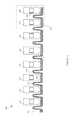
- FIG. 1 is a perspective view of an exemplary annular wearable electronic device that incorporates two elastic electrical cables as adaptive couplers in order to achieve a variable circumference that accommodates a variety of different user forms in accordance with the present systems, articles, and methods.
- FIG. 2 is a plan view of an elastic electrical cable configured to be implemented as an adaptive coupler in an annular wearable electronic device in accordance with the present systems, articles, and methods.
- FIG. 3A is a perspective view of a portion of an elastic electrical cable after the first stage of a multi-stage (or “multi-shot”) overmolding fabrication process in accordance with the present systems, articles, and methods.
- FIG. 3B is a perspective view of a portion of an elastic electrical cable after a second stage of a multi-stage (or “multi-shot”) overmolding fabrication process in accordance with the present systems, articles, and methods.
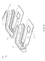
- FIG. 3C is a perspective view of a portion of an elastic electrical cable after a third stage of a multi-stage (or “multi-shot”) overmolding fabrication process in accordance with the present systems, articles, and methods.
- FIG. 4A is a plan view of an elastic electrical cable in an unstretched state in accordance with the present systems, articles, and methods.
- FIG. 4B is a plan view of the elastic electrical cable from FIG. 4A in a stretched state in accordance with the present systems, articles, and methods.
- FIG. 4C is a sectional view of the elastic electrical cable along the line A-A from FIG. 4B .
- FIG. 5 is a flow-diagram showing a method of fabricating an elastic electrical cable in accordance with the present systems, articles, and methods.
- a wearable electronic device that employs one or more such elastic electrical cable(s) to realize a variable circumference that accommodates different user forms.
- at least one elastic electrical cable is used as an “adaptive coupler” that simultaneously provides both electrically conductive coupling and adaptive physical coupling between components of the wearable electronic device.
- the term “elastic electrical cable” generally refers to an electrical cable having elastic properties that render the cable stretchable, expandable, pliable, or otherwise variable in at least one dimension (e.g., length) subject to restorative forces
- the term “adaptive coupler” generally refers to a device or structure that provides flexible, elastic, resilient, adjustable, modifiable, extendable, extensible, or otherwise “adaptive” physical coupling between at least two points/objects.
- Adaptive physical coupling is physical coupling between at least two points/objects that permits limited motion of the two points/objects relative to one another.
- the present systems, articles, and methods describe (among other things) wearable electronic devices that employ elastic electrical cables as adaptive couplers in order to simultaneously provide electrically conductive coupling and adaptive physical coupling between two points/objects of the wearable electronic device through a single coupling structure.
- the term “form” as in “user form” is used to generally describe the physical properties of the portion of a user upon which a wearable electronic device is worn.
- the physical properties may include any characteristic that can influence the fit and/or operation/performance of the wearable electronic device, including but not limited to: shape, size, geometry, topography, mass, volume, density, composition, elasticity, etc.
- FIG. 1 is a perspective view of an exemplary annular wearable electronic device 100 that incorporates two adaptive couplers 111 and 112 in order to achieve a variable circumference that accommodates a variety of different user forms in accordance with the present systems, articles, and methods.
- Exemplary annular wearable electronic device 100 may, for example, form part of a human-electronics interface.
- Exemplary annular wearable electronic device 100 is an armband designed to be worn on the forearm of a user, though a person of skill in the art will appreciate that the teachings described herein may readily be applied in wearable electronic devices (annular or otherwise) designed to be worn elsewhere on the body of the user, including without limitation: on the upper arm, wrist, hand, finger, leg, foot, torso, or neck of the user.
- circumference is used in an approximate sense to generally describe an enclosing boundary (e.g., perimeter) of a curved geometric figure, for example a circle, annulus, or an oval, but is in no way intended to limit the figure being described to a precisely circular geometry.
- annulus is used in an approximate sense to generally describe a curved geometric figure with mass distributed around its circumference and an opening through its volume.
- Device 100 includes a set of eight pod structures 101 , 102 , 103 , 104 , 105 , 106 , 107 , and 108 that form physically coupled links of the wearable electronic device 100 .
- Each pod structure in the set of eight pod structures 101 , 102 , 103 , 104 , 105 , 106 , 107 , and 108 is positioned adjacent at least one other pod structure in the set of pod structures at least approximately on the circumference of the annular wearable electronic device 100 .
- each pod structure in the set of eight pod structures 101 , 102 , 103 , 104 , 105 , 106 , 107 , and 108 is positioned adjacent and in between two other pod structures in the set of eight pod structures such that the set of pod structures forms a circumference or perimeter of an annular or closed loop (e.g., closed surface) configuration.
- pod structure 101 is positioned adjacent and in between pod structures 102 and 108 at least approximately on a circumference or perimeter of the annular or closed loop configuration of pod structures
- pod structure 102 is positioned adjacent and in between pod structures 101 and 103 at least approximately on the circumference or perimeter of the annular or closed loop configuration
- pod structure 103 is positioned adjacent and in between pod structures 102 and 104 at least approximately on the circumference or perimeter of the annular or closed loop configuration, and so on.
- Each of pod structures 101 , 102 , 103 , 104 , 105 , 106 , 107 , and 108 is adaptively physically coupled to the two adjacent pod structures by two adaptive couplers 111 and 112 .
- pod structure 101 is adaptively physically coupled to both pod structure 108 and pod structure 102 by adaptive couplers 111 and 112 .
- the set of eight pod structures may be physically bound in the annular or closed loop configuration by one or more extended adaptive coupler(s) 111 and/or 112 that couple(s) over, across, or through all pod structures in series or by multiple individual adaptive couplers that couple between adjacent pairs of pod structures or between groups of adjacent pairs of pod structures.
- Device 100 is depicted in FIG.
- pod structure is used to refer to an individual link, segment, pod, section, structure, component, etc. of a wearable electronic device.
- an “individual link, segment, pod, section, structure, component, etc.” i.e., a “pod structure”
- pod structures 101 and 102 of device 100 can each be moved or displaced relative to one another within the constraints imposed by the adaptive couplers 111 , 112 providing adaptive physical coupling therebetween.
- the desire for pod structures 101 and 102 to be movable/displaceable relative to one another specifically arises because device 100 is a wearable electronic device that advantageously accommodates the movements of a user and/or different user forms.
- Device 100 includes eight pod structures 101 , 102 , 103 , 104 , 105 , 106 , 107 , and 108 that form physically coupled links thereof.
- the number of pod structures included in a wearable electronic device is dependent on at least the nature, function(s), and design of the wearable electronic device, and the present systems, articles, and methods may be applied to any wearable electronic device employing any number of pod structures, including wearable electronic devices employing more than eight pod structures and wearable electronic devices employing fewer than eight pod structures (e.g., at least two pod structures, such as three or more pod structures).
- pod structures e.g., device 100
- present systems, articles, and methods may be applied to wearable electronic devices that do not employ pod structures (or that employ any number of pod structures).
- pod structures e.g., functions and/or components of pod structures
- wearable electronic device designs should be interpreted as being applicable to any wearable electronic device design, even wearable electronic device designs that do not employ pod structures (except in cases where a pod structure is specifically recited in a claim).
- each of pod structures 101 , 102 , 103 , 104 , 105 , 106 , 107 , and 108 comprises a respective housing having a respective inner volume.
- Each housing may be formed of substantially rigid material and may be optically opaque.
- the term “rigid” as in, for example, “substantially rigid material,” is used to describe a material that has an inherent resiliency, i.e., a tendency to maintain or restore its shape and resist malformation/deformation under the moderate stresses and strains typically encountered by a wearable electronic device.
- FIG. 1 Details of the components contained within the housings (i.e., within the inner volumes of the housings) of pod structures 101 , 102 , 103 , 104 , 105 , 106 , 107 , and 108 are not visible in FIG. 1 .
- some internal components are depicted by dashed lines in FIG. 1 to indicate that these components are contained in the inner volume(s) of housings and may not normally be actually visible in the view depicted in FIG. 1 , unless a transparent or translucent material is employed to form the housings.
- any or all of pod structures 101 , 102 , 103 , 104 , 105 , 106 , 107 , and/or 108 may include electric circuitry (i.e., electrical and/or electronic circuitry).
- a first pod structure 101 is shown containing electric circuitry 121 (i.e., electric circuitry 121 is contained in the inner volume of the housing of pod structure 101 )
- a second pod structure 102 is shown containing electric circuitry 122
- a third pod structure 108 is shown containing electric circuitry 128 .
- the electric circuitry in any or all pod structures may be communicatively coupled to the electric circuitry in at least one other pod structure by at least one communicative pathway (e.g., by at least one electrically conductive pathway and/or by at least one optical pathway).
- communicative pathways may be carried by, carried on, or carried within one or more adaptive couplers.
- adaptive coupler 111 of device 100 is an elastic electrical cable comprising an elastomer band that contains (i.e., enclosed within an inner volume thereof) electrically conductive pathways that provide communicative coupling between various ones of pod structures 101 , 102 , 103 , 104 , 105 , 106 , 107 , and/or 108 .
- Communicative coupling between electric circuitries of pod structures in device 100 may advantageously include systems, articles, and methods for stretchable printed circuit boards as described in U.S. Provisional Patent Application Ser. No. 61/872,569 (now U.S. Non-Provisional patent application Ser. No. 14/471,982) and/or systems, articles, and methods for signal routing as described in U.S. Provisional Patent Application Ser. No. 61/866,960 (now U.S. Non-Provisional patent application Ser. No. 14/461,044), both of which are incorporated by reference herein in their entirety.
- communicative as in “communicative pathway,” “communicative coupling,” and in variants such as “communicatively coupled,” is generally used to refer to any engineered arrangement for transferring and/or exchanging information.
- exemplary communicative pathways include, but are not limited to, electrically conductive pathways (e.g., electrically conductive wires, electrically conductive traces), magnetic pathways (e.g., magnetic media), and/or optical pathways (e.g., optical fiber), and exemplary communicative couplings include, but are not limited to, electrical couplings, magnetic couplings, and/or optical couplings.
- each individual pod structure within a wearable electronic device may perform a particular function, or particular functions.
- each of pod structures 101 , 102 , 103 , 104 , 105 , 106 , and 107 includes a respective sensor 130 (only one called out in FIG. 1 to reduce clutter) responsive to (i.e., to detect) input signals from a user.
- sensor 130 provides electrical signals.
- each of pod structures 101 , 102 , 103 , 104 , 105 , 106 , and 107 includes a respective sensor 130 , each may be referred to as a respective “sensor pod.”
- sensor pod is used to denote an individual pod structure that includes at least one sensor responsive to (i.e., to detect) inputs from a user.
- Each of sensors 130 may be any type of sensor that is capable of detecting a signal produced, generated, or otherwise effected by and/or within the arm of the user, including but not limited to: an electromyography sensor, a magnetomyography sensor, a mechanomyography sensor, a microphone, a blood pressure sensor, a heart rate sensor, a gyroscope, an accelerometer, and/or a thermometer.
- each of sensors 130 includes a respective electromyography (“EMG”) sensor responsive to (i.e., to detect) input signals from the user in the form of electrical signals produced by muscle activity.
- EMG electromyography
- Wearable electronic device 100 may transmit information based on the detected input signals to provide a human-electronics interface (e.g., a human-computer interface). Further details of exemplary electromyography device 100 are described in at least U.S. Non-Provisional patent application Ser. No. 14/186,889, U.S. Non-Provisional patent application Ser. No. 14/194,252, U.S. Provisional Patent Application Ser. No. 61/869,526 (now U.S. Non-Provisional patent application Ser. No. 14/465,194), U.S. Provisional Patent Application Ser. No. 61/909,786 (now U.S. Non-Provisional patent application Ser. No. 14/553,657), and U.S.
- adaptive couplers in annular wearable electronic devices allows the circumference of the device ( 100 ) to vary (i.e., expand and contract) in at least one dimension (e.g., in magnitude) in order to accommodate (i.e., to fit) the form of the part of the user (e.g., forearm or leg) upon which the device is worn.
- This feature is very useful in implementing a “one size fits all” design for a wearable electronic device, and is further advantageous in wearable electronic devices employing sensors (e.g., 130 ) because the even/uniform expansion/contraction afforded by the adaptive couplers can maintain an approximately constant angular spacing between sensors located in different pod structures. Further details of adaptive coupling in wearable electronic devices employing sensors are described in, for example, U.S. Non-Provisional patent application Ser. No. 14/276,575, which is incorporated herein by reference in its entirety.
- Pod structure 108 of device 100 includes a processor 140 that processes the signals provided by the EMG sensors 130 of sensor pods 101 , 102 , 103 , 104 , 105 , 106 , and 107 in response to detected muscle activity.
- Pod structure 108 may therefore be referred to as a “processor pod.”
- processor pod is used to denote an individual pod structure that includes at least one processor to process signals.
- the processor may be any type of processor, including but not limited to: a digital microprocessor or microcontroller, an application-specific integrated circuit (ASIC), a field-programmable gate array (FPGA), a digital signal processor (DSP), a graphics processing unit (GPU), a programmable gate array (PGA), a programmable logic unit (PLU), or the like, that analyzes or otherwise processes the signals to determine at least one output, action, or function based on the signals.
- ASIC application-specific integrated circuit
- FPGA field-programmable gate array
- DSP digital signal processor
- GPU graphics processing unit
- PGA programmable gate array
- PLU programmable logic unit
- Implementations that employ a digital processor may advantageously include a non-transitory processor-readable storage medium or memory 150 communicatively coupled thereto and storing processor-executable instructions that control the operations thereof, whereas implementations that employ an ASIC, FPGA, or analog processor may or may not include a non-transitory processor-readable storage medium 150 .
- processor pod includes an EMG sensor 130 (not visible in FIG.
- processor pod 108 responsive to (i.e., to sense, measure, transduce or otherwise detect) muscle activity of a user, so processor pod 108 could be referred to as a sensor pod.
- processor pod 108 is the only pod structure that includes a processor 140 , thus processor pod 108 is the only pod structure in exemplary device 100 that can be referred to as a processor pod.
- the processor 140 in processor pod 108 also processes the EMG signals provided by the EMG sensor 130 of processor pod 108 .
- multiple pod structures may include processors, and thus multiple pod structures may serve as processor pods.
- some pod structures may not include sensors, and/or some sensors and/or processors may be laid out in other configurations that do not involve pod structures.
- processor 140 includes and/or is communicatively coupled to a non-transitory processor-readable storage medium or memory 150 .
- Memory 150 may store processor-executable gesture identification instructions that, when executed by processor 140 , cause processor 140 to process the EMG signals from EMG sensors 130 and identify a gesture to which the EMG signals correspond.
- wearable electronic device 100 includes at least one communication terminal.
- the term “communication terminal” is generally used to refer to any physical structure that provides a telecommunications link through which a data signal may enter and/or leave a device.
- a communication terminal represents the end (or “terminus”) of communicative signal transfer within a device and the beginning of communicative signal transfer to/from an external device (or external devices).
- device 100 includes a first communication terminal 161 and a second communication terminal 162 .
- First communication terminal 161 includes a wireless transmitter (i.e., a wireless communication terminal) and second communication terminal 162 includes a tethered connector port 162 .
- Wireless transmitter 161 may include, for example, a Bluetooth® transmitter (or similar) and connector port 162 may include a Universal Serial Bus port, a mini-Universal Serial Bus port, a micro-Universal Serial Bus port, a SMA port, a THUNDERBOLT® port, or the like.
- connector port 162 may provide an electrical terminal for charging one or more batteries 170 in device 100 .
- device 100 may also include at least one inertial sensor 180 (e.g., an inertial measurement unit, or “IMU,” that includes at least one accelerometer and/or at least one gyroscope) responsive to (i.e., to detect, sense, or measure) motion effected by a user and which provides signals in response to the detected motion.
- IMU inertial measurement unit
- Signals provided by inertial sensor 180 may be combined or otherwise processed in conjunction with signals provided by EMG sensors 130 .
- a surface EMG sensor may include at least one electrode that resistively or capacitively couples to electrical signals from muscle activity.
- an inertial sensor may include components (e.g., piezoelectric, piezoresistive, capacitive, etc.) that are used to convert physical motion into electrical signals.
- the inertial sensor may “provide” an electrical signal by detecting motion and generating an electrical signal in response to the motion.
- each of pod structures 101 , 102 , 103 , 104 , 105 , 106 , 107 , and 108 may include electric circuitry (i.e., electrical and/or electronic circuitry).
- FIG. 1 depicts electric circuitry 121 inside the inner volume of sensor pod 101 , electric circuitry 122 inside the inner volume of sensor pod 102 , and electric circuitry 128 inside the inner volume of processor pod 118 .
- the circuitry in any or all of pod structures 101 , 102 , 103 , 104 , 105 , 106 , 107 and 108 may include any or all of: an amplification circuit to amplify electrical signals provided by at least one EMG sensor 130 , a filtering circuit to remove unwanted signal frequencies from the signals provided by at least one EMG sensor 130 , and/or an analog-to-digital conversion circuit to convert analog signals into digital signals.
- Device 100 employs a set of communicative pathways (e.g., 191 and 192 ) to route the signals that are output by sensor pods 101 , 102 , 103 , 104 , 105 , 106 , and 107 to processor pod 108 .
- a set of communicative pathways e.g., 191 and 192
- Each respective pod structure 101 , 102 , 103 , 104 , 105 , 106 , 107 , and 108 in device 100 is communicatively coupled to at least processor pod 108 of device 100 .
- the signal(s) from any given sensor pod may be routed through one or more intervening sensor pod(s) (e.g., 101 ) en route to processor pod 108
- other implementations may employ a bus-like architecture in which the signal(s) from each sensor pod 101 , 102 , 103 , 104 , 105 , 106 and 107 are routed directly to processor pod 108 without passing through intervening pod structures.
- each communicative pathway e.g., 191 and 192 , only two illustrated and called out in FIG.
- communicative pathway 191 comprises at least one flexible electrically conductive pathway that extends through a first portion of the inner volume of adaptive coupler 111 and electrically conductively couples to both electric circuitry 128 in processor pod 108 and electric circuitry 121 in sensor pod 101
- communicative pathway 192 comprises at least one electrically conductive pathway that extends through a second portion of the inner volume of adaptive coupler 111 and electrically conductively couples to both electric circuitry 128 in processor pod 108 (either directly, or through communicative pathway 191 , or through one or more other communicative pathways) and electric circuitry 122 in sensor pod 102 .
- Device 100 from FIG. 1 represents an example of a wearable electronic device that employs an elastic electrical cable as an adaptive coupler in accordance with the present systems, articles, and methods.
- an elastic electrical cable is used as adaptive coupler 111 to simultaneously provide both electrically conductive coupling and adaptive physical coupling between pod structures in the set of eight pod structures 101 , 102 , 103 , 104 , 105 , 106 , 107 , and 108 .
- adaptive coupler 111 comprises an elastic electrical cable having at least one electrically conductive pathway (e.g., 191 , 192 ) that is electrically conductively coupled to the respective electric circuitries of at least two pod structures in the set of pod structures 101 , 102 , 103 , 104 , 105 , 106 , 107 , and 108 , where at least a portion of the at least one electrically conductive pathway extends through (e.g., is contained within) an inner volume of an elastomer band 195 .
- at least one electrically conductive pathway e.g., 191 , 192
- adaptive coupler 111 includes electrically conductive pathway 192 that is electrically conductively coupled to the circuitry 121 of a first pod structure 101 and the circuitry 128 of a second pod structure 108 .
- the at least one electrically conductive pathway 192 extends through (e.g., is contained within) an inner volume of an elastomer band 195 , where the band 195 is also physically coupled to both the first pod structure 101 and the second pod structure 108 . Since both the first pod structure 101 and the second pod structure 108 are positioned at least approximately on the circumference of device 100 , the first pod structure 101 and the second pod structure 108 are physically separated from one another by a first distance at least approximately along the circumference of device 100 .
- the portion of elastomer band 195 that couples in between first pod structure 101 and second pod structure 108 has a length that is greater than this first distance (i.e., greater than the distance along the circumference of device 100 that physically separates first pod structure 101 and second pod structure 108 ). This is because the length of elastomer band 195 that couples in between first pod structure 101 and second pod structure 108 includes at least one semi-rigidly set change in direction.
- the semi-rigidly set change in direction for example, takes the form of a bend, turn, twist, curve, corner, step, or offset 199 .
- an annular wearable electronic device may employ multiple individual adaptive couplers each providing adaptive physical coupling between a respective set (e.g., between a respective pair) of pod structures, or an annular wearable device may employ one or more adaptive couplers that provide serial adaptive physical coupling between multiple sets (e.g., between multiple pairs) of pod structures.
- Device 100 employs two adaptive couplers 111 and 112 that each provide serial adaptive physical coupling between all pod structures 101 , 102 , 103 , 104 , 105 , 106 , 107 , and 108 in device 100 .
- Each of adaptive couplers 111 and 112 is positioned at least approximately on the circumference of device 100 and extends completely around the circumference of device 100 .
- adaptive couplers 111 and 112 ensures that, when not worn by a user, the circumference of annular wearable electronic device 100 is a relatively low value with adaptive couplers 111 and 112 each in a respective unstretched, relaxed, contracted, or default state.
- the circumference of annular wearable electronic device 100 may be extended to encircle the portion of the user upon which device 100 is worn (e.g., the forearm) with adaptive couplers 111 and 112 each in a respective stretched or expanded state.
- each of adaptive couplers 111 and 112 is achieved by changing (i.e., reducing or increasing depending on the configuration) an angle of at least one of the semi-rigidly set changes in direction in the length of the corresponding band.
- the stretched or expanded state of adaptive coupler 111 is achieved by reducing the angle (see FIG. 2 ) of the at least one semi-rigidly set change in direction 199 in at least one portion of band 195 that couples in between two adjacent ones of pod structures 101 , 102 , 103 , 104 , 105 , 106 , 107 , and 108 .
- adaptive coupler 111 may advantageously stretch or expand by reducing the angle of the at least one semi-rigidly set change in direction 199 in each portion of band 195 that couples in between two adjacent ones of pod structures 101 , 102 , 103 , 104 , 105 , 106 , 107 , and 108 .
- both of adaptive couplers 111 and 112 may include internal electrically conductive pathways (e.g., 191 , 192 ) that electrically conductively couple to various ones of pod structures 101 , 102 , 103 , 104 , 105 , 106 , 107 , and 108 , or only one of adaptive couplers 111 and 112 may include internal electrically conductive pathways.
- internal electrically conductive pathways e.g., 191 , 192
- only adaptive coupler 111 includes internal electrically conductive pathways and provides electrically communicative coupling between various ones of pod structures 101 , 102 , 103 , 104 , 105 , 106 , 107 , and 108 while adaptive coupler 112 provides only adaptive physical coupling between pod structures 101 , 102 , 103 , 104 , 105 , 106 , 107 , and 108 .
- adaptive coupler 111 is an elastic electrical cable while adaptive coupler 112 is, optionally, not.
- FIG. 2 provides more detail of an elastic electrical cable implemented as an adaptive coupler in a wearable electronic device, such as adaptive coupler 111 of device 100 .
- FIG. 2 is a plan view of an elastic electrical cable 200 configured to be implemented as an adaptive coupler in an annular wearable electronic device in accordance with the present systems, articles, and methods.
- elastic electrical cable 200 may be used as adaptive coupler 111 in device 100 from FIG. 1 .
- Cable 200 comprises a band 201 formed of a molded elastomer (i.e., an elastomer band, analogous to band 195 of adaptive coupler 111 from FIG. 1 ), where the length of the band 201 follows a tortuous path including a number of changes in direction that are semi-rigidly set into the molded elastomer.
- the term “set” as in “semi-rigidly set” is used to indicate that a feature is shaped, molded, or otherwise deliberately formed.
- the semi-rigid changes in direction may be set by the molding process by which elastomer band 201 is formed.
- the term “semi-rigid,” and variants such as “semi-rigidly,” are used to describe a shape or configuration of a material that allows limited deformation under moderate stresses and strains but exhibits a restoring force that effects an inherent resiliency, i.e., a tendency to return to its original shape or configuration when the stresses or strains are removed.
- a sponge has a semi-rigid shape because it will deform when squeezed but will return to its original shape when the squeezing is stopped.
- a “change in direction” is often described as being “semi-rigid” and/or “semi-rigidly set” into a length of an elastomer band.
- a “semi-rigid change in direction” (such as a semi-rigidly set change in direction) is a turn, twist, bend, step, curve, corner, or offset that has a fixed angle in the absence of stresses or strains or other applied forces, allows limited deformation of the angle (i.e., increases and/or decreases in the angle) in response to moderate applied stresses and strains, and has an inherent tendency to return back to the original angle when the applied stresses or strains are removed.
- Semi-rigid changes in direction may be “set” into a path or length of a band material through the process by which the path or length of band material is formed and/or shaped.
- a “semi-rigid change in direction” may be “set” into a length of an elastomer band through a molding process by which the band is formed and shaped.
- Band 201 of FIG. 2 includes a number (specifically, twenty-four in the illustrated example) of semi-rigidly set changes in direction 210 (only one called out in FIG. 2 to reduce clutter), each of which has a respective angle ⁇ (only one called out in FIG. 2 to reduce clutter) that increases/decreases in size when, for example, the two portions of band 201 on either side of the location of the change in direction are pushed together or pulled apart. Because the changes in direction 210 in band 201 are semi-rigidly set, they render band 201 “elastic” or resilient by imparting restoring forces to the angles ⁇ when the two portions of band 201 on either side of the location of each change in direction are pushed together or pulled apart.
- a change in direction may be characterized by an angle in different ways.
- An example angle ⁇ is shown in FIG. 2 which characterizes a change in direction 210 from the point of view of one travelling along the path of band 201 .
- a car travelling along band 201 would have to rotate itself by ⁇ in order to accomplish the corresponding change in direction 210 .
- ⁇ defined this way, the angle of the change in direction 210 will decrease when two portions of band 201 on either side of the change in direction 210 are pulled apart (i.e., band 201 is stretched) and increase when those same two portions of band 201 are pushed together (i.e., band 201 is compressed).
- ⁇ is arbitrary.
- tortuous path is used to generally describe a length that connects between two points and includes a number of changes in direction instead of a direct or straight line.
- a tortuous path may be described as meandering, winding, circuitous, or convoluted and may include changes in direction that result in a serpentine, crenulated, crenelated, boustrophedonic, “zig-zag,” or “back-and-forth” pattern.
- Such changes in direction may include corners or sharp angles (e.g., right-angles), curves, bends, steps, twists, turns, coils, offsets, or any combination thereof.
- such changes in direction are planar (i.e., in the same plane) such that the entire length of cable 200 lies, at least approximately and while cable 200 is not bent into, for example, an annular configuration to serve as an adaptive coupler in an annular wearable electronic device, in a single plane.
- the length of band 201 includes an inner volume that is devoid of elastomer material. As described in more detail later on, this inner volume may be established through the process by which band 201 is formed and/or shaped, such as through a molding process.
- at least a portion of the inner volume of band 201 contains at least a portion of at least one flexible electrically conductive pathway.
- the at least one flexible electrically conductive pathway may comprise an electrically conductive trace carried on a flexible substrate.
- the at least one electrically conductive pathway may be part of a flexible printed circuit board 220 .
- Exemplary elastic electrical cable 200 is specifically configured for use as adaptive coupler 111 in annular wearable electronic device 100 of FIG. 1 .
- the flexible printed circuit board 220 that extends through the inner volume of band 201 includes several portions or ends 221 , 222 , 223 , 224 , 225 , 226 , 227 , and 228 that extend or protrude out of the inner volume of band 201 at various locations.
- Each of the eight portions or ends 221 , 222 , 223 , 224 , 225 , 226 , 227 , and 228 of flexible printed circuit board 220 that extends out of the inner volume of band 201 corresponds to a respective pod structure 101 , 102 , 103 , 104 , 105 , 106 , 107 , and 108 of device 100 and provides electrically conductive coupling to the electric circuitry (e.g., 121 , 122 , 128 ) therein.
- each of the eight portions or ends 221 , 222 , 223 , 224 , 225 , 226 , 227 , and 228 of flexible printed circuit board 220 that extends out of the inner volume of band 201 includes, either carried directly on flexible printed circuit board 220 or carried on a rigid printed circuit board that is coupled to flexible printed circuit board 220 , at least a portion of the electric circuitry (generally represented by circuit component 230 , with only one called out in FIG. 2 to reduce clutter) of a corresponding pod structure 101 , 102 , 103 , 104 , 105 , 106 , 107 , and 108 of device 100 .
- an elastic electrical cable may, in accordance with the present systems, articles, and methods, include any number of portions or ends of flexible electrically conductive pathways that extend out of the inner volume of the band for the purpose of providing electrically conductive couplings to devices or components of devices.
- Each of the eight portions or ends 221 , 222 , 223 , 224 , 225 , 226 , 227 , and 228 of flexible printed circuit board 220 that extends out of the inner volume of band 201 does so at an at least approximately right-angle to the length of cable 200 .
- This feature (among other features) renders cable 200 particularly well-suited for use in applications (such as circumferential adaptive coupler 111 in annular wearable electronic device 100 ) where stretching forces are expected along the length of cable 200 .
- cable 200 (and particularly, elastomer band 201 of cable 200 ) may be formed and shaped by a molding process.
- elastic electrical cables (such as cable 200 ) may be formed by a multi-stage (or “multi-shot”) overmolding process in which: i) a first longitudinal section or portion of the elastomer band 201 is molded by a first molding stage or “shot,” the first longitudinal section having a recessed surface; ii) at least one flexible electrically conductive pathway (e.g., flexible printed circuit board 220 ) is deposited against the recessed surface of the first longitudinal section or portion; and iii) a second longitudinal section or portion of the elastomer band 201 is overmolded by a second molding stage or “shot” to define an “overmold portion” over the flexible electrically conductive pathway and at least a portion of the first longitudinal section of the elastomer band 201 .
- multi-shot multi-stage
- FIGS. 3A, 3B, and 3C each provides an illustrative example of cable 200 from FIG. 2 at a respective one of these three fabrication stages.
- FIG. 3A is a perspective view of a portion 300 a of an elastic electrical cable (e.g., cable 200 from FIG. 2 ) after the first stage of a multi-stage (or “multi-shot”) overmolding fabrication process in accordance with the present systems, articles, and methods.
- Portion 300 a comprises a first longitudinal section 301 a of an elastomer band molded to include a recessed surface 361 and a number of semi-rigid (i.e., semi-rigidly set) changes in direction 310 (only one called out in FIG. 3A to reduce clutter).
- Each semi-rigid change in direction is characterized by a respective angle ⁇ (again, only one called out in FIG.
- stresses and strains e.g., when the ends of first longitudinal section 301 a are pushed together or pulled apart
- substantially the same magnitude i.e., the illustrated magnitude
- first longitudinal section 301 a may be formed of an elastomer material (such as any of a variety of thermoplastic elastomers available from Dupont) and formed using a first mold (i.e., a first molding tool).
- elastomer material such as any of a variety of thermoplastic elastomers available from Dupont
- first mold i.e., a first molding tool
- FIG. 3B is a perspective view of a portion 300 b of an elastic electrical cable (e.g., cable 200 from FIG. 2 ) after a second stage of a multi-stage (or “multi-shot”) overmolding fabrication process in accordance with the present systems, articles, and methods.
- Portion 300 b comprises the first longitudinal section 301 a of an elastomer band from FIG. 3A and a flexible printed circuit board 320 deposited onto/against the recessed surface ( 361 from FIG. 3A , not visible in FIG. 3B due to the placement of flexible printed circuit board 320 thereon) of first longitudinal section 301 a .
- Flexible printed circuit board 320 may be adhered to recessed surface 361 using an adhesive, such as a pressure sensitive adhesive.
- flexible printed circuit board 320 includes a number of portions 321 , 322 that protrude out from and at substantially right angles to first longitudinal section 301 a .
- Each such portion 321 , 322 carries and/or electrically couples to electric circuitry (including discrete electrical components such as 330 ; only one called out in FIG. 3B to reduce clutter) which may be encapsulated in a pod structure (e.g., pod structures 101 , 102 , 103 , 104 , 105 , 106 , 107 , and/or 108 ) of a wearable electronic device (e.g., device 100 ).
- Flexible printed circuit board 320 may carry any number of electrically conductive traces 340 which may route to/from or by-pass any or all of portions 321 , 322 depending on the specific implementation.
- FIG. 3C is a perspective view of a portion 300 c of an elastic electrical cable (e.g., cable 200 from FIG. 2 ) after a third stage of a multi-stage (or “multi-shot”) overmolding fabrication process in accordance with the present systems, articles, and methods.
- Portion 300 c comprises the first longitudinal section 301 a of elastomer from FIG. 3A with the flexible printed circuit board ( 320 from FIG. 3B , not visible in FIG. 3C ) deposited onto/against the recessed surface ( 361 from FIG. 3A , not visible in FIG.
- portion 300 c further comprises a second longitudinal section 301 b of elastomer overmolded over at least a portion of the flexible printed circuit board ( 320 ) and the recessed surface ( 361 ) of first longitudinal section 301 a to enclose the at least a portion of the flexible printed circuit board ( 320 ) within an inner volume of elastomer.
- Portions 321 , 322 of the flexible printed circuit board ( 320 ) protrude from the inner volume of elastomer and may subsequently be encapsulated by pod structures (e.g., 101 , 102 , 103 , 104 , 105 , 106 , 107 , and/or 108 ) of a wearable electronic device (e.g., 100 ).
- pod structures e.g., 101 , 102 , 103 , 104 , 105 , 106 , 107 , and/or 108
- second longitudinal section 301 b of elastomer is molded to include the same semi-rigid (i.e., semi-rigidly set) changes in direction 310 (only one called out in FIG. 3C to reduce clutter) as first longitudinal section 301 a , with each change in direction 310 characterized by a respective angle ⁇ (only one called out FIG. 3C to reduce clutter) as for first longitudinal section 301 a.
- portion 300 c comprises a first longitudinal section 301 a and a second longitudinal section 301 b (i.e., two longitudinally-divided halves), each of which spans the entire length of portion 300 c (and, in general, the entire length of the elastic electrical cable, such as cable 200 ), and which are mated together to form longitudinal seams 351 , 352 .
- FIG. 3C also shows impressions 370 (only one called out in FIG. 3C to reduce clutter) corresponding to the deliberate locations of gates through which elastomer material is injected into the mold when the second longitudinal section 301 b of the cable is formed.
- the first longitudinal section 301 a of molded elastomer has a recessed surface 361 that is sized and dimensioned to receive flexible printed circuit board 320 .
- the depth of the recessed surface 361 may (as illustrated in FIGS. 3A, 3B, and 3C ) be larger than the thickness of flexible printed circuit board 320 and second longitudinal section 301 b of elastomer may be molded substantially into the recess to overmold flexible printed circuit board 320 and recessed surface 361 and substantially fill the depth of the recess.
- the depth of the recessed surface 361 may be at least approximately equal to the thickness of flexible printed circuit board 320 .
- the second “overmold” longitudinal section 301 b of elastomer is overmolded over at least a portion of the exposed surface of flexible printed circuit board 320 and over at least a portion of the first molded longitudinal section 301 a .
- at least a portion of flexible printed circuit board 320 is enclosed or contained within an inner volume of elastomer, the inner volume being defined by a space in between first longitudinal section 301 a and second longitudinal section 301 b .
- the resulting cable may further include holes or access points out of which portions or ends (e.g., 321 , 322 ) of flexible printed circuit board 320 (or one or more connector(s) coupled thereto) may protrude or be accessible (e.g., ports) in order to provide electrically conductive couplings to other devices or components of devices (e.g., to pod structures in annular wearable electronic device 100 ).
- the process of curing the second “overmold” portion having a hole out of which a portion of an electrically conductive pathway protrudes may shrink the overmold elastomer and result in a tight, substantially hermetic seal around the protruding portion of the electrically conductive pathway.
- the elastic electrical cables described herein e.g., cable 200 from FIG. 2
- the cables are particularly well-suited for this application because in use they may simultaneously provide both electrically conductive coupling and adaptive physical coupling between otherwise physically and electrically separate parts.
- electrically conductive coupling is necessary for the device to function electrically and such adaptive physical coupling enables the device to expand and contract in order to accommodate the movements of a user and/or different user forms.
- the elastic electrical cables described herein may be generalized for use in any system where electrically conductive coupling, adaptive physical coupling, or both are desired.
- FIG. 4A is a plan view of an elastic electrical cable 400 in an unstretched, contracted, or relaxed state in accordance with the present systems, articles, and methods. Similar to cable 200 from FIG. 2 , cable 400 comprises an elastomer band 401 through which at least one flexible electrically conductive pathway (e.g., in the form of a conductive trace carried on or by a flexible printed circuit board) extends (i.e., in an inner volume thereof).
- a flexible electrically conductive pathway e.g., in the form of a conductive trace carried on or by a flexible printed circuit board
- Elastomer band 401 is formed by a multi-stage molding process in which a first longitudinal section of band 401 is molded, the at least one flexible electrically conductive pathway is deposited thereon/therein, and a second “overmold” longitudinal section of band 401 is overmolded over at least a portion of the at least one flexible electrically conductive pathway and over at least a portion of the first longitudinal section of band 401 in order to enclose at least a portion of the at least one flexible electrically conductive pathway within band 401 .
- This process produces at least one longitudinal mating seam (not visible in the plan view of cable 400 in FIG. 4A ).
- a first end of the at least one flexible electrically conductive pathway (not visible in FIG.
- a second end of the at least one electrically conductive pathway (also not visible in FIG. 4A ) is proximate (e.g., extends out of) a second end 412 of band 401 where it is electrically conductively coupled to a second electrical connector 422 .
- First electrical connector 421 and second electrical connector 422 are both depicted as male, pin-type connectors in the example of cable 400 ; however, a person of skill in the art will appreciate that any type of electrical connector, including male and female electrical connectors, may be substituted for first electrical connector 421 and/or for second electrical connector 422 depending on the specific application of cable 400 .
- cable 400 includes a number of semi-rigidly set changes in direction 410 (only one called out in FIG. 4A to reduce clutter) that characterize a tortuous path along the length of cable 400 .
- the number of changes in direction 410 may be semi-rigidly set into the length of cable 400 by the molding process through which cable 400 is formed and shaped.
- the number of changes in direction 410 may be first semi-rigidly set into the first longitudinal section of band 401 during the first stage or “shot” of the multi-stage molding process and then similarly semi-rigidly set into the second longitudinal section of band 401 during the second stage or “shot” (i.e., the overmolding stage) of the multi-stage molding process.
- each semi-rigidly set change in direction 410 is characterized by a first angle ⁇ 1 (only one called out in FIG. 4A to reduce clutter).
- each change in direction 410 in cable 400 is semi-rigidly set (e.g., by a molding process) to embody a respective first angle ⁇ 1 .
- Respective first angles ⁇ 1 may or may not be substantially equal for any or all respective ones of changes in direction 410 .
- each first angle ⁇ 1 means that each change in direction 410 in cable 400 exhibits an inherent restoring force that strives to return the respective angle of each change in direction 410 back to its corresponding first angle ⁇ 1 if and when the angle is changed (due to, for example, an expansion, twist, or contraction of cable 400 ).
- FIG. 4A depicts cable 400 in an unstretched, contracted, or relaxed state in which the angle of each change in direction 410 is its corresponding first angle ⁇ 1 .
- FIG. 4B shows the same cable 400 in a stretched or expanded state in which the angle of each change in direction 410 is a respective second angle ⁇ 2 .
- FIG. 4B is a plan view of elastic electrical cable 400 from FIG. 4A in a stretched, expanded, or tense state in accordance with the present systems, articles, and methods.
- Stretching of cable 400 may be accomplished by, for example, pulling first end 411 and/or second end 412 further apart from one another in the directions indicated by the arrows in FIG. 4B . Such may, for example, result from an increase in a diameter or radius (or an increase in the magnitude of the circumference) of an annular or closed loop structure of which the cable 400 is a part.
- each semi-rigidly set change in direction 410 in cable 400 is characterized by a respective second angle ⁇ 2 (only one called out in FIG.
- stretching cable 400 reduces the magnitude of the respective angle of each change in direction 410 so that ⁇ 2 ⁇ 1 .
- stretching the cable causes the angle(s) of one or more semi-rigidly set change(s) in direction to change and gives rise to one or more restoration force(s) that strive(s) to return the one or more angle(s) to the original value(s).
- the restoration force(s) is/are the source of the elasticity or resiliency of the elastic electrical cables described herein.
- FIG. 4B depicts a simple stretched or expanded state of cable 400 in which the cable is essentially elongated along its longitudinal axis. In other words, FIG. 4B shows only a one-dimensional stretch across a single degree of freedom.
- the elastic electrical cables described herein may accommodate stretches or compressions (i.e., extensions or contractions) in all three spatial dimensions (i.e., first end 411 and second end 412 of cable 400 may be repositioned relative to one another in any or all of the three spatial dimensions) and, furthermore, the elastic electrical cables described herein may accommodate torsions, twists, curls, bends, and other stresses/strains across a wide range of degrees of freedom.
- cable 400 comprises an elastomer band 401 that includes an inner volume through which at least a portion of at least one flexible electrically conductive pathway (e.g., at least one flexible printed circuit board) at least partially extends.
- a sectional view of cable 400 is provided in order to illustrate this inner volume.
- FIG. 4C is a sectional view of elastic electrical cable 400 along the line A-A from FIG. 4B .
- elastomer band 401 comprises a first longitudinal section (or “length”) 401 a and a second longitudinal section (or “length”) 401 b with an inner volume 460 enclosed therebetween.
- the sectional view of FIG. 4C also shows flexible printed circuit board 470 contained within inner volume 460 of band 401 .
- the size of inner volume 460 (specifically, relative to the size of flexible printed circuit board 470 ) is exaggerated in FIG. 4C to enhance visual clarity.
- inner volume 460 may have substantially the same cross sectional area as flexible printed circuit board 470 so that there are little to no gaps present in inner volume 460 when flexible printed circuit board 470 is contained therein.
- the first and second longitudinal sections 401 a , 401 b , respectively, of band 401 are mated together along longitudinal mating seams 451 , 452 . Seams 451 and 452 are depicted on the same side/surface of band 401 in FIG. 4C and on a side/surface of band 401 that is widest.
- this placement of seams 451 and 452 may advantageously mitigate splitting along the seams (e.g., in comparison to a configuration in which seams 451 and 452 are located on symmetrically aligned points on two opposing surfaces of band 401 ); however, in other applications either or both of seams 451 and/or 452 may be architected to form elsewhere on band 401 (e.g., on a different side/surface of band 401 ).
- the inner volume 460 of cable 400 is completely defined within the first longitudinal section 401 a of elastomer.
- the first longitudinal section of an elastomer band may be molded, in accordance with the present systems, articles, and methods, to include a recessed surface that is sized and dimensioned to receive a flexible printed circuit board.
- recessed surface 461 is molded into first longitudinal section 401 a of elastomer to receive flexible printed circuit board 470 .
- a layer of adhesive such as pressure sensitive adhesive (not shown in FIG. 4C ) may be applied to either flexible printed circuit board 470 or recessed surface 461 , or both, to adhere flexible printed circuit board 470 to recessed surface 461 .
- first longitudinal section 401 a is molded and flexible printed circuit board 470 is deposited in place on or against recessed surface 461
- second longitudinal section 401 b is overmolded over both flexible printed circuit board 470 and first longitudinal section 401 a (e.g., over recessed surface 461 of first longitudinal section 401 a ) in order to define inner volume 460 in which flexible printed circuit board 470 is contained.
- the depth D of recessed surface 461 may be greater than the thickness of flexible printed circuit board 470 so that second longitudinal section 401 b of elastomer fills the remaining depth (i.e., over flexible printed circuit board 470 ) of the recess during the overmolding process.
- FIG. 5 is a flow-diagram showing a method 500 of fabricating an elastic electrical cable in accordance with the present systems, articles, and methods.
- the elastic electrical cable comprises a flexible printed circuit board that at least partially extends through an inner volume of an elastomer band as illustrated in the examples of adaptive coupler 111 ( FIG. 1 ), cable 200 ( FIG. 2 ), portion 300 c ( FIG. 3C ), and cable 400 ( FIGS. 4A, 4B, and 4C ).
- Method 500 includes three acts 501 , 502 , and 503 , though those of skill in the art will appreciate that in alternative embodiments certain acts may be omitted and/or additional acts may be added.
- method 500 similarly applies to the fabrication of cable 200 from FIG. 2 , to adaptive coupler 111 from FIG. 1 , to portion 300 c from FIG. 3C , and generally to any elastic electrical cable incorporating the teachings of the present systems, articles, and methods.
- a first longitudinal section ( 401 a ) of the elastomer band ( 401 ) component of the elastic electrical cable ( 400 ) is molded.
- the first longitudinal section ( 401 a ) includes a recessed surface ( 461 ) and a number of semi-rigidly set changes in direction ( 410 ).
- molding the first longitudinal section ( 401 a ) of the elastomer band ( 401 ) includes molding a recessed surface ( 461 ) into the first longitudinal section ( 401 a ) and setting a number of semi-rigid changes in direction ( 410 ) along the first longitudinal section ( 401 a ).
- the flexible printed circuit board ( 470 ) component of the elastic electrical cable ( 400 ) is deposited onto or against the recessed surface ( 461 ) of the first longitudinal section ( 401 a ) of the elastomer band ( 401 ).
- Depositing the flexible printed circuit board ( 470 ) onto or against the recessed surface ( 461 ) may include bending the flexible printed circuit board ( 470 ), by hand or using a mechanical apparatus or jig, to match the number of changes in direction ( 410 ) along the first longitudinal section ( 401 a ) of the elastomer band ( 401 ) and positioning the bent flexible printed circuit board ( 470 ) against the recessed surface ( 461 ) of the first longitudinal section ( 401 a ) of the elastomer band ( 401 ).
- a layer of pressure sensitive adhesive may be deposited on or otherwise applied to either a first surface of the flexible printed circuit board ( 470 ), or to the recessed surface of the first longitudinal section ( 401 a ) of elastomer, or to both, and depositing the flexible printed circuit board ( 470 ) onto or against the recessed surface ( 461 ) of the first longitudinal section ( 401 a ) of the elastomer band ( 401 ) may include pressing the flexible printed circuit board ( 470 ) against the recessed surface ( 461 ) of the first longitudinal section ( 401 a ) of the elastomer band ( 401 ) to activate the pressure sensitive adhesive and adhere the first surface of the flexible printed circuit board ( 470 ) to the recessed surface ( 461 ) of the first longitudinal section ( 401 a ) of the elastomer band ( 401 ).
- either no adhesive or a different form of adhesive may be used, such as a temperature sensitive adhesive or a UV light sensitive adhesive if, for example, the elastomer material used to form the first longitudinal section ( 401 a ) is transparent to UV light.
- one or more mechanical molded feature(s) e.g., tongue and groove, chamfered or beveled edges, tabs, protrusions, and the like
- the flexible printed circuit board ( 470 ) i.e., the exposed surface thereof which is opposite the surface that is positioned against the recessed surface ( 461 ) of the first longitudinal section ( 401 a ) of the elastomer band ( 401 )
- at least a portion of the first longitudinal section ( 401 a ) of the elastomer band ( 401 ) are overmolded with a second longitudinal section ( 401 b ) of the elastomer band ( 401 ).
- Overmolding the flexible printed circuit board ( 470 ) and at least a portion of the first longitudinal section ( 401 a ) of the elastomer band ( 401 ) with a second longitudinal section ( 401 b ) of the elastomer band ( 401 ) encloses at least a portion of the flexible printed circuit board ( 470 ) within the inner volume ( 460 ) of the elastomer band ( 401 ) and may result in one or more longitudinal mating seam(s) ( 451 , 452 ) between the first longitudinal section ( 401 a ) and the second longitudinal section ( 401 b ) of the elastomer band ( 401 ).
- a first portion of a structure is typically molded using (e.g., by injection of a moldable material into) a first portion of a mold and then a second portion of the structure is molded over at least a portion of the first portion of the structure using (e.g., by injection of a moldable material into) a second portion of the mold.
- a first mold for the first longitudinal section of elastomer and a second mold for the second longitudinal section of elastomer i.e., a first mold for the first longitudinal section of elastomer and a second mold for the second longitudinal section of elastomer.
- the first longitudinal section of elastomer may be removed from the first mold and the flexible printed circuit board may be deposited onto/against the recessed surface of the first longitudinal section of elastomer while the first longitudinal section of elastomer is outside of the first mold.
- the first longitudinal section of elastomer may be deposited onto an inner surface of the second mold and the flexible printed circuit board may be deposited onto/against the recessed surface of the first longitudinal section of elastomer while the first longitudinal section of elastomer is on the inner surface of the second mold.
- This configuration allows the flexible printed circuit board to be pressed against the recessed surface of the first longitudinal section of elastomer (either by hand or by a mechanical apparatus such as a jig) and secured in place while the first longitudinal section of elastomer is in the second mold. If a pressure sensitive adhesive layer is used in between the recessed surface of the first longitudinal section of elastomer and the flexible printed circuit board, then this configuration also allows the pressure sensitive adhesive layer to be activated within the second mold.
- a mold In a typical molding process (whether involving overmolding or not), a mold is designed to be some percentage larger than the actual intended size of the structure being molded. This is to accommodate for shrinkage of the molded structure during cooling/curing of the molded material.
- molded elastomer structures typically shrink during the cooling/curing stage of the molding process and the corresponding mold is typically dimensioned to accommodate for this X % shrinkage (i.e., sized a corresponding percentage larger than the intended final size of the molded structure).
- Shrinkage effects are particularly influential in overmolding processes such as those described in the present systems, articles, and methods.
- Unanticipated shrinkage of an overmolding layer i.e., of a molded layer that overmolds one or more other layer(s)
- the present systems, articles, and methods teach ways in which unwanted shrinkage effects in an elastic electrical cable in which one or more elastomer layers overmold a flexible printed circuit board can be mitigated.
- the first mold may be sized and dimensioned to accommodate 0% shrinkage of the first longitudinal section of the elastomer band.
- the first mold may not incorporate any adjustment or tolerance to account for shrinkage of the first longitudinal section of elastomer so that after cooling/curing the first longitudinal section of elastomer shrinks to a size that is in fact smaller than the intended final size of the elastomer band.
- the phrase “sized and dimensioned to accommodate 0% shrinkage” is not intended to mean that 0% shrinkage occurs, but is rather intended to mean that the corresponding mold is not sized and dimensioned to accommodate anything other than 0% shrinkage.
- a mold that is “sized and dimensioned to accommodate 0% shrinkage is deliberately not sized and dimensioned to compensate for any shrinkage that may occur. That is, the corresponding mold is not designed to be any percentage larger than the intended final size of the molded structure despite the fact that some shrinkage of the molded structure may be expected to occur.
- the shrunken first longitudinal section of elastomer may be removed from the first mold and deposited onto an inner surface of the second mold.
- depositing the first longitudinal section of elastomer onto an inner surface of the second mold may advantageously include stretching the first longitudinal section of elastomer onto the inner surface of the second mold.
- the second mold may also be sized and dimensioned to accommodate 0% shrinkage of the second longitudinal section of elastomer and the first longitudinal section of elastomer may be stretched to its intended final size when deposited onto or against the inner surface of the second mold.
- the flexible printed circuit board may be deposited onto/against the recessed surface of the first longitudinal section of elastomer and both the flexible printed circuit board and at least a portion of the first longitudinal section of elastomer may be overmolded with the second longitudinal section of elastomer.
- any shrinkage of the first and/or second longitudinal section(s) of elastomer is limited by the flexible printed circuit board enclosed thereby and may be essentially evenly distributed if the same elastomer material is used for both the first and second longitudinal section. Such shrinkage can advantageously help secure the flexible printed board in place within the inner volume of the overmolded elastomer band.
- a further aspect of method 500 is the locations of the “gates” through which elastomer material is injected into a mold.
- the locations of the gates through which elastomer material is injected into the second mold is particularly influential because when the elastomer material is injected into the second mold it impinges upon a surface of the flexible printed circuit board (which is deposited upon/against the recessed surface of the first longitudinal section of elastomer) and can cause the flexible printed circuit board to slide, bunch, or otherwise become displaced relative to its original and/or intended position against the recessed surface of the first longitudinal section of elastomer.
- a first gate of the second mold may be positioned at (or at least, proximate to) a first one of the number of semi-rigid changes in direction in the first longitudinal section of the elastomer band. See impression 370 in FIG. 3C for an example of this approximate position. From this position, elastomer material injected into the second mold through the gate initially impinges on the flexible printed circuit board at the vertex of the change in direction and then spreads along the two portions of the first longitudinal section that connect to that vertex.
- the flexible printed circuit board As the injected elastomer spreads from the gate, the flexible printed circuit board is pressed against the vertex of the change in direction and then gradually pressed down along the lengths of the two portions of the first longitudinal section that connect at that vertex.
- a layer of pressure sensitive adhesive may be sandwiched in between the flexible printed circuit board and the recessed surface of the first longitudinal section of elastomer, and with the gate in this position the pressure sensitive adhesive may first be activated at the vertex of the change in direction to adhere/secure the flexible printed circuit board in position against the recessed surface of the first longitudinal section of elastomer at that vertex and then gradually activated to adhere/secure the flexible printed circuit board along the lengths of the portions of the first longitudinal section of elastomer that connect at that vertex.
- a plurality of additional gates can be employed in the second mold during injection of the elastomer material forming the second longitudinal section of elastomer, and for each gate in the plurality of additional gates to be positioned at a location of a respective one of the multiple semi-rigid changes in direction.
- elastomer material injected through each respective gate will bind the flexible printed circuit board to the respective vertices of the changes in direction and then spread along the length of the cable structure to meet/merge at the relatively straight portions in the length of the cable where stresses/strains are likely to be minimal during use.
- the restoring forces effected by changing the angle of a semi-rigidly set change in direction in an elastomer band may be gentler, and may grow less dramatically as the change in the angle is increased, compared to other sources of elasticity.
- a straight elastic cable is known (in accordance with Hooke's Law) to exhibit linear elasticity meaning that the restoration force grows linearly as the length of the cable is stretched.
- the tortuous cables described herein can provide sub-linear elasticity so that the restoring force grows sub-linearly as the length of the cable is stretched. This is a further feature that renders the elastic electrical cables described herein particularly well-suited for use in wearable electronic devices.
- a user with a particularly large forearm that causes adaptive couplers 111 and 112 to stretch to a large extent may nevertheless comfortably don device 100 because the tortuous nature of adaptive couplers 111 and 112 provides a sub-linear (or, ideally, near constant within the expected circumference range of device 100 ) restoring force such that device 100 feels “less tight” on the arm of such a user then, for example, a similar configuration that employed straight adaptive couplers with no semi-rigidly set changes in direction.
- a further advantage of the band geometries described herein is that such geometries may provide substantially uniform compressive forces on the limb of the user upon which the band is worn (e.g., on the arm of the user) to enhance comfort and performance of on-board, contact-based sensors such as sensors 130 . Likewise, such geometries may expand substantially uniformly to maintain uniform angular spacing between sensors 130 as described in U.S. Non-Provisional patent application Ser. No. 14/276,575.
- elastomer material, such as an “elastomer band.”
- the term elastomer is used to generally encompass polymers that exhibit viscoelasticity (such as thermosets and/or thermoplastics) but, in principle, elastomers are used only as examples herein and may be substituted by any material that likewise exhibits sufficient elasticity to apply the teachings of the present systems, articles, and methods in any particular application.
- Thermoplastics formulated by Dupont are used as non-limiting examples of elastomer materials in the present systems, articles, and methods. The composition of the elastomer material will influence the physical properties of the resulting molded structure.
- Composite materials may be used (e.g., including materials integrated into an elastomer, such as Kevlar®, textiles, laminate materials and/or filler materials), where the composition of the material may be selected to provide desired properties in the molded structure.
- stiffeners may be added to the elastomer material either uniformly throughout, or at specific locations in the molded shape, to achieve uniform or localized isotropic (or anisotropic) control of the deformation properties of the molded structure.
- geometric features e.g., mechanical flexures
- either the same or different elastomer material(s) may be used at successive stages of a multi-shot overmold process in accordance with the present systems, articles, and methods. That is, in some applications a first shot (e.g., a first longitudinal section 301 a ) may be molded using a first elastomer material and a second shot (e.g., a second longitudinal section 301 b ) may be molded over at least a portion of the first shot using a second elastomer material.
- a first shot e.g., a first longitudinal section 301 a
- a second shot e.g., a second longitudinal section 301 b
- the present systems, articles, and methods generally describe overmolded electric structures, and methods of manufacturing thereof, in which at least one overmolded electrically conductive pathway is a flexible electrically conductive pathway, such as a conductive trace on a flexible printed circuit board.
- at least one overmolded electrically conductive pathway is a flexible electrically conductive pathway, such as a conductive trace on a flexible printed circuit board.
- Such flexibility is generally advantageous in application where a degree of elasticity in the overmolded electric structure is desired, such as in adaptive couplers of wearable electronic devices.
- the methods of manufacturing/fabricating overmolded electric structures described herein may generally be applied using substantially rigid electric structures, for example structures that are not required/desired to be elastic, or more generally in any electric device that includes at least one electrically conductive pathway.
- rigid electronics and/or rigid printed circuit boards may be at least partially contained in the inner volume of an elastomer material by using any or all of the techniques and methods of multi-stage overmolding described herein (except those aspects that are specifically described/claimed as involving flexible elements).
- infinitive verb forms are often used. Examples include, without limitation: “to detect,” “to provide,” “to transmit,” “to communicate,” “to process,” “to route,” and the like. Unless the specific context requires otherwise, such infinitive verb forms are used in an open, inclusive sense, that is as “to, at least, detect,” to, at least, provide,” “to, at least, transmit,” and so on.
- logic or information can be stored on any processor-readable medium for use by or in connection with any processor-related system or method.
- a memory is a processor-readable medium that is an electronic, magnetic, optical, or other physical device or means that contains or stores a computer and/or processor program.
- Logic and/or the information can be embodied in any processor-readable medium for use by or in connection with an instruction execution system, apparatus, or device, such as a processor-based system, processor-containing system, or other system that can fetch the instructions from the instruction execution system, apparatus, or device and execute the instructions associated with logic and/or information.
- a “non-transitory processor-readable medium” can be any element that can store the program associated with logic and/or information for use by or in connection with the instruction execution system, apparatus, and/or device.
- the processor-readable medium can be, for example, but is not limited to, an electronic, magnetic, optical, electromagnetic, infrared, or semiconductor system, apparatus or device.
- processor-readable medium More specific examples (a non-exhaustive list) of the processor-readable medium would include the following: a portable computer diskette (magnetic, compact flash card, secure digital, or the like), a random access memory (RAM), a read-only memory (ROM), an erasable programmable read-only memory (EPROM, EEPROM, or Flash memory), a portable compact disc read-only memory (CDROM), digital tape, and other non-transitory media.
- portable computer diskette magnetic, compact flash card, secure digital, or the like
- RAM random access memory
- ROM read-only memory
- EPROM erasable programmable read-only memory
- Flash memory erasable programmable read-only memory
- CDROM compact disc read-only memory
- digital tape digital tape
Abstract
Description
Claims (28)
Priority Applications (1)
| Application Number | Priority Date | Filing Date | Title |
|---|---|---|---|
| US14/621,044 US9600030B2 (en) | 2014-02-14 | 2015-02-12 | Systems, articles, and methods for elastic electrical cables and wearable electronic devices employing same |
Applications Claiming Priority (3)
| Application Number | Priority Date | Filing Date | Title |
|---|---|---|---|
| US201461940048P | 2014-02-14 | 2014-02-14 | |
| US201462031651P | 2014-07-31 | 2014-07-31 | |
| US14/621,044 US9600030B2 (en) | 2014-02-14 | 2015-02-12 | Systems, articles, and methods for elastic electrical cables and wearable electronic devices employing same |
Publications (2)
| Publication Number | Publication Date |
|---|---|
| US20150234426A1 US20150234426A1 (en) | 2015-08-20 |
| US9600030B2 true US9600030B2 (en) | 2017-03-21 |
Family
ID=53798101
Family Applications (1)
| Application Number | Title | Priority Date | Filing Date |
|---|---|---|---|
| US14/621,044 Active 2035-02-24 US9600030B2 (en) | 2014-02-14 | 2015-02-12 | Systems, articles, and methods for elastic electrical cables and wearable electronic devices employing same |
Country Status (7)
| Country | Link |
|---|---|
| US (1) | US9600030B2 (en) |
| EP (1) | EP3104737A4 (en) |
| JP (1) | JP2017509386A (en) |
| KR (1) | KR102372544B1 (en) |
| CN (1) | CN106102504A (en) |
| CA (1) | CA2939644A1 (en) |
| WO (1) | WO2015123445A1 (en) |
Cited By (48)
| Publication number | Priority date | Publication date | Assignee | Title |
|---|---|---|---|---|
| US20150051470A1 (en) * | 2013-08-16 | 2015-02-19 | Thalmic Labs Inc. | Systems, articles and methods for signal routing in wearable electronic devices |
| US20180000373A1 (en) * | 2015-01-19 | 2018-01-04 | National University Corporation Hokkaido University | Myoelectric sensor |
| US20180024642A1 (en) * | 2016-07-20 | 2018-01-25 | Autodesk, Inc. | No-handed smartwatch interaction techniques |
| US20180095430A1 (en) * | 2016-09-30 | 2018-04-05 | Compal Electronics, Inc. | Wearable device and functional module thereof |
| US20180188694A1 (en) * | 2016-03-28 | 2018-07-05 | Boe Technology Group Co., Ltd. | Wearable article |
| US10101809B2 (en) | 2013-11-12 | 2018-10-16 | Thalmic Labs Inc. | Systems, articles, and methods for capacitive electromyography sensors |
| US10254795B2 (en) * | 2015-05-06 | 2019-04-09 | Flexterra, Inc. | Attachable, flexible display device with flexible tail |
| US10251577B2 (en) | 2013-11-27 | 2019-04-09 | North Inc. | Systems, articles, and methods for electromyography sensors |
| US10409371B2 (en) | 2016-07-25 | 2019-09-10 | Ctrl-Labs Corporation | Methods and apparatus for inferring user intent based on neuromuscular signals |
| US10459495B2 (en) * | 2017-12-19 | 2019-10-29 | North Inc. | Wearable electronic devices having an inward facing input device and methods of use thereof |
| US10460455B2 (en) | 2018-01-25 | 2019-10-29 | Ctrl-Labs Corporation | Real-time processing of handstate representation model estimates |
| US10489986B2 (en) | 2018-01-25 | 2019-11-26 | Ctrl-Labs Corporation | User-controlled tuning of handstate representation model parameters |
| US10496168B2 (en) | 2018-01-25 | 2019-12-03 | Ctrl-Labs Corporation | Calibration techniques for handstate representation modeling using neuromuscular signals |
| US10504286B2 (en) | 2018-01-25 | 2019-12-10 | Ctrl-Labs Corporation | Techniques for anonymizing neuromuscular signal data |
| US10579099B2 (en) * | 2018-04-30 | 2020-03-03 | Apple Inc. | Expandable ring device |
| US10592001B2 (en) | 2018-05-08 | 2020-03-17 | Facebook Technologies, Llc | Systems and methods for improved speech recognition using neuromuscular information |
| US10684692B2 (en) | 2014-06-19 | 2020-06-16 | Facebook Technologies, Llc | Systems, devices, and methods for gesture identification |
| US10687759B2 (en) | 2018-05-29 | 2020-06-23 | Facebook Technologies, Llc | Shielding techniques for noise reduction in surface electromyography signal measurement and related systems and methods |
| US10716912B2 (en) | 2015-03-31 | 2020-07-21 | Fisher & Paykel Healthcare Limited | User interface and system for supplying gases to an airway |
| US10772519B2 (en) | 2018-05-25 | 2020-09-15 | Facebook Technologies, Llc | Methods and apparatus for providing sub-muscular control |
| US10817795B2 (en) | 2018-01-25 | 2020-10-27 | Facebook Technologies, Llc | Handstate reconstruction based on multiple inputs |
| US10842407B2 (en) | 2018-08-31 | 2020-11-24 | Facebook Technologies, Llc | Camera-guided interpretation of neuromuscular signals |
| US10905383B2 (en) | 2019-02-28 | 2021-02-02 | Facebook Technologies, Llc | Methods and apparatus for unsupervised one-shot machine learning for classification of human gestures and estimation of applied forces |
| US10921764B2 (en) | 2018-09-26 | 2021-02-16 | Facebook Technologies, Llc | Neuromuscular control of physical objects in an environment |
| US10937414B2 (en) | 2018-05-08 | 2021-03-02 | Facebook Technologies, Llc | Systems and methods for text input using neuromuscular information |
| US10970936B2 (en) | 2018-10-05 | 2021-04-06 | Facebook Technologies, Llc | Use of neuromuscular signals to provide enhanced interactions with physical objects in an augmented reality environment |
| US10970374B2 (en) | 2018-06-14 | 2021-04-06 | Facebook Technologies, Llc | User identification and authentication with neuromuscular signatures |
| US10990174B2 (en) | 2016-07-25 | 2021-04-27 | Facebook Technologies, Llc | Methods and apparatus for predicting musculo-skeletal position information using wearable autonomous sensors |
| US11000211B2 (en) | 2016-07-25 | 2021-05-11 | Facebook Technologies, Llc | Adaptive system for deriving control signals from measurements of neuromuscular activity |
| US11045137B2 (en) | 2018-07-19 | 2021-06-29 | Facebook Technologies, Llc | Methods and apparatus for improved signal robustness for a wearable neuromuscular recording device |
| US11069148B2 (en) | 2018-01-25 | 2021-07-20 | Facebook Technologies, Llc | Visualization of reconstructed handstate information |
| US11179066B2 (en) | 2018-08-13 | 2021-11-23 | Facebook Technologies, Llc | Real-time spike detection and identification |
| US11216069B2 (en) | 2018-05-08 | 2022-01-04 | Facebook Technologies, Llc | Systems and methods for improved speech recognition using neuromuscular information |
| US11324908B2 (en) | 2016-08-11 | 2022-05-10 | Fisher & Paykel Healthcare Limited | Collapsible conduit, patient interface and headgear connector |
| US11331045B1 (en) | 2018-01-25 | 2022-05-17 | Facebook Technologies, Llc | Systems and methods for mitigating neuromuscular signal artifacts |
| US11337652B2 (en) | 2016-07-25 | 2022-05-24 | Facebook Technologies, Llc | System and method for measuring the movements of articulated rigid bodies |
| US11481031B1 (en) | 2019-04-30 | 2022-10-25 | Meta Platforms Technologies, Llc | Devices, systems, and methods for controlling computing devices via neuromuscular signals of users |
| US11481030B2 (en) | 2019-03-29 | 2022-10-25 | Meta Platforms Technologies, Llc | Methods and apparatus for gesture detection and classification |
| US11484242B2 (en) * | 2016-12-02 | 2022-11-01 | Pison Technology, Inc. | Detecting and using body tissue electrical signals |
| US11493993B2 (en) | 2019-09-04 | 2022-11-08 | Meta Platforms Technologies, Llc | Systems, methods, and interfaces for performing inputs based on neuromuscular control |
| US11567573B2 (en) | 2018-09-20 | 2023-01-31 | Meta Platforms Technologies, Llc | Neuromuscular text entry, writing and drawing in augmented reality systems |
| US11635736B2 (en) | 2017-10-19 | 2023-04-25 | Meta Platforms Technologies, Llc | Systems and methods for identifying biological structures associated with neuromuscular source signals |
| US11644799B2 (en) | 2013-10-04 | 2023-05-09 | Meta Platforms Technologies, Llc | Systems, articles and methods for wearable electronic devices employing contact sensors |
| US11797087B2 (en) | 2018-11-27 | 2023-10-24 | Meta Platforms Technologies, Llc | Methods and apparatus for autocalibration of a wearable electrode sensor system |
| US11868531B1 (en) | 2021-04-08 | 2024-01-09 | Meta Platforms Technologies, Llc | Wearable device providing for thumb-to-finger-based input gestures detected based on neuromuscular signals, and systems and methods of use thereof |
| US11896503B2 (en) | 2018-07-16 | 2024-02-13 | Imperial College Innovations Limited | Methods for enabling movement of objects, and associated apparatus |
| US11907423B2 (en) | 2019-11-25 | 2024-02-20 | Meta Platforms Technologies, Llc | Systems and methods for contextualized interactions with an environment |
| US11921471B2 (en) | 2013-08-16 | 2024-03-05 | Meta Platforms Technologies, Llc | Systems, articles, and methods for wearable devices having secondary power sources in links of a band for providing secondary power in addition to a primary power source |
Families Citing this family (27)
| Publication number | Priority date | Publication date | Assignee | Title |
|---|---|---|---|---|
| US20140198034A1 (en) | 2013-01-14 | 2014-07-17 | Thalmic Labs Inc. | Muscle interface device and method for interacting with content displayed on wearable head mounted displays |
| WO2014186370A1 (en) | 2013-05-13 | 2014-11-20 | Thalmic Labs Inc. | Systems, articles and methods for wearable electronic devices that accommodate different user forms |
| US9788789B2 (en) * | 2013-08-30 | 2017-10-17 | Thalmic Labs Inc. | Systems, articles, and methods for stretchable printed circuit boards |
| US10199008B2 (en) | 2014-03-27 | 2019-02-05 | North Inc. | Systems, devices, and methods for wearable electronic devices as state machines |
| USD756359S1 (en) * | 2014-05-15 | 2016-05-17 | Thalmic Labs Inc. | Expandable armband device |
| US9807221B2 (en) | 2014-11-28 | 2017-10-31 | Thalmic Labs Inc. | Systems, devices, and methods effected in response to establishing and/or terminating a physical communications link |
| USD770322S1 (en) * | 2015-01-13 | 2016-11-01 | Lynn Ban | Jewelry item |
| CN104615206B (en) * | 2015-02-27 | 2018-09-14 | 京东方科技集团股份有限公司 | A kind of Wearable |
| US10078435B2 (en) | 2015-04-24 | 2018-09-18 | Thalmic Labs Inc. | Systems, methods, and computer program products for interacting with electronically displayed presentation materials |
| TWI583292B (en) | 2015-09-03 | 2017-05-11 | 宏碁股份有限公司 | Electronic device and assembly method thereof |
| US10446329B2 (en) | 2015-09-23 | 2019-10-15 | University Of Virginia Patent Foundation | Process of forming electrodes and products thereof from biomass |
| KR102553177B1 (en) | 2016-06-13 | 2023-07-10 | 삼성전자주식회사 | Electronic device comprising high frequency transmitting circuit |
| US10091904B2 (en) * | 2016-07-22 | 2018-10-02 | Intel Corporation | Storage sled for data center |
| WO2018032060A1 (en) * | 2016-08-18 | 2018-02-22 | Durso Paul S | Wearable medical device and systems derived therefrom |
| US10902743B2 (en) | 2017-04-14 | 2021-01-26 | Arizona Board Of Regents On Behalf Of Arizona State University | Gesture recognition and communication |
| US11723581B2 (en) * | 2018-10-23 | 2023-08-15 | Massachusetts Institute Of Technology | Electromyography sensor |
| US11206475B2 (en) * | 2018-12-07 | 2021-12-21 | Starkey Laboratories, Inc. | Wearable electronic device and strap arrangement with charging ports for charging ear-worn electronic devices |
| EP3725256B1 (en) * | 2019-04-16 | 2023-08-30 | Stryker European Operations Limited | Tracker for surgical navigation |
| CN110393341B (en) * | 2019-06-28 | 2021-04-16 | 努比亚技术有限公司 | Chain assembly and wearable equipment |
| CN210809549U (en) * | 2019-08-19 | 2020-06-23 | 北京海益同展信息科技有限公司 | Wearable gesture recognition equipment |
| CN110537758A (en) * | 2019-09-24 | 2019-12-06 | 北京海益同展信息科技有限公司 | Arm ring structure |
| WO2021067704A1 (en) * | 2019-10-02 | 2021-04-08 | Jabil Inc. | Wearable band for biomarker tracking |
| US20210120690A1 (en) * | 2019-10-22 | 2021-04-22 | GE Precision Healthcare LLC | Methods and systems for cable management |
| KR102305316B1 (en) * | 2019-12-27 | 2021-09-27 | 고병지 | Smart devices with active size adjustment |
| KR102283617B1 (en) | 2020-02-10 | 2021-07-28 | 김대중 | Multiple channel Bio signal measurement device |
| DE102020134938A1 (en) * | 2020-12-28 | 2022-06-30 | Motesque, Inc. | Set of a body mount and sensor unit |
| WO2023164211A1 (en) * | 2022-02-25 | 2023-08-31 | Meta Platforms Technologies, Llc | Smart electrodes for sensing signals and processing signals using internally-housed signal-processing components at wearable devices and wearable devices incorporating the smart electrodes |
Citations (178)
| Publication number | Priority date | Publication date | Assignee | Title |
|---|---|---|---|---|
| US1411995A (en) | 1919-06-20 | 1922-04-04 | Raymond W Dull | Link belt |
| US3620208A (en) | 1969-11-03 | 1971-11-16 | Atomic Energy Commission | Ekg amplifying electrode pickup |
| US3880146A (en) | 1973-06-04 | 1975-04-29 | Donald B Everett | Noise compensation techniques for bioelectric potential sensing |
| US4602639A (en) | 1982-07-01 | 1986-07-29 | Mardice Holding S.A.R.L. | Method and apparatus for contactless measurement of charge concentrations and potential differences in biological organisms |
| EP0301790A2 (en) | 1987-07-24 | 1989-02-01 | BioControl Systems, Inc. | Biopotential digital controller for music and video applications |
| US4817064A (en) | 1985-02-05 | 1989-03-28 | Milles Victor A | Structure for fabricating jewelry parts or wrist watches |
| US5003978A (en) | 1985-08-21 | 1991-04-02 | Technology 21, Inc. | Non-polarizable dry biomedical electrode |
| USD322227S (en) | 1989-03-23 | 1991-12-10 | North American Watch Company | Watch |
| US5081852A (en) | 1991-02-14 | 1992-01-21 | Cox Michael F | Display bracelet |
| US5251189A (en) | 1992-10-16 | 1993-10-05 | Timex Corporation | Wristwatch radiotelephone |
| USD348660S (en) | 1993-04-29 | 1994-07-12 | Micro-Integration Corp. | Hand-held computer input device |
| US5445869A (en) | 1993-01-21 | 1995-08-29 | Matsushita Electric Industrial Co., Ltd. | Composite flexible substrate |
| DE4412278A1 (en) | 1994-04-09 | 1995-10-12 | Bosch Gmbh Robert | Circuit board with both rigid and flexible regions |
| US5482051A (en) | 1994-03-10 | 1996-01-09 | The University Of Akron | Electromyographic virtual reality system |
| US5605059A (en) | 1995-03-09 | 1997-02-25 | Woodward; Robin | Sleeved bangle bracelet |
| US5683404A (en) | 1996-06-05 | 1997-11-04 | Metagen, Llc | Clamp and method for its use |
| US6032530A (en) | 1994-04-29 | 2000-03-07 | Advantedge Systems Inc. | Biofeedback system for sensing body motion and flexure |
| US6184847B1 (en) | 1998-09-22 | 2001-02-06 | Vega Vista, Inc. | Intuitive control of portable data displays |
| US6238338B1 (en) | 1999-07-19 | 2001-05-29 | Altec, Inc. | Biosignal monitoring system and method |
| US6244873B1 (en) | 1998-10-16 | 2001-06-12 | At&T Corp. | Wireless myoelectric control apparatus and methods |
| US20020032386A1 (en) | 2000-04-17 | 2002-03-14 | Sackner Marvin A. | Systems and methods for ambulatory monitoring of physiological signs |
| US6377277B1 (en) | 1995-08-10 | 2002-04-23 | Sega Enterprises, Ltd. | Virtual image generation apparatus and method |
| US20020077534A1 (en) | 2000-12-18 | 2002-06-20 | Human Bionics Llc | Method and system for initiating activity based on sensed electrophysiological data |
| USD459352S1 (en) | 2001-08-10 | 2002-06-25 | Michael C. Giovanniello | Wireless mouse wristband |
| US6487906B1 (en) | 2000-09-18 | 2002-12-03 | Advantedge Systems Inc | Flexible film sensor system for monitoring body motion |
| US6510333B1 (en) | 2000-05-16 | 2003-01-21 | Mark J. Licata | Sensor for biopotential measurements |
| US20030036691A1 (en) | 2000-08-10 | 2003-02-20 | Stanaland Thomas G. | Capacitively coupled electrode system with variable capacitance for sensing potentials at the surface of tissue |
| US6527711B1 (en) | 1999-10-18 | 2003-03-04 | Bodymedia, Inc. | Wearable human physiological data sensors and reporting system therefor |
| US20030144586A1 (en) | 2002-01-31 | 2003-07-31 | Keisuke Tsubata | Biological information sensing device |
| US6619836B1 (en) | 1999-11-11 | 2003-09-16 | The Swatch Group Management Services Ag | Electronic wristwatch including a printed circuit incorporated in a flexible wristband |
| US20040068409A1 (en) | 2002-10-07 | 2004-04-08 | Atau Tanaka | Method and apparatus for analysing gestures produced in free space, e.g. for commanding apparatus by gesture recognition |
| US6720984B1 (en) | 2000-06-13 | 2004-04-13 | The United States Of America As Represented By The Administrator Of The National Aeronautics And Space Administration | Characterization of bioelectric potentials |
| US20040073104A1 (en) | 2001-02-23 | 2004-04-15 | Riccardo Brun Del Re | Enhanced pickup-electrode |
| US6743982B2 (en) | 2000-11-29 | 2004-06-01 | Xerox Corporation | Stretchable interconnects using stress gradient films |
| US20040194500A1 (en) | 2003-04-03 | 2004-10-07 | Broadway Entertainment, Inc. | Article of jewelry |
| US6807438B1 (en) | 1999-08-26 | 2004-10-19 | Riccardo Brun Del Re | Electric field sensor |
| US20040210165A1 (en) | 2001-10-26 | 2004-10-21 | George Marmaropoulos | Selectively applied wearable medical sensors |
| US20050005637A1 (en) | 2003-04-03 | 2005-01-13 | Abbie Rapport | Article of jewelry |
| US20050012715A1 (en) | 2003-06-12 | 2005-01-20 | Peter Charles Shann Hubird Ford | Method, system, and software for interactive communication and analysis |
| US6865409B2 (en) | 2001-11-07 | 2005-03-08 | Kinesense, Inc. | Surface electromyographic electrode assembly |
| USD502661S1 (en) | 2004-02-23 | 2005-03-08 | Broadway Entertainment, Inc. | Bracelet |
| USD502662S1 (en) | 2004-02-23 | 2005-03-08 | Broadway Entertainment, Inc. | Bracelet |
| USD503646S1 (en) | 2004-02-23 | 2005-04-05 | Broadway Entertainment, Inc. | Bracelet |
| US6880364B1 (en) | 1998-04-23 | 2005-04-19 | Michael F. Vidolin | Friendship band with exchangeable closed loop members |
| US20050119701A1 (en) | 2002-03-29 | 2005-06-02 | Koninklijka Philips Electronics N.V. | Wearable monitoring system and method of manufacturing of a wearable monitoring system |
| US6927343B2 (en) | 2002-01-09 | 2005-08-09 | Fujitsu Limited | Contactor for testing miniaturized devices and components |
| US20050177038A1 (en) | 2002-03-26 | 2005-08-11 | Hans Kolpin | Skin impedance matched biopotential electrode |
| US6965842B2 (en) | 2001-06-01 | 2005-11-15 | Sony Corporation | User input apparatus |
| US6972734B1 (en) | 1999-06-11 | 2005-12-06 | Canon Kabushiki Kaisha | Mixed reality apparatus and mixed reality presentation method |
| US6984208B2 (en) | 2002-08-01 | 2006-01-10 | The Hong Kong Polytechnic University | Method and apparatus for sensing body gesture, posture and movement |
| US20060037359A1 (en) | 2004-08-17 | 2006-02-23 | Carissa Stinespring | Adjustable fashion mechanism |
| US20060061544A1 (en) | 2004-09-20 | 2006-03-23 | Samsung Electronics Co., Ltd. | Apparatus and method for inputting keys using biological signals in head mounted display information terminal |
| US7022919B2 (en) | 2003-06-30 | 2006-04-04 | Intel Corporation | Printed circuit board trace routing method |
| US7086218B1 (en) | 2005-08-18 | 2006-08-08 | M & J - R & R Grosbard, Inc. | Linked ring structures |
| USD535401S1 (en) | 2005-06-21 | 2007-01-16 | Biocare Systems, Inc. | Heat and light therapy device |
| US7173437B2 (en) | 2004-06-10 | 2007-02-06 | Quantum Applied Science And Research, Inc. | Garment incorporating embedded physiological sensors |
| USD543212S1 (en) | 2006-01-04 | 2007-05-22 | Sony Computer Entertainment Inc. | Object for interfacing with a computer program |
| US20070132785A1 (en) | 2005-03-29 | 2007-06-14 | Ebersole John F Jr | Platform for immersive gaming |
| US7265298B2 (en) | 2003-05-30 | 2007-09-04 | The Regents Of The University Of California | Serpentine and corduroy circuits to enhance the stretchability of a stretchable electronic device |
| US7271774B2 (en) * | 2005-10-21 | 2007-09-18 | Suunto Oy | Electronic wearable device |
| US20080136775A1 (en) | 2006-12-08 | 2008-06-12 | Conant Carson V | Virtual input device for computing |
| US7450107B2 (en) | 2000-02-28 | 2008-11-11 | Radley-Smith Philip J | Bracelet with information display and inputting capability |
| US20090007597A1 (en) | 2007-07-02 | 2009-01-08 | Hanevold Gail F | Body attached band with removal visual image pockets |
| US20090031757A1 (en) | 2007-08-01 | 2009-02-05 | Funki Llc | Modular toy bracelet |
| US20090040016A1 (en) | 2007-08-10 | 2009-02-12 | Sony Corporation | Remote controller, remote control system, and remote control method |
| US20090051544A1 (en) | 2007-08-20 | 2009-02-26 | Ali Niknejad | Wearable User Interface Device, System, and Method of Use |
| JP2009050679A (en) | 2007-07-31 | 2009-03-12 | Equos Research Co Ltd | Electrocardiographic sensor |
| US20090102580A1 (en) | 2007-10-22 | 2009-04-23 | Uchaykin Sergey V | Systems, methods, and apparatus for electrical filters and input/output systems |
| US7558622B2 (en) | 2006-05-24 | 2009-07-07 | Bao Tran | Mesh network stroke monitoring appliance |
| US20090189867A1 (en) | 2008-01-30 | 2009-07-30 | Apple, Inc. | Auto Scanning for Multiple Frequency Stimulation Multi-Touch Sensor Panels |
| US7596393B2 (en) | 2004-12-06 | 2009-09-29 | Electronics And Telecommunications Research Institute | Wearable mobile phone using EMG and controlling method thereof |
| US20090251407A1 (en) | 2008-04-03 | 2009-10-08 | Microsoft Corporation | Device interaction with combination of rings |
| US7618260B2 (en) | 2004-02-27 | 2009-11-17 | Daniel Simon R | Wearable modular interface strap |
| US20090318785A1 (en) | 2008-06-23 | 2009-12-24 | Akihiro Ishikawa | Real - time simultaneous measurement system, real - time simultaneous measurement apparatus, real-time simultaneous measurement method, and storage medium in which program is stored |
| US7640007B2 (en) | 1999-02-12 | 2009-12-29 | Fisher-Rosemount Systems, Inc. | Wireless handheld communicator in a process control environment |
| US20090327171A1 (en) | 2008-06-26 | 2009-12-31 | Microsoft Corporation | Recognizing gestures from forearm emg signals |
| US20090326406A1 (en) | 2008-06-26 | 2009-12-31 | Microsoft Corporation | Wearable electromyography-based controllers for human-computer interface |
| US7660126B2 (en) | 2004-04-21 | 2010-02-09 | Samsung Electronics Co., Ltd. | Flexible printed circuit board |
| US20100041974A1 (en) | 2003-08-22 | 2010-02-18 | Joseph Ting | Physiological monitoring garment |
| US7809435B1 (en) | 2006-01-11 | 2010-10-05 | Iq Biolabs, Inc. | Adjustable wireless electromyography sensor and system |
| US20100280628A1 (en) | 2003-08-21 | 2010-11-04 | University Of Tsukuba | Wearable action-assist device, and method and program for controlling wearable action-assist device |
| US20100293115A1 (en) | 2006-08-21 | 2010-11-18 | Kaveh Seyed Momen | Method, system and apparatus for real-time classification of muscle signals from self -selected intentional movements |
| US20100317958A1 (en) | 2007-05-24 | 2010-12-16 | James Beck | Integrated wireless patch for physiological monitoring |
| US20110134026A1 (en) | 2009-12-04 | 2011-06-09 | Lg Electronics Inc. | Image display apparatus and method for operating the same |
| WO2011070554A2 (en) | 2009-12-13 | 2011-06-16 | Ringbow Ltd. | Finger-worn input devices and methods of use |
| US20110166434A1 (en) | 2008-07-07 | 2011-07-07 | Gaetano Gargiulo | System for sensing electrophysiological signals |
| US20110172503A1 (en) | 2007-07-16 | 2011-07-14 | Sunrise Medical Hhg, Inc. | Physiological Data Collection System |
| USD643428S1 (en) | 2010-07-07 | 2011-08-16 | Iota, Inc. | Wearable mobile accessory |
| USD646192S1 (en) | 2011-03-11 | 2011-10-04 | Jamie Renae Woode | Bracelet |
| US8054061B2 (en) | 2006-07-18 | 2011-11-08 | University Of Sussex | Electric potential sensor |
| US20120029322A1 (en) | 2009-04-02 | 2012-02-02 | Koninklijke Philips Electronics N.V. | Processing a bio-physiological signal |
| USD654622S1 (en) | 2011-09-15 | 2012-02-21 | Shih-Ling Hsu | Hair band |
| US20120051005A1 (en) | 2009-01-30 | 2012-03-01 | Universiteit Gent | Stretchable electronic device |
| US20120101357A1 (en) | 2009-05-15 | 2012-04-26 | Nox Medical | Systems and methods using flexible capacitve electrodes for measuring biosignals |
| US8179604B1 (en) | 2011-07-13 | 2012-05-15 | Google Inc. | Wearable marker for passive interaction |
| US8188937B1 (en) | 1999-09-06 | 2012-05-29 | Shimadzu Corporation | Body mounting type display system |
| USD661613S1 (en) | 2009-02-19 | 2012-06-12 | 1922 Manifatture Preziose Torino SpA | Jewelry |
| US8203502B1 (en) | 2011-05-25 | 2012-06-19 | Google Inc. | Wearable heads-up display with integrated finger-tracking input sensor |
| US20120157789A1 (en) | 2010-12-16 | 2012-06-21 | Nokia Corporation | Method, apparatus and computer program |
| US20120165695A1 (en) | 2009-06-26 | 2012-06-28 | Widex A/S | Eeg monitoring apparatus and method for presenting messages therein |
| US8212859B2 (en) | 2006-10-13 | 2012-07-03 | Apple Inc. | Peripheral treatment for head-mounted displays |
| US20120188158A1 (en) | 2008-06-26 | 2012-07-26 | Microsoft Corporation | Wearable electromyography-based human-computer interface |
| US20120203076A1 (en) | 2011-02-08 | 2012-08-09 | Jean Pierre Fatta | Portable Physiological Data Monitoring Device |
| US20120209134A1 (en) | 2009-07-15 | 2012-08-16 | University Of Tsukuba | Classification estimating system and classification estimating program |
| KR20120094870A (en) | 2011-02-17 | 2012-08-27 | 주식회사 라이프사이언스테크놀로지 | System for measure of electromyogram by suit type electromyogram sensors and analisys method of rehabilitation using thereof |
| KR20120097997A (en) | 2011-02-28 | 2012-09-05 | (주)락싸 | Electric contactless electric potential sensor circuit |
| US20120265090A1 (en) | 2011-04-13 | 2012-10-18 | Fink Rainer J | System and method of acquiring uterine emg signals and wirelessly transmitting the same |
| US20120293548A1 (en) | 2011-05-20 | 2012-11-22 | Microsoft Corporation | Event augmentation with real-time information |
| US20120302858A1 (en) | 2010-02-01 | 2012-11-29 | Widex A/S | Portable eeg monitor system with wireless communication |
| US20130005303A1 (en) | 2011-06-29 | 2013-01-03 | Song Seungkyu | Terminal and control method thereof |
| US8355671B2 (en) | 2008-01-04 | 2013-01-15 | Kopin Corporation | Method and apparatus for transporting video signal over Bluetooth wireless interface |
| US20130027341A1 (en) | 2010-04-16 | 2013-01-31 | Mastandrea Nicholas J | Wearable motion sensing computing interface |
| US8421634B2 (en) | 2009-12-04 | 2013-04-16 | Microsoft Corporation | Sensing mechanical energy to appropriate the body for data input |
| USD682727S1 (en) | 2012-03-27 | 2013-05-21 | Bulgari S.P.A. | Bracelet |
| US20130127708A1 (en) | 2010-05-28 | 2013-05-23 | The Regents Of The University Of California | Cell-phone based wireless and mobile brain-machine interface |
| US8467270B2 (en) | 2011-10-26 | 2013-06-18 | Google Inc. | Smart-watch with user interface features |
| US20130165813A1 (en) | 2011-12-23 | 2013-06-27 | Industrial Technology Research Institute | Sensor for acquiring muscle parameters |
| US20130191741A1 (en) | 2012-01-24 | 2013-07-25 | Motorola Mobility, Inc. | Methods and Apparatus for Providing Feedback from an Electronic Device |
| US20130198694A1 (en) | 2011-06-10 | 2013-08-01 | Aliphcom | Determinative processes for wearable devices |
| USD689862S1 (en) | 2012-08-15 | 2013-09-17 | Kye Systems Corp. | Ring mouse |
| US20130265437A1 (en) | 2012-04-09 | 2013-10-10 | Sony Mobile Communications Ab | Content transfer via skin input |
| US20130265229A1 (en) | 2012-04-09 | 2013-10-10 | Qualcomm Incorporated | Control of remote device based on gestures |
| US20130312256A1 (en) | 2011-06-09 | 2013-11-28 | Multi-Fineline Electronix, Inc. | Stretchable circuit assemblies |
| US20130317648A1 (en) | 2012-05-25 | 2013-11-28 | California Institute Of Technology | Biosleeve human-machine interface |
| USD695454S1 (en) | 2012-10-24 | 2013-12-10 | Patricia Lynn Moore | Hair holding device |
| US8624124B2 (en) | 2010-05-07 | 2014-01-07 | Samsung Electronics Co., Ltd | Multilayer stretchable cable |
| US20140020945A1 (en) | 2012-07-23 | 2014-01-23 | Zhuhai Advanced Chip Carriers & Electronic Substrate Solutions Technologies Co., Ltd. | Multilayer Electronic Support Structure with Integral Constructional Elements |
| US20140028546A1 (en) | 2012-07-27 | 2014-01-30 | Lg Electronics Inc. | Terminal and control method thereof |
| US20140049417A1 (en) | 2012-08-20 | 2014-02-20 | Playtabase, LLC | Wireless motion activated command transfer device, system, and method |
| US20140194062A1 (en) | 2013-01-04 | 2014-07-10 | Nokia Corporation | Method, apparatus, and computer program product for wireless short-range communication |
| US20140198035A1 (en) | 2013-01-14 | 2014-07-17 | Thalmic Labs Inc. | Wearable muscle interface systems, devices and methods that interact with content displayed on an electronic display |
| US20140236031A1 (en) | 2013-02-20 | 2014-08-21 | Perminova Inc. | Necklace-shaped physiological monitor |
| US20140240103A1 (en) | 2013-02-22 | 2014-08-28 | Thalmic Labs Inc. | Methods and devices for combining muscle activity sensor signals and inertial sensor signals for gesture-based control |
| US20140249397A1 (en) | 2013-03-01 | 2014-09-04 | Thalmic Labs Inc. | Differential non-contact biopotential sensor |
| US20140299362A1 (en) | 2013-04-04 | 2014-10-09 | Electronics And Telecommunications Research Institute | Stretchable electric device and manufacturing method thereof |
| USD716457S1 (en) | 2012-05-23 | 2014-10-28 | Neurometrix, Inc. | Transcutaneous electrical nerve stimulation device |
| US20140334083A1 (en) | 2013-05-13 | 2014-11-13 | Thalmic Labs Inc. | Systems, articles and methods for wearable electronic devices that accommodate different user forms |
| US20140337861A1 (en) | 2013-05-10 | 2014-11-13 | Samsung Electronics Co., Ltd. | Method of using use log of portable terminal and apparatus using the same |
| USD717685S1 (en) | 2014-05-15 | 2014-11-18 | Thalmic Labs Inc. | Expandable armband |
| US20140349257A1 (en) | 2013-05-23 | 2014-11-27 | Robert A. Connor | Smart Watch and Food Utensil for Monitoring Food Consumption |
| US20140354529A1 (en) | 2013-05-28 | 2014-12-04 | The Boeing Company | Tracking a user to support tasks performed on complex-system components |
| US20140354528A1 (en) | 2013-05-28 | 2014-12-04 | The Boeing Company | Ubiquitous natural user system |
| US20140364703A1 (en) | 2013-06-10 | 2014-12-11 | Korea Institute Of Science And Technology | Wearable electromyogram sensor system |
| US8912094B2 (en) | 2012-11-12 | 2014-12-16 | Electronics And Telecommunications Research Institute | Method for manufacturing stretchable thin film transistor |
| US8922481B1 (en) | 2012-03-16 | 2014-12-30 | Google Inc. | Content annotation |
| US20150011857A1 (en) | 2012-02-23 | 2015-01-08 | Bio-Signal Group Corp. | Shielded multi-channel eeg headset systems and methods |
| US20150025355A1 (en) | 2013-07-22 | 2015-01-22 | Thalmic Labs Inc. | Systems, articles and methods for strain mitigation in wearable electronic devices |
| US20150051470A1 (en) | 2013-08-16 | 2015-02-19 | Thalmic Labs Inc. | Systems, articles and methods for signal routing in wearable electronic devices |
| US20150057770A1 (en) | 2013-08-23 | 2015-02-26 | Thaimic Labs Inc. | Systems, articles, and methods for human-electronics interfaces |
| US8971023B2 (en) | 2012-03-21 | 2015-03-03 | Google Inc. | Wearable computing device frame |
| US20150065840A1 (en) | 2013-08-30 | 2015-03-05 | Thalmic Labs Inc. | Systems, articles, and methods for stretchable printed circuit boards |
| US20150084860A1 (en) | 2013-09-23 | 2015-03-26 | Thalmic Labs Inc. | Systems, articles, and methods for gesture identification in wearable electromyography devices |
| US20150109202A1 (en) | 2013-10-22 | 2015-04-23 | Thalmic Labs Inc. | Systems, articles, and methods for gesture identification in wearable electromyography devices |
| US20150124566A1 (en) | 2013-10-04 | 2015-05-07 | Thalmic Labs Inc. | Systems, articles and methods for wearable electronic devices employing contact sensors |
| US20150141784A1 (en) | 2013-11-12 | 2015-05-21 | Thalmic Labs Inc. | Systems, articles, and methods for capacitive electromyography sensors |
| US20150148641A1 (en) | 2013-11-27 | 2015-05-28 | Thalmic Labs Inc. | Systems, articles, and methods for electromyography sensors |
| US20150160621A1 (en) | 2013-12-10 | 2015-06-11 | Esat Yilmaz | Smart Watch with Adaptive Touch Screen |
| USD736664S1 (en) | 2014-03-18 | 2015-08-18 | Google Technology Holdings LLC | Wrist band for an electronic device |
| US20150237716A1 (en) | 2014-02-20 | 2015-08-20 | Advanced Flexible Circuits Co., Ltd. | Flexible circuit board with tear protection structure |
| US20150261306A1 (en) | 2014-03-17 | 2015-09-17 | Thalmic Labs Inc. | Systems, devices, and methods for selecting between multiple wireless connections |
| US20150277575A1 (en) | 2014-03-27 | 2015-10-01 | Thalmic Labs Inc. | Systems, devices, and methods for wearable electronic devices such as state machines |
| US20150296553A1 (en) | 2014-04-11 | 2015-10-15 | Thalmic Labs Inc. | Systems, devices, and methods that establish proximity-based wireless connections |
| USD741855S1 (en) | 2013-05-16 | 2015-10-27 | Samsung Electronics Co., Ltd. | Smart watch |
| USD742874S1 (en) | 2014-04-08 | 2015-11-10 | Wistron Corporation | Wearable electronic device |
| US20150325202A1 (en) | 2014-05-07 | 2015-11-12 | Thalmic Labs Inc. | Systems, devices, and methods for wearable computers with heads-up displays |
| USD743963S1 (en) | 2014-12-22 | 2015-11-24 | Osterhout Group, Inc. | Air mouse |
| US20150370333A1 (en) | 2014-06-19 | 2015-12-24 | Thalmic Labs Inc. | Systems, devices, and methods for gesture identification |
| USD747714S1 (en) | 2014-03-07 | 2016-01-19 | Sony Mobile Communications Ab | Watch shaped communications equipment |
| US20160020500A1 (en) | 2014-06-16 | 2016-01-21 | Nippon Mektron, Ltd. | Flexible printed circuit board and manufacturing method of flexible printed circuit board |
| USD750623S1 (en) | 2013-05-16 | 2016-03-01 | Samsung Electronics Co., Ltd. | Smart watch |
| USD751065S1 (en) | 2013-12-28 | 2016-03-08 | Intel Corporation | Wearable computing device |
| USD756359S1 (en) | 2014-05-15 | 2016-05-17 | Thalmic Labs Inc. | Expandable armband device |
| US20160150636A1 (en) | 2013-09-06 | 2016-05-26 | Murata Manufacturing Co., Ltd. | Multilayer substrate |
| US20160156762A1 (en) | 2014-11-28 | 2016-06-02 | Thalmic Labs Inc. | Systems, devices, and methods effected in response to establishing and/or terminating a physical communications link |
| US9367139B2 (en) | 2013-12-12 | 2016-06-14 | Thalmic Labs Inc. | Systems, articles, and methods for gesture identification in wearable electromyography devices |
| US9372535B2 (en) | 2013-09-06 | 2016-06-21 | Thalmic Labs Inc. | Systems, articles, and methods for electromyography-based human-electronics interfaces |
| US20160199699A1 (en) * | 2008-07-29 | 2016-07-14 | James Brent Klassen | Balance training system |
| US20160309249A1 (en) * | 2015-04-16 | 2016-10-20 | Hong Fu Jin Precision Industry (Wuhan) Co., Ltd. | Wearable electronic device |
Family Cites Families (3)
| Publication number | Priority date | Publication date | Assignee | Title |
|---|---|---|---|---|
| JP2003210424A (en) * | 2002-01-28 | 2003-07-29 | Seiko Instruments Inc | Bio-information observing device |
| US8929085B2 (en) * | 2011-09-30 | 2015-01-06 | Apple Inc. | Flexible electronic devices |
| AU2013237857A1 (en) * | 2012-03-31 | 2014-10-16 | Aliphcom | Component protective overmolding using protective external coatings |
-
2015
- 2015-02-12 CA CA2939644A patent/CA2939644A1/en not_active Abandoned
- 2015-02-12 WO PCT/US2015/015675 patent/WO2015123445A1/en active Application Filing
- 2015-02-12 KR KR1020167024667A patent/KR102372544B1/en active IP Right Grant
- 2015-02-12 JP JP2016550854A patent/JP2017509386A/en active Pending
- 2015-02-12 EP EP15748851.1A patent/EP3104737A4/en not_active Withdrawn
- 2015-02-12 CN CN201580015239.9A patent/CN106102504A/en active Pending
- 2015-02-12 US US14/621,044 patent/US9600030B2/en active Active
Patent Citations (185)
| Publication number | Priority date | Publication date | Assignee | Title |
|---|---|---|---|---|
| US1411995A (en) | 1919-06-20 | 1922-04-04 | Raymond W Dull | Link belt |
| US3620208A (en) | 1969-11-03 | 1971-11-16 | Atomic Energy Commission | Ekg amplifying electrode pickup |
| US3880146A (en) | 1973-06-04 | 1975-04-29 | Donald B Everett | Noise compensation techniques for bioelectric potential sensing |
| US4602639A (en) | 1982-07-01 | 1986-07-29 | Mardice Holding S.A.R.L. | Method and apparatus for contactless measurement of charge concentrations and potential differences in biological organisms |
| US4817064A (en) | 1985-02-05 | 1989-03-28 | Milles Victor A | Structure for fabricating jewelry parts or wrist watches |
| US5003978A (en) | 1985-08-21 | 1991-04-02 | Technology 21, Inc. | Non-polarizable dry biomedical electrode |
| EP0301790A2 (en) | 1987-07-24 | 1989-02-01 | BioControl Systems, Inc. | Biopotential digital controller for music and video applications |
| USD322227S (en) | 1989-03-23 | 1991-12-10 | North American Watch Company | Watch |
| US5081852A (en) | 1991-02-14 | 1992-01-21 | Cox Michael F | Display bracelet |
| US5251189A (en) | 1992-10-16 | 1993-10-05 | Timex Corporation | Wristwatch radiotelephone |
| US5445869A (en) | 1993-01-21 | 1995-08-29 | Matsushita Electric Industrial Co., Ltd. | Composite flexible substrate |
| USD348660S (en) | 1993-04-29 | 1994-07-12 | Micro-Integration Corp. | Hand-held computer input device |
| US5482051A (en) | 1994-03-10 | 1996-01-09 | The University Of Akron | Electromyographic virtual reality system |
| DE4412278A1 (en) | 1994-04-09 | 1995-10-12 | Bosch Gmbh Robert | Circuit board with both rigid and flexible regions |
| US6032530A (en) | 1994-04-29 | 2000-03-07 | Advantedge Systems Inc. | Biofeedback system for sensing body motion and flexure |
| US5605059A (en) | 1995-03-09 | 1997-02-25 | Woodward; Robin | Sleeved bangle bracelet |
| US6377277B1 (en) | 1995-08-10 | 2002-04-23 | Sega Enterprises, Ltd. | Virtual image generation apparatus and method |
| US5683404A (en) | 1996-06-05 | 1997-11-04 | Metagen, Llc | Clamp and method for its use |
| US6880364B1 (en) | 1998-04-23 | 2005-04-19 | Michael F. Vidolin | Friendship band with exchangeable closed loop members |
| US6184847B1 (en) | 1998-09-22 | 2001-02-06 | Vega Vista, Inc. | Intuitive control of portable data displays |
| US6244873B1 (en) | 1998-10-16 | 2001-06-12 | At&T Corp. | Wireless myoelectric control apparatus and methods |
| US7640007B2 (en) | 1999-02-12 | 2009-12-29 | Fisher-Rosemount Systems, Inc. | Wireless handheld communicator in a process control environment |
| US6972734B1 (en) | 1999-06-11 | 2005-12-06 | Canon Kabushiki Kaisha | Mixed reality apparatus and mixed reality presentation method |
| US6238338B1 (en) | 1999-07-19 | 2001-05-29 | Altec, Inc. | Biosignal monitoring system and method |
| US6807438B1 (en) | 1999-08-26 | 2004-10-19 | Riccardo Brun Del Re | Electric field sensor |
| US8188937B1 (en) | 1999-09-06 | 2012-05-29 | Shimadzu Corporation | Body mounting type display system |
| US6527711B1 (en) | 1999-10-18 | 2003-03-04 | Bodymedia, Inc. | Wearable human physiological data sensors and reporting system therefor |
| US6619836B1 (en) | 1999-11-11 | 2003-09-16 | The Swatch Group Management Services Ag | Electronic wristwatch including a printed circuit incorporated in a flexible wristband |
| US7450107B2 (en) | 2000-02-28 | 2008-11-11 | Radley-Smith Philip J | Bracelet with information display and inputting capability |
| US20020032386A1 (en) | 2000-04-17 | 2002-03-14 | Sackner Marvin A. | Systems and methods for ambulatory monitoring of physiological signs |
| US6510333B1 (en) | 2000-05-16 | 2003-01-21 | Mark J. Licata | Sensor for biopotential measurements |
| US6720984B1 (en) | 2000-06-13 | 2004-04-13 | The United States Of America As Represented By The Administrator Of The National Aeronautics And Space Administration | Characterization of bioelectric potentials |
| US20030036691A1 (en) | 2000-08-10 | 2003-02-20 | Stanaland Thomas G. | Capacitively coupled electrode system with variable capacitance for sensing potentials at the surface of tissue |
| US6487906B1 (en) | 2000-09-18 | 2002-12-03 | Advantedge Systems Inc | Flexible film sensor system for monitoring body motion |
| US6743982B2 (en) | 2000-11-29 | 2004-06-01 | Xerox Corporation | Stretchable interconnects using stress gradient films |
| US20020077534A1 (en) | 2000-12-18 | 2002-06-20 | Human Bionics Llc | Method and system for initiating activity based on sensed electrophysiological data |
| US20040073104A1 (en) | 2001-02-23 | 2004-04-15 | Riccardo Brun Del Re | Enhanced pickup-electrode |
| US6965842B2 (en) | 2001-06-01 | 2005-11-15 | Sony Corporation | User input apparatus |
| USD459352S1 (en) | 2001-08-10 | 2002-06-25 | Michael C. Giovanniello | Wireless mouse wristband |
| US20040210165A1 (en) | 2001-10-26 | 2004-10-21 | George Marmaropoulos | Selectively applied wearable medical sensors |
| US6865409B2 (en) | 2001-11-07 | 2005-03-08 | Kinesense, Inc. | Surface electromyographic electrode assembly |
| US6927343B2 (en) | 2002-01-09 | 2005-08-09 | Fujitsu Limited | Contactor for testing miniaturized devices and components |
| US20030144586A1 (en) | 2002-01-31 | 2003-07-31 | Keisuke Tsubata | Biological information sensing device |
| US20050177038A1 (en) | 2002-03-26 | 2005-08-11 | Hans Kolpin | Skin impedance matched biopotential electrode |
| US20050119701A1 (en) | 2002-03-29 | 2005-06-02 | Koninklijka Philips Electronics N.V. | Wearable monitoring system and method of manufacturing of a wearable monitoring system |
| US6984208B2 (en) | 2002-08-01 | 2006-01-10 | The Hong Kong Polytechnic University | Method and apparatus for sensing body gesture, posture and movement |
| US20040068409A1 (en) | 2002-10-07 | 2004-04-08 | Atau Tanaka | Method and apparatus for analysing gestures produced in free space, e.g. for commanding apparatus by gesture recognition |
| US7333090B2 (en) | 2002-10-07 | 2008-02-19 | Sony France S.A. | Method and apparatus for analysing gestures produced in free space, e.g. for commanding apparatus by gesture recognition |
| US20050005637A1 (en) | 2003-04-03 | 2005-01-13 | Abbie Rapport | Article of jewelry |
| US20040194500A1 (en) | 2003-04-03 | 2004-10-07 | Broadway Entertainment, Inc. | Article of jewelry |
| US7265298B2 (en) | 2003-05-30 | 2007-09-04 | The Regents Of The University Of California | Serpentine and corduroy circuits to enhance the stretchability of a stretchable electronic device |
| US20050012715A1 (en) | 2003-06-12 | 2005-01-20 | Peter Charles Shann Hubird Ford | Method, system, and software for interactive communication and analysis |
| US7022919B2 (en) | 2003-06-30 | 2006-04-04 | Intel Corporation | Printed circuit board trace routing method |
| US20100280628A1 (en) | 2003-08-21 | 2010-11-04 | University Of Tsukuba | Wearable action-assist device, and method and program for controlling wearable action-assist device |
| US20100041974A1 (en) | 2003-08-22 | 2010-02-18 | Joseph Ting | Physiological monitoring garment |
| USD503646S1 (en) | 2004-02-23 | 2005-04-05 | Broadway Entertainment, Inc. | Bracelet |
| USD502662S1 (en) | 2004-02-23 | 2005-03-08 | Broadway Entertainment, Inc. | Bracelet |
| USD502661S1 (en) | 2004-02-23 | 2005-03-08 | Broadway Entertainment, Inc. | Bracelet |
| US7618260B2 (en) | 2004-02-27 | 2009-11-17 | Daniel Simon R | Wearable modular interface strap |
| US7660126B2 (en) | 2004-04-21 | 2010-02-09 | Samsung Electronics Co., Ltd. | Flexible printed circuit board |
| US7173437B2 (en) | 2004-06-10 | 2007-02-06 | Quantum Applied Science And Research, Inc. | Garment incorporating embedded physiological sensors |
| US20060037359A1 (en) | 2004-08-17 | 2006-02-23 | Carissa Stinespring | Adjustable fashion mechanism |
| US20060061544A1 (en) | 2004-09-20 | 2006-03-23 | Samsung Electronics Co., Ltd. | Apparatus and method for inputting keys using biological signals in head mounted display information terminal |
| US7596393B2 (en) | 2004-12-06 | 2009-09-29 | Electronics And Telecommunications Research Institute | Wearable mobile phone using EMG and controlling method thereof |
| US20070132785A1 (en) | 2005-03-29 | 2007-06-14 | Ebersole John F Jr | Platform for immersive gaming |
| USD535401S1 (en) | 2005-06-21 | 2007-01-16 | Biocare Systems, Inc. | Heat and light therapy device |
| US7086218B1 (en) | 2005-08-18 | 2006-08-08 | M & J - R & R Grosbard, Inc. | Linked ring structures |
| US7271774B2 (en) * | 2005-10-21 | 2007-09-18 | Suunto Oy | Electronic wearable device |
| USD543212S1 (en) | 2006-01-04 | 2007-05-22 | Sony Computer Entertainment Inc. | Object for interfacing with a computer program |
| US7809435B1 (en) | 2006-01-11 | 2010-10-05 | Iq Biolabs, Inc. | Adjustable wireless electromyography sensor and system |
| US7558622B2 (en) | 2006-05-24 | 2009-07-07 | Bao Tran | Mesh network stroke monitoring appliance |
| US8054061B2 (en) | 2006-07-18 | 2011-11-08 | University Of Sussex | Electric potential sensor |
| US20100293115A1 (en) | 2006-08-21 | 2010-11-18 | Kaveh Seyed Momen | Method, system and apparatus for real-time classification of muscle signals from self -selected intentional movements |
| US8212859B2 (en) | 2006-10-13 | 2012-07-03 | Apple Inc. | Peripheral treatment for head-mounted displays |
| US20080136775A1 (en) | 2006-12-08 | 2008-06-12 | Conant Carson V | Virtual input device for computing |
| US20100317958A1 (en) | 2007-05-24 | 2010-12-16 | James Beck | Integrated wireless patch for physiological monitoring |
| US20090007597A1 (en) | 2007-07-02 | 2009-01-08 | Hanevold Gail F | Body attached band with removal visual image pockets |
| US20110172503A1 (en) | 2007-07-16 | 2011-07-14 | Sunrise Medical Hhg, Inc. | Physiological Data Collection System |
| JP2009050679A (en) | 2007-07-31 | 2009-03-12 | Equos Research Co Ltd | Electrocardiographic sensor |
| US20090031757A1 (en) | 2007-08-01 | 2009-02-05 | Funki Llc | Modular toy bracelet |
| US20090040016A1 (en) | 2007-08-10 | 2009-02-12 | Sony Corporation | Remote controller, remote control system, and remote control method |
| US20090051544A1 (en) | 2007-08-20 | 2009-02-26 | Ali Niknejad | Wearable User Interface Device, System, and Method of Use |
| US20090102580A1 (en) | 2007-10-22 | 2009-04-23 | Uchaykin Sergey V | Systems, methods, and apparatus for electrical filters and input/output systems |
| US8355671B2 (en) | 2008-01-04 | 2013-01-15 | Kopin Corporation | Method and apparatus for transporting video signal over Bluetooth wireless interface |
| US20090189867A1 (en) | 2008-01-30 | 2009-07-30 | Apple, Inc. | Auto Scanning for Multiple Frequency Stimulation Multi-Touch Sensor Panels |
| US20090251407A1 (en) | 2008-04-03 | 2009-10-08 | Microsoft Corporation | Device interaction with combination of rings |
| US20090318785A1 (en) | 2008-06-23 | 2009-12-24 | Akihiro Ishikawa | Real - time simultaneous measurement system, real - time simultaneous measurement apparatus, real-time simultaneous measurement method, and storage medium in which program is stored |
| US8447704B2 (en) | 2008-06-26 | 2013-05-21 | Microsoft Corporation | Recognizing gestures from forearm EMG signals |
| US20120188158A1 (en) | 2008-06-26 | 2012-07-26 | Microsoft Corporation | Wearable electromyography-based human-computer interface |
| US20090327171A1 (en) | 2008-06-26 | 2009-12-31 | Microsoft Corporation | Recognizing gestures from forearm emg signals |
| US20090326406A1 (en) | 2008-06-26 | 2009-12-31 | Microsoft Corporation | Wearable electromyography-based controllers for human-computer interface |
| US8170656B2 (en) | 2008-06-26 | 2012-05-01 | Microsoft Corporation | Wearable electromyography-based controllers for human-computer interface |
| US20110166434A1 (en) | 2008-07-07 | 2011-07-07 | Gaetano Gargiulo | System for sensing electrophysiological signals |
| US20160199699A1 (en) * | 2008-07-29 | 2016-07-14 | James Brent Klassen | Balance training system |
| US20120051005A1 (en) | 2009-01-30 | 2012-03-01 | Universiteit Gent | Stretchable electronic device |
| USD661613S1 (en) | 2009-02-19 | 2012-06-12 | 1922 Manifatture Preziose Torino SpA | Jewelry |
| US20120029322A1 (en) | 2009-04-02 | 2012-02-02 | Koninklijke Philips Electronics N.V. | Processing a bio-physiological signal |
| US20120101357A1 (en) | 2009-05-15 | 2012-04-26 | Nox Medical | Systems and methods using flexible capacitve electrodes for measuring biosignals |
| US20120165695A1 (en) | 2009-06-26 | 2012-06-28 | Widex A/S | Eeg monitoring apparatus and method for presenting messages therein |
| US20120209134A1 (en) | 2009-07-15 | 2012-08-16 | University Of Tsukuba | Classification estimating system and classification estimating program |
| US20110134026A1 (en) | 2009-12-04 | 2011-06-09 | Lg Electronics Inc. | Image display apparatus and method for operating the same |
| US8421634B2 (en) | 2009-12-04 | 2013-04-16 | Microsoft Corporation | Sensing mechanical energy to appropriate the body for data input |
| WO2011070554A2 (en) | 2009-12-13 | 2011-06-16 | Ringbow Ltd. | Finger-worn input devices and methods of use |
| US20120302858A1 (en) | 2010-02-01 | 2012-11-29 | Widex A/S | Portable eeg monitor system with wireless communication |
| US20130027341A1 (en) | 2010-04-16 | 2013-01-31 | Mastandrea Nicholas J | Wearable motion sensing computing interface |
| US8624124B2 (en) | 2010-05-07 | 2014-01-07 | Samsung Electronics Co., Ltd | Multilayer stretchable cable |
| US20130127708A1 (en) | 2010-05-28 | 2013-05-23 | The Regents Of The University Of California | Cell-phone based wireless and mobile brain-machine interface |
| USD643428S1 (en) | 2010-07-07 | 2011-08-16 | Iota, Inc. | Wearable mobile accessory |
| US20120157789A1 (en) | 2010-12-16 | 2012-06-21 | Nokia Corporation | Method, apparatus and computer program |
| US20120203076A1 (en) | 2011-02-08 | 2012-08-09 | Jean Pierre Fatta | Portable Physiological Data Monitoring Device |
| KR20120094870A (en) | 2011-02-17 | 2012-08-27 | 주식회사 라이프사이언스테크놀로지 | System for measure of electromyogram by suit type electromyogram sensors and analisys method of rehabilitation using thereof |
| KR20120097997A (en) | 2011-02-28 | 2012-09-05 | (주)락싸 | Electric contactless electric potential sensor circuit |
| USD646192S1 (en) | 2011-03-11 | 2011-10-04 | Jamie Renae Woode | Bracelet |
| US20120265090A1 (en) | 2011-04-13 | 2012-10-18 | Fink Rainer J | System and method of acquiring uterine emg signals and wirelessly transmitting the same |
| US20120293548A1 (en) | 2011-05-20 | 2012-11-22 | Microsoft Corporation | Event augmentation with real-time information |
| US8203502B1 (en) | 2011-05-25 | 2012-06-19 | Google Inc. | Wearable heads-up display with integrated finger-tracking input sensor |
| US9018532B2 (en) | 2011-06-09 | 2015-04-28 | Multi-Fineline Electronix, Inc. | Stretchable circuit assemblies |
| US20130312256A1 (en) | 2011-06-09 | 2013-11-28 | Multi-Fineline Electronix, Inc. | Stretchable circuit assemblies |
| US20130198694A1 (en) | 2011-06-10 | 2013-08-01 | Aliphcom | Determinative processes for wearable devices |
| US20130005303A1 (en) | 2011-06-29 | 2013-01-03 | Song Seungkyu | Terminal and control method thereof |
| US8179604B1 (en) | 2011-07-13 | 2012-05-15 | Google Inc. | Wearable marker for passive interaction |
| USD654622S1 (en) | 2011-09-15 | 2012-02-21 | Shih-Ling Hsu | Hair band |
| US8467270B2 (en) | 2011-10-26 | 2013-06-18 | Google Inc. | Smart-watch with user interface features |
| US20130165813A1 (en) | 2011-12-23 | 2013-06-27 | Industrial Technology Research Institute | Sensor for acquiring muscle parameters |
| US20130191741A1 (en) | 2012-01-24 | 2013-07-25 | Motorola Mobility, Inc. | Methods and Apparatus for Providing Feedback from an Electronic Device |
| US20150011857A1 (en) | 2012-02-23 | 2015-01-08 | Bio-Signal Group Corp. | Shielded multi-channel eeg headset systems and methods |
| US8922481B1 (en) | 2012-03-16 | 2014-12-30 | Google Inc. | Content annotation |
| US8971023B2 (en) | 2012-03-21 | 2015-03-03 | Google Inc. | Wearable computing device frame |
| USD682727S1 (en) | 2012-03-27 | 2013-05-21 | Bulgari S.P.A. | Bracelet |
| US20130265437A1 (en) | 2012-04-09 | 2013-10-10 | Sony Mobile Communications Ab | Content transfer via skin input |
| US20130265229A1 (en) | 2012-04-09 | 2013-10-10 | Qualcomm Incorporated | Control of remote device based on gestures |
| USD716457S1 (en) | 2012-05-23 | 2014-10-28 | Neurometrix, Inc. | Transcutaneous electrical nerve stimulation device |
| US20130317648A1 (en) | 2012-05-25 | 2013-11-28 | California Institute Of Technology | Biosleeve human-machine interface |
| US20140020945A1 (en) | 2012-07-23 | 2014-01-23 | Zhuhai Advanced Chip Carriers & Electronic Substrate Solutions Technologies Co., Ltd. | Multilayer Electronic Support Structure with Integral Constructional Elements |
| US20140028546A1 (en) | 2012-07-27 | 2014-01-30 | Lg Electronics Inc. | Terminal and control method thereof |
| USD689862S1 (en) | 2012-08-15 | 2013-09-17 | Kye Systems Corp. | Ring mouse |
| US20140049417A1 (en) | 2012-08-20 | 2014-02-20 | Playtabase, LLC | Wireless motion activated command transfer device, system, and method |
| USD695454S1 (en) | 2012-10-24 | 2013-12-10 | Patricia Lynn Moore | Hair holding device |
| US8912094B2 (en) | 2012-11-12 | 2014-12-16 | Electronics And Telecommunications Research Institute | Method for manufacturing stretchable thin film transistor |
| US20140194062A1 (en) | 2013-01-04 | 2014-07-10 | Nokia Corporation | Method, apparatus, and computer program product for wireless short-range communication |
| US20140198034A1 (en) | 2013-01-14 | 2014-07-17 | Thalmic Labs Inc. | Muscle interface device and method for interacting with content displayed on wearable head mounted displays |
| US20140198035A1 (en) | 2013-01-14 | 2014-07-17 | Thalmic Labs Inc. | Wearable muscle interface systems, devices and methods that interact with content displayed on an electronic display |
| US20140236031A1 (en) | 2013-02-20 | 2014-08-21 | Perminova Inc. | Necklace-shaped physiological monitor |
| US20140240103A1 (en) | 2013-02-22 | 2014-08-28 | Thalmic Labs Inc. | Methods and devices for combining muscle activity sensor signals and inertial sensor signals for gesture-based control |
| US9299248B2 (en) | 2013-02-22 | 2016-03-29 | Thalmic Labs Inc. | Method and apparatus for analyzing capacitive EMG and IMU sensor signals for gesture control |
| US20140249397A1 (en) | 2013-03-01 | 2014-09-04 | Thalmic Labs Inc. | Differential non-contact biopotential sensor |
| US20140299362A1 (en) | 2013-04-04 | 2014-10-09 | Electronics And Telecommunications Research Institute | Stretchable electric device and manufacturing method thereof |
| US20140337861A1 (en) | 2013-05-10 | 2014-11-13 | Samsung Electronics Co., Ltd. | Method of using use log of portable terminal and apparatus using the same |
| US20140334083A1 (en) | 2013-05-13 | 2014-11-13 | Thalmic Labs Inc. | Systems, articles and methods for wearable electronic devices that accommodate different user forms |
| USD741855S1 (en) | 2013-05-16 | 2015-10-27 | Samsung Electronics Co., Ltd. | Smart watch |
| USD750623S1 (en) | 2013-05-16 | 2016-03-01 | Samsung Electronics Co., Ltd. | Smart watch |
| US20140349257A1 (en) | 2013-05-23 | 2014-11-27 | Robert A. Connor | Smart Watch and Food Utensil for Monitoring Food Consumption |
| US20140354529A1 (en) | 2013-05-28 | 2014-12-04 | The Boeing Company | Tracking a user to support tasks performed on complex-system components |
| US20140354528A1 (en) | 2013-05-28 | 2014-12-04 | The Boeing Company | Ubiquitous natural user system |
| US20140364703A1 (en) | 2013-06-10 | 2014-12-11 | Korea Institute Of Science And Technology | Wearable electromyogram sensor system |
| US20150025355A1 (en) | 2013-07-22 | 2015-01-22 | Thalmic Labs Inc. | Systems, articles and methods for strain mitigation in wearable electronic devices |
| US20150051470A1 (en) | 2013-08-16 | 2015-02-19 | Thalmic Labs Inc. | Systems, articles and methods for signal routing in wearable electronic devices |
| US20150057770A1 (en) | 2013-08-23 | 2015-02-26 | Thaimic Labs Inc. | Systems, articles, and methods for human-electronics interfaces |
| US20150065840A1 (en) | 2013-08-30 | 2015-03-05 | Thalmic Labs Inc. | Systems, articles, and methods for stretchable printed circuit boards |
| US9372535B2 (en) | 2013-09-06 | 2016-06-21 | Thalmic Labs Inc. | Systems, articles, and methods for electromyography-based human-electronics interfaces |
| US20160150636A1 (en) | 2013-09-06 | 2016-05-26 | Murata Manufacturing Co., Ltd. | Multilayer substrate |
| US20150084860A1 (en) | 2013-09-23 | 2015-03-26 | Thalmic Labs Inc. | Systems, articles, and methods for gesture identification in wearable electromyography devices |
| US20150124566A1 (en) | 2013-10-04 | 2015-05-07 | Thalmic Labs Inc. | Systems, articles and methods for wearable electronic devices employing contact sensors |
| US20150109202A1 (en) | 2013-10-22 | 2015-04-23 | Thalmic Labs Inc. | Systems, articles, and methods for gesture identification in wearable electromyography devices |
| US20150141784A1 (en) | 2013-11-12 | 2015-05-21 | Thalmic Labs Inc. | Systems, articles, and methods for capacitive electromyography sensors |
| US20150148641A1 (en) | 2013-11-27 | 2015-05-28 | Thalmic Labs Inc. | Systems, articles, and methods for electromyography sensors |
| US20150160621A1 (en) | 2013-12-10 | 2015-06-11 | Esat Yilmaz | Smart Watch with Adaptive Touch Screen |
| US9367139B2 (en) | 2013-12-12 | 2016-06-14 | Thalmic Labs Inc. | Systems, articles, and methods for gesture identification in wearable electromyography devices |
| USD751065S1 (en) | 2013-12-28 | 2016-03-08 | Intel Corporation | Wearable computing device |
| US20150237716A1 (en) | 2014-02-20 | 2015-08-20 | Advanced Flexible Circuits Co., Ltd. | Flexible circuit board with tear protection structure |
| USD747714S1 (en) | 2014-03-07 | 2016-01-19 | Sony Mobile Communications Ab | Watch shaped communications equipment |
| US20150261306A1 (en) | 2014-03-17 | 2015-09-17 | Thalmic Labs Inc. | Systems, devices, and methods for selecting between multiple wireless connections |
| USD736664S1 (en) | 2014-03-18 | 2015-08-18 | Google Technology Holdings LLC | Wrist band for an electronic device |
| US20150277575A1 (en) | 2014-03-27 | 2015-10-01 | Thalmic Labs Inc. | Systems, devices, and methods for wearable electronic devices such as state machines |
| USD742874S1 (en) | 2014-04-08 | 2015-11-10 | Wistron Corporation | Wearable electronic device |
| US20150296553A1 (en) | 2014-04-11 | 2015-10-15 | Thalmic Labs Inc. | Systems, devices, and methods that establish proximity-based wireless connections |
| US20150325202A1 (en) | 2014-05-07 | 2015-11-12 | Thalmic Labs Inc. | Systems, devices, and methods for wearable computers with heads-up displays |
| USD742272S1 (en) | 2014-05-15 | 2015-11-03 | Thalmic Labs Inc. | Portion of an expandable armband |
| USD756359S1 (en) | 2014-05-15 | 2016-05-17 | Thalmic Labs Inc. | Expandable armband device |
| USD717685S1 (en) | 2014-05-15 | 2014-11-18 | Thalmic Labs Inc. | Expandable armband |
| US20160020500A1 (en) | 2014-06-16 | 2016-01-21 | Nippon Mektron, Ltd. | Flexible printed circuit board and manufacturing method of flexible printed circuit board |
| US20150370333A1 (en) | 2014-06-19 | 2015-12-24 | Thalmic Labs Inc. | Systems, devices, and methods for gesture identification |
| US20160156762A1 (en) | 2014-11-28 | 2016-06-02 | Thalmic Labs Inc. | Systems, devices, and methods effected in response to establishing and/or terminating a physical communications link |
| USD743963S1 (en) | 2014-12-22 | 2015-11-24 | Osterhout Group, Inc. | Air mouse |
| US20160309249A1 (en) * | 2015-04-16 | 2016-10-20 | Hong Fu Jin Precision Industry (Wuhan) Co., Ltd. | Wearable electronic device |
Non-Patent Citations (21)
| Title |
|---|
| Communication pursuant to Rule 164(1) EPC, dated Sep. 30, 2016, for corresponding EP Application No. 14753949.8, 7 pages. |
| Costanza et al., "EMG as a Subtle Input Interface for Mobile Computing," Mobile HCI 2004, LNCS 3160, edited by S. Brewster and M. Dunlop, Springer-Verlag Berlin Heidelberg, pp. 426-430, 2004. |
| Costanza et al., "Toward Subtle Intimate Interfaces for Mobile Devices Using an EMG Controller," CHI 2005, Proceedings of the SIGCHI Conference on Human Factors in Computing Systems, pp. 481-489, 2005. |
| Ghasemzadeh et al., "A Body Sensor Network With Electromyogram and Inertial Sensors: Multimodal Interpretation of Muscular Activities," IEEE Transactions on Information Technology in Biomedicine, vol. 14, No. 2, pp. 198-206, Mar. 2010. |
| Gourmelon et al., "Contactless sensors for Surface Electromyography," Proceedings of the 28th IEEE EMBS Annual International Conference, New York City, NY, Aug. 30-Sep. 3, 2006, pp. 2514-2517. |
| International Search Report and Written Opinion, mailed Aug. 21, 2014, for corresponding International Application No. PCT/US2014/037863, 10 pages. |
| International Search Report and Written Opinion, mailed Feb. 27, 2015, for corresponding International Application No. PCT/US2014/067443, 10 pages. |
| International Search Report and Written Opinion, mailed May 16, 2014, for corresponding International Application No. PCT/US2014/017799, 9 pages. |
| International Search Report and Written Opinion, mailed May 27, 2015, for corresponding International Application No. PCT/US2015/015675, 9 pages. |
| International Search Report and Written Opinion, mailed Nov. 21, 2014, for corresponding International Application No. PCT/US2014/052143, 9 pages. |
| Morris et al., "Emerging Input Technologies for Always-Available Mobile Interaction," Foundations and Trends in Human-Computer Interaction 4(4):245-316, 2010. (74 total pages). |
| Naik et al., "Real-Time Hand Gesture Identification for Human Computer Interaction Based on ICA of Surface Electromyogram," IADIS International Conference Interfaces and Human Computer Interaction 2007, 8 pages. |
| Picard et al., "Affective Wearables," Proceedings of the IEEE 1st International Symposium on Wearable Computers, ISWC, Cambridge, MA, USA, Oct. 13-14, 1997, pp. 90-97. |
| Rekimoto, "GestureWrist and GesturePad: Unobtrusive Wearable Interaction Devices," ISWC '01 Proceedings of the 5th IEEE International Symposium on Wearable Computers, 2001, 7 pages. |
| Saponas et al., "Making Muscle-Computer Interfaces More Practical," CHI 2010, Atlanta, Georgia, USA, Apr. 10-15, 2010, 4 pages. |
| Sato et al., "Touche: Enhancing Touch Interaction on Humans, Screens, Liquids, and Everyday Objects," CHI' 12, May 5-10, 2012, Austin, Texas. |
| Ueno et al., "A Capacitive Sensor System for Measuring Laplacian Electromyogram through Cloth: A Pilot Study," Proceedings of the 29th Annual International Conference of the IEEE EMBS, Cite Internationale, Lyon, France, Aug. 23-26, 2007. |
| Ueno et al., "Feasibility of Capacitive Sensing of Surface Electromyographic Potential through Cloth," Sensors and Materials 24(6):335-346, 2012. |
| Xiong et al., "A Novel HCI based on EMG and IMU," Proceedings of the 2011 IEEE International Conference on Robotics and Biomimetics, Phuket, Thailand, Dec. 7-11, 2011, 5 pages. |
| Xu et al., "Hand Gesture Recognition and Virtual Game Control Based on 3D Accelerometer and EMG Sensors," Proceedings of the 14th international conference on Intelligent user interfaces, Sanibel Island, Florida, Feb. 8-11, 2009, 401-406. |
| Zhang et al., "A Framework for Hand Gesture Recognition Based on Accelerometer and EMG Sensors," IEEE Transactions on Systems, Man, and Cybernetics-Part A: Systems and Humans, vol. 41, No. 6, pp. 1064-1076, Nov. 2011. |
Cited By (73)
| Publication number | Priority date | Publication date | Assignee | Title |
|---|---|---|---|---|
| US20150051470A1 (en) * | 2013-08-16 | 2015-02-19 | Thalmic Labs Inc. | Systems, articles and methods for signal routing in wearable electronic devices |
| US11921471B2 (en) | 2013-08-16 | 2024-03-05 | Meta Platforms Technologies, Llc | Systems, articles, and methods for wearable devices having secondary power sources in links of a band for providing secondary power in addition to a primary power source |
| US11426123B2 (en) * | 2013-08-16 | 2022-08-30 | Meta Platforms Technologies, Llc | Systems, articles and methods for signal routing in wearable electronic devices that detect muscle activity of a user using a set of discrete and separately enclosed pod structures |
| US11644799B2 (en) | 2013-10-04 | 2023-05-09 | Meta Platforms Technologies, Llc | Systems, articles and methods for wearable electronic devices employing contact sensors |
| US10101809B2 (en) | 2013-11-12 | 2018-10-16 | Thalmic Labs Inc. | Systems, articles, and methods for capacitive electromyography sensors |
| US11079846B2 (en) | 2013-11-12 | 2021-08-03 | Facebook Technologies, Llc | Systems, articles, and methods for capacitive electromyography sensors |
| US10310601B2 (en) | 2013-11-12 | 2019-06-04 | North Inc. | Systems, articles, and methods for capacitive electromyography sensors |
| US10331210B2 (en) | 2013-11-12 | 2019-06-25 | North Inc. | Systems, articles, and methods for capacitive electromyography sensors |
| US10898101B2 (en) | 2013-11-27 | 2021-01-26 | Facebook Technologies, Llc | Systems, articles, and methods for electromyography sensors |
| US10251577B2 (en) | 2013-11-27 | 2019-04-09 | North Inc. | Systems, articles, and methods for electromyography sensors |
| US11666264B1 (en) | 2013-11-27 | 2023-06-06 | Meta Platforms Technologies, Llc | Systems, articles, and methods for electromyography sensors |
| US10362958B2 (en) | 2013-11-27 | 2019-07-30 | Ctrl-Labs Corporation | Systems, articles, and methods for electromyography sensors |
| US10684692B2 (en) | 2014-06-19 | 2020-06-16 | Facebook Technologies, Llc | Systems, devices, and methods for gesture identification |
| US10702182B2 (en) * | 2015-01-19 | 2020-07-07 | Nipro Corporation | Myoelectric sensor |
| US20180000373A1 (en) * | 2015-01-19 | 2018-01-04 | National University Corporation Hokkaido University | Myoelectric sensor |
| US10716912B2 (en) | 2015-03-31 | 2020-07-21 | Fisher & Paykel Healthcare Limited | User interface and system for supplying gases to an airway |
| US11904097B2 (en) | 2015-03-31 | 2024-02-20 | Fisher & Paykel Healthcare Limited | User interface and system for supplying gases to an airway |
| US10254795B2 (en) * | 2015-05-06 | 2019-04-09 | Flexterra, Inc. | Attachable, flexible display device with flexible tail |
| US10274901B2 (en) * | 2016-03-28 | 2019-04-30 | Boe Technology Group Co., Ltd. | Wearable article |
| US20180188694A1 (en) * | 2016-03-28 | 2018-07-05 | Boe Technology Group Co., Ltd. | Wearable article |
| US11262850B2 (en) * | 2016-07-20 | 2022-03-01 | Autodesk, Inc. | No-handed smartwatch interaction techniques |
| US20180024642A1 (en) * | 2016-07-20 | 2018-01-25 | Autodesk, Inc. | No-handed smartwatch interaction techniques |
| US10990174B2 (en) | 2016-07-25 | 2021-04-27 | Facebook Technologies, Llc | Methods and apparatus for predicting musculo-skeletal position information using wearable autonomous sensors |
| US11000211B2 (en) | 2016-07-25 | 2021-05-11 | Facebook Technologies, Llc | Adaptive system for deriving control signals from measurements of neuromuscular activity |
| US10656711B2 (en) | 2016-07-25 | 2020-05-19 | Facebook Technologies, Llc | Methods and apparatus for inferring user intent based on neuromuscular signals |
| US11337652B2 (en) | 2016-07-25 | 2022-05-24 | Facebook Technologies, Llc | System and method for measuring the movements of articulated rigid bodies |
| US10409371B2 (en) | 2016-07-25 | 2019-09-10 | Ctrl-Labs Corporation | Methods and apparatus for inferring user intent based on neuromuscular signals |
| US11324908B2 (en) | 2016-08-11 | 2022-05-10 | Fisher & Paykel Healthcare Limited | Collapsible conduit, patient interface and headgear connector |
| US10067479B2 (en) * | 2016-09-30 | 2018-09-04 | Compal Electronics, Inc | Wearable device and functional module thereof |
| US20180095430A1 (en) * | 2016-09-30 | 2018-04-05 | Compal Electronics, Inc. | Wearable device and functional module thereof |
| US11484242B2 (en) * | 2016-12-02 | 2022-11-01 | Pison Technology, Inc. | Detecting and using body tissue electrical signals |
| US11635736B2 (en) | 2017-10-19 | 2023-04-25 | Meta Platforms Technologies, Llc | Systems and methods for identifying biological structures associated with neuromuscular source signals |
| US11429232B2 (en) | 2017-12-19 | 2022-08-30 | Google Llc | Wearable electronic devices having an inward facing input device and methods of use thereof |
| US10955974B2 (en) | 2017-12-19 | 2021-03-23 | Google Llc | Wearable electronic devices having an inward facing input device and methods of use thereof |
| US10459495B2 (en) * | 2017-12-19 | 2019-10-29 | North Inc. | Wearable electronic devices having an inward facing input device and methods of use thereof |
| US10504286B2 (en) | 2018-01-25 | 2019-12-10 | Ctrl-Labs Corporation | Techniques for anonymizing neuromuscular signal data |
| US11361522B2 (en) | 2018-01-25 | 2022-06-14 | Facebook Technologies, Llc | User-controlled tuning of handstate representation model parameters |
| US10460455B2 (en) | 2018-01-25 | 2019-10-29 | Ctrl-Labs Corporation | Real-time processing of handstate representation model estimates |
| US10489986B2 (en) | 2018-01-25 | 2019-11-26 | Ctrl-Labs Corporation | User-controlled tuning of handstate representation model parameters |
| US10496168B2 (en) | 2018-01-25 | 2019-12-03 | Ctrl-Labs Corporation | Calibration techniques for handstate representation modeling using neuromuscular signals |
| US11587242B1 (en) | 2018-01-25 | 2023-02-21 | Meta Platforms Technologies, Llc | Real-time processing of handstate representation model estimates |
| US10950047B2 (en) | 2018-01-25 | 2021-03-16 | Facebook Technologies, Llc | Techniques for anonymizing neuromuscular signal data |
| US10817795B2 (en) | 2018-01-25 | 2020-10-27 | Facebook Technologies, Llc | Handstate reconstruction based on multiple inputs |
| US11069148B2 (en) | 2018-01-25 | 2021-07-20 | Facebook Technologies, Llc | Visualization of reconstructed handstate information |
| US11331045B1 (en) | 2018-01-25 | 2022-05-17 | Facebook Technologies, Llc | Systems and methods for mitigating neuromuscular signal artifacts |
| US11127143B2 (en) | 2018-01-25 | 2021-09-21 | Facebook Technologies, Llc | Real-time processing of handstate representation model estimates |
| US11163361B2 (en) | 2018-01-25 | 2021-11-02 | Facebook Technologies, Llc | Calibration techniques for handstate representation modeling using neuromuscular signals |
| US10579099B2 (en) * | 2018-04-30 | 2020-03-03 | Apple Inc. | Expandable ring device |
| US10739820B2 (en) * | 2018-04-30 | 2020-08-11 | Apple Inc. | Expandable ring device |
| US11036302B1 (en) | 2018-05-08 | 2021-06-15 | Facebook Technologies, Llc | Wearable devices and methods for improved speech recognition |
| US10937414B2 (en) | 2018-05-08 | 2021-03-02 | Facebook Technologies, Llc | Systems and methods for text input using neuromuscular information |
| US11216069B2 (en) | 2018-05-08 | 2022-01-04 | Facebook Technologies, Llc | Systems and methods for improved speech recognition using neuromuscular information |
| US10592001B2 (en) | 2018-05-08 | 2020-03-17 | Facebook Technologies, Llc | Systems and methods for improved speech recognition using neuromuscular information |
| US10772519B2 (en) | 2018-05-25 | 2020-09-15 | Facebook Technologies, Llc | Methods and apparatus for providing sub-muscular control |
| US10687759B2 (en) | 2018-05-29 | 2020-06-23 | Facebook Technologies, Llc | Shielding techniques for noise reduction in surface electromyography signal measurement and related systems and methods |
| US11129569B1 (en) | 2018-05-29 | 2021-09-28 | Facebook Technologies, Llc | Shielding techniques for noise reduction in surface electromyography signal measurement and related systems and methods |
| US10970374B2 (en) | 2018-06-14 | 2021-04-06 | Facebook Technologies, Llc | User identification and authentication with neuromuscular signatures |
| US11896503B2 (en) | 2018-07-16 | 2024-02-13 | Imperial College Innovations Limited | Methods for enabling movement of objects, and associated apparatus |
| US11045137B2 (en) | 2018-07-19 | 2021-06-29 | Facebook Technologies, Llc | Methods and apparatus for improved signal robustness for a wearable neuromuscular recording device |
| US11179066B2 (en) | 2018-08-13 | 2021-11-23 | Facebook Technologies, Llc | Real-time spike detection and identification |
| US10842407B2 (en) | 2018-08-31 | 2020-11-24 | Facebook Technologies, Llc | Camera-guided interpretation of neuromuscular signals |
| US10905350B2 (en) | 2018-08-31 | 2021-02-02 | Facebook Technologies, Llc | Camera-guided interpretation of neuromuscular signals |
| US11567573B2 (en) | 2018-09-20 | 2023-01-31 | Meta Platforms Technologies, Llc | Neuromuscular text entry, writing and drawing in augmented reality systems |
| US10921764B2 (en) | 2018-09-26 | 2021-02-16 | Facebook Technologies, Llc | Neuromuscular control of physical objects in an environment |
| US10970936B2 (en) | 2018-10-05 | 2021-04-06 | Facebook Technologies, Llc | Use of neuromuscular signals to provide enhanced interactions with physical objects in an augmented reality environment |
| US11797087B2 (en) | 2018-11-27 | 2023-10-24 | Meta Platforms Technologies, Llc | Methods and apparatus for autocalibration of a wearable electrode sensor system |
| US11941176B1 (en) | 2018-11-27 | 2024-03-26 | Meta Platforms Technologies, Llc | Methods and apparatus for autocalibration of a wearable electrode sensor system |
| US10905383B2 (en) | 2019-02-28 | 2021-02-02 | Facebook Technologies, Llc | Methods and apparatus for unsupervised one-shot machine learning for classification of human gestures and estimation of applied forces |
| US11481030B2 (en) | 2019-03-29 | 2022-10-25 | Meta Platforms Technologies, Llc | Methods and apparatus for gesture detection and classification |
| US11481031B1 (en) | 2019-04-30 | 2022-10-25 | Meta Platforms Technologies, Llc | Devices, systems, and methods for controlling computing devices via neuromuscular signals of users |
| US11493993B2 (en) | 2019-09-04 | 2022-11-08 | Meta Platforms Technologies, Llc | Systems, methods, and interfaces for performing inputs based on neuromuscular control |
| US11907423B2 (en) | 2019-11-25 | 2024-02-20 | Meta Platforms Technologies, Llc | Systems and methods for contextualized interactions with an environment |
| US11868531B1 (en) | 2021-04-08 | 2024-01-09 | Meta Platforms Technologies, Llc | Wearable device providing for thumb-to-finger-based input gestures detected based on neuromuscular signals, and systems and methods of use thereof |
Also Published As
| Publication number | Publication date |
|---|---|
| CN106102504A (en) | 2016-11-09 |
| JP2017509386A (en) | 2017-04-06 |
| KR20160121552A (en) | 2016-10-19 |
| US20150234426A1 (en) | 2015-08-20 |
| CA2939644A1 (en) | 2015-08-20 |
| EP3104737A1 (en) | 2016-12-21 |
| EP3104737A4 (en) | 2017-10-11 |
| KR102372544B1 (en) | 2022-03-10 |
| WO2015123445A1 (en) | 2015-08-20 |
Similar Documents
| Publication | Publication Date | Title |
|---|---|---|
| US9600030B2 (en) | Systems, articles, and methods for elastic electrical cables and wearable electronic devices employing same | |
| US20150065840A1 (en) | Systems, articles, and methods for stretchable printed circuit boards | |
| US10429928B2 (en) | Systems, articles, and methods for capacitive electromyography sensors | |
| US11426123B2 (en) | Systems, articles and methods for signal routing in wearable electronic devices that detect muscle activity of a user using a set of discrete and separately enclosed pod structures | |
| US9372535B2 (en) | Systems, articles, and methods for electromyography-based human-electronics interfaces | |
| US11666264B1 (en) | Systems, articles, and methods for electromyography sensors | |
| US9408316B2 (en) | Systems, articles and methods for strain mitigation in wearable electronic devices | |
| WO2014186370A1 (en) | Systems, articles and methods for wearable electronic devices that accommodate different user forms | |
| US20150057770A1 (en) | Systems, articles, and methods for human-electronics interfaces | |
| US20150084860A1 (en) | Systems, articles, and methods for gesture identification in wearable electromyography devices | |
| US11379037B2 (en) | Sensor device and method | |
| US20230073303A1 (en) | Wearable devices for sensing neuromuscular signals using a small number of sensor pairs, and methods of manufacturing the wearable devices | |
| US11921471B2 (en) | Systems, articles, and methods for wearable devices having secondary power sources in links of a band for providing secondary power in addition to a primary power source | |
| US20230210460A1 (en) | Zipper-type circuit fabric and smart clothes composed thereof | |
| CN205124166U (en) | Electron device , clamping device and electronic equipment | |
| CN105374384B (en) | Portable disk | |
| TW201901117A (en) | Sensing device and sensing system |
Legal Events
| Date | Code | Title | Description |
|---|---|---|---|
| AS | Assignment |
Owner name: THALMIC LABS INC., CANADA Free format text: ASSIGNMENT OF ASSIGNORS INTEREST;ASSIGNORS:BAILEY, MATTHEW;ORZEL, STEPHEN E.;REEL/FRAME:035484/0590 Effective date: 20150421 |
|
| STCF | Information on status: patent grant |
Free format text: PATENTED CASE |
|
| AS | Assignment |
Owner name: NORTH INC., CANADA Free format text: CHANGE OF NAME;ASSIGNOR:THALMIC LABS INC.;REEL/FRAME:049548/0200 Effective date: 20180830 |
|
| AS | Assignment |
Owner name: CTRL-LABS CORPORATION, NEW YORK Free format text: ASSIGNMENT OF ASSIGNORS INTEREST;ASSIGNOR:NORTH INC.;REEL/FRAME:049368/0634 Effective date: 20190502 |
|
| AS | Assignment |
Owner name: FACEBOOK TECHNOLOGIES, INC., CALIFORNIA Free format text: ASSIGNMENT OF ASSIGNORS INTEREST;ASSIGNOR:CTRL-LABS CORPORATION;REEL/FRAME:051649/0001 Effective date: 20200116 |
|
| AS | Assignment |
Owner name: FACEBOOK TECHNOLOGIES, LLC, CALIFORNIA Free format text: CORRECTIVE ASSIGNMENT TO CORRECT THE RECEIVING PARTY DATA PREVIOUSLY RECORDED AT REEL: 051649 FRAME: 0001. ASSIGNOR(S) HEREBY CONFIRMS THE ASSIGNMENT;ASSIGNOR:CTRL-LABS CORPORATION;REEL/FRAME:051867/0136 Effective date: 20200116 |
|
| FEPP | Fee payment procedure |
Free format text: ENTITY STATUS SET TO UNDISCOUNTED (ORIGINAL EVENT CODE: BIG.); ENTITY STATUS OF PATENT OWNER: LARGE ENTITY |
|
| MAFP | Maintenance fee payment |
Free format text: PAYMENT OF MAINTENANCE FEE, 4TH YEAR, LARGE ENTITY (ORIGINAL EVENT CODE: M1551); ENTITY STATUS OF PATENT OWNER: LARGE ENTITY Year of fee payment: 4 |
|
| AS | Assignment |
Owner name: META PLATFORMS TECHNOLOGIES, LLC, CALIFORNIA Free format text: CHANGE OF NAME;ASSIGNOR:FACEBOOK TECHNOLOGIES, LLC;REEL/FRAME:060199/0876 Effective date: 20220318 |