US9339325B2 - System and method for assessing lesions in tissue - Google Patents
System and method for assessing lesions in tissue Download PDFInfo
- Publication number
- US9339325B2 US9339325B2 US13/850,060 US201313850060A US9339325B2 US 9339325 B2 US9339325 B2 US 9339325B2 US 201313850060 A US201313850060 A US 201313850060A US 9339325 B2 US9339325 B2 US 9339325B2
- Authority
- US
- United States
- Prior art keywords
- tissue
- electrode
- eci
- change
- ecu
- Prior art date
- Legal status (The legal status is an assumption and is not a legal conclusion. Google has not performed a legal analysis and makes no representation as to the accuracy of the status listed.)
- Active, expires
Links
Images


Classifications
-
- A—HUMAN NECESSITIES
- A61—MEDICAL OR VETERINARY SCIENCE; HYGIENE
- A61B—DIAGNOSIS; SURGERY; IDENTIFICATION
- A61B18/00—Surgical instruments, devices or methods for transferring non-mechanical forms of energy to or from the body
- A61B18/04—Surgical instruments, devices or methods for transferring non-mechanical forms of energy to or from the body by heating
- A61B18/12—Surgical instruments, devices or methods for transferring non-mechanical forms of energy to or from the body by heating by passing a current through the tissue to be heated, e.g. high-frequency current
- A61B18/14—Probes or electrodes therefor
- A61B18/1492—Probes or electrodes therefor having a flexible, catheter-like structure, e.g. for heart ablation
-
- A—HUMAN NECESSITIES
- A61—MEDICAL OR VETERINARY SCIENCE; HYGIENE
- A61B—DIAGNOSIS; SURGERY; IDENTIFICATION
- A61B18/00—Surgical instruments, devices or methods for transferring non-mechanical forms of energy to or from the body
- A61B18/04—Surgical instruments, devices or methods for transferring non-mechanical forms of energy to or from the body by heating
- A61B18/12—Surgical instruments, devices or methods for transferring non-mechanical forms of energy to or from the body by heating by passing a current through the tissue to be heated, e.g. high-frequency current
- A61B18/1206—Generators therefor
- A61B18/1233—Generators therefor with circuits for assuring patient safety
-
- A—HUMAN NECESSITIES
- A61—MEDICAL OR VETERINARY SCIENCE; HYGIENE
- A61B—DIAGNOSIS; SURGERY; IDENTIFICATION
- A61B18/00—Surgical instruments, devices or methods for transferring non-mechanical forms of energy to or from the body
- A61B18/04—Surgical instruments, devices or methods for transferring non-mechanical forms of energy to or from the body by heating
- A61B18/12—Surgical instruments, devices or methods for transferring non-mechanical forms of energy to or from the body by heating by passing a current through the tissue to be heated, e.g. high-frequency current
- A61B18/14—Probes or electrodes therefor
-
- A—HUMAN NECESSITIES
- A61—MEDICAL OR VETERINARY SCIENCE; HYGIENE
- A61B—DIAGNOSIS; SURGERY; IDENTIFICATION
- A61B18/00—Surgical instruments, devices or methods for transferring non-mechanical forms of energy to or from the body
- A61B2018/00053—Mechanical features of the instrument of device
- A61B2018/00172—Connectors and adapters therefor
- A61B2018/00178—Electrical connectors
-
- A—HUMAN NECESSITIES
- A61—MEDICAL OR VETERINARY SCIENCE; HYGIENE
- A61B—DIAGNOSIS; SURGERY; IDENTIFICATION
- A61B18/00—Surgical instruments, devices or methods for transferring non-mechanical forms of energy to or from the body
- A61B2018/00571—Surgical instruments, devices or methods for transferring non-mechanical forms of energy to or from the body for achieving a particular surgical effect
- A61B2018/00577—Ablation
-
- A—HUMAN NECESSITIES
- A61—MEDICAL OR VETERINARY SCIENCE; HYGIENE
- A61B—DIAGNOSIS; SURGERY; IDENTIFICATION
- A61B18/00—Surgical instruments, devices or methods for transferring non-mechanical forms of energy to or from the body
- A61B2018/00636—Sensing and controlling the application of energy
- A61B2018/00642—Sensing and controlling the application of energy with feedback, i.e. closed loop control
- A61B2018/00648—Sensing and controlling the application of energy with feedback, i.e. closed loop control using more than one sensed parameter
-
- A—HUMAN NECESSITIES
- A61—MEDICAL OR VETERINARY SCIENCE; HYGIENE
- A61B—DIAGNOSIS; SURGERY; IDENTIFICATION
- A61B18/00—Surgical instruments, devices or methods for transferring non-mechanical forms of energy to or from the body
- A61B2018/00636—Sensing and controlling the application of energy
- A61B2018/00696—Controlled or regulated parameters
-
- A—HUMAN NECESSITIES
- A61—MEDICAL OR VETERINARY SCIENCE; HYGIENE
- A61B—DIAGNOSIS; SURGERY; IDENTIFICATION
- A61B18/00—Surgical instruments, devices or methods for transferring non-mechanical forms of energy to or from the body
- A61B2018/00636—Sensing and controlling the application of energy
- A61B2018/00773—Sensed parameters
- A61B2018/00791—Temperature
-
- A—HUMAN NECESSITIES
- A61—MEDICAL OR VETERINARY SCIENCE; HYGIENE
- A61B—DIAGNOSIS; SURGERY; IDENTIFICATION
- A61B18/00—Surgical instruments, devices or methods for transferring non-mechanical forms of energy to or from the body
- A61B2018/00636—Sensing and controlling the application of energy
- A61B2018/00773—Sensed parameters
- A61B2018/00863—Fluid flow
-
- A—HUMAN NECESSITIES
- A61—MEDICAL OR VETERINARY SCIENCE; HYGIENE
- A61B—DIAGNOSIS; SURGERY; IDENTIFICATION
- A61B18/00—Surgical instruments, devices or methods for transferring non-mechanical forms of energy to or from the body
- A61B2018/00636—Sensing and controlling the application of energy
- A61B2018/00773—Sensed parameters
- A61B2018/00875—Resistance or impedance
-
- A61B2019/465—
-
- A—HUMAN NECESSITIES
- A61—MEDICAL OR VETERINARY SCIENCE; HYGIENE
- A61B—DIAGNOSIS; SURGERY; IDENTIFICATION
- A61B90/00—Instruments, implements or accessories specially adapted for surgery or diagnosis and not covered by any of the groups A61B1/00 - A61B50/00, e.g. for luxation treatment or for protecting wound edges
- A61B90/06—Measuring instruments not otherwise provided for
- A61B2090/064—Measuring instruments not otherwise provided for for measuring force, pressure or mechanical tension
- A61B2090/065—Measuring instruments not otherwise provided for for measuring force, pressure or mechanical tension for measuring contact or contact pressure
Definitions
- This invention relates to a system and method for assessing the formation of lesions in tissue in a body.
- the instant invention relates to a system and method for assessing the formation of lesions created by one or more electrodes on a therapeutic medical device, such as an ablation catheter, in tissue, such as cardiac tissue.
- ablation therapy may be used to treat various conditions afflicting the human anatomy.
- One such condition that ablation therapy finds a particular application is in the treatment of atrial arrhythmias, for example.
- tissue is ablated, or at least subjected to ablative energy generated by an ablation generator and delivered by ablation catheter, lesions form in the tissue.
- electrodes mounted on or in ablation catheters are used to create tissue necrosis in cardiac tissue to correct conditions such as atrial arrhythmia (including, but not limited to, ectopic atrial tachycardia, atrial fibrillation, and atrial flutter).
- Arrhythmia can create a variety of dangerous conditions including irregular heart rates, loss of synchronous atrioventricular contractions and stasis of blood flow which can lead to a variety of ailments and even death. It is believed that the primary cause of atrial arrhythmia is stray electrical signals within the left or right atrium of the heart.
- the ablation catheter imparts ablative energy (e.g., radiofrequency energy, cryoablation, lasers, chemicals, high-intensity focused ultrasound, etc.) to cardiac tissue to create a lesion in the cardiac tissue. This lesion disrupts undesirable electrical pathways and thereby limits or prevents stray electrical signals that lead to arrhythmias.
- ablative energy e.g., radiofrequency energy, cryoablation, lasers, chemicals, high-intensity focused ultrasound, etc.
- One challenge with ablation procedures is in the assessment of the lesion formation as a result of the application of ablative energy to the tissue. For example, it may be difficult to determine whether a particular area of tissue has been ablated or not, the extent to which ablated tissue has been ablated, whether a lesion line is continuous or has gaps therein, etc. Lesion formation has typically been fairly crudely assessed using any one of a number of different empirical techniques.
- One such technique depends on a subjective sense for catheter contact combined with RF power settings, for example, and the duration the electrode spends in contact with the tissue.
- Another technique employs temperature sensing. Ablation generators and their ablation catheters monitor temperature, but with the advent of saline cooled catheters, temperature has gone from an index of catheter temperature (and less directly an index of tissue temperature), to a nearly useless index primarily reflecting irrigant saline flow.
- a further method relies on ablation catheter electrogram signals.
- RF ablated myocardium demonstrates poor depolarization wavefront conduction and thus local electrogram amplitude reduction and morphology changes are sometimes, but not consistently, observed. Accordingly, the assessment of lesion formation has ordinarily no direct objective basis.
- the inventors herein have recognized a need for a system and method for assessing or the formation of lesions in tissue that will minimize and/or eliminate one or more of the above-identified deficiencies.
- the present invention is directed to a system and method for assessing the formation of lesions in a tissue in a body.
- the system includes an electronic control unit (ECU).
- the ECU is configured to acquire values for first and second components of a complex impedance between the electrode and the tissue.
- the ECU is further configured to calculate an index responsive to the first and second values.
- the ECU is still further configured to process the calculated index to assess lesion formation in a particular area of the tissue.
- the ECU is further configured to acquire values for a predetermined variable and to calculate the index responsive to the first and second complex impedance components and the value of the predetermined variable.
- the predetermined variable comprises at least one of a contact force applied by the electrode against the tissue, a contact pressure applied by the electrode against the tissue, a temperature of the tissue, a change in temperature of the tissue, trabeculation of the tissue, saline flow rate, and blood flow rate.
- an article of manufacture includes a computer-readable storage medium having a computer program encoded thereon for assessing the formation of lesions in tissue.
- the computer program includes code that, when executed by a computer, causes the computer to perform the steps of calculating an index responsive to values for first and second components of a complex impedance between the electrode and the tissue, and processing the calculated index to assess lesion formation in a particular area of tissue.
- a method for assessing the formation of lesions in a tissue in a body includes a first step of acquiring values for first and second components of a complex impedance between the electrode and the tissue. In a second step, an index responsive to the first and second values is calculated. A third step includes processing the calculated index to assess lesion formation in a particular area of tissue.
- an automated catheter guidance system includes a catheter manipulator assembly and a catheter associated with the catheter manipulator assembly.
- the catheter in turn, has an electrode associated therewith.
- the system further includes a controller configured to direct movement of the catheter in response to an index calculated from first and second components of a complex impedance between the electrode and a tissue in a body.
- the catheter manipulator assembly is a robotic catheter device cartridge, and the controller is configured to direct movement of the catheter device cartridge, and therefore, the catheter.
- the catheter manipulator assembly comprises a magnetic field generator that is configured to generate a magnetic field to control the movement of a magnetic element located in or on the catheter, and therefore, to control the movement of the catheter.
- FIG. 1 is diagrammatic view of a system in accordance with the present teachings.
- FIG. 2 is a simplified schematic diagram illustrating how impedance is determined in accordance with the present teachings.
- FIG. 3 is a diagrammatic and block diagram illustrating the approach in FIG. 2 in greater detail.
- FIG. 4 is a series of diagrams illustrating complex impedance variations during atrial tissue ablation and cardiac tissue contact over thirty (30) seconds.
- FIG. 5 is a series of diagrams illustrating variations in a coupling index during atrial tissue ablation and cardiac tissue contact over one hundred and sixty (160) seconds.
- FIG. 6 is a screen display illustrating possible formats for presenting a coupling index to a clinician.
- FIG. 7 is a flow diagram illustrative of an exemplary embodiment of a method for assessing the proximity of an electrode to tissue in accordance with present teachings.
- FIGS. 8 a and 8 b are charts illustrating the relationship of electrical coupling index (ECI) as a function of distance from tissue.
- FIG. 9 is a flow diagram illustrative of another exemplary embodiment of a method for assessing the proximity of an electrode to tissue in accordance with present teachings.
- FIG. 10 is a flow diagram illustrative of yet another exemplary embodiment of a method for assessing the proximity of an electrode to tissue in accordance with present teachings.
- FIG. 11 is a chart illustrating the relationship of electrical coupling index rate (or ECIR) as a function of distance from tissue.
- FIG. 12 is a flow diagram illustrative of yet another exemplary embodiment of a method for assessing the proximity of an electrode to tissue in accordance with present teachings.
- FIG. 13 is a chart illustrating an example employing a method of proximity assessment involving a two-time scale approach.
- FIGS. 14 a -20 b are flow diagrams illustrative of a various exemplary embodiments of ECI-based methods for lesion assessment in tissue in accordance with the present teachings.
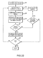
- FIGS. 21-27 are flow diagrams illustrative of various exemplary embodiments of ALI-based methods for lesion assessment in tissue in accordance with the present teachings.
- FIG. 28 is a schematic diagram of a visualization, mapping, and 3D navigation system in accordance with the present teachings.
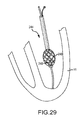
- FIG. 29 is a diagrammatic view of a multi-electrode, array catheter illustrating one embodiment of a system in accordance with present teachings.
- FIG. 30 is an isometric diagrammatic view of a robotic catheter system illustrating an exemplary layout of various system components in accordance with the present teachings.
- FIG. 31 is an isometric diagrammatic view of an exemplary embodiment of a robotic catheter manipulator support structure in accordance with the present teachings.
- FIG. 32 is a schematic diagram of a magnetic-based catheter manipulation system in accordance with the present teachings.
- FIG. 1 illustrates one embodiment of a system 10 for one or more diagnostic and therapeutic functions including components providing an improved assessment of, among other things, a degree of coupling between an electrode 12 on a catheter 14 and a tissue 16 in a body 17 .
- the degree of coupling can be useful for assessing, among other things, the degree of contact between the electrode 12 and the tissue 16 , the relative proximity of the electrode 12 to the tissue 16 , and the formation of lesions in the tissue 16 .
- the tissue 16 comprises heart or cardiac tissue. It should be understood, however, that the present invention may be used to evaluate coupling between electrodes and a variety of body tissues.
- the electrode 12 is illustrated as part of the catheter 14 , it should be understood that the present invention may be used to assess a degree of coupling between any type of electrode and tissue including, for example, intracardiac electrodes, needle electrodes, patch electrodes, wet brush electrodes (such as the electrodes disclosed in commonly assigned U.S. patent application Ser. No. 11/190,724 filed Jul. 27, 2005, the entire disclosure of which is incorporated herein by reference) and virtual electrodes (e.g., those formed from a conductive fluid medium such as saline including those disclosed in commonly assigned U.S. Pat. No. 7,326,208 issued Feb. 5, 2008, the entire disclosure of which is incorporated herein by reference).
- intracardiac electrodes such as the electrodes disclosed in commonly assigned U.S. patent application Ser. No. 11/190,724 filed Jul. 27, 2005, the entire disclosure of which is incorporated herein by reference
- virtual electrodes e.g., those formed from a conductive fluid medium such as saline including those disclosed in commonly assigned
- the system 10 may include patch electrodes 18 , 20 , 22 , an ablation generator 24 , a tissue sensing circuit 26 , an electrophysiology (EP) monitor 28 , and a system 30 for visualization, mapping and navigation of internal body structures which may include an electronic control unit 32 in accordance with the present invention and a display device 34 , among other components.
- the catheter 14 is provided for examination, diagnosis and treatment of internal body tissues such as the tissue 16 .
- the catheter 14 comprises an ablation catheter and, more particularly, an irrigated radio-frequency (RF) ablation catheter.
- RF radio-frequency
- the catheter 14 is connected to a fluid source 36 having a biocompatible fluid such as saline through a pump 38 (which may comprise, for example, a fixed rate roller pump or variable volume syringe pump with a gravity feed supply from the fluid source 36 as shown) for irrigation.
- the catheter 14 is also electrically connected to the ablation generator 24 for delivery of RF energy.
- the catheter 14 may include a cable connector or interface 40 , a handle 42 , a shaft 44 having a proximal end 46 and a distal 48 end (as used herein, “proximal” refers to a direction toward the end of the catheter near the clinician, and “distal” refers to a direction away from the clinician and (generally) inside the body of a patient) and one or more electrodes 12 , 50 , 52 .
- the catheter 14 may also include other conventional components not illustrated herein such as a temperature sensor, additional electrodes, and corresponding conductors or leads.
- the connector 40 provides mechanical, fluid and electrical connection(s) for cables 54 , 56 extending from the pump 38 and the ablation generator 24 .
- the connector 40 is conventional in the art and is disposed at a proximal end of the catheter 14 .
- the handle 42 provides a location for the clinician to hold the catheter 14 and may further provide means for steering or the guiding shaft 44 within the body 17 .
- the handle 42 may include means to change the length of a guidewire extending through the catheter 14 to the distal end 48 of the shaft 44 to steer the shaft 44 .
- the handle 42 is also conventional in the art and it will be understood that the construction of the handle 42 may vary.
- the catheter 14 may be robotically driven or controlled. Accordingly, rather than a clinician manipulating a handle to steer or guide the catheter 14 , and the shaft 44 thereof, in particular, a robot is used to manipulate the catheter 14 .
- the shaft 44 is an elongated, tubular, flexible member configured for movement within the body 17 .
- the shaft 44 support the electrodes 12 , 50 , 52 , associated conductors, and possibly additional electronics used for signal processing or conditioning.
- the shaft 44 may also permit transport, delivery and/or removal of fluids (including irrigation fluids and bodily fluids), medicines, and/or surgical tools or instruments.
- the shaft 44 may be made from conventional materials such as polyurethane and defines one or more lumens configured to house and/or transport electrical conductors, fluids or surgical tools.
- the shaft 44 may be introduced into a blood vessel or other structure within the body 17 through a conventional introducer.
- the shaft 44 may then be steered or guided through the body 17 to a desired location such as the tissue 16 with guidewires or other means known in the art.
- the electrodes 12 , 50 , 52 are provided for a variety of diagnostic and therapeutic purposes including, for example, electrophysiological studies, catheter identification and location, pacing, cardiac mapping and ablation.
- the catheter 14 includes an ablation tip electrode 12 at the distal end 48 of the shaft 44 , and a pair of ring electrodes 50 , 52 . It should be understood, however, that the number, shape, orientation and purpose of the electrodes 12 , 50 , 52 may vary.
- the patch electrodes 18 , 20 , 22 provide RF or navigational signal injection paths and/or are used to sense electrical potentials.
- the electrodes 18 , 20 , 22 may also have additional purposes such as the generation of an electromechanical map.
- the electrodes 18 , 20 , 22 are made from flexible, electrically conductive material and are configured for affixation to the body 17 such that the electrodes 18 , 20 , 22 are in electrical contact with the patient's skin.
- the electrode 18 may function as an RF indifferent/dispersive return for the RF ablation signal.
- the electrodes 20 , 22 may function as returns for the RF ablation signal source and/or an excitation signal generated by the tissue sensing circuit 26 as described in greater detail below.
- the electrodes 20 , 22 are preferably spaced relatively far apart.
- the electrodes 20 , 22 are located on the medial aspect of the left leg and the dorsal aspect of the neck.
- the electrodes 20 , 22 may alternatively be located on the front and back of the torso or in other conventional orientations.
- the ablation generator 24 generates, delivers, and controls RF energy output by the ablation catheter 14 .
- the generator 24 is conventional in the art and may comprise the commercially available unit sold under the model number IBI-1500T RF Cardiac Ablation Generator, available from Irvine Biomedical, Inc.
- the generator 24 includes an RF ablation signal source 54 configured to generate an ablation signal that is output across a pair of source connectors: a positive polarity connector SOURCE (+) which may connect to the tip electrode 12 ; and a negative polarity connector SOURCE( ⁇ ) which may be electrically connected by conductors or lead wires to one of the patch electrodes 18 , 20 , 22 (see FIG. 2 ).
- the source 54 is configured to generate a signal at a predetermined frequency in accordance with one or more user specified parameters (e.g., power, time, etc.) and under the control of various feedback sensing and control circuitry as is know in the art.
- the source 54 may generate a signal, for example, with a frequency of about 450 kHz or greater.
- the generator 24 may also monitor various parameters associated with the ablation procedure including impedance, the temperature at the tip of the catheter, ablation energy and the position of the catheter and provide feedback to the clinician regarding these parameters.
- the impedance measurement output by the generator 24 reflects the magnitude of impedance not only at the tissue 16 , but the entire impedance between the tip electrode 12 and the corresponding patch electrode 18 on the body surface.
- the impedance output by the generator 24 is also not easy to interpret and correlate to tissue contact by the clinician.
- the ablation generator 24 may generate a higher frequency current for the purposes of RF ablation, and a second lower frequency current for the purpose of measuring impedance.
- the tissue sensing circuit 26 provides a means, such as a tissue sensing signal source 61 , for generating an excitation signal used in impedance measurements and means, such as a complex impedance sensor 58 , for resolving the detected impedance into its component parts.
- the signal source 61 is configured to generate an excitation signal across source connectors SOURCE(+) and SOURCE ( ⁇ ) (See FIG. 2 ).
- the source 61 may output a signal having a frequency within a range from about 1 kHz to over 500 kHz, more preferably within a range of about 2 kHz to 200 kHz, and even more preferably about 20 kHz.
- the excitation signal is a constant current signal, preferably in the range of between 20-200 ⁇ A, and more preferably about 100 ⁇ A.
- the constant current AC excitation signal generated by the source 61 is configured to develop a corresponding AC response voltage signal that is dependent on the complex impedance of the tissue 16 and is sensed by the complex impedance sensor 58 .
- the complex impedance is resolved into its component parts (i.e., the resistance (R) and reactance (X) or the impedance magnitude (
- Sensor 58 may include conventional filters (e.g., bandpass filters) to block frequencies that are not of interest, but permit appropriate frequencies, such as the excitation frequency, to pass, as well as conventional signal processing software used to obtain the component parts of the measured complex impedance.
- the excitation signal may be an AC voltage signal where the response signal comprises an AC current signal. Nonetheless, a constant current excitation signal is preferred as being more practical. While in some situations there can be advantages to having an excitation signal frequency at or near the frequency of the RF ablation signal, it should be appreciated that the excitation signal frequency is preferably outside of the frequency range of the RF ablation signal, which allows the complex impedance sensor 58 to more readily distinguish the two signals, and facilitates filtering and subsequent processing of the AC response voltage signal. Alternatively, the system can cycle each signal (RF ablation and excitation) on and off in alternating periods so they do not overlap in time.
- the excitation signal frequency is also preferably outside the frequency range of conventionally expected electrogram (EGM) signals in the frequency range of 0.05 Hz-1 kHz.
- the excitation signal preferably has a frequency that is preferably above the typical EGM signal frequencies and below the typical RF ablation signal frequencies.
- the circuit 26 is also connected, for a purpose described below, across a pair of sense connectors: a positive polarity connector SENSE (+) which may connect to the tip electrode 12 ; and a negative polarity connector SENSE ( ⁇ ) which may be electrically connected to one of the patch electrodes 18 , 20 , 22 (see FIG. 2 ; note, however, that the connector SENSE ( ⁇ ) should be connected to a different electrode of the electrodes 18 , 20 , 22 relative to the connector SOURCE ( ⁇ ) as discussed below).
- the term connectors as used herein does not imply a particular type of physical interface mechanism, but is rather broadly contemplated to represent one or more electrical nodes.
- connectors SOURCE (+), SOURCE ( ⁇ ), SENSE (+) and SENSE ( ⁇ ) form a three terminal arrangement permitting measurement of the complex impedance at the interface of the tip electrode 12 and the tissue 16 .
- is the magnitude of the complex impedance (expressed in ohms) and ⁇ Z ⁇ is the phase angle expressed in radians. Alternatively, the phase angle may be expressed in terms of degrees where
- phase angle will be preferably referenced in terms of degrees.
- the three terminals comprise: (1) a first terminal designated “A-Catheter Tip” which is the tip electrode 12 ; (2) a second terminal designated “B-Patch 1 ” such as the source return patch electrode 22 ; and (3) a third terminal designated “C-Patch 2 ” such as the sense return patch electrode 20 .
- the excitation signal generated by the source 61 in the tissue sensing circuit 26 is also be applied across the source connectors (SOURCE (+), SOURCE( ⁇ )) for the purpose of inducing a response signal with respect to the load that can be measured and which depends on the complex impedance.
- SOURCE (+), SOURCE( ⁇ ) source connectors
- a 20 kHz, 100 ⁇ A AC constant current signal is sourced along a path 60 , as illustrated, from one connector (SOURCE (+), starting at node A) through the common node (node D) to a return patch electrode (SOURCE ( ⁇ ), node B).
- the complex impedance sensor 58 is coupled to the sense connectors (SENSE (+), SENSE ( ⁇ )), and is configured to determine the impedance across a path 62 .
- the circuit pathways between the catheter tip electrode 12 and the patch electrodes will overlap significantly and impedance measured at the common node (i.e., node D) will reflect impedances not only at the interface of the catheter electrode 12 and the tissue 16 , but also other impedances between the tissue 16 and the surface of body 17 .
- the patch electrodes are moved further apart, the amount of overlap in the circuit paths decreases and impedance measured at the common node is only at or near the tip electrode 12 of the catheter 14 .
- FIG. 3 is a simplified schematic and block diagram of the three-terminal measurement arrangement of the invention.
- the SOURCE (+) and SENSE (+) lines may be joined in the catheter connector 40 or the handle 42 (as in solid line) or may remain separate all the way to the tip electrode 12 (the SENSE (+) line being shown in phantom line from the handle 42 to the tip electrode 12 ).
- FIG. 3 shows, in particular, several sources of complex impedance variations, shown generally as blocks 64 , that are considered “noise” because such variations do not reflect the physiologic changes in the tissue 16 or electrical coupling whose complex impedance is being measured.
- the tissue 16 whose complex impedance is being measured is that near and around the tip electrode 12 and is enclosed generally by a phantom-line box 66 (and the tissue 16 is shown schematically, in simplified form, as a resistor/capacitor combination).
- One object of the invention is to provide a measurement arrangement that is robust or immune to variations that are not due to changes in or around the box 66 .
- the variable complex impedance boxes 64 that are shown in series with the various cable connections (e.g., in the SOURCE (+) connection, in the SOURCE ( ⁇ ) and SENSE ( ⁇ ) connections, etc.) may involve resistive/inductive variations due to cable length changes, cable coiling and the like.
- variable complex impedance boxes 64 that are near the patch electrodes 20 , 22 may be more resistive/capacitive in nature, and may be due to body perspiration and the like over the course of a study.
- the various arrangements of the invention are relatively immune to the variations in the blocks 64 , exhibiting a high signal-to-noise (S/N) ratio as to the complex impedance measurement for the block 66 .
- the SOURCE ( ⁇ ) and SENSE ( ⁇ ) returns are illustrated in FIG. 3 as patch electrodes 20 , 22 , it should be understood that other configurations are possible.
- the indifferent/dispersive return electrode 18 can be used as a return as well as another electrode 50 , 52 on the catheter 14 , such as the ring electrode 50 as described in commonly assigned U.S. patent application Ser. No. 11/966,232 filed on Dec. 28, 2007 and titled “System and Method for Measurement of an Impedance Using a Catheter such as an Ablation Catheter,” the entire disclosure of which is incorporated herein by reference.
- the EP monitor 28 is provided to display electrophysiology data including, for example, an electrogram.
- the monitor 28 is conventional in the art and may comprise an LCD or CRT monitor or another conventional monitor.
- the monitor 28 may receive inputs from the ablation generator 24 as well as other conventional EP lab components not shown in the illustrated embodiment.
- the system 30 is provided for visualization, mapping, and navigation of internal body structures.
- the system 30 may comprise the system having the model name EnSite NavXTM and commercially available from St. Jude Medical, Inc. and as generally shown with reference to commonly assigned U.S. Pat. No. 7,263,397 titled “Method and Apparatus for Catheter Navigation and Location and Mapping in the Heart,” the entire disclosure of which is incorporated herein by reference.
- Other systems may include the Biosense Webster CartoTM System, commonly available fluoroscopy systems, or a magnetic location system such as the gMPS system from Mediguide Ltd.
- the system 30 may include the electronic control unit (ECU) 32 and the display device 34 among other components.
- the ECU 32 is a separate and distinct component that is electrically connected to the system 30 .
- the ECU 32 is provided to acquire values for first and second components of a complex impedance between the catheter tip electrode 12 and the tissue 16 and to calculate an electrical coupling index (ECI) responsive to the values with the coupling index indicative of a degree of coupling between the electrode 12 and the tissue 16 .
- the ECU 32 preferably comprises a programmable microprocessor or microcontroller, but may alternatively comprise an application specific integrated circuit (ASIC).
- the ECU 32 may include a central processing unit (CPU) and an input/output (I/O) interface through which the ECU 32 may receive a plurality of input signals including signals from the sensor 58 of the tissue sensing circuit 26 and generate a plurality of output signals including those used to control the display device 34 .
- the ECU 32 may be programmed with a computer program (i.e., software) encoded on a computer storage medium for determining a degree of coupling between the electrode 12 on the catheter 14 and the tissue 16 in the body 17 .
- the program includes code for calculating an ECI responsive to values for first and second components of the complex impedance between the catheter electrode 12 and the tissue 16 with the ECI indicative of a degree of coupling between the catheter electrode 12 and the tissue 16 .
- the ECU 32 acquires one or more values for two component parts of the complex impedance from signals generated by the sensor 58 of the tissue sensing circuit 26 (i.e., the resistance (R) and reactance (X) or the impedance magnitude (
- the ECU 32 combines values for the two components into a single ECI that provides an improved measure of the degree of coupling between the electrode 12 and the tissue 16 and, in particular, the degree of electrical coupling between the electrode 12 and the tissue 16 .
- the single ECI may provide an improved measure of the proximity of the electrode 12 relative to the tissue 16 , as well as improved assessment of lesion formation in the tissue 16 .
- the “mean value” for the resistance or reactance may refer to the average of N samples of a discrete time signal x i or a low-pass filtered value of a continuous x(t) or discrete x(t i ) time signal.
- the “standard deviation” for the resistance or reactance may refer to the standard deviation, or equivalently root mean square (rms) about the mean or average of N samples of a discrete time signal x i or the square root of a low pass filtered value of a squared high pass filtered continuous x(t) or discrete x(t i ) time signal.
- the “peak to peak magnitude” for the resistance or reactance may refer to the range of the values over the previous N samples of the discrete time signal x i or the k th root of a continuous time signal [abs(x(t))] k that has been low pass filtered for sufficiently large k>2. It was further determined that, while clinician sense also accounted for significant variation in pacing threshold (48.7%)—and thus provided a good measure for assessing coupling—the combination of the ECI with clinician sense further improved assessment of coupling (accounting for 56.8% of pacing threshold variation).
- ECI a*R mean+ b*X mean+ c.
- ECI R mean ⁇ 5.1 *X mean (3)
- Rmean is the mean value of a plurality of resistance values
- Xmean is the mean value of a plurality of reactance values. It should be understood, however, that other values associated with the impedance components, such as a standard deviation of a component or peak to peak magnitude of a component which reflect variation of impedance with cardiac motion or ventilation, can also serve as useful factors in the ECI.
- the ECI could also be based on values associated with the polar coordinates impedance magnitude (
- coefficients, offsets and values within the equation for the ECI may vary depending on, among other things, the specific catheter used, the patient, the equipment, the desired level of predictability, the species being treated, and disease states. In accordance with the present invention, however, the coupling index will always be responsive to both components of the complex impedance in order to arrive at an optimal assessment of coupling between the catheter electrode 12 and the tissue 16 .
- Validation testing was also performed in a human trial featuring twelve patients undergoing catheter ablation for atrial fibrillation.
- the patients were treated using an irrigated, 7 French radio frequency (RF) ablation catheter with a 4 mm tip electrode operating at a standard setting of a 50° C. tip temperature, 40 W power, and 30 ml/min. flow rate (adjusted accordingly proximate the esophagus).
- RF radio frequency
- electrogram amplitudes and pacing thresholds were obtained for comparison. Each measure yielded corresponding changes in value as the catheter electrode moved from a no-contact position to a contact position.
- electrogram amplitudes increased from 0.14+/ ⁇ 0.16 to 2.0+/ ⁇ 1.9 mV
- pacing thresholds decreased from 13.9+/ ⁇ 3.1 to 3.1+/ ⁇ 20 mA
- the ECI increased from 118+/ ⁇ 15 to 145+/ ⁇ 24 (with resistance increasing from 94.7+/ ⁇ 11.0 to 109.3+/ ⁇ 15.1 ⁇ and reactance decreasing from ⁇ 4.6+/ ⁇ 0.9 to ⁇ 6.9+/ ⁇ 2 ⁇ ).
- the ECI increased (and resistance increased and reactance decreased) as the catheter electrode was moved from a “no-contact” (115+/ ⁇ 12) position to “light,” (135+/ ⁇ 15) “moderate,” (144+/ ⁇ 17) and “firm” (159+/ ⁇ 34) positions.
- the calculated ECI and clinician sense of coupling were again compared to pacing threshold as an approximation of the degree of coupling.
- a regression analysis was performed using a logarithm of the pacing threshold as the response and various impedance parameters and clinician sense as predictors. From this analysis, it was determined that clinician sense accounted for approximately 47% of the variability in pacing threshold.
- the addition of the ECI however, with clinician sense resulted in accounting for approximately 51% of the variability in pacing threshold—further demonstrating that the ECI can assist clinicians in assessing coupling between the catheter electrode 12 and the tissue 16 .
- FIGS. 4-5 a series of timing diagrams (in registration with each other) illustrate a comparison of atrial electrograms relative to changes in resistance and reactance ( FIG. 4 ) and the composite ECI ( FIG. 5 ).
- atrial electrograms are one traditional measurement for assessing coupling between the catheter electrode 12 and the tissue 16 .
- the signal amplitude of the atrial electrogram (labeled “ABL D-2” in FIG. 4 ) increases when the catheter electrode 12 moves from a position of “no contact” to “contact” with the tissue 16 .
- measured resistance (R) increases and reactance (X) decreases and become more variable ( FIG. 4 ) and the calculated ECI increases ( FIG. 5 ), further demonstrating the utility of the ECI in assessing coupling between the electrode 12 and the tissue 16 .
- the human validation testing also revealed that the ECI varied depending on tissue types. For example, the ECI tended to be higher when the catheter electrode was located inside a pulmonary vein than in the left atrium.
- the ECI may be used in identifying among tissue types (e.g., to identify vascular tissue as opposed to trabeculated and myocardial tissue).
- tissue types e.g., to identify vascular tissue as opposed to trabeculated and myocardial tissue.
- force sensors may not adequately estimate the amount of energy delivered into tissue in constrained regions, such as the pulmonary vein or trabeculae
- the inventive ECI may provide a more meaningful measure of ablation efficacy than force sensors.
- a particular location indicates a low reading on a force sensor but a high ECI reading
- a mapping system allows the system to map tissue types on the 3D map, as well as differentiate between trabeculated tissue or constrained regions and smooth tissue with significant electrode applied force.
- the catheter 14 may include a memory such as an EEPROM that stores numerical values for the coefficients and offsets or stores a memory address for accessing the numerical values in another memory location (either in the catheter EEPROM or in another memory).
- the ECU 32 may retrieve these values or addresses directly or indirectly from the memory and modify the ECI accordingly.
- the physical structure of the patient is another factor that may influence impedance measurements and the ECI. Therefore, the ECU 32 may also be configured to offset or normalize the ECI (e.g., by adjusting coefficients or offsets within the index) responsive to an initial measurement of impedance or another parameter in a particular patient. In addition, it may be beneficial to obtain and average values for the ECI responsive to excitation signals generated by the source 61 at multiple different frequencies.
- the display device 34 is provided to present the ECI in a format useful to the clinician.
- the device 34 may also provide a variety of information relating to visualization, mapping, and navigation, as is known in the art, including measures of electrical signals, two and three dimensional images of the tissue 16 , and three-dimensional reconstructions of the tissue 16 .
- the device 34 may comprise an LCD monitor or other conventional display device.
- the ECI may be displayed in one or more ways to provide easy interpretation and correlation to tissue contact and/or proximity of the electrode 12 to the tissue 16 for the clinician. Referring to FIG. 6 , the ECI may be displayed as a scrolling waveform 68 .
- the ECI may also be displayed as a meter 70 which displays the one second average value of the ECI.
- upper and lower thresholds 72 , 74 may be set (either pre-programmed in the ECU 32 or input by the user using a conventional I/O device). Characteristics of the waveform 68 and/or the meter 70 may change depending upon whether the value of the ECI is within the range set by the thresholds (e.g., the waveform 68 or the meter 70 may change colors, such as from green to red, if the value of the ECI moves outside of the range defined by the thresholds).
- Changes to the ECI may also be reflected in changes to the image of the catheter 14 and/or the catheter electrode 12 on the display device 34 .
- the catheter electrode 12 may be displayed on the screen (including within a two or three dimensional image or reconstruction of the tissue) as a beacon 76 .
- the appearance of the beacon 76 may change.
- the color of the beacon 76 may change (e.g., from green to red) and/or lines may radiate outwardly from the beacon 76 as the index falls above, below or within a range of values.
- the length of the splines of the beacon 76 may continuously vary with the ECI.
- the degree of coupling between a catheter electrode 12 and the tissue 16 may be assessed through several method steps in accordance with one embodiment of the invention.
- an excitation signal is applied between the electrode 12 and a reference electrode such as the patch electrode 22 between connectors SOURCE (+) and SOURCE ( ⁇ ) along the first path 60 (see FIG. 2 ).
- the signal source 61 of the tissue sensing circuit 26 may generate the excitation signal at a predetermined frequency or frequencies. This action induces a voltage along the path 62 between the electrode 12 and another reference electrode such as the patch electrode 20 .
- the voltage may be measured by the sensor 58 which resolves the sensed voltage into component parts of the complex impedance at the tissue 16 .
- the ECU 32 acquires values for the components of the complex impedance.
- the ECU 32 then calculates a ECI responsive to the values that is indicative of a degree of coupling between the electrode 12 and the tissue 16 .
- the index may then be presented to a clinician in a variety of forms including by display on the display device 34 as, for example, the waveform 68 , the meter 70 , or the beacon 76 .
- an ECI formed in accordance with the teaching of the present invention may be useful in a variety of applications. As shown in the embodiment illustrated in FIG. 1 , the ECI can be used as part of the system 10 for ablation of the tissue 16 .
- the ECI provides an indication of the degree of electrical coupling between the tip electrode 12 and the tissue 16 , thereby assisting in the safe and effective delivery of ablation energy to the tissue 16 .
- the ECI may further provide an indication of the proximity or orientation of the tip electrode 12 to the adjacent tissue 16 .
- the signal source 61 of the sensing circuit 26 may generate excitation signals across source connectors SOURCE (+) and SOURCE ( ⁇ ) defined between the tip electrode 12 and the patch electrode 22 , and also between the ring electrode 50 and the patch electrode 22 .
- the impedance sensor 58 may then measure the resulting voltages across sense connectors SENSE (+) and SENSE ( ⁇ )) defined between the tip electrode 12 and the patch electrode 20 , and also between the ring electrode 50 and the patch electrode 22 .
- the measurements for the tip 12 and the ring 50 are taken at different frequencies or times.
- the ECU 32 may compare the measured values directly or, more preferably, determine an ECI for each of the electrodes 12 , 50 responsive to the measured values, and compare the two ECIs. Differences between the measured impedance or ECI for the electrodes 12 , 50 may indicate that the electrode 12 is disposed at an angle (as well as the degree of that angle) relative to the tissue 16 .
- the electrode 50 is used for exemplary purposes only. Similar results could be obtained with other electrodes disposed proximate the tip electrode 12 or from using a split tip electrode.
- the ECI may provide an indication of proximity or orientation of the catheter's tip to adjacent tissue by employing two or more electrodes near the tip.
- the tip electrode 12 is used together with and adjacent the ring electrode 50 to provide two independent measures of complex impedance and ECI. This is accomplished in the manner described with respect to FIGS. 1-3 , but relies on separate SOURCE and SENSE circuits and connections that operate on different frequencies, or that are time division multiplexed to achieve independence.
- Cutaneous patch electrodes 20 , 22 may be used in common for both tip and ring electrode impedance and ECU determinations.
- the ECU 32 may employ the two impedance measurements directly or operate on the difference of the impedances or ECIs. When in non-contact and of a defined proximity region, the tip and ring ECIs will both be constant and exhibit a fixed difference (depending on electrode design). Changes in this differential impedance or ECI reflect proximity of one (or both) electrodes to tissue. Once the tip electrode is in contact, the value of the differential ECI may indicate the angle of incidence of the catheter tip with tissue. Similar results could be obtained from other electrodes disposed near the tip electrode 12 or from using a split-tip electrode.
- the present invention may also be used as a proximity sensor to assess or determine the proximity of the electrode 12 to the tissue 16 , as well as to assess the formation of lesions in the tissue 16 .
- proximity assessment as an electrode, such as the electrode 12 , approaches the tissue 16 , the impedance changes as does the ECI. The ECI is therefore indicative of the proximity of the electrode 12 to the tissue 16 .
- the general position (with a frame of reference) and speed of the tip of the catheter 14 and the electrode 12 are known (although the proximity of the electrode 12 to the tissue 16 is unknown).
- this information can be combined to define a value (the “electrical coupling index rate” or ECIR) that is indicative of the rate of change in the ECI as the electrode 12 approaches the tissue 16 and which may provide an improved measure of the proximity of the electrode 12 to the tissue 16 .
- This information can be used, for example, in robotic catheter applications to slow the rate of approach prior to contact, and also in connection with a transseptal access sheath having a distal electrode to provide an indication that the sheath is approaching (and/or slipping away from) the septum.
- the raw calculated ECI may be used to assess the proximity of the electrode 12 to the tissue 16 .
- This particular embodiment provides a relatively simple discrimination of proximity.
- the ECU 32 calculates the ECI as described in detail above.
- the calculated ECI may then be used to assess the proximity of the electrode 12 to the tissue 16 .
- FIG. 7 illustrates an exemplary embodiment of a method for assessing the proximity using the ECI.
- a current ECI is calculated in a first step 78 .
- the calculated ECI is evaluated to determine whether the electrode 12 is within a predetermined distance from the tissue 16 , in contact with the tissue 16 , or further away from the tissue 16 than the predetermined distance. More particularly, in a first substep 82 of second step 80 , an ECI range 84 is defined that correlates to a predetermined distance from the tissue 16 .
- the predetermined distance is 2 mm
- the ECI range 84 has a first threshold value 86 that corresponds to 0 mm from the tissue 16 (i.e., the electrode is in contact with the tissue), and a second threshold value 88 that corresponds to location that is 2 mm from the tissue 16 .
- These thresholds may be set by either preprogramming them into the ECU 32 , or a user may input them using a conventional I/O device.
- the calculated ECI is compared to the predefined ECI range 84 . Based on this comparison, the relative proximity of the electrode 12 is determined.
- the electrode 12 is deemed to be in “close proximity” of the tissue 16 . In this particular embodiment, if the electrode is within 0-2 mm of the tissue, it is deemed to be in “close proximity.” If the calculated ECI falls below the first threshold value 86 , then the electrode 12 is deemed to be in contact with the tissue 16 . Finally, if the calculated ECI falls outside of the second threshold value 88 , then the electrode 12 is deemed to not be in close proximity of the tissue 16 , but rather is further away than the predetermined distance, which, in this embodiment would mean that the electrode 12 is further than 2 mm from the tissue 16 .
- FIGS. 8 a and 8 b are provided to illustrate how the above described methodology may be applied.
- FIG. 8 a illustrates examples of the results of ECI calculations that are meant to correspond to calculations representing three different angles of approach—0, 60, and 90 degrees—of the electrode 12 to the tissue 16 .
- FIG. 8 b illustrates examples of the results of ECI calculations that are meant to correspond to calculations resulting from the use of different types of catheters (i.e., CATH A, CATH B, and CATH C), which may influence the ECI calculations.
- CATH A, CATH B, and CATH C which may influence the ECI calculations.
- the illustrated calculations do not correspond to actual test data or calculations made during an actual procedure, but rather are provided solely for illustrative purposes. In this example, the predetermined distance from the heart that is deemed to be “close proximity” was 0 to 2 mm.
- the calculations for each angle of approach are fairly consistent with each other.
- a single ECI range 84 may be defined that can be compared to any calculated ECI regardless of the angle of approach.
- the ECI range 84 is defined by the first threshold 86 having a value of 135, which corresponds to 0 mm from the tissue 16 , and the second threshold 88 having a value of 125, which corresponds to 2 mm from the tissue 16 .
- the ECI is below 125, the second threshold 88 of the ECI range 84 , and is relatively stable. As the electrode 12 approaches the tissue 16 , however, the ECI begins to increase.
- the ECI is around 125, which, again, is the second threshold 88 of the ECI range 84 .
- the ECI continues to increase.
- the ECI is at the first threshold 86 of approximately 135.
- the illustrated calculations are spaced apart, as opposed to being closely grouped together.
- a single ECI range 84 cannot be defined that would allow for the comparison with any calculated ECI.
- a number of factors may contribute to the spacing out of the calculations. For example, the type of catheter used, the particular environment in which the calculations are made, attributes of the patient, etc. may all contribute to the resulting spacing out of the calculations.
- an offset is used. More particularly, if one or more contributory factors are present, the clinician is able to enter such information into the ECU 32 via a user interface for example, which will then be configured to add or subtract a defined offset from one or both of the calculated ECI and/or the ECI range.
- ECU 32 may be programmed with one or more offsets, or the offset(s) may be entered by a user using a conventional I/O interface. Accordingly, in one exemplary embodiment, rather than simply comparing the ECI to an ECI range, an offset is added to or subtracted from either the ECI range, or the calculated ECI itself. In either instance, the added or subtracted offset performs a scaling function that allows for the comparison described above to be made.
- the ECI range 84 is a baseline ECI range defined by the first threshold 86 having a value of 135, which corresponds to 0 mm from the tissue 16 , and the second threshold 88 having a value of 125, which corresponds to 2 mm from the tissue 16 . If the particular procedure is one in which an offset would apply, the ECU 32 makes the necessary adjustments, and then the methodology continues as described above with respect to FIG. 7 . When the electrode is more than approximately 2 mm away from the tissue 16 , the ECI is below 125, the second threshold 88 of the ECI range 84 , and is relatively stable. As the electrode 12 approaches the tissue 16 , however, the ECI begins to increase.
- the ECI is around 125, which, again, is the second threshold 88 of the ECI range 84 .
- the ECI continues to increase.
- the ECI is at the first threshold 86 of approximately 135.
- the ECI (whether as calculated and/or with an offset) and comparing it to the ECI range representing a predetermined distance from the tissue 16 (which may include an offset depending on the circumstances), one can easily determine whether the electrode 12 is in contact with, in close proximity to, or far away from the heart tissue 16 .
- the rate of change of the ECI rather than comparing a calculated finite ECI to a predefined range, the rate of change of the ECI
- the electrode 12 may be evaluated and used to assess the proximity of the electrode 12 to the tissue 16 .
- the rate of change in the ECI is greater than when either in contact with or far away from the tissue 16 . Accordingly, it follows that when the rate of change of the ECI over a predetermined period of time is within a certain range or equals a particular rate, one may be able to determine whether the electrode 12 is within a predetermined distance or in close proximity to the tissue 16 .
- FIG. 9 illustrates one exemplary embodiment of a methodology that uses the rate of change of the ECI.
- a storage medium 92 i.e., memory 92
- the memory 92 may be part of the ECU 32 (See FIG. 1 ), or may be a separate component (or part of another component) that is accessible by the ECU 32 such that the ECU 32 may retrieve the stored ECIs.
- the ECU 32 is configured to access the memory 92 and to calculate the rate of change in the ECI or the slope of a line drawn between a current or most recent ECI calculation and one or more previously calculated ECIs. If the rate of change or slope meets a predetermined value or falls within a predetermined or predefined range, then the ECU 32 will recognize that the ECI has changed at a certain rate, and therefore, that electrode 12 is within a certain distance of the tissue 16 .
- a current ECI is calculated.
- the ECU 32 accesses the memory 92 to retrieve one or more previously calculated ECIs.
- the rate of change/slope between the current ECI and the one or more previously calculated ECIs is calculated.
- the ECU 32 determines whether the electrode 12 is in close proximity to the tissue 16 based on the rate of change in the ECI.
- This embodiment is particularly useful because the raw ECI is not being directly compared to a range of ECIs. Rather, because it is a rate of change or slope calculation, it does not matter what the magnitude of the ECI is, as it is the rate of change of the ECI that is being evaluated. Accordingly, it provides a more normalized approach for assessing proximity.
- the system 10 is further configured to provide an indication to the clinician manipulating the catheter 14 or to a controller of a robotically controlled device that drives the catheter 14 that the electrode 12 is in “close proximity” to the tissue 16 .
- the ECU 32 is configured to generate a signal representative of an indicator that the electrode 12 is within the certain predetermined distance of the tissue 16 (e.g., 0-2 mm). In such an instance, this indicator indicates that the electrode 12 is in close proximity of the tissue 16 and allows the clinician or robotic controller to adjust its conduct accordingly (e.g., slow down the speed of approach).
- Such an indicator may be visually displayed on the display 34 of the system in the same manner described above with respect to the display of the ECI, may be displayed in a graphical form, may be in the form of an audible warning, or may comprise any other known indicators.
- the signal may be transmitted by the ECU 32 to a controller of the robotic device, which receives and processes the signal and then adjusts the operation of the robot as necessary.
- the ECU 32 may also provide indicators that the electrode 12 is far away from the tissue 16 (i.e., further away than a predetermined distance), and/or that the electrode 12 is in contact with the tissue 16 .
- the ECI may be used, in part, to calculate an electrical coupling index rate (ECIR).
- ECIR electrical coupling index rate
- the resulting ECIR can, in turn, be used to assess the proximity of the electrode 12 to the tissue 16 .
- the ECU 32 is configured to calculate the ECIR, however, in other exemplary embodiments other processors or components may be used to perform the calculation. As will be described below, this particular embodiment provides a graded level of proximity.
- the ECIR is calculated by dividing the change in ECI by the change in distance or position of the electrode 12 over a predetermined period of time. More specifically, the ECIR is calculated using the following equation (4):
- s is the length of the path of the electrode in three-dimensional space (i.e., change in distance or position).
- the change in the ECI is calculated by sampling the ECI calculations performed by the ECU 32 (these calculations are described in great detail above) at a predetermined rate and then determining the difference between a current calculation and the most recent previous calculation, for example, that may be stored in a storage medium that is part of accessible by the ECU 32 . In another exemplary embodiment, however, the difference may be between a current calculation and multiple previous calculations, or an average of previous calculations.
- the ECU 32 samples the calculated ECI every 10 to 30 ms, and then calculates the change in the ECI over that time interval
- the ECI may be sampled at rates other than that described above, and that such rates are provided for exemplary purposes only.
- the sampling is timed or synchronized to coincide with the cardiac cycle so as to always sample at the same point in the cardiac cycle, thereby avoiding variances due to the cardiac cycle.
- the sampling of the ECI is dependent upon a triggering event, as opposed to being a defined time interval.
- the sampling of the ECI is dependent upon the change in the distance/position of the electrode 12 meeting a particular threshold. More particularly, when the system 10 determines that the electrode has moved a predetermined distance, the ECU 32 will then sample the ECI over the same period of time in which the electrode 12 moved. Accordingly, it will be appreciated by those of ordinary skill in the art that many different sampling rates and/or techniques may be employed to determine the change in the ECI.
- this change may be calculated by the ECU 32 based on location coordinates provided to it by the system 30 (i.e., x, y, z coordinates provided by the mapping, visualization, and navigation system 30 ), or may be calculated by the system 30 and then provided to the ECU 32 .
- the change in distance or location is determined by sampling the location coordinates of the electrode 12 at a predetermined rate. From this, the change in distance over time
- the location coordinates of the electrode 12 are sampled every 10 to 30 ms, and then the change in the location is calculated over that time interval. It will be appreciated by those of ordinary skill in the art that the location/position of the electrode may be sampled at rates other than that described above, and that such rates are provided for exemplary purposes only. For example, in another exemplary embodiment, using techniques well known in the art, the sampling is timed or synchronized to coincide with the cardiac cycle so as to always sample at the same point in the cardiac cycle, thereby avoiding variances due to the cardiac cycle.
- the ECU 32 is able to calculate the ECIR by dividing the change in the ECI by the change in the distance or location of the electrode 12
- the calculated ECIR is saved in a storage medium that is accessible by the ECU 32 .
- the ECIR may be used to assess, among other things, the proximity of the electrode 12 to the tissue 16 .
- the ECIR is calculated in a first step 102 .
- the calculated ECIR is evaluated to determine whether the electrode 12 is within a predetermined distance from the tissue 16 , in contact with the tissue 16 , or further away from the tissue 16 than the predetermined distance.
- a ECIR range 108 is defined that correlates to a predetermined distance from the tissue 16 .
- the predetermined distance is 2 mm
- the ECIR range 108 has a first threshold value 110 that corresponds to 0 mm from the tissue 16 (i.e., the electrode 12 is in contact with the tissue 16 ), and a second threshold value 112 that corresponds to a location that is 2 mm from the tissue 16 .
- These thresholds may be set by either preprogramming them into the ECU 32 , or a user may manually input them into the ECU 32 using a conventional I/O device.
- the calculated ECIR is compared to the predefined range 108 of ECIRs. Based on this comparison, the relative proximity of the electrode 12 is determined. More particularly, if the calculated ECIR is within the range 108 , then the electrode 12 is deemed to be in “close proximity” of the tissue 16 . In this particular embodiment, if the electrode 12 is within 0-2 mm of the tissue 16 , it is deemed to be in “close proximity.” If the calculated ECIR falls below the first threshold value 110 , then the electrode 12 is deemed to be in contact with the tissue 16 .
- the electrode 12 is deemed to not be in close proximity of the tissue 16 , but rather is further away than the predetermined distance, which, in this embodiment would mean that the electrode 12 is further than 2 mm from the tissue 16 .
- FIG. 11 is provided to show how the above described methodology may be applied, and illustrates what a ECIR calculation may look like. It should be noted that the illustrated calculations are not based on actual testing or ECIR calculations made during an actual procedure, but rather are provided solely for illustrative purposes.
- the ECIR range 108 is defined by a first threshold 110 having a value of ⁇ 6.0, which corresponds to 0 mm from the tissue 16 , and a second threshold 112 having a value of ⁇ 0.5, which corresponds to 2 mm from the tissue 16 .
- the predetermined distance from the heart that is deemed to be “close proximity” is 0-2 mm.
- the ECIR becomes negative as the tissue 16 is approached because as the electrode 12 comes closer to the tissue 16 , the ECI increases. Accordingly, the value representing the change in ECI is negative since a higher ECI is subtracted from a lower ECI.
- the ECIR is close to zero (0) and relatively stable, but more particularly hovering between ⁇ 0.5 and +0.5. This is partly because the further away from the tissue 16 the electrode 12 is, the ECIR is less responsive. However, as the electrode 12 approaches the tissue 16 , the ECIR begins to decrease and becomes dramatically more dynamic. When electrode is approximately 2 mm away, the ECIR is around ⁇ 0.5, which is the second threshold 112 of the ECIR range 108 . As the electrode 12 continues to get closer the tissue 12 , and therefore in closer proximity thereto, the ECIR continues to decrease.
- the ECIR when the electrode 12 reaches the tissue 16 and makes initial contact, the ECIR is at ⁇ 6.0, which is the first threshold 110 of the ECIR range 108 .
- the ECIR then begins to stabilize at a level around ⁇ 7.0 that is much lower than the level when the electrode is “far away” from the tissue (i.e., more than 2 mm) and outside of the predetermined ECIR range 108 .
- the rate of change in the ECIR is greater than when the electrode 12 is either in contact with or far away from the tissue 16 . (See FIG. 11 , for example). Accordingly, it follows that when the rate of change of the ECIR over a predetermined period of time is within a certain range or equals particular rate that may be preprogrammed into the ECU 32 or input by a user as described above, one may be able to determine whether the electrode is within a predetermined distance or in close proximity to the tissue.
- the methodology of this particular embodiment may carried out using either one of the calculations represented by equation (5) or equation (6) below:
- the rate of change in the ECIR may be determined by simply calculating the change between two or more ECIR calculations (i.e., equation (5) above).
- a storage medium 116 i.e., memory 116
- the memory 116 may be part of the ECU 32 (See FIG. 1 ), or may be a separate component (or part of another component) that is accessible by the ECU 32 such that the ECU 32 may retrieve the stored ECIRs.
- the ECU 32 is configured to access the memory 116 and to calculate the rate of change of the ECIR or slope of a line drawn between a current or most recent ECIR calculation and one or more prior ECIR calculations. If the rate of change or slope meets a predetermined value or falls with a predetermined range, then the ECU 32 will recognize that the ECIR has changed a certain amount, and therefore, that electrode 12 is within a certain distance of the tissue 16 .
- a current ECIR is calculated.
- the ECU 32 accesses the memory 116 to retrieve one or more previously calculated ECIRs.
- the rate of change or the slope between the current ECIR and one or more previously calculated ECIRs is calculated.
- the ECU 32 determines whether the electrode 12 is in close proximity to the tissue 16 based on the rate of change in the ECIR.
- small changes in the location or position of the electrode 12 and therefore, the corresponding rate of change of the corresponding ECIR, can be taken advantage of to obtain a substantially continuous and robust assessment of proximity between the electrode 12 and the tissue 16 .
- perturbations can be induced or instigated in the position of the electrode 12 either manually by a clinician or by way of a robotic controller.
- These small changes in position of the electrode 12 e.g., on the order of 0.2 mm
- the frequency of these perturbations may be sufficiently high to allow for the effective filtering or smoothing out of errors in the ECIR calculations. This may be beneficial for a number of reasons, such as, for example, to resolve environmental events such as cardiac cycle mechanical events.
- the perturbation frequency would be higher than the frequency of the cardiac cycle.
- the frequency of the perturbations is five to ten perturbations per second.
- the cardiac frequency may be filtered out of, or compensated for, in the calculations so as to smooth out any changes resulting during the cardiac cycle because of the constant movement of the electrode.
- the inducement of the perturbations may be synchronized with or coordinated to occur at one or more points in the cardiac cycle using known methodologies.
- the filtering or smoothing effect described above may be carried out and also allow for the observation of proximity changes as a result of catheter or electrode movement/manipulation or ventilation, for example.
- the inducement of perturbations and the resulting ECIR resulting from such perturbations can be used to filter or smooth variation in signals resulting from cardiac cycle mechanical events, thereby providing a more robust system.
- fast perturbations of the catheter, and therefore, the electrode permit frequent determinations of ECIR.
- motions of the catheter and the electrode towards or away from the tissue permit a filtered derivative of ECIR. Changes over this longer time scale of the gradual distance toward or away from the tissue allow for a good determination of a second spatial derivative of ECI
- this particular methodology represents a two time-scale approach (i.e., fast perturbations of the electrode 12 combined with slow movement of the electrode 12 towards the tissue 16 ).
- FIG. 13 illustrates an exemplary representation of what the output of this methodology looks like, which provides a sound representation of proximity. Such a methodology results in a more robust discriminator of proximity.
- the system 10 may provide an indication to the clinician manipulating the catheter 14 or to a controller of a robotically controlled device driving the catheter 14 that the electrode is in “close proximity” to the tissue 16 .
- the ECU 32 is configured to generate a signal representative of an indicator that the electrode 12 is within the certain predetermined distance of the tissue 16 (e.g., 0-2 mm).
- this indicator indicates that the electrode 12 is in close proximity to the tissue 16 and allows the clinician or robotic controller to adjust its conduct accordingly (e.g., slow down the speed of approach).
- Such an indicator may be visually displayed on the display 34 of the system in the same manner described above with respect to the display of the ECI, may be displayed in graphical form, may be in the form of an audible warning, or may comprise any other known indicators.
- the signal may be transmitted by the ECU 32 to a controller from the robotic device, which receives and processes the signal and then adjusts the operation of the robot as necessary.
- the ECU 32 may also provide indicators that the electrode 12 is far away from the tissue (i.e., further away than a predetermined distance), and/or that the electrode 12 is in contact with the tissue.
- the ECU 32 is programmed with a computer program (i.e., software) encoded on a computer storage medium for assessing and/or determining the proximity of the electrode 12 to the tissue 16 .
- a computer program i.e., software
- the program generally includes code for calculating a ECI responsive to values for first and second components of the complex impedance between the catheter electrode 12 and the tissue 16 , and also code to process ECI in the various ways described above (i.e., comparison of ECI to a predefined range, calculating ECIRs and comparing calculated ECIR to predefined ranges, calculating rate of change in the ECI and evaluating the same, and calculating rate of change in ECIR and evaluating the same, for example).
- ECI can be used to assess the formation of lesions in tissue—and more specifically, whether a particular area of tissue at a particular location has been changed (e.g., ablated)—as a result of an ablation procedure.
- tissue may be deemed to be “changed,” for example, when a transmural lesion is formed in the tissue.
- tissue may be deemed to be unchanged, or at least not sufficiently changed, when no lesion is formed or a lesion is started but not fully formed in the tissue (e.g., the lesion is not transmural).
- Tissue that has been changed can have different electrical and functional properties than otherwise similar unchanged, or at least not sufficiently changed (e.g., unablated or not fully ablated), or virgin tissue.
- the capacitive and resistive properties of changed tissue are likewise different than that of otherwise similar unchanged tissue, and therefore, the ECI, for example, of changed tissue is also different than otherwise similar unchanged or insufficiently changed tissue. More specifically, the ECI of changed (e.g., ablated) tissue is lower than that of otherwise similar unchanged or not sufficiently changed (e.g., unablated or not fully ablated) tissue.
- the catheter 14 , and one or more electrodes thereof, such as, for example, electrode 12 , in contact with an area of tissue is moved manually by a physician/clinician or through automation by a robotic system, for example, along or across the tissue (i.e., along the longitudinal axis of the tissue or laterally relative to the longitudinal axis) and ECI calculations are made by the ECU 32 in the same manner described in great detail above.
- the ECI calculations may then be evaluated and/or processed to enable a determination to be made as to whether the particular area or portion of tissue in contact with the electrode 12 has been changed (e.g., ablated) to such an extent to cause a change in the ECI. It may also be necessary to evaluate the ECI calculation in light of contact readings, force readings, or some other readings to fully evaluate whether the tissue has changed.
- a lesion line created during an ablation procedure is contiguous or whether there are gaps therein that may or may not require additional ablation. This can be accomplished by dragging the electrode 12 along the perceived lesion line created during an ablation procedure, or back and forth across a perceived lesion line, and then processing/evaluating ECI calculations made at various points.
- the processing can determine if a lesion is present in a number of ways. For example, the ECI values calculated for a particular location can be compared to a preset value (e.g., a value set by prior clinical experience, by an operator, or by values taken during the current procedure) to determine if a lesion is present.
- a preset value e.g., a value set by prior clinical experience, by an operator, or by values taken during the current procedure
- the calculated ECI values could be compared to a previously taken ECI value at that particular location.
- changes in ECI over time and/or distance, or a rate of change in ECI values during an ablation procedure could be considered.
- the ECU 32 can utilize multiple methods to identify a lesion.
- a first step 126 the ECU 32 is programmed with a predetermined minimum ECI threshold 128 that represents the minimum ECI level for which contact between the electrode 12 and unchanged or not sufficiently changed (e.g., unablated or not fully ablated) tissue is attained.
- the ECU 32 may be preprogrammed with the threshold 128 or a user may input the threshold 128 via a conventional I/O interface, thereby allowing the threshold 128 to be changed.
- a second step 130 while maintaining contact with the tissue, the electrode 12 is moved along or about an area of tissue that was, for example, subjected to an ablation procedure.
- the area of tissue may be a lesion line created during an ablation procedure, and a clinician/physician is dragging the electrode 12 along or across the lesion line to determine whether there are gaps in the lesion line that may require additional ablation.
- a clinician/physician is dragging the electrode 12 along or across the lesion line to determine whether there are gaps in the lesion line that may require additional ablation.
- the present invention is not limited solely to this particular application. Rather, any number of lesion or scar tissue assessment applications (such as, for example, assessing lesion size rather than gap detection, determining scar tissue borders, etc.) remain within the spirit and scope of the present invention.
- an ECI calculation is made.
- the ECU 32 is configured to compare the ECI calculation to the ECI threshold 128 , and in a fourth step 134 , the ECU 32 makes such a comparison. If the calculated ECI value meets or exceeds the threshold 128 , a determination can be made that the tissue at the particular location at which the ECI calculation was made has not changed, or at least not sufficiently changed (e.g., the tissue has not been ablated or not fully ablated), since the calculated ECI is above the minimum ECI value.
- the calculated ECI value is below the threshold 128 , a determination can be made that the tissue at the location at which the ECI calculation was made has changed (e.g., the tissue has been ablated), since the calculated ECI is below the minimum ECI value corresponding to contact with unchanged tissue.
- a fifth step 136 an indication is provided to the clinician/physician as to whether the tissue that is in contact with the electrode 12 has changed.
- the ECU 32 is configured to generate a signal representative of an indicator that the electrode 12 is in contact with tissue that has or has not been changed (e.g., ablated tissue if the change meets certain quantitative standards, or unablated or not fully ablated tissue if the tissue is unchanged or not sufficiently changed) based on the ECI calculation and comparison.
- the indicator may take many forms. For example, the indicator may be displayed on the display monitor 34 .
- Such a displayed indicator may include, for exemplary purposes only, displaying the actual ECI calculation on the monitor, a graphical representation, or the illumination/de-illumination or changing color of a beacon on the monitor.
- the indicator may take the form of an audible alert, a visible indication on the catheter handle, haptic feedback, or any other indicators known in the art.
- the indicator may take the form of a signal provided to a robotic controller.
- the feedback can take the form of an indication placed on an anatomical map that is displayed on the display monitor 34 , for example, an electroanatomical map of the sort generated by the St.
- a display monitor such as, for example, the display monitor 34 , may be configured to display an image or map thereon that may provide a visual display of the effectiveness of an ablation procedure as set forth in U.S. patent application Ser. No. 12/622,626 entitled “System and Method for Assessing Effective Delivery of Ablation Therapy,” filed Nov. 20, 2009 in the name of Deno, et al., which is incorporated herein by reference in its entirety. The above described process is then repeated as the electrode continues to move.
- FIG. 14 b depicts another exemplary embodiment of the method illustrated in FIG. 14 a in which steps relating to an ablation procedure are included. For example, in a sixth step 137 a determination is made as to whether the portion of the tissue at the particular location that is being evaluated (i.e., the tissue that electrode 12 is in contact with) has been changed (e.g., ablated). In an exemplary embodiment, the particular location of the portion of the tissue is determined using the mapping, visualization, and navigation system 30 .
- the calculated ECI and ablation information may be stored in a storage medium, such as, for example, memory 92 / 116 .
- system 10 determines whether the ablation procedure can be ended. If “yes,” then the ablation procedure is stopped. If “no,” then the process begins again at second step 130 .
- the physician/clinician can determine whether it should be ablated. Alternatively, in a robotic application, a robotic controller, or other component of the system, can make such a determination. If tissue should be ablated, ablative energy can be applied to the tissue at that particular location. Accordingly, the physician/clinician may move the catheter 14 to the particular location requiring ablation and then cause ablative energy to be applied. Alternatively, in a robotic application, the robotic controller may cause the catheter 14 to move to the particular location requiring ablation and then cause ablative energy to be applied.
- the system 30 may be used by the robotic controller to determine where the catheter is and where it needs to go, as well as to assist with the direction of the movement of the catheter 14 to the desired location. Once the tissue is ablated, the process may then proceed starting at step 130 .
- the ECI and ablation information may be stored in a storage medium, such as, for example, memory 92 / 116 .
- the system 10 determines whether the ablation procedure can be ended. If “yes,” then the ablation procedure is stopped. If “no,” then the process begins again at second step 130 .
- the change in the ECI over either time or space (distance) is evaluated.
- FIG. 15 a illustrates an exemplary embodiment of a methodology based on change in ECI over time.
- a first step 139 an ECI calculation for a particular area of the tissue 16 is made and then stored in a storage medium, such as, for example, memory 92 / 116 .
- the ECU 32 calculates another ECI after a predetermined period of time has elapsed. This calculated ECI may correspond to the same area of the tissue 16 or a different area of the tissue 16 .
- the ECU 32 may be programmed with the time interval or sampling rate that constitutes the predetermined period of time, or it may be entered by the user via a conventional I/O interface.
- a third step 142 the ECU 32 compares the previously stored ECI calculation with the current ECI calculation and determines if there is a change, and if so, the degree of such a change. No change in ECI is indicative of the electrode remaining in contact with the same type of tissue (i.e., the electrode has not moved from unchanged or not sufficiently changed (e.g., unablated or not fully ablated) tissue to changed (e.g., ablated) tissue, or vice versa, and therefore, there is no appreciable change in ECI).
- a “positive” change value is indicative of the electrode 12 moving from contact with unchanged or not sufficiently changed tissue to changed tissue (i.e., higher ECI for unchanged or insufficiently changed (e.g., unablated or not fully ablated) tissue compared to lower ECI for changed (e.g., ablated) tissue results in a positive number).
- a “negative” change value is indicative of the electrode 12 moving from contact with changed tissue to unchanged or insufficiently changed tissue (i.e., lower ECI for changed (e.g., ablated) tissue compared to higher ECI for unchanged or insufficiently changed (e.g., unablated or not fully ablated) tissue results in a negative number).
- the degree of change may be taken into account such that the change must meet a predetermined threshold to be considered a change in contact from changed to unchanged or insufficiently changed tissue (or vice versa). This allows for some change in ECI without necessarily indicating a change in the tissue.
- a fourth step 144 an indication is provided to the clinician/physician, or to a robotic controller in a robotics-based system, as to whether the portion of the tissue that is presently in contact with the electrode 12 is changed (e.g., ablated) or unchanged or not sufficiently changed (e.g., unablated or not fully ablated) tissue.
- the ECU 32 is configured to generate signal representative of an indicator of the type of tissue the electrode 12 is in contact with based on the comparison of ECI calculations.
- the description set forth in great detail above relating to the generation and/or provision of indicators applies here with equal weight, and therefore, will not be repeated. This process repeats itself as the electrode 12 continues to move. Accordingly, each ECI calculation is saved in the memory 92 / 116 so that it may be compared to one or more subsequent ECI calculations.
- FIG. 15 b depicts another exemplary embodiment of the method illustrated in FIG. 15 a in which steps relating to an ablation procedure are included.
- a determination is made as to whether the tissue at the particular location that is being evaluated (i.e., the tissue that electrode 12 is in contact with) has been changed (e.g., ablated). If it has, the calculated ECI and ablation information may be stored in a storage medium, such as, for example, memory 92 / 116 .
- system 10 determines whether the ablation procedure can be ended. If “yes,” then the ablation procedure is stopped. If “no,” then the process begins again at step 139 .
- the physician/clinician can determine whether it should be ablated. Alternatively, in a robotic application, a robotic controller can make such a determination. If tissue should be ablated, ablative energy can be applied to the tissue at that particular location. Accordingly, the physician/clinician may move the catheter 14 to the particular location requiring ablation and then cause the ablative energy to be applied. Alternatively, in a robotic application, the robotic controller may cause the catheter 14 to move to the particular location requiring ablation and then cause the ablative energy to be applied.
- the system 30 may be used by the robotic controller to determine where the catheter 14 is and where it needs to go, as well as to assist in the direction of the movement of the catheter 14 to the desired location.
- the process may then proceed starting at step 139 . If the tissue should not be ablated, then the ECI and ablation information may be stored in a storage medium, such as, for example, memory 92 / 116 .
- the system 10 determines, whether the ablation procedure can be ended. If “yes,” then the ablation procedure is stopped. If “no,” then the process begins again at step 139 .
- FIG. 16 a illustrates an exemplary embodiment of a methodology based on change in ECI over distance or space.
- an ECI calculation is made for a particular area of the tissue 16 and then stored in a storage medium, such as, for example, memory 92 / 116 .
- the ECU 32 calculates another ECI calculation after it is determined that the electrode 12 has traveled a predetermined distance either longitudinally along the longitudinal axis of a lesion, or laterally relative to the longitudinal axis to another area of the tissue 16 .
- the ECU 32 is configured to receive location data (such as x, y, z coordinates) from the mapping, visualization, and navigation system 30 and to calculate change in distance relative to prior stored location data also received from system 30 .
- system 30 is configured to process the location data to calculate a change in distance and to provide the change to the ECU 32 for it determine whether the predetermined sampling distance has been met. Accordingly, the calculation may be triggered when the electrode moves a certain distance.
- the predetermined distance may be programmed into the ECU 32 or may be entered by a user via a conventional I/O interface.
- a third step 150 the ECU 32 compares the previously stored ECI calculation with the current ECI calculation and determines if there is a change, and if so, the degree of such a change.
- No change in ECI is indicative of the electrode remaining in contact with either changed or unchanged, or at least not sufficiently changed tissue (i.e., the electrode has not moved from unchanged or not sufficiently changed (e.g., unablated or not fully ablated) tissue to changed (e.g., ablated) tissue, or vice versa, and therefore, there is no appreciable change in ECI).
- a “positive” change value is indicative of the electrode 12 moving from contact with unchanged or insufficiently changed tissue to changed tissue (i.e., higher ECI for unchanged or not sufficiently changed (e.g., unablated or not fully ablated) tissue compared to lower ECI for changed (e.g., ablated) tissue results in a positive number).
- a “negative” change value is indicative of the electrode 12 moving from contact with changed tissue to unchanged, or at least not sufficiently changed tissue (i.e., lower ECI for changed (e.g., ablated) tissue compared to higher ECI for unchanged or insufficiently changed (e.g., unablated or not fully ablated) tissue results in a negative number).
- the degree of change may be taken into account such that the change must meet a predetermined threshold to be considered a change in contact from changed to unchanged, or at least not sufficiently changed, tissue (or vice versa). This allows for some change in ECI without necessarily indicating a change in the tissue.
- a fourth step 152 an indication is provided to the clinician/physician, or to a robotic controller in a robotics-based system, as to whether the portion of the tissue that is presently in contact with the electrode 12 has sufficiently changed (e.g., is ablated) or is unchanged or insufficiently changed (e.g., is unablated or not fully ablated).
- the ECU 32 is configured to generate signal representative of an indicator of the type of tissue the electrode 12 is in contact with (e.g., changed (e.g., ablated) or unchanged/insufficiently changed (e.g., unablated or not fully ablated).
- each ECI calculation is saved in the memory 92 / 116 so that it may be compared to one or more subsequent ECI calculations.
- FIG. 16 b depicts another exemplary embodiment of the method illustrated in FIG. 16 a in which steps relating to an ablation procedure are included.
- a determination is made as to whether the tissue at the particular location that is being evaluated (i.e., the tissue that electrode 12 is in contact with) has been changed (e.g., ablated). If it has, the calculated ECI and ablation information may be stored in a storage medium, such as, for example, memory 92 / 116 .
- system 10 determines whether the ablation procedure can be ended. If “yes,” then the ablation procedure is stopped. If “no,” then the process begins again at step 147 .
- the physician/clinician can determine whether it should be ablated. Alternatively, in a robotic application, a robotic controller can make such a determination. If the tissue should be ablated, ablative energy can be applied to the tissue at that particular location. Accordingly, the physician/clinician may move the catheter 14 to the particular location requiring ablation and then cause the ablative energy to be applied. Alternatively, in a robotic application, the robotic controller may cause the catheter 14 to move to the particular location requiring ablation and then cause the ablative energy to be applied.
- the system 30 may be used by the robotic controller to determine where the catheter 14 is and where it needs to go, as well as to assist in the direction of the movement of the catheter 14 to the desired location.
- the process may then proceed starting at step 147 . If the tissue should not be ablated, then the ECI and ablation information may be stored in a storage medium, such as, for example, memory 92 / 116 .
- the system 10 determines whether the ablation procedure can be ended. If “yes,” then the ablation procedure is stopped. If “no,” then the process begins again at step 147 .
- two or more ECI calculations for tissue at a particular location at two different points in time can be evaluated to determine whether the tissue at that particular location has been changed (e.g., ablated). More specifically, and with reference to FIG. 17 a , in a first step 155 , an ECI calculation is made for tissue at a particular location. In a second step 156 , the ECI calculation and the corresponding location—which may be acquired from the mapping, visualization and navigation system 30 —are saved in a storage medium, such as, for example and without limitation, the memory 92 / 116 .
- a number of ECI calculations can be made.
- the electrode 12 can be brought back over the area that was to be ablated to determine if tissue at a particular location was, in fact, changed (e.g., ablated).
- a fourth step 160 as the electrode visits each location for which a prior ECI calculation was made, another ECI calculation is made.
- the ECU 32 accesses the prior ECI calculation that corresponds to the particular location, and compares the ECI calculations corresponding to the particular location to determine whether the ECI has changed.
- the ECU 32 is able to determine whether the tissue at that particular location has been changed (e.g., ablated). This process then continues as the electrode 12 continues to move along or about a perceived lesion line or area, or as long as the clinician/physician desires.
- the ECU 32 may be configured to provide an indication of the respective ECI values, which a user may take into consideration and make a determination as to whether the tissue is changed (e.g., ablated) or unchanged, or at least not sufficiently changed (e.g., unablated or not fully ablated), and/or whether the tissue that the electrode is or was in contact with is changed or unchanged, or at least not sufficiently changed (e.g., unablated or not fully ablated) tissue.
- the description set forth in great detail above relating to the generation and/or provision of indicators applies here with equal weight, and therefore, will not be repeated. Additionally, the description set forth above relating to the tolerances and/or the substantiality of the change in ECI applies here with equal force.
- FIG. 17 b depicts another exemplary embodiment of the method illustrated in FIG. 17 a in which steps relating to an ablation procedure are included.
- a determination is made as to whether the tissue at the particular location that is being evaluated (i.e., the tissue that electrode 12 is in contact with) has been changed (e.g., ablated). If it has, the calculated ECI and ablation information may be stored in a storage medium, such as, for example, memory 92 / 116 .
- the system 10 determines whether the ablation procedure can be ended. If “yes,” then the ablation procedure is stopped. If “no,” then the process begins again at step 155 .
- the physician/clinician can determine whether it should be ablated. Alternatively, in a robotic application, a robotic controller can make such a determination. If tissue should be ablated, ablation energy can be applied to the tissue at that particular location. Accordingly, the physician/clinician may move the catheter 14 to the particular location requiring ablation and then cause the ablative energy to be applied. Alternatively, in a robotic application, the robotic controller may cause the catheter 14 to move to the particular location requiring ablation and then cause the ablative energy to be applied.
- the system 30 may be used by the robotic controller to determine where the catheter 14 is and where it needs to go, as well as to assist in the direction of the movement of the catheter 14 to the desired location.
- the process may then proceed starting at step 155 . If the tissue should not be ablated, then the ECI and ablation information may be stored in a storage medium, such as, for example, memory 92 / 116 .
- the system 10 determines whether the ablation procedure can be ended. If “yes,” then the ablation procedure is stopped. If “no,” then the process begins again at step 155 .
- the electrode 12 moves from tissue that has been changed (e.g., ablated) to tissue that has not been changed or at least not sufficiently changed (e.g., unablated or not fully ablated), the rate of change or the change in the slope over a predetermined amount of time is most evident. In other words, if the electrode 12 remains in contact with either changed (e.g., ablated) or unchanged/insufficiently changed (e.g., unablated or not fully ablated) tissue, respectively, the rate of change in the ECI may not be appreciable.
- the rate of change in the ECI may be appreciable.
- the rate of change over a predetermined period of time meets, exceeds, or falls below (depending on the circumstances) a predetermined threshold value, then one is able to determine what type of tissue with which the electrode 12 is currently in contact. Accordingly, the rate of change in ECI or the change in the slope over a predetermined period of time can be useful in assessing lesion formation.
- FIG. 18 a illustrates one exemplary embodiment of a methodology that uses the rate of change of the ECI.
- the memory 92 / 116 stores a predetermined number of previously calculated ECI calculations.
- the memory 92 / 116 may be part of the ECU 32 or may be a separate and distinct component that is accessible by the ECU 32 such that the ECU 32 may retrieve the stored ECIs.
- the ECU 32 is configured to access the memory 92 / 116 and to calculate the rate of change in the ECI or the slope of a line drawn between a current or most recent ECI calculation and one or more previously calculated ECIs.
- the ECU 32 may be configured to recognize that the electrode 12 is in contact with changed (e.g., ablated) or unchanged/insufficiently changed (e.g., unablated or not fully ablated) tissue, or may simply provide the rate of change to a user for the user to determine the type of tissue with which the electrode is in contact.
- changed e.g., ablated
- unchanged/insufficiently changed e.g., unablated or not fully ablated
- a current ECI is calculated and may be stored in the memory 92 / 116 .
- the ECU 32 accesses the memory 92 / 116 to retrieve one or more previously calculated ECIs.
- the rate of change or slope between the current ECI and the one or more previously calculated ECIs stored in the memory 92 / 116 is calculated.
- a fourth step 174 the ECU 32 determines whether the electrode 12 is in contact with tissue that has been changed (e.g., ablated) or tissue that has not been changed, or at least not sufficiently changed (e.g., unablated or not fully ablated) based on the calculated rate of change.
- tissue that has been changed e.g., ablated
- tissue that has not been changed e.g., tissue that has not been changed, or at least not sufficiently changed (e.g., unablated or not fully ablated) based on the calculated rate of change.
- an indication may be provided to the clinician/physician as to what type of tissue with which the electrode 12 is currently in contact.
- the ECU 32 may be further configured to generate a signal representative of an indicator corresponding to the type of tissue with which the electrode 12 is in contact.
- FIG. 18 b depicts another exemplary embodiment of the method illustrated in FIG. 18 a in which steps relating to an ablation procedure are included.
- a determination is made as to whether the tissue at the particular location that is being evaluated (i.e., the tissue that electrode 12 is in contact with) has been changed (e.g., ablated). If it has, the calculated ECI and ablation information may be stored in a storage medium, such as, for example, memory 92 / 116 .
- the system 10 determines whether the ablation procedure can be ended. If “yes,” then the ablation procedure is stopped. If “no,” then the process begins again at step 168 .
- the physician/clinician can determine whether it should be ablated or reablated. Alternatively, in a robotic application, a robotic controller can make such a determination. If tissue should be ablated, ablative energy can be applied to the tissue at that particular location. Accordingly, the physician/clinician may move the catheter 14 to the particular location requiring ablation and then cause the ablative energy to be applied. Alternatively, in a robotic application, the robotic controller may cause the catheter 14 to move to the particular location requiring ablation and to then cause the ablative energy to be applied.
- the system 30 may be used by the robotic controller to determine where the catheter 14 is and where it needs to go, as well as to assist in the direction of the movement of the catheter 14 to the desired location.
- the process may then proceed starting at step 168 . If the tissue should not be ablated, then the ECI and ablation information may be stored in a storage medium, such as, for example, memory 92 / 116 .
- the system 10 determines whether the ablation procedure can be ended. If “yes,” then the ablation procedure is stopped. If “no,” then the process begins again at step 168 .
- ECI may be used, in part, to calculate an ECI rate (ECIR).
- ECIR ECI rate
- the ECIR can be used in lesion assessment.
- the ECU 32 is configured to calculate the ECIR, however, the present invention is not meant to be so limited. Rather, other processors or components may be employed to perform the calculation.
- the ECIR is calculated by dividing the change in ECI over a predetermined amount of time by the change in the distance or position of the electrode 12 over the same predetermined amount of time. More specifically, the ECIR is calculated using equation (4) above. As described above, the change in the ECI is calculated by sampling the ECI calculations performed by the ECU 32 at a predetermined rate and then determining the difference between a current calculation and the most recent previous calculation, for example, that may be stored in the memory 92 / 116 . In another exemplary embodiment, the difference may be between a current calculation and multiple previous calculations, or an average of previous calculations.
- the ECU 32 samples the calculated ECI at a predetermined sampling rate, and then calculates the change in the ECI over that time interval.
- the ECI may be sampled at any number of time intervals or rates.
- the sampling is timed or synchronized to coincide with the cardiac cycle of the patient's heart so as to always sample at the same point in the cardiac cycle.
- the sampling of the ECI is dependent upon a triggering event rather than a defined time interval. For instance, the sampling of the ECI may be dependent upon the change in the distance/position of the electrode 12 meeting a predetermined threshold.
- the ECU 32 will sample the ECI over the time interval it took the electrode 12 to move the predetermined distance. Accordingly, it will be appreciated by those of ordinary skill in the art that many different sampling rates and/or techniques may be used to determine the change in ECI.
- this change may be calculated by the ECU 32 based on location coordinates provided to it by the system 30 , or may be calculated by the system 30 and then provided to the ECU 32 .
- the change in distance or location is determined by sampling the location coordinates of the electrode 12 at a predetermined sampling rate. From this, the change in distance over time can be derived.
- the location coordinates of the electrode 12 are sampled at a predetermined sampling rate and then the change in the location is calculated over that time interval. It will be appreciated by those of ordinary skill in the art that the location/position may be sampled at various rates and using various techniques (e.g., synchronization with cardiac cycle). Accordingly, the present invention is not limited one particular sampling rate/technique.
- the ECU 32 is able to calculate the ECIR by dividing the change in the ECI by the change in the distance or location of the electrode 12 .
- the calculated ECIR is stored in a storage medium, such as, for example, memory 92 / 116 , that is accessible by the ECU 32 .
- the ECIR may be used to assess, among other things, whether the electrode 12 is in contact with tissue that has been changed (e.g., ablated) or tissue that has not changed, or at least has not sufficiently changed (e.g., unablated or not fully ablated).
- the ECIR is calculated in a first step 182 by dividing the change in ECI by the change in distance.
- the calculated ECIR is evaluated to determine whether the calculated ECIR meets, exceeds, or falls below a predefined threshold value. Depending on where the calculated ECIR falls with respect to the threshold, a determination can be made as to what type of tissue with which the electrode 12 is in contact.
- an ECIR threshold is defined. This threshold may be set by either preprogramming it into the ECU 32 , or a user may manually input it into the ECU 32 using a conventional I/O interface.
- the calculated ECIR is compared to the predefined threshold. Based on this comparison, the determination is made as to what type of tissue the electrode 12 is contacting (e.g., changed (e.g., ablated) or unchanged/insufficiently changed (e.g., unablated or not fully ablated), for example) or from what type of tissue the electrode has traveled.
- changed e.g., ablated
- unchanged/insufficiently changed e.g., unablated or not fully ablated
- the ECU 32 may be configured to provide an indication as to the value of the ECIR, which a user may take into consideration and make a determination as to whether the tissue has been changed (e.g., ablated) or unchanged/insufficiently changed (e.g., unablated or not fully ablated), and/or whether the tissue that the electrode is or was in contact with has been changed or unchanged/insufficiently changed (e.g., ablated or unablated/not fully ablated tissue).
- the description set forth in great detail above relating to the generation and/or provision of indicators applies here with equal force, and therefore, will not be repeated.
- FIG. 19 b depicts another exemplary embodiment of the method illustrated in FIG. 19 a in which steps relating to an ablation procedure are included.
- a determination is made as to whether the tissue at the particular location that is being evaluated (i.e., the tissue that electrode 12 is in contact with) has been changed (e.g., ablated). If it has, the calculated ECI and ablation information may be stored in a storage medium, such as, for example, memory 92 / 116 .
- the system 10 determines whether the ablation procedure can be ended. If “yes,” then the ablation procedure is stopped. If “no,” then the process begins again at step 182 .
- the physician/clinician can determine whether it should be ablated. Alternatively, in a robotic application, a robotic controller can make such a determination. If tissue should be ablated, ablative energy can be applied to the tissue at that particular location. Accordingly, the physician/clinician may move the catheter 14 to the particular location requiring ablation and then cause the ablative energy to be applied. Alternatively, in a robotic application, the robotic controller may cause the catheter 14 to move to the particular location requiring ablation and to then cause the ablative energy to be applied.
- the system 30 may be used by the robotic controller to determine where the catheter 14 is and where it needs to go, as well as to assist in the direction of the movement of the catheter 14 to the desired location.
- the process may then proceed starting at step 182 . If the tissue should not be ablated, then the ECI and ablation information may be stored in a storage medium, such as, for example, memory 92 / 116 .
- the system 10 determines whether the ablation procedure can be ended. If “yes,” then the ablation procedure is stopped. If “no,” then the process begins again at step 182 .
- the amount of contact force or contact pressure applied to the electrode against the tissue may individually or collectively cause an impact in the ECI calculation. Therefore, in certain embodiments, these variables can be taken into account in the calculation.
- offsets may be used to either increase or decrease the calculated ECI to a Corrected ECI (“CECI”) to account for one or more variables.
- CECI Corrected ECI
- These offsets perform a scaling function to ensure that it is the actual ECI of the tissue that is being assessed or evaluated rather than an ECI influenced by one or more variables.
- These offsets may be stored, for example, in the memory 92 / 116 such that the ECU 32 can access them when appropriate.
- These offsets may be arranged in the form of a look-up table or in another equivalent structure or manner and correlated with particular force magnitudes, temperatures, tissue type, etc. Accordingly, when making a CECI calculation, the ECU 32 is configured to receive one or more inputs corresponding to one or more variables, and to then evaluate or process the CECI calculation accordingly.
- the ECU 32 may be configured to receive a force measurement from a force gauge that may be mounted proximate the electrode 12 or otherwise associated therewith, representing the amount of contact force being applied to the tissue.
- the ECU 32 may be configured to access a look up table stored in the memory 92 / 116 , in ECU 32 (or elsewhere in the system 10 ) that correlates one or more force measurements with corresponding CECI offsets.
- the ECU 32 may be configured to calculate a corresponding CECI offset from a predetermined relationship between the degree of force and the desired CECI offset.
- the ECU 32 makes a CECI calculation, it can look up the force measurement in the table, acquire the appropriate offset, and then add or subtract the offset from the CECI calculation. This permits ECI calculations, among other things, to be compared with each other regardless of the amount of force being applied by the electrode 12 against the tissue at any particular time.
- the ECU 32 may be configured to receive a pressure measurement from a pressure or force gauge that may be mounted proximate to the electrode 12 or otherwise associated therewith, representing the amount of contact pressure being applied to the tissue.
- the ECU 32 may be configured to access a lookup table stored in the memory 92 / 116 , in ECU 32 (or elsewhere in the system 10 ) that correlates one or more pressure or force measurements with corresponding CECI offsets.
- the ECU 32 may be configured to calculate a corresponding CECI offset from a predetermined relationship between the pressure and the desired CECI offset. If the measurement is a force measurement, it can be corrected based on the characteristics of the catheter used into a pressure measurement.
- the ECU 32 when it makes a CECI calculation, it can look up the pressure measurement in the table, acquire the appropriate offset, and then add or subtract the offset from the ECI calculation. This permits CECI calculations, among other things, to be compared with each other regardless of the amount of pressure being applied by the electrode 12 against the tissue at any particular time.
- the system may either directly measure a temperature of the tissue or it may receive a temperature input from an outside source.
- the temperature input can be electrode temperature, a tissue temperature, or another type of measurement.
- this temperature input is sent to the ECU 32 , which is configured to access a lookup table stored in the memory 92 / 116 , in ECU 32 (or elsewhere in the system 10 ) that correlates one or more temperature or heating measurements with corresponding CECI offsets.
- the ECU 32 may be configured to calculate a corresponding CECI offset from a predetermined relationship between the temperature and the desired CECI offset. This process may also be used for evaluating different types of tissue. In such an embodiment, the ECU 32 is configured to receive an input to allow the ECU 32 to recognize the type of tissue being evaluated. In an exemplary embodiment, the user is permitted to indicate the tissue type by way of a conventional I/O interface. Accordingly, different variables may be taken into account in the ECI calculations.
- ECI electrospray induced current
- the ECI changes if there is a loss of contact between the electrode 12 and the tissue.
- ECI changes as electrode 12 moves from contact with unchanged or insufficiently changed (e.g., unablated or not fully ablated) to changed (e.g., ablated) tissue.
- the change in ECI resulting from loss of contact may pose a challenge to providing an indication that the tissue at that particular location has been changed (e.g., ablated).
- One way to address or overcome such a challenge is by measuring either contact force or contact pressure (or both). Accordingly, in order to determine whether the change in the ECI is due to loss of contact or rather change in the tissue, the ECI and the force and/or the pressure are evaluated together. Thus, in another exemplary embodiment, rather than evaluating the ECI alone for lesion assessment, the calculated ECI and force measurements may be evaluated together to determine or assess whether tissue has been changed (e.g., ablated), and such an evaluation may be made in substantially real-time.
- the force (and/or the pressure) and the ECI are both relatively low. Once contact is made, the force (and/or the pressure) and the ECI increase. When ablation commences, the force may not dramatically change, but the ECI may change. Accordingly, at the divergence between the force and the ECI, it can be determined that the tissue at that particular location has been or is being ablated, as opposed to a change in the ECI as result of loss of contact. Therefore, both the force and ECI can be evaluated and monitored by the ECU 32 , and then a determination can be made based on the changes in each as to whether tissue at a particular location has been changed (e.g., ablated) or not.
- FIG. 20 a illustrates an exemplary embodiment of this methodology.
- a first step 196 an ECI calculation is made and compared to one or more stored previously calculated ECIs.
- a force measurement is made and compared to one or more previously acquired force measurements or to a lookup table.
- the ECU 32 may be configured to receive and compare the force measurements, or alternatively, the change in force may be calculated elsewhere in the system 10 and provided to the ECU 32 .
- the change in the ECI and the change in the force are processed with each other and then the ECU 32 determines whether the ECI and force have diverged.
- the ECU 32 recognizes that there has been a change in the type of tissue (i.e., changed (e.g., ablated) or unchanged/insufficiently changed (e.g., unablated or not fully ablated)) with which the electrode 12 is in contact.
- an indicator may be generated and/or displayed to communicate the type of tissue. The description set forth in great detail above relating to the generation and/or provision of indicators applies here with equal force, and therefore, will not be repeated.
- FIG. 20 b depicts another exemplary embodiment of the method illustrated in FIG. 20 a in which steps relating to an ablation procedure are included.
- a determination is made as to whether the tissue at the particular location that is being evaluated (i.e., the tissue that electrode 12 is in contact with) has been changed (e.g., ablated). If it has, the calculated ECI and ablation information may be stored in a storage medium, such as, for example, memory 92 / 116 .
- the system 10 determines whether the ablation procedure can be ended. If “yes,” then the ablation procedure is stopped. If “no,” then the process begins again at step 196 .
- the physician/clinician can determine whether it should be ablated. Alternatively, in a robotic application, a robotic controller can make such a determination. If tissue should be ablated, ablation energy can be applied to the tissue at that particular location. Accordingly, the physician/clinician may move the catheter 14 to the particular location requiring ablation and then cause the ablative energy to be applied. Alternatively, in a robotic application, the robotic controller may cause the catheter 14 to move to the particular location requiring ablation and to then cause the ablative energy to be applied.
- the system 30 may be used by the robotic controller to determine where the catheter 14 is and where it needs to go, as well as to assist in the direction of the movement of the catheter 14 to the desired location.
- the process may then proceed starting at step 196 . If the tissue should not be ablated, then the ECI and ablation information may be stored in a storage medium, such as, for example, memory 92 / 116 .
- the system 10 determines whether the ablation procedure can be ended. If “yes,” then the ablation procedure is stopped. If “no,” then the process begins again at step 196 .
- indices other than ECI such as, for example, an ablation lesion index (ALI) may be calculated and evaluated to allow for the assessment of lesions.
- indices may take into account the complex impedance, or the components thereof (i.e., the resistance “R” and the reactance “X”, for example), as well as variables such as temperature, pressure, contact force, saline flow rate through the catheter, blood flow rate across the catheter, and/or other parameters that could affect ALI though coupling to the tissue has not changed.
- these indices may be displayed on a display in any number of ways or formats, or otherwise used to provide information in a useful format to a clinician/physician or robotic controller to allow for, or aid in, the assessment of lesion formation.
- an ALI derived from ECI is defined and calculated.
- the ALI calculation takes into account ECI as well as various confounding variables such as, for example, contact force and tissue temperature.
- additional confounding variables such as, for example, trabeculation, may be taken into account.
- the ALI can be specifically used for determining ablation lesion changes induced in tissue such that one can determine whether tissue has been changed (e.g., ablated), and if so, assess the quality or extent of the formed lesion, as well as to determine lesion volume growth. Since temperature is taken into consideration, such an index would find particular applicability in real-time assessment of lesions as they are created during an ablation procedure.
- the catheter 14 would include temperature and force sensors mounted thereon to obtain measurements for the temperature and force variables. As will be seen below, trabeculation cannot be directly measured, and so this variable can be determined by evaluating other confounding variables.
- the ECU 32 may be configured to receive one or more inputs comprising the components of the complex impedance, contact force, temperature, and potentially other variables, such as, for example, pressure. The ECU 32 can then process these inputs and generate an index to allow for the assessment of lesion formation as the lesion is being formed or after formation. Additionally, additional frequencies may be employed to better discriminate lesion changes in tissue from temperature and contact force. Further, the generated index may be calculated based on discrete values for each input, on the respective changes in the input values, or a combination of both.
- the index may be evaluated in a similar manner as that described above with respect to ECI calculations to assess lesion formation. Accordingly, in such an embodiment, variables such as, for example and without limitation, contact force and temperature are taken into account in the index calculation itself as opposed to correcting or scaling a previously calculated index as a result of the impact variables may have on the index calculation.
- ECI, T, and F represent calculated or measured values of each of the ECI, temperature (T), and contact force (F) at a particular position or location of the tissue at a particular time.
- the ECI is calculated as described in great detail above, while the temperature and contact force are measured using sensors mounted to or otherwise associated with the catheter 14 .
- the coefficients a 1 , a 2 , and a 3 are predetermined values that are intended to account for the dependent relationship between each of the respective variables and the other measurements/calculations.
- coefficients can be determined in a number of ways such as, for example, controlled experimentation or linear regression analysis.
- one of the temperature and force variables is fixed and the other is adjusted.
- the effect the adjustment has on the ECI is evaluated and a constant of proportionality (i.e., coefficient) is determined.
- This process is then repeated for each variable until all of the coefficients have been determined.
- all of the experimental data is input into a linear regression analysis and the “best fit” approach is used to figure out each coefficient.
- the coefficients are stored or programmed into the ECU 32 or a memory/storage device associated therewith. It should be noted that the coefficients are determined and programmed as part of the manufacturing or setup process of the system 10 , and thus, are not determined during use of the system 10 .
- the nature of trabeculation is such that it does not lend itself to direct measurement. However, the effect of trabeculation can be accounted for using other variables, namely, force and temperature.
- each term is measured/calculated prior to the performance of an ablation procedure.
- the coefficients are determined as described above.
- the term a 0 ′ serves the function of an offset constant for subsequent ALI calculations assuming the degree of trabeculation remains constant.
- a first step 208 comprises programming the ECU 32 with a predetermined minimum ALI threshold that represents the minimum ALI level for which contact between the electrode 12 and unchanged/insufficiently changed (e.g., unablated or not fully ablated) tissue is attained.
- this threshold value is zero, as anything above zero is indicative of at least some degree or extent of ablation.
- the ECU 32 may be preprogrammed with the threshold or a user may input the threshold via a conventional I/O interface, thereby allowing the threshold to be changed.
- a second step 210 while maintaining contact with the tissue, the electrode 12 is moved along or about the area of tissue that was subjected to an ablation procedure.
- a third step 212 as the electrode 12 is moved, one or more ALI calculations are made at various points in time.
- a fourth step 214 is performed that comprises comparing the calculated ALI with the predetermined threshold. If the calculated ALI exceeds the threshold, a determination can be made that the tissue at that particular location was changed (e.g., ablated). Otherwise, a determination can be made that the tissue was unchanged or not sufficiently changed (e.g., not ablated or not fully ablated).
- a fifth step 216 an indication is provided to the clinician/physician as to what type of tissue with which the electrode 12 is in contact.
- the ECU 32 is configured to generate a signal representative of an indicator corresponding to the type of tissue (e.g., changed (e.g., ablated) or unchanged/insufficiently changed (e.g., unablated or not fully ablated), for example) that the electrode 12 is in contact with based on the ALI calculation and comparison.
- the indicator may take many forms. The description relating to the various forms of indicators set forth above applies here with equal force, and therefore, will not be repeated.
- the particular location of the portion of the tissue may be determined using the mapping, visualization, and navigation system 30 . If the tissue has been changed (e.g., ablated), the calculated ALI and ablation information may be stored in a storage medium, such as, for example, memory 92 / 116 .
- the system 10 determines whether the ablation procedure can be ended. If “yes,” then the ablation procedure is stopped. If “no,” then the process begins again at step 210 .
- the physician/clinician can determine whether it should be ablated. Alternatively, in a robotic application, a robotic controller, or other component of the system, can make such a determination. If the tissue should be ablated, ablative energy can be applied to the tissue at that particular location. Accordingly, the physician/clinician may move the catheter 14 to the particular location requiring ablation and then cause ablative energy to be applied. Alternatively, in a robotic application, the robotic controller may cause the catheter 14 to move to the particular location requiring ablation and then cause ablative energy to be applied.
- the system 30 may be used by the robotic controller to determine where the catheter is and where it needs to go, as well as to assist with the direction of the movement of the catheter to the desired location.
- the process may then proceed starting at step 210 . If, however, the tissue should not be ablated, then the ALI and ablation information may be stored in a storage medium, such as, for example, memory 92 / 116 .
- the system 10 determines whether the ablation procedure can be ended. If “yes,” then the ablation procedure is stopped. If “no,” then the process begins again at step 210 .
- an ALI range is defined that has a lower threshold corresponding to an ALI value indicative of the tissue being unchanged/insufficiently changed (e.g., unablated or not fully ablated), and an upper threshold corresponding to an ALI value indicative of the tissue being changed (e.g., ablated).
- the lower threshold value equals zero and the upper threshold value equals one (i.e., ALI range is 0-1).
- the goal for changed (e.g., ablated) tissue would be to have an ALI value of between 0 and the immediate neighborhood of 1, and to not go much above 1 as anything exceeding 1, in this particular embodiment, would be indicative of over-ablation.
- These thresholds may be set by either preprogramming them into the ECU 32 , or a user may input them using a conventional I/O interface.
- a current ALI is calculated corresponding to the portion of the tissue in contact with the electrode 12 .
- the calculated ALI is compared to the ALI range. Based on this comparison, a determination can be made as to (i) whether the tissue has been changed (e.g., ablated), and (ii) if the tissue has been changed, the quality or extent of the change (e.g., ablation).
- the calculated ALI equals zero (or nearly zero)
- the ECU 32 may be configured to look up the value of the ALI in a look-up table, for example, stored in the ECU 32 or in another component of the system accessible by the ECU 32 that contains values of ALI and corresponding indications of the extent or degree of the ablation. This indication may then be communicated to the physician/clinician or robotic controller to assess whether the extent of the ablation or change in the tissue is acceptable. While the extent/quality of the ablation aspect of the invention is described with respect to this particular embodiment, it will be appreciated by those of ordinary skill in the art that it applies to any embodiment in which an ALI is calculated.
- an indication is provided to the clinician/physician as to whether the tissue that is in contact with the electrode 12 has been changed (e.g., ablated), and/or as to the degree or quality of the change (e.g., ablation).
- the ECU 32 is configured to generate a signal representative of an indicator corresponding to the type of tissue with which the electrode 12 is in contact.
- the indicator, or another indicator may also indicate the quality or extent of the ablation. As described above in great detail, these indicators may take many forms. The description set forth above relating to the indicators applies here with equal force, and therefore, will not be repeated.
- the physician/clinician can determine whether it should be ablated or re-ablated. Alternatively, in a robotic application, a robotic controller, or other component of the system, can make such a determination. If the tissue should be ablated or re-ablated, ablative energy can be applied to the tissue at that particular location. Accordingly, the physician/clinician may move the catheter 14 to the particular location requiring ablation and then cause ablative energy to be applied. Alternatively, in a robotic application, the robotic controller may cause the catheter 14 to move to the particular location requiring ablation and then cause ablative energy to be applied.
- the system 30 may be used by the robotic controller to determine where the catheter is and where it needs to go, as well as to assist with the direction of the movement of the catheter to the desired location.
- the process may then proceed starting at step 222 . If, however, the tissue should not be ablated or re-ablated, then the ALI and ablation information may be stored in a storage medium, such as, for example, memory 92 / 116 .
- the system 10 determines whether the ablation procedure can be ended. If “yes,” then the ablation procedure is stopped. If “no,” then the process begins again at step 222 .
- the change in ALI over either time or space is evaluated.
- FIG. 23 illustrates an exemplary embodiment of a methodology based on change in ALI over time.
- the ECU 32 may be preprogrammed with the time interval or sampling rate that constitutes the predetermined period of time, or it may be entered by the user via a convention I/O interface.
- No change in the ALI is indicative of the electrode remaining in contact with either changed or unchanged/insufficiently changed tissue (i.e., the electrode has not moved from unchanged or insufficiently changed (e.g., unablated or not fully ablated) tissue to changed (e.g., ablated) tissue, or vice versa, and therefore, there is no appreciable change in the ALI) or that the particular extent to which the tissue has been changed has not itself changed.
- a “positive” change value is indicative of the electrode 12 moving from contact with changed (e.g., ablated) tissue to unchanged/insufficiently changed (e.g., unablated or not fully ablated) tissue, or from tissue having a higher extent of change to tissue of lower extent of change (i.e., higher ALI for changed (e.g., ablated) or more changed tissue compared to lower ALI for unchanged or insufficiently changed (e.g., unablated or not fully ablated) or less changed tissue results in a positive number).
- a “negative” change value is indicative of the electrode 12 moving from contact with unchanged or insufficient changed (e.g., unablated or not fully ablated) tissue to changed (e.g., ablated) tissue or from tissue having a lower extent of change to tissue of a higher extent of change (i.e., lower ALI for unchanged or insufficiently changed (e.g., unablated or not fully ablated) or less changed tissue compared to higher ALI for changed (e.g., ablated) or more changed tissue results in a negative number).
- the degree of change may be taken into account such that the change must meet a predetermined threshold to be considered a change in contact from changed (e.g., ablated) to unchanged/insufficiently changed (e.g., unablated or not fully ablated) tissue (or vice versa). This allows for some change in ALI without necessarily indicating a change in the tissue.
- an indication is provided to the clinician/physician, or to a robotic controller in a robotics-based system, as to whether the portion of the tissue that is presently in contact with the electrode 12 is changed (e.g., ablated) or unchanged/insufficiently changed (e.g., unablated or not fully ablated) tissue and/or to what extent the tissue has been changed.
- the ECU 32 is configured to generate signal representative of an indicator corresponding to the type of tissue with which the electrode 12 is in contact.
- the indicator, or another indicator may also indicate the quality or extent of the change (e.g., ablation).
- each ALI calculation is saved in the memory 92 / 116 so that it may be compared to one or more subsequent ALI calculations.
- the physician/clinician can determine whether it should be ablated or re-ablated. Alternatively, in a robotic application, a robotic controller, or other component of the system, can make such a determination. If the tissue should be ablated or re-ablated, ablative energy can be applied to the tissue at that particular location. Accordingly, the physician/clinician may move the catheter 14 to the particular location requiring ablation and then cause ablative energy to be applied.
- the robotic controller may cause the catheter 14 to move to the particular location requiring ablation and then cause ablative energy to be applied.
- the system 30 may be used by the robotic controller to determine where the catheter is and where it needs to go, as well as to assist with the direction of the movement of the catheter to the desired location.
- the process may then proceed starting at step 234 . If, however, the tissue should not be ablated or re-ablated, then the ALI and ablation information may be stored in a storage medium, such as, for example, memory 92 / 116 .
- the system 10 determines whether the ablation procedure can be ended. If “yes,” then the ablation procedure is stopped. If “no,” then the process begins again at step 234 .
- the change in the ALI over a predetermined space or surface distance besides comparing a calculated ALI with an ALI threshold or evaluating the change in the ALI over a predetermined time interval, the change in the ALI over a predetermined space or surface distance
- FIG. 24 illustrates an exemplary embodiment of a methodology based on change in ALI over distance or space. It should be noted that this particular embodiment finds particular application in the instance wherein trabeculation is not a confounding variable or concern (i.e., the tissue being evaluated is smooth and free of trabeculae).
- a first step 246 an ALI calculation is made for a particular area of the tissue 16 and then stored in a storage medium, such as, for example, memory 92 / 116 .
- the ECU 32 calculates another ALI calculation after it is determined that the electrode 12 has traveled a predetermined distance either longitudinally along the longitudinal axis of a lesion, or laterally relative to the longitudinal axis to another area of the tissue 16 .
- the ECU 32 is configured to receive location data (such as x, y, z coordinates) from the mapping, visualization, and navigation system 30 and to calculate change in distance relative to prior stored location data also received from system 30 .
- system 30 is configured to process the location data to calculate a change in distance and to provide the change to the ECU 32 for it determine whether the predetermined sampling distance has been met. Accordingly, the calculation may be triggered when the electrode moves a certain distance.
- the predetermined distance may be programmed into the ECU 32 or may be entered by a user via a conventional I/O interface.
- a third step 250 the ECU 32 compares the previously stored ALI calculation with the current ALI calculation and determines if there is a change, and if so, the degree of such change.
- No change in the ALI is indicative of the electrode remaining in contact with the same type of tissue (i.e., the electrode has not moved from unchanged/insufficiently changed (e.g., unablated or not fully ablated) to changed (e.g., ablated) tissue, or vice versa, and therefore, there is no appreciable change in the ALI) or that the particular degree or extent to which the tissue has been changed has itself not changed.
- a “positive” change value is indicative of the electrode 12 moving from contact with changed (e.g., ablated) tissue to unchanged/insufficiently changed (e.g., unablated or not fully ablated) tissue or from tissue having a higher extent of change to tissue of lower extent of change (i.e., higher ALI for changed (e.g., ablated) or more changed tissue compared to lower ALI for unchanged or not sufficiently changed (e.g., unablated or not fully ablated) or less changed tissue results in a positive number).
- changed e.g., ablated
- a “negative” change value is indicative of the electrode 12 moving from contact with unchanged or insufficiently changed (e.g., unablated or not fully ablated) tissue to changed (e.g., ablated) tissue, or from tissue having a lower extent of change to tissue of a higher extent of change (i.e., lower ALI for unchanged or not sufficiently changed (e.g., unablated or not fully ablated) or less changed tissue compared to higher ALI for changed (e.g., ablated) or more changed tissue results in a negative number).
- the degree of change may be taken into account such that the change must meet a predetermined threshold to be considered a change in contact from changed (e.g., ablated) to unchanged or insufficiently changed (e.g., unablated or not fully ablated) tissue (or vice versa). This allows for some change in ALI without necessarily indicating a change in the tissue.
- an indication is provided to the clinician/physician, or to a robotic controller in a robotics-based system, as to whether the portion of the tissue that is presently in contact with the electrode 12 is changed (e.g., ablated) or unchanged/insufficiently changed (e.g., unablated or not fully ablated) tissue and/or to what extent the tissue has been changed (e.g., ablated). Accordingly, based on the comparison of ALI calculations, the ECU 32 is configured to generate signal representative of an indicator corresponding to the type of tissue with which the electrode 12 is in contact.
- the indicator may also indicate the quality or extent of the change (e.g., ablation). As described above in great detail, these indicators may take many forms. The description set forth above relating to these indicators applies here with equal force, and therefore, will not be repeated. This process repeats itself as the electrode 12 continues to move. Accordingly, each ALI calculation is saved in the memory 92 / 116 so that it may be compared to one or more subsequent ALI calculations.
- the physician/clinician can determine whether it should be ablated or re-ablated. Alternatively, in a robotic application, a robotic controller, or other component of the system, can make such a determination. If the tissue should be ablated or re-ablated, ablative energy can be applied to the tissue at that particular location. Accordingly, the physician/clinician may move the catheter 14 to the particular location requiring ablation and then cause ablative energy to be applied.
- the robotic controller may cause the catheter 14 to move to the particular location requiring ablation and then cause ablative energy to be applied.
- the system 30 may be used by the robotic controller to determine where the catheter is and where it needs to go, as well as to assist with the direction of the movement of the catheter to the desired location.
- the process may then proceed starting at step 246 . If, however, the tissue should not be ablated or re-ablated, then the ALI and ablation information may be stored in a storage medium, such as, for example, memory 92 / 116 .
- the system 10 determines whether the ablation procedure can be ended. If “yes,” then the ablation procedure is stopped. If “no,” then the process begins again at step 246 .
- two or more ALI calculations for tissue at a particular location at two different points in time can be evaluated to determine whether the tissue at that particular location has been changed (e.g., ablated), and/or to what extent the tissue has been changed. More specifically, and with reference to FIG. 25 , in a first step 258 an ALI calculation is made for tissue at a particular location. In a second step 260 , the ALI calculation and the corresponding location—which may be acquired from the mapping, visualization and navigation system 30 —are saved in a storage medium, such as, for example and without limitation, the memory 92 / 116 .
- a number of ALI calculations can be made.
- the electrode 12 can be brought back over the area that was to be ablated to determine if tissue at a particular location was, in fact, changed, and/or to what extent.
- a fourth step 264 as the electrode visits each location for which a prior ALI calculation was made, another ALI calculation is made.
- the ECU 32 accesses the prior ALI calculation that corresponds to the particular location, and compares the ALI calculations corresponding to the particular location to determine whether the ALI has changed.
- the ECU 32 is able to determine whether the tissue at that particular location has been changed (e.g., ablated), and/or to what extent. This process then continues as the electrode 12 continues to move along or about a perceived lesion line or area, or as long as the clinician/physician desires.
- the ECU 32 may be configured to provide an indication of the respective ALI values, which a user may take into consideration and make a determination as to whether the tissue is changed (e.g., ablated) or unchanged/insufficiently changed (e.g., unablated or not fully ablated), and/or to what extent the tissue was changed.
- the description set forth in great detail above relating to the generation and/or provision of indicators applies here with equal force, and therefore, will not be repeated.
- the description set forth above relating to the tolerances and/or the substantiality of the change in ALI applies here with equal force, and therefore, likewise will not be repeated here.
- the physician/clinician can determine whether it should be ablated or re-ablated. Alternatively, in a robotic application, a robotic controller, or other component of the system, can make such a determination. If the tissue should be ablated or re-ablated, ablative energy can be applied to the tissue at that particular location. Accordingly, the physician/clinician may move the catheter 14 to the particular location requiring ablation and then cause ablative energy to be applied.
- the robotic controller may cause the catheter 14 to move to the particular location requiring ablation and then cause ablative energy to be applied.
- the system 30 may be used by the robotic controller to determine where the catheter is and where it needs to go, as well as to assist with the direction of the movement of the catheter to the desired location.
- the process may then proceed starting at step 258 . If, however, the tissue should not be ablated or re-ablated, then the ALI and ablation information may be stored in a storage medium, such as, for example, memory 92 / 116 .
- the system 10 determines whether the ablation procedure can be ended. If “yes,” then the ablation procedure is stopped. If “no,” then the process begins again at step 258 .
- the electrode 12 changes from one type of tissue (e.g., changed tissue) to another type of tissue (e.g., unchanged/insufficiently changed tissue), or from tissue that is more changed to tissue that is less changed, the rate of change or the change in the slope over a predetermined amount of time is most evident.
- the rate of change in the ALI may not be appreciable.
- the rate of change in the ALI may be appreciable.
- a predetermined threshold value if the rate of change over a predetermined period of time meets, exceeds, or falls below (depending on the circumstances) a predetermined threshold value, then one is able to determine what type of tissue with which the electrode 12 is currently in contact and/or the extent to which that tissue was changed (e.g., ablated). Accordingly, the rate of change in ALI or the change in the slope over a predetermined period of time can be useful in assessing lesion formation.
- FIG. 26 illustrates one exemplary embodiment of a methodology that uses the rate of change of the ALI.
- the memory 92 / 116 stores a predetermined number of previously calculated ALI calculations.
- the memory 92 / 116 may be part of the ECU 32 or may be a separate and distinct component that is accessible by the ECU 32 such that the ECU 32 may retrieve the stored ALIs.
- the ECU 32 is configured to access the memory 92 / 116 and to calculate the rate of change in the ALI or the slope of a line drawn between a current or most recent ALI calculation and one or more previously calculated ALIs.
- the ECU 32 may be configured to recognize that the electrode 12 is in contact with changed (e.g., ablated) or unchanged/insufficiently changed (e.g., unablated or not fully ablated) tissue (or tissue that is more or less changed), or may simply provide the rate of change to a user for the user to determine the type of tissue with which the electrode is in contact or the extent to which the tissue is changed (e.g., ablated).
- changed e.g., ablated
- unchanged/insufficiently changed e.g., unablated or not fully ablated
- a current ALI is calculated and may be stored in the memory 92 / 116 .
- the ECU 32 accesses the memory 92 / 116 to retrieve one or more previously calculated ALIs.
- the rate of change or slope between the current ALI and the one or more previously calculated ALIs stored in the memory 92 / 116 is calculated.
- a fourth step 280 the ECU 32 determines whether the electrode 12 is in contact with changed (e.g., ablated) or unchanged/insufficiently changed (e.g., unablated or not fully ablated) tissue (or the extent to which the tissue was changed) based on the calculated rate of change.
- an indication may be provided to the clinician/physician as to whether the tissue that is presently in contact with the electrode 12 is changed (e.g., ablated) or unchanged/insufficiently changed (e.g., unablated or not fully ablated) tissue, or to determine to what extent that tissue has been changed (e.g., ablated).
- the ECU 32 may be further configured to generate a signal representative of an indicator corresponding to the type of tissue with which the electrode 12 is in contact.
- this indicator or another indicator may also indicate the extent or quality of the ablation or the change in the tissue.
- the physician/clinician can determine whether it should be ablated or re-ablated. Alternatively, in a robotic application, a robotic controller, or other component of the system, can make such a determination. If the tissue should be ablated or re-ablated, ablative energy can be applied to the tissue at that particular location. Accordingly, the physician/clinician may move the catheter 14 to the particular location requiring ablation and then cause ablative energy to be applied.
- the robotic controller may cause the catheter 14 to move to the particular location requiring ablation and then cause ablative energy to be applied.
- the system 30 may be used by the robotic controller to determine where the catheter is and where it needs to go, as well as to assist with the direction of the movement of the catheter to the desired location.
- the process may then proceed starting at step 274 . If, however, the tissue should not be ablated or re-ablated, then the ALI and ablation information may be stored in a storage medium, such as, for example, memory 92 / 116 .
- the system 10 determines whether the ablation procedure can be ended. If “yes,” then the ablation procedure is stopped. If “no,” then the process begins again at step 274 .
- ALI may be used, in part, to calculate an ALI rate (ALIR).
- ALIR can be used in lesion assessment.
- the ECU 32 is configured to calculate the ALIR, however, the present invention is not meant to be so limited. Rather, other processors or components may be employed to perform the calculation.
- the ALIR is calculated by dividing the change in ALI over a predetermined amount of time by the change in the distance or position of the electrode 12 over the same predetermined amount of time.
- the change in the ALI is calculated by sampling the ALI calculations performed by the ECU 32 at a predetermined rate and then determining the difference between a current calculation and the most recent previous calculation, for example, that may be stored in the memory 92 / 116 .
- the difference may be between a current calculation and multiple previous calculations, or an average of previous calculations.
- the ECU 32 samples the calculated ALI at a predetermined sampling rate, and then calculates the change in the ALI over that time interval.
- the ALI may be sampled at any number of time intervals or rates.
- the sampling is timed or synchronized to coincide with the cardiac cycle of the patient's heart so as to always sample at the same point in the cardiac cycle.
- the sampling of the ALI is dependent upon a triggering event rather than a defined time interval. For instance, the sampling of the ALI may be dependent upon the change in the distance/position of the electrode 12 meeting a predetermined threshold.
- the ECU 32 will sample the ALI over the time interval it took the electrode 12 to move the predetermined distance. Accordingly, it will be appreciated by those of ordinary skill in the art that many different sampling rates and/or techniques may be used to determine the change in ALI.
- this change may be calculated by the ECU 32 based on location coordinates provided to it by the system 30 , or may be calculated by the system 30 and then provided to the ECU 32 .
- the change in distance or location is determined by sampling the location coordinates of the electrode 12 at a predetermined sampling rate. From this, the change in distance over time can be derived.
- the location coordinates of the electrode 12 are sampled at a predetermined sampling rate and then the change in the location is calculated over that time interval. It will be appreciated by those of ordinary skill in the art that the location/position may be sampled at various rates and using various techniques (e.g., synchronization with cardiac cycle).
- the present invention is not limited one particular sampling rate/technique. It should be noted that this particular embodiment finds particular application in the instance wherein trabeculation is not a confounding variable or concern (i.e., the tissue being evaluated is smooth and free of trabeculae.
- the ECU 32 is able to calculate the ALIR by dividing the change in the ALI by the change in the distance or location of the electrode 12 .
- the calculated ALIR is stored in a storage medium, such as, for example, memory 92 / 116 , that is accessible by the ECU 32 .
- the ALIR may be used to assess, among other things, what type of tissue the electrode 12 is in contact with (e.g., changed (e.g., ablated) versus unchanged/insufficiently changed (e.g., unablated or not fully ablated) tissue), and/or to what extent the tissue has been changed.
- the ALIR is calculated in a first step 288 by dividing the change in ALI by the change in distance.
- the calculated ALIR is evaluated to determine whether the calculated ALIR meets, exceeds, or falls below a predefined threshold value. Depending on where the calculated ALIR falls with respect to the threshold, a determination can be made as to what type of tissue the electrode 12 is in contact with, and/or to what extent the tissue has been changed.
- an ALIR threshold is defined. This threshold may be set by either preprogramming it into the ECU 32 , or a user may manually input it into the ECU 32 using a conventional I/O interface.
- the calculated ALIR is compared to the predefined threshold. Based on this comparison, the determination is made as to what type of tissue the electrode 12 is contacting (e.g., changed (e.g., ablated) or unchanged/insufficiently changed (e.g., unablated or not fully ablated)) or from what type of tissue from which the electrode has traveled. To what extent the tissue has been changed may also be determined.
- changed e.g., ablated
- unchanged/insufficiently changed e.g., unablated or not fully ablated
- the ECU 32 may be configured to provide an indication as to the value of the ALIR, which a user may take into consideration and make a determination as to whether the tissue is changed (e.g., ablated) or unchanged/insufficiently changed (e.g., unablated or not fully ablated), and/or to what extent the tissue has been changed.
- the tissue e.g., ablated
- unchanged/insufficiently changed e.g., unablated or not fully ablated
- the physician/clinician can determine whether it should be ablated or re-ablated. Alternatively, in a robotic application, a robotic controller, or other component of the system, can make such a determination. If the tissue should be ablated or re-ablated, ablative energy can be applied to the tissue at that particular location. Accordingly, the physician/clinician may move the catheter 14 to the particular location requiring ablation and then cause ablative energy to be applied.
- the robotic controller may cause the catheter 14 to move to the particular location requiring ablation and then cause ablative energy to be applied.
- the system 30 may be used by the robotic controller to determine where the catheter is and where it needs to go, as well as to assist with the direction of the movement of the catheter to the desired location.
- the process may then proceed starting at step 288 . If, however, the tissue should not be ablated or re-ablated, then the ALI/ALIR and ablation information may be stored in a storage medium, such as, for example, memory 92 / 116 .
- the system 10 determines whether the ablation procedure can be ended. If “yes,” then the ablation procedure is stopped. If “no,” then the process begins again at step 288 .
- the ECU 32 may be configured to receive one or more inputs of the components of the complex impedance and contact force, for example, and to then generate an index to allow for the assessment of lesion formation.
- the generated index may be calculated based on discrete values for each input, on the respective changes in the input values, or a combination of both.
- the index may be evaluated in a similar manner as that described above with respect to ECI and ALI calculations to assess lesion formation. Accordingly, in such an embodiment, contact force is taken into account in the index calculation as opposed to correcting or scaling a calculated index (e.g., ECI) as a result of the impact contact force may have on the index calculation.
- a calculated index e.g., ECI
- indices taking into account different variables may be calculated that reduce the influence these variables have on the calculated index.
- one or more indices can be calculated that are substantially insensitive to variables such as temperature and contact force, and responsive virtually solely on tissue changes caused by ablation to determine simply whether the tissue has been changed or ablated and/or to what extent the tissue has been changed (e.g., ablated).
- lesion assessment can be carried out using other methodologies or techniques.
- the complex impedance, and/or the components thereof may be used to assess tissue temperature and/or lesion formation.
- the change in the phase angle of the impedance can be evaluated to determine what type of tissue the electrode 12 is in contact with. More particularly, a constant voltage source, or more preferably, a constant current source, is used and the shift in the phase angle (i.e., change in the phase angle) is measured.
- the phase angle change decreases.
- the electrode 12 moves from contact with changed (e.g., ablated) to unchanged/insufficiently changed (e.g., unablated or not fully ablated) tissue, the phase angle change increases. Accordingly, by assessing or evaluating the change in the phase angle, a determination can be made as to what type of tissue with which the electrode is in contact.
- the complex impedance itself can be used to assess lesion formation.
- One challenge with the use of complex impedance is that the change in the impedance caused by temperature—as opposed to change in the tissue (i.e., ablation of tissue)—must be taken into account and separated from the calculation.
- the impedance may appreciably recover once the tissue has cooled.
- the change in the impedance is residual and does not recover to predetermined levels/values.
- the two changes in impedance are separated such that the change due to ablation is isolated, one can assess the lesion formation based on the magnitude of the change in the impedance, and therefore, determine whether the tissue at a particular location has been changed (e.g., ablated) or unchanged/insufficiently changed (e.g., unablated or not fully ablated).
- the temperature induced change in complex impedance may be used to calculate temperature changes. For example, if the electrode 12 is held in a constant position (or returned to a position previously measured), the electrode 12 may observe an impedance change over time, e.g., the phase angle, that corresponds to a drop in tissue temperature after ablation. As the tissue cools and returns to ambient temperatures, the change in the phase angle will level off. Particularly in use with an irrigated catheter, where tissue temperature changes may be difficult to measure, the changes in the impedance may allow the clinician to determine the tissue temperature and, as a result, determine when it is either safe or dangerous to resume ablation without over heating the tissue.
- the contact force applied to the electrode 12 against the tissue may change with tissue temperature, which can have an impact on the impedance measurements. Accordingly, the contact force can be measured as described above and taken into account to determine and isolate the change in impedance induced solely by the change in the tissue properties or attributes.
- an indication of the measurements/calculations and/or determinations as to whether tissue at a particular location has been changed may be communicated or displayed in the same manner described above. Accordingly, such discussion will not be repeated here.
- the ECU 32 is programmed with a computer program (i.e., software) encoded on a computer storage medium for assessing whether tissue at a particular location has been changed (e.g., ablated). Accordingly, the program includes code for carrying out one or more of the various techniques/methodologies described above.
- the computer program may be a part of a system provided for identifying the location of a device or for visualization, mapping, and navigation of internal body structures, such as, for example, system 30 .
- systems include the EnSite NavXTM System commercially available from St. Jude Medical, Inc. and as generally shown with reference to commonly assigned U.S. Pat. No. 7,263,397 entitled “Method and Apparatus for Catheter Navigation and Location and Mapping in the Heart,” the disclosure of which is hereby incorporated herein by reference in its entirety.
- Alternative systems include Biosense Webster CartoTM System, commonly available fluoroscopy systems or a magnetic location system such as the gMPS system from Mediguide Ltd., and as generally shown with reference to U.S. Pat. No. 7,386,339 entitled “Medical Imaging and Navigation System”, the disclosure of which is incorporated herein by reference in its entirety.
- FIG. 28 shows a system level diagram in schematic form.
- the patient 208 is depicted as an oval for clarity.
- Three sets of surface electrodes are shown as 210 , 212 along a Y-axis; as 214 , 216 along an X-axis; and 218 , 220 along a Z-axis.
- Patch electrode 218 is shown on the surface closest the observer and patch 220 is shown in outline form to show the placement on the back of patient 208 .
- patch electrode 222 An additional patch electrode called a “belly” patch is also seen in the figure as patch electrode 222 .
- Each patch electrode is independently connected to a multiplex switch 224 .
- the subject tissue 226 lies between these various sets of patch electrodes.
- a representative catheter 228 having a single distal electrode 230 for clarity.
- a fixed reference electrode 232 attached to a heart wall is also seen in the figure on an independent catheter 234 .
- Each patch electrode is coupled to the switch 224 and pairs of electrodes are selected by software running on computer 236 , which couples the patches to the signal generator 238 .
- a pair of electrodes for example 210 , 212 , are excited by the signal generator 238 and they generate a field in the body of the patient 208 and the heart 226 .
- the remaining patch electrodes are referenced to the belly patch 208 and the voltages impressed on these remaining electrodes are measured by the A to D converter 240 .
- Suitable low pass filtering of the digital data is subsequently performed in software to remove electronic noise and cardiac motion artifact after suitable low pass filtering in filter 242 .
- the surface patch electrodes are divided into driven and non-driven electrode sets. While a pair of electrodes is driven by the current generator 238 , the remaining non-driven electrodes are used as references to synthesize the orthogonal drive axes.
- All of the raw patch voltage data is measured by the A to D converter 240 and stored in the computer under the direction of software.
- This electrode excitation process occurs rapidly and sequentially as alternate sets of patch electrodes are selected and the remaining members of the set are used to measure voltages.
- This collection of voltage measurements is referred to herein as the “patch data set.”
- the software has access to each individual voltage measurement made at each patch during each excitation of each pair of electrodes.
- the raw patch data is used to determine the “raw” location in three dimensional space (x, y, z) of the electrodes inside the heart, such as the roving electrode 230 .
- the patch data is also used to create a respiration compensation value used to improve the raw location data for the electrode locations.
- the roving electrode 230 is swept around in the heart chamber while the heart is beating collecting a large number of electrode locations. Electrode 230 may be moved manually by a physician/clinician or, alternatively, may be manipulated by a robotic system that is driven, at least in part, by system 30 . These data points are taken at all stages of the heart beat and without regard to the cardiac phase. Since the heart changes shape during contraction only a small number of the points represent the maximum heart volume. By selecting the most exterior points, it is possible to create a “shell” representing the shape of the tissue. The location attribute of the electrodes within the heart are measured while the electric field is impressed on the heart by the surface patch electrodes.
- ECI data electrophysiological
- ECI data may be collected at the same time the location data is collected.
- a particular set of ECI data may be associated by the ECU 32 with a particular location. This data may later be used in a number of fashions.
- the ECI data may be used to determine or assist in determining which location data points represent the outermost data points, or those points that are in actual contact with the tissue 226 , and thus, are the most reliable points for generating the shell representing the shape of the tissue 226 .
- the stored ECI data may be used to generate an ECI map, which can be used to display tissue characteristics to the operator, e.g., display tissue types, existing lesions from prior procedures, and the like.
- tissue characteristics e.g., display tissue types, existing lesions from prior procedures, and the like.
- markers e.g., to mark manually mark a location he expects a lesion to have formed, but which is not reflected in an ECI reading, or to allow for the automatic marking of locations that have certain characteristics or that are of interest. While the above discusses the combination of ECI with location data, it is understood that the location data can also be combined with CECI data, or ALI data as well.
- ECI ECI/CECI/ALI assisted electroanatomical maps could be quickly and safely generated by a robotic system.
- ECI would allow the robotic controller to slow the system as it approached tissue, it would increase safety as well as accuracy.
- ECI data, CECI data, ALI data, or any of the other data described above would allow the system to highlight areas of concern for the robotic controller to return to for further ablation.
- the stored ECI data along with the location data can also be used later in the procedure to provide a baseline comparison to a current ECI reading, and thus, demonstrate if tissue changes have occurred, e.g., due to ablation.
- a map of these tissue changes can be generated, e.g., displaying a change in ECI ( ⁇ ECI) or a rate of change in ECI.
- ⁇ ECI change in ECI
- This information can be displayed in a number of fashions, with, for example, different colors on a 3D map of the subject tissue representing particular ECI values, or representing changes in ECI values (e.g., ⁇ ECI).
- This data can be placed onto a geographical map of the location points selected as the shell for display.
- system 30 may include the ECU 32 and the display 34 among other components.
- the ECU 32 is a separate and distinct component that is electrically connected to the system 30 .
- the present invention may also find application in systems having multiple electrodes used for mapping the heart or other tissues, obtaining electrophysiological (EP) information about the heart or other tissues or ablating tissue.
- EP catheter 244 may be a non-contact mapping catheter such as the catheter sold by St. Jude Medical, Atrial Fibrillation Division, Inc. under the registered trademark “ENSITE ARRAY.”
- the catheter 244 may comprise a contact mapping catheter in which measurements are taken through contact of the electrodes with the tissue surface.
- the catheter 244 includes a plurality of EP mapping electrodes 246 .
- the electrodes 246 are placed within electrical fields created in the body 17 (e.g., within the heart).
- the electrodes 246 experience voltages that are dependent on the position of the electrodes 246 relative to the tissue 16 . Voltage measurement comparisons made between the electrodes 246 can be used to determine the position of the electrodes 246 relative to the tissue 16 .
- the electrodes 246 gather information regarding the geometry of the tissue 16 as well as EP data. For example, voltage levels on the tissue surface over time may be projected on an image or geometry of the tissue as an activation map. The voltage levels may be represented in various colors and the EP data may be animated to show the passage of electromagnetic waves over the tissue surface. Information received from the electrodes 246 can also be used to display the location and orientation of the electrodes 246 and/or the tip of the EP catheter 244 relative to the tissue 16 .
- the electrodes 246 may be formed by removing insulation from the distal end of a plurality of braided, insulated wires 248 that are deformed by expansion (e.g., through use of a balloon) into a stable and reproducible geometric shape to fill a space (e.g., a portion of a heart chamber) after introduction into the space.
- the ECI can be used to determine which the electrodes 246 are in contact with or in close proximity to the tissue 16 so that only the most relevant information is used in mapping the tissue 16 or in deriving EP measurements or so that different data sets are more properly weighted in computations.
- the signal source 61 of the sensing circuit 26 may generate excitation signals across source connectors SOURCE (+) and SOURCE ( ⁇ ) defined between one or more electrodes 246 and the patch electrode 22 .
- the impedance sensor 58 may then measure the resulting voltages across sense connectors SENSE (+) and SENSE ( ⁇ )) defined between each electrode 246 and the patch electrode 20 .
- the ECU 32 may then determine which the electrodes 246 have the highest impedance and/or ECI to determine the most relevant electrodes 246 for purposes of mapping or EP measurements.
- the ECI can be used to determine which electrodes are in contact with the tissue 16 so that ablation energy is generated through only those electrodes, or can be used to adjust the power delivered to different electrodes to provide sufficient power to fully ablate the relevant tissue.
- the multiple electrodes can provide a stable and highly accurate method of measuring changes in ECI over time, and thus can be used to determine the efficacy of an ablation.
- the multiple electrodes 246 can each provide data for calculating an ECI value for that electrode.
- the ECI values of the nearest electrodes will change dramatically, allowing the ECU 32 to calculate the location and efficacy of the lesion formed.
- the specific methods of calculating location will depend on the nature and shape of the mapping catheter, e.g., spherical, cylindrical, lariat, but may involve using LaPlace's equation and/or boundary element analysis as disclosed in U.S. Pat. No. 6,978,168 entitled “Software for Mapping Potential Distribution of a Heart Chamber,” the disclosure of which is hereby incorporated herein by reference in its entirety.
- the present invention also permits simultaneous measurements by multiple electrodes 246 on the catheter 244 , or multiple measurements by a single electrode using multiple frequencies or duty cycles.
- Signals having distinct frequencies or multiplexed in time can be generated for each electrode 246 .
- signals with frequencies varying by 500 Hz around a 20 kHz frequency were used to obtain simultaneous distinct measurements from multiple electrodes 246 .
- the distinct frequencies permit differentiation of the signals from each electrode 246 , measurements can be taken for multiple electrodes 246 simultaneously thereby significantly reducing the time required for mapping and/or EP measurement procedures.
- Microelectronics permits precise synthesis of a number of frequencies and at precise quadrature phase offsets necessary for a compact implementation of current sources and sense signal processors.
- quadrature demodulation The extraction of information in this manner from a plurality of transmitted frequencies is well known in the field of communications as quadrature demodulation.
- multiple measurements can be accomplished essentially simultaneously by multiplexing across a number of electrodes with a single frequency for intervals of time less than necessary for a significant change to occur.
- the system 10 may take the form of an automated catheter system 250 , such as, for example and without limitation, a robotic catheter system or a magnetic-based catheter system.
- the automated catheter system 250 may be fully or partially automated, and so may allow for at least a measure of user control through a user input.
- the automated catheter system 250 is a robotic catheter system (i.e., robotic catheter system 250 )
- a robot is used, for example, to control the movement of the catheter 14 and/or to carry out therapeutic, diagnostic, or other activities.
- the robotic catheter system 250 may be configured such that information relating to contact sensing, proximity sensing, and/or lesion formation determined, for example, using the above-described calculated ECI, CECI, ALI, or other index or calculated indicator, may be communicated from the ECU 32 to a controller or control system 252 of the robotic catheter system 250 .
- the ECU 32 and the controller 252 are one in the same. However, in another exemplary embodiment, the two are separate and distinct components.
- the information communicated to the controller 252 may be in the form of the signal(s) described above representative of an indicator relating to contact, proximity, and/or lesion formation. As will be described in greater detail below, the controller/control system 252 may use this information in the control and operation of the robotic catheter system 250 .
- the robotic catheter system 250 With reference to FIGS. 30 and 31 , the robotic catheter system 250 will be briefly described. A full description of the robotic catheter system 250 is set forth in commonly-assigned and co-pending U.S. patent application Ser. No. 12/347,811 entitled “Robotic Catheter System,” the disclosure of which is hereby incorporated by reference herein in its entirety.
- FIGS. 30 and 31 illustrate the robotic catheter system 250 .
- the robotic catheter system 250 provides the ability for precise and dynamic automated control in, for example, diagnostic, therapeutic, mapping, and ablative procedures.
- the robotic catheter system 250 includes one or more robotic catheter manipulator assemblies 254 supported on a manipulator support structure 256 .
- the robotic catheter manipulator assembly 254 may include one or more removably mounted robotic catheter device cartridges 258 , for example, that are generally linearly movable relative to the robotic catheter manipulator assembly 254 to cause the catheter associated therewith (i.e., catheter 14 ) to be moved (e.g., advanced, retracted, etc.).
- the catheter manipulator assembly 254 serves as the mechanical control for the movements or actions of the cartridge 258 .
- the robotic catheter system 250 may further include a human input device and control system (“input control system”) 260 , which may include a joystick and related controls with which a physician/clinician may interact to control the manipulation of the cartridge 258 , and therefore, the catheter 14 of the system 250 .
- the robotic catheter system 250 may still further include an electronic control system 262 , which, in an exemplary embodiment, consists of or includes the controller 252 , that translates motions of the physician/clinician at the input device into a resulting movement of the catheter.
- the robotic catheter system 250 may further include the visualization, mapping and navigation system 30 , to provide the clinician/physician with real-time or near-real-time positioning information concerning the catheter and various types of anatomical maps, models, and/or geometries of the cardiac structure of interest, for example.
- the robotic catheter system 250 may involve automated catheter movement.
- a physician/clinician may identify locations (potentially forming a path) on a rendered computer model of the cardiac structure.
- the system 250 can be configured to relate those digitally selected points to positions within the patient's actual/physical anatomy, and may command and control the movement of the catheter 14 to defined positions. Once in a defined position, either the physician/clinician or the system 250 could perform desired treatment or therapy, or perform diagnostic evaluations.
- the system 250 could enable full robotic control by using optimized path planning routines together with the visualization, mapping, and navigation system 30 .
- information relating to contact sensing, proximity sensing, and/or lesion formation is input into controller 252 and may be used in the control and operation of the robotic catheter system 250 .
- the information e.g., ECI, CECI, ALI, etc.
- This information is then communicated by the ECU 32 to the controller 252 .
- the information is simply stored within the robotic catheter system 250 . Accordingly, no affirmative action is taken by the controller 252 , or any other component of the robotic catheter system 250 , in response to the information.
- the information relating to contact, proximity, and/or lesion formation may be used by the robotic catheter system 250 to control one or more aspects of the operation of the system 250 .
- the controller 252 when it is determined, based on the calculated or determined index (e.g., ECI, ALI, CECI, etc.) described in great detail above, that the electrode 12 is in contact with the tissue 16 , the controller 252 is configured to stop the movement of the catheter so as to prevent, or at least substantially reduce, the risk of the catheter pushing through, puncturing, or otherwise causing damage to the tissue.
- the controller 252 may also be configured to direct diagnostic or therapeutic activities once contact is sensed.
- the controller 252 may be configured to initiate an ablative action once contact is sensed.
- the controller 252 would be connected to the ablation generator 24 either directly or indirectly through, for example, the ECU 32 to allow communication between the controller 252 and the ablation generator 24 to initiate ablative action.
- the controller 252 may be configured to cause the movement of the catheter to stop, or to cause the speed at which the electrode 12 approaches the tissue 16 to be reduced. Conversely, the controller 252 may be further configured to cause the speed at which the catheter is travelling to increase if it is determined that the electrode 12 is a sufficient distance from the tissue 16 .
- the controller 252 may be further configured to direct diagnostic or therapeutic activities depending on the sensed proximity of the electrode 12 to the tissue 16 . As described above, in such an instance, the controller 252 would be connected to the ablation generator 24 either directly or indirectly through, for example, the ECU 32 to allow communication between the controller 252 and the ablation generator 24 to initiate ablative action.
- information relating to lesion formation may be used by the robotic catheter system 250 in a number of ways.
- the controller 252 may be configured to direct the catheter 14 to travel to a location where tissue was to be ablated, and then travel over the expected ablation site. More particularly, the controller 252 may be configured to control the movement of the catheter 14 to revisit an ablation site post-ablation and to cause the electrode 12 to travel along an ablation line or about an ablated area.
- the controller 252 may cause the catheter 14 to stop and inquire as to whether the tissue should be changed (e.g., ablated). This inquiry may be directed to a physician/clinician, the ECU 32 , or another component of the system 250 .
- the controller 252 may be configured to direct the ablation generator 24 to initiate ablative action.
- the controller 252 would be connected to the ablation generator 24 either directly or indirectly through, for example, the ECU 32 to allow communication between the controller 252 and the ablation generator 24 to initiate ablative action.
- the controller 252 may cause the ablation generator 24 to initiate ablative action automatically and without inquiry.
- the robotic control of the catheter movement may permit the system 250 to, as described in great detail above, assess the extent or quality of lesions formed in the tissue. If it is determined, based on the calculated or determined index (e.g., ECI, ALI, CECI, etc.) described in great detail above, that a particular area of tissue requires additional ablation, the controller 252 may cause the catheter to stop and inquire as to whether the tissue should be re-ablated. This inquiry may be directed to a physician/clinician the ECU 32 , or another component within the system 250 .
- the calculated or determined index e.g., ECI, ALI, CECI, etc.
- the controller 252 may be configured to direct the ablation generator 24 to initiate ablative action.
- the controller 252 would be connected to the ablation generator 24 either directly or indirectly through, for example, the ECU 32 to allow communication between the controller 252 and the ablation generator 24 to initiate ablative action.
- the controller 252 may be configured to cause the ablation generator 24 to initiate ablative action automatically and without inquiry.
- the controller 252 may be configured to direct the catheter to travel to a known location requiring ablation/re-ablation, and then directing the ablation generator 24 to initiate an ablative action once the desired location is reached.
- the controller 252 may be configured to move the catheter 14 to a desired location and then stop to allow for an inquiry to a physician/clinician, the ECU 32 , or another component of system 250 to determine whether ablation should be initiated.
- the controller 252 may be configured to respond to a user input by a physician/clinician via the input control system 260 , or may configured to carry out the processes described above in a fully or partially automated fashion requiring little or no user involvement.
- an exemplary embodiment of the automated catheter guidance system 250 comprising a magnetic-based catheter system (i.e., magnetic-based catheter system 250 ′) is illustrated.
- a magnetic-based catheter system i.e., magnetic-based catheter system 250 ′
- one or more externally generated magnetic fields produced by one or more electromagnets are used to move, guide, and/or steer a magnetically-tipped catheter through a patient's body.
- the externally generated magnetic fields exert a desired torque on the catheter to cause the position of the catheter to be manipulated in a desired way (e.g., advance, retract, bend, rotate, speed up, slow down, etc.).
- the magnetic fields may be used to control the movement of the catheter 14 and/or to allow the system 10 to carry out therapeutic, diagnostic, or other activities at given locations within the patient's body.
- a full description of a magnetic-based catheter system is set forth in U.S. Pat. No. 6,507,751 entitled “Method and Apparatus Using Shaped Field of Repositionable Magnet to Guide Implant,” and U.S. Published Patent Application No. 2007/0016006 A1 entitled “Apparatus and Method for Shaped Magnetic Field Control for Catheter, Guidance, Control, and Imaging,” the disclosures of which are hereby incorporated by reference herein in their entireties.
- the magnetic-based catheter system 250 ′ may be configured such that information relating to contact sensing, proximity sensing, and/or lesion formation determined, for example, using the above-described calculated ECI, CECI, ALI, or other index or calculated indicator, may be communicated from the ECU 32 to a controller or control system 252 ′ of the magnetic-based catheter system 250 ′.
- the ECU 32 and the controller 252 ′ are one in the same. However, in another exemplary embodiment, the two are separate and distinct components. For ease of description purposes only, the following description will be directed to the latter, separate and distinct arrangement.
- controller 250 ′ and the ECU 32 are the same remains within the spirit and scope of the present invention.
- the information communicated to the controller 252 ′ may be in the form of the signal(s) described above representative of an indicator relating to contact, proximity, and/or lesion formation. As will be described in greater detail below, the controller/control system 252 ′ may use this information in the control and operation of the magnetic-based catheter system 250 ′.
- the magnetic-based catheter system 250 ′ provides the ability for precise and dynamic automated control in, for example, diagnostic, therapeutic, mapping, and ablative procedures.
- the magnetic-based catheter system 250 ′ includes somewhat similar structure to that of the robotic catheter system described above to effect the movement of the catheter 14 .
- system 250 ′ may comprise a catheter manipulator assembly 254 ′ that includes, in part, one or more external magnetic field generators configured to create the magnetic field(s) required to induce the movement of the catheter 14 , and a magnetic element 255 mounted thereon or therein.
- the system 250 ′ may further comprise support structures and the like to support catheter 14 .
- the magnetic-based catheter system 250 ′ may further include a human input device and control system (“input control system”), which may include a joystick and related controls with which a physician/clinician may interact to control the manipulation the catheter 14 .
- input control system may include a joystick and related controls with which a physician/clinician may interact to control the manipulation the catheter 14 .
- the system 250 ′ is configured such that the physician or clinician may input a command for the catheter to move in a particular way.
- the system 250 ′ processes that input and adjusts the strength and/or orientation of the external magnetic fields to cause the catheter 14 to move as commanded.
- the magnetic-based catheter system 250 ′ may also still further include an electronic control system, which, as with the electronic control system of the robotic catheter system described above, may consist of or include the controller 252 ′, that translates motions of the physician/clinician at the input device into a resulting movement of the catheter.
- the magnetic-based catheter system 250 ′ may further include the visualization, mapping and navigation system 30 , to provide the clinician/physician with real-time or near-real-time positioning information concerning the catheter and various types of anatomical maps, models, and/or geometries of the cardiac structure of interest, for example.
- information relating to contact sensing, proximity sensing, and/or lesion formation is input into controller 252 ′ and may be used in the control and operation of the magnetic-based catheter system 250 ′.
- the information e.g., ECI, CECI, ALI, etc.
- This information is then communicated by the ECU 32 to the controller 252 ′.
- the information is simply stored within the magnetic-based catheter system 250 ′. Accordingly, no affirmative action is taken by the controller 252 ′, or any other component of the magnetic-based catheter system 250 ′, in response to the information.
- the information relating to contact, proximity, and/or lesion formation may be used by the magnetic-based catheter system 250 ′ to control one or more aspects of the operation of the system 250 ′.
- the controller 252 ′ when it is determined, based on the calculated or determined index (e.g., ECI, ALI, CECI, etc.) described in great detail above, that the electrode 12 is in contact with the tissue 16 , the controller 252 ′ is configured to stop the movement of the catheter so as to prevent, or at least substantially reduce, the risk of the catheter pushing through, puncturing, or otherwise causing damage to the tissue. Accordingly, the controller 252 ′ is configured to adjust the external magnetic field to cause the catheter 14 to stop moving.
- the controller 252 ′ may also be configured to direct diagnostic or therapeutic activities once contact is sensed. For example, the controller 252 ′ may be configured to initiate an ablative action once contact is sensed. In such an instance, the controller 252 ′ would be connected to the ablation generator 24 either directly or indirectly through, for example, the ECU 32 to allow communication between the controller 252 ′ and the ablation generator 24 to initiate ablative action.
- the controller 252 ′ would be connected to the ablation generator 24 either directly or indirectly
- the controller 252 ′ may be configured to cause the movement of the catheter to stop, or to cause the speed at which the electrode 12 approaches the tissue 16 to be reduced, by adjusting the strength and/or orientation of the external magnetic field. Conversely, the controller 252 ′ may be further configured to cause the speed at which the catheter is travelling to increase if it is determined that the electrode 12 is a sufficient distance from the tissue 16 .
- the controller 252 ′ may be further configured to cause the speed at which the catheter is travelling to increase if it is determined that the electrode 12 is a sufficient distance from the tissue 16 .
- the controller 252 ′ may be further configured to direct diagnostic or therapeutic activities depending on the sensed proximity of the electrode 12 to the tissue 16 . As described above, in such an instance, the controller 252 ′ would be connected to the ablation generator 24 either directly or indirectly through, for example, the ECU 32 to allow communication between the controller 252 ′ and the ablation generator 24 to initiate ablative action.
- information relating to lesion formation may be used by the magnetic-based catheter system 250 ′ in a number of ways.
- the controller 252 ′ may be configured to direct the catheter 14 to travel to a location where tissue was to be ablated, and then travel over the expected ablation site. More particularly, the controller 252 ′ may be configured to control the external magnetic field to cause the catheter 14 to revisit an ablation site post-ablation and to cause the electrode 12 to travel along an ablation line or about an ablated area.
- the controller 252 ′ may cause the catheter 14 to stop and inquire as to whether the tissue should be changed (e.g., ablated). This inquiry may be directed to a physician/clinician, the ECU 32 , or another component of the system 250 ′.
- the calculated or determined index e.g., ECI, ALI, CECI, etc.
- the controller 252 ′ may cause the catheter 14 to stop and inquire as to whether the tissue should be changed (e.g., ablated). This inquiry may be directed to a physician/clinician, the ECU 32 , or another component of the system 250 ′.
- the controller 252 ′ may be configured to direct the ablation generator 24 to initiate ablative action.
- the controller 252 ′ would be connected to the ablation generator 24 either directly or indirectly through, for example, the ECU 32 to allow communication between the controller 252 ′ and the ablation generator 24 to initiate ablative action.
- the controller 252 ′ may cause the ablation generator 24 to initiate ablative action automatically and without inquiry.
- the control of the catheter movement may permit the system 250 ′ to, as described in great detail above, assess the extent or quality of lesions formed in the tissue. If it is determined, based on the calculated or determined index (e.g., ECI, ALI, CECI, etc.) described in great detail above, that a particular area of tissue requires additional ablation, the controller 252 ′ may cause the catheter to stop and inquire as to whether the tissue should be re-ablated. This inquiry may be directed to a physician/clinician the ECU 32 , or another component within the system 250 ′.
- the calculated or determined index e.g., ECI, ALI, CECI, etc.
- the controller 252 ′ may be configured to direct the ablation generator 24 to initiate ablative action.
- the controller 252 ′ would be connected to the ablation generator 24 either directly or indirectly through, for example, the ECU 32 to allow communication between the controller 252 ′ and the ablation generator 24 to initiate ablative action.
- the controller 252 ′ may be configured to cause the ablation generator 24 to initiate ablative action automatically and without inquiry.
- the controller 252 ′ may be configured to direct the catheter to travel to a known location requiring ablation/re-ablation, and then directing the ablation generator 24 to initiate an ablative action once the desired location is reached.
- the controller 252 ′ may be configured to move the catheter 14 to a desired location and then stop to allow for an inquiry to a physician/clinician, the ECU 32 , or another component of system 250 ′ to determine whether ablation should be initiated.
- the controller 252 ′ may be configured to respond to a user input by a physician/clinician via the input control system, or may configured to carry out the processes described above in a fully or partially automated fashion requiring little or no user involvement.
- joinder references do not necessarily infer that two elements are directly connected and in fixed relation to each other. It is intended that all matter contained in the above description or shown in the accompanying drawings shall be interpreted as illustrative only and not as limiting. Changes in detail or structure may be made without departing from the invention as defined in the appended claims.
Abstract
Description
Z=R+jX (1)
where R is the resistance component (expressed in ohms); and X is a reactance component (also expressed in ohms). Complex impedance can also be expressed polar coordinates as set forth in equation (2):
Z=r·e jθ =|Z|·e j∠Z (2)
where |Z| is the magnitude of the complex impedance (expressed in ohms) and ∠Z=θ is the phase angle expressed in radians. Alternatively, the phase angle may be expressed in terms of degrees where
Throughout the remainder of this specification, phase angle will be preferably referenced in terms of degrees. The three terminals comprise: (1) a first terminal designated “A-Catheter Tip” which is the
| Regression R{circumflex over ( )}2 | ||
| Model | Regression Factors in Model | R{circumflex over ( )}2 | R{circumflex over ( )}2_adj |
| 1 | R1_mean | 43.60% | 43.50% | ||||
| (p < 0.001) | |||||||
| 2 | X1_mean | 35.70% | 35.50% | ||||
| (p < 0.001) | |||||||
| 3 | X1_mean | R1_mean | 47.20% | 46.90% | |||
| (p < 0.001) | (p < 0.001) | ||||||
| 4 | X1_stdev | R1_stdev | X1_mean | R1_mean | 48.70% | 48.00% | |
| (p = 0.300) | (p = 0.155) | (p < 0.001) | (p < 0.001) | ||||
| 5 | R1_P-P | X1_stdev | R1_stdev | X1_mean | R1_mean | 49.00% | 48.10% |
| (p = 0.253) | (p = 0.280) | (p = 0.503) | (p < 0.001) | (p < 0.001) | |||
ECI=a*Rmean+b*Xmean+c.
ECI=Rmean−5.1*Xmean (3)
where Rmean is the mean value of a plurality of resistance values and Xmean is the mean value of a plurality of reactance values. It should be understood, however, that other values associated with the impedance components, such as a standard deviation of a component or peak to peak magnitude of a component which reflect variation of impedance with cardiac motion or ventilation, can also serve as useful factors in the ECI. Further, although the above equation and following discussion focus on the rectangular coordinates of resistance (R) and reactance (X), it should be understood that the ECI could also be based on values associated with the polar coordinates impedance magnitude (|Z|) and phase angle (φ) or indeed any combination of the foregoing components of the complex impedance and derivatives or functional equivalents thereof. Finally, it should be understood that coefficients, offsets and values within the equation for the ECI may vary depending on, among other things, the specific catheter used, the patient, the equipment, the desired level of predictability, the species being treated, and disease states. In accordance with the present invention, however, the coupling index will always be responsive to both components of the complex impedance in order to arrive at an optimal assessment of coupling between the
may be evaluated and used to assess the proximity of the
is most evident, and therefore, the rate of change in the ECI is greater than when either in contact with or far away from the
where “s” is the length of the path of the electrode in three-dimensional space (i.e., change in distance or position). The change in the ECI is calculated by sampling the ECI calculations performed by the ECU 32 (these calculations are described in great detail above) at a predetermined rate and then determining the difference between a current calculation and the most recent previous calculation, for example, that may be stored in a storage medium that is part of accessible by the
It will be appreciated by those of ordinary skill in the art that the ECI may be sampled at rates other than that described above, and that such rates are provided for exemplary purposes only. For example, in another exemplary embodiment, using techniques well known in the art, the sampling is timed or synchronized to coincide with the cardiac cycle so as to always sample at the same point in the cardiac cycle, thereby avoiding variances due to the cardiac cycle. In another exemplary embodiment, the sampling of the ECI is dependent upon a triggering event, as opposed to being a defined time interval. For example, in one exemplary embodiment, the sampling of the ECI is dependent upon the change in the distance/position of the
can be derived. In an exemplary embodiment, the location coordinates of the
In an exemplary embodiment, the calculated ECIR is saved in a storage medium that is accessible by the
is evaluated. It will be appreciated by those of ordinary skill in the art that the rate of change in the ECIR may be with respect to time or space. Accordingly, both the temporal and spatial approaches will be described below. By evaluating the rate of change in the ECIR, a more robust and accurate proximity assessment can be performed.
(6) Rate of Change of
Accordingly, this particular methodology represents a two time-scale approach (i.e., fast perturbations of the
is determined and evaluated.
is determined and evaluated.
is determined and used to assess lesion formation. More particularly, when the
ALI=a 1 ECI+a 2 T+a 3 F (7)
In this equation the terms ECI, T, and F represent calculated or measured values of each of the ECI, temperature (T), and contact force (F) at a particular position or location of the tissue at a particular time. The ECI is calculated as described in great detail above, while the temperature and contact force are measured using sensors mounted to or otherwise associated with the
ALI(t)=a 0 +a 1ECI(t)+a 2 T(t)+a 3 F(t)+a 4trab(t)=a 0 ′+a 1ECI(t)+a 2 T(t)+a 3 F(t) (8)
As briefly described above, the nature of trabeculation is such that it does not lend itself to direct measurement. However, the effect of trabeculation can be accounted for using other variables, namely, force and temperature. This is represented by the a0′ term in equation (8). In an exemplary embodiment, a0′ is calculated using equation (9):
a 0 ′=a 0 +a 4trab=−(a 1ECI0 +a 2 T 0 +a 3 F 0) (9)
In equation (9), a0′ is calculated at time t=0, which is preablation. As such, each term is measured/calculated prior to the performance of an ablation procedure. The coefficients are determined as described above. The term a0′ serves the function of an offset constant for subsequent ALI calculations assuming the degree of trabeculation remains constant.
is determined and evaluated.
is determined and evaluated.
is determined and used to assess lesion formation. More particularly, when the
Claims (19)
Priority Applications (3)
| Application Number | Priority Date | Filing Date | Title |
|---|---|---|---|
| US13/850,060 US9339325B2 (en) | 2005-12-06 | 2013-03-25 | System and method for assessing lesions in tissue |
| US15/095,200 US20160220307A1 (en) | 2005-12-06 | 2016-04-11 | System and method for assessing lesions in tissue |
| US16/712,817 US11517372B2 (en) | 2005-12-06 | 2019-12-12 | System and method for assessing lesions in tissue |
Applications Claiming Priority (7)
| Application Number | Priority Date | Filing Date | Title |
|---|---|---|---|
| US74823405P | 2005-12-06 | 2005-12-06 | |
| PCT/US2006/061714 WO2007067941A2 (en) | 2005-12-06 | 2006-12-06 | Assessment of electrode coupling for tissue ablation |
| US9568808A | 2008-05-30 | 2008-05-30 | |
| US12/253,637 US8449535B2 (en) | 2005-12-06 | 2008-10-17 | System and method for assessing coupling between an electrode and tissue |
| US17787609P | 2009-05-13 | 2009-05-13 | |
| US12/622,488 US8403925B2 (en) | 2006-12-06 | 2009-11-20 | System and method for assessing lesions in tissue |
| US13/850,060 US9339325B2 (en) | 2005-12-06 | 2013-03-25 | System and method for assessing lesions in tissue |
Related Parent Applications (1)
| Application Number | Title | Priority Date | Filing Date |
|---|---|---|---|
| US12/622,488 Continuation US8403925B2 (en) | 2005-12-06 | 2009-11-20 | System and method for assessing lesions in tissue |
Related Child Applications (1)
| Application Number | Title | Priority Date | Filing Date |
|---|---|---|---|
| US15/095,200 Continuation US20160220307A1 (en) | 2005-12-06 | 2016-04-11 | System and method for assessing lesions in tissue |
Publications (2)
| Publication Number | Publication Date |
|---|---|
| US20130226169A1 US20130226169A1 (en) | 2013-08-29 |
| US9339325B2 true US9339325B2 (en) | 2016-05-17 |
Family
ID=44059899
Family Applications (4)
| Application Number | Title | Priority Date | Filing Date |
|---|---|---|---|
| US12/622,488 Active 2028-10-14 US8403925B2 (en) | 2005-12-06 | 2009-11-20 | System and method for assessing lesions in tissue |
| US13/850,060 Active 2027-01-12 US9339325B2 (en) | 2005-12-06 | 2013-03-25 | System and method for assessing lesions in tissue |
| US15/095,200 Abandoned US20160220307A1 (en) | 2005-12-06 | 2016-04-11 | System and method for assessing lesions in tissue |
| US16/712,817 Active 2028-02-03 US11517372B2 (en) | 2005-12-06 | 2019-12-12 | System and method for assessing lesions in tissue |
Family Applications Before (1)
| Application Number | Title | Priority Date | Filing Date |
|---|---|---|---|
| US12/622,488 Active 2028-10-14 US8403925B2 (en) | 2005-12-06 | 2009-11-20 | System and method for assessing lesions in tissue |
Family Applications After (2)
| Application Number | Title | Priority Date | Filing Date |
|---|---|---|---|
| US15/095,200 Abandoned US20160220307A1 (en) | 2005-12-06 | 2016-04-11 | System and method for assessing lesions in tissue |
| US16/712,817 Active 2028-02-03 US11517372B2 (en) | 2005-12-06 | 2019-12-12 | System and method for assessing lesions in tissue |
Country Status (2)
| Country | Link |
|---|---|
| US (4) | US8403925B2 (en) |
| WO (1) | WO2011062653A1 (en) |
Cited By (10)
| Publication number | Priority date | Publication date | Assignee | Title |
|---|---|---|---|---|
| US9993178B2 (en) | 2016-03-15 | 2018-06-12 | Epix Therapeutics, Inc. | Methods of determining catheter orientation |
| US9999461B2 (en) | 2011-12-09 | 2018-06-19 | Metavention, Inc. | Therapeutic denervation of nerves surrounding a hepatic vessel |
| US10105179B2 (en) | 2016-05-02 | 2018-10-23 | Affera, Inc. | Catheter sensing and irrigating |
| US10166062B2 (en) | 2014-11-19 | 2019-01-01 | Epix Therapeutics, Inc. | High-resolution mapping of tissue with pacing |
| US10231779B2 (en) | 2014-11-19 | 2019-03-19 | Epix Therapeutics, Inc. | Ablation catheter with high-resolution electrode assembly |
| US10524859B2 (en) | 2016-06-07 | 2020-01-07 | Metavention, Inc. | Therapeutic tissue modulation devices and methods |
| WO2020171998A2 (en) | 2019-02-21 | 2020-08-27 | St. Jude Medical, Cardiology Division, Inc. | Systems and methods for assessing ablation lesions |
| US10888373B2 (en) | 2017-04-27 | 2021-01-12 | Epix Therapeutics, Inc. | Contact assessment between an ablation catheter and tissue |
| US11701021B2 (en) | 2019-10-10 | 2023-07-18 | Medtronic, Inc. | Lesion assessment using peak-to-peak impedance amplitude measurement |
| USD1014762S1 (en) | 2021-06-16 | 2024-02-13 | Affera, Inc. | Catheter tip with electrode panel(s) |
Families Citing this family (151)
| Publication number | Priority date | Publication date | Assignee | Title |
|---|---|---|---|---|
| US6994706B2 (en) | 2001-08-13 | 2006-02-07 | Minnesota Medical Physics, Llc | Apparatus and method for treatment of benign prostatic hyperplasia |
| US8858495B2 (en) | 2004-12-28 | 2014-10-14 | St. Jude Medical, Atrial Fibrillation Division, Inc. | Five degree of freedom ultrasound catheter and catheter control handle |
| US7691095B2 (en) | 2004-12-28 | 2010-04-06 | St. Jude Medical, Atrial Fibrillation Division, Inc. | Bi-directional steerable catheter control handle |
| BRPI0621018A2 (en) | 2005-12-06 | 2011-11-29 | St Jude Medical Atrial Fibrill Div | method and instrument for displaying catheter electrode-tissue contact in electro-anatomical mapping and navigation system |
| US20090177111A1 (en) * | 2006-12-06 | 2009-07-09 | Miller Stephan P | System and method for displaying contact between a catheter and tissue |
| US8998890B2 (en) | 2005-12-06 | 2015-04-07 | St. Jude Medical, Atrial Fibrillation Division, Inc. | Assessment of electrode coupling for tissue ablation |
| US9492226B2 (en) | 2005-12-06 | 2016-11-15 | St. Jude Medical, Atrial Fibrillation Division, Inc. | Graphical user interface for real-time RF lesion depth display |
| US9254163B2 (en) | 2005-12-06 | 2016-02-09 | St. Jude Medical, Atrial Fibrillation Division, Inc. | Assessment of electrode coupling for tissue ablation |
| US10362959B2 (en) | 2005-12-06 | 2019-07-30 | St. Jude Medical, Atrial Fibrillation Division, Inc. | System and method for assessing the proximity of an electrode to tissue in a body |
| US8449535B2 (en) * | 2005-12-06 | 2013-05-28 | St. Jude Medical, Atrial Fibrillation Division, Inc. | System and method for assessing coupling between an electrode and tissue |
| US8603084B2 (en) * | 2005-12-06 | 2013-12-10 | St. Jude Medical, Atrial Fibrillation Division, Inc. | System and method for assessing the formation of a lesion in tissue |
| US8406866B2 (en) | 2005-12-06 | 2013-03-26 | St. Jude Medical, Atrial Fibrillation Division, Inc. | System and method for assessing coupling between an electrode and tissue |
| US8403925B2 (en) | 2006-12-06 | 2013-03-26 | St. Jude Medical, Atrial Fibrillation Division, Inc. | System and method for assessing lesions in tissue |
| US8357152B2 (en) | 2007-10-08 | 2013-01-22 | Biosense Webster (Israel), Ltd. | Catheter with pressure sensing |
| US8535308B2 (en) | 2007-10-08 | 2013-09-17 | Biosense Webster (Israel), Ltd. | High-sensitivity pressure-sensing probe |
| US8290578B2 (en) | 2007-12-28 | 2012-10-16 | St. Jude Medical, Atrial Fibrillation Division, Inc. | Method and apparatus for complex impedance compensation |
| US9204927B2 (en) | 2009-05-13 | 2015-12-08 | St. Jude Medical, Atrial Fibrillation Division, Inc. | System and method for presenting information representative of lesion formation in tissue during an ablation procedure |
| US9283051B2 (en) | 2008-04-29 | 2016-03-15 | Virginia Tech Intellectual Properties, Inc. | System and method for estimating a treatment volume for administering electrical-energy based therapies |
| US10238447B2 (en) | 2008-04-29 | 2019-03-26 | Virginia Tech Intellectual Properties, Inc. | System and method for ablating a tissue site by electroporation with real-time monitoring of treatment progress |
| US10448989B2 (en) | 2009-04-09 | 2019-10-22 | Virginia Tech Intellectual Properties, Inc. | High-frequency electroporation for cancer therapy |
| WO2009134876A1 (en) | 2008-04-29 | 2009-11-05 | Virginia Tech Intellectual Properties, Inc. | Irreversible electroporation to create tissue scaffolds |
| US11272979B2 (en) | 2008-04-29 | 2022-03-15 | Virginia Tech Intellectual Properties, Inc. | System and method for estimating tissue heating of a target ablation zone for electrical-energy based therapies |
| US11254926B2 (en) | 2008-04-29 | 2022-02-22 | Virginia Tech Intellectual Properties, Inc. | Devices and methods for high frequency electroporation |
| US8992517B2 (en) | 2008-04-29 | 2015-03-31 | Virginia Tech Intellectual Properties Inc. | Irreversible electroporation to treat aberrant cell masses |
| US9867652B2 (en) | 2008-04-29 | 2018-01-16 | Virginia Tech Intellectual Properties, Inc. | Irreversible electroporation using tissue vasculature to treat aberrant cell masses or create tissue scaffolds |
| US10117707B2 (en) | 2008-04-29 | 2018-11-06 | Virginia Tech Intellectual Properties, Inc. | System and method for estimating tissue heating of a target ablation zone for electrical-energy based therapies |
| US10272178B2 (en) | 2008-04-29 | 2019-04-30 | Virginia Tech Intellectual Properties Inc. | Methods for blood-brain barrier disruption using electrical energy |
| US10702326B2 (en) | 2011-07-15 | 2020-07-07 | Virginia Tech Intellectual Properties, Inc. | Device and method for electroporation based treatment of stenosis of a tubular body part |
| US10245098B2 (en) | 2008-04-29 | 2019-04-02 | Virginia Tech Intellectual Properties, Inc. | Acute blood-brain barrier disruption using electrical energy based therapy |
| US9198733B2 (en) | 2008-04-29 | 2015-12-01 | Virginia Tech Intellectual Properties, Inc. | Treatment planning for electroporation-based therapies |
| US8437832B2 (en) | 2008-06-06 | 2013-05-07 | Biosense Webster, Inc. | Catheter with bendable tip |
| US9101734B2 (en) * | 2008-09-09 | 2015-08-11 | Biosense Webster, Inc. | Force-sensing catheter with bonded center strut |
| US9192789B2 (en) * | 2008-10-30 | 2015-11-24 | Vytronus, Inc. | System and method for anatomical mapping of tissue and planning ablation paths therein |
| US9326700B2 (en) | 2008-12-23 | 2016-05-03 | Biosense Webster (Israel) Ltd. | Catheter display showing tip angle and pressure |
| US8948476B2 (en) * | 2010-12-20 | 2015-02-03 | St. Jude Medical, Atrial Fibrillation Division, Inc. | Determination of cardiac geometry responsive to doppler based imaging of blood flow characteristics |
| US8900150B2 (en) | 2008-12-30 | 2014-12-02 | St. Jude Medical, Atrial Fibrillation Division, Inc. | Intracardiac imaging system utilizing a multipurpose catheter |
| US20100168557A1 (en) * | 2008-12-30 | 2010-07-01 | Deno D Curtis | Multi-electrode ablation sensing catheter and system |
| US9610118B2 (en) | 2008-12-31 | 2017-04-04 | St. Jude Medical, Atrial Fibrillation Division, Inc. | Method and apparatus for the cancellation of motion artifacts in medical interventional navigation |
| WO2010093603A1 (en) | 2009-02-11 | 2010-08-19 | Boston Scientific Scimed, Inc. | Insulated ablation catheter devices and methods of use |
| US11382681B2 (en) | 2009-04-09 | 2022-07-12 | Virginia Tech Intellectual Properties, Inc. | Device and methods for delivery of high frequency electrical pulses for non-thermal ablation |
| US11638603B2 (en) | 2009-04-09 | 2023-05-02 | Virginia Tech Intellectual Properties, Inc. | Selective modulation of intracellular effects of cells using pulsed electric fields |
| US8903488B2 (en) | 2009-05-28 | 2014-12-02 | Angiodynamics, Inc. | System and method for synchronizing energy delivery to the cardiac rhythm |
| US9226791B2 (en) | 2012-03-12 | 2016-01-05 | Advanced Cardiac Therapeutics, Inc. | Systems for temperature-controlled ablation using radiometric feedback |
| US9277961B2 (en) | 2009-06-12 | 2016-03-08 | Advanced Cardiac Therapeutics, Inc. | Systems and methods of radiometrically determining a hot-spot temperature of tissue being treated |
| US9895189B2 (en) | 2009-06-19 | 2018-02-20 | Angiodynamics, Inc. | Methods of sterilization and treating infection using irreversible electroporation |
| US9326814B2 (en) * | 2009-09-15 | 2016-05-03 | The Arizona Board Of Regents On Behalf Of The University Of Arizona | System and method for predicting lesion size shortly after onset of RF energy delivery |
| US8454589B2 (en) | 2009-11-20 | 2013-06-04 | St. Jude Medical, Atrial Fibrillation Division, Inc. | System and method for assessing effective delivery of ablation therapy |
| US10688278B2 (en) | 2009-11-30 | 2020-06-23 | Biosense Webster (Israel), Ltd. | Catheter with pressure measuring tip |
| WO2011072221A1 (en) * | 2009-12-11 | 2011-06-16 | St. Jude Medical, Atrial Fibrillation Division, Inc. | Systems and methods for determining the likelihood of endocardial barotrauma in tissue during ablation |
| US8521462B2 (en) | 2009-12-23 | 2013-08-27 | Biosense Webster (Israel), Ltd. | Calibration system for a pressure-sensitive catheter |
| US8529476B2 (en) | 2009-12-28 | 2013-09-10 | Biosense Webster (Israel), Ltd. | Catheter with strain gauge sensor |
| US8798952B2 (en) | 2010-06-10 | 2014-08-05 | Biosense Webster (Israel) Ltd. | Weight-based calibration system for a pressure sensitive catheter |
| US8226580B2 (en) | 2010-06-30 | 2012-07-24 | Biosense Webster (Israel), Ltd. | Pressure sensing for a multi-arm catheter |
| US9289606B2 (en) | 2010-09-02 | 2016-03-22 | St. Jude Medical, Atrial Fibrillation Division, Inc. | System for electroporation therapy |
| US8731859B2 (en) | 2010-10-07 | 2014-05-20 | Biosense Webster (Israel) Ltd. | Calibration system for a force-sensing catheter |
| WO2012051433A2 (en) | 2010-10-13 | 2012-04-19 | Angiodynamics, Inc. | System and method for electrically ablating tissue of a patient |
| US9039687B2 (en) * | 2010-10-28 | 2015-05-26 | Medtronic Ablation Frontiers Llc | Reactance changes to identify and evaluate cryo ablation lesions |
| US8979772B2 (en) | 2010-11-03 | 2015-03-17 | Biosense Webster (Israel), Ltd. | Zero-drift detection and correction in contact force measurements |
| US8532738B2 (en) | 2010-11-04 | 2013-09-10 | Biosense Webster (Israel), Ltd. | Visualization of catheter-tissue contact by map distortion |
| US10307205B2 (en) * | 2010-12-10 | 2019-06-04 | Biosense Webster (Israel) Ltd. | System and method for detection of metal disturbance based on orthogonal field components |
| US20120158011A1 (en) | 2010-12-16 | 2012-06-21 | Sandhu Kulbir S | Proximity sensor interface in a robotic catheter system |
| US8979840B2 (en) | 2010-12-17 | 2015-03-17 | St. Jude Medical, Atrial Fibrillation Division, Inc. | Irrigant distribution system for flexible electrodes |
| US9788891B2 (en) | 2010-12-28 | 2017-10-17 | St. Jude Medical, Atrial Fibrillation Division, Inc. | Ablation electrode assemblies and methods for using same |
| US9855094B2 (en) | 2010-12-28 | 2018-01-02 | St. Jude Medical, Atrial Fibrillation Division, Inc. | Multi-rate fluid flow and variable power delivery for ablation electrode assemblies used in catheter ablation procedures |
| JP6027024B2 (en) * | 2010-12-27 | 2016-11-16 | セント・ジュード・メディカル・ルクセンブルク・ホールディング・エスエーアールエル | Prediction of atrial wall electrical reconnection based on contact force measured during RF ablation |
| CN103917185A (en) | 2011-09-14 | 2014-07-09 | 波士顿科学西美德公司 | Ablation device with ionically conductive balloon |
| WO2013044182A1 (en) | 2011-09-22 | 2013-03-28 | The George Washington University | Systems and methods for visualizing ablated tissue |
| US9014789B2 (en) | 2011-09-22 | 2015-04-21 | The George Washington University | Systems and methods for visualizing ablated tissue |
| US9078665B2 (en) | 2011-09-28 | 2015-07-14 | Angiodynamics, Inc. | Multiple treatment zone ablation probe |
| EP2578268B1 (en) * | 2011-10-06 | 2020-07-22 | BIOTRONIK SE & Co. KG | Temperature sensor for an implantable medical device |
| WO2013101923A1 (en) * | 2011-12-29 | 2013-07-04 | St. Jude Medical, Atrial Fibrillation Division, Inc. | System for optimized coupling of ablation catheters to body tissues and evaluation of lesions formed by the catheters |
| US9687289B2 (en) * | 2012-01-04 | 2017-06-27 | Biosense Webster (Israel) Ltd. | Contact assessment based on phase measurement |
| EP2802282A1 (en) | 2012-01-10 | 2014-11-19 | Boston Scientific Scimed, Inc. | Electrophysiology system |
| EP2840996B1 (en) * | 2012-04-26 | 2019-03-20 | Medtronic Ablation Frontiers LLC | System for detecting tissue contact during ablation |
| US20130296840A1 (en) * | 2012-05-01 | 2013-11-07 | Medtronic Ablation Frontiers Llc | Systems and methods for detecting tissue contact during ablation |
| US9179972B2 (en) | 2012-05-04 | 2015-11-10 | St. Jude Medical, Atrial Fibrillation Division, Inc. | System and method for controlling delivery of ablation energy to tissue |
| US8900225B2 (en) * | 2012-05-07 | 2014-12-02 | Biosense Webster (Israel) Ltd. | Automatic ablation tracking |
| US9861802B2 (en) | 2012-08-09 | 2018-01-09 | University Of Iowa Research Foundation | Catheters, catheter systems, and methods for puncturing through a tissue structure |
| US9918788B2 (en) * | 2012-10-31 | 2018-03-20 | St. Jude Medical, Atrial Fibrillation Division, Inc. | Electrogram-based ablation control |
| US9066725B2 (en) | 2012-12-06 | 2015-06-30 | St. Jude Medical, Atrial Fibrillation Division, Inc. | Irrigant distribution system for electrodes |
| CN104869889B (en) | 2012-12-20 | 2017-10-10 | 波士顿科学医学有限公司 | The Real-time Feedback of electrode contact during for mapping |
| US9888956B2 (en) | 2013-01-22 | 2018-02-13 | Angiodynamics, Inc. | Integrated pump and generator device and method of use |
| US10368760B2 (en) | 2013-06-11 | 2019-08-06 | St. Jude Medical, Atrial Fibrillation Divison, Inc. | Multi-electrode impedance sensing |
| EP3062696A1 (en) * | 2013-10-29 | 2016-09-07 | The Cleveland Clinic Foundation | System and method for identifying a mechanism of action of an arrhythmia |
| US10682175B2 (en) * | 2013-11-06 | 2020-06-16 | Biosense Webster (Israel) Ltd. | Using catheter position and temperature measurement to detect movement from ablation point |
| EP3071095A4 (en) | 2013-11-20 | 2017-07-26 | The George Washington University | Systems and methods for hyperspectral analysis of cardiac tissue |
| EP3091921B1 (en) | 2014-01-06 | 2019-06-19 | Farapulse, Inc. | Apparatus for renal denervation ablation |
| EP4238521A3 (en) | 2014-05-07 | 2023-11-29 | Farapulse, Inc. | Methods and apparatus for selective tissue ablation |
| AU2015259303B2 (en) | 2014-05-12 | 2021-10-28 | Arena, Christopher B. | Selective modulation of intracellular effects of cells using pulsed electric fields |
| US9757182B2 (en) | 2014-06-02 | 2017-09-12 | Biosense Webster (Israel) Ltd. | Identification and visualization of gaps between cardiac ablation sites |
| EP3154463B1 (en) | 2014-06-12 | 2019-03-27 | Farapulse, Inc. | Apparatus for rapid and selective transurethral tissue ablation |
| WO2015192018A1 (en) | 2014-06-12 | 2015-12-17 | Iowa Approach Inc. | Method and apparatus for rapid and selective tissue ablation with cooling |
| US10524684B2 (en) | 2014-10-13 | 2020-01-07 | Boston Scientific Scimed Inc | Tissue diagnosis and treatment using mini-electrodes |
| EP3206613B1 (en) | 2014-10-14 | 2019-07-03 | Farapulse, Inc. | Apparatus for rapid and safe pulmonary vein cardiac ablation |
| EP3209234B1 (en) | 2014-10-24 | 2023-11-29 | Boston Scientific Scimed Inc. | Medical devices with a flexible electrode assembly coupled to an ablation tip |
| AU2015343258B2 (en) | 2014-11-03 | 2020-07-16 | 460Medical, Inc. | Systems and methods for lesion assessment |
| KR102612185B1 (en) | 2014-11-03 | 2023-12-08 | 460메디컬, 인크. | Systems and methods for assessment of contact quality |
| EP3808298B1 (en) | 2014-11-19 | 2023-07-05 | EPiX Therapeutics, Inc. | Systems for high-resolution mapping of tissue |
| US20160166309A1 (en) * | 2014-12-12 | 2016-06-16 | Balasubramanian K V | Method and System for Determining Ablation Parameters for Ablating a Tissue |
| WO2016100325A1 (en) | 2014-12-15 | 2016-06-23 | Virginia Tech Intellectual Properties, Inc. | Devices, systems, and methods for real-time monitoring of electrophysical effects during tissue treatment |
| EP3232969A1 (en) | 2014-12-18 | 2017-10-25 | Boston Scientific Scimed Inc. | Real-time morphology analysis for lesion assessment |
| WO2016109207A1 (en) | 2014-12-31 | 2016-07-07 | St. Jude Medical, Cardiology Division, Inc. | Filter circuit for electrophysiology system |
| US9636164B2 (en) | 2015-03-25 | 2017-05-02 | Advanced Cardiac Therapeutics, Inc. | Contact sensing systems and methods |
| US10182742B2 (en) | 2015-04-02 | 2019-01-22 | Medtronic Ablation Frontiers Llc | Tissue contact sensing with a multi electrode ablation catheter |
| US10143399B2 (en) | 2015-04-02 | 2018-12-04 | Medtronic Ablation Frontiers Llc | Tissue contact sensing with a multi electrode ablation catheter |
| CN107635496B (en) | 2015-05-12 | 2021-08-17 | 圣犹达医疗用品电生理部门有限公司 | Asymmetric balanced waveforms for alternating current cardiac irreversible electroporation |
| WO2016181318A1 (en) * | 2015-05-12 | 2016-11-17 | Navix International Limited | Lesion assessment by dielectric property analysis |
| WO2016181317A2 (en) | 2015-05-12 | 2016-11-17 | Navix International Limited | Calculation of an ablation plan |
| US10779904B2 (en) | 2015-07-19 | 2020-09-22 | 460Medical, Inc. | Systems and methods for lesion formation and assessment |
| US20170189097A1 (en) | 2016-01-05 | 2017-07-06 | Iowa Approach Inc. | Systems, apparatuses and methods for delivery of ablative energy to tissue |
| US10172673B2 (en) | 2016-01-05 | 2019-01-08 | Farapulse, Inc. | Systems devices, and methods for delivery of pulsed electric field ablative energy to endocardial tissue |
| US10130423B1 (en) | 2017-07-06 | 2018-11-20 | Farapulse, Inc. | Systems, devices, and methods for focal ablation |
| US10660702B2 (en) | 2016-01-05 | 2020-05-26 | Farapulse, Inc. | Systems, devices, and methods for focal ablation |
| EP3411113B1 (en) | 2016-02-04 | 2019-11-27 | Cardiac Pacemakers, Inc. | Delivery system with force sensor for leadless cardiac device |
| CN109068987B (en) * | 2016-04-01 | 2022-03-22 | 心脏起搏器股份公司 | Alarm management for physiological event detection |
| EP3432819B1 (en) | 2016-05-03 | 2020-10-14 | St. Jude Medical, Cardiology Division, Inc. | Lesion prediction based in part on tissue characterization |
| WO2017197247A2 (en) | 2016-05-12 | 2017-11-16 | Affera, Inc. | Anatomical model controlling |
| EP3471631A4 (en) | 2016-06-16 | 2020-03-04 | Farapulse, Inc. | Systems, apparatuses, and methods for guide wire delivery |
| US11382566B1 (en) | 2016-11-21 | 2022-07-12 | Walter Kusumoto | Lead placement assisted by electrophysiology mapping |
| US11007016B2 (en) | 2016-09-22 | 2021-05-18 | Walter Kusumoto | Intracardiac ultrasound catheter handheld adapter |
| WO2018057940A1 (en) | 2016-09-22 | 2018-03-29 | Kusumoto Walter | Pericardiocentesis needle guided by cardiac electrophysiology mapping |
| CN110177500B (en) | 2016-11-16 | 2022-03-04 | 纳维斯国际有限公司 | Dynamic visual rendering of tissue models |
| US10709507B2 (en) | 2016-11-16 | 2020-07-14 | Navix International Limited | Real-time display of treatment-related tissue changes using virtual material |
| WO2018092071A1 (en) | 2016-11-16 | 2018-05-24 | Navix International Limited | Estimators for ablation effectiveness |
| WO2018092062A1 (en) | 2016-11-16 | 2018-05-24 | Navix International Limited | Real-time display of tissue deformation by interactions with an intra-body probe |
| US10905492B2 (en) | 2016-11-17 | 2021-02-02 | Angiodynamics, Inc. | Techniques for irreversible electroporation using a single-pole tine-style internal device communicating with an external surface electrode |
| WO2018156460A1 (en) * | 2017-02-22 | 2018-08-30 | The Trustees Of Columbia University In The City Of New York | Method and apparatus for computer-vision guided targeted delivery of small liquid volumes into selected lung regions |
| US9987081B1 (en) | 2017-04-27 | 2018-06-05 | Iowa Approach, Inc. | Systems, devices, and methods for signal generation |
| US10617867B2 (en) | 2017-04-28 | 2020-04-14 | Farapulse, Inc. | Systems, devices, and methods for delivery of pulsed electric field ablative energy to esophageal tissue |
| EP3681391A1 (en) | 2017-09-12 | 2020-07-22 | Farapulse, Inc. | Systems, apparatuses, and methods for ventricular focal ablation |
| EP3881788B1 (en) | 2017-10-24 | 2022-11-16 | St. Jude Medical, Cardiology Division, Inc. | System for determining contact status of a medical device with tissue |
| US11607537B2 (en) | 2017-12-05 | 2023-03-21 | Virginia Tech Intellectual Properties, Inc. | Method for treating neurological disorders, including tumors, with electroporation |
| EP3668381A1 (en) | 2017-12-19 | 2020-06-24 | St. Jude Medical, Cardiology Division, Inc. | Methods of assessing contact between an electrode and tissue using complex impedance measurements |
| US11311329B2 (en) | 2018-03-13 | 2022-04-26 | Virginia Tech Intellectual Properties, Inc. | Treatment planning for immunotherapy based treatments using non-thermal ablation techniques |
| US11925405B2 (en) | 2018-03-13 | 2024-03-12 | Virginia Tech Intellectual Properties, Inc. | Treatment planning system for immunotherapy enhancement via non-thermal ablation |
| CN112334064A (en) * | 2018-05-06 | 2021-02-05 | 纳维斯国际有限公司 | Measuring electrical impedance, contact force and tissue properties |
| CN112118798A (en) | 2018-05-07 | 2020-12-22 | 法拉普尔赛股份有限公司 | Systems, devices, and methods for filtering high voltage noise induced by pulsed electric field ablation |
| CN112087978B (en) | 2018-05-07 | 2023-01-17 | 波士顿科学医学有限公司 | Epicardial ablation catheter |
| CN112087980B (en) | 2018-05-07 | 2023-01-10 | 波士顿科学医学有限公司 | Systems, devices, and methods for delivering ablation energy to tissue |
| US10686715B2 (en) | 2018-05-09 | 2020-06-16 | Biosig Technologies, Inc. | Apparatus and methods for removing a large-signal voltage offset from a biomedical signal |
| WO2019234687A2 (en) | 2018-06-07 | 2019-12-12 | St. Jude Medical, Cardiology Division, Inc. | Sensing, mapping, and therapy catheter with multiple catheterlets |
| WO2020061359A1 (en) | 2018-09-20 | 2020-03-26 | Farapulse, Inc. | Systems, apparatuses, and methods for delivery of pulsed electric field ablative energy to endocardial tissue |
| WO2020072749A1 (en) * | 2018-10-05 | 2020-04-09 | Epix Therapeutics, Inc. | Lesion formation assessment and display |
| US20200163583A1 (en) * | 2018-11-23 | 2020-05-28 | Biosense Webster (Israel) Ltd. | Compensating for artifacts while tracking an intrabody probe |
| AU2020254707A1 (en) * | 2019-04-02 | 2021-09-09 | The University Of Sydney | Method and system for monitoring tissue ablation through constrained impedance measurements |
| US10625080B1 (en) | 2019-09-17 | 2020-04-21 | Farapulse, Inc. | Systems, apparatuses, and methods for detecting ectopic electrocardiogram signals during pulsed electric field ablation |
| US11497541B2 (en) | 2019-11-20 | 2022-11-15 | Boston Scientific Scimed, Inc. | Systems, apparatuses, and methods for protecting electronic components from high power noise induced by high voltage pulses |
| US11065047B2 (en) | 2019-11-20 | 2021-07-20 | Farapulse, Inc. | Systems, apparatuses, and methods for protecting electronic components from high power noise induced by high voltage pulses |
| US10842572B1 (en) | 2019-11-25 | 2020-11-24 | Farapulse, Inc. | Methods, systems, and apparatuses for tracking ablation devices and generating lesion lines |
| BR112023020624A2 (en) | 2021-04-07 | 2023-12-05 | Btl Medical Dev A S | PULSED FIELD ABLATION DEVICE AND METHOD |
| IL309432A (en) | 2021-07-06 | 2024-02-01 | Btl Medical Dev A S | Pulsed field ablation device and method |
Citations (200)
| Publication number | Priority date | Publication date | Assignee | Title |
|---|---|---|---|---|
| US2184511A (en) | 1937-10-28 | 1939-12-26 | Samuel M Bagno | Method and apparatus for measuring impedance |
| US3316896A (en) | 1962-10-18 | 1967-05-02 | Thomasset Auguste Louis | Apparatus and methods for the measure of the electrical impedance of living organisms |
| US3949736A (en) | 1974-07-15 | 1976-04-13 | Vyvojova A Provozni Zakladna Vyzkumnych Ustavu | Circuit for automatically deriving and measuring relative voltages associated with impedance components of a biological object |
| US4641649A (en) | 1985-10-30 | 1987-02-10 | Rca Corporation | Method and apparatus for high frequency catheter ablation |
| US5230349A (en) | 1988-11-25 | 1993-07-27 | Sensor Electronics, Inc. | Electrical heating catheter |
| US5257635A (en) | 1988-11-25 | 1993-11-02 | Sensor Electronics, Inc. | Electrical heating catheter |
| US5297549A (en) | 1992-09-23 | 1994-03-29 | Endocardial Therapeutics, Inc. | Endocardial mapping system |
| US5311866A (en) | 1992-09-23 | 1994-05-17 | Endocardial Therapeutics, Inc. | Heart mapping catheter |
| US5341807A (en) | 1992-06-30 | 1994-08-30 | American Cardiac Ablation Co., Inc. | Ablation catheter positioning system |
| US5366896A (en) | 1991-07-30 | 1994-11-22 | University Of Virginia Alumni Patents Foundation | Robotically operated laboratory system |
| US5423808A (en) | 1991-11-08 | 1995-06-13 | Ep Technologies, Inc. | Systems and methods for radiofrequency ablation with phase sensitive power detection |
| US5429131A (en) | 1994-02-25 | 1995-07-04 | The Regents Of The University Of California | Magnetized electrode tip catheter |
| US5447529A (en) | 1994-01-28 | 1995-09-05 | Philadelphia Heart Institute | Method of using endocardial impedance for determining electrode-tissue contact, appropriate sites for arrhythmia ablation and tissue heating during ablation |
| US5546940A (en) | 1994-01-28 | 1996-08-20 | Ep Technologies, Inc. | System and method for matching electrical characteristics and propagation velocities in cardiac tissue to locate potential ablation sites |
| JPH08511440A (en) | 1993-04-30 | 1996-12-03 | メディカル サイエンティフィク インコーポレイテッド | Impedance feedback electrosurgical system |
| US5582609A (en) | 1993-10-14 | 1996-12-10 | Ep Technologies, Inc. | Systems and methods for forming large lesions in body tissue using curvilinear electrode elements |
| US5588432A (en) | 1988-03-21 | 1996-12-31 | Boston Scientific Corporation | Catheters for imaging, sensing electrical potentials, and ablating tissue |
| US5630034A (en) | 1994-04-05 | 1997-05-13 | Hitachi, Ltd. | Three-dimensional image producing method and apparatus |
| US5659624A (en) | 1995-09-01 | 1997-08-19 | Fazzari; Rodney J. | High speed mass flow food sorting appartus for optically inspecting and sorting bulk food products |
| US5657755A (en) | 1993-03-11 | 1997-08-19 | Desai; Jawahar M. | Apparatus and method for cardiac ablation |
| US5688267A (en) | 1995-05-01 | 1997-11-18 | Ep Technologies, Inc. | Systems and methods for sensing multiple temperature conditions during tissue ablation |
| US5697377A (en) | 1995-11-22 | 1997-12-16 | Medtronic, Inc. | Catheter mapping system and method |
| US5702386A (en) | 1991-11-08 | 1997-12-30 | Ep Technologies, Inc. | Non-linear control systems and methods for heating and ablating body tissue |
| US5718241A (en) | 1995-06-07 | 1998-02-17 | Biosense, Inc. | Apparatus and method for treating cardiac arrhythmias with no discrete target |
| US5722402A (en) | 1994-10-11 | 1998-03-03 | Ep Technologies, Inc. | Systems and methods for guiding movable electrode elements within multiple-electrode structures |
| US5730127A (en) | 1993-12-03 | 1998-03-24 | Avitall; Boaz | Mapping and ablation catheter system |
| US5759159A (en) | 1996-09-25 | 1998-06-02 | Ormco Corporation | Method and apparatus for apical detection with complex impedance measurement |
| US5782900A (en) | 1997-06-23 | 1998-07-21 | Irvine Biomedical, Inc. | Catheter system having safety means |
| US5800350A (en) | 1993-11-01 | 1998-09-01 | Polartechnics, Limited | Apparatus for tissue type recognition |
| US5810742A (en) | 1994-10-24 | 1998-09-22 | Transcan Research & Development Co., Ltd. | Tissue characterization based on impedance images and on impedance measurements |
| US5814043A (en) | 1996-09-06 | 1998-09-29 | Mentor Ophthalmics, Inc. | Bipolar electrosurgical device |
| WO1998046149A1 (en) | 1997-04-11 | 1998-10-22 | Taccor, Inc. | Steerable catheter with rotatable tip electrode and method of use |
| US5836943A (en) * | 1996-08-23 | 1998-11-17 | Team Medical, L.L.C. | Electrosurgical generator |
| US5836990A (en) | 1997-09-19 | 1998-11-17 | Medtronic, Inc. | Method and apparatus for determining electrode/tissue contact |
| US5837001A (en) | 1995-12-08 | 1998-11-17 | C. R. Bard | Radio frequency energy delivery system for multipolar electrode catheters |
| US5846238A (en) | 1996-01-19 | 1998-12-08 | Ep Technologies, Inc. | Expandable-collapsible electrode structures with distal end steering or manipulation |
| US5904709A (en) | 1996-04-17 | 1999-05-18 | The United States Of America As Represented By The Administrator Of The National Aeronautics And Space Administration | Microwave treatment for cardiac arrhythmias |
| US5944022A (en) | 1997-04-28 | 1999-08-31 | American Cardiac Ablation Co. Inc. | Catheter positioning system |
| US5954665A (en) | 1995-06-07 | 1999-09-21 | Biosense, Inc. | Cardiac ablation catheter using correlation measure |
| US6001093A (en) | 1993-10-15 | 1999-12-14 | Ep Technologies, Inc. | Systems and methods for creating long, thin lesions in body tissue |
| US6019757A (en) | 1995-07-07 | 2000-02-01 | Target Therapeutics, Inc. | Endoluminal electro-occlusion detection apparatus and method |
| US6026323A (en) | 1997-03-20 | 2000-02-15 | Polartechnics Limited | Tissue diagnostic system |
| US6035341A (en) | 1996-10-31 | 2000-03-07 | Sensormatic Electronics Corporation | Multimedia data analysis in intelligent video information management system |
| US6063078A (en) | 1997-03-12 | 2000-05-16 | Medtronic, Inc. | Method and apparatus for tissue ablation |
| US6129669A (en) | 1998-05-22 | 2000-10-10 | Scimed Life Systems, Inc. | Systems and methods for assessing stability of an ablation electrode in contact with heart tissue |
| US6171304B1 (en) | 1997-04-04 | 2001-01-09 | 3M Innovative Properties Company | Method and apparatus for controlling contact of biomedical electrodes with patient skin |
| US6179824B1 (en) | 1993-05-10 | 2001-01-30 | Arthrocare Corporation | System and methods for electrosurgical restenosis of body lumens |
| US6206874B1 (en) | 1998-04-08 | 2001-03-27 | Siemens-Elema Ab | Apparatus and method for locating electrically active sites with an animal |
| US6217576B1 (en) | 1997-05-19 | 2001-04-17 | Irvine Biomedical Inc. | Catheter probe for treating focal atrial fibrillation in pulmonary veins |
| US6217574B1 (en) | 1998-12-03 | 2001-04-17 | Cordis Webster | System and method for measuring subsurface temperature of tissue during ablation |
| US6221070B1 (en) | 1996-10-18 | 2001-04-24 | Irvine Biomedical, Inc. | Steerable ablation catheter system having disposable shaft |
| US6226542B1 (en) | 1998-07-24 | 2001-05-01 | Biosense, Inc. | Three-dimensional reconstruction of intrabody organs |
| US6233476B1 (en) | 1999-05-18 | 2001-05-15 | Mediguide Ltd. | Medical positioning system |
| US6246896B1 (en) | 1998-11-24 | 2001-06-12 | General Electric Company | MRI guided ablation system |
| US6256540B1 (en) | 1994-01-28 | 2001-07-03 | Ep Technologies | Systems and methods for examining the electrical characteristic of cardiac tissue |
| WO2000078239A3 (en) | 1999-06-17 | 2001-07-26 | Cardiac Pacemakers Inc | Rf ablation apparatus and method having electrode/tissue contact assessment scheme and electrocardiogram filtering |
| US20010034501A1 (en) | 2000-03-23 | 2001-10-25 | Tom Curtis P. | Pressure sensor for therapeutic delivery device and method |
| US20010039413A1 (en) | 1998-05-05 | 2001-11-08 | Bowe Wade A. | Preformed steerable catheter with movable outer sleeve and method for use |
| US6322558B1 (en) | 1995-06-09 | 2001-11-27 | Engineering & Research Associates, Inc. | Apparatus and method for predicting ablation depth |
| US20010047129A1 (en) | 1999-05-13 | 2001-11-29 | Hall Andrew F. | Medical devices adapted for magnetic navigation with magnetic fields and gradients |
| US20010051774A1 (en) | 2000-02-28 | 2001-12-13 | Peter Littrup | Multidimensional bioelectrical tissue analyzer |
| US6337994B1 (en) | 1998-04-30 | 2002-01-08 | Johns Hopkins University | Surgical needle probe for electrical impedance measurements |
| US20020022836A1 (en) | 1999-03-05 | 2002-02-21 | Gyrus Medical Limited | Electrosurgery system |
| US20020049375A1 (en) | 1999-05-18 | 2002-04-25 | Mediguide Ltd. | Method and apparatus for real time quantitative three-dimensional image reconstruction of a moving organ and intra-body navigation |
| US20020068931A1 (en) | 1999-06-04 | 2002-06-06 | Engineering & Research Associates, Inc. | Apparatus and method for real time determination of materials' electrical properties |
| US20020072686A1 (en) | 2000-05-18 | 2002-06-13 | Nuvasive, Inc. | Tissue discrimination and applications in medical procedures |
| US20020077627A1 (en) * | 2000-07-25 | 2002-06-20 | Johnson Theodore C. | Method for detecting and treating tumors using localized impedance measurement |
| US6423057B1 (en) | 1999-01-25 | 2002-07-23 | The Arizona Board Of Regents On Behalf Of The University Of Arizona | Method and apparatus for monitoring and controlling tissue temperature and lesion formation in radio-frequency ablation procedures |
| US6427089B1 (en) | 1999-02-19 | 2002-07-30 | Edward W. Knowlton | Stomach treatment apparatus and method |
| US20020120188A1 (en) | 2000-12-21 | 2002-08-29 | Brock David L. | Medical mapping system |
| US6443894B1 (en) | 1999-09-29 | 2002-09-03 | Acuson Corporation | Medical diagnostic ultrasound system and method for mapping surface data for three dimensional imaging |
| US6445952B1 (en) | 2000-05-18 | 2002-09-03 | Medtronic, Inc. | Apparatus and method for detecting micro-dislodgment of a pacing lead |
| US20020123749A1 (en) | 2001-03-01 | 2002-09-05 | Jain Mudit K. | Ablation catheter with transducer for providing one or more of pressure, temperature and fluid flow data for use in controlling ablation therapy |
| US6456864B1 (en) | 1994-10-11 | 2002-09-24 | Ep Technologies, Inc. | Systems and methods for guiding movable electrode elements within multiple-electrode structures |
| US6471693B1 (en) | 1999-09-10 | 2002-10-29 | Cryocath Technologies Inc. | Catheter and system for monitoring tissue contact |
| US6475215B1 (en) | 2000-10-12 | 2002-11-05 | Naim Erturk Tanrisever | Quantum energy surgical device and method |
| US20020177847A1 (en) | 2001-03-30 | 2002-11-28 | Long Gary L. | Endoscopic ablation system with flexible coupling |
| US6490474B1 (en) | 1997-08-01 | 2002-12-03 | Cardiac Pathways Corporation | System and method for electrode localization using ultrasound |
| US6498944B1 (en) | 1996-02-01 | 2002-12-24 | Biosense, Inc. | Intrabody measurement |
| US20030004587A1 (en) | 2001-03-19 | 2003-01-02 | Raymond Joseph | Title III digital recording system |
| US6507751B2 (en) | 1997-11-12 | 2003-01-14 | Stereotaxis, Inc. | Method and apparatus using shaped field of repositionable magnet to guide implant |
| US6511478B1 (en) | 2000-06-30 | 2003-01-28 | Scimed Life Systems, Inc. | Medical probe with reduced number of temperature sensor wires |
| US20030028183A1 (en) | 2001-03-27 | 2003-02-06 | Sanchez Javier E. | Electrophysiologic measure of endpoints for ablation lesions created in fibrillating substrates |
| US20030045871A1 (en) | 2001-08-31 | 2003-03-06 | Jain Mudit K. | Ablation system with selectable current path means |
| US20030060696A1 (en) | 2001-06-15 | 2003-03-27 | Skladnev Victor Nickolaevich | Apparatus for tissue type recognition using multiple measurement techniques |
| US20030065364A1 (en) | 2001-09-28 | 2003-04-03 | Ethicon, Inc. | Expandable intracardiac return electrode and method of use |
| US6558382B2 (en) | 2000-04-27 | 2003-05-06 | Medtronic, Inc. | Suction stabilized epicardial ablation devices |
| US20030093067A1 (en) | 2001-11-09 | 2003-05-15 | Scimed Life Systems, Inc. | Systems and methods for guiding catheters using registered images |
| US20030093069A1 (en) | 1996-01-19 | 2003-05-15 | Ep Technologies, Inc. | Expandable-collapsible electrode structures made of electrically conductive material |
| US6569160B1 (en) | 2000-07-07 | 2003-05-27 | Biosense, Inc. | System and method for detecting electrode-tissue contact |
| US20030100823A1 (en) | 2000-03-29 | 2003-05-29 | Daryl Kipke | Device for creating a neural interface and method for making same |
| US6573704B2 (en) | 2000-12-21 | 2003-06-03 | Sun Microsystems, Inc. | Method and apparatus for isolating an ambient air temperature sensor |
| US6575969B1 (en) | 1995-05-04 | 2003-06-10 | Sherwood Services Ag | Cool-tip radiofrequency thermosurgery electrode system for tumor ablation |
| US20030130711A1 (en) | 2001-09-28 | 2003-07-10 | Pearson Robert M. | Impedance controlled tissue ablation apparatus and method |
| US6605082B2 (en) | 2000-07-03 | 2003-08-12 | Olympus Optical Co., Ltd. | Thermal treatment apparatus |
| US20030187430A1 (en) | 2002-03-15 | 2003-10-02 | Vorisek James C. | System and method for measuring power at tissue during RF ablation |
| US6652518B2 (en) | 2001-09-28 | 2003-11-25 | Ethicon, Inc. | Transmural ablation tool and method |
| US6663622B1 (en) | 2000-02-11 | 2003-12-16 | Iotek, Inc. | Surgical devices and methods for use in tissue ablation procedures |
| US20040006337A1 (en) * | 2000-05-12 | 2004-01-08 | Michael Nasab | Multi-channnel rf energy delivery with coagulum reduction |
| US6683280B1 (en) | 2003-03-12 | 2004-01-27 | Jeffrey S. Wofford | Apparatus and method for prosthesis securement |
| US6690963B2 (en) | 1995-01-24 | 2004-02-10 | Biosense, Inc. | System for determining the location and orientation of an invasive medical instrument |
| US20040030258A1 (en) | 2000-10-09 | 2004-02-12 | Williams Christopher Edward | Sensor assembly for monitoring an infant brain |
| US20040044292A1 (en) | 2002-08-30 | 2004-03-04 | Pioneer Corporation | System, method, program, and medium for measuring heart rate |
| US6712074B2 (en) | 1998-02-19 | 2004-03-30 | Curon Medical, Inc. | Systems and methods for forming composite lesions to treat dysfunction in sphincters and adjoining tissue regions |
| US20040078058A1 (en) | 2002-07-22 | 2004-04-22 | Nils Holmstrom | Heart stimulator with stimulation controlled by analysis of an average impedance morphology curve |
| US20040078036A1 (en) * | 2002-10-21 | 2004-04-22 | Yaron Keidar | Real-time monitoring and mapping of ablation lesion formation in the heart |
| US20040082946A1 (en) | 2002-10-24 | 2004-04-29 | Valley Forge Scientific | Electrosurgical generator apparatus |
| US20040087975A1 (en) | 1999-04-09 | 2004-05-06 | Evalve, Inc. | Fixation device delivery catheter, systems and methods of use |
| US20040097806A1 (en) | 2002-11-19 | 2004-05-20 | Mark Hunter | Navigation system for cardiac therapies |
| US6755790B2 (en) | 2002-10-14 | 2004-06-29 | Medtronic, Inc. | Transseptal access tissue thickness sensing dilator devices and methods for fabricating and using same |
| US20040147920A1 (en) | 2002-10-21 | 2004-07-29 | Yaron Keidar | Prediction and assessment of ablation of cardiac tissue |
| US6780182B2 (en) | 2002-05-23 | 2004-08-24 | Adiana, Inc. | Catheter placement detection system and operator interface |
| US6813515B2 (en) | 2002-01-04 | 2004-11-02 | Dune Medical Devices Ltd. | Method and system for examining tissue according to the dielectric properties thereof |
| EP1472976A1 (en) | 2003-04-29 | 2004-11-03 | Biosense Webster, Inc. | Device for performing a medical procedure |
| US20040243181A1 (en) | 2003-05-31 | 2004-12-02 | Tyrell, Inc. | Methods and devices for the treatment of skin lesions |
| US20040243018A1 (en) | 2002-11-27 | 2004-12-02 | Z-Tech (Canada) Inc. | Apparatus and method for determining adequacy of electrode-to-skin contact and electrode quality for bioelectrical measurements |
| US20040267252A1 (en) | 2003-06-30 | 2004-12-30 | Ethicon, Inc. | Multi-modality ablation device |
| US6840938B1 (en) | 2000-12-29 | 2005-01-11 | Intuitive Surgical, Inc. | Bipolar cauterizing instrument |
| US20050010263A1 (en) | 2001-07-27 | 2005-01-13 | Patrick Schauerte | Neurostimulation unit for immobilizing the heart during cardiosurgical operations |
| US20050054944A1 (en) | 2003-09-05 | 2005-03-10 | Tanita Corporation | Bioelectrical impedance measuring apparatus |
| US20050065507A1 (en) | 2003-09-19 | 2005-03-24 | Baylis Medical Company Inc. | Surgical perforation device with curve |
| US6917834B2 (en) | 1997-12-03 | 2005-07-12 | Boston Scientific Scimed, Inc. | Devices and methods for creating lesions in endocardial and surrounding tissue to isolate focal arrhythmia substrates |
| US6918876B1 (en) | 1999-10-29 | 2005-07-19 | Kabushiki Kaisha Toshiba | Ultrasound diagnostic apparatus |
| US6926669B1 (en) | 2000-10-10 | 2005-08-09 | Medtronic, Inc. | Heart wall ablation/mapping catheter and method |
| US6950689B1 (en) | 1998-08-03 | 2005-09-27 | Boston Scientific Scimed, Inc. | Dynamically alterable three-dimensional graphical model of a body region |
| US20050222554A1 (en) | 2004-03-05 | 2005-10-06 | Wallace Daniel T | Robotic catheter system |
| JP2005279256A (en) | 2004-03-01 | 2005-10-13 | Tanita Corp | Body composition measuring apparatus |
| US6964867B2 (en) | 2001-03-16 | 2005-11-15 | Irm, Llc | Method and apparatus for performing multiple processing steps on a sample in a single vessel |
| US6965795B2 (en) | 2000-07-19 | 2005-11-15 | Innovamedica S.A. De C.V. | Impedance spectroscopy method for monitoring ischemic mucosal damage in hollow viscous organs |
| US20060015033A1 (en) | 2004-07-19 | 2006-01-19 | Blakley Daniel R | ECG electrode characterization and compensation |
| US6993384B2 (en) | 2001-12-04 | 2006-01-31 | Advanced Bionics Corporation | Apparatus and method for determining the relative position and orientation of neurostimulation leads |
| US20060085049A1 (en) | 2004-10-20 | 2006-04-20 | Nervonix, Inc. | Active electrode, bio-impedance based, tissue discrimination system and methods of use |
| US20060173251A1 (en) | 2005-01-07 | 2006-08-03 | Assaf Govari | Current-based position sensing |
| US20060200049A1 (en) | 2005-03-04 | 2006-09-07 | Giovanni Leo | Medical apparatus system having optical fiber load sensing capability |
| US7106043B1 (en) | 2002-09-17 | 2006-09-12 | Bioluminate, Inc. | Low capacitance measurement probe |
| US20060235286A1 (en) | 2005-03-28 | 2006-10-19 | Minnow Medical, Llc | Tuned RF energy for selective treatment of atheroma and other target tissues and/or structures |
| US20070016006A1 (en) | 2005-05-27 | 2007-01-18 | Yehoshua Shachar | Apparatus and method for shaped magnetic field control for catheter, guidance, control, and imaging |
| US20070055142A1 (en) | 2003-03-14 | 2007-03-08 | Webler William E | Method and apparatus for image guided position tracking during percutaneous procedures |
| US7197354B2 (en) | 2004-06-21 | 2007-03-27 | Mediguide Ltd. | System for determining the position and orientation of a catheter |
| US20070073179A1 (en) | 2005-09-15 | 2007-03-29 | St. Jude Medical, Atrial Fibrillation Division, Inc. | System and Method for Three Dimensional Mapping of Electrophysiology Information |
| US20070083193A1 (en) | 2005-08-22 | 2007-04-12 | Werneth Randell L | User interface for tissue ablation system |
| US20070100332A1 (en) | 2005-10-27 | 2007-05-03 | St. Jude Medical, Atrial Fibrillation Division, Inc. | Systems and methods for electrode contact assessment |
| US20070106289A1 (en) | 2005-09-26 | 2007-05-10 | O'sullivan Martin F | System and method for monitoring esophagus proximity |
| US20070123764A1 (en) | 2005-10-13 | 2007-05-31 | Chou Thao | Systems and Methods For Assessing Tissue Contact |
| WO2007067941A2 (en) | 2005-12-06 | 2007-06-14 | St. Jude Medical, Atrial Fibrillation Division, Inc. | Assessment of electrode coupling for tissue ablation |
| US20070161915A1 (en) | 1993-03-11 | 2007-07-12 | Desai Jawahar M | Apparatus And Method For Cardiac Ablation |
| US7263397B2 (en) | 1998-06-30 | 2007-08-28 | St. Jude Medical, Atrial Fibrillation Division, Inc. | Method and apparatus for catheter navigation and location and mapping in the heart |
| US7263395B2 (en) | 2002-01-31 | 2007-08-28 | Loughborough University Enterprises Ltd. | Venous pulse oximetry |
| US20070225593A1 (en) | 2006-03-08 | 2007-09-27 | Joshua Porath | Esophagus imaging enhancement device |
| US20070225558A1 (en) | 2004-05-28 | 2007-09-27 | Hauck John A | Robotic surgical system and method for surface modeling |
| US20070244479A1 (en) | 1992-09-23 | 2007-10-18 | St. Jude Medical, Atrial Fibrillation Division, Inc. | Electrophysiology Therapy Catheter |
| US20070255162A1 (en) | 2005-11-18 | 2007-11-01 | Marwan Abboud | Bioimpedance measurement system and method |
| US20080091193A1 (en) | 2005-05-16 | 2008-04-17 | James Kauphusman | Irrigated ablation catheter having magnetic tip for magnetic field control and guidance |
| US20080097220A1 (en) | 2006-10-23 | 2008-04-24 | Chad Allen Lieber | Apparatus and method for monitoring early formation of steam pop during ablation |
| US20080097422A1 (en) | 1998-02-19 | 2008-04-24 | Curon Medical Inc. | Graphical user interface for association with an electrode structure deployed in contact with a tissue region |
| US20080132890A1 (en) | 1992-01-07 | 2008-06-05 | Arthrocare Corporation | Electrosurgical apparatus and methods for laparoscopy |
| US7386339B2 (en) | 1999-05-18 | 2008-06-10 | Mediguide Ltd. | Medical imaging and navigation system |
| US20080183189A1 (en) | 2007-01-25 | 2008-07-31 | Warsaw Orthopedic, Inc. | Surgical navigational and neuromonitoring instrument |
| US20080183071A1 (en) | 2007-01-10 | 2008-07-31 | Mediguide Lit. | System and method for superimposing a representation of the tip of a catheter on an image acquired by a moving imager |
| US20080249536A1 (en) | 2007-02-15 | 2008-10-09 | Hansen Medical, Inc. | Interface assembly for controlling orientation of robotically controlled medical instrument |
| US20080288023A1 (en) | 2005-08-31 | 2008-11-20 | Michael Sasha John | Medical treatment using patient states, patient alerts, and hierarchical algorithms |
| US20080312713A1 (en) | 2007-06-14 | 2008-12-18 | Wilfley Brian P | System and method for determining electrode-tissue contact based on amplitude modulation of sensed signal |
| US20090012533A1 (en) | 2007-04-23 | 2009-01-08 | Hansen Medical, Inc. | Robotic instrument control system |
| US20090036794A1 (en) | 2005-12-29 | 2009-02-05 | Rikshospitalet-Radiumhospitalet Hf | Method and apparatus for determining local tissue impedance for positioning of a needle |
| US7497858B2 (en) | 2002-02-19 | 2009-03-03 | Maquet Cardiovascular Llc | Apparatus and method for assessing transmurality of a tissue ablation |
| US7536218B2 (en) | 2005-07-15 | 2009-05-19 | Biosense Webster, Inc. | Hybrid magnetic-based and impedance-based position sensing |
| WO2009065140A1 (en) | 2007-11-16 | 2009-05-22 | St. Jude Medical, Atrial Fibrillation Division, Inc. | Device and method for real-time lesion estimation during ablation |
| US20090163904A1 (en) | 2005-12-06 | 2009-06-25 | St. Jude Medical, Atrial Fibrillation Division, Inc. | System and Method for Assessing Coupling Between an Electrode and Tissue |
| US20090171345A1 (en) | 2007-12-28 | 2009-07-02 | Miller Stephan P | System and method for measurement of an impedance using a catheter such as an ablation catheter |
| US20090171235A1 (en) | 2007-12-28 | 2009-07-02 | Clint Schneider | Method and apparatus for complex impedance compensation and for determining tissue morphology based on phase angle |
| US20090177111A1 (en) | 2006-12-06 | 2009-07-09 | Miller Stephan P | System and method for displaying contact between a catheter and tissue |
| US7565613B2 (en) | 2005-12-01 | 2009-07-21 | Microsoft Corporation | User interface incorporating data ecosystem awareness |
| US20090247943A1 (en) | 2008-03-27 | 2009-10-01 | Kirschenman Mark B | Robotic catheter device cartridge |
| US20090248042A1 (en) | 2008-03-27 | 2009-10-01 | Kirschenman Mark B | Model catheter input device |
| US20090247942A1 (en) | 2008-03-27 | 2009-10-01 | Kirschenman Mark B | Robotic catheter manipulator assembly |
| WO2009120982A2 (en) | 2008-03-27 | 2009-10-01 | St. Jude Medical, Atrial Fibrillation Division, Inc. | Robotic catheter system with dynamic response |
| US20090247993A1 (en) | 2008-03-27 | 2009-10-01 | Kirschenman Mark B | Robotic catheter system |
| US20090247944A1 (en) | 2008-03-27 | 2009-10-01 | Kirschenman Mark B | Robotic catheter rotatable device cartridge |
| US7610078B2 (en) | 2005-08-26 | 2009-10-27 | Boston Scientific Scimed, Inc. | System and method of graphically generating anatomical structures using ultrasound echo information |
| US20090275827A1 (en) | 2005-12-06 | 2009-11-05 | Aiken Robert D | System and method for assessing the proximity of an electrode to tissue in a body |
| US20090276002A1 (en) | 2008-04-30 | 2009-11-05 | Sommer John L | Lead-Implant Coupling Device |
| US20090306655A1 (en) | 2008-06-09 | 2009-12-10 | Stangenes Todd R | Catheter assembly with front-loaded tip and multi-contact connector |
| US7633502B2 (en) | 2004-05-19 | 2009-12-15 | Boston Scientific Scimed, Inc. | System and method for graphically representing anatomical orifices and vessels |
| US7671871B2 (en) | 2002-06-21 | 2010-03-02 | Avid Technology, Inc. | Graphical user interface for color correction using curves |
| US20100069921A1 (en) | 2006-12-06 | 2010-03-18 | Miller Stephan P | System and method for assessing lesions in tissue |
| US20100168550A1 (en) | 2008-12-31 | 2010-07-01 | Byrd Israel A | Multiple shell construction to emulate chamber contraction with a mapping system |
| US20100168735A1 (en) | 2005-12-06 | 2010-07-01 | Don Curtis Deno | System and method for assessing coupling between an electrode and tissue |
| US20100191089A1 (en) | 2007-07-09 | 2010-07-29 | Sis Medical Ag | Method and system to detect neointima coverage of a stent |
| US7776034B2 (en) | 2005-06-15 | 2010-08-17 | St. Jude Medical, Atrial Fibrillation Division, Inc. | Ablation catheter with adjustable virtual electrode |
| US20100256558A1 (en) | 2008-03-27 | 2010-10-07 | Olson Eric S | Robotic catheter system |
| US7819870B2 (en) | 2005-10-13 | 2010-10-26 | St. Jude Medical, Atrial Fibrillation Division, Inc. | Tissue contact and thermal assessment for brush electrodes |
| US20100298823A1 (en) | 2005-12-06 | 2010-11-25 | Hong Cao | Assessment of electrode coupling for tissue ablation |
| US20110015569A1 (en) | 2008-03-27 | 2011-01-20 | Kirschenman Mark B | Robotic catheter system input device |
| US7904174B2 (en) | 2003-10-31 | 2011-03-08 | Cardiac Pacemakers, Inc. | Implantable leads permitting functional status monitoring |
| US20110118727A1 (en) | 2005-12-06 | 2011-05-19 | Fish Jeffrey M | System and method for assessing the formation of a lesion in tissue |
| WO2011123669A1 (en) | 2010-03-31 | 2011-10-06 | St. Jude Medical, Atrial Fibrillation Division, Inc. | Intuitive user interface control for remote catheter navigation and 3d mapping and visualization systems |
| US8075498B2 (en) | 2005-03-04 | 2011-12-13 | Endosense Sa | Medical apparatus system having optical fiber load sensing capability |
| US20110313417A1 (en) | 2010-06-16 | 2011-12-22 | St. Jude Medical, Inc. | Ablation catheter having flexible tip with multiple flexible electrode segments |
| US20110313311A1 (en) | 2008-11-28 | 2011-12-22 | Impedimed Limited | Impedance measurement process |
| US20120158011A1 (en) | 2010-12-16 | 2012-06-21 | Sandhu Kulbir S | Proximity sensor interface in a robotic catheter system |
Family Cites Families (31)
| Publication number | Priority date | Publication date | Assignee | Title |
|---|---|---|---|---|
| CA2144973C (en) | 1992-09-23 | 2010-02-09 | Graydon Ernest Beatty | Endocardial mapping system |
| US5462544A (en) | 1993-05-05 | 1995-10-31 | Energy Life System Corporation | Continuous heart tissue mapping and lasing catheter |
| US5575766A (en) * | 1993-11-03 | 1996-11-19 | Daig Corporation | Process for the nonsurgical mapping and treatment of atrial arrhythmia using catheters guided by shaped guiding introducers |
| EP0768841B1 (en) * | 1994-06-27 | 2003-12-03 | Boston Scientific Limited | System for controlling tissue ablation using temperature sensors |
| GB2301912A (en) * | 1995-06-09 | 1996-12-18 | Ibm | Security for computer system resources |
| US7022121B2 (en) | 1999-03-09 | 2006-04-04 | Thermage, Inc. | Handpiece for treatment of tissue |
| US5971983A (en) * | 1997-05-09 | 1999-10-26 | The Regents Of The University Of California | Tissue ablation device and method of use |
| US6527767B2 (en) | 1998-05-20 | 2003-03-04 | New England Medical Center | Cardiac ablation system and method for treatment of cardiac arrhythmias and transmyocardial revascularization |
| US6468271B1 (en) * | 1999-02-24 | 2002-10-22 | Scimed Life Systems, Inc. | Device and method for percutaneous myocardial revascularization |
| AU3147200A (en) | 1999-03-08 | 2000-09-28 | Asah Medico A/S | An apparatus for tissue treatment and having a monitor for display of tissue features |
| WO2000076239A1 (en) | 1999-06-03 | 2000-12-14 | Nokia Mobile Phones Limited | An integrated circuit card for use in a communication terminal |
| US6270493B1 (en) * | 1999-07-19 | 2001-08-07 | Cryocath Technologies, Inc. | Cryoablation structure |
| US6905498B2 (en) * | 2000-04-27 | 2005-06-14 | Atricure Inc. | Transmural ablation device with EKG sensor and pacing electrode |
| US6546270B1 (en) | 2000-07-07 | 2003-04-08 | Biosense, Inc. | Multi-electrode catheter, system and method |
| US6612240B1 (en) | 2000-09-15 | 2003-09-02 | Silverbrook Research Pty Ltd | Drying of an image on print media in a modular commercial printer |
| US6486271B1 (en) | 2001-03-09 | 2002-11-26 | Fina Technology, Inc. | Method of controlling molecular weight distributions during a polymerization process |
| DE10111791A1 (en) | 2001-03-12 | 2002-09-26 | Borchers Gmbh | Powdered thickener preparations based on polyurethane and their use for thickening aqueous systems |
| WO2003053491A2 (en) * | 2001-11-09 | 2003-07-03 | Cardio-Optics, Inc. | Coronary sinus access catheter with forward-imaging |
| US7542807B2 (en) * | 2001-12-04 | 2009-06-02 | Endoscopic Technologies, Inc. | Conduction block verification probe and method of use |
| JP2003199497A (en) | 2002-07-03 | 2003-07-15 | Fukumori Pan Kenkyusho:Kk | Cake made of rice powder and method of production for the same |
| EP1523371B1 (en) | 2002-07-11 | 2009-09-09 | Asah Medico A/S | A handpiece for tissue treatment |
| US6960207B2 (en) | 2003-01-21 | 2005-11-01 | St Jude Medical, Daig Division, Inc. | Ablation catheter having a virtual electrode comprising portholes and a porous conductor |
| US20040199154A1 (en) * | 2003-04-02 | 2004-10-07 | Cryocath Technologies Inc. | Device for tissue ablation |
| US7062310B2 (en) * | 2003-10-06 | 2006-06-13 | Tyco Electronics Corporation | Catheter tip electrode assembly and method for fabricating same |
| US20050267467A1 (en) | 2004-01-16 | 2005-12-01 | Saurav Paul | Bipolar conforming electrode catheter and methods for ablation |
| EP2727547B1 (en) * | 2005-04-21 | 2020-11-18 | Boston Scientific Scimed, Inc. | Devices for energy delivery |
| US20070118100A1 (en) | 2005-11-22 | 2007-05-24 | General Electric Company | System and method for improved ablation of tumors |
| DE102006007830A1 (en) | 2006-02-17 | 2007-08-30 | Grünenthal GmbH | Storage-stable oral dosage form of amoxicillin and clavulanic acid |
| US8600497B1 (en) | 2006-03-31 | 2013-12-03 | Pacesetter, Inc. | Systems and methods to monitor and treat heart failure conditions |
| EP2129284A4 (en) | 2007-03-08 | 2012-11-28 | Sync Rx Ltd | Imaging and tools for use with moving organs |
| US8454589B2 (en) | 2009-11-20 | 2013-06-04 | St. Jude Medical, Atrial Fibrillation Division, Inc. | System and method for assessing effective delivery of ablation therapy |
-
2009
- 2009-11-20 US US12/622,488 patent/US8403925B2/en active Active
-
2010
- 2010-05-11 WO PCT/US2010/034414 patent/WO2011062653A1/en active Application Filing
-
2013
- 2013-03-25 US US13/850,060 patent/US9339325B2/en active Active
-
2016
- 2016-04-11 US US15/095,200 patent/US20160220307A1/en not_active Abandoned
-
2019
- 2019-12-12 US US16/712,817 patent/US11517372B2/en active Active
Patent Citations (224)
| Publication number | Priority date | Publication date | Assignee | Title |
|---|---|---|---|---|
| US2184511A (en) | 1937-10-28 | 1939-12-26 | Samuel M Bagno | Method and apparatus for measuring impedance |
| US3316896A (en) | 1962-10-18 | 1967-05-02 | Thomasset Auguste Louis | Apparatus and methods for the measure of the electrical impedance of living organisms |
| US3949736A (en) | 1974-07-15 | 1976-04-13 | Vyvojova A Provozni Zakladna Vyzkumnych Ustavu | Circuit for automatically deriving and measuring relative voltages associated with impedance components of a biological object |
| US4641649A (en) | 1985-10-30 | 1987-02-10 | Rca Corporation | Method and apparatus for high frequency catheter ablation |
| US5588432A (en) | 1988-03-21 | 1996-12-31 | Boston Scientific Corporation | Catheters for imaging, sensing electrical potentials, and ablating tissue |
| US5230349A (en) | 1988-11-25 | 1993-07-27 | Sensor Electronics, Inc. | Electrical heating catheter |
| US5257635A (en) | 1988-11-25 | 1993-11-02 | Sensor Electronics, Inc. | Electrical heating catheter |
| US5366896A (en) | 1991-07-30 | 1994-11-22 | University Of Virginia Alumni Patents Foundation | Robotically operated laboratory system |
| US5423808A (en) | 1991-11-08 | 1995-06-13 | Ep Technologies, Inc. | Systems and methods for radiofrequency ablation with phase sensitive power detection |
| US5702386A (en) | 1991-11-08 | 1997-12-30 | Ep Technologies, Inc. | Non-linear control systems and methods for heating and ablating body tissue |
| US20080132890A1 (en) | 1992-01-07 | 2008-06-05 | Arthrocare Corporation | Electrosurgical apparatus and methods for laparoscopy |
| US5341807A (en) | 1992-06-30 | 1994-08-30 | American Cardiac Ablation Co., Inc. | Ablation catheter positioning system |
| US5311866A (en) | 1992-09-23 | 1994-05-17 | Endocardial Therapeutics, Inc. | Heart mapping catheter |
| US20080234564A1 (en) | 1992-09-23 | 2008-09-25 | Beatty Graydon E | Electrophysiology therapy catheter |
| US20070244479A1 (en) | 1992-09-23 | 2007-10-18 | St. Jude Medical, Atrial Fibrillation Division, Inc. | Electrophysiology Therapy Catheter |
| US5297549A (en) | 1992-09-23 | 1994-03-29 | Endocardial Therapeutics, Inc. | Endocardial mapping system |
| US5657755A (en) | 1993-03-11 | 1997-08-19 | Desai; Jawahar M. | Apparatus and method for cardiac ablation |
| US20070161915A1 (en) | 1993-03-11 | 2007-07-12 | Desai Jawahar M | Apparatus And Method For Cardiac Ablation |
| JP3585491B2 (en) | 1993-04-30 | 2004-11-04 | メディカル サイエンティフィク インコーポレイテッド | Impedance feedback electrosurgical system |
| JPH08511440A (en) | 1993-04-30 | 1996-12-03 | メディカル サイエンティフィク インコーポレイテッド | Impedance feedback electrosurgical system |
| US6179824B1 (en) | 1993-05-10 | 2001-01-30 | Arthrocare Corporation | System and methods for electrosurgical restenosis of body lumens |
| US5582609A (en) | 1993-10-14 | 1996-12-10 | Ep Technologies, Inc. | Systems and methods for forming large lesions in body tissue using curvilinear electrode elements |
| US6001093A (en) | 1993-10-15 | 1999-12-14 | Ep Technologies, Inc. | Systems and methods for creating long, thin lesions in body tissue |
| US5800350A (en) | 1993-11-01 | 1998-09-01 | Polartechnics, Limited | Apparatus for tissue type recognition |
| US5730127A (en) | 1993-12-03 | 1998-03-24 | Avitall; Boaz | Mapping and ablation catheter system |
| US5562721A (en) | 1994-01-28 | 1996-10-08 | University Of Pennsylvania | Method of using endocardial impedance for assessing tissue heating during ablation |
| US6256540B1 (en) | 1994-01-28 | 2001-07-03 | Ep Technologies | Systems and methods for examining the electrical characteristic of cardiac tissue |
| US5673704A (en) | 1994-01-28 | 1997-10-07 | Marchlinski; Francis E. | Method of using endocardial impedance for determining electrode-tissue contact |
| US5546940A (en) | 1994-01-28 | 1996-08-20 | Ep Technologies, Inc. | System and method for matching electrical characteristics and propagation velocities in cardiac tissue to locate potential ablation sites |
| US5447529A (en) | 1994-01-28 | 1995-09-05 | Philadelphia Heart Institute | Method of using endocardial impedance for determining electrode-tissue contact, appropriate sites for arrhythmia ablation and tissue heating during ablation |
| US5429131A (en) | 1994-02-25 | 1995-07-04 | The Regents Of The University Of California | Magnetized electrode tip catheter |
| US5630034A (en) | 1994-04-05 | 1997-05-13 | Hitachi, Ltd. | Three-dimensional image producing method and apparatus |
| US6456864B1 (en) | 1994-10-11 | 2002-09-24 | Ep Technologies, Inc. | Systems and methods for guiding movable electrode elements within multiple-electrode structures |
| US5722402A (en) | 1994-10-11 | 1998-03-03 | Ep Technologies, Inc. | Systems and methods for guiding movable electrode elements within multiple-electrode structures |
| US5810742A (en) | 1994-10-24 | 1998-09-22 | Transcan Research & Development Co., Ltd. | Tissue characterization based on impedance images and on impedance measurements |
| US6690963B2 (en) | 1995-01-24 | 2004-02-10 | Biosense, Inc. | System for determining the location and orientation of an invasive medical instrument |
| US5688267A (en) | 1995-05-01 | 1997-11-18 | Ep Technologies, Inc. | Systems and methods for sensing multiple temperature conditions during tissue ablation |
| US6575969B1 (en) | 1995-05-04 | 2003-06-10 | Sherwood Services Ag | Cool-tip radiofrequency thermosurgery electrode system for tumor ablation |
| US5718241A (en) | 1995-06-07 | 1998-02-17 | Biosense, Inc. | Apparatus and method for treating cardiac arrhythmias with no discrete target |
| US5954665A (en) | 1995-06-07 | 1999-09-21 | Biosense, Inc. | Cardiac ablation catheter using correlation measure |
| US6322558B1 (en) | 1995-06-09 | 2001-11-27 | Engineering & Research Associates, Inc. | Apparatus and method for predicting ablation depth |
| US6019757A (en) | 1995-07-07 | 2000-02-01 | Target Therapeutics, Inc. | Endoluminal electro-occlusion detection apparatus and method |
| US5659624A (en) | 1995-09-01 | 1997-08-19 | Fazzari; Rodney J. | High speed mass flow food sorting appartus for optically inspecting and sorting bulk food products |
| US5697377A (en) | 1995-11-22 | 1997-12-16 | Medtronic, Inc. | Catheter mapping system and method |
| US5837001A (en) | 1995-12-08 | 1998-11-17 | C. R. Bard | Radio frequency energy delivery system for multipolar electrode catheters |
| US5846238A (en) | 1996-01-19 | 1998-12-08 | Ep Technologies, Inc. | Expandable-collapsible electrode structures with distal end steering or manipulation |
| US20030093069A1 (en) | 1996-01-19 | 2003-05-15 | Ep Technologies, Inc. | Expandable-collapsible electrode structures made of electrically conductive material |
| US6498944B1 (en) | 1996-02-01 | 2002-12-24 | Biosense, Inc. | Intrabody measurement |
| US5904709A (en) | 1996-04-17 | 1999-05-18 | The United States Of America As Represented By The Administrator Of The National Aeronautics And Space Administration | Microwave treatment for cardiac arrhythmias |
| US5836943A (en) * | 1996-08-23 | 1998-11-17 | Team Medical, L.L.C. | Electrosurgical generator |
| US5814043A (en) | 1996-09-06 | 1998-09-29 | Mentor Ophthalmics, Inc. | Bipolar electrosurgical device |
| US5759159A (en) | 1996-09-25 | 1998-06-02 | Ormco Corporation | Method and apparatus for apical detection with complex impedance measurement |
| US6221070B1 (en) | 1996-10-18 | 2001-04-24 | Irvine Biomedical, Inc. | Steerable ablation catheter system having disposable shaft |
| US6035341A (en) | 1996-10-31 | 2000-03-07 | Sensormatic Electronics Corporation | Multimedia data analysis in intelligent video information management system |
| US6063078A (en) | 1997-03-12 | 2000-05-16 | Medtronic, Inc. | Method and apparatus for tissue ablation |
| US6026323A (en) | 1997-03-20 | 2000-02-15 | Polartechnics Limited | Tissue diagnostic system |
| US6171304B1 (en) | 1997-04-04 | 2001-01-09 | 3M Innovative Properties Company | Method and apparatus for controlling contact of biomedical electrodes with patient skin |
| WO1998046149A1 (en) | 1997-04-11 | 1998-10-22 | Taccor, Inc. | Steerable catheter with rotatable tip electrode and method of use |
| US5944022A (en) | 1997-04-28 | 1999-08-31 | American Cardiac Ablation Co. Inc. | Catheter positioning system |
| US6788967B2 (en) | 1997-05-14 | 2004-09-07 | Biosense, Inc. | Medical diagnosis, treatment and imaging systems |
| US6217576B1 (en) | 1997-05-19 | 2001-04-17 | Irvine Biomedical Inc. | Catheter probe for treating focal atrial fibrillation in pulmonary veins |
| US5782900A (en) | 1997-06-23 | 1998-07-21 | Irvine Biomedical, Inc. | Catheter system having safety means |
| US6490474B1 (en) | 1997-08-01 | 2002-12-03 | Cardiac Pathways Corporation | System and method for electrode localization using ultrasound |
| US5836990A (en) | 1997-09-19 | 1998-11-17 | Medtronic, Inc. | Method and apparatus for determining electrode/tissue contact |
| US6507751B2 (en) | 1997-11-12 | 2003-01-14 | Stereotaxis, Inc. | Method and apparatus using shaped field of repositionable magnet to guide implant |
| US6917834B2 (en) | 1997-12-03 | 2005-07-12 | Boston Scientific Scimed, Inc. | Devices and methods for creating lesions in endocardial and surrounding tissue to isolate focal arrhythmia substrates |
| US6712074B2 (en) | 1998-02-19 | 2004-03-30 | Curon Medical, Inc. | Systems and methods for forming composite lesions to treat dysfunction in sphincters and adjoining tissue regions |
| US20080097422A1 (en) | 1998-02-19 | 2008-04-24 | Curon Medical Inc. | Graphical user interface for association with an electrode structure deployed in contact with a tissue region |
| US6206874B1 (en) | 1998-04-08 | 2001-03-27 | Siemens-Elema Ab | Apparatus and method for locating electrically active sites with an animal |
| US6337994B1 (en) | 1998-04-30 | 2002-01-08 | Johns Hopkins University | Surgical needle probe for electrical impedance measurements |
| US20010039413A1 (en) | 1998-05-05 | 2001-11-08 | Bowe Wade A. | Preformed steerable catheter with movable outer sleeve and method for use |
| US6129669A (en) | 1998-05-22 | 2000-10-10 | Scimed Life Systems, Inc. | Systems and methods for assessing stability of an ablation electrode in contact with heart tissue |
| US7263397B2 (en) | 1998-06-30 | 2007-08-28 | St. Jude Medical, Atrial Fibrillation Division, Inc. | Method and apparatus for catheter navigation and location and mapping in the heart |
| US6226542B1 (en) | 1998-07-24 | 2001-05-01 | Biosense, Inc. | Three-dimensional reconstruction of intrabody organs |
| US6950689B1 (en) | 1998-08-03 | 2005-09-27 | Boston Scientific Scimed, Inc. | Dynamically alterable three-dimensional graphical model of a body region |
| US6246896B1 (en) | 1998-11-24 | 2001-06-12 | General Electric Company | MRI guided ablation system |
| US6217574B1 (en) | 1998-12-03 | 2001-04-17 | Cordis Webster | System and method for measuring subsurface temperature of tissue during ablation |
| US6423057B1 (en) | 1999-01-25 | 2002-07-23 | The Arizona Board Of Regents On Behalf Of The University Of Arizona | Method and apparatus for monitoring and controlling tissue temperature and lesion formation in radio-frequency ablation procedures |
| US6427089B1 (en) | 1999-02-19 | 2002-07-30 | Edward W. Knowlton | Stomach treatment apparatus and method |
| US20020022836A1 (en) | 1999-03-05 | 2002-02-21 | Gyrus Medical Limited | Electrosurgery system |
| US20040087975A1 (en) | 1999-04-09 | 2004-05-06 | Evalve, Inc. | Fixation device delivery catheter, systems and methods of use |
| US20010047129A1 (en) | 1999-05-13 | 2001-11-29 | Hall Andrew F. | Medical devices adapted for magnetic navigation with magnetic fields and gradients |
| US6233476B1 (en) | 1999-05-18 | 2001-05-15 | Mediguide Ltd. | Medical positioning system |
| US20020049375A1 (en) | 1999-05-18 | 2002-04-25 | Mediguide Ltd. | Method and apparatus for real time quantitative three-dimensional image reconstruction of a moving organ and intra-body navigation |
| US7386339B2 (en) | 1999-05-18 | 2008-06-10 | Mediguide Ltd. | Medical imaging and navigation system |
| US6696844B2 (en) | 1999-06-04 | 2004-02-24 | Engineering & Research Associates, Inc. | Apparatus and method for real time determination of materials' electrical properties |
| US20020068931A1 (en) | 1999-06-04 | 2002-06-06 | Engineering & Research Associates, Inc. | Apparatus and method for real time determination of materials' electrical properties |
| WO2000078239A3 (en) | 1999-06-17 | 2001-07-26 | Cardiac Pacemakers Inc | Rf ablation apparatus and method having electrode/tissue contact assessment scheme and electrocardiogram filtering |
| US6391024B1 (en) | 1999-06-17 | 2002-05-21 | Cardiac Pacemakers, Inc. | RF ablation apparatus and method having electrode/tissue contact assessment scheme and electrocardiogram filtering |
| US6471693B1 (en) | 1999-09-10 | 2002-10-29 | Cryocath Technologies Inc. | Catheter and system for monitoring tissue contact |
| US6443894B1 (en) | 1999-09-29 | 2002-09-03 | Acuson Corporation | Medical diagnostic ultrasound system and method for mapping surface data for three dimensional imaging |
| US6918876B1 (en) | 1999-10-29 | 2005-07-19 | Kabushiki Kaisha Toshiba | Ultrasound diagnostic apparatus |
| US6663622B1 (en) | 2000-02-11 | 2003-12-16 | Iotek, Inc. | Surgical devices and methods for use in tissue ablation procedures |
| US7499745B2 (en) | 2000-02-28 | 2009-03-03 | Barbara Ann Karmanos Cancer Institute | Multidimensional bioelectrical tissue analyzer |
| US20010051774A1 (en) | 2000-02-28 | 2001-12-13 | Peter Littrup | Multidimensional bioelectrical tissue analyzer |
| US20010034501A1 (en) | 2000-03-23 | 2001-10-25 | Tom Curtis P. | Pressure sensor for therapeutic delivery device and method |
| US20030100823A1 (en) | 2000-03-29 | 2003-05-29 | Daryl Kipke | Device for creating a neural interface and method for making same |
| US6558382B2 (en) | 2000-04-27 | 2003-05-06 | Medtronic, Inc. | Suction stabilized epicardial ablation devices |
| US20040006337A1 (en) * | 2000-05-12 | 2004-01-08 | Michael Nasab | Multi-channnel rf energy delivery with coagulum reduction |
| US6936047B2 (en) | 2000-05-12 | 2005-08-30 | Agility Capital Llc | Multi-channel RF energy delivery with coagulum reduction |
| US20020072686A1 (en) | 2000-05-18 | 2002-06-13 | Nuvasive, Inc. | Tissue discrimination and applications in medical procedures |
| US20040181165A1 (en) | 2000-05-18 | 2004-09-16 | Nuvasive, Inc. | Tissue discrimination and applications in medical procedures |
| US6445952B1 (en) | 2000-05-18 | 2002-09-03 | Medtronic, Inc. | Apparatus and method for detecting micro-dislodgment of a pacing lead |
| US6511478B1 (en) | 2000-06-30 | 2003-01-28 | Scimed Life Systems, Inc. | Medical probe with reduced number of temperature sensor wires |
| US6605082B2 (en) | 2000-07-03 | 2003-08-12 | Olympus Optical Co., Ltd. | Thermal treatment apparatus |
| US6569160B1 (en) | 2000-07-07 | 2003-05-27 | Biosense, Inc. | System and method for detecting electrode-tissue contact |
| EP1586281B1 (en) | 2000-07-07 | 2009-04-01 | Biosense Webster, Inc. | System for detecting electrode-tissue contact |
| US6965795B2 (en) | 2000-07-19 | 2005-11-15 | Innovamedica S.A. De C.V. | Impedance spectroscopy method for monitoring ischemic mucosal damage in hollow viscous organs |
| US20020077627A1 (en) * | 2000-07-25 | 2002-06-20 | Johnson Theodore C. | Method for detecting and treating tumors using localized impedance measurement |
| US20030109871A1 (en) | 2000-07-25 | 2003-06-12 | Johnson Theodore C. | Apparatus for detecting and treating tumors using locaIized impedance measurement |
| US20040030258A1 (en) | 2000-10-09 | 2004-02-12 | Williams Christopher Edward | Sensor assembly for monitoring an infant brain |
| US6926669B1 (en) | 2000-10-10 | 2005-08-09 | Medtronic, Inc. | Heart wall ablation/mapping catheter and method |
| US6475215B1 (en) | 2000-10-12 | 2002-11-05 | Naim Erturk Tanrisever | Quantum energy surgical device and method |
| US20020120188A1 (en) | 2000-12-21 | 2002-08-29 | Brock David L. | Medical mapping system |
| US6573704B2 (en) | 2000-12-21 | 2003-06-03 | Sun Microsystems, Inc. | Method and apparatus for isolating an ambient air temperature sensor |
| US6840938B1 (en) | 2000-12-29 | 2005-01-11 | Intuitive Surgical, Inc. | Bipolar cauterizing instrument |
| US20020123749A1 (en) | 2001-03-01 | 2002-09-05 | Jain Mudit K. | Ablation catheter with transducer for providing one or more of pressure, temperature and fluid flow data for use in controlling ablation therapy |
| US6964867B2 (en) | 2001-03-16 | 2005-11-15 | Irm, Llc | Method and apparatus for performing multiple processing steps on a sample in a single vessel |
| US20030004587A1 (en) | 2001-03-19 | 2003-01-02 | Raymond Joseph | Title III digital recording system |
| US6743225B2 (en) | 2001-03-27 | 2004-06-01 | Uab Research Foundation | Electrophysiologic measure of endpoints for ablation lesions created in fibrillating substrates |
| US20030028183A1 (en) | 2001-03-27 | 2003-02-06 | Sanchez Javier E. | Electrophysiologic measure of endpoints for ablation lesions created in fibrillating substrates |
| US20020177847A1 (en) | 2001-03-30 | 2002-11-28 | Long Gary L. | Endoscopic ablation system with flexible coupling |
| US20030060696A1 (en) | 2001-06-15 | 2003-03-27 | Skladnev Victor Nickolaevich | Apparatus for tissue type recognition using multiple measurement techniques |
| US20050010263A1 (en) | 2001-07-27 | 2005-01-13 | Patrick Schauerte | Neurostimulation unit for immobilizing the heart during cardiosurgical operations |
| US20030045871A1 (en) | 2001-08-31 | 2003-03-06 | Jain Mudit K. | Ablation system with selectable current path means |
| US20030065364A1 (en) | 2001-09-28 | 2003-04-03 | Ethicon, Inc. | Expandable intracardiac return electrode and method of use |
| US20030130711A1 (en) | 2001-09-28 | 2003-07-10 | Pearson Robert M. | Impedance controlled tissue ablation apparatus and method |
| US6652518B2 (en) | 2001-09-28 | 2003-11-25 | Ethicon, Inc. | Transmural ablation tool and method |
| US20030093067A1 (en) | 2001-11-09 | 2003-05-15 | Scimed Life Systems, Inc. | Systems and methods for guiding catheters using registered images |
| US6993384B2 (en) | 2001-12-04 | 2006-01-31 | Advanced Bionics Corporation | Apparatus and method for determining the relative position and orientation of neurostimulation leads |
| US6813515B2 (en) | 2002-01-04 | 2004-11-02 | Dune Medical Devices Ltd. | Method and system for examining tissue according to the dielectric properties thereof |
| US7263395B2 (en) | 2002-01-31 | 2007-08-28 | Loughborough University Enterprises Ltd. | Venous pulse oximetry |
| US7497858B2 (en) | 2002-02-19 | 2009-03-03 | Maquet Cardiovascular Llc | Apparatus and method for assessing transmurality of a tissue ablation |
| US20030187430A1 (en) | 2002-03-15 | 2003-10-02 | Vorisek James C. | System and method for measuring power at tissue during RF ablation |
| US6780182B2 (en) | 2002-05-23 | 2004-08-24 | Adiana, Inc. | Catheter placement detection system and operator interface |
| US7671871B2 (en) | 2002-06-21 | 2010-03-02 | Avid Technology, Inc. | Graphical user interface for color correction using curves |
| US20040078058A1 (en) | 2002-07-22 | 2004-04-22 | Nils Holmstrom | Heart stimulator with stimulation controlled by analysis of an average impedance morphology curve |
| US20040044292A1 (en) | 2002-08-30 | 2004-03-04 | Pioneer Corporation | System, method, program, and medium for measuring heart rate |
| US7106043B1 (en) | 2002-09-17 | 2006-09-12 | Bioluminate, Inc. | Low capacitance measurement probe |
| US7248032B1 (en) | 2002-09-17 | 2007-07-24 | Bioluminate, Inc. | Low capacitance measurement probe |
| US6755790B2 (en) | 2002-10-14 | 2004-06-29 | Medtronic, Inc. | Transseptal access tissue thickness sensing dilator devices and methods for fabricating and using same |
| US20040147920A1 (en) | 2002-10-21 | 2004-07-29 | Yaron Keidar | Prediction and assessment of ablation of cardiac tissue |
| US20040078036A1 (en) * | 2002-10-21 | 2004-04-22 | Yaron Keidar | Real-time monitoring and mapping of ablation lesion formation in the heart |
| US7041096B2 (en) | 2002-10-24 | 2006-05-09 | Synergetics Usa, Inc. | Electrosurgical generator apparatus |
| US20040082946A1 (en) | 2002-10-24 | 2004-04-29 | Valley Forge Scientific | Electrosurgical generator apparatus |
| US20040097806A1 (en) | 2002-11-19 | 2004-05-20 | Mark Hunter | Navigation system for cardiac therapies |
| US20040243018A1 (en) | 2002-11-27 | 2004-12-02 | Z-Tech (Canada) Inc. | Apparatus and method for determining adequacy of electrode-to-skin contact and electrode quality for bioelectrical measurements |
| US6683280B1 (en) | 2003-03-12 | 2004-01-27 | Jeffrey S. Wofford | Apparatus and method for prosthesis securement |
| US20070055142A1 (en) | 2003-03-14 | 2007-03-08 | Webler William E | Method and apparatus for image guided position tracking during percutaneous procedures |
| EP1472976A1 (en) | 2003-04-29 | 2004-11-03 | Biosense Webster, Inc. | Device for performing a medical procedure |
| US20040243181A1 (en) | 2003-05-31 | 2004-12-02 | Tyrell, Inc. | Methods and devices for the treatment of skin lesions |
| US20040267252A1 (en) | 2003-06-30 | 2004-12-30 | Ethicon, Inc. | Multi-modality ablation device |
| US20050054944A1 (en) | 2003-09-05 | 2005-03-10 | Tanita Corporation | Bioelectrical impedance measuring apparatus |
| US20050065507A1 (en) | 2003-09-19 | 2005-03-24 | Baylis Medical Company Inc. | Surgical perforation device with curve |
| US7904174B2 (en) | 2003-10-31 | 2011-03-08 | Cardiac Pacemakers, Inc. | Implantable leads permitting functional status monitoring |
| JP2005279256A (en) | 2004-03-01 | 2005-10-13 | Tanita Corp | Body composition measuring apparatus |
| US20050222554A1 (en) | 2004-03-05 | 2005-10-06 | Wallace Daniel T | Robotic catheter system |
| US7633502B2 (en) | 2004-05-19 | 2009-12-15 | Boston Scientific Scimed, Inc. | System and method for graphically representing anatomical orifices and vessels |
| US20070225558A1 (en) | 2004-05-28 | 2007-09-27 | Hauck John A | Robotic surgical system and method for surface modeling |
| US7197354B2 (en) | 2004-06-21 | 2007-03-27 | Mediguide Ltd. | System for determining the position and orientation of a catheter |
| US20060015033A1 (en) | 2004-07-19 | 2006-01-19 | Blakley Daniel R | ECG electrode characterization and compensation |
| US20060085049A1 (en) | 2004-10-20 | 2006-04-20 | Nervonix, Inc. | Active electrode, bio-impedance based, tissue discrimination system and methods of use |
| US7865236B2 (en) | 2004-10-20 | 2011-01-04 | Nervonix, Inc. | Active electrode, bio-impedance based, tissue discrimination system and methods of use |
| US20060173251A1 (en) | 2005-01-07 | 2006-08-03 | Assaf Govari | Current-based position sensing |
| US8075498B2 (en) | 2005-03-04 | 2011-12-13 | Endosense Sa | Medical apparatus system having optical fiber load sensing capability |
| US20060200049A1 (en) | 2005-03-04 | 2006-09-07 | Giovanni Leo | Medical apparatus system having optical fiber load sensing capability |
| US20060235286A1 (en) | 2005-03-28 | 2006-10-19 | Minnow Medical, Llc | Tuned RF energy for selective treatment of atheroma and other target tissues and/or structures |
| US20080091193A1 (en) | 2005-05-16 | 2008-04-17 | James Kauphusman | Irrigated ablation catheter having magnetic tip for magnetic field control and guidance |
| US20070016006A1 (en) | 2005-05-27 | 2007-01-18 | Yehoshua Shachar | Apparatus and method for shaped magnetic field control for catheter, guidance, control, and imaging |
| US7776034B2 (en) | 2005-06-15 | 2010-08-17 | St. Jude Medical, Atrial Fibrillation Division, Inc. | Ablation catheter with adjustable virtual electrode |
| US7536218B2 (en) | 2005-07-15 | 2009-05-19 | Biosense Webster, Inc. | Hybrid magnetic-based and impedance-based position sensing |
| US20070083193A1 (en) | 2005-08-22 | 2007-04-12 | Werneth Randell L | User interface for tissue ablation system |
| US7610078B2 (en) | 2005-08-26 | 2009-10-27 | Boston Scientific Scimed, Inc. | System and method of graphically generating anatomical structures using ultrasound echo information |
| US20080288023A1 (en) | 2005-08-31 | 2008-11-20 | Michael Sasha John | Medical treatment using patient states, patient alerts, and hierarchical algorithms |
| US20070073179A1 (en) | 2005-09-15 | 2007-03-29 | St. Jude Medical, Atrial Fibrillation Division, Inc. | System and Method for Three Dimensional Mapping of Electrophysiology Information |
| US20070106289A1 (en) | 2005-09-26 | 2007-05-10 | O'sullivan Martin F | System and method for monitoring esophagus proximity |
| US20070123764A1 (en) | 2005-10-13 | 2007-05-31 | Chou Thao | Systems and Methods For Assessing Tissue Contact |
| US7819870B2 (en) | 2005-10-13 | 2010-10-26 | St. Jude Medical, Atrial Fibrillation Division, Inc. | Tissue contact and thermal assessment for brush electrodes |
| US20070100332A1 (en) | 2005-10-27 | 2007-05-03 | St. Jude Medical, Atrial Fibrillation Division, Inc. | Systems and methods for electrode contact assessment |
| US20070255162A1 (en) | 2005-11-18 | 2007-11-01 | Marwan Abboud | Bioimpedance measurement system and method |
| US7565613B2 (en) | 2005-12-01 | 2009-07-21 | Microsoft Corporation | User interface incorporating data ecosystem awareness |
| US20100298823A1 (en) | 2005-12-06 | 2010-11-25 | Hong Cao | Assessment of electrode coupling for tissue ablation |
| US20080288038A1 (en) | 2005-12-06 | 2008-11-20 | Saurav Paul | Method for Displaying Catheter Electrode-Tissue Contact in Electro-Anatomic Mapping and Navigation System |
| WO2007067938A3 (en) | 2005-12-06 | 2007-12-06 | St Jude Atrial Fibrillation Di | Method for displaying catheter electrode-tissue contact in electro-anatomic mapping and navigation system |
| WO2007067941A2 (en) | 2005-12-06 | 2007-06-14 | St. Jude Medical, Atrial Fibrillation Division, Inc. | Assessment of electrode coupling for tissue ablation |
| US20090275827A1 (en) | 2005-12-06 | 2009-11-05 | Aiken Robert D | System and method for assessing the proximity of an electrode to tissue in a body |
| US20100168735A1 (en) | 2005-12-06 | 2010-07-01 | Don Curtis Deno | System and method for assessing coupling between an electrode and tissue |
| US20090163904A1 (en) | 2005-12-06 | 2009-06-25 | St. Jude Medical, Atrial Fibrillation Division, Inc. | System and Method for Assessing Coupling Between an Electrode and Tissue |
| US20110118727A1 (en) | 2005-12-06 | 2011-05-19 | Fish Jeffrey M | System and method for assessing the formation of a lesion in tissue |
| US20080275465A1 (en) | 2005-12-06 | 2008-11-06 | Saurav Paul | Design of Handle Set for Ablation Catheter with Indicators of Catheter and Tissue Parameters |
| US20080300589A1 (en) | 2005-12-06 | 2008-12-04 | Saurav Paul | Assessment of Electrode Coupling for Tissue Ablation |
| WO2007067628A1 (en) | 2005-12-06 | 2007-06-14 | St. Jude Medical, Atrial Fibrillation Division, Inc. | Assessment of electrode coupling for tissue ablation |
| US20090036794A1 (en) | 2005-12-29 | 2009-02-05 | Rikshospitalet-Radiumhospitalet Hf | Method and apparatus for determining local tissue impedance for positioning of a needle |
| US20070225593A1 (en) | 2006-03-08 | 2007-09-27 | Joshua Porath | Esophagus imaging enhancement device |
| US20080097220A1 (en) | 2006-10-23 | 2008-04-24 | Chad Allen Lieber | Apparatus and method for monitoring early formation of steam pop during ablation |
| US20090177111A1 (en) | 2006-12-06 | 2009-07-09 | Miller Stephan P | System and method for displaying contact between a catheter and tissue |
| US20100069921A1 (en) | 2006-12-06 | 2010-03-18 | Miller Stephan P | System and method for assessing lesions in tissue |
| US20080183071A1 (en) | 2007-01-10 | 2008-07-31 | Mediguide Lit. | System and method for superimposing a representation of the tip of a catheter on an image acquired by a moving imager |
| US20080183189A1 (en) | 2007-01-25 | 2008-07-31 | Warsaw Orthopedic, Inc. | Surgical navigational and neuromonitoring instrument |
| US20080249536A1 (en) | 2007-02-15 | 2008-10-09 | Hansen Medical, Inc. | Interface assembly for controlling orientation of robotically controlled medical instrument |
| US20090012533A1 (en) | 2007-04-23 | 2009-01-08 | Hansen Medical, Inc. | Robotic instrument control system |
| US20080312713A1 (en) | 2007-06-14 | 2008-12-18 | Wilfley Brian P | System and method for determining electrode-tissue contact based on amplitude modulation of sensed signal |
| US20100191089A1 (en) | 2007-07-09 | 2010-07-29 | Sis Medical Ag | Method and system to detect neointima coverage of a stent |
| US20100274239A1 (en) | 2007-11-16 | 2010-10-28 | St. Jude Medical, Atrial Fibrillation Division, In | Device and Method for Real-Time Lesion Estimation During Ablation |
| WO2009065140A1 (en) | 2007-11-16 | 2009-05-22 | St. Jude Medical, Atrial Fibrillation Division, Inc. | Device and method for real-time lesion estimation during ablation |
| WO2009085457A1 (en) | 2007-12-28 | 2009-07-09 | St. Jude Medical, Atrial Fibrillation Division, Inc. | Method and apparatus for complex impedance compensation and for determining tissue morphology based on phase angle |
| US20090171345A1 (en) | 2007-12-28 | 2009-07-02 | Miller Stephan P | System and method for measurement of an impedance using a catheter such as an ablation catheter |
| US20090171235A1 (en) | 2007-12-28 | 2009-07-02 | Clint Schneider | Method and apparatus for complex impedance compensation and for determining tissue morphology based on phase angle |
| WO2009120982A2 (en) | 2008-03-27 | 2009-10-01 | St. Jude Medical, Atrial Fibrillation Division, Inc. | Robotic catheter system with dynamic response |
| US20110015569A1 (en) | 2008-03-27 | 2011-01-20 | Kirschenman Mark B | Robotic catheter system input device |
| US20100256558A1 (en) | 2008-03-27 | 2010-10-07 | Olson Eric S | Robotic catheter system |
| US20090247942A1 (en) | 2008-03-27 | 2009-10-01 | Kirschenman Mark B | Robotic catheter manipulator assembly |
| US20090248042A1 (en) | 2008-03-27 | 2009-10-01 | Kirschenman Mark B | Model catheter input device |
| US20090247943A1 (en) | 2008-03-27 | 2009-10-01 | Kirschenman Mark B | Robotic catheter device cartridge |
| US20090247993A1 (en) | 2008-03-27 | 2009-10-01 | Kirschenman Mark B | Robotic catheter system |
| US20090247944A1 (en) | 2008-03-27 | 2009-10-01 | Kirschenman Mark B | Robotic catheter rotatable device cartridge |
| US7953495B2 (en) | 2008-04-30 | 2011-05-31 | Medtronic, Inc. | Lead-implant coupling device |
| US20090276002A1 (en) | 2008-04-30 | 2009-11-05 | Sommer John L | Lead-Implant Coupling Device |
| US20090306655A1 (en) | 2008-06-09 | 2009-12-10 | Stangenes Todd R | Catheter assembly with front-loaded tip and multi-contact connector |
| US20110313311A1 (en) | 2008-11-28 | 2011-12-22 | Impedimed Limited | Impedance measurement process |
| US20100168550A1 (en) | 2008-12-31 | 2010-07-01 | Byrd Israel A | Multiple shell construction to emulate chamber contraction with a mapping system |
| WO2011123669A1 (en) | 2010-03-31 | 2011-10-06 | St. Jude Medical, Atrial Fibrillation Division, Inc. | Intuitive user interface control for remote catheter navigation and 3d mapping and visualization systems |
| US20110313417A1 (en) | 2010-06-16 | 2011-12-22 | St. Jude Medical, Inc. | Ablation catheter having flexible tip with multiple flexible electrode segments |
| US20120158011A1 (en) | 2010-12-16 | 2012-06-21 | Sandhu Kulbir S | Proximity sensor interface in a robotic catheter system |
Non-Patent Citations (32)
| Title |
|---|
| , "International Search Report & Written Opinion", PCT/US2011/047235, Dec. 14, 2011. |
| , "International Search Report and Written Opinion of the International Searching Authority", PCT/US2006/061714, Sep. 22, 2008. |
| Avitall, Boaz et al., "The Effects of Electrode-Tissue Contact on Radiofrequency Lesion Generation", PACE, vol. 20, Dec. 1997, 2899-2910. |
| Chakraborty, D. P. , "ROC curves predicted by a model of visual search", Institute of Physics Publishing, Phys. Med. Biol. 51, 2006, 3463-3482. |
| Cho, Sungbo et al., "Design of electrode array for impedance measurement of lesions in arteries", Physiol. Meas. 26 S19-S26, doi: 10.1088/0967-3334/26/2/002, 2005. |
| Dumas, John H. et al., "Myocardial electrical impedance as a predictor of the quality of RF-induced linear lesions", Physiological Measurement, vol. 29, 2008, Abstract only. |
| Fenici, R. R. et al., "Biomagnetically localizable multipurpose catheter and method for MCG guided intracardiac electrophysiology, biopsy and ablation of cardiac arrhythmias", International Journal of Cardiac Imaging 7, 1991, 207-215. |
| Gales, Rosemary et al., "Use of bioelectrical impedance analysis to assess body composition of seals", Marine Mammal Science, vol. 10, Issue 1, Abstract, Aug. 26, 2006. |
| Gao, Xin et al., "Computer-Assisted Quantative Evaluation of Therapeutic Responses for Lymphoma Using Serial PET/CT Imaging", NIH Public Access, Acad Radiol. 17(4), Apr. 2010, 1-21. |
| He, Ding S. et al., "Assessment of Myocardial Lesion Size during In Vitro Radio Frequency Catheter Ablation", IEEE Transactions on Biomedical Engineering, vol. 50, No. 6, Jun. 2003, 768-776. |
| Himel, Herman D. , "Development of a metric to assess completeness of lesions produced by radiofrequency ablation in the heart", Dept. of Biomedical Engineering, University of NC, Chapel Hill, 2006, i-xvii; 1-138. |
| Holmes, Douglas et al., "Tissue Sensing Technology Enhances Lesion Formation During Irrigated Catheter Ablation", HRS, 2008, Abstract only. |
| International Search Report and Written Opinion in PCT Application No. PCT/US2006/061712 (Oct. 29, 2007). |
| International Search Report and Written Opinion in PCT Application No. PCT/US2006/061713 (Oct. 3, 2007). |
| International Search Report and Written Opinion in PCT Application No. PCT/US2006/061716 (Oct. 4, 2007). |
| International Search Report and Written Opinion in PCT Application No. PCT/US2006/061717 (Oct. 4, 2007). |
| International Search Report and Written Opinion in PCT Application No. PCT/US2008/084200 (Jan. 22, 2009). |
| International Search Report and Written Opinion in PCT Application No. PCT/US2010/034412 (Jun. 29, 2010). |
| International Search Report and Written Opinion in PCT Application No. PCT/US2010/034414 (Sep. 1, 2010). |
| International Search Report and Written Opinon in PCT Application No. PCT/US2006/061710 (Feb. 15, 2008). |
| International Search Report and Written Opinon in PCT Application No. PCT/US2006/061711 (Oct. 5, 2007). |
| ISR PCT/US2008/084194, , "ISR mailed Feb. 5, 2009". |
| Masse, Stephane et al., "A Three-dimensional display for cardiac activation mapping", Pace, vol. 14, Apr. 1991. |
| Salazar, Y et al., "Transmural versus nontransmural in situ electrical impedance spectrum for healthy, ischemic, and healed myocardium", IEEE Xplore, Abstract, 2009. |
| Supplementary European Search Report in EP Application No. 06839102.8 (Nov. 16, 2009). |
| Supplementary European Search Report in EP Application No. 06840133.0 (Nov. 16, 2009). |
| Supplementary European Search Report in EP Application No. 10775417.8 (Oct. 25, 2013). |
| Supplementary European Search Report issued in EP Patent Application No. 11842330.0 (Jan. 20, 2014). |
| Supplementary Partial European Search Report in EP Application No. 06848530.9 (Nov. 17, 2009). |
| Thomas, Stuart P., et al., Comparison of Epicardial and Endocardial Linear Ablation Using Handheld Probes, The Annals of Thoracic Surgery, vol. 75, Issue 2, pp. 543-548, Feb. 2003. |
| Written Opinion of the International Searching Authority in PCT Application No. PCT/US2006/046565 (May 2, 2007). |
| Zheng, Xiangsheng et al., "Electrode Impedance: An Indicator of Electrode-Tissue Contact and Lesion Dimensions During Linear Ablation", Journal of Interventional Cardiac Electrophysiology 4, 2000, 645-654. |
Cited By (36)
| Publication number | Priority date | Publication date | Assignee | Title |
|---|---|---|---|---|
| US10856926B2 (en) | 2011-12-09 | 2020-12-08 | Metavention, Inc. | Neuromodulation for metabolic conditions or syndromes |
| US9999461B2 (en) | 2011-12-09 | 2018-06-19 | Metavention, Inc. | Therapeutic denervation of nerves surrounding a hepatic vessel |
| US10064674B2 (en) | 2011-12-09 | 2018-09-04 | Metavention, Inc. | Methods of modulating nerves of the hepatic plexus |
| US10070911B2 (en) | 2011-12-09 | 2018-09-11 | Metavention, Inc. | Neuromodulation methods to alter glucose levels |
| US10617460B2 (en) | 2011-12-09 | 2020-04-14 | Metavention, Inc. | Neuromodulation for metabolic conditions or syndromes |
| US10543034B2 (en) | 2011-12-09 | 2020-01-28 | Metavention, Inc. | Modulation of nerves innervating the liver |
| US11642167B2 (en) | 2014-11-19 | 2023-05-09 | Epix Therapeutics, Inc. | Electrode assembly with thermal shunt member |
| US10231779B2 (en) | 2014-11-19 | 2019-03-19 | Epix Therapeutics, Inc. | Ablation catheter with high-resolution electrode assembly |
| US10383686B2 (en) | 2014-11-19 | 2019-08-20 | Epix Therapeutics, Inc. | Ablation systems with multiple temperature sensors |
| US10499983B2 (en) | 2014-11-19 | 2019-12-10 | Epix Therapeutics, Inc. | Ablation systems and methods using heat shunt networks |
| US11135009B2 (en) | 2014-11-19 | 2021-10-05 | Epix Therapeutics, Inc. | Electrode assembly with thermal shunt member |
| US10660701B2 (en) | 2014-11-19 | 2020-05-26 | Epix Therapeutics, Inc. | Methods of removing heat from an electrode using thermal shunting |
| US10166062B2 (en) | 2014-11-19 | 2019-01-01 | Epix Therapeutics, Inc. | High-resolution mapping of tissue with pacing |
| US11701171B2 (en) | 2014-11-19 | 2023-07-18 | Epix Therapeutics, Inc. | Methods of removing heat from an electrode using thermal shunting |
| US11389230B2 (en) | 2016-03-15 | 2022-07-19 | Epix Therapeutics, Inc. | Systems for determining catheter orientation |
| US11179197B2 (en) | 2016-03-15 | 2021-11-23 | Epix Therapeutics, Inc. | Methods of determining catheter orientation |
| US9993178B2 (en) | 2016-03-15 | 2018-06-12 | Epix Therapeutics, Inc. | Methods of determining catheter orientation |
| US10869719B2 (en) | 2016-05-02 | 2020-12-22 | Affera, Inc. | Pulsed radiofrequency ablation |
| US10507057B2 (en) | 2016-05-02 | 2019-12-17 | Affera, Inc. | Catheter sensing and irrigating |
| US10105179B2 (en) | 2016-05-02 | 2018-10-23 | Affera, Inc. | Catheter sensing and irrigating |
| US11826095B2 (en) | 2016-05-02 | 2023-11-28 | Affera, Inc. | Catheter with deformable electrode |
| US11793567B2 (en) | 2016-05-02 | 2023-10-24 | Affera, Inc. | Catheter insertion |
| US10932850B2 (en) | 2016-05-02 | 2021-03-02 | Affera, Inc. | Lesion formation |
| US10939956B2 (en) | 2016-05-02 | 2021-03-09 | Affera, Inc. | Pulsed radiofrequency ablation |
| US10856937B2 (en) | 2016-05-02 | 2020-12-08 | Affera, Inc. | Catheter sensing and irrigating |
| US11759255B2 (en) | 2016-05-02 | 2023-09-19 | Affera, Inc. | Lesion formation |
| US11246656B2 (en) | 2016-05-02 | 2022-02-15 | Affera, Inc. | Therapeutic catheter with imaging |
| US10842558B2 (en) | 2016-05-02 | 2020-11-24 | Affera, Inc. | Catheter sensing and irrigating |
| US11471216B2 (en) | 2016-05-02 | 2022-10-18 | Affera, Inc. | Catheter insertion |
| US10219860B2 (en) | 2016-05-02 | 2019-03-05 | Affera, Inc. | Catheter sensing and irrigating |
| US10524859B2 (en) | 2016-06-07 | 2020-01-07 | Metavention, Inc. | Therapeutic tissue modulation devices and methods |
| US10888373B2 (en) | 2017-04-27 | 2021-01-12 | Epix Therapeutics, Inc. | Contact assessment between an ablation catheter and tissue |
| US10893903B2 (en) | 2017-04-27 | 2021-01-19 | Epix Therapeutics, Inc. | Medical instruments having contact assessment features |
| WO2020171998A2 (en) | 2019-02-21 | 2020-08-27 | St. Jude Medical, Cardiology Division, Inc. | Systems and methods for assessing ablation lesions |
| US11701021B2 (en) | 2019-10-10 | 2023-07-18 | Medtronic, Inc. | Lesion assessment using peak-to-peak impedance amplitude measurement |
| USD1014762S1 (en) | 2021-06-16 | 2024-02-13 | Affera, Inc. | Catheter tip with electrode panel(s) |
Also Published As
| Publication number | Publication date |
|---|---|
| US8403925B2 (en) | 2013-03-26 |
| WO2011062653A1 (en) | 2011-05-26 |
| US20130226169A1 (en) | 2013-08-29 |
| US20200188016A1 (en) | 2020-06-18 |
| US20100069921A1 (en) | 2010-03-18 |
| US11517372B2 (en) | 2022-12-06 |
| US20160220307A1 (en) | 2016-08-04 |
Similar Documents
| Publication | Publication Date | Title |
|---|---|---|
| US11517372B2 (en) | System and method for assessing lesions in tissue | |
| US11324550B2 (en) | System and method for assessing effective delivery of ablation therapy | |
| US10362959B2 (en) | System and method for assessing the proximity of an electrode to tissue in a body | |
| US8449535B2 (en) | System and method for assessing coupling between an electrode and tissue | |
| US8406866B2 (en) | System and method for assessing coupling between an electrode and tissue | |
| US10201388B2 (en) | Graphical user interface for real-time RF lesion depth display | |
| EP2892454B1 (en) | Electrogram-based ablation control | |
| EP2445434B1 (en) | System for determining the likelihood of endocardial barotrauma in tissue during ablation | |
| EP3432819B1 (en) | Lesion prediction based in part on tissue characterization | |
| US9204927B2 (en) | System and method for presenting information representative of lesion formation in tissue during an ablation procedure | |
| US20090177111A1 (en) | System and method for displaying contact between a catheter and tissue | |
| US20110264000A1 (en) | System and method for determining tissue type and mapping tissue morphology |
Legal Events
| Date | Code | Title | Description |
|---|---|---|---|
| AS | Assignment |
Owner name: ST. JUDE MEDICAL, ATRIAL FIBRILLATION DIVISION, IN Free format text: ASSIGNMENT OF ASSIGNORS INTEREST;ASSIGNORS:MILLER, STEPHAN P.;DENO, DON CURTIS;PAUL, SAURAV;AND OTHERS;SIGNING DATES FROM 20100914 TO 20101111;REEL/FRAME:030615/0961 |
|
| STCF | Information on status: patent grant |
Free format text: PATENTED CASE |
|
| MAFP | Maintenance fee payment |
Free format text: PAYMENT OF MAINTENANCE FEE, 4TH YEAR, LARGE ENTITY (ORIGINAL EVENT CODE: M1551); ENTITY STATUS OF PATENT OWNER: LARGE ENTITY Year of fee payment: 4 |
|
| MAFP | Maintenance fee payment |
Free format text: PAYMENT OF MAINTENANCE FEE, 8TH YEAR, LARGE ENTITY (ORIGINAL EVENT CODE: M1552); ENTITY STATUS OF PATENT OWNER: LARGE ENTITY Year of fee payment: 8 |