US9254130B2 - Blade anchor systems for bone fusion - Google Patents
Blade anchor systems for bone fusion Download PDFInfo
- Publication number
- US9254130B2 US9254130B2 US13/666,787 US201213666787A US9254130B2 US 9254130 B2 US9254130 B2 US 9254130B2 US 201213666787 A US201213666787 A US 201213666787A US 9254130 B2 US9254130 B2 US 9254130B2
- Authority
- US
- United States
- Prior art keywords
- blade
- arm
- tapered point
- component
- receptacle
- Prior art date
- Legal status (The legal status is an assumption and is not a legal conclusion. Google has not performed a legal analysis and makes no representation as to the accuracy of the status listed.)
- Active, expires
Links
Images


Classifications
-
- A—HUMAN NECESSITIES
- A61—MEDICAL OR VETERINARY SCIENCE; HYGIENE
- A61B—DIAGNOSIS; SURGERY; IDENTIFICATION
- A61B17/00—Surgical instruments, devices or methods, e.g. tourniquets
- A61B17/56—Surgical instruments or methods for treatment of bones or joints; Devices specially adapted therefor
- A61B17/58—Surgical instruments or methods for treatment of bones or joints; Devices specially adapted therefor for osteosynthesis, e.g. bone plates, screws, setting implements or the like
- A61B17/68—Internal fixation devices, including fasteners and spinal fixators, even if a part thereof projects from the skin
- A61B17/84—Fasteners therefor or fasteners being internal fixation devices
- A61B17/846—Nails or pins, i.e. anchors without movable parts, holding by friction only, with or without structured surface
-
- A—HUMAN NECESSITIES
- A61—MEDICAL OR VETERINARY SCIENCE; HYGIENE
- A61B—DIAGNOSIS; SURGERY; IDENTIFICATION
- A61B17/00—Surgical instruments, devices or methods, e.g. tourniquets
- A61B17/064—Surgical staples, i.e. penetrating the tissue
- A61B17/0642—Surgical staples, i.e. penetrating the tissue for bones, e.g. for osteosynthesis or connecting tendon to bone
-
- A—HUMAN NECESSITIES
- A61—MEDICAL OR VETERINARY SCIENCE; HYGIENE
- A61B—DIAGNOSIS; SURGERY; IDENTIFICATION
- A61B17/00—Surgical instruments, devices or methods, e.g. tourniquets
- A61B17/56—Surgical instruments or methods for treatment of bones or joints; Devices specially adapted therefor
- A61B17/58—Surgical instruments or methods for treatment of bones or joints; Devices specially adapted therefor for osteosynthesis, e.g. bone plates, screws, setting implements or the like
- A61B17/68—Internal fixation devices, including fasteners and spinal fixators, even if a part thereof projects from the skin
-
- A—HUMAN NECESSITIES
- A61—MEDICAL OR VETERINARY SCIENCE; HYGIENE
- A61B—DIAGNOSIS; SURGERY; IDENTIFICATION
- A61B17/00—Surgical instruments, devices or methods, e.g. tourniquets
- A61B17/064—Surgical staples, i.e. penetrating the tissue
- A61B2017/0641—Surgical staples, i.e. penetrating the tissue having at least three legs as part of one single body
-
- A—HUMAN NECESSITIES
- A61—MEDICAL OR VETERINARY SCIENCE; HYGIENE
- A61F—FILTERS IMPLANTABLE INTO BLOOD VESSELS; PROSTHESES; DEVICES PROVIDING PATENCY TO, OR PREVENTING COLLAPSING OF, TUBULAR STRUCTURES OF THE BODY, e.g. STENTS; ORTHOPAEDIC, NURSING OR CONTRACEPTIVE DEVICES; FOMENTATION; TREATMENT OR PROTECTION OF EYES OR EARS; BANDAGES, DRESSINGS OR ABSORBENT PADS; FIRST-AID KITS
- A61F2/00—Filters implantable into blood vessels; Prostheses, i.e. artificial substitutes or replacements for parts of the body; Appliances for connecting them with the body; Devices providing patency to, or preventing collapsing of, tubular structures of the body, e.g. stents
- A61F2/02—Prostheses implantable into the body
- A61F2/30—Joints
- A61F2/42—Joints for wrists or ankles; for hands, e.g. fingers; for feet, e.g. toes
- A61F2/4261—Joints for wrists or ankles; for hands, e.g. fingers; for feet, e.g. toes for wrists
- A61F2002/4271—Carpal bones
Definitions
- the present disclosure relates to embodiments of blade anchor fusion devices that may be used to fuse the carpal bones, such as the hamate, lunate, capitate and triquetrum. It will be appreciated that any of the disclosed embodiments may have application outside of carpal bone fusion applications, and may be used to provide compression across a fusion or fracture line in any application where a typical fusion device or bone staple may be used. It will also be appreciated that any of the below named embodiments can be mixed and matched to form alternate embodiments.
- An example of the present technology is concerned with fusion of the carpal bones by blade anchors that extend outward from a central body.
- the blade anchors may be secured to the body by a proximal threaded cap.
- a sagittal plane divides a body into right and left portions.
- a mid-sagittal plane divides the body into equal right and left halves.
- a coronal plane divides a body into anterior and posterior portions.
- a transverse plane divides a body into superior and inferior portions.
- Anterior means toward the front of the body.
- Posterior means toward the back of the body.
- Superior means toward the head.
- Inferior means toward the feet.
- Medial means toward the midline of the body.
- Lateral means away from the midline of the body.
- Axial means toward a central axis of the body.
- Abaxial away from a central axis of the body.
- Ipsilateral means on the same side of the body. Contralateral means on the opposite side of the body.
- a fusion device in an aspect of the technology, includes a body with a first end, a second end opposite the first end, and a plurality of undercut slots extending between the first and second ends; and at least one anchor with a protrusion, an arm, and a blade, the protrusion engaging a correspondingly shaped one of the plurality of undercut slots, the arm extending outward from the body and terminating in the blade, the blade extending transverse to the arm.
- first and second ends are planar, and the body includes a cylinder extending between the first and second ends.
- the protrusion is axially movable along the correspondingly shaped one of the plurality of undercut slots.
- a second anchor includes a second protrusion, and the second anchor engages a second correspondingly shaped one of the plurality of undercut slots.
- the second anchor includes a second arm, wherein the second arm is longer than the first arm.
- the device includes a cap threadedly connected to the first end of the body.
- the anchor includes a tapered portion adjacent to the second end of the body.
- a fusion device in another aspect of the technology, includes a first component with a first body, a first arm, a first blade, and a protruding connecting feature, wherein the first arm extends outward from the first body and terminates in the first blade, wherein the first blade extends transverse to the first arm, wherein the protruding connecting feature protrudes from the first body; and a second component including a second body, a second arm, a second blade, and a receptacle, wherein the second arm extends outward from the second body and terminates in the second blade, wherein the second blade extends transverse to the second arm, wherein the receptacle is recessed within the second body; wherein the first and second components are coupled together, the protruding connecting feature is received in the receptacle, and the first and second bodies are aligned.
- the first blade has a first leading point and a first trailing portion
- the second blade has a second leading point and a second trailing portion, wherein the first and second leading points diverge outward from the first body, wherein the first and second trailing portions converge toward the first body.
- the second arm is longer than the first arm.
- the protruding connection feature has prongs extending longitudinally from the first body.
- the second component rotates relative to the first component.
- the protruding connecting feature rotates within the receptacle.
- a fusion device has a central portion with a sharpened biconcave leading edge, a blunt trailing end, a first lateral end and a second lateral end opposite the first lateral end; a first lateral blade transversely mounted to the first lateral end of the central portion; and a second lateral blade transversely mounted to the second lateral end of the central portion.
- the blunt trailing end is concave.
- the first lateral blade has serrations.
- the first lateral blade has a first exterior surface and a first interior surface opposite the first exterior surface, wherein the first exterior surface faces away from the central portion, wherein the first interior surface is sloped and intersects the first exterior surface at a first tip portion.
- the second lateral blade has a second exterior surface and a second interior surface opposite the second exterior surface, wherein the second exterior surface faces away from the central portion, wherein the second interior surface is sloped and intersects the second exterior surface at a second tip portion.
- first and second tip portions diverge outwardly from the central portion.
- FIG. 1 is a front oblique view of a fusion device
- FIG. 2 is an oblique view of the fusion device of FIG. 1 implanted among carpal bones of a wrist;
- FIG. 3 is a front oblique view of another fusion device
- FIG. 4 is a front oblique view of a component of the fusion device of FIG. 3 ;
- FIG. 5 is a front view of the component of FIG. 4 ;
- FIG. 6 is a front oblique view of another component of the fusion device of FIG. 3 ;
- FIG. 7 is a front view of the component of FIG. 6 ;
- FIG. 8 is a front oblique view of yet another fusion device.
- FIG. 9 is a front view of the fusion device of FIG. 8 .
- any of the devices described herein may be fabricated from metals, alloys, polymers, plastics, ceramics, glasses, composite materials, or combinations thereof, including but not limited to: PEEK (polyether ether ketone), commercially pure titanium, titanium alloys, ASTM F67, Nitinol, cobalt chrome, cobalt chrome alloys, stainless steel, UHMWPE (ultra-high molecular-weight polyethylene) and biodegradable materials, among others. Different materials may be used within a single part.
- the implants disclosed herein may also encompass a variety of surface treatments or additives to encourage bony attachment, including but not limited to: porous coatings, hydroxyapatite, tricalcium phosphate (TCP), anti-microbial additives, analgesics, anti-inflammatories, bone morphogenic proteins (BMPs), phorbol myristate acetate (PMA), bone growth promoting material, poly-L-lactide (PLLA), polyglycolide (PGA), tricalcium phosphate (TCP), demineralized bone, cancellous bone chips, etc.
- Any implant disclosed herein may include a radiographic marker for imaging purposes. Any implant disclosed herein may be colored, coded or otherwise marked to make it easier for the surgeon to identify the type and size of the implant.
- FIGS. 1-2 illustrate a fusion device that may be used to fuse a set of carpal bones, specifically the hamate, lunate, capitate and triquetrum.
- the fusion device includes a body and a plurality of anchors that extend radially from the body.
- fusion device 100 includes a body 102 , which may be cylindrical and may include a proximal first end 106 and a distal second end 110 .
- the body 102 may also be polygonal, oval, elliptical, asymmetric, or irregular in cross section instead of circular, as for a cylindrical body.
- the body 102 may be smooth, or may be externally textured, for example, threaded, ridged, or studded.
- the body 102 may include a plurality of undercut slots 108 , channels, or grooves along the surface that may extend between the first end 106 and the second end 110 .
- the slots, channels, or grooves may act as connecting features for one or more bone anchors.
- Dovetail, T, or cylindrical protrusions on the anchors may engage correspondingly shaped slots 108 , channels, or grooves in the body.
- the body 102 includes four grooves 108 and four anchors 104 .
- the body 102 may be centrally, eccentrically, symmetrically, or asymmetrically located among the anchors 104 .
- the grooves 108 may remain stationary along the surface of the body 102 , or may be allowed to rotate around the axis of the body 102 to be better placed for blade anchor insertion.
- the grooves 108 may be allowed to rotate about a central longitudinal axis of the body 102 .
- the anchors 104 may include an outward face 112 that includes blades 114 , fins, barbs, teeth or other features to drive the fusion device 100 into the carpal bones.
- the blade anchors 104 may include a tapered portion 116 .
- the anchors 104 may share some or all of the characteristics of the bone anchors disclosed in U.S. patent application Ser. No. 12/640,892, which is incorporated herein in its entirety.
- the blade anchors 104 When fusion device 100 is assembled, the blade anchors 104 may be at least partially contained within the grooves 108 and may extend radially outward from the body 102 .
- the blade anchors 104 may be axially moveable along the grooves 108 to be driven into the carpal bones.
- the blade anchors 104 may be variably offset from the body 102 to accommodate various patient anatomies.
- multiple bodies 102 may be placed adjacent to one another, creating, for example, a figure-eight configuration.
- the multiple bodies may be formed integrally with each other, or may be modularly connectable by fitting a projection on a second body into a groove on a first body.
- the end 106 of body 102 may also include a proximal threaded portion (not shown) to connect to a threaded cap 120 that may be placed onto the first end 106 body 102 after blade anchor insertion.
- the cap 120 may be axially aligned to the body 102 to lock the blade anchors 104 in place as well as provide a smooth articulation with dorsal tendons.
- the cap 120 may include generous edge breaks to soften exterior edges with fillets or chamfers.
- the cap 120 may also be polished to further smooth surfaces which face or contact soft tissues.
- FIG. 2 provides a proximal view of fusion device 100 embedded into the wrist joints to fuse the four carpal bones: hamate 92 , lunate 94 , capitate 96 , and triquetrum 98 .
- the device proximal threaded cap 120 can be seen to be nearly continuous with the surface of the bones.
- Fusion device 100 may also include additional cut-outs or fenestrations (not shown) for osseus ongrowth/ingrowth means.
- the fusion device 100 may be filled with biologics for osteoinduction and osteoconduction, the biologics accessible to the host tissues through the cut-outs or fenestrations.
- the fenestrations may be located in the body, for instance between the grooves 108 , or in the end 110 . Fenestrations may also be located in the cap 120 in some examples.
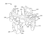
- FIGS. 3-7 illustrate another example of a fusion device that includes a plurality of blade anchors and a minimalistic body.
- the blade anchors may provide compression across a fusion or fracture line in any application where a typical bone staple could be used, such as in small bone osteosynthesis or sternal closure.
- Fusion device 200 may include at least two components, or staples, that are connected via a central mechanism, allowing fragments to be compressed towards a single point or axis. Fusion device 200 includes a first component 202 , and a second component 204 .
- the first component 202 includes a body 205 , a first arm 206 that terminates in a first blade 208 , and a second arm 210 that terminates in a second blade 212 , the second arm 210 opposite the first arm 206 .
- the first blade 208 may be oriented perpendicular to the length of the first arm 206 in two planes and the second blade 212 may be oriented perpendicular to the length of the second arm 210 in three planes, and the arms 206 , 210 may be mutually parallel and collinear.
- This orthogonal arrangement is one example of the contemplated range of all angles between the arms and blades.
- Other examples include blades whose tips diverge or converge, a blade forming an acute angle with an arm in one or more planes, or arms forming an included obtuse or acute angle between them in one or more planes.
- the length of the first arm 206 and the second arm 210 may be variable to accommodate different patient anatomies and different applications.
- the first and second arms 206 , 210 may have equal or unequal lengths.
- a set of first components having a range of arm lengths may be provided.
- the first component also includes a central portion 214 , located between the first arm 206 and the second arm 210 .
- the first and second arms 206 , 210 may be said to extend radially from the central portion 214 .
- the first and second arms 206 , 210 may have concave leading edges 230 and blunt trailing ends 232 . Together, the first and second arms 206 , 210 may be said to provide a biconcave leading edge.
- the central portion 214 may include a connecting feature 216 that extends outward from the body 203 .
- the connecting feature 216 may be a snap hook to prevent axial separation, a taper connection to prevent axial rotation and separation with a friction fit, a connecting feature that allows translation along the length of the first component 202 , or a cap or clip to maintain the connection.
- the connecting feature 216 includes prongs which extend longitudinally from the body 203 . Each prong may include a lip extending radially from the prongs, wherein each lip may provide a snap fit or other reversible fixation with the second component 204 .
- the first component shown in FIGS. 4-5 may be described as a male staple.
- the second component 204 also includes a body 217 , a first arm 218 that terminates in a third blade 220 , and a second arm 222 that terminates in a fourth blade 224 , the second arm 222 opposite the first arm 218 . While an orthogonal arrangement is shown, all other angular relationships between at least the arms and blades are contemplated.
- the second component 204 also includes a central portion 226 , located between the first arm 218 and the second arm 222 , which may be an aperture, receptacle, or socket shaped to receive the connecting feature 216 of the male connection staple.
- the first and second arms 218 , 222 may be said to extend radially from the central portion 226 .
- the first and second arms 218 , 222 may have concave leading edges 234 and blunt trailing ends 236 . Together, the first and second arms 206 , 210 may be said to provide a biconcave leading edge.
- the second component 204 shown in FIGS. 6-7 may be described as a female staple.
- the male connection staple 202 and the female connection staple 204 become joined or coupled together such that the first blade 210 , the second blade 212 , the third blade 220 and the fourth blade 222 may extend outward from the connected, aligned central portions 214 , 226 to engage the carpal bones such that the staples 202 , 204 may become axially fixed, rotationally fixed, or both.
- Each of the blades 208 , 212 , 220 , 224 may be angled or contain at least one angled surface to provide enhanced compression between opposing bones.
- a blade may be angled so that a tapered leading point of the blade is farther from the corresponding body than a trailing rear portion of the blade, so that as the blade penetrates the bone, the bone is urged toward the body. In an arrangement where every blade is so angled, each blade may urge a separate bone or bone fragment toward the body.
- Each of the blades 208 , 212 , 220 , 224 may also include additional fixation features 228 such as teeth, serrations, or barbs to enhance their interaction with the bones, such as to inhibit backward migration of the blade out of the bone after implantation.
- the connection between the female connection staple 204 and the male connection staple 202 may not constrain all degrees of freedom, as the carpal bones may provide sufficient rotational constraint once the fusion device is implanted.
- FIGS. 8 and 9 illustrate a fusion device 250 with at least two blades 254 , 256 , and no connecting feature.
- Fusion device, or staple 250 includes a central portion 252 and two lateral blades 254 , 256 .
- the central portion 252 may have a sharpened biconcave leading edge 253 and a blunt trailing end 255 .
- the blades may have features similar to those previously described, and may contain an exterior surface 258 that faces away from the central portion and an interior surface 260 opposite the exterior surface 258 .
- the interior surface 260 may be sloped and may intersect that exterior surface 258 at a tip portion 262 .
- the orthogonal arrangement shown is one example of the range of all angular relationships which are contemplated in the scope of this disclosure.
- a first compression staple may be placed proximal to and crossing a second compression staple.
- the slope of the interior surfaces 260 may create a wedge effect to create compression and achieve the desired orientation for fusion applications.
- Coupled is defined as connected, although not necessarily directly, and not necessarily mechanically.
- a step of a method or an element of a device that “comprises,” “has,” “includes” or “contains” one or more features, possesses those one or more features, but is not limited to possessing only those one or more features.
- a device or structure that is configured in a certain way is configured in at least that way, but may also be configured in ways that are not listed.
- the present invention may be embodied in other specific forms without departing from its spirit or essential characteristics. It is appreciated that various features of the above-described examples can be mixed and matched to form a variety of other alternatives. For example, a blade configuration from one or more fixation device examples may be found on the other fixation device examples disclosed herein. Similarly, manufacturing, assembly or implantation methods described for one fixation device or component may be used in the manufacture, assembly or implantation of the other fixation devices or components disclosed herein. As such, the described embodiments are to be considered in all respects only as illustrative and not restrictive. The scope of the invention is, therefore, indicated by the appended claims rather than by the foregoing description. All changes which come within the meaning and range of equivalency of the claims are to be embraced within their scope.
Abstract
Description
Claims (11)
Priority Applications (2)
| Application Number | Priority Date | Filing Date | Title |
|---|---|---|---|
| US13/666,787 US9254130B2 (en) | 2011-11-01 | 2012-11-01 | Blade anchor systems for bone fusion |
| US15/014,930 US10245090B2 (en) | 2011-11-01 | 2016-02-03 | Blade anchor systems for bone fusion |
Applications Claiming Priority (2)
| Application Number | Priority Date | Filing Date | Title |
|---|---|---|---|
| US201161554386P | 2011-11-01 | 2011-11-01 | |
| US13/666,787 US9254130B2 (en) | 2011-11-01 | 2012-11-01 | Blade anchor systems for bone fusion |
Related Child Applications (1)
| Application Number | Title | Priority Date | Filing Date |
|---|---|---|---|
| US15/014,930 Continuation US10245090B2 (en) | 2011-11-01 | 2016-02-03 | Blade anchor systems for bone fusion |
Publications (2)
| Publication Number | Publication Date |
|---|---|
| US20130123863A1 US20130123863A1 (en) | 2013-05-16 |
| US9254130B2 true US9254130B2 (en) | 2016-02-09 |
Family
ID=48281344
Family Applications (2)
| Application Number | Title | Priority Date | Filing Date |
|---|---|---|---|
| US13/666,787 Active 2033-04-28 US9254130B2 (en) | 2011-11-01 | 2012-11-01 | Blade anchor systems for bone fusion |
| US15/014,930 Active 2032-11-16 US10245090B2 (en) | 2011-11-01 | 2016-02-03 | Blade anchor systems for bone fusion |
Family Applications After (1)
| Application Number | Title | Priority Date | Filing Date |
|---|---|---|---|
| US15/014,930 Active 2032-11-16 US10245090B2 (en) | 2011-11-01 | 2016-02-03 | Blade anchor systems for bone fusion |
Country Status (1)
| Country | Link |
|---|---|
| US (2) | US9254130B2 (en) |
Cited By (19)
| Publication number | Priority date | Publication date | Assignee | Title |
|---|---|---|---|---|
| US9925051B2 (en) | 2010-12-16 | 2018-03-27 | Engage Medical Holdings, Llc | Arthroplasty systems and methods |
| US20180092748A1 (en) * | 2010-01-13 | 2018-04-05 | Jcbd, Llc | Sacroiliac joint implant system |
| US10034676B2 (en) | 2010-01-13 | 2018-07-31 | Jcbd, Llc | Systems for and methods of fusing a sacroiliac joint |
| US10064728B2 (en) | 2010-01-13 | 2018-09-04 | Jcbd, Llc | Methods of fusing a sacroiliac joint with a threaded joint fixation screw having a plurality of openings therein |
| US10238426B2 (en) | 2009-12-17 | 2019-03-26 | Engage Medical Holdings, Llc | Blade fixation for ankle fusion and arthroplasty |
| US10238382B2 (en) | 2012-03-26 | 2019-03-26 | Engage Medical Holdings, Llc | Blade anchor for foot and ankle |
| US10245090B2 (en) | 2011-11-01 | 2019-04-02 | Engage Medical Holdings, Llc | Blade anchor systems for bone fusion |
| US10245087B2 (en) | 2013-03-15 | 2019-04-02 | Jcbd, Llc | Systems and methods for fusing a sacroiliac joint and anchoring an orthopedic appliance |
| US10292720B2 (en) | 2010-01-13 | 2019-05-21 | Jcbd, Llc | Methods of fusing a sacroiliac joint |
| US10314710B2 (en) | 2010-01-13 | 2019-06-11 | Jcbd, Llc | Methods of fusing a sacroiliac joint |
| US10335197B2 (en) | 2012-07-20 | 2019-07-02 | Jcbd, Llc | Orthopedic anchoring methods |
| US10383664B2 (en) | 2013-07-30 | 2019-08-20 | Jcbd, Llc | Implants, systems, and methods for fusing a sacroiliac joint |
| US10390955B2 (en) | 2016-09-22 | 2019-08-27 | Engage Medical Holdings, Llc | Bone implants |
| US10441318B2 (en) | 2010-01-13 | 2019-10-15 | Jcbd, Llc | Additively manufactured systems for low profile spinopelvic fixation and sacroiliac joint fusion for complex spinal deformities |
| US10456272B2 (en) | 2017-03-03 | 2019-10-29 | Engage Uni Llc | Unicompartmental knee arthroplasty |
| US10492688B2 (en) | 2014-05-27 | 2019-12-03 | Jcbd, Llc | Systems for and methods of diagnosing and treating a sacroiliac joint disorder |
| US10492802B2 (en) | 2013-07-30 | 2019-12-03 | Jcbd, Llc | Systems for and methods of preparing a sacroiliac joint for fusion |
| US10603055B2 (en) | 2017-09-15 | 2020-03-31 | Jcbd, Llc | Systems for and methods of preparing and fusing a sacroiliac joint |
| US11540928B2 (en) | 2017-03-03 | 2023-01-03 | Engage Uni Llc | Unicompartmental knee arthroplasty |
Families Citing this family (16)
| Publication number | Priority date | Publication date | Assignee | Title |
|---|---|---|---|---|
| AU2014365821B2 (en) | 2013-12-20 | 2019-10-03 | Crossroads Extremity Systems, Llc | Polyaxial locking hole |
| US10299842B2 (en) | 2013-12-20 | 2019-05-28 | Crossroads Extremity Systems, Llc | Bone plates with dynamic elements |
| US11202626B2 (en) | 2014-07-10 | 2021-12-21 | Crossroads Extremity Systems, Llc | Bone implant with means for multi directional force and means of insertion |
| AU2015287901A1 (en) | 2014-07-10 | 2017-02-23 | Crossroads Extremity Systems, Llc | Bone implant and means of insertion |
| US20170000533A1 (en) * | 2015-07-02 | 2017-01-05 | First Ray, LLC | Compression implants, instruments and methods |
| US10357260B2 (en) | 2015-11-02 | 2019-07-23 | First Ray, LLC | Orthopedic fastener, retainer, and guide methods |
| US11864753B2 (en) | 2017-02-06 | 2024-01-09 | Crossroads Extremity Systems, Llc | Implant inserter |
| WO2018148284A1 (en) * | 2017-02-07 | 2018-08-16 | Crossroads Extremity Systems, Llc | Counter-torque implant |
| US11406502B2 (en) | 2017-03-02 | 2022-08-09 | Optimotion Implants LLC | Orthopedic implants and methods |
| US10905436B2 (en) | 2017-03-02 | 2021-02-02 | Optimotion Implants, Llc | Knee arthroplasty systems and methods |
| USD895113S1 (en) | 2018-08-08 | 2020-09-01 | Medshape, Inc. | Low profile staple |
| US11116499B1 (en) * | 2018-08-08 | 2021-09-14 | Medshape, Inc. | Low profile staple and methods for using the same |
| USD957636S1 (en) | 2018-08-08 | 2022-07-12 | Medshape, Inc. | Low profile staple |
| US10307156B1 (en) * | 2018-08-08 | 2019-06-04 | Medshape, Inc. | Low profile staple and methods for using same |
| USD961081S1 (en) | 2020-11-18 | 2022-08-16 | Crossroads Extremity Systems, Llc | Orthopedic implant |
| US20230181184A1 (en) * | 2021-12-10 | 2023-06-15 | Wright Medical Technology, Inc. | Stabilization devices |
Citations (263)
| Publication number | Priority date | Publication date | Assignee | Title |
|---|---|---|---|---|
| US3486505A (en) | 1967-05-22 | 1969-12-30 | Gordon M Morrison | Orthopedic surgical instrument |
| US3641590A (en) | 1970-01-16 | 1972-02-15 | Arthur A Michele | Acetabular replacement prosthesis and method of assembling |
| US3650309A (en) | 1969-02-12 | 1972-03-21 | Robert Neuschotz | Structure and use of fasteners having locking keys |
| US3842825A (en) | 1973-11-12 | 1974-10-22 | R Wagner | Hip fixation device |
| US3848276A (en) | 1973-05-03 | 1974-11-19 | Y Martinez | Knee implant device |
| US3882917A (en) | 1970-04-03 | 1975-05-13 | Litton Industrial Products | Self-locking thread |
| US3896504A (en) | 1972-10-14 | 1975-07-29 | Artur Fischer | Hip joint prosthesis |
| US3907017A (en) | 1974-09-30 | 1975-09-23 | Glenn W Stanwick | Interfering thread form |
| US3927503A (en) | 1973-12-26 | 1975-12-23 | Standard Pressed Steel Co | Prevailing torque fastener |
| US4011602A (en) | 1975-10-06 | 1977-03-15 | Battelle Memorial Institute | Porous expandable device for attachment to bone tissue |
| US4047524A (en) | 1975-04-28 | 1977-09-13 | Downs Surgical Limited | Surgical implant spinal staple |
| US4260005A (en) | 1977-11-09 | 1981-04-07 | Vsi Corporation | Self-locking fastener, fastener system, and process |
| US4349955A (en) | 1976-05-07 | 1982-09-21 | Taper Line, Inc. | Method of locking a male member to a female member |
| US4355429A (en) | 1979-01-26 | 1982-10-26 | Osteo Ag | Slide prosthesis for the knee joint |
| US4484570A (en) | 1980-05-28 | 1984-11-27 | Synthes Ltd. | Device comprising an implant and screws for fastening said implant to a bone, and a device for connecting two separated pieces of bone |
| US4501269A (en) | 1981-12-11 | 1985-02-26 | Washington State University Research Foundation, Inc. | Process for fusing bone joints |
| EP0179695A1 (en) | 1984-09-26 | 1986-04-30 | Pierre Kehr | Vertebral prosthesis, in particular for cervical vertebrae |
| US4611581A (en) | 1983-12-16 | 1986-09-16 | Acromed Corporation | Apparatus for straightening spinal columns |
| US4642869A (en) | 1984-02-07 | 1987-02-17 | Multifastener Corporation | Process of attaching a nut to a plate-shaped workpiece |
| US4681589A (en) | 1984-06-01 | 1987-07-21 | Tronzo Raymond G | Adjustable acetabular cup prosthesis as part of a total cup replacement system |
| US4716893A (en) | 1985-03-11 | 1988-01-05 | Artur Fischer | Bone fastener |
| US4743256A (en) | 1985-10-04 | 1988-05-10 | Brantigan John W | Surgical prosthetic implant facilitating vertebral interbody fusion and method |
| US4764067A (en) | 1985-11-22 | 1988-08-16 | Jsm Screw Co., Ltd. | Screw with groove for self-lock and method and rolling flat die for manufacturing the same |
| US4820305A (en) | 1986-11-03 | 1989-04-11 | Harms Juergen | Place holder, in particular for a vertebra body |
| US4834757A (en) | 1987-01-22 | 1989-05-30 | Brantigan John W | Prosthetic implant |
| US4838891A (en) | 1984-11-28 | 1989-06-13 | Branemark Per Ingvar | Joint prothesis |
| US4865607A (en) | 1985-10-02 | 1989-09-12 | Ulrich Witzel | Tibial plate for a knee-joint endoprosthesis |
| US4874389A (en) | 1987-12-07 | 1989-10-17 | Downey Ernest L | Replacement disc |
| US4930962A (en) | 1988-12-01 | 1990-06-05 | Pac-Fasteners, An Affiliate Of Peterson American Corp. | Nut and stud assembly |
| US4946378A (en) | 1987-11-24 | 1990-08-07 | Asahi Kogaku Kogyo Kabushiki Kaisha | Artificial intervertebral disc |
| US4957496A (en) | 1988-11-11 | 1990-09-18 | Mecron Medizinische Produkte Gmbh | Slotted slide plate assembly for osteosynthesis |
| US5002576A (en) | 1988-06-06 | 1991-03-26 | Mecron Medizinische Produkte Gmbh | Intervertebral disk endoprosthesis |
| US5019103A (en) | 1990-02-05 | 1991-05-28 | Boehringer Mannheim Corporation | Tibial wedge system |
| US5074880A (en) | 1988-12-20 | 1991-12-24 | S.P.O.R.T. | Anchoring device for knee prosthesis |
| US5147361A (en) | 1989-11-29 | 1992-09-15 | Asahi Kogaku Kogyo Kabushiki Kaisha | Vertebral connecting plate |
| US5163960A (en) | 1990-06-28 | 1992-11-17 | Bonutti Peter M | Surgical devices assembled using heat bondable materials |
| US5192327A (en) | 1991-03-22 | 1993-03-09 | Brantigan John W | Surgical prosthetic implant for vertebrae |
| US5192324A (en) | 1982-02-18 | 1993-03-09 | Howmedica Inc. | Bone prosthesis with porous coating |
| WO1993022990A1 (en) | 1992-05-18 | 1993-11-25 | Astra Aktiebolag | Joint prosthesis and apparatus for preparing the bone prior to fitting of the prosthesis |
| US5306309A (en) | 1992-05-04 | 1994-04-26 | Calcitek, Inc. | Spinal disk implant and implantation kit |
| US5314477A (en) | 1990-03-07 | 1994-05-24 | J.B.S. Limited Company | Prosthesis for intervertebral discs and instruments for implanting it |
| US5431658A (en) | 1994-02-14 | 1995-07-11 | Moskovich; Ronald | Facilitator for vertebrae grafts and prostheses |
| US5443515A (en) | 1994-01-26 | 1995-08-22 | Implex Corporation | Vertebral body prosthetic implant with slidably positionable stabilizing member |
| US5449359A (en) | 1991-09-05 | 1995-09-12 | Groiso; Jorge A. | Elastic clip for osteosynthesis |
| USD364462S (en) | 1994-03-28 | 1995-11-21 | Michelson Gary K | Spinal fixation staple |
| US5507816A (en) | 1991-12-04 | 1996-04-16 | Customflex Limited | Spinal vertebrae implants |
| US5514180A (en) | 1994-01-14 | 1996-05-07 | Heggeness; Michael H. | Prosthetic intervertebral devices |
| USD378409S (en) | 1995-10-30 | 1997-03-11 | Michelson Gary K | Spinal fixation staple |
| US5609635A (en) | 1988-06-28 | 1997-03-11 | Michelson; Gary K. | Lordotic interbody spinal fusion implants |
| US5658337A (en) | 1994-05-23 | 1997-08-19 | Spine-Tech, Inc. | Intervertebral fusion implant |
| US5683394A (en) | 1995-09-29 | 1997-11-04 | Advanced Spine Fixation Systems, Inc. | Fusion mass constrainer |
| US5702449A (en) | 1995-06-07 | 1997-12-30 | Danek Medical, Inc. | Reinforced porous spinal implants |
| US5709683A (en) | 1995-12-19 | 1998-01-20 | Spine-Tech, Inc. | Interbody bone implant having conjoining stabilization features for bony fusion |
| US5713899A (en) | 1995-04-27 | 1998-02-03 | Societe Jbs Sa | Cervical cage designed for the performance of intersomatic arthrodesis |
| US5769852A (en) | 1993-04-27 | 1998-06-23 | Medevelop Ab | Implantable anchoring element and anchoring assembly for prostheses |
| US5772661A (en) | 1988-06-13 | 1998-06-30 | Michelson; Gary Karlin | Methods and instrumentation for the surgical correction of human thoracic and lumbar spinal disease from the antero-lateral aspect of the spine |
| US5776199A (en) | 1988-06-28 | 1998-07-07 | Sofamor Danek Properties | Artificial spinal fusion implants |
| US5776202A (en) | 1993-09-07 | 1998-07-07 | Copf; Franz | Joint prosthesis |
| US5788701A (en) | 1995-12-21 | 1998-08-04 | Johnson & Johnson Professional, Inc. | Instrument system for knee prothesis implantation with universal handle or slap hammer |
| US5800550A (en) | 1996-03-13 | 1998-09-01 | Sertich; Mario M. | Interbody fusion cage |
| US5860973A (en) | 1995-02-27 | 1999-01-19 | Michelson; Gary Karlin | Translateral spinal implant |
| US5893890A (en) | 1994-03-18 | 1999-04-13 | Perumala Corporation | Rotating, locking intervertebral disk stabilizer and applicator |
| US5893889A (en) | 1997-06-20 | 1999-04-13 | Harrington; Michael | Artificial disc |
| US5947999A (en) | 1996-12-03 | 1999-09-07 | Groiso; Jorge A. | Surgical clip and method |
| US6039762A (en) | 1995-06-07 | 2000-03-21 | Sdgi Holdings, Inc. | Reinforced bone graft substitutes |
| US6063121A (en) | 1998-07-29 | 2000-05-16 | Xavier; Ravi | Vertebral body prosthesis |
| US6080155A (en) | 1988-06-13 | 2000-06-27 | Michelson; Gary Karlin | Method of inserting and preloading spinal implants |
| US6096080A (en) | 1998-05-06 | 2000-08-01 | Cortek, Inc. | Apparatus for spinal fusion using implanted devices |
| US6102949A (en) | 1997-12-03 | 2000-08-15 | Biedermann Motech Gmbh | Intervertebrae implant |
| US6113638A (en) | 1999-02-26 | 2000-09-05 | Williams; Lytton A. | Method and apparatus for intervertebral implant anchorage |
| US6120503A (en) | 1994-03-28 | 2000-09-19 | Michelson; Gary Karlin | Apparatus instrumentation, and method for spinal fixation |
| WO2000025707A9 (en) | 1998-10-30 | 2000-11-02 | Gary K Michelson | Self-broaching, rotatable, push-in interbody fusion implant and method for deployment thereof |
| US6159214A (en) | 1996-07-31 | 2000-12-12 | Michelson; Gary K. | Milling instrumentation and method for preparing a space between adjacent vertebral bodies |
| WO2000064360A9 (en) | 1999-04-23 | 2001-04-26 | Sdgi Holdings Inc | Method for the correction of spinal deformities through vertebral body tethering without fusion |
| US6224607B1 (en) | 1999-01-25 | 2001-05-01 | Gary K. Michelson | Instrumentation and method for creating an intervertebral space for receiving an implant |
| US6235059B1 (en) | 1996-04-03 | 2001-05-22 | Scient'x (Societe A Responsabilite Limitee) | Intersomatic setting and fusion system |
| US6241770B1 (en) | 1999-03-05 | 2001-06-05 | Gary K. Michelson | Interbody spinal fusion implant having an anatomically conformed trailing end |
| US6309421B1 (en) | 1994-03-18 | 2001-10-30 | Madhavan Pisharodi | Rotating, locking intervertebral disk stabilizer and applicator |
| US20010037154A1 (en) | 2000-04-10 | 2001-11-01 | Martin Christopher Harris | Modular radial head prostheses |
| US20010047208A1 (en) | 1999-12-08 | 2001-11-29 | Michelson Gary K. | Spinal implant surface configuration |
| US6325805B1 (en) | 1999-04-23 | 2001-12-04 | Sdgi Holdings, Inc. | Shape memory alloy staple |
| US6336928B1 (en) | 1996-10-18 | 2002-01-08 | Depuy France | Device for securing at least two vertebrae |
| US20020004683A1 (en) | 2000-07-10 | 2002-01-10 | Michelson Gary K. | Flanged interbody spinal fusion implants |
| US20020035400A1 (en) | 2000-08-08 | 2002-03-21 | Vincent Bryan | Implantable joint prosthesis |
| US20020049447A1 (en) | 2000-08-29 | 2002-04-25 | Li Medical Technologies, Inc. | Expandable surgical fastener and method |
| US6402785B1 (en) | 1999-06-04 | 2002-06-11 | Sdgi Holdings, Inc. | Artificial disc implant |
| US6413278B1 (en) | 1998-03-30 | 2002-07-02 | J. Alexander Marchosky | Prosthetic system |
| US20020099376A1 (en) | 2001-01-23 | 2002-07-25 | Michelson Gary K. | Interbody spinal implant with trailing end adapted to receive bone screws |
| US6432107B1 (en) | 2000-01-15 | 2002-08-13 | Bret A. Ferree | Enhanced surface area spinal fusion devices |
| US6436098B1 (en) | 1993-06-10 | 2002-08-20 | Sofamor Danek Holdings, Inc. | Method for inserting spinal implants and for securing a guard to the spine |
| US20020116165A1 (en) | 2001-02-13 | 2002-08-22 | El-Ghoroury Hussein S. | Matched instruction set processor systems and method, system, and apparatus to efficiently design and implement matched instruction set processor systems by mapping system designs to re-configurable hardware platforms |
| US20020116065A1 (en) | 1998-10-21 | 2002-08-22 | Jackson Roger P. | Spinal fusion apparatus and method |
| US6447524B1 (en) | 2000-10-19 | 2002-09-10 | Ethicon Endo-Surgery, Inc. | Fastener for hernia mesh fixation |
| US6447546B1 (en) | 2000-08-11 | 2002-09-10 | Dale G. Bramlet | Apparatus and method for fusing opposing spinal vertebrae |
| US6458159B1 (en) | 2000-08-15 | 2002-10-01 | John S. Thalgott | Disc prosthesis |
| US20020147454A1 (en) | 2001-04-10 | 2002-10-10 | Neto Aziz Rassi | Building configuration introduced in a surgical-use screw |
| US20020147499A1 (en) | 2001-02-26 | 2002-10-10 | Shea Jeffrey J. | Locking systems for implants |
| US20020161443A1 (en) | 2001-04-02 | 2002-10-31 | Michelson Gary K. | Artificial contoured spinal fusion implants made of a material other than bone |
| US20020165613A1 (en) | 2001-05-04 | 2002-11-07 | Chih-I Lin | Intervertebral fixation device having one or more bracing elements |
| US6478800B1 (en) | 2000-05-08 | 2002-11-12 | Depuy Acromed, Inc. | Medical installation tool |
| US6485517B1 (en) | 1999-05-05 | 2002-11-26 | Gary K. Michelson | Nested interbody spinal fusion implants |
| US6506216B1 (en) | 1998-05-13 | 2003-01-14 | Depuy Products, Inc. | Tibial tray with adjustable keel |
| US20030045940A1 (en) | 2001-08-24 | 2003-03-06 | Robert Eberlein | Artificial intervertebral disc |
| US20030060884A1 (en) | 1999-05-10 | 2003-03-27 | Fell Barry M. | Surgically implantable knee prosthesis having keels |
| US6558424B2 (en) | 2001-06-28 | 2003-05-06 | Depuy Acromed | Modular anatomic fusion device |
| US6558423B1 (en) | 1999-05-05 | 2003-05-06 | Gary K. Michelson | Interbody spinal fusion implants with multi-lock for locking opposed screws |
| WO2003005939A3 (en) | 2001-07-13 | 2003-05-22 | Ldr Medical | Vertebral cage device with modular fixation |
| US20030100949A1 (en) | 2000-04-19 | 2003-05-29 | Michelson Gary K. | Expandable threaded arcuate interbody spinal fusion implant with cylindrical configuration during insertion |
| US6582468B1 (en) | 1998-12-11 | 2003-06-24 | Spryker Spine | Intervertebral disc prosthesis with compressible body |
| US20030120344A1 (en) | 2001-04-02 | 2003-06-26 | Michelson Gary K. | Contoured spinal fusion implants made of bone or a bone composite material |
| WO2003053290A1 (en) | 2001-12-12 | 2003-07-03 | Vita Special Purpose Corporation | Bioactive spinal implants and method of manufacture thereof |
| US6599294B2 (en) | 1999-01-30 | 2003-07-29 | Aesculap Ag & Co. Kg | Surgical instrument for introducing intervertebral implants |
| US20030158553A1 (en) | 1988-06-13 | 2003-08-21 | Michelson Gary Karlin | Instrumentation for the surgical correction of spinal disease |
| US6610093B1 (en) | 2000-07-28 | 2003-08-26 | Perumala Corporation | Method and apparatus for stabilizing adjacent vertebrae |
| US6620198B2 (en) | 1999-10-07 | 2003-09-16 | Exactech, Inc. | Composite bearing inserts for total knee joints |
| WO2001003570A3 (en) | 1999-07-07 | 2003-10-09 | M D Eric J Wall | Spinal correction system |
| US20030195632A1 (en) | 2001-02-06 | 2003-10-16 | Foley Kevin T. | Spinal implant with attached ligament |
| WO2003039400A3 (en) | 2001-11-06 | 2003-10-23 | Ldr Medical | Osseous anchoring device for a prosthesis |
| US6652533B2 (en) | 2001-09-20 | 2003-11-25 | Depuy Acromed, Inc. | Medical inserter tool with slaphammer |
| WO2003065930A3 (en) | 2002-02-02 | 2003-12-11 | Gary K Michelson | Spinal fusion implant having deployable bone engaging projections |
| US20040030336A1 (en) | 2002-08-06 | 2004-02-12 | Khanna Rohit Kumar | Anterior cervical spine stabilization method and system |
| US20040030339A1 (en) | 2001-04-20 | 2004-02-12 | Wack Michael A. | Dual locking plate and associated method |
| US6716245B2 (en) | 2000-07-12 | 2004-04-06 | Spine Next | Intersomatic implant |
| US20040073315A1 (en) | 2002-04-25 | 2004-04-15 | Justin Daniel F. | Modular bone implant, tools, and method |
| US6726720B2 (en) | 2002-03-27 | 2004-04-27 | Depuy Spine, Inc. | Modular disc prosthesis |
| US20040083005A1 (en) | 1998-12-22 | 2004-04-29 | Magnus Jacobsson | Method of anchoring a prosthesis structure |
| WO2003092507A3 (en) | 2002-05-06 | 2004-05-06 | Sdgi Holdings Inc | Instrumentation and methods for preparation of an intervertebral space |
| US6740118B2 (en) | 2002-01-09 | 2004-05-25 | Sdgi Holdings, Inc. | Intervertebral prosthetic joint |
| US6743256B2 (en) | 2000-10-11 | 2004-06-01 | Michael D. Mason | Graftless spinal fusion device |
| US20040133203A1 (en) | 2002-10-28 | 2004-07-08 | Young J Stewart | Multi-axial, cross-link connector system for spinal implants |
| US20040148028A1 (en) | 2002-12-19 | 2004-07-29 | Ferree Bret A. | Artificial disc replacement (ADR) extraction methods and apparatus |
| US6770096B2 (en) | 1999-07-01 | 2004-08-03 | Spinevision S.A. | Interbody spinal stabilization cage and spinal stabilization method |
| US6770074B2 (en) | 1988-06-13 | 2004-08-03 | Gary Karlin Michelson | Apparatus for use in inserting spinal implants |
| WO2004071359A1 (en) | 2003-02-12 | 2004-08-26 | Sdgi Holdings Inc. | Articular disc prosthesis for lateral insertion |
| US20040176853A1 (en) | 2003-03-05 | 2004-09-09 | Sennett Andrew R. | Apparatus and method for spinal fusion using posteriorly implanted devices |
| US20040193271A1 (en) | 2003-03-31 | 2004-09-30 | Depuy Acromed | Method and apparatus for implant stability |
| US6800093B2 (en) | 1998-05-06 | 2004-10-05 | Cortek, Inc. | Device for spinal fusion |
| US6802863B2 (en) | 2002-03-13 | 2004-10-12 | Cross Medical Products, Inc. | Keeled prosthetic nucleus |
| US20040225295A1 (en) | 2001-07-16 | 2004-11-11 | Rafail Zubok | Wedge ramp distractor and related methods for use in implanting artificial intervertebral discs |
| US20040254581A1 (en) | 2003-02-04 | 2004-12-16 | Leclair Walter J. | Furcated bone screw |
| US20040254644A1 (en) | 2002-10-21 | 2004-12-16 | Taylor Brett Allison | Intervertebral disk prosthesis |
| US20040260286A1 (en) | 1999-10-08 | 2004-12-23 | Ferree Bret A. | Intradiscal devices with anti-extrusion keels |
| US6835208B2 (en) | 1998-03-30 | 2004-12-28 | J. Alexander Marchosky | Prosthetic system |
| US20050004672A1 (en) | 1995-10-16 | 2005-01-06 | John Pafford | Bone grafts |
| US20050014919A1 (en) | 2001-06-15 | 2005-01-20 | Hyoe Hatakeyama | Lignin-based polyurethane and process for producing the same |
| US6849093B2 (en) | 2001-03-09 | 2005-02-01 | Gary K. Michelson | Expansion constraining member adapted for use with an expandable interbody spinal fusion implant and method for use thereof |
| US20050027300A1 (en) | 2003-03-31 | 2005-02-03 | Depuy Spine, Inc. | Method and apparatus for artificial disc insertion |
| US20050049600A1 (en) | 2003-08-05 | 2005-03-03 | Groiso Jorge A. | Osteosynthesis clip and insertion tool for inserting an osteosynthesis clip into bone tissue fragments |
| US20050055031A1 (en) | 2003-09-10 | 2005-03-10 | Roy Lim | Devices and methods for inserting spinal implants |
| WO2005051243A2 (en) | 2003-10-30 | 2005-06-09 | Steven Streatfield Gill | An intervertebral prosthesis |
| US20050125065A1 (en) | 2003-11-05 | 2005-06-09 | St. Francis Medical Technologies Inc. | Laterally insertable artificial vertebral disk replacement implant with crossbar spacer |
| US20050131545A1 (en) | 2003-12-10 | 2005-06-16 | Alan Chervitz | Spinal facet implant with spherical implant apposition surface and bone bed and methods of use |
| US20050149192A1 (en) | 2003-11-20 | 2005-07-07 | St. Francis Medical Technologies, Inc. | Intervertebral body fusion cage with keels and implantation method |
| US20050149193A1 (en) | 2003-11-20 | 2005-07-07 | St. Francis Medical Technology, Inc. | Intervertebral body fusion cage with keels and implantation methods |
| US20050165408A1 (en) | 2004-01-26 | 2005-07-28 | Puno Rolando M. | Methods and instrumentation for inserting intervertebral grafts and devices |
| US6923810B1 (en) | 1988-06-13 | 2005-08-02 | Gary Karlin Michelson | Frusto-conical interbody spinal fusion implants |
| US20050171607A1 (en) | 2000-06-13 | 2005-08-04 | Michelson Gary K. | Manufactured bone composite implant shaped to conform to a prepared implantation space |
| US6926718B1 (en) | 1997-02-11 | 2005-08-09 | Gary K. Michelson | Multilock anterior cervical plating system |
| US20050177239A1 (en) | 1995-09-04 | 2005-08-11 | Amiram Steinberg | Method and apparatus for computerized surgery |
| WO2005074841A1 (en) | 2004-01-30 | 2005-08-18 | Sdgi Holdings, Inc. | Anatomic implants designed to minimize instruments and surgical techniques |
| US20050192586A1 (en) | 2002-10-29 | 2005-09-01 | St. Francis Medical Technologies, Inc. | Method of preparing for an artificial intervertebral implant using tool |
| US20060004453A1 (en) | 2004-06-30 | 2006-01-05 | Depuy Spine, Inc. | Ceramic disc prosthesis |
| WO2004108015A3 (en) | 2003-06-06 | 2006-01-19 | Bret A Ferree | Artificial disc replacements with oblique keels |
| US6989031B2 (en) | 2001-04-02 | 2006-01-24 | Sdgi Holdings, Inc. | Hemi-interbody spinal implant manufactured from a major long bone ring or a bone composite |
| EP1327423B1 (en) | 2002-01-11 | 2006-03-29 | Zimmer GmbH | A surgically implantable knee prosthesis having keels |
| US20060074421A1 (en) | 2003-05-08 | 2006-04-06 | Bickley Barry T | Fixation augmentation device and related techniques |
| US20060085071A1 (en) | 2003-02-06 | 2006-04-20 | Beat Lechmann | Intervertebral implant |
| US20060095136A1 (en) | 2004-11-03 | 2006-05-04 | Mcluen Design, Inc. | Bone fusion device |
| US7044972B2 (en) | 2001-01-30 | 2006-05-16 | Synthes Ag Chur | Bone implant, in particular, an inter-vertebral implant |
| WO2006051547A2 (en) | 2004-11-15 | 2006-05-18 | Disc-O-Tech Medical Technologies, Ltd. | Assembled prosthesis such as a disc |
| US20060111787A1 (en) | 2004-11-05 | 2006-05-25 | Bailie David S | Glenoid prosthesis and method of implanting same |
| US20060116769A1 (en) | 2004-11-26 | 2006-06-01 | Theirry Marnay | Intervertebral implant |
| US7056345B2 (en) | 2000-12-15 | 2006-06-06 | Spineology, Inc. | Annulus-reinforcing band |
| US20060129238A1 (en) | 2004-10-26 | 2006-06-15 | Adam Paltzer | Spinal stabilization device and methods |
| US20060136063A1 (en) | 2004-12-22 | 2006-06-22 | Ldr Medical | Intervertebral disc prosthesis |
| US20060136061A1 (en) | 2003-04-04 | 2006-06-22 | Theken Disc, Llc | Artificial disc prosthesis |
| WO2006074414A2 (en) | 2005-01-08 | 2006-07-13 | Alphaspine, Inc. | Modular disc device |
| US7087082B2 (en) | 1998-08-03 | 2006-08-08 | Synthes (Usa) | Bone implants with central chambers |
| US20060178745A1 (en) | 2005-02-10 | 2006-08-10 | Depuy Spine, Inc. | Intervertebral prosthetic disc |
| US20060195097A1 (en) | 2005-02-25 | 2006-08-31 | Evans David E | Implant insertion apparatus and method of use |
| US7115146B2 (en) | 2000-03-22 | 2006-10-03 | Boyer Ii Michael L | Multipiece implants formed of bone material |
| US7118580B1 (en) | 1999-09-14 | 2006-10-10 | Spine Solutions Inc. | Instrument for inserting intervertebral implants |
| US20060241641A1 (en) | 2005-04-22 | 2006-10-26 | Sdgi Holdings, Inc. | Methods and instrumentation for distraction and insertion of implants in a spinal disc space |
| US7128761B2 (en) | 2003-12-10 | 2006-10-31 | Axiomed Spine Corporation | Method and apparatus for replacing a damaged spinal disc |
| US20070010890A1 (en) | 2005-07-08 | 2007-01-11 | Howmedica Osteonics Corp. | Modular tibial baseplate |
| US7166110B2 (en) | 2004-01-09 | 2007-01-23 | Yundt Kent D | Method, system and apparatus for interbody fusion |
| US7169182B2 (en) | 2001-07-16 | 2007-01-30 | Spinecore, Inc. | Implanting an artificial intervertebral disc |
| US20070050032A1 (en) | 2005-09-01 | 2007-03-01 | Spinal Kinetics, Inc. | Prosthetic intervertebral discs |
| WO2007034310A1 (en) | 2005-09-23 | 2007-03-29 | Ldr Medical | Intervertebral disc prosthesis |
| US7204852B2 (en) | 2002-12-13 | 2007-04-17 | Spine Solutions, Inc. | Intervertebral implant, insertion tool and method of inserting same |
| US20070093839A1 (en) | 2005-09-12 | 2007-04-26 | Beckendorf Brandon G | Compression staple |
| US20070118132A1 (en) | 2002-07-19 | 2007-05-24 | Triage Medical, Inc. | Method and apparatus for spinal fixation |
| US20070118145A1 (en) | 2005-11-24 | 2007-05-24 | Kay Fischer | Surgical guiding instrument |
| US20070123903A1 (en) | 2005-10-31 | 2007-05-31 | Depuy Spine, Inc. | Medical Device installation tool and methods of use |
| US20070142922A1 (en) | 2005-12-21 | 2007-06-21 | Lewis Paul P P | Modular hip cup assembly, fastener assembly & fastener |
| US7235105B2 (en) | 2003-09-18 | 2007-06-26 | Jackson Roger P | Threaded center line cage with winged end gap |
| US7235101B2 (en) | 2003-09-15 | 2007-06-26 | Warsaw Orthopedic, Inc. | Revisable prosthetic device |
| WO2007028098A3 (en) | 2005-09-01 | 2007-06-28 | Spinal Kinetics Inc | Prosthetic intervertebral discs |
| WO2007087366A2 (en) | 2006-01-25 | 2007-08-02 | Spinemedica Corporation | Spinal disc implants with flexible keels and methods of fabricating implants |
| US20070185375A1 (en) | 2006-02-06 | 2007-08-09 | Depuy Spine, Inc. | Medical device installation tool |
| US20070191850A1 (en) | 2004-08-27 | 2007-08-16 | Depuy Spine, Inc. | Vertebral staples and insertion tools |
| US20070233244A1 (en) * | 2006-03-28 | 2007-10-04 | Depuy Spine, Inc. | Artificial Disc Replacement Using Posterior Approach |
| US20070239278A1 (en) | 2006-04-06 | 2007-10-11 | Sdgi Holdings, Inc. | Intervertebral prosthetic devices and methods |
| US20070288021A1 (en) | 2006-06-07 | 2007-12-13 | Howmedica Osteonics Corp. | Flexible joint implant |
| US20070288005A1 (en) | 2006-04-05 | 2007-12-13 | Uri Arnin | Fixation of spinal prosthesis |
| US20070299529A1 (en) | 2006-06-22 | 2007-12-27 | Depuy Products, Inc. | Tibial insert having multiple keels |
| US20080015702A1 (en) | 2006-07-11 | 2008-01-17 | Ebi, L.P. | Intervertebral implantation apparatus |
| WO2008014258A2 (en) | 2006-07-24 | 2008-01-31 | Spine Solutions, Inc. | Intervertebral implant with keel |
| WO2008014453A2 (en) | 2006-07-28 | 2008-01-31 | Spinalmotion, Inc. | Spinal prosthesis with multiple pillar anchors |
| WO2008021955A2 (en) | 2006-08-10 | 2008-02-21 | James Dwyer | Modular intervertebral disc prosthesis and method of replacing an intervertebral disc |
| EP1897517A1 (en) | 2006-09-07 | 2008-03-12 | Biomet Manufacturing Corp. | Method and apparatus for wrist anthroplasty |
| US7357817B2 (en) | 2005-05-19 | 2008-04-15 | Howmedica Osteonics Corp. | Modular keel tibial component |
| US20080103598A1 (en) | 2006-09-15 | 2008-05-01 | Trudeau Jeffrey L | System and Method for Sizing, Inserting and Securing Artificial Disc in Intervertebral Space |
| US20080132949A1 (en) | 2005-12-29 | 2008-06-05 | Joseph Aferzon | Apparatus and method for anterior intervertebral spinal fixation and fusion |
| US20080147203A1 (en) | 2006-12-15 | 2008-06-19 | Zimmer Technology, Inc. | Modular plate and keel provisionals |
| US20080154377A1 (en) | 2006-12-22 | 2008-06-26 | Voellmicke John C | Composite vertebral spacers and instrument |
| US20080167721A1 (en) | 2006-12-22 | 2008-07-10 | Qi-Bin Bao | Implant retention device and method |
| US20080177275A1 (en) | 2006-12-01 | 2008-07-24 | Charles Wing | Interbody distractor |
| US20080208345A1 (en) | 2005-10-27 | 2008-08-28 | Kinetic Spine Technologies, Inc. | Intervertebral implant |
| US20080249575A1 (en) | 2007-04-03 | 2008-10-09 | Warsaw Orthopedic, Inc. | Anchor Member Locking Features |
| WO2008128367A1 (en) | 2007-04-20 | 2008-10-30 | Woodwelding Ag | Method for fastening an implant to bone tissue and corresponding implant system |
| US20080269764A1 (en) | 2007-04-25 | 2008-10-30 | Spinal Elements, Inc. | Spinal implant distractor/inserter |
| US20080275455A1 (en) | 2006-08-16 | 2008-11-06 | Amicus, Llc | Apparatus and Methods for Inserting an Implant |
| US20080287957A1 (en) | 2007-05-18 | 2008-11-20 | Depuy Spine, Inc. | Insertion blade assembly and method of use |
| US20090005870A1 (en) | 2007-06-26 | 2009-01-01 | John Riley Hawkins | Highly Lordosed Fusion Cage |
| US20090005784A1 (en) | 2007-04-25 | 2009-01-01 | Spinal Elements, Inc. | Spinal implant distractor/inserter |
| US20090048604A1 (en) | 2007-08-13 | 2009-02-19 | Stryker Spine | Insertion instrument for intervertebral implants |
| US7503935B2 (en) | 2003-12-02 | 2009-03-17 | Kyphon Sarl | Method of laterally inserting an artificial vertebral disk replacement with translating pivot point |
| US20090088849A1 (en) | 2007-09-27 | 2009-04-02 | Warsaw Orthopedic, Inc. | Intervertebral Implant |
| US20090099601A1 (en) | 2007-10-11 | 2009-04-16 | International Spinal Innovations, Llc | Minimally invasive lateral intervertbral fixation system, device and method |
| US20090099602A1 (en) | 2007-09-11 | 2009-04-16 | Kamran Aflatoon | Method of lateral facet approach, decompression and fusion using screws and staples as well as arthroplasty |
| WO2009070721A1 (en) | 2007-11-28 | 2009-06-04 | Pioneer Surgical Technology, Inc | Device for securing an implant to tissue |
| USD594986S1 (en) | 2005-03-29 | 2009-06-23 | Nuvasive, Inc. | Intervertebral implant |
| US7556650B2 (en) | 2004-06-29 | 2009-07-07 | Spine Wave, Inc. | Methods for injecting a curable biomaterial into an intervertebral space |
| US7572293B2 (en) | 2005-06-30 | 2009-08-11 | Depuy Products, Inc. | Tibial insert and associated surgical method |
| US20090240333A1 (en) | 2007-09-17 | 2009-09-24 | Trudeau Jeffrey L | Motion Preserving Artificial Intervertebral Disc Device |
| US7611538B2 (en) | 2003-08-04 | 2009-11-03 | Zimmer Spine S.A.S. | Intervertebral disk prosthesis |
| US20100004747A1 (en) | 2008-07-07 | 2010-01-07 | Jin-Fu Lin | Trans-Vertebral and Intra-Vertebral Plate and Fusion Cage Device for Spinal Interbody Fusion and Method of Operation |
| US7658766B2 (en) | 2006-05-01 | 2010-02-09 | Warsaw Orthopedic, Inc. | Intervertebral implants with covered inner chamber and methods of use |
| US20100069958A1 (en) * | 2008-09-18 | 2010-03-18 | Smith & Nephew, Inc. | Tenodesis Implant |
| WO2010039026A1 (en) | 2008-09-30 | 2010-04-08 | J. Van Straten Beheer B.V. | Ankle prosthesis and a tibial component therefor |
| US20100185287A1 (en) | 2009-01-21 | 2010-07-22 | Warsaw Orthopedic, Inc. | Spinal nucleus replacement implants |
| US20100185292A1 (en) | 2009-01-22 | 2010-07-22 | Stephen Hochschuler | Apparatus and method for stabilizing adjacent bone portions |
| US20100204739A1 (en) | 2009-02-11 | 2010-08-12 | IMDS, Inc. | Intervertebral implant with integrated fixation |
| US20100201739A1 (en) | 2009-02-12 | 2010-08-12 | Sony Corporation | Liquid ejection apparatus |
| WO2010121002A1 (en) | 2009-04-15 | 2010-10-21 | Synthes Usa, Llc | Vertebral implant system for a flexible interbody spacer |
| US7909871B2 (en) | 2005-10-03 | 2011-03-22 | Samy Abdou | Devices and methods for inter-vertebral orthopedic device placement |
| US7918891B1 (en) | 2004-03-29 | 2011-04-05 | Nuvasive Inc. | Systems and methods for spinal fusion |
| WO2011044879A1 (en) | 2009-10-12 | 2011-04-21 | Aap Implantate Ag | Modular system for anchoring and positioning components of implants |
| US20110160866A1 (en) | 2008-09-02 | 2011-06-30 | Synthes Usa, Llc | Intervertebral implant with blades for connecting to adjacent vertebral bodies |
| US20110166608A1 (en) | 2009-07-14 | 2011-07-07 | Neil Duggal | Joint Arthrodesis and Arthroplasty |
| WO2011090508A1 (en) | 2010-01-22 | 2011-07-28 | Stephen Hochschuler | Apparatus and method for stabilizing adjacent bone portions |
| US8034076B2 (en) | 2000-10-23 | 2011-10-11 | Tyco Healthcare Group Lp | Absorbable fastener and applying apparatus |
| US8100974B2 (en) | 2004-06-30 | 2012-01-24 | Synergy Disc Replacement, Inc. | Artificial spinal disc |
| US8105389B2 (en) | 2002-10-24 | 2012-01-31 | Biomet Manufacturing Corp. | Method and apparatus for wrist arthroplasty |
| US8123757B2 (en) | 2003-12-31 | 2012-02-28 | Depuy Spine, Inc. | Inserter instrument and implant clip |
| US8133283B2 (en) | 2007-06-06 | 2012-03-13 | Kenneth Mitchell Wilson | Scapho-lunate fixation implants and methods of use |
| US20120215315A1 (en) | 2010-01-22 | 2012-08-23 | Stephen Hochschuler | Apparatus and method for stabilizing adjacent bone portions |
| US20120253406A1 (en) | 2009-11-03 | 2012-10-04 | Howmedica Osteonics Corp. | Intervertebral implant with integrated fixation |
| US20120265259A1 (en) | 2011-04-15 | 2012-10-18 | Laposta Marie | Fixation assembly |
| US20130013006A1 (en) | 2005-11-30 | 2013-01-10 | Ralph Rashbaum | Intervertebral disc prosthesis and instrumentation for insertion of the prosthesis between the vertebrae |
| US8491598B2 (en) | 2008-03-03 | 2013-07-23 | Us Spine, Inc. | Surgical positioning assembly and associated spinal implant device and surgical methods |
| US8500747B2 (en) | 2006-09-19 | 2013-08-06 | Warsaw Orthopedic, Inc. | Instruments and methods for spinal implant revision |
Family Cites Families (33)
| Publication number | Priority date | Publication date | Assignee | Title |
|---|---|---|---|---|
| US4454875A (en) | 1982-04-15 | 1984-06-19 | Techmedica, Inc. | Osteal medical staple |
| US4570623A (en) | 1983-06-02 | 1986-02-18 | Pfizer Hospital Products Group Inc. | Arched bridge staple |
| USD281814S (en) | 1983-07-13 | 1985-12-17 | Techmedica, Inc. | Osteotomy staple |
| US4848328A (en) | 1986-05-20 | 1989-07-18 | Laboureau Jacques P | Agraffe for osteosynthesis |
| US5053038A (en) | 1989-08-17 | 1991-10-01 | Tenstaple, Inc. | Compression bone staple |
| US5289963A (en) | 1991-10-18 | 1994-03-01 | United States Surgical Corporation | Apparatus and method for applying surgical staples to attach an object to body tissue |
| FR2695027B1 (en) | 1992-09-02 | 1994-10-28 | Georges Comte | Surgical clip and apparatus for its impaction. |
| US5352229A (en) | 1993-05-12 | 1994-10-04 | Marlowe Goble E | Arbor press staple and washer and method for its use |
| US6767356B2 (en) | 2000-09-01 | 2004-07-27 | Angiolink Corporation | Advanced wound site management systems and methods |
| US6623510B2 (en) | 2000-12-07 | 2003-09-23 | Integrated Vascular Systems, Inc. | Closure device and methods for making and using them |
| IES20010547A2 (en) | 2001-06-07 | 2002-12-11 | Christy Cummins | Surgical Staple |
| US7192447B2 (en) | 2002-12-19 | 2007-03-20 | Synthes (Usa) | Intervertebral implant |
| ES2279231T3 (en) | 2003-05-09 | 2007-08-16 | Tyco Healthcare Group Lp | ANASTOMOTIC STAPLE WITH CAPILLARY TUBE THAT DISPENSES FLUIDS. |
| WO2005007038A1 (en) | 2003-07-22 | 2005-01-27 | Synthes Gmbh | Articulated endoprosthesis |
| US7481832B1 (en) | 2003-09-09 | 2009-01-27 | Biomet Sports Medicine, Llc | Method and apparatus for use of a self-tapping resorbable screw |
| DE102004002946A1 (en) | 2004-01-21 | 2005-08-11 | Forschungszentrum Jülich GmbH | Protective layer for an aluminum-containing alloy for use at high temperatures, and method for producing such a protective layer |
| US7531002B2 (en) | 2004-04-16 | 2009-05-12 | Depuy Spine, Inc. | Intervertebral disc with monitoring and adjusting capabilities |
| US6942698B1 (en) | 2004-04-23 | 2005-09-13 | Roger P. Jackson | Spinal fusion interbody spacer |
| FR2874809B1 (en) | 2004-09-06 | 2008-02-01 | Newdeal Sa Sa | IMPLANT FOR FIXING A BONE GRAFT WITHIN A JOINT TO ENSURE THE ARTHRODESIS OF THE JOINT |
| CA2607921C (en) | 2005-05-11 | 2013-07-16 | Children's Hospital Medical Center | Spinal correction system |
| US20110160766A1 (en) | 2005-11-02 | 2011-06-30 | Hendren Ronald D | Medical Affixation Device |
| US8414616B2 (en) | 2006-09-12 | 2013-04-09 | Pioneer Surgical Technology, Inc. | Mounting devices for fixation devices and insertion instruments used therewith |
| US8485412B2 (en) | 2006-09-29 | 2013-07-16 | Ethicon Endo-Surgery, Inc. | Surgical staples having attached drivers and stapling instruments for deploying the same |
| USD574956S1 (en) | 2007-06-28 | 2008-08-12 | Biomedical Enterprises, Inc. | Soft tissue staple |
| US8142508B1 (en) | 2007-07-02 | 2012-03-27 | Theken Spine, Llc | Spinal cage having deployable member which is removable |
| US8808294B2 (en) | 2008-09-09 | 2014-08-19 | William Casey Fox | Method and apparatus for a multiple transition temperature implant |
| US9700434B2 (en) | 2009-08-10 | 2017-07-11 | Howmedica Osteonics Corp. | Intervertebral implant with integrated fixation |
| US9480511B2 (en) | 2009-12-17 | 2016-11-01 | Engage Medical Holdings, Llc | Blade fixation for ankle fusion and arthroplasty |
| WO2012083205A1 (en) | 2010-12-16 | 2012-06-21 | Medicinelodge, Inc. Dba Imds Co-Innovation | Arthroplasty systems and methods |
| WO2012112598A1 (en) | 2011-02-14 | 2012-08-23 | Imds Corporation | System and method for bone anchor removal |
| US9254130B2 (en) | 2011-11-01 | 2016-02-09 | Hyun Bae | Blade anchor systems for bone fusion |
| US20140039632A1 (en) | 2012-01-23 | 2014-02-06 | Imds Corporation | Glenoid vault fixation system |
| US10238382B2 (en) | 2012-03-26 | 2019-03-26 | Engage Medical Holdings, Llc | Blade anchor for foot and ankle |
-
2012
- 2012-11-01 US US13/666,787 patent/US9254130B2/en active Active
-
2016
- 2016-02-03 US US15/014,930 patent/US10245090B2/en active Active
Patent Citations (391)
| Publication number | Priority date | Publication date | Assignee | Title |
|---|---|---|---|---|
| US3486505A (en) | 1967-05-22 | 1969-12-30 | Gordon M Morrison | Orthopedic surgical instrument |
| US3650309A (en) | 1969-02-12 | 1972-03-21 | Robert Neuschotz | Structure and use of fasteners having locking keys |
| US3641590A (en) | 1970-01-16 | 1972-02-15 | Arthur A Michele | Acetabular replacement prosthesis and method of assembling |
| US3882917A (en) | 1970-04-03 | 1975-05-13 | Litton Industrial Products | Self-locking thread |
| US3896504A (en) | 1972-10-14 | 1975-07-29 | Artur Fischer | Hip joint prosthesis |
| US3848276A (en) | 1973-05-03 | 1974-11-19 | Y Martinez | Knee implant device |
| US3842825A (en) | 1973-11-12 | 1974-10-22 | R Wagner | Hip fixation device |
| US3927503A (en) | 1973-12-26 | 1975-12-23 | Standard Pressed Steel Co | Prevailing torque fastener |
| US3907017A (en) | 1974-09-30 | 1975-09-23 | Glenn W Stanwick | Interfering thread form |
| US4047524A (en) | 1975-04-28 | 1977-09-13 | Downs Surgical Limited | Surgical implant spinal staple |
| US4011602A (en) | 1975-10-06 | 1977-03-15 | Battelle Memorial Institute | Porous expandable device for attachment to bone tissue |
| US4349955A (en) | 1976-05-07 | 1982-09-21 | Taper Line, Inc. | Method of locking a male member to a female member |
| US4260005B1 (en) | 1977-11-09 | 1992-09-22 | Vsi Corp | |
| US4260005A (en) | 1977-11-09 | 1981-04-07 | Vsi Corporation | Self-locking fastener, fastener system, and process |
| US4355429A (en) | 1979-01-26 | 1982-10-26 | Osteo Ag | Slide prosthesis for the knee joint |
| US4484570A (en) | 1980-05-28 | 1984-11-27 | Synthes Ltd. | Device comprising an implant and screws for fastening said implant to a bone, and a device for connecting two separated pieces of bone |
| US4501269A (en) | 1981-12-11 | 1985-02-26 | Washington State University Research Foundation, Inc. | Process for fusing bone joints |
| US5192324A (en) | 1982-02-18 | 1993-03-09 | Howmedica Inc. | Bone prosthesis with porous coating |
| US4611581A (en) | 1983-12-16 | 1986-09-16 | Acromed Corporation | Apparatus for straightening spinal columns |
| US4642869A (en) | 1984-02-07 | 1987-02-17 | Multifastener Corporation | Process of attaching a nut to a plate-shaped workpiece |
| US4681589A (en) | 1984-06-01 | 1987-07-21 | Tronzo Raymond G | Adjustable acetabular cup prosthesis as part of a total cup replacement system |
| US4743262A (en) | 1984-06-01 | 1988-05-10 | Tronzo Raymond G | Acetabular cup prosthesis |
| US4743262B1 (en) | 1984-06-01 | 1994-05-17 | Raymond G Tronzo | Acetabular cup prosthesis |
| EP0179695A1 (en) | 1984-09-26 | 1986-04-30 | Pierre Kehr | Vertebral prosthesis, in particular for cervical vertebrae |
| US4838891A (en) | 1984-11-28 | 1989-06-13 | Branemark Per Ingvar | Joint prothesis |
| US4716893A (en) | 1985-03-11 | 1988-01-05 | Artur Fischer | Bone fastener |
| US4865607A (en) | 1985-10-02 | 1989-09-12 | Ulrich Witzel | Tibial plate for a knee-joint endoprosthesis |
| US4743256A (en) | 1985-10-04 | 1988-05-10 | Brantigan John W | Surgical prosthetic implant facilitating vertebral interbody fusion and method |
| US4764067A (en) | 1985-11-22 | 1988-08-16 | Jsm Screw Co., Ltd. | Screw with groove for self-lock and method and rolling flat die for manufacturing the same |
| US4820305A (en) | 1986-11-03 | 1989-04-11 | Harms Juergen | Place holder, in particular for a vertebra body |
| US4834757A (en) | 1987-01-22 | 1989-05-30 | Brantigan John W | Prosthetic implant |
| US4946378A (en) | 1987-11-24 | 1990-08-07 | Asahi Kogaku Kogyo Kabushiki Kaisha | Artificial intervertebral disc |
| US4874389A (en) | 1987-12-07 | 1989-10-17 | Downey Ernest L | Replacement disc |
| US5002576A (en) | 1988-06-06 | 1991-03-26 | Mecron Medizinische Produkte Gmbh | Intervertebral disk endoprosthesis |
| US20030158553A1 (en) | 1988-06-13 | 2003-08-21 | Michelson Gary Karlin | Instrumentation for the surgical correction of spinal disease |
| US6080155A (en) | 1988-06-13 | 2000-06-27 | Michelson; Gary Karlin | Method of inserting and preloading spinal implants |
| US6270498B1 (en) | 1988-06-13 | 2001-08-07 | Gary Karlin Michelson | Apparatus for inserting spinal implants |
| US6923810B1 (en) | 1988-06-13 | 2005-08-02 | Gary Karlin Michelson | Frusto-conical interbody spinal fusion implants |
| US5772661A (en) | 1988-06-13 | 1998-06-30 | Michelson; Gary Karlin | Methods and instrumentation for the surgical correction of human thoracic and lumbar spinal disease from the antero-lateral aspect of the spine |
| US7491205B1 (en) | 1988-06-13 | 2009-02-17 | Warsaw Orthopedic, Inc. | Instrumentation for the surgical correction of human thoracic and lumbar spinal disease from the lateral aspect of the spine |
| US6770074B2 (en) | 1988-06-13 | 2004-08-03 | Gary Karlin Michelson | Apparatus for use in inserting spinal implants |
| US5609635A (en) | 1988-06-28 | 1997-03-11 | Michelson; Gary K. | Lordotic interbody spinal fusion implants |
| US5776199A (en) | 1988-06-28 | 1998-07-07 | Sofamor Danek Properties | Artificial spinal fusion implants |
| US7066961B2 (en) | 1988-06-28 | 2006-06-27 | Gary Karlin Michelson | Spinal implant |
| US4957496A (en) | 1988-11-11 | 1990-09-18 | Mecron Medizinische Produkte Gmbh | Slotted slide plate assembly for osteosynthesis |
| US4930962A (en) | 1988-12-01 | 1990-06-05 | Pac-Fasteners, An Affiliate Of Peterson American Corp. | Nut and stud assembly |
| US5074880A (en) | 1988-12-20 | 1991-12-24 | S.P.O.R.T. | Anchoring device for knee prosthesis |
| US5147361A (en) | 1989-11-29 | 1992-09-15 | Asahi Kogaku Kogyo Kabushiki Kaisha | Vertebral connecting plate |
| US5019103A (en) | 1990-02-05 | 1991-05-28 | Boehringer Mannheim Corporation | Tibial wedge system |
| US5314477A (en) | 1990-03-07 | 1994-05-24 | J.B.S. Limited Company | Prosthesis for intervertebral discs and instruments for implanting it |
| US5163960A (en) | 1990-06-28 | 1992-11-17 | Bonutti Peter M | Surgical devices assembled using heat bondable materials |
| US5192327A (en) | 1991-03-22 | 1993-03-09 | Brantigan John W | Surgical prosthetic implant for vertebrae |
| US5660188A (en) | 1991-05-09 | 1997-08-26 | Groiso; Jorge A. | Procedure for applying an elastic clip |
| US5853414A (en) | 1991-05-09 | 1998-12-29 | Groiso; Jorge A. | Elastic clip for osteosynthesis |
| US5449359A (en) | 1991-09-05 | 1995-09-12 | Groiso; Jorge A. | Elastic clip for osteosynthesis |
| US5507816A (en) | 1991-12-04 | 1996-04-16 | Customflex Limited | Spinal vertebrae implants |
| US5306309A (en) | 1992-05-04 | 1994-04-26 | Calcitek, Inc. | Spinal disk implant and implantation kit |
| WO1993022990A1 (en) | 1992-05-18 | 1993-11-25 | Astra Aktiebolag | Joint prosthesis and apparatus for preparing the bone prior to fitting of the prosthesis |
| US5769852A (en) | 1993-04-27 | 1998-06-23 | Medevelop Ab | Implantable anchoring element and anchoring assembly for prostheses |
| US6436098B1 (en) | 1993-06-10 | 2002-08-20 | Sofamor Danek Holdings, Inc. | Method for inserting spinal implants and for securing a guard to the spine |
| US6875213B2 (en) | 1993-06-10 | 2005-04-05 | Sdgi Holdings, Inc. | Method of inserting spinal implants with the use of imaging |
| US5776202A (en) | 1993-09-07 | 1998-07-07 | Copf; Franz | Joint prosthesis |
| US5514180A (en) | 1994-01-14 | 1996-05-07 | Heggeness; Michael H. | Prosthetic intervertebral devices |
| US5443515A (en) | 1994-01-26 | 1995-08-22 | Implex Corporation | Vertebral body prosthetic implant with slidably positionable stabilizing member |
| US5431658A (en) | 1994-02-14 | 1995-07-11 | Moskovich; Ronald | Facilitator for vertebrae grafts and prostheses |
| US5893890A (en) | 1994-03-18 | 1999-04-13 | Perumala Corporation | Rotating, locking intervertebral disk stabilizer and applicator |
| US6309421B1 (en) | 1994-03-18 | 2001-10-30 | Madhavan Pisharodi | Rotating, locking intervertebral disk stabilizer and applicator |
| US20020095155A1 (en) | 1994-03-28 | 2002-07-18 | Michelson Gary Karlin | Spinal implant containing bone morphogenetic protein |
| US7255698B2 (en) | 1994-03-28 | 2007-08-14 | Warsaw Orthopedic, Inc. | Apparatus and method for anterior spinal stabilization |
| USD364462S (en) | 1994-03-28 | 1995-11-21 | Michelson Gary K | Spinal fixation staple |
| US6364880B1 (en) | 1994-03-28 | 2002-04-02 | Gary Karlin Michelson | Spinal implant with bone screws |
| US20020099378A1 (en) | 1994-03-28 | 2002-07-25 | Michelson Gary Karlin | Apparatus, instrumentation and method for spinal fixation |
| US20040034353A1 (en) | 1994-03-28 | 2004-02-19 | Michelson Gary Karlin | Apparatus and method for anterior spinal stabilization |
| US6120503A (en) | 1994-03-28 | 2000-09-19 | Michelson; Gary Karlin | Apparatus instrumentation, and method for spinal fixation |
| US6136001A (en) | 1994-03-28 | 2000-10-24 | Michelson; Gary Karlin | Apparatus and method for linking spinal implants |
| US5658337A (en) | 1994-05-23 | 1997-08-19 | Spine-Tech, Inc. | Intervertebral fusion implant |
| US5860973A (en) | 1995-02-27 | 1999-01-19 | Michelson; Gary Karlin | Translateral spinal implant |
| US20020091390A1 (en) | 1995-02-27 | 2002-07-11 | Michelson Gary Karlin | Methods and instrumentation for the surgical correction of human thoracic and lumbar spinal disease from the lateral aspect of the spine |
| US5713899A (en) | 1995-04-27 | 1998-02-03 | Societe Jbs Sa | Cervical cage designed for the performance of intersomatic arthrodesis |
| US5702449A (en) | 1995-06-07 | 1997-12-30 | Danek Medical, Inc. | Reinforced porous spinal implants |
| US20050038512A1 (en) | 1995-06-07 | 2005-02-17 | Michelson Gary Karlin | Implant having arcuate upper and lower bearing surfaces along a longitudinal axis |
| US20030040798A1 (en) | 1995-06-07 | 2003-02-27 | Michelson Gary Karlin | Lordotic interbody spinal fusion implants |
| US7503933B2 (en) | 1995-06-07 | 2009-03-17 | Warsaw Orthopedic, Inc. | Lordotic interbody spinal fusion implants |
| US6039762A (en) | 1995-06-07 | 2000-03-21 | Sdgi Holdings, Inc. | Reinforced bone graft substitutes |
| US6302914B1 (en) | 1995-06-07 | 2001-10-16 | Gary Karlin Michelson | Lordotic interbody spinal fusion implants |
| US6447544B1 (en) | 1995-06-07 | 2002-09-10 | Gary Karlin Michelson | Lordotic interbody spinal fusion implants |
| US20050177239A1 (en) | 1995-09-04 | 2005-08-11 | Amiram Steinberg | Method and apparatus for computerized surgery |
| US5683394A (en) | 1995-09-29 | 1997-11-04 | Advanced Spine Fixation Systems, Inc. | Fusion mass constrainer |
| US20050004672A1 (en) | 1995-10-16 | 2005-01-06 | John Pafford | Bone grafts |
| USD378409S (en) | 1995-10-30 | 1997-03-11 | Michelson Gary K | Spinal fixation staple |
| US5885287A (en) | 1995-12-19 | 1999-03-23 | Spine-Tech, Inc. | Self-tapping interbody bone implant |
| US5709683A (en) | 1995-12-19 | 1998-01-20 | Spine-Tech, Inc. | Interbody bone implant having conjoining stabilization features for bony fusion |
| US5788701A (en) | 1995-12-21 | 1998-08-04 | Johnson & Johnson Professional, Inc. | Instrument system for knee prothesis implantation with universal handle or slap hammer |
| US5800550A (en) | 1996-03-13 | 1998-09-01 | Sertich; Mario M. | Interbody fusion cage |
| US6235059B1 (en) | 1996-04-03 | 2001-05-22 | Scient'x (Societe A Responsabilite Limitee) | Intersomatic setting and fusion system |
| US7083623B2 (en) | 1996-07-31 | 2006-08-01 | Sdgi Holdings, Inc. | Milling instrumentation and method for preparing a space between adjacent vertebral bodies |
| US20040249388A1 (en) | 1996-07-31 | 2004-12-09 | Michelson Gary K. | Distractor with opening |
| US20040215203A1 (en) | 1996-07-31 | 2004-10-28 | Michelson Gary K. | Bone removal device |
| US20010000532A1 (en) | 1996-07-31 | 2001-04-26 | Michelson Gary K. | Milling instrumentation and method for preparing a space between adjacent vertebral bodies |
| US6159214A (en) | 1996-07-31 | 2000-12-12 | Michelson; Gary K. | Milling instrumentation and method for preparing a space between adjacent vertebral bodies |
| US20020091392A1 (en) | 1996-07-31 | 2002-07-11 | Michelson Gary K. | Milling instrumentation and method for preparing a space between adjacent vertebral bodies |
| US6336928B1 (en) | 1996-10-18 | 2002-01-08 | Depuy France | Device for securing at least two vertebrae |
| US5947999A (en) | 1996-12-03 | 1999-09-07 | Groiso; Jorge A. | Surgical clip and method |
| US5993476A (en) | 1996-12-03 | 1999-11-30 | Groiso; Jorge A. | Surgical clip and method |
| US6926718B1 (en) | 1997-02-11 | 2005-08-09 | Gary K. Michelson | Multilock anterior cervical plating system |
| US6969390B2 (en) | 1997-02-11 | 2005-11-29 | Michelson Gary K | Anterior cervical plating system and bone screw |
| US5893889A (en) | 1997-06-20 | 1999-04-13 | Harrington; Michael | Artificial disc |
| US6102949A (en) | 1997-12-03 | 2000-08-15 | Biedermann Motech Gmbh | Intervertebrae implant |
| US6835208B2 (en) | 1998-03-30 | 2004-12-28 | J. Alexander Marchosky | Prosthetic system |
| US6413278B1 (en) | 1998-03-30 | 2002-07-02 | J. Alexander Marchosky | Prosthetic system |
| US6096080A (en) | 1998-05-06 | 2000-08-01 | Cortek, Inc. | Apparatus for spinal fusion using implanted devices |
| US6679887B2 (en) | 1998-05-06 | 2004-01-20 | Cortek, Inc. | Surgical procedure for implanting spinal fusion device |
| US6241769B1 (en) | 1998-05-06 | 2001-06-05 | Cortek, Inc. | Implant for spinal fusion |
| US6800093B2 (en) | 1998-05-06 | 2004-10-05 | Cortek, Inc. | Device for spinal fusion |
| US6506216B1 (en) | 1998-05-13 | 2003-01-14 | Depuy Products, Inc. | Tibial tray with adjustable keel |
| US7083652B2 (en) | 1998-05-13 | 2006-08-01 | Depuy Products, Inc. | Tibial tray with adjustable keel |
| US6063121A (en) | 1998-07-29 | 2000-05-16 | Xavier; Ravi | Vertebral body prosthesis |
| US7087082B2 (en) | 1998-08-03 | 2006-08-08 | Synthes (Usa) | Bone implants with central chambers |
| US20020116065A1 (en) | 1998-10-21 | 2002-08-22 | Jackson Roger P. | Spinal fusion apparatus and method |
| US20010047207A1 (en) | 1998-10-30 | 2001-11-29 | Michelson Gary K. | Self-broaching, rotatable, push-in interbody spinal fusion implant and method for deployment thereof |
| WO2000025707A9 (en) | 1998-10-30 | 2000-11-02 | Gary K Michelson | Self-broaching, rotatable, push-in interbody fusion implant and method for deployment thereof |
| US20030149483A1 (en) | 1998-10-30 | 2003-08-07 | Michelson Gary K. | Self-broaching, rotatable, push-in interbody spinal fusion implant and method for deployment thereof |
| US7396365B2 (en) | 1998-10-30 | 2008-07-08 | Warsaw Orthopedic, Inc. | Method for inserting a fusion cage having a height substantially the same as the height between adjacent vertebral endplates |
| US20050216083A1 (en) | 1998-10-30 | 2005-09-29 | Michelson Gary K | Method for inserting a fusion cage having a height substantially the same as the height between adjacent vertebral endplates |
| US6537320B1 (en) | 1998-10-30 | 2003-03-25 | Gary K. Michelson | Self-broaching, rotatable, push-in interbody spinal fusion implant and method for deployment thereof |
| US6582468B1 (en) | 1998-12-11 | 2003-06-24 | Spryker Spine | Intervertebral disc prosthesis with compressible body |
| US20040083005A1 (en) | 1998-12-22 | 2004-04-29 | Magnus Jacobsson | Method of anchoring a prosthesis structure |
| US20030195517A1 (en) | 1999-01-25 | 2003-10-16 | Michelson Gary K. | Instrumentation for creating an intervertebral space for receiving an implant |
| US6224607B1 (en) | 1999-01-25 | 2001-05-01 | Gary K. Michelson | Instrumentation and method for creating an intervertebral space for receiving an implant |
| US20010010001A1 (en) | 1999-01-25 | 2001-07-26 | Michelson Gary K. | Instrumentation and method for creating an intervertebral space for receiving an implant |
| US20010010002A1 (en) | 1999-01-25 | 2001-07-26 | Michelson Gary K. | Instrumentation and method for creating an intervertebral space for receiving an implant |
| US6599294B2 (en) | 1999-01-30 | 2003-07-29 | Aesculap Ag & Co. Kg | Surgical instrument for introducing intervertebral implants |
| US6113638A (en) | 1999-02-26 | 2000-09-05 | Williams; Lytton A. | Method and apparatus for intervertebral implant anchorage |
| US20010010020A1 (en) | 1999-03-05 | 2001-07-26 | Michelson Gary K. | Interbody spinal fusion implant having an anatomically conformed trailing end |
| US20050216089A1 (en) | 1999-03-05 | 2005-09-29 | Michelson Gary K | Arcuate interbody spinal fusion implant having a reduced width and an anatomically conformed trailing end |
| US6241770B1 (en) | 1999-03-05 | 2001-06-05 | Gary K. Michelson | Interbody spinal fusion implant having an anatomically conformed trailing end |
| US20040064185A1 (en) | 1999-03-05 | 2004-04-01 | Michelson Gary K. | Interbody spinal fusion implant having a reduced width and an anatomically conformed trailing end |
| WO2000064360A9 (en) | 1999-04-23 | 2001-04-26 | Sdgi Holdings Inc | Method for the correction of spinal deformities through vertebral body tethering without fusion |
| US6773437B2 (en) | 1999-04-23 | 2004-08-10 | Sdgi Holdings, Inc. | Shape memory alloy staple |
| US6325805B1 (en) | 1999-04-23 | 2001-12-04 | Sdgi Holdings, Inc. | Shape memory alloy staple |
| US6485517B1 (en) | 1999-05-05 | 2002-11-26 | Gary K. Michelson | Nested interbody spinal fusion implants |
| US20040210313A1 (en) | 1999-05-05 | 2004-10-21 | Michelson Gary K. | Method for inserting nested interbody spinal fusion implants |
| US20030023307A1 (en) | 1999-05-05 | 2003-01-30 | Michelson Gary K. | Nested interbody spinal fusion implants |
| US6558423B1 (en) | 1999-05-05 | 2003-05-06 | Gary K. Michelson | Interbody spinal fusion implants with multi-lock for locking opposed screws |
| US7041135B2 (en) | 1999-05-05 | 2006-05-09 | Sdgi Holdings, Inc. | Interbody spinal fusion implants with single-lock for locking opposed screws |
| US7033394B2 (en) | 1999-05-05 | 2006-04-25 | Sdgi Holdings, Inc. | Interbody spinal fusion implants with end cap for locking vertebral body penetrating members |
| US20050038513A1 (en) | 1999-05-05 | 2005-02-17 | Michelson Gary K. | Apparatus for inserting nested interbody spinal fusion implants |
| US20030060884A1 (en) | 1999-05-10 | 2003-03-27 | Fell Barry M. | Surgically implantable knee prosthesis having keels |
| US6402785B1 (en) | 1999-06-04 | 2002-06-11 | Sdgi Holdings, Inc. | Artificial disc implant |
| US6770096B2 (en) | 1999-07-01 | 2004-08-03 | Spinevision S.A. | Interbody spinal stabilization cage and spinal stabilization method |
| US8021403B2 (en) | 1999-07-07 | 2011-09-20 | Children's Hospital Medical Center | Spinal staple system |
| US7481830B2 (en) | 1999-07-07 | 2009-01-27 | Children's Hospital Medical Center | Spinal correction system |
| WO2001003570A3 (en) | 1999-07-07 | 2003-10-09 | M D Eric J Wall | Spinal correction system |
| US20050277933A1 (en) | 1999-07-07 | 2005-12-15 | Wall Eric J | Spinal correction system |
| US6746450B1 (en) | 1999-07-07 | 2004-06-08 | Children's Hospital Medical Center | Spinal correction system |
| US7118580B1 (en) | 1999-09-14 | 2006-10-10 | Spine Solutions Inc. | Instrument for inserting intervertebral implants |
| US6620198B2 (en) | 1999-10-07 | 2003-09-16 | Exactech, Inc. | Composite bearing inserts for total knee joints |
| US20040260286A1 (en) | 1999-10-08 | 2004-12-23 | Ferree Bret A. | Intradiscal devices with anti-extrusion keels |
| US20020013624A1 (en) | 1999-12-08 | 2002-01-31 | Michelson Gary K. | Spinal implant surface configuration |
| US7166129B2 (en) | 1999-12-08 | 2007-01-23 | Warsaw Orthopedic, Inc. | Method for forming a spinal implant surface configuration |
| US6827740B1 (en) | 1999-12-08 | 2004-12-07 | Gary K. Michelson | Spinal implant surface configuration |
| US20040117018A1 (en) | 1999-12-08 | 2004-06-17 | Michelson Gary K. | Spinal implant surface configuration with a projection having a back cut |
| US20010047208A1 (en) | 1999-12-08 | 2001-11-29 | Michelson Gary K. | Spinal implant surface configuration |
| US6432107B1 (en) | 2000-01-15 | 2002-08-13 | Bret A. Ferree | Enhanced surface area spinal fusion devices |
| US7115146B2 (en) | 2000-03-22 | 2006-10-03 | Boyer Ii Michael L | Multipiece implants formed of bone material |
| US20010037154A1 (en) | 2000-04-10 | 2001-11-01 | Martin Christopher Harris | Modular radial head prostheses |
| US6972035B2 (en) | 2000-04-19 | 2005-12-06 | Michelson Gary K | Expandable threaded arcuate interbody spinal fusion implant with cylindrical configuration during insertion |
| US20030100949A1 (en) | 2000-04-19 | 2003-05-29 | Michelson Gary K. | Expandable threaded arcuate interbody spinal fusion implant with cylindrical configuration during insertion |
| US6478800B1 (en) | 2000-05-08 | 2002-11-12 | Depuy Acromed, Inc. | Medical installation tool |
| US6755841B2 (en) | 2000-05-08 | 2004-06-29 | Depuy Acromed, Inc. | Medical installation tool |
| US20050171606A1 (en) | 2000-06-13 | 2005-08-04 | Michelson Gary K. | Method for installation of manufactured implants shaped to conform to a prepared implantation space |
| US20050171607A1 (en) | 2000-06-13 | 2005-08-04 | Michelson Gary K. | Manufactured bone composite implant shaped to conform to a prepared implantation space |
| US20040210314A1 (en) | 2000-07-10 | 2004-10-21 | Michelson Gary K. | Flanged interbody spinal fusion implants |
| US20020004683A1 (en) | 2000-07-10 | 2002-01-10 | Michelson Gary K. | Flanged interbody spinal fusion implants |
| US20070106388A1 (en) | 2000-07-10 | 2007-05-10 | Sdgi Holdings, Inc. | Flanged interbody spinal fusion implants |
| WO2002003885A3 (en) | 2000-07-10 | 2002-06-20 | Gary K Michelson | Flanged interbody spinal fusion implants |
| US6716245B2 (en) | 2000-07-12 | 2004-04-06 | Spine Next | Intersomatic implant |
| US6610093B1 (en) | 2000-07-28 | 2003-08-26 | Perumala Corporation | Method and apparatus for stabilizing adjacent vertebrae |
| US20020035400A1 (en) | 2000-08-08 | 2002-03-21 | Vincent Bryan | Implantable joint prosthesis |
| US6447546B1 (en) | 2000-08-11 | 2002-09-10 | Dale G. Bramlet | Apparatus and method for fusing opposing spinal vertebrae |
| US6458159B1 (en) | 2000-08-15 | 2002-10-01 | John S. Thalgott | Disc prosthesis |
| US20020049447A1 (en) | 2000-08-29 | 2002-04-25 | Li Medical Technologies, Inc. | Expandable surgical fastener and method |
| US7163560B2 (en) | 2000-10-11 | 2007-01-16 | Mason Michael D | Method for graftless spinal fusion |
| US6743256B2 (en) | 2000-10-11 | 2004-06-01 | Michael D. Mason | Graftless spinal fusion device |
| US6447524B1 (en) | 2000-10-19 | 2002-09-10 | Ethicon Endo-Surgery, Inc. | Fastener for hernia mesh fixation |
| US8034076B2 (en) | 2000-10-23 | 2011-10-11 | Tyco Healthcare Group Lp | Absorbable fastener and applying apparatus |
| US7056345B2 (en) | 2000-12-15 | 2006-06-06 | Spineology, Inc. | Annulus-reinforcing band |
| US20060079961A1 (en) | 2001-01-23 | 2006-04-13 | Michelson Gary K | Implant with trailing end adapted to receive bone screws |
| US20090062921A1 (en) | 2001-01-23 | 2009-03-05 | Michelson Gary K | Implant with openings adapted to receive bone screws |
| WO2002058593A3 (en) | 2001-01-23 | 2003-03-06 | Gary K Michelson | Interbody spinal fusion implant with trailing end adapted to receive bone screws |
| US20020099376A1 (en) | 2001-01-23 | 2002-07-25 | Michelson Gary K. | Interbody spinal implant with trailing end adapted to receive bone screws |
| US7044972B2 (en) | 2001-01-30 | 2006-05-16 | Synthes Ag Chur | Bone implant, in particular, an inter-vertebral implant |
| US20030195632A1 (en) | 2001-02-06 | 2003-10-16 | Foley Kevin T. | Spinal implant with attached ligament |
| US20020116165A1 (en) | 2001-02-13 | 2002-08-22 | El-Ghoroury Hussein S. | Matched instruction set processor systems and method, system, and apparatus to efficiently design and implement matched instruction set processor systems by mapping system designs to re-configurable hardware platforms |
| US20020147499A1 (en) | 2001-02-26 | 2002-10-10 | Shea Jeffrey J. | Locking systems for implants |
| US7326248B2 (en) | 2001-03-09 | 2008-02-05 | Warsaw Orthopedic, Inc. | Expandable interbody spinal fusion implant with expansion constraining member and method for use thereof |
| US6849093B2 (en) | 2001-03-09 | 2005-02-01 | Gary K. Michelson | Expansion constraining member adapted for use with an expandable interbody spinal fusion implant and method for use thereof |
| US20060122702A1 (en) | 2001-04-02 | 2006-06-08 | Michelson Gary K | Hemi-interbody spinal fusion implants manufactured from a major long bone ring |
| US20040230308A1 (en) | 2001-04-02 | 2004-11-18 | Michelson Gary K. | Contoured cortical bone implants |
| US7540882B2 (en) | 2001-04-02 | 2009-06-02 | Warsaw Orthopedic, Inc. | Artificial spinal fusion implant with asymmetrical leading end |
| US20030120344A1 (en) | 2001-04-02 | 2003-06-26 | Michelson Gary K. | Contoured spinal fusion implants made of bone or a bone composite material |
| US20050187628A1 (en) | 2001-04-02 | 2005-08-25 | Michelson Gary K. | Artificial spinal fusion implant with asymmetrical leading end |
| US20050187629A1 (en) | 2001-04-02 | 2005-08-25 | Michelson Gary K. | Hemi-artificial contoured spinal fusion implants made of a material other than bone |
| US20020161443A1 (en) | 2001-04-02 | 2002-10-31 | Michelson Gary K. | Artificial contoured spinal fusion implants made of a material other than bone |
| US6989031B2 (en) | 2001-04-02 | 2006-01-24 | Sdgi Holdings, Inc. | Hemi-interbody spinal implant manufactured from a major long bone ring or a bone composite |
| US20020147454A1 (en) | 2001-04-10 | 2002-10-10 | Neto Aziz Rassi | Building configuration introduced in a surgical-use screw |
| US20040030339A1 (en) | 2001-04-20 | 2004-02-12 | Wack Michael A. | Dual locking plate and associated method |
| US20020165613A1 (en) | 2001-05-04 | 2002-11-07 | Chih-I Lin | Intervertebral fixation device having one or more bracing elements |
| US20050014919A1 (en) | 2001-06-15 | 2005-01-20 | Hyoe Hatakeyama | Lignin-based polyurethane and process for producing the same |
| US6558424B2 (en) | 2001-06-28 | 2003-05-06 | Depuy Acromed | Modular anatomic fusion device |
| US7594931B2 (en) | 2001-07-13 | 2009-09-29 | Ldr Medical | Vertebral cage device with modular fixation |
| WO2003005939A3 (en) | 2001-07-13 | 2003-05-22 | Ldr Medical | Vertebral cage device with modular fixation |
| US20040199254A1 (en) | 2001-07-13 | 2004-10-07 | Christian Louis | Vertebral cage device with modular fixation |
| US20040225295A1 (en) | 2001-07-16 | 2004-11-11 | Rafail Zubok | Wedge ramp distractor and related methods for use in implanting artificial intervertebral discs |
| US7169182B2 (en) | 2001-07-16 | 2007-01-30 | Spinecore, Inc. | Implanting an artificial intervertebral disc |
| US20050143747A1 (en) | 2001-07-16 | 2005-06-30 | Rafail Zubok | Parallel distractor and related methods for use in implanting an artificial intervertebral disc |
| US20030045940A1 (en) | 2001-08-24 | 2003-03-06 | Robert Eberlein | Artificial intervertebral disc |
| US6652533B2 (en) | 2001-09-20 | 2003-11-25 | Depuy Acromed, Inc. | Medical inserter tool with slaphammer |
| WO2003039400A3 (en) | 2001-11-06 | 2003-10-23 | Ldr Medical | Osseous anchoring device for a prosthesis |
| US7056344B2 (en) | 2001-11-06 | 2006-06-06 | Ldr Medical | Osseous anchoring device for a prosthesis |
| WO2003053290A1 (en) | 2001-12-12 | 2003-07-03 | Vita Special Purpose Corporation | Bioactive spinal implants and method of manufacture thereof |
| US6740118B2 (en) | 2002-01-09 | 2004-05-25 | Sdgi Holdings, Inc. | Intervertebral prosthetic joint |
| EP1327423B1 (en) | 2002-01-11 | 2006-03-29 | Zimmer GmbH | A surgically implantable knee prosthesis having keels |
| US6981975B2 (en) | 2002-02-02 | 2006-01-03 | Sdgi Holdings, Inc. | Method for inserting a spinal fusion implant having deployable bone engaging projections |
| US7112206B2 (en) | 2002-02-02 | 2006-09-26 | Warsaw Orthopedic, Inc. | Instrumentation for inserting a spinal fusion implant having deployable bone engaging projections |
| US6923830B2 (en) | 2002-02-02 | 2005-08-02 | Gary K. Michelson | Spinal fusion implant having deployable bone engaging projections |
| US6767367B1 (en) | 2002-02-02 | 2004-07-27 | Gary K. Michelson | Spinal fusion implant having deployable bone engaging projections |
| US20070055376A1 (en) | 2002-02-02 | 2007-03-08 | Michelson Gary K | Spinal fusion implant having deployable bone engaging projections |
| WO2003065930A3 (en) | 2002-02-02 | 2003-12-11 | Gary K Michelson | Spinal fusion implant having deployable bone engaging projections |
| US6802863B2 (en) | 2002-03-13 | 2004-10-12 | Cross Medical Products, Inc. | Keeled prosthetic nucleus |
| US6726720B2 (en) | 2002-03-27 | 2004-04-27 | Depuy Spine, Inc. | Modular disc prosthesis |
| US20040073315A1 (en) | 2002-04-25 | 2004-04-15 | Justin Daniel F. | Modular bone implant, tools, and method |
| WO2003092507A3 (en) | 2002-05-06 | 2004-05-06 | Sdgi Holdings Inc | Instrumentation and methods for preparation of an intervertebral space |
| US20070118132A1 (en) | 2002-07-19 | 2007-05-24 | Triage Medical, Inc. | Method and apparatus for spinal fixation |
| US20040030336A1 (en) | 2002-08-06 | 2004-02-12 | Khanna Rohit Kumar | Anterior cervical spine stabilization method and system |
| US20040254644A1 (en) | 2002-10-21 | 2004-12-16 | Taylor Brett Allison | Intervertebral disk prosthesis |
| US8105389B2 (en) | 2002-10-24 | 2012-01-31 | Biomet Manufacturing Corp. | Method and apparatus for wrist arthroplasty |
| US20040133203A1 (en) | 2002-10-28 | 2004-07-08 | Young J Stewart | Multi-axial, cross-link connector system for spinal implants |
| US20050192586A1 (en) | 2002-10-29 | 2005-09-01 | St. Francis Medical Technologies, Inc. | Method of preparing for an artificial intervertebral implant using tool |
| US7204852B2 (en) | 2002-12-13 | 2007-04-17 | Spine Solutions, Inc. | Intervertebral implant, insertion tool and method of inserting same |
| US20040148028A1 (en) | 2002-12-19 | 2004-07-29 | Ferree Bret A. | Artificial disc replacement (ADR) extraction methods and apparatus |
| US20040254581A1 (en) | 2003-02-04 | 2004-12-16 | Leclair Walter J. | Furcated bone screw |
| US20060085071A1 (en) | 2003-02-06 | 2006-04-20 | Beat Lechmann | Intervertebral implant |
| US20040220670A1 (en) | 2003-02-12 | 2004-11-04 | Sdgi Holdings, Inc. | Articular disc prosthesis and method for treating spondylolisthesis |
| US20110098819A1 (en) | 2003-02-12 | 2011-04-28 | Warsaw Orthopedic, Inc. | Spinal Disc Prosthesis and Associated Methods |
| US20040225365A1 (en) | 2003-02-12 | 2004-11-11 | Sdgi Holdings, Inc. | Articular disc prosthesis for transforaminal insertion |
| US7364589B2 (en) | 2003-02-12 | 2008-04-29 | Warsaw Orthopedic, Inc. | Mobile bearing articulating disc |
| US20040220668A1 (en) | 2003-02-12 | 2004-11-04 | Sdgi Holdings, Inc. | Method and device for correcting spondylolisthesis from the lateral approach |
| US7331995B2 (en) | 2003-02-12 | 2008-02-19 | Sdgi Holdings, Inc. | Method for inserting an articular disc prosthesis via the transforaminal approach |
| WO2004071359A1 (en) | 2003-02-12 | 2004-08-26 | Sdgi Holdings Inc. | Articular disc prosthesis for lateral insertion |
| WO2004080355A1 (en) | 2003-02-12 | 2004-09-23 | Sdgi Holdings, Inc. | Articular disc prosthesis for anterior-oblique insertion |
| US20050043802A1 (en) | 2003-02-12 | 2005-02-24 | Sdgi Holdings, Inc. | Articular disc prosthesis for lateral insertion |
| US7503934B2 (en) | 2003-02-12 | 2009-03-17 | Warsaw Orthopedic, Inc. | Articular disc prosthesis for anterior-oblique insertion |
| US20040176853A1 (en) | 2003-03-05 | 2004-09-09 | Sennett Andrew R. | Apparatus and method for spinal fusion using posteriorly implanted devices |
| US20060167461A1 (en) | 2003-03-31 | 2006-07-27 | Hawkins John R | Method and apparatus for artificial disc insertion |
| US7060097B2 (en) | 2003-03-31 | 2006-06-13 | Depuy Spine, Inc. | Method and apparatus for implant stability |
| US20050027300A1 (en) | 2003-03-31 | 2005-02-03 | Depuy Spine, Inc. | Method and apparatus for artificial disc insertion |
| US20040193271A1 (en) | 2003-03-31 | 2004-09-30 | Depuy Acromed | Method and apparatus for implant stability |
| US7462196B2 (en) | 2003-03-31 | 2008-12-09 | Depuy Spine, Inc. | Method and apparatus for implant stability |
| WO2004089240A3 (en) | 2003-04-04 | 2007-11-01 | Theken Disc Llc | Artificial disc prosthesis |
| US20060259145A1 (en) | 2003-04-04 | 2006-11-16 | Theken Disc, Llc | Artificial disc prosthesis |
| US20060149377A1 (en) | 2003-04-04 | 2006-07-06 | Theken Disc, Llc | Artificial disc prosthesis |
| US20060136061A1 (en) | 2003-04-04 | 2006-06-22 | Theken Disc, Llc | Artificial disc prosthesis |
| US7763076B2 (en) | 2003-04-04 | 2010-07-27 | Theken Spine, Llc | Artificial disc prosthesis |
| US20060142860A1 (en) | 2003-04-04 | 2006-06-29 | Theken Disc, Llc | Artificial disc prosthesis |
| US20060259143A1 (en) | 2003-04-04 | 2006-11-16 | Theken Disc, Llc | Artificial disc prosthesis |
| US20060149384A1 (en) | 2003-04-04 | 2006-07-06 | Theken Disc, Llc | Artificial disc prosthesis |
| US20060259146A1 (en) | 2003-04-04 | 2006-11-16 | Theken Disc, Llc | Artificial disc prosthesis |
| US20060074421A1 (en) | 2003-05-08 | 2006-04-06 | Bickley Barry T | Fixation augmentation device and related techniques |
| WO2004108015A3 (en) | 2003-06-06 | 2006-01-19 | Bret A Ferree | Artificial disc replacements with oblique keels |
| US7048766B2 (en) | 2003-06-06 | 2006-05-23 | Ferree Bret A | Methods and apparatus for total disc replacements with oblique keels |
| US7611538B2 (en) | 2003-08-04 | 2009-11-03 | Zimmer Spine S.A.S. | Intervertebral disk prosthesis |
| US7896919B2 (en) | 2003-08-04 | 2011-03-01 | Zimmer Spine S.A.S. | Method of implanting intervertebral disk prosthesis |
| US20050049600A1 (en) | 2003-08-05 | 2005-03-03 | Groiso Jorge A. | Osteosynthesis clip and insertion tool for inserting an osteosynthesis clip into bone tissue fragments |
| US20050273108A1 (en) | 2003-08-05 | 2005-12-08 | Groiso Jorge A | Osteosynthesis clip and insertion tool for inserting an osteosynthesis clip into bone tissue fragments |
| US20050055031A1 (en) | 2003-09-10 | 2005-03-10 | Roy Lim | Devices and methods for inserting spinal implants |
| US7235101B2 (en) | 2003-09-15 | 2007-06-26 | Warsaw Orthopedic, Inc. | Revisable prosthetic device |
| US7235105B2 (en) | 2003-09-18 | 2007-06-26 | Jackson Roger P | Threaded center line cage with winged end gap |
| WO2005051243A2 (en) | 2003-10-30 | 2005-06-09 | Steven Streatfield Gill | An intervertebral prosthesis |
| US7320707B2 (en) | 2003-11-05 | 2008-01-22 | St. Francis Medical Technologies, Inc. | Method of laterally inserting an artificial vertebral disk replacement implant with crossbar spacer |
| US20080140208A1 (en) | 2003-11-05 | 2008-06-12 | Zucherman James F | Method of laterally inserting an artificial vertebral disk replacement implant with crossbar spacer |
| US20050125065A1 (en) | 2003-11-05 | 2005-06-09 | St. Francis Medical Technologies Inc. | Laterally insertable artificial vertebral disk replacement implant with crossbar spacer |
| US20050149192A1 (en) | 2003-11-20 | 2005-07-07 | St. Francis Medical Technologies, Inc. | Intervertebral body fusion cage with keels and implantation method |
| US7837732B2 (en) | 2003-11-20 | 2010-11-23 | Warsaw Orthopedic, Inc. | Intervertebral body fusion cage with keels and implantation methods |
| US20110022176A1 (en) | 2003-11-20 | 2011-01-27 | Zucherman James F | Intervertebral body fusion cage with keels and implantation methods |
| US20050149193A1 (en) | 2003-11-20 | 2005-07-07 | St. Francis Medical Technology, Inc. | Intervertebral body fusion cage with keels and implantation methods |
| US7503935B2 (en) | 2003-12-02 | 2009-03-17 | Kyphon Sarl | Method of laterally inserting an artificial vertebral disk replacement with translating pivot point |
| US7128761B2 (en) | 2003-12-10 | 2006-10-31 | Axiomed Spine Corporation | Method and apparatus for replacing a damaged spinal disc |
| US7588600B2 (en) | 2003-12-10 | 2009-09-15 | Axiomed Spine Corporation | Method for replacing a damaged spinal disc |
| US20050131545A1 (en) | 2003-12-10 | 2005-06-16 | Alan Chervitz | Spinal facet implant with spherical implant apposition surface and bone bed and methods of use |
| US8123757B2 (en) | 2003-12-31 | 2012-02-28 | Depuy Spine, Inc. | Inserter instrument and implant clip |
| US7166110B2 (en) | 2004-01-09 | 2007-01-23 | Yundt Kent D | Method, system and apparatus for interbody fusion |
| US20050165408A1 (en) | 2004-01-26 | 2005-07-28 | Puno Rolando M. | Methods and instrumentation for inserting intervertebral grafts and devices |
| WO2005074841A1 (en) | 2004-01-30 | 2005-08-18 | Sdgi Holdings, Inc. | Anatomic implants designed to minimize instruments and surgical techniques |
| US7918891B1 (en) | 2004-03-29 | 2011-04-05 | Nuvasive Inc. | Systems and methods for spinal fusion |
| US7556650B2 (en) | 2004-06-29 | 2009-07-07 | Spine Wave, Inc. | Methods for injecting a curable biomaterial into an intervertebral space |
| US8100974B2 (en) | 2004-06-30 | 2012-01-24 | Synergy Disc Replacement, Inc. | Artificial spinal disc |
| US20060004453A1 (en) | 2004-06-30 | 2006-01-05 | Depuy Spine, Inc. | Ceramic disc prosthesis |
| US20070191850A1 (en) | 2004-08-27 | 2007-08-16 | Depuy Spine, Inc. | Vertebral staples and insertion tools |
| US20060129238A1 (en) | 2004-10-26 | 2006-06-15 | Adam Paltzer | Spinal stabilization device and methods |
| US20060095136A1 (en) | 2004-11-03 | 2006-05-04 | Mcluen Design, Inc. | Bone fusion device |
| EP1827318B1 (en) | 2004-11-05 | 2011-12-21 | Smith & Nephew Orthopaedics AG | Glenoid prosthesis |
| US20060111787A1 (en) | 2004-11-05 | 2006-05-25 | Bailie David S | Glenoid prosthesis and method of implanting same |
| WO2006051547A2 (en) | 2004-11-15 | 2006-05-18 | Disc-O-Tech Medical Technologies, Ltd. | Assembled prosthesis such as a disc |
| US20060116769A1 (en) | 2004-11-26 | 2006-06-01 | Theirry Marnay | Intervertebral implant |
| WO2006120505B1 (en) | 2004-12-22 | 2007-01-04 | Ldr Medical | Intervertebral disc prosthesis |
| US7695516B2 (en) | 2004-12-22 | 2010-04-13 | Ldr Medical | Intervertebral disc prosthesis |
| US20060136063A1 (en) | 2004-12-22 | 2006-06-22 | Ldr Medical | Intervertebral disc prosthesis |
| WO2006074414A2 (en) | 2005-01-08 | 2006-07-13 | Alphaspine, Inc. | Modular disc device |
| US20060178745A1 (en) | 2005-02-10 | 2006-08-10 | Depuy Spine, Inc. | Intervertebral prosthetic disc |
| WO2006086494A2 (en) | 2005-02-10 | 2006-08-17 | Depuy Spine, Inc. | Intervertebral prosthetic disc |
| US20090209967A1 (en) | 2005-02-25 | 2009-08-20 | Evans David E | Implant insertion apparatus and method of use |
| US20060195097A1 (en) | 2005-02-25 | 2006-08-31 | Evans David E | Implant insertion apparatus and method of use |
| USD594986S1 (en) | 2005-03-29 | 2009-06-23 | Nuvasive, Inc. | Intervertebral implant |
| US20060241641A1 (en) | 2005-04-22 | 2006-10-26 | Sdgi Holdings, Inc. | Methods and instrumentation for distraction and insertion of implants in a spinal disc space |
| US7357817B2 (en) | 2005-05-19 | 2008-04-15 | Howmedica Osteonics Corp. | Modular keel tibial component |
| US7572293B2 (en) | 2005-06-30 | 2009-08-11 | Depuy Products, Inc. | Tibial insert and associated surgical method |
| US20070010890A1 (en) | 2005-07-08 | 2007-01-11 | Howmedica Osteonics Corp. | Modular tibial baseplate |
| WO2007028098A3 (en) | 2005-09-01 | 2007-06-28 | Spinal Kinetics Inc | Prosthetic intervertebral discs |
| US20070050032A1 (en) | 2005-09-01 | 2007-03-01 | Spinal Kinetics, Inc. | Prosthetic intervertebral discs |
| US20070093839A1 (en) | 2005-09-12 | 2007-04-26 | Beckendorf Brandon G | Compression staple |
| WO2007034310A1 (en) | 2005-09-23 | 2007-03-29 | Ldr Medical | Intervertebral disc prosthesis |
| US20070073404A1 (en) | 2005-09-23 | 2007-03-29 | Ralph Rashbaum | Intervertebral disc prosthesis |
| US7909871B2 (en) | 2005-10-03 | 2011-03-22 | Samy Abdou | Devices and methods for inter-vertebral orthopedic device placement |
| US20080208345A1 (en) | 2005-10-27 | 2008-08-28 | Kinetic Spine Technologies, Inc. | Intervertebral implant |
| US20070123903A1 (en) | 2005-10-31 | 2007-05-31 | Depuy Spine, Inc. | Medical Device installation tool and methods of use |
| EP1790298A1 (en) | 2005-11-24 | 2007-05-30 | Aesculap AG & Co. KG | Surgical instrument guidance system |
| US20070118145A1 (en) | 2005-11-24 | 2007-05-24 | Kay Fischer | Surgical guiding instrument |
| US7749271B2 (en) | 2005-11-24 | 2010-07-06 | Aesculap Ag & Co Kg | Surgical guiding instrument |
| US20130013006A1 (en) | 2005-11-30 | 2013-01-10 | Ralph Rashbaum | Intervertebral disc prosthesis and instrumentation for insertion of the prosthesis between the vertebrae |
| US20070142922A1 (en) | 2005-12-21 | 2007-06-21 | Lewis Paul P P | Modular hip cup assembly, fastener assembly & fastener |
| US20080132949A1 (en) | 2005-12-29 | 2008-06-05 | Joseph Aferzon | Apparatus and method for anterior intervertebral spinal fixation and fusion |
| EP1983941A2 (en) | 2006-01-25 | 2008-10-29 | Spinemedica Corporation | Spinal disc implants with flexible keels and methods of fabricating implants |
| WO2007087366A2 (en) | 2006-01-25 | 2007-08-02 | Spinemedica Corporation | Spinal disc implants with flexible keels and methods of fabricating implants |
| US20070185375A1 (en) | 2006-02-06 | 2007-08-09 | Depuy Spine, Inc. | Medical device installation tool |
| US20070233244A1 (en) * | 2006-03-28 | 2007-10-04 | Depuy Spine, Inc. | Artificial Disc Replacement Using Posterior Approach |
| US20070288005A1 (en) | 2006-04-05 | 2007-12-13 | Uri Arnin | Fixation of spinal prosthesis |
| US20070239278A1 (en) | 2006-04-06 | 2007-10-11 | Sdgi Holdings, Inc. | Intervertebral prosthetic devices and methods |
| US7658766B2 (en) | 2006-05-01 | 2010-02-09 | Warsaw Orthopedic, Inc. | Intervertebral implants with covered inner chamber and methods of use |
| US20070288021A1 (en) | 2006-06-07 | 2007-12-13 | Howmedica Osteonics Corp. | Flexible joint implant |
| US20070299529A1 (en) | 2006-06-22 | 2007-12-27 | Depuy Products, Inc. | Tibial insert having multiple keels |
| EP1872746B1 (en) | 2006-06-22 | 2012-01-11 | DePuy Products, Inc. | Tibial insert having multiple keels |
| US7780676B2 (en) | 2006-07-11 | 2010-08-24 | Ebi, Llc | Intervertebral implantation apparatus |
| US20080015702A1 (en) | 2006-07-11 | 2008-01-17 | Ebi, L.P. | Intervertebral implantation apparatus |
| WO2008014258A2 (en) | 2006-07-24 | 2008-01-31 | Spine Solutions, Inc. | Intervertebral implant with keel |
| WO2008014453A2 (en) | 2006-07-28 | 2008-01-31 | Spinalmotion, Inc. | Spinal prosthesis with multiple pillar anchors |
| US20080051901A1 (en) | 2006-07-28 | 2008-02-28 | Spinalmotion, Inc. | Spinal Prosthesis with Multiple Pillar Anchors |
| US20080051902A1 (en) | 2006-08-10 | 2008-02-28 | James Dwyer | Modular intervertebral disc prosthesis and method of replacing an intervertebral disc |
| WO2008021955A2 (en) | 2006-08-10 | 2008-02-21 | James Dwyer | Modular intervertebral disc prosthesis and method of replacing an intervertebral disc |
| US20080275455A1 (en) | 2006-08-16 | 2008-11-06 | Amicus, Llc | Apparatus and Methods for Inserting an Implant |
| EP1897517A1 (en) | 2006-09-07 | 2008-03-12 | Biomet Manufacturing Corp. | Method and apparatus for wrist anthroplasty |
| WO2008034140A3 (en) | 2006-09-15 | 2008-07-31 | Pioneer Surgical Tech Inc | Systems and methods for sizing, inserting and securing an implant intervertebral space |
| US20080103598A1 (en) | 2006-09-15 | 2008-05-01 | Trudeau Jeffrey L | System and Method for Sizing, Inserting and Securing Artificial Disc in Intervertebral Space |
| US8500747B2 (en) | 2006-09-19 | 2013-08-06 | Warsaw Orthopedic, Inc. | Instruments and methods for spinal implant revision |
| US20080177275A1 (en) | 2006-12-01 | 2008-07-24 | Charles Wing | Interbody distractor |
| US20080147203A1 (en) | 2006-12-15 | 2008-06-19 | Zimmer Technology, Inc. | Modular plate and keel provisionals |
| US20080249623A1 (en) | 2006-12-22 | 2008-10-09 | Qi-Bin Bao | Implant Restraint Device and Methods |
| US20080154377A1 (en) | 2006-12-22 | 2008-06-26 | Voellmicke John C | Composite vertebral spacers and instrument |
| US20080167721A1 (en) | 2006-12-22 | 2008-07-10 | Qi-Bin Bao | Implant retention device and method |
| US20080249575A1 (en) | 2007-04-03 | 2008-10-09 | Warsaw Orthopedic, Inc. | Anchor Member Locking Features |
| WO2008128367A1 (en) | 2007-04-20 | 2008-10-30 | Woodwelding Ag | Method for fastening an implant to bone tissue and corresponding implant system |
| US20090005784A1 (en) | 2007-04-25 | 2009-01-01 | Spinal Elements, Inc. | Spinal implant distractor/inserter |
| US20080269764A1 (en) | 2007-04-25 | 2008-10-30 | Spinal Elements, Inc. | Spinal implant distractor/inserter |
| US20080287957A1 (en) | 2007-05-18 | 2008-11-20 | Depuy Spine, Inc. | Insertion blade assembly and method of use |
| US8133283B2 (en) | 2007-06-06 | 2012-03-13 | Kenneth Mitchell Wilson | Scapho-lunate fixation implants and methods of use |
| US20090005870A1 (en) | 2007-06-26 | 2009-01-01 | John Riley Hawkins | Highly Lordosed Fusion Cage |
| US20090048604A1 (en) | 2007-08-13 | 2009-02-19 | Stryker Spine | Insertion instrument for intervertebral implants |
| US20090099602A1 (en) | 2007-09-11 | 2009-04-16 | Kamran Aflatoon | Method of lateral facet approach, decompression and fusion using screws and staples as well as arthroplasty |
| US20090240333A1 (en) | 2007-09-17 | 2009-09-24 | Trudeau Jeffrey L | Motion Preserving Artificial Intervertebral Disc Device |
| US20090088849A1 (en) | 2007-09-27 | 2009-04-02 | Warsaw Orthopedic, Inc. | Intervertebral Implant |
| US20090099601A1 (en) | 2007-10-11 | 2009-04-16 | International Spinal Innovations, Llc | Minimally invasive lateral intervertbral fixation system, device and method |
| US20090164020A1 (en) | 2007-11-28 | 2009-06-25 | Pioneer Surgical Technology, Inc. | Device for Securing an Implant to Tissue |
| WO2009070721A1 (en) | 2007-11-28 | 2009-06-04 | Pioneer Surgical Technology, Inc | Device for securing an implant to tissue |
| US8491598B2 (en) | 2008-03-03 | 2013-07-23 | Us Spine, Inc. | Surgical positioning assembly and associated spinal implant device and surgical methods |
| US20100004747A1 (en) | 2008-07-07 | 2010-01-07 | Jin-Fu Lin | Trans-Vertebral and Intra-Vertebral Plate and Fusion Cage Device for Spinal Interbody Fusion and Method of Operation |
| US20110160866A1 (en) | 2008-09-02 | 2011-06-30 | Synthes Usa, Llc | Intervertebral implant with blades for connecting to adjacent vertebral bodies |
| US20100069958A1 (en) * | 2008-09-18 | 2010-03-18 | Smith & Nephew, Inc. | Tenodesis Implant |
| WO2010039026A1 (en) | 2008-09-30 | 2010-04-08 | J. Van Straten Beheer B.V. | Ankle prosthesis and a tibial component therefor |
| US20100185287A1 (en) | 2009-01-21 | 2010-07-22 | Warsaw Orthopedic, Inc. | Spinal nucleus replacement implants |
| US8157865B2 (en) | 2009-01-22 | 2012-04-17 | Stephen Hochschuler | Apparatus and method for stabilizing adjacent bone portions |
| US20100185292A1 (en) | 2009-01-22 | 2010-07-22 | Stephen Hochschuler | Apparatus and method for stabilizing adjacent bone portions |
| US20100204737A1 (en) | 2009-02-11 | 2010-08-12 | IMDS, Inc. | Intervertebral implant with integrated fixation |
| US20100204739A1 (en) | 2009-02-11 | 2010-08-12 | IMDS, Inc. | Intervertebral implant with integrated fixation |
| US20100201739A1 (en) | 2009-02-12 | 2010-08-12 | Sony Corporation | Liquid ejection apparatus |
| WO2010121002A1 (en) | 2009-04-15 | 2010-10-21 | Synthes Usa, Llc | Vertebral implant system for a flexible interbody spacer |
| US20110166608A1 (en) | 2009-07-14 | 2011-07-07 | Neil Duggal | Joint Arthrodesis and Arthroplasty |
| WO2011044879A1 (en) | 2009-10-12 | 2011-04-21 | Aap Implantate Ag | Modular system for anchoring and positioning components of implants |
| US20120253406A1 (en) | 2009-11-03 | 2012-10-04 | Howmedica Osteonics Corp. | Intervertebral implant with integrated fixation |
| US20120215315A1 (en) | 2010-01-22 | 2012-08-23 | Stephen Hochschuler | Apparatus and method for stabilizing adjacent bone portions |
| WO2011090508A1 (en) | 2010-01-22 | 2011-07-28 | Stephen Hochschuler | Apparatus and method for stabilizing adjacent bone portions |
| US20120265259A1 (en) | 2011-04-15 | 2012-10-18 | Laposta Marie | Fixation assembly |
Cited By (28)
| Publication number | Priority date | Publication date | Assignee | Title |
|---|---|---|---|---|
| US10238426B2 (en) | 2009-12-17 | 2019-03-26 | Engage Medical Holdings, Llc | Blade fixation for ankle fusion and arthroplasty |
| US10292720B2 (en) | 2010-01-13 | 2019-05-21 | Jcbd, Llc | Methods of fusing a sacroiliac joint |
| US10130477B2 (en) | 2010-01-13 | 2018-11-20 | Jcbd, Llc | Method of fusing a sacroiliac joint with an implant with voids |
| US10646258B2 (en) | 2010-01-13 | 2020-05-12 | Jcbd, Llc | Implant assembly for low profile spinopelvic fixation and sacroiliac joint fusion |
| US10064727B2 (en) | 2010-01-13 | 2018-09-04 | Jcbd, Llc | Methods of fusing a sacroiliac joint with a fluted screw delivered across the sacroiliac joint |
| US10646236B2 (en) | 2010-01-13 | 2020-05-12 | Jcbd, Llc | Methods of fusing a sacroiliac joint with an additively manufactured sacroiliac joint implant |
| US10136995B2 (en) | 2010-01-13 | 2018-11-27 | Jcbd, Llc | Method of fusing a sacroiliac joint with an implant with struts |
| US20180092748A1 (en) * | 2010-01-13 | 2018-04-05 | Jcbd, Llc | Sacroiliac joint implant system |
| US10265176B2 (en) | 2010-01-13 | 2019-04-23 | Jcbd, Llc | Method of fusing a sacroiliac joint with an implant via posterior access |
| US10064728B2 (en) | 2010-01-13 | 2018-09-04 | Jcbd, Llc | Methods of fusing a sacroiliac joint with a threaded joint fixation screw having a plurality of openings therein |
| US10034676B2 (en) | 2010-01-13 | 2018-07-31 | Jcbd, Llc | Systems for and methods of fusing a sacroiliac joint |
| US10314710B2 (en) | 2010-01-13 | 2019-06-11 | Jcbd, Llc | Methods of fusing a sacroiliac joint |
| US10441318B2 (en) | 2010-01-13 | 2019-10-15 | Jcbd, Llc | Additively manufactured systems for low profile spinopelvic fixation and sacroiliac joint fusion for complex spinal deformities |
| US9925051B2 (en) | 2010-12-16 | 2018-03-27 | Engage Medical Holdings, Llc | Arthroplasty systems and methods |
| US10342667B2 (en) | 2010-12-16 | 2019-07-09 | Engage Medical Holdings, Llc | Arthroplasty systems and methods |
| US11197763B2 (en) | 2010-12-16 | 2021-12-14 | Engage Medical Holdings, Llc | Arthroplasty systems and methods |
| US10245090B2 (en) | 2011-11-01 | 2019-04-02 | Engage Medical Holdings, Llc | Blade anchor systems for bone fusion |
| US10238382B2 (en) | 2012-03-26 | 2019-03-26 | Engage Medical Holdings, Llc | Blade anchor for foot and ankle |
| US10335197B2 (en) | 2012-07-20 | 2019-07-02 | Jcbd, Llc | Orthopedic anchoring methods |
| US10245087B2 (en) | 2013-03-15 | 2019-04-02 | Jcbd, Llc | Systems and methods for fusing a sacroiliac joint and anchoring an orthopedic appliance |
| US10492802B2 (en) | 2013-07-30 | 2019-12-03 | Jcbd, Llc | Systems for and methods of preparing a sacroiliac joint for fusion |
| US10383664B2 (en) | 2013-07-30 | 2019-08-20 | Jcbd, Llc | Implants, systems, and methods for fusing a sacroiliac joint |
| US10492688B2 (en) | 2014-05-27 | 2019-12-03 | Jcbd, Llc | Systems for and methods of diagnosing and treating a sacroiliac joint disorder |
| US10390955B2 (en) | 2016-09-22 | 2019-08-27 | Engage Medical Holdings, Llc | Bone implants |
| US10456272B2 (en) | 2017-03-03 | 2019-10-29 | Engage Uni Llc | Unicompartmental knee arthroplasty |
| US11369488B2 (en) | 2017-03-03 | 2022-06-28 | Engage Uni Llc | Unicompartmental knee arthroplasty |
| US11540928B2 (en) | 2017-03-03 | 2023-01-03 | Engage Uni Llc | Unicompartmental knee arthroplasty |
| US10603055B2 (en) | 2017-09-15 | 2020-03-31 | Jcbd, Llc | Systems for and methods of preparing and fusing a sacroiliac joint |
Also Published As
| Publication number | Publication date |
|---|---|
| US10245090B2 (en) | 2019-04-02 |
| US20160157906A1 (en) | 2016-06-09 |
| US20130123863A1 (en) | 2013-05-16 |
Similar Documents
| Publication | Publication Date | Title |
|---|---|---|
| US10245090B2 (en) | Blade anchor systems for bone fusion | |
| US9615856B2 (en) | Sacroiliac fusion cage | |
| US20210000608A1 (en) | Facet joint implant | |
| US11364057B2 (en) | Flanged interbody fusion device | |
| US11918258B2 (en) | Device and method for reinforcement of a facet | |
| US10238382B2 (en) | Blade anchor for foot and ankle | |
| US20160128739A1 (en) | Vertebral facet joint fusion implant and method for fusion | |
| US9414865B2 (en) | Joint and bone fixation | |
| US11351038B2 (en) | Interbody fusion device | |
| US9387021B2 (en) | Implant with semi-enclosed screws | |
| US20170143493A1 (en) | Long bone resurfacing bone lock | |
| AU2012222230B9 (en) | Vertebral facet joint fusion implant and method for fusion | |
| US20110238183A1 (en) | Interbody Fusion Device | |
| US20160106545A1 (en) | Artificial implant for trapeziometacarpal joint |
Legal Events
| Date | Code | Title | Description |
|---|---|---|---|
| AS | Assignment |
Owner name: IMDS CORPORATION, UTAH Free format text: ASSIGNMENT OF ASSIGNORS INTEREST;ASSIGNOR:BROWNHILL, JAMES;REEL/FRAME:029673/0016 Effective date: 20121211 Owner name: IMDS CORPORATION, UTAH Free format text: ASSIGNMENT OF ASSIGNORS INTEREST;ASSIGNOR:HOLLIS, MICHAEL CHAD;REEL/FRAME:029672/0891 Effective date: 20130122 |
|
| AS | Assignment |
Owner name: IMDS LLC, UTAH Free format text: CHANGE OF NAME;ASSIGNOR:IMDS CORPORATION;REEL/FRAME:033463/0939 Effective date: 20130904 |
|
| AS | Assignment |
Owner name: BAE, HYUN, M.D., CALIFORNIA Free format text: ASSIGNMENT OF ASSIGNORS INTEREST;ASSIGNOR:IMDS LLC;REEL/FRAME:035348/0889 Effective date: 20150318 |
|
| STCF | Information on status: patent grant |
Free format text: PATENTED CASE |
|
| AS | Assignment |
Owner name: ENGAGE MEDICAL HOLDINGS, LLC, CALIFORNIA Free format text: ASSIGNMENT OF ASSIGNORS INTEREST;ASSIGNOR:BAE, HYUN, M.D.;REEL/FRAME:037970/0032 Effective date: 20160314 |
|
| MAFP | Maintenance fee payment |
Free format text: PAYMENT OF MAINTENANCE FEE, 4TH YR, SMALL ENTITY (ORIGINAL EVENT CODE: M2551); ENTITY STATUS OF PATENT OWNER: SMALL ENTITY Year of fee payment: 4 |
|
| FEPP | Fee payment procedure |
Free format text: ENTITY STATUS SET TO UNDISCOUNTED (ORIGINAL EVENT CODE: BIG.); ENTITY STATUS OF PATENT OWNER: LARGE ENTITY |
|
| MAFP | Maintenance fee payment |
Free format text: PAYMENT OF MAINTENANCE FEE, 8TH YEAR, LARGE ENTITY (ORIGINAL EVENT CODE: M1552); ENTITY STATUS OF PATENT OWNER: LARGE ENTITY Year of fee payment: 8 |