US8821569B2 - Multiple component prosthetic heart valve assemblies and methods for delivering them - Google Patents
Multiple component prosthetic heart valve assemblies and methods for delivering them Download PDFInfo
- Publication number
- US8821569B2 US8821569B2 US11/742,481 US74248107A US8821569B2 US 8821569 B2 US8821569 B2 US 8821569B2 US 74248107 A US74248107 A US 74248107A US 8821569 B2 US8821569 B2 US 8821569B2
- Authority
- US
- United States
- Prior art keywords
- prosthesis
- leaders
- valve
- biological annulus
- gasket member
- Prior art date
- Legal status (The legal status is an assumption and is not a legal conclusion. Google has not performed a legal analysis and makes no representation as to the accuracy of the status listed.)
- Active, expires
Links
Images


Classifications
-
- A—HUMAN NECESSITIES
- A61—MEDICAL OR VETERINARY SCIENCE; HYGIENE
- A61F—FILTERS IMPLANTABLE INTO BLOOD VESSELS; PROSTHESES; DEVICES PROVIDING PATENCY TO, OR PREVENTING COLLAPSING OF, TUBULAR STRUCTURES OF THE BODY, e.g. STENTS; ORTHOPAEDIC, NURSING OR CONTRACEPTIVE DEVICES; FOMENTATION; TREATMENT OR PROTECTION OF EYES OR EARS; BANDAGES, DRESSINGS OR ABSORBENT PADS; FIRST-AID KITS
- A61F2/00—Filters implantable into blood vessels; Prostheses, i.e. artificial substitutes or replacements for parts of the body; Appliances for connecting them with the body; Devices providing patency to, or preventing collapsing of, tubular structures of the body, e.g. stents
- A61F2/02—Prostheses implantable into the body
- A61F2/24—Heart valves ; Vascular valves, e.g. venous valves; Heart implants, e.g. passive devices for improving the function of the native valve or the heart muscle; Transmyocardial revascularisation [TMR] devices; Valves implantable in the body
- A61F2/2409—Support rings therefor, e.g. for connecting valves to tissue
-
- A—HUMAN NECESSITIES
- A61—MEDICAL OR VETERINARY SCIENCE; HYGIENE
- A61F—FILTERS IMPLANTABLE INTO BLOOD VESSELS; PROSTHESES; DEVICES PROVIDING PATENCY TO, OR PREVENTING COLLAPSING OF, TUBULAR STRUCTURES OF THE BODY, e.g. STENTS; ORTHOPAEDIC, NURSING OR CONTRACEPTIVE DEVICES; FOMENTATION; TREATMENT OR PROTECTION OF EYES OR EARS; BANDAGES, DRESSINGS OR ABSORBENT PADS; FIRST-AID KITS
- A61F2/00—Filters implantable into blood vessels; Prostheses, i.e. artificial substitutes or replacements for parts of the body; Appliances for connecting them with the body; Devices providing patency to, or preventing collapsing of, tubular structures of the body, e.g. stents
- A61F2/02—Prostheses implantable into the body
- A61F2/24—Heart valves ; Vascular valves, e.g. venous valves; Heart implants, e.g. passive devices for improving the function of the native valve or the heart muscle; Transmyocardial revascularisation [TMR] devices; Valves implantable in the body
- A61F2/2412—Heart valves ; Vascular valves, e.g. venous valves; Heart implants, e.g. passive devices for improving the function of the native valve or the heart muscle; Transmyocardial revascularisation [TMR] devices; Valves implantable in the body with soft flexible valve members, e.g. tissue valves shaped like natural valves
- A61F2/2418—Scaffolds therefor, e.g. support stents
-
- A—HUMAN NECESSITIES
- A61—MEDICAL OR VETERINARY SCIENCE; HYGIENE
- A61F—FILTERS IMPLANTABLE INTO BLOOD VESSELS; PROSTHESES; DEVICES PROVIDING PATENCY TO, OR PREVENTING COLLAPSING OF, TUBULAR STRUCTURES OF THE BODY, e.g. STENTS; ORTHOPAEDIC, NURSING OR CONTRACEPTIVE DEVICES; FOMENTATION; TREATMENT OR PROTECTION OF EYES OR EARS; BANDAGES, DRESSINGS OR ABSORBENT PADS; FIRST-AID KITS
- A61F2/00—Filters implantable into blood vessels; Prostheses, i.e. artificial substitutes or replacements for parts of the body; Appliances for connecting them with the body; Devices providing patency to, or preventing collapsing of, tubular structures of the body, e.g. stents
- A61F2/02—Prostheses implantable into the body
- A61F2/24—Heart valves ; Vascular valves, e.g. venous valves; Heart implants, e.g. passive devices for improving the function of the native valve or the heart muscle; Transmyocardial revascularisation [TMR] devices; Valves implantable in the body
- A61F2/2427—Devices for manipulating or deploying heart valves during implantation
- A61F2/243—Deployment by mechanical expansion
-
- A—HUMAN NECESSITIES
- A61—MEDICAL OR VETERINARY SCIENCE; HYGIENE
- A61F—FILTERS IMPLANTABLE INTO BLOOD VESSELS; PROSTHESES; DEVICES PROVIDING PATENCY TO, OR PREVENTING COLLAPSING OF, TUBULAR STRUCTURES OF THE BODY, e.g. STENTS; ORTHOPAEDIC, NURSING OR CONTRACEPTIVE DEVICES; FOMENTATION; TREATMENT OR PROTECTION OF EYES OR EARS; BANDAGES, DRESSINGS OR ABSORBENT PADS; FIRST-AID KITS
- A61F2/00—Filters implantable into blood vessels; Prostheses, i.e. artificial substitutes or replacements for parts of the body; Appliances for connecting them with the body; Devices providing patency to, or preventing collapsing of, tubular structures of the body, e.g. stents
- A61F2/02—Prostheses implantable into the body
- A61F2/24—Heart valves ; Vascular valves, e.g. venous valves; Heart implants, e.g. passive devices for improving the function of the native valve or the heart muscle; Transmyocardial revascularisation [TMR] devices; Valves implantable in the body
- A61F2/2427—Devices for manipulating or deploying heart valves during implantation
- A61F2/2439—Expansion controlled by filaments
-
- A—HUMAN NECESSITIES
- A61—MEDICAL OR VETERINARY SCIENCE; HYGIENE
- A61B—DIAGNOSIS; SURGERY; IDENTIFICATION
- A61B17/00—Surgical instruments, devices or methods, e.g. tourniquets
- A61B17/04—Surgical instruments, devices or methods, e.g. tourniquets for suturing wounds; Holders or packages for needles or suture materials
- A61B17/0469—Suturing instruments for use in minimally invasive surgery, e.g. endoscopic surgery
-
- A—HUMAN NECESSITIES
- A61—MEDICAL OR VETERINARY SCIENCE; HYGIENE
- A61B—DIAGNOSIS; SURGERY; IDENTIFICATION
- A61B17/00—Surgical instruments, devices or methods, e.g. tourniquets
- A61B17/00234—Surgical instruments, devices or methods, e.g. tourniquets for minimally invasive surgery
- A61B2017/00238—Type of minimally invasive operation
- A61B2017/00243—Type of minimally invasive operation cardiac
-
- A—HUMAN NECESSITIES
- A61—MEDICAL OR VETERINARY SCIENCE; HYGIENE
- A61F—FILTERS IMPLANTABLE INTO BLOOD VESSELS; PROSTHESES; DEVICES PROVIDING PATENCY TO, OR PREVENTING COLLAPSING OF, TUBULAR STRUCTURES OF THE BODY, e.g. STENTS; ORTHOPAEDIC, NURSING OR CONTRACEPTIVE DEVICES; FOMENTATION; TREATMENT OR PROTECTION OF EYES OR EARS; BANDAGES, DRESSINGS OR ABSORBENT PADS; FIRST-AID KITS
- A61F2220/00—Fixations or connections for prostheses classified in groups A61F2/00 - A61F2/26 or A61F2/82 or A61F9/00 or A61F11/00 or subgroups thereof
- A61F2220/0025—Connections or couplings between prosthetic parts, e.g. between modular parts; Connecting elements
- A61F2220/005—Connections or couplings between prosthetic parts, e.g. between modular parts; Connecting elements using adhesives
-
- A—HUMAN NECESSITIES
- A61—MEDICAL OR VETERINARY SCIENCE; HYGIENE
- A61F—FILTERS IMPLANTABLE INTO BLOOD VESSELS; PROSTHESES; DEVICES PROVIDING PATENCY TO, OR PREVENTING COLLAPSING OF, TUBULAR STRUCTURES OF THE BODY, e.g. STENTS; ORTHOPAEDIC, NURSING OR CONTRACEPTIVE DEVICES; FOMENTATION; TREATMENT OR PROTECTION OF EYES OR EARS; BANDAGES, DRESSINGS OR ABSORBENT PADS; FIRST-AID KITS
- A61F2220/00—Fixations or connections for prostheses classified in groups A61F2/00 - A61F2/26 or A61F2/82 or A61F9/00 or A61F11/00 or subgroups thereof
- A61F2220/0025—Connections or couplings between prosthetic parts, e.g. between modular parts; Connecting elements
- A61F2220/0058—Connections or couplings between prosthetic parts, e.g. between modular parts; Connecting elements soldered or brazed or welded
-
- A—HUMAN NECESSITIES
- A61—MEDICAL OR VETERINARY SCIENCE; HYGIENE
- A61F—FILTERS IMPLANTABLE INTO BLOOD VESSELS; PROSTHESES; DEVICES PROVIDING PATENCY TO, OR PREVENTING COLLAPSING OF, TUBULAR STRUCTURES OF THE BODY, e.g. STENTS; ORTHOPAEDIC, NURSING OR CONTRACEPTIVE DEVICES; FOMENTATION; TREATMENT OR PROTECTION OF EYES OR EARS; BANDAGES, DRESSINGS OR ABSORBENT PADS; FIRST-AID KITS
- A61F2250/00—Special features of prostheses classified in groups A61F2/00 - A61F2/26 or A61F2/82 or A61F9/00 or A61F11/00 or subgroups thereof
- A61F2250/0058—Additional features; Implant or prostheses properties not otherwise provided for
- A61F2250/006—Additional features; Implant or prostheses properties not otherwise provided for modular
- A61F2250/0063—Nested prosthetic parts
Definitions
- the present invention relates generally to heart valves that may be implanted within a patient, and, more particularly, to multiple component heart valve assemblies that may be assembled together, and to apparatus and methods for using them.
- Prosthetic heart valves can replace defective human valves in patients.
- one piece valves have been suggested that include sewing rings or suture cuffs that are attached to and extend around the outer circumference of a prosthetic valve.
- multiple component valves have also been suggested that include a sewing ring that is separate from a valve component.
- the sewing rings of either type of prosthetic valve can be tedious and time consuming to secure within a target site, i.e., within an annulus of a heart where a natural heart valve has been removed.
- sutures may be secured initially to tissue surrounding the annulus.
- the sewing ring and/or the entire prosthetic valve may then be advanced or “parachuted” down the sutures into the annulus.
- Knots may then be tied with the sutures to secure the sewing ring within the annulus, whereupon the sutures may be cut. Consequently, this procedure can be very complicated, requiring management and manipulation of many sutures. The complexity of the procedure also provides a greater opportunity for mistakes and requires a patient to be on cardiopulmonary bypass for a lengthy period of time.
- the annulus of the heart may not match the circular cross-section of the sewing ring and/or prosthetic valve, the prosthetic valve may not fit optimally within the annulus. As a result, natural blood hemodynamics through and around the valve may be impaired, resulting in clotting, possible emboli production, and eventual calcification of the valve structure.
- the sewing ring may be implanted within the annulus, e.g., using the procedure described above, i.e., parachuted down an arrangement of sutures.
- the sewing ring may conform at least partially to the anatomy of the annulus.
- valve and sewing ring may not mate together effectively, e.g., if the shape of the sewing ring has been distorted to conform to the annulus, which may also impair natural blood hemodynamics, create leaks, and/or otherwise impair performance of the prosthetic valve.
- less invasive or minimally invasive procedures are often desirable, because they may reduce stress on the patient's body and/or accelerate recovery after a procedure. Such procedures may involve creating smaller access sites and/or even using ports to access a procedure site.
- valve replacement in order to introduce a prosthetic heart valve and/or sewing ring into a patient's heart, the heart must be accessed, e.g., by sternotomy or thoracotomy. The resulting opening must be sufficiently large to permit passage of the prosthetic heart valve and still allow the physician to access and/or observe the site of implantation.
- conventional procedures for implanting prosthetic heart valves may not be compatible with less invasive or minimally invasive procedures.
- the present invention is directed to prosthetic heart valves that may be implanted within a patient, and, more particularly, to multiple component heart valve assemblies that may be assembled together, and to tools, apparatus, systems, and methods for making and implanting them.
- a prosthesis for receiving a valve prosthesis to replace a natural or prosthetic heart valve within a biological annulus.
- the prosthesis may include an annular member implantable within the biological annulus for contacting tissue surrounding the biological annulus, a sewing cuff extending from the annular member, and a plurality of elongate guide rails or other leaders extending from one of the annular member and the sewing cuff for guiding a valve prosthesis towards the prosthesis.
- the annular member may be resiliently compressible, expandable, and/or otherwise biased, and/or may include a collar extending upwardly therefrom, a skirt, one or more guide shields, and/or other components.
- a prosthesis for receiving a valve prosthesis to replace a natural or prosthetic heart valve within a biological annulus.
- the prosthesis may include an annular member that is compressible radially inwardly from a relaxed or expanded condition to a contracted condition to facilitate delivery into a biological annulus. When the annular member is released from the contracted condition, the annular member may resiliently expand towards the expanded condition, e.g., to dilate tissue surrounding the biological annulus.
- the prosthesis may include a sewing cuff extending from the annular member, a collar extending upwardly therefrom, a skirt, a plurality of elongate guide rails or other leaders extending from the prosthesis for guiding a valve prosthesis member towards the prosthesis, and/or other components.
- a prosthesis for receiving a valve prosthesis to replace a natural or prosthetic heart valve within a biological annulus.
- the prosthesis may include an annular member, and a plurality of guide rails or other leaders extending from the annular member.
- Each of the leaders may include a proximal end, a distal end secured to the annular member, and one or more ratchets, clasps, locking tabs, or other retention elements or connectors, e.g., configured to allow a valve member to be directed distally but not proximally over the connectors.
- each of the connectors may include a tapered proximal surface and a blunt distal surface.
- the connectors may be spaced a predetermined distance from the annular member to secure the valve member against or immediately adjacent the annular member.
- the annular member may be compressible radially inwardly from a relaxed or expanded condition to a contracted condition to facilitate delivery into a biological annulus, resiliently expandable towards the expanded condition, and/or otherwise biased.
- a heart valve assembly in accordance with still another embodiment, includes a first annular prosthesis implantable within a biological annulus, a second valve prosthesis, and a plurality of elongate guide rails or other leaders extending from the first prosthesis for guiding the second prosthesis into engagement with the first prosthesis.
- the second prosthesis may be a mechanical valve or a bioprosthetic valve, e.g., including multiple tissue leaflets carried by a frame.
- the second prosthesis may include a plurality of receptacles or other features for receiving respective leaders.
- the features may be ports or other receivers fixed to a frame or wall of the second prosthesis, a plurality of tubular members that may be removable from a frame, fabric covering, or other portion of the second prosthesis, and the like.
- one or more connectors may be provided on at least one of the first and second prostheses for securing the second prosthesis to the first prosthesis.
- the one or more connectors may include one or more cooperating clips, detents, and the like that self-engage one another when the second prosthesis is directed towards the first prosthesis.
- the leaders may include one or more ratchets, clasps, locking tabs, or other retention elements or connectors for securing the second prosthesis against or immediately adjacent the first prosthesis.
- the first prosthesis may include an annular member, a sewing cuff extending radially from the annular member, and/or a skirt to enhance sealing between the first prosthesis and surrounding tissue.
- the first prosthesis may also include a collar extending upwardly from the annular member for receiving the valve member.
- the sewing cuff and/or collar may be formed from resiliently flexible material, e.g., silicone or polyester film, covered with a fabric covering.
- a prosthetic heart valve system includes a first annular prosthesis, a second valve prosthesis, and one or more delivery tools for introducing the first and/or second prostheses.
- the first prosthesis may include an annular member implantable within a biological annulus for contacting tissue surrounding the biological annulus, a sewing cuff extending radially outwardly from the annular member, and a plurality of elongate guide rails or other leaders extending from one of the annular member and the sewing cuff for guiding the valve prosthesis towards the sewing cuff.
- the one or more delivery tools may include an elongate member including a proximal end, a distal end sized for introduction into a biological annulus, and an actuator for directing the first prosthesis between an expanded or relaxed condition and a contracted condition that facilitates introduction into a biological annulus.
- the tool may include a groove or lumen extending between the proximal and distal ends thereof for receiving portions of the leaders therethrough.
- the actuator may include a handle at the proximal end and one or more mechanisms for locking, tightening, and/or releasing the leaders received in the groove or lumen, e.g., to facilitate tightening and/or loosening the leaders.
- the first prosthesis may be releasably engaged with the distal end of the delivery tool when the leaders are secured to the delivery tool.
- the first prosthesis may be compressible from an expanded or relaxed condition to a contracted condition when the leaders are tensioned, thereby drawing portions of the first prosthesis inwardly towards the distal end of the delivery tool.
- the tool may include a central hub or support and a plurality of movable arms for capturing the first prosthesis between the support and arms.
- the actuator may direct the arms inwardly and outwardly for directing the first prosthesis to the contracted condition and releasing the first prosthesis from the tool.
- the first prosthesis in the contracted condition, may assume a clover or other multiple lobular shape, while, in the expanded condition, the first prosthesis may have a substantially circular shape.
- the first prosthesis may be resiliently compressible such that, when the first prosthesis is released, the first prosthesis may resiliently expand towards the expanded condition.
- a prosthetic heart valve system includes a first annular prosthesis and a delivery tool.
- the first prosthesis may be resiliently compressible from a relaxed or expanded condition to a contracted condition.
- the delivery tool may include one or more constraints for maintaining the first prosthesis in the contracted condition.
- the delivery tool may include a plurality of movable arms surrounding a central hub or set of supports, the arms being movable towards and away from the hub for capturing and/or compressing the first prosthesis between the arms and the hub.
- the first prosthesis may be resiliently compressible such that, when released from the one or more constraints, the first prosthesis may resiliently expand towards the expanded condition.
- a method for implanting a prosthetic heart valve assembly to replace a natural or prosthetic heart valve within a biological annulus below a sinus cavity.
- a first annular prosthesis may be inserted into the biological annulus while in a contracted condition.
- the first prosthesis may include a plurality of guide rails or other leaders extending from the prosthesis. At least a first portion of the first prosthesis may be deployed in the annulus so that the first prosthesis expands to an enlarged state therein, e.g., to at least partially dilate tissue surrounding the biological annulus.
- the first prosthesis may include a flexible sewing cuff and/or skirt extending around the first prosthesis, which may be disposed supra-annularly and/or sub-annularly when the first portion is deployed in the biological annulus.
- One or more connectors e.g., sutures, clips, and the like, may be directed through the first prosthesis, e.g., through the sewing cuff, and adjacent tissue, to secure the first prosthesis relative to the annulus.
- a second valve prosthesis e.g., a mechanical or bioprosthetic valve
- the valve prosthesis may be advanced along guide rails or other leaders extending from the first prosthesis until the second prosthesis engages or otherwise contacts the implanted first prosthesis.
- the valve prosthesis may be secured to the first prosthesis using one or more connectors, e.g., one or more sutures, clips detents, and/or other cooperating connectors, e.g., on the first prosthesis and a frame of the valve prosthesis.
- the second prosthesis may be secured to the first prosthesis by ratcheting, locking, or other retention elements or connectors on the leaders.
- a method for implanting a prosthetic heart valve assembly to replace a natural or prosthetic heart valve within a biological annulus below a sinus cavity may be provided with a plurality of elongate guide rails or other leaders extending from the gasket member into a distal end of the delivery tool.
- the leaders may be secured relative to the delivery tool, e.g., by a locking mechanism.
- a tightening mechanism on the delivery tool may be actuated to tension the leaders to compress the gasket member to a contracted condition.
- the delivery tool and gasket member may be initially provided with the leaders already tensioned.
- the distal end of the delivery tool may be introduced into the sinus cavity, thereby carrying the gasket member in the contracted state at least partially into the biological annulus.
- the gasket member may be at least partially released from the delivery tool, e.g., to at least partially dilate tissue surrounding the biological annulus.
- the locking mechanism on the delivery tool may be released, unlocked, or otherwise actuated to release the gasket member, allowing the gasket member to expand resiliently towards an enlarged condition.
- the gasket member may be attached to the biological annulus, e.g., using one or more fasteners, such as sutures, clips, and the like.
- valve member may then be introduced into the sinus cavity and secured to the first prosthesis.
- the valve member may be carried by the same delivery tool used to introduce the gasket member or by a separate tool.
- the valve member may be secured to the gasket member by one or more connectors, e.g., sutures, clips, detents, ratcheting or other retention elements, and the like.
- the valve member may be introduced into the sinus cavity along the leaders and/or may be secured to the gasket member by one or more connectors on the leaders.
- a valve holder device may be provided for delivering a valve prosthesis into a biological annulus for connection to an annular prosthesis previously introduced into the biological annulus and including one or more guide rails or other leaders extending therefrom.
- the valve holder device may include one or more elements, e.g., a head, for releasably carrying the valve prosthesis on a distal end of the valve holder device.
- the valve holder device may include one or more channels or other receivers for receiving respective leaders, the receivers slidably receiving the leaders while the valve holder device and valve prosthesis are directed towards the annular prosthesis.
- the valve holder device may include one or actuators that may be manipulated to sever the leaders after the valve prosthesis is secured relative to the annular prosthesis.
- FIG. 1 is a perspective view of a two piece heart valve assembly including a gasket member having elongate leaders extending therefrom and a valve member.
- FIG. 2 is a perspective view of an apparatus for delivering the gasket member of FIG. 1 into a biological annulus that includes a delivery tool for receiving the elongate leaders from the gasket member.
- FIG. 3A is a perspective view of the apparatus of FIG. 2 , showing the gasket member in a relaxed condition, when the leaders are free from external forces.
- FIG. 3B is a perspective view of the apparatus of FIGS. 2 and 3A , showing the gasket member in a contracted condition, when tension is applied to pull the leaders further into the delivery tool.
- FIG. 4 is a perspective view of another embodiment of a heart valve assembly, including a gasket member having elongate leaders extending therefrom that include retention elements, and a valve member.
- FIGS. 5A-5C are cross-sectional views of a biological annulus, showing a method for implanting the heart valve assembly of FIG. 4 .
- FIG. 6 is a cross-sectional view of a biological annulus showing an alternate embodiment of a valve member that may be provided for a heart valve assembly implanted within the biological annulus.
- FIG. 7 is a perspective view of another alternate embodiment of a valve member.
- FIGS. 8A and 8B are perspective and top views, respectively, of another embodiment of a gasket member including a plurality of guide rails and guide shields.
- FIG. 8C is a perspective view of an alternative embodiment of a gasket member, including a collar extending upwardly for receiving a valve member therein.
- FIGS. 9A-9C are side, perspective, and end views, respectively, of a tool for delivering the gasket member of FIGS. 8A and 8B .
- FIGS. 10A and 10B are end and side views, respectively, of a distal end of the tool of FIGS. 9A-9C , showing the gasket of FIGS. 8A and 8B secured thereto in a folded or contracted condition.
- FIGS. 11A-11E show the gasket member of FIGS. 10A and 10B being delivered into a biological annulus ( FIG. 11B ) in a contracted condition ( FIGS. 11A , 11 C, 11 D), aligned with commissures of the annulus ( FIGS. 11B , 11 C), and released from the tool ( FIG. 11E ).
- FIG. 12 is an end view of an alternate contracted configuration for the gasket member of FIGS. 8A and 8B , e.g., having a folded shape.
- FIG. 13A is a perspective detail of a biological annulus including the gasket member of FIGS. 8A and 8B delivered therein, showing a guide shield of the gasket member.
- FIG. 13B is a perspective detail of the biological annulus of FIG. 13A , showing tools being used to deliver a fastener through the gasket member into surrounding tissue.
- FIGS. 14A-14C are details of the biological annulus of FIGS. 13A and 13B , showing the gasket member being secured to the annulus.
- FIGS. 15A and 15B are side and end views, respectively, of a valve holder tool for delivering a valve prosthesis into a biological annulus.
- FIG. 15C is a longitudinal cross-section of the valve holder tool of FIGS. 15A and 15B , taken along line 15 C- 15 C.
- FIG. 15D is a perspective view of a distal end of the valve holder tool of FIGS. 15A-15C .
- FIGS. 16A and 16B are perspective views of the valve holder tool of FIGS. 15A-15D , showing an actuator on the valve holder in distal and proximal positions, respectively.
- FIG. 17A is a side view of the valve holder tool of FIGS. 15A-15D carrying a valve prosthesis.
- FIG. 17B is a detail of a distal end of the valve holder tool of FIG. 17A , showing a plurality of sutures securing the valve prosthesis to the valve holder tool.
- FIG. 17C is a detail of the distal end of the valve holder tool of FIGS. 17A and 17B , showing passages for receiving respective guide rails of a gasket member, such as that shown in FIGS. 8A and 8B .
- FIGS. 18A and 18B show the valve holder tool of FIG. 17A being used to deliver the valve prosthesis into a biological annulus along guide rails of a gasket member already delivered into the annulus.
- FIG. 18C is a detail showing the passages on the valve holder tool of FIG. 17C with guide rails from a gasket member extending through the passages.
- FIG. 19A is a detail showing a method for removing guide shields from a gasket member after a valve prosthesis has been engaged with the gasket member.
- FIG. 19B is a detail showing a method for removing a valve prosthesis from the valve holder tool of FIGS. 17A and 17B by cutting the sutures securing the valve prosthesis to the valve holder tool.
- FIGS. 19C and 19D show a distal end of the valve holder tool of FIG. 19B being withdrawn after releasing the valve prosthesis from the valve holder tool.
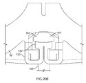
- FIGS. 20A and 20B are details of a frame of a valve prosthesis that includes a receptacle including a cantilever spring, showing a track and locking elements being formed therein.
- FIGS. 20C and 20D are perspective and side details, respectively, of the receptacle of FIGS. 20A and 20B receiving a guide rail therethrough, the locking elements on the cantilever spring causing the cantilever spring to defect outwardly to accommodate locking tabs on the guide rail passing through the receptacle.
- FIG. 20E is a side detail of the frame of FIGS. 20A-20D with the locking tabs of a guide rails engaged with the locking elements of the receptacle and a top portion of the guide rails severed and removed.
- FIGS. 21A-21D are perspective views of a biological annulus with a valve assembly including a gasket member and a valve prosthesis (with leaflets omitted for clarity) implanted therein.
- FIGS. 22A and 22B are side views of another embodiment of a valve holder tool for delivering a valve prosthesis into a biological annulus.
- FIGS. 23A and 23B are details showing a free end of a guide rail being received within an actuator of the valve holder tool of FIGS. 22A and 22B .
- FIGS. 24A and 24B are front and back views, respectively, of a receptacle that may be attached to a valve prosthesis.
- FIGS. 25A and 25B are perspective views of a frame for a valve prosthesis including the receptacle of FIGS. 24A and 24B attached thereto.
- FIG. 26 is a detail showing a guide rail being received within the receptacle of FIGS. 25A and 25B .
- FIGS. 1 and 2 show an exemplary embodiment of a heart valve assembly 10 that generally includes a gasket member 12 and a valve member 14 .
- the gasket member 12 is an annular shaped body generally defining a plane 16 and a central longitudinal axis 17 extending substantially perpendicular to the plane 16 .
- the gasket member 12 includes an annular ring 18 , a sewing cuff 20 , and a plurality of elongate leaders, guide rails, or other elements 50 extending from the sewing cuff 20 or other portion of the gasket member 12 , as described further below.
- the gasket member 12 may also include a flexible skirt and/or baleen elements (not shown), e.g., surrounding the annular ring 18 , a collar, and/or a plurality of guide shields (also not shown), similar to other embodiments described herein.
- a fabric covering 21 may be provided on one or more components of the gasket member 12 , e.g., over the annular ring 18 and over a core of the sewing cuff 20 , as described further below.
- the annular ring 18 may have a generally circular shape.
- the annular ring 18 may have a multi-lobular shape about the circumference, e.g., including three lobes separated by scallops or cusps (not shown) depending upon the anatomy within which the annular ring 18 is to be introduced.
- the annular ring 18 may be formed from an elastic or superelastic material, for example, metal, such as Nitinol, stainless steel, and the like, a polymer, or a composite material. Such material may facilitate compression and/or expansion of the annular ring 18 , as described further below.
- the annular ring 18 may be cut from a flat sheet of base material having a desired thickness for the annular ring 18 , for example, by laser cutting, mechanical cutting, and the like.
- the annular ring 18 may be initially formed as a long band of material, having a width corresponding to the desired width of the annular ring 18 and a length corresponding to the desired circumference of the annular ring 18 .
- the band may be wrapped around a mandrel or otherwise restrained in a generally cylindrical shape with the ends adjacent to one another, and the band may be heat treated or otherwise processed to program the generally cylindrical shape into the material to create the annular ring 18 .
- the generally cylindrical shape may include the ends overlapping one another, spaced apart from one another to provide an open “C” shape, or attached to one another.
- the annular ring 18 may be manufactured from a solid rod of material, e.g. Nitinol, stainless steel, a polymer, or composite material, e.g., by machining, electrical discharge machining (“EDM”), laser cutting, or other processes.
- the annular ring 18 may be heat treated to program a shape memory into the band material, e.g., when the material is in an austentic state.
- the programmed shape may be an enlarged or relaxed condition, e.g., having a substantially circular shape.
- the composition of the material may be such that the annular ring 18 transforms to a substantially martensitic state substantially below body temperature, e.g., at or below ambient temperatures (e.g., 20° C. or less).
- the annular ring 18 may be relatively soft such that the annular ring 18 may be plastically compressed or otherwise deformed, e.g., into a contracted condition to facilitate delivery, as described below.
- a transition temperature of the material may be set such that the annular ring 18 transforms substantially back to an austenitic state close to or at about body temperature (e.g., at 37° C. or more).
- body temperature e.g., at 37° C. or more.
- the material may be programmed to assume an austenitic state at both ambient and body temperatures, but within the elastic or superelastic range of the material.
- the annular ring 18 may be elastically compressed into the contracted condition, but may resiliently expand towards the enlarged condition when released from any constraints maintaining the annular ring 18 in the contracted condition.
- the annular ring 18 may be at least partially covered with fabric, e.g., for tissue ingrowth, by wrapping fabric around the annular ring 18 , while accommodating expansion and contraction of the annular ring 18 .
- fabric e.g., for tissue ingrowth
- the fabric may not be secured to the annular ring 18 , allowing the ends to slide circumferentially relative to the fabric.
- sutures and the like may be used to secure the fabric to the annular ring 18 at locations removed from the ends, e.g., at an intermediate location about the circumference of the annular ring 18 .
- the entire annular ring 18 may be free to slide within the fabric wrapped around the annular ring 18 .
- the sewing cuff 20 may be attached to or otherwise extend around the annular ring 18 .
- the sewing cuff 20 may simply be one or more layers of fabric or other material covering at least a portion of the annular ring 18 .
- a layer of fabric 21 may cover all of the annular ring 18 (other than any connectors and/or bearing surfaces, if any) and/or may include a section of material extending radially outwardly from the annular ring 18 to at least partially define the sewing cuff 20 .
- the sewing cuff 20 may include flexible core material (not shown) that may be attached to or otherwise extend around the annular ring 18 .
- the core may be secured around the annular ring 18 by an interference fit, bonding, fusing a portion of the core to the annular ring 18 , e.g., along an upper edge thereof, and the like.
- the core may be substantially covered with fabric, similar to the annular ring 18 .
- the core may include a lattice (not shown) extending around a circumference of the core, e.g., including at least two spaced apart circumferential elements and a plurality of ribs or transverse elements extending between the circumferential elements, thereby defining openings through the lattice.
- the openings may be completely open, i.e., free from any material.
- the openings may be recesses including a relatively thin wall of core material, i.e., that is substantially thinner than the circumferential elements and/or ribs.
- the core may include a base or web and a plurality of fins or ribs extending from the web to provide a flexible structure, e.g., which may facilitate sealing between the sewing cuff 20 and valve member 14 .
- Exemplary materials for the core include silicone or other elastomeric materials, foam, fabric, felt, polymers, and the like.
- the core may include swellable material, e.g., foam or sponge materials that may expand when exposed to fluid, such as blood.
- the materials may be molded or otherwise formed into the core, e.g., using known molding, extrusion, cutting, or other manufacturing procedures.
- the core may be injection molded or otherwise formed in its annular shape.
- the core may be molded or otherwise formed as a flat sheet, and rolled into the annular shape.
- the ends of the sheet may be attached to one another, e.g., using sutures, adhesives, ultrasonic welding, and the like.
- one or more wedges may be cut out of the band to provide a desired tapered but annular shape.
- portions of the core may be disconnected from other portions, e.g., to prevent puckering. For example, if the core is formed from a rolled sheet (not shown), ends of the sheet (also not shown) may remain loose to allow the ends to move relative to one another.
- the sewing cuff 20 may adopt an undulating annular shape or a generally planar annular shape.
- the sewing cuff 20 may also be tapered, as shown in FIGS. 1 and 2 , e.g., having a larger diameter or circumference about an upper edge than about an edge adjacent the annular ring 18 .
- the tapered shape of the sewing cuff 20 may define an angle relative to the longitudinal axis 17 , e.g., between about twenty and forty five degrees (20-45°).
- the material of the core may be substantially flexible, e.g., manufactured in a desired annular shape, yet easily deformed, e.g., deflected, stretched, and/or compressed.
- the core may be sufficiently flexible to be “floppy,” i.e., such that the core conforms easily to the particular anatomy and/or implantation arrangements encountered during implantation.
- the core when the sewing cuff 20 is placed above or within a biological annulus within a patient's heart, the core may conform to the surrounding anatomy and/or may deform when the valve member 14 is secured to the gasket member 12 , e.g. to enhance sealing between the valve member 14 and the gasket member 12 , as described further below. Additional information on flexible cores or other constructions of the sewing cuff 20 may be found in U.S. Publication No. US 2006/0195184, filed as Ser. No. 11/069,081, the entire disclosure of which is expressly incorporate by reference herein.
- the leaders 50 may include elongate rails, fibers, or filaments including a first or distal end 51 attached or otherwise secured to the gasket member 12 and a second or proximal end 52 .
- the leaders 50 may include one or more markers or other elements (not shown) spaced apart along at least a portion of their lengths, e.g., immediately adjacent the first end 51 .
- the leaders 50 may include one or more unidirectional or bidirectional retention elements 54 , e.g., locking beads, tabs, ratchets, detents, and the like. As explained further elsewhere herein, these leaders may also provide connectors for attaching and/or securing the valve member 14 to or adjacent the gasket member 12 .
- the leaders 50 may be threads, filaments, wires, rails, or other tethers that extend from the gasket member 12 .
- the leaders 50 may be monofilaments or multifilament structures, e.g., braided, spun, or otherwise formed into a unitary member.
- the leaders 50 may be formed from wire or suture materials, e.g., plastic, such as polyethylene, metal, such as stainless steel, cat gut, or composite materials, using known methods.
- the leaders 50 may be stiff or flexible, and/or may be resiliently bendable or plastically pliable.
- the retention elements 54 may be integrally formed on the leaders 50 , e.g., at the time the leaders 50 are formed, or may be separate elements (made from the same or different materials than the leaders 50 ) that are bonded, fused, or otherwise attached to the leaders 50 at predetermined locations.
- the leaders 50 may be flat bands, e.g., formed from plastic or other material, and may have the retention elements 54 formed therein or attached thereto, as described elsewhere herein.
- the retention elements 54 may include tapered proximal edges 54 a and substantially blunt distal edges 54 b .
- the proximal edges 54 a may provide a substantially smooth transition allowing the valve member 14 to be passed distally over the retention elements 54 .
- the distal edges 54 b may provide locks that prevent the valve member 14 from being passed proximally back over the retention elements 54 , similar to a ratchet or detent, as described further below.
- the retention elements on the leaders 50 may include knots (not shown) tied onto the leaders 50 and/or beads (also not shown) formed on the leaders 50 at predetermined locations. Although only one retention element 54 is shown on each leader 50 , optionally, multiple retention elements 54 may be provided spaced apart from one another along each leader 50 .
- Each leader 50 may be attached to, pre-threaded through, or otherwise placed on the gasket member 12 , e.g., at spaced apart intervals from one another.
- leaders 50 may be provided on the gasket member 12 that are aligned with the commissures (not shown) on the valve member 14 and/or a biological annulus into which the gasket member 12 is to be implanted.
- three leaders 50 may be provided, as shown.
- Each leader 50 may be attached to the gasket member 12 by directing the first end 51 through a predetermined location in the gasket member 12 and melting or otherwise expanding the first end 51 (e.g., similar to a rivet or nail head) to prevent subsequent removal.
- the first end 51 may be looped back around the leader 50 and bonded, fused, tied, or otherwise secured to the leader 50 .
- the first end 51 may be pulled and secured or disposed adjacent the second end 52 (not shown), e.g., similar to a double-arm suture.
- the leaders 50 may be attached to the fabric of the sewing cuff 20 immediately adjacent the annular ring 18 , or to other portions of the gasket member 12 , e.g., to the annular ring 18 , the core of the sewing cuff (not shown), or other portions of the fabric covering of gasket member 12 .
- the gasket member 12 may include one or more additional components.
- the gasket member 12 may include a collar or stand-off 58 that extends upwardly from the sewing cuff 20 for receiving the valve member 14 , such as that shown in FIG. 8C .
- a skirt or a plurality of baleen elements may be provided around or adjacent the annular ring 18 , e.g., that may bias a portion of the fabric covering outwardly (also not shown). Additional information on materials, construction, and/or components of the gasket member 112 may be found in U.S. Publication Nos. US 2004/0122516, filed as Ser. No. 10/327,821, US 2005/0165479, filed as Ser. No.
- the gasket member 12 may be expandable and/or compressible such that the cross-section of the gasket member 12 may be adjusted, e.g., to accommodate introduction into a patient's body during a procedure, as described further elsewhere herein.
- the annular ring 18 may be biased to a relaxed or expanded condition, e.g., defining a predetermined diameter “D 1 ” (as shown in FIG. 3A ). At least a portion of the annular ring 18 may be contracted radially inwardly to define a smaller diameter or cross-section “D 2 ” (as shown in FIG. 3B ), e.g., to facilitate delivery into a biological annulus.
- the sewing cuff 20 may be substantially flexible such that the sewing cuff 20 is also compressed radially inwardly as the annular ring 18 is compressed.
- the gasket member may be compressible, yet may be resiliently expandable to dilate tissue surrounding the annulus and/or to facilitate securing the gasket member 12 within a biological annulus.
- tension may be applied to the leaders 50 (e.g., using delivery tool 60 , described further below), e.g., to draw one or more portions of the gasket member 12 inwardly towards the central axis 17 .
- inward and/or proximal tension may be applied to the leaders 50 , e.g., by pulling the leaders 50 at least partially into the delivery tool 60 , as described further below, which may pull the ends of the leaders 50 inwardly towards the central axis 17 .
- the annular ring 18 may contract inwardly to assume a multiple lobular shape, e.g., as shown in FIG. 3B , such that the gasket member 12 assumes the contracted condition.
- the annular ring 18 may deform elastically towards the contracted condition.
- the annular ring 18 may be cooled to a martensitic state, e.g., by immersing the gasket member 12 in ice, ice water, or other fluid maintained at a temperature below the final martensitic temperature of the annular ring 18 .
- the annular ring 18 may be plastically deformed while the annular ring 18 is in the relatively soft, martensitic state.
- the annular ring 18 may resiliently expand outwardly, e.g., to a shape having a generally circular cross-section, thereby returning the gasket member 12 towards the expanded condition, e.g., as shown in FIG. 3A .
- the annular ring 18 may simply expand resiliently towards the expanded condition.
- the gasket member 12 may be heated such that the annular ring 18 resumes an austenitic state, e.g., when the annular ring 18 is exposed to ambient temperatures or body temperature.
- the annular ring 18 may “remember” the expanded condition and become biased to expand upon being released.
- FIG. 2 an exemplary embodiment of an apparatus or system 30 is shown for delivering a prosthesis into a biological annulus that includes a gasket member 12 and a delivery tool 60 .
- the gasket member 12 may be any of the embodiments described herein, e.g., including an annular ring 18 , a sewing cuff 20 , and a plurality of elongate leaders 50 .
- the delivery tool 60 generally includes a shaft 62 having a proximal end 61 , a distal end 63 sized and/or shaped for introduction into an opening in a patient's body, and a handle 65 on the proximal end 61 .
- the delivery tool 60 may also include one or more lumens 67 (one shown in phantom) extending between the proximal and distal ends 61 , 63 , e.g., for receiving portions of the leaders 50 therein.
- the shaft 62 may include other configurations, e.g., a “U” shaped cross-section defining a channel for receiving the leaders 50 therein. Such a cross-section may facilitate loading the leaders onto the delivery tool 60 .
- the handle 65 may also include one or more actuators 66 , 68 , e.g., one or more locking, tightening, and/or loosing mechanisms for manipulating the leaders 50 .
- the delivery tool 60 may include a locking mechanism 64 for releasably securing the second ends of the leaders 50 , e.g., one or more clamping structures, detents, and the like.
- the actuators 66 , 68 may allow the second ends of the leaders 50 to be directed proximally or distally, e.g., to apply or release tension, as described further below.
- the locking mechanism 64 includes a lever 66 that may be actuated to release the second ends of the leaders 50 , and a latch 68 that may be actuated to increase and/or decrease tension applied to the leaders 50 .
- the leaders 50 may be loaded into the distal end 63 of the delivery tool 60 and through the lumen 67 until the second ends are engaged or otherwise received by the locking mechanism 64 .
- the leaders 50 may be loaded by a user shortly before a procedure, e.g., allowing a gasket member 12 of a desired size “D 1 ” to be selected and loaded onto the delivery tool 60 .
- the leaders 50 may be preloaded into a delivery tool 60 during manufacturing, although this may require providing multiple delivery tools 60 before a procedure, each carrying a different size gasket member 12 .
- the latch 68 may be actuated to pull the leaders 50 proximally a predetermined distance within the delivery tool 60 . This action may pull the gasket member 12 proximally against the distal end 63 of the delivery tool 60 and/or radially inwardly, as shown in FIG. 3B .
- the tension may be selected to compress the gasket member 12 to a predetermined size and/or shape. As shown in FIG. 3B , the gasket member 12 has been compressed into a three lobe clover-like shape having a cross-section “D 2 .”
- the tension may be applied by a user shortly before introducing the gasket member 12 into a patient or the tension may be preloaded, e.g., during manufacturing.
- the lever 66 When it is desired to deploy the gasket member 12 , the lever 66 may be actuated, thereby releasing the leaders 50 from the delivery tool 60 .
- the tension on the leaders 50 may be released by actuating the latch 68 , e.g., in the opposite direction, from that used to apply the tension, without releasing the leaders 50 entirely from the delivery tool 60 .
- the lever 66 and latch 68 may be combined into a single actuator having multiple settings or positions, depending upon the action desired (e.g., tension, tension release, fully release).
- a delivery tool may be provided that includes a tubular body or other structure into which the entire gasket member 12 may be loaded, e.g., after compressing the gasket member 12 to the contracted condition.
- the delivery tool may include a plunger or other device (not shown) within the tubular body that may be used to deploy the gasket member 12 from the tubular body.
- the gasket member 12 may be compressed by flattening the annular ring 18 along the plane 16 and then folding or rolling the resulting flattened annular ring 18 .
- the annular ring 18 may be rolled into a spiral, folded in half, e.g., into a “C” shape, such as that shown in FIG. 12 , or otherwise compressed.
- the annular ring 18 may resiliently return to its expanded condition, similar to the other embodiments described elsewhere herein. Additional information regarding apparatus and methods for using such as gasket member and/or heart valve assembly may be found in U.S. Publication No. 2007/0016288, filed as Ser. No. 11/457,437, the entire disclosure of which is expressly incorporated by reference herein.
- the valve member 14 generally includes an annular shaped body or frame 32 and one or more valve elements 33 .
- the valve member 14 may include a fabric covering 35 , similar to the gasket member 12 , e.g., covering the frame 32 and/or other components of the valve member 14 .
- the frame 32 may have a noncircular, e.g., multiple lobular shape corresponding to a shape of the biological annulus within which the valve member 14 is to be implanted.
- the valve member 14 may have a tri-lobular shape, including three lobes separated by cusps or scallops, e.g., corresponding to a sinus of Valsalva above an aortic valve site.
- the valve member 14 may be a bioprosthetic valve member, e.g., an annular frame 32 carrying a plurality of tissue leaflets 33 .
- the frame 32 may include a plurality of struts (also not shown for clarity) that may be attached to and/or otherwise carry the leaflets 33 .
- the struts may include a laminate structure, including two or more sheets of flexible material, similar to the valves disclosed in U.S. Pat. No. 6,371,983, and U.S. Publication No. US 2006/0276888, filed as Ser. No. 11/144,254, the entire disclosures of which are expressly incorporated by reference herein.
- valve member 14 may be a connecting device to which a valve (not shown) may be connected or that may otherwise receive a valve component, such as the connection adapter elements shown in U.S. Publication No. US as 2005/0043760, filed as Ser. No. 10/646,639, the entire disclosure of which is expressly incorporated by reference herein.
- valve 14 may include a mechanical valve or other valve (not shown), such as those disclosed in US 2005/0165479 and US 2007/0016285725, incorporated by reference above.
- the valve member 14 may include one or more introducers or receivers 76 through which leaders 50 may be received.
- a first embodiment of an introducer 76 is shown that includes a tubular member 76 received through a portion of the valve member 14 .
- the tubular members 76 may simply be removably inserted through predetermined regions of a fabric covering on the frame 32 , e.g., such that the tubular members 76 extend substantially parallel to the longitudinal axis 17 .
- tubular members 76 are located at commissures 34 of the frame 32 , although alternatively, the tubular members 76 may be located at other desired angular locations around the frame 32 corresponding to the locations of the leaders 50 on the gasket member 12 (not shown in FIG. 6 ; see, e.g., FIG. 1 ).
- the tubular members 76 may be formed from a variety of materials, e.g., a section of hypotube, made from metal, such as stainless steel, plastic, or composite materials.
- the tubular members 76 may be preloaded onto the frame 32 , e.g., during manufacturing, or loaded onto the frame 32 shortly before a procedure. As described further below, the tubular members 76 may be removed from the frame 32 at any time, e.g., immediately before or after securing the valve member 14 to the gasket member 12 .
- FIG. 7 shows another embodiment of introducers 76 ′ that may be provided directly on the valve member 14 .
- the introducers 76 ′ are formed from a piece of fabric or other material 78 ′ attached to the fabric covering the valve member 14 , thereby defining a pocket or passage 79 ′ therethrough.
- the introducers 76 ′ may be a rectangular section of material whose side edges are stitched, bonded, or otherwise attached to the fabric covering or other portion of the valve member 14 , or a separate tubular structure.
- the leaders 50 may be introduced through the fabric itself of valve member 14 , e.g., using a needle or other tool (not shown) on the second ends of the leaders 50 to “pick up” one or more threads of the fabric. Additional information on introducers or receivers may be found in US 2005/0165479, incorporated by reference herein.
- the heart valve assembly 10 may be implanted within a patient's body, e.g., within or adjacent to a biological annulus 90 .
- the biological annulus 90 may be the site for replacing an existing natural or previously implanted heart valve, such as a tricuspid, mitral, aortic, or pulmonary valve within a patient's heart (not shown).
- the patient Before implanting the heart valve assembly 10 , the patient may be prepared for the procedure using known methods. For example, the patient may be placed on cardiopulmonary bypass (CPB), and the patient's heart may be exposed, e.g., by sternotomy, thoracotomy, or other open or minimally invasive procedure. An incision may be created in the blood vessel above the valve being replaced (not shown), e.g., the aorta for an aortic valve replacement, in order to access the annulus 90 . The existing natural or prosthetic heart valve and/or leaflets (also not shown) may be removed from the annulus 90 using known methods.
- CPB cardiopulmonary bypass
- a heart valve assembly 10 may be selected based upon the anatomy encountered, e.g., having a plurality of lobes, matching the lobes of the biological annulus 90 and/or having a cross-sectional dimension corresponding to the interior cross-section of the biological annulus 90 .
- a gasket member 12 and/or valve member 14 may be selected having a size that is larger than the biological annulus 90 .
- the gasket member 12 may have a diameter in its relaxed condition that is slightly larger than the biological annulus 90 , e.g., such that the gasket member 12 may at least partially dilate the biological annulus 90 upon implantation.
- the valve member 14 may have a diameter or other cross-section that is substantially larger than the biological annulus 90 , e.g., for supra-annular or intra-sinus implantation, which may accommodate the larger size.
- the gasket member 12 may be restrained in the contracted condition, e.g., by the delivery tool 60 .
- the gasket member 12 may include leaders 50 and the delivery tool 60 may be provided with the leaders 50 preloaded into the delivery tool 60 .
- the leaders 50 may be provided initially in a relaxed state, i.e., without subjecting the gasket member 12 to any tension or other stress, e.g., to prevent fatigue of components and/or materials of the gasket member 12 .
- the user may actuate the latch 68 to apply tension to the leaders 50 , e.g., to compress the gasket member 12 inwardly to the contracted condition shown in FIG. 5A .
- the gasket member 12 may be placed in ice water or otherwise chilled, e.g., to “soften” or place the annular ring 18 in a martensitic state, as described elsewhere herein.
- the predetermined tension may pull the gasket member 12 onto or around the distal end 63 of the delivery tool 60 , thereby stabilizing and/or securing the gasket member 12 relative to the distal end 63 , e.g., to facilitate introduction into the patient's body.
- the leaders 50 may be pre-tensioned by the delivery tool 60 before use, e.g., during manufacturing, as described above.
- the user may load the leaders 50 into the deliver tool 60 immediately before the procedure, and then apply the desired tension to compress and/or stabilize the gasket member 14 .
- This alternative may be particularly desirable when a single delivery tool 60 is used to deliver one of various sized gasket members available to the user.
- the physician may measure the size of the biological annulus 90 and select an appropriate gasket member 12 (and/or valve member 14 ) based upon the specific anatomy encountered.
- the gasket member 12 may be introduced into the patient's body and advanced into the biological annulus 90 , e.g., by directing the distal end 63 of the delivery tool 60 into the patient's body.
- the gasket member 12 may be advanced until the annular ring 18 extends at least partially into the biological annulus 90 .
- the annular ring 18 may extend through the biological annulus 90 , i.e., with a lower edge of the annular ring 18 disposed within the sub-annular space below the biological annulus 90 .
- the gasket member 12 may include a flexible skirt (not shown) that may surround and/or extend from the annular ring 18 through the biological annulus 90 . The skirt may be biased to extend outwardly to provide a smooth transition and/or enhance a seal between the gasket member 12 and the biological annulus 90 .
- the gasket member 12 may then be expanded or at least partially released within the biological annulus 90 , e.g., to dilate the biological annulus 90 or otherwise direct the surrounding tissue 98 outwardly.
- the latch 68 on the delivery tool 60 (not shown, see FIG. 2 ) may be actuated to remove the tension on the leaders 50 , whereupon the annular ring 18 may resiliently expand against the tissue surrounding the biological annulus 90 . This may substantially stabilize or secure the gasket member 12 relative to the biological annulus 90 .
- the leaders 50 may be released entirely from the delivery tool 60 , e.g., by actuating lever 66 (not shown, see FIG. 2 ).
- a dilation tool (not shown) may be advanced into the gasket member 12 and expanded to forcibly (e.g., plastically) expand the annular ring 18 within the biological annulus 90 .
- the sewing cuff 20 may contact the tissue surrounding the supra-annular space above the biological annulus 90 , as shown in FIG. 5B .
- One or more fasteners 96 e.g., clips, staples, sutures, and the like, may be directed through the gasket member 12 into the tissue 98 above and/or surrounding the biological annulus 90 .
- a plurality of clips 96 may be driven through the sewing cuff 20 into the surrounding tissue 98 , similar to the method shown in FIGS. 14A-14C and described elsewhere herein.
- Exemplary fasteners and methods for using them to secure the gasket member 112 may be found in U.S. Publication Nos.
- the valve member 14 may then be advanced into the patient's body towards the biological annulus 90 .
- the valve member 14 may be advanced along the leaders 50 toward the gasket member 12 .
- the second or free ends 52 of the leaders 50 may be directed through respective portions of the valve member 14 .
- the leaders 50 need to be released and/or removed completely from the delivery tool 60 , as described above.
- the leaders 50 may be directed through respective portions of the fabric covering 35 , e.g., adjacent the commissures 34 .
- the second ends 52 of the leaders 50 may include needles (not shown) that may be directed through desired portions of the fabric covering 35 to pick up one or more threads.
- the valve member 14 may include receptacles (not shown) attached to the frame 32 and/or fabric covering 35 , and the fabric covering 35 may include slits or other openings through which the leaders 50 may be introduced to pass the leaders 50 through the receptacles, e.g., similar to the embodiments shown in FIGS. 20A-20E and FIGS. 24A-26 and described elsewhere herein.
- valve member 14 includes introducers 76
- the second ends 52 of the leaders 50 may be backloaded through respective introducers 76 .
- the valve may include receivers 76 ′ through which the leaders 50 may be directed.
- the valve member 14 may be advanced distally over the leaders 50 towards the gasket member 12 , i.e., in the direction of arrow 94 , until the valve member 14 engages or otherwise contacts the gasket member 12 .
- the leaders 50 may include ratcheting or other retention elements 54 over which the valve member 14 may pass.
- the retention elements 54 may include tapered proximal edges 54 a , which may provide a smooth transition that allows the retention elements 54 to pass freely through the fabric covering 35 , receptacles (not shown), or introducers 76 , 76 .′ Because of the blunt distal edges 54 b , however, the valve member 14 may not be withdrawn back over the retention elements 54 . Thus, the retention elements 54 may allow unidirectional advancement of the valve member 14 , i.e., towards the gasket member 12 .
- the retention elements 54 may be disposed a predetermined distance from the first ends 51 of the leaders 50 , thereby securing the valve member 14 against or immediately adjacent the gasket member 12 .
- the predetermined distance may be set such that the frame 32 of the valve member 14 substantially contacts the sewing cuff 20 , e.g., to at least partially compress the core, which may enhance sealing between the valve member 14 and the gasket member 14 .
- one or more knots may be directed down the leaders 50 after the valve member 14 engages or contacts the gasket member 12 .
- the gasket member 12 includes a collar (not shown, see, e.g., FIG. 8C ) extending above the sewing cuff 20
- the collar may include a drawstring or other connector(s) (also not shown) that may be tightened around the frame 32 of the valve member 14 to secure the valve member 14 relative to the gasket member 12 .
- valve member 14 and/or gasket member 12 may include one or more cooperating connectors, e.g., clips, detents, and the like, that may self-engage when the valve member 14 is docked to the gasket member 12 , similar to the embodiments described in the references incorporated by reference above.
- cooperating connectors e.g., clips, detents, and the like
- the leaders 50 may be cut or otherwise severed, thereby providing a heart valve assembly 10 implanted within the biological annulus 90 . As shown, the leaders 50 are severed above the retention elements 54 used to secure the valve member 14 to the gasket member 12 . If the leaders 50 are knotted to secure the valve member 14 to the gasket member 12 , the leaders 50 may be severed above the knots. Optionally, the leaders 50 may include weakened regions (not shown) above the retention elements 54 or otherwise disposed a predetermined distance from the first ends 51 .
- the weakened regions may automatically fail, thereby separating the first ends 51 from the remainder of the leaders 50 , which may then be removed from the patient's body.
- This alternative may eliminate the need to introduce scissors or other cutting tools into the patient to cut the leaders 50 .
- the remaining leaders may be cut below the retention elements 54 to release the valve member 14 , allowing the valve member 14 to be removed from the gasket member 12 and/or patient's body.
- the introducers 76 may be removed from the valve member 14 immediately before, while, or immediately after the valve member 14 is secured to the gasket member 12 .
- the introducers 76 may be removed simply by directing the introducers 76 proximally over the leaders 50 , i.e., out of the fabric or frame of the valve member 14 and over the second ends 52 of the leaders 50 .
- the introducers 76 ′ may be pockets formed from fabric, metal, or polymeric material, separately attached or integrated with the frame 32 and/or fabric covering 35 of the valve member 14 .
- the introducers 76 ′ may interact with the retention elements 54 on the leaders 50 to prevent removal of the valve member 14 away from the gasket member 12 .
- FIGS. 8A and 8B another embodiment of a gasket member 112 is shown that includes an annular ring 118 , a sewing cuff 120 , and a plurality of elongate guide rails or other leaders 150 extending from the sewing cuff 120 or other portion of the gasket member 12 , e.g., similar to other embodiments herein.
- the gasket member 112 may also include a flexible skirt and/or baleen elements (not shown), e.g., surrounding the annular ring 118 .
- a fabric covering may be provided on one or more components of the gasket member 112 , e.g., over the annular ring 118 and over a core of the sewing cuff 120 , also as described elsewhere herein.
- the gasket member 112 includes a plurality of guide shields 156 removably attached to the gasket member 112 , e.g., by one or more sutures to the sewing cuff 120 .
- the guide shields 156 may extend upwardly and/or outwardly from the sewing cuff 120 , e.g., to at least partially define a passage 124 for guiding a valve prosthesis (not shown) downwardly towards the gasket member 112 , as described further below.
- the guide shields 156 may extend diagonally outwardly from the gasket member 112 , but may be deflectable radially inwardly towards a central axis 117 of the gasket member 112 , e.g., during delivery.
- the guide shields 156 may be formed from a relatively thin and/or transparent sheet, e.g., a plastic such as polyester or Mylar or any other polymeric film or material, such as high-density or low-density polyethylene, polystyrene, and the like.
- the sheet may be cut or otherwise formed to include one or more bands, e.g., defining a relatively wide base that may be attached to the gasket member 112 and a relatively narrow loose upper end.
- the guide shields 156 may have a generally triangular shape, e.g., with a wider base 156 a and a narrower upper end 156 b .
- a center of the guide shields may be removed to provide diagonal or inverted “V” bands extending from the upper end 156 b down to the base 156 a .
- the guide shields 156 may have a substantially continuous “mandolin” or inverted “Y” shape, as shown in FIG. 8B , and described further in co-pending application Ser. No. 60/914,742, incorporated by reference herein.
- the upper ends 156 b may include one or more features that partially restrain the guide rails 150 away from the passage 124 or otherwise out of the operator's field of view during a procedure.
- the upper ends 156 b may include one or more bands 159 that may be wrapped around the guide rails 150 to releasably constrain the guide rails 150 to the guide shields 156 .
- the upper ends 156 b may include openings 158 that may receive the guide rails 150 .
- the upper ends 156 b of the guide shields 156 may be split, e.g., at 158 a down to the openings 158 or diagonally from the openings 158 (not shown), to facilitate inserting and/or removing the guide rails into/from the openings 158 , as shown in FIG. 8B .
- the guide shields 156 may be attached to the sewing cuff 120 , e.g., by one or more sutures (not shown) sewn through fabric of the sewing cuff 120 (and/or other portion of the gasket member 12 ) and holes (also not shown) in the base 156 a .
- a chain stitch or other stitch may be used, e.g., that may unravel upon being cut at a single location, which may facilitate removing the sutures and, consequently, the guide shields 156 after implantation. Additional information on methods for removably attaching the guide shields 156 to the gasket member and/or methods for using the guide shields 156 may be found in co-pending application Ser. No. 60/914,742, incorporated by reference herein.
- FIGS. 9A-9C an exemplary embodiment of a gasket delivery tool 160 is shown that generally includes an elongate shaft 162 including a proximal end 161 , a distal end 163 , and an actuator 165 on the proximal end 161 .
- the delivery tool 160 includes a plurality of supports 166 on the distal end, e.g., spaced apart around a longitudinal axis 167 of the tool 160 .
- the supports 166 may be substantially rigid cylindrical hubs for receiving a gasket member 112 (such as any of those described herein) around the supports 166 .
- the supports 166 may generally define a diameter that is smaller than the gasket member 112 , e.g., smaller than the radius of the annular ring 118 .
- the supports 166 may be formed as a single piece, e.g., integrally molded, machined, and the like, or may be separate shafts and/or other components attached to one another and/or the distal end 163 of the gasket delivery tool 160 .
- a hub or base having a circular or other multiple lobed shape may be provided instead of the supports 166 , if desired.
- the tool 160 includes a plurality of arms 168 movably mounted to the distal end 163 .
- one end 168 a of the arms 168 may be attached to the distal end 163 of the tool 160 , e.g., proximal to the supports 166 , and the other free end may include tips 168 b disposed adjacent the supports 166 .
- the arms 168 may be offset radially relative to the supports 166 such that each arm 168 is disposed between adjacent supports 166 .
- the arms 168 may be movable from an outer position, e.g., as shown in FIGS.
- the actuator 165 may include a lever or other mechanism that may selectively move the tips 168 b of the arms 168 between the outer and inner positions.
- the actuator 165 may include a handle 165 a coupled to a sleeve 165 b via a linkage 165 c .
- the handle 165 a may be biased outwardly, e.g., by a spring 165 d or other biasing mechanism, thereby maintaining the arms 168 in the outer position.
- the handle 165 a may be directed towards the shaft 162 , e.g., about pivot point 165 e , thereby directing linkage 165 c and sleeve 165 b distally, i.e., towards the distal end 163 . This action causes the tips 168 b of the arms 168 to move inwardly towards the inner position.
- the arms 168 may be deflectable radially inwardly by an inward force applied to the arms 168 as the sleeve 165 b passes over the first ends 168 a .
- the arms 168 may be sufficiently resilient to return outwardly when the sleeve 165 b is retracted from over the first ends 168 a .
- the arms 168 may include hinges or other components coupled to the sleeve 165 b and/or linkage 165 c such that the arms 168 are movable inwardly and outwardly.
- the handle 165 a may be temporarily locked against the shaft 162 with the arms 168 in the inner position, e.g., by a lock or other interlocking features (not shown) on the handle 165 a , linkage 165 c , and/or shaft 162 .
- the linkage 165 c may include a slot 165 f and the handle 165 a may include a sliding button, switch or other control 165 g that includes a cross pin 165 h that may be received in the slot 165 f when the handle 165 a is directed against the shaft 162 .
- the control 165 g may be manually moved to engage and/or disengage the cross pin 165 h and the slot 165 f
- the control 165 g may be biased, e.g., towards or away from the end of the handle 165 a , for example by a spring (not shown), such that when the handle 165 a is directed against the shaft 162 , the cross pin 165 h slides into the slot 165 f , preventing subsequent movement of the handle 165 a .
- the control 165 g may be directed against the bias of the spring, e.g., distally or proximally, to release the cross pin 165 h from the slot 165 f , whereupon the spring 165 d may then bias the handle 165 a outwardly.
- the slot 165 f may be oriented to engage with the cross pin 165 h as the control 165 g is translated along the handle 165 a in a distal or proximal direction, and to release the cross pin 165 h as the control 165 g is translated in an opposite proximal or distal direction.
- the control 165 g may be released, whereupon the spring 165 d may then bias the handle 165 a outwardly, thereby automatically opening the arms 168 towards the outer position.
- the levers involved may be designed such that the bias of the spring 165 d is removed when the handle 165 a is directed against the shaft 162 , thereby maintaining the arms 168 in the inner position.
- the handle 165 a may simply be pulled away from the shaft 162 such that the spring 165 d again biases the handle 165 a to move outwardly, directing the arms 168 to the outer position.
- a gasket member 112 may be placed between the supports 166 and the arms 168 , e.g., with the nadir regions of the sewing cuff 120 aligned radially with the arms 168 and the commissure regions of the sewing cuff 120 aligned radially with the supports 166 .
- the arms 168 may then be directed to the inner position, thereby securing the gasket member 112 between the supports 166 and the arms 168 . As shown in FIGS.
- the gasket member 112 may be deformed from a generally circular expanded condition to a multiple lobed, e.g., “shamrock” shaped contracted condition defining lobes, similar to the other embodiments and tools described above.
- the gasket member 112 may be elastically deformed into the contracted condition or plastically deformed, e.g., in a martensitic state, similar to the previous embodiments.
- the tool 160 may be loaded with the gasket member 112 , as shown in FIG. 11A , and then directed into a biological annulus 90 , e.g., as best seen in FIG. 11B .
- the tool 160 may be rotated about its longitudinal axis 167 to align the lobes or “ears” of the gasket member 112 with the commissures 91 of the biological annulus 90 .
- the arms 168 may then be directed to the outer position, thereby releasing the gasket member 112 .
- the gasket member 112 may resiliently expand towards its original expanded condition when released, thereby contacting tissue surrounding the biological annulus 90 .
- the tool 160 may be removed, leaving the gasket member 112 in place within the biological annulus 90 .
- the annular ring of the gasket member 112 may be located within a native valve annulus, while the sewing cuff 120 may be located in a supra-annular position relative to the native valve annulus.
- the guide rails 150 and/or guide shields 156 may extend upwardly from the biological annulus 90 , e.g., to a location above the biological annulus and/or outside the patient's body, as described elsewhere herein.
- FIG. 12 shows an alternate contracted configuration for the gasket member 112 , which may be used instead of the multiple lobed or “shamrock” contracted condition shown in FIG. 10A .
- the gasket member 112 may be folded into a generally “C” shaped or rolled shape in the contracted condition, rather than the multiple lobed condition.
- Such a folded condition may be maintained by a tool (not shown), e.g., including one or more arms or other actuatable members (also not shown), similar to the arms 168 of the tool 160 .
- the gasket member 112 may simply held by a needle driver, clamp, or other surgical instrument.
- the folded ends of the gasket member 112 may be temporarily secured to one another, e.g., using one or more sutures, a band, and the like (not shown), which may be removed once the gasket member 112 is introduced into the biological annulus 90 .
- the gasket member 112 of FIG. 12 may resiliently unfold or otherwise return back to its original annular shape, similar to when the gasket member 112 is released from the multiple lobed condition.
- the folded condition may allow the gasket member 112 to achieve a smaller cross-section than the multiple lobed condition, which may be useful when access is limited into the biological annulus.
- the gasket member 112 is shown delivered into the biological annulus 90 , e.g., using any of the tools and/or methods described elsewhere herein.
- the guide shields 156 extend upwardly and/or outwardly from the gasket member 112 , thereby contacting surrounding tissue.
- the guide shields 156 may be sufficiently long such that upper ends of the guide shields 156 are disposed outside the patient's body and/or outside the biological annulus 90 .
- the upper ends 156 b of the guide shields 156 may be folded outwardly, e.g., against the patient's chest or other anatomy, to maintain a passage through the guide shields 156 open and/or move the uppers ends 156 b out of the field of view.
- the upper ends 156 b may also be held by sutures, clips, clamps, and the like (not shown), e.g., to help tension or retract the guide shields 156 in order to maintain the field of view open.
- the guide shields 156 may at least partially define a passage communicating with the biological annulus 90 , the inner surfaces of the guide shields 156 providing a smooth and/or lubricious surface to facilitate advancing a valve prosthesis (not shown) into the biological annulus 90 towards the gasket member 112 , as described further elsewhere herein.
- the gasket member 112 may be secured to the surrounding tissue.
- a tool 170 may be used to deliver a plurality of fasteners 96 (not shown) through the sewing cuff 120 and into the surrounding tissue, as described elsewhere herein.
- Forceps, tweezers, or other tool 172 may be used, if desired, to manipulate components of the gasket member 112 during delivery of the fasteners 96 .
- the tool 172 may be used to hold the sewing cuff 120 and/or to move the guide rails 150 and/or guide shields 156 out of the way.
- FIGS. 14A-14C show additional details of securing the gasket member 112 to the surrounding tissue using fasteners 96 .
- valve holder tool 210 may be used to deliver a valve member 14 , which may be any valve prosthesis described elsewhere herein or in the references incorporated by reference.
- a valve member 14 which may be any valve prosthesis described elsewhere herein or in the references incorporated by reference.
- the valve holder 210 includes an elongate shaft 212 including a proximal end 214 and a distal end 216 defining a longitudinal axis 218 therebetween.
- the valve holder 210 may include an enlarged head or support 220 on the distal end 216 , which may have a size and/or shape similar to the valve member 14 carried on the distal end 216 .
- the head 220 may have a partial dome shape, e.g., defining a cavity (not shown) under the head 220 , which may protect or otherwise cover leaflets (not shown) of the valve member 14 .
- the head 220 may include one or more openings 221 therethrough, e.g., for receiving one or more sutures 13 , e.g., as shown in FIG. 17B .
- a suture 13 may be directed through a respective opening 221 and through fabric of the valve member 14 , and then tied off and cut, thereby securing the valve member 14 to the head 220 . Thereafter, during use, e.g., after implantation, the suture(s) 13 may be cut, thereby releasing the valve member 14 from the head 220 , as described further below.
- the valve holder 210 also includes a plurality of tubular members 230 including open upper and lower ends 232 , 233 .
- the tubular members 230 may provide guide passages 230 a for receiving guide rails 150 (not shown) of a gasket member 112 (also not shown), as described further below.
- the tubular members 230 may be attached to the shaft 212 of the valve holder 210 , e.g., by hubs 234 , 236 , such that the tubular members 230 extend generally parallel to the longitudinal axis 218 .
- the tubular members 230 include upper ends 232 that are disposed closer to the longitudinal axis 218 than lower ends 233 , which may facilitate visually monitoring beyond the tubular members 230 .
- the tubular members 230 may extend parallel to the longitudinal axis 218 .
- the tubular members 230 may be disposed against or otherwise closer to the shaft 212 , although the distal ends 233 may then curve outwardly, e.g., in an “S” shape to dispose the distal ends 233 outside the head 220 , e.g., as shown in FIG. 15B .
- valve holder 210 may include one or more actuators for causing separation of at least a portion of the guide rails 150 from the gasket member 112 , as described further below.
- each of the tubular members 230 may be rotatable about an individual central axis 231 , as shown in FIG. 15D .
- the passages 230 a through the tubular members 230 may have a cross-section similar to the guide rails 150 , e.g., having an oblong or rectangular cross-section, which may receive the guide rails 150 in a fixed angular orientation, while accommodating relative axial movement.
- the portion of the guide rails 150 in the passages may also rotate, thereby causing the guide rails 150 to plastically deform and break, e.g., adjacent the distal end 233 of the tubular members 230 .
- the guide rails 150 may include weakened regions that may preferentially break upon rotation of the tubular members 230 .
- the weakened regions may include a notch, slit, groove, cut, necking, thinning, score mark, and/or narrowing on either or both edges of the guide rails 150 , across the entire width of the guide rails 150 , and/or axially or diagonally along the length of the guide rails 150 .
- a preload force or stress may be applied on the guide rails 150 when received within the tubular members 230 that is less than the tensile breaking strength of the guide rails 150 , or, more specifically, less than the tensile breaking strength at the weakened region(s) of the guide rails 150 .
- Such a preload may reduce the number of turns of the tubular members 230 necessary to break or separate the guide rails 150 , e.g., by preventing the guide rails 150 from twisting, binding, and/or bunching excessively during rotation of the tubular members 230 .
- each guide rail 150 may be separated by rotating the respective tubular member 230 .
- the entire hub 234 may be rotatable around the shaft 210 , which may cause all of the guide rails 150 to separate substantially simultaneously at the weakened regions or other locations adjacent the distal ends 263 .
- the valve holder 210 may include an actuator 250 that is movable axially relative to the shaft 212 , e.g., from a distal position (shown in FIG. 16A ) to a proximal position (shown in FIG. 16B ) for breaking the guide rails.
- the actuator 250 may include an outer housing 252 and an inner member 256 disposed adjacent the hub 234 in the distal position.
- the inner member 256 may be coupled to a handle 254 , e.g., such that axial movement of the handle causes the inner member to move axially.
- the outer housing 252 may be rotatable relative to the inner member 256 , e.g., for capturing ends of the guide rails 150 .
- the proximal ends 232 of the tubular members 230 may extend into the hub 234 and communicate with one or more recesses or other features, e.g., recess 253 a between the outer housing 252 and the inner member 256 .
- the outer housing 252 and/or inner member 256 may include one or more locking features, e.g., hooks, catches, ratchets, and the like, such as catch 253 b within the recess 253 a that may receive and/or engage the ends of the guide rails 150 .
- locking features e.g., hooks, catches, ratchets, and the like, such as catch 253 b within the recess 253 a that may receive and/or engage the ends of the guide rails 150 .
- ends of the guide rails 150 may be received within the recess 253 a , e.g., when the guide rails 150 are loaded through the tubular members 230 .
- the outer housing 252 may then be rotated to engage the ends of the guide rails 150 , e.g., with the catch(es) 253 b and/or by at least partially closing the recess 253 a to clamp the ends of the guide rails 150 , thereby preventing the guide rails 150 from being separated from the actuator 250 .
- the catch(es) 253 b may be rotated to engage the ends of the guide rails 150 , e.g., with the catch(es) 253 b and/or by at least partially closing the recess 253 a to clamp the ends of the guide rails 150 , thereby preventing the guide rails 150 from being separated from the actuator 250 .
- the ends of the guide rails 150 may include a slot 153 that may receive or otherwise engage corresponding hooks, catches, ratchets and the like (not shown) within the recess 253 a or otherwise provided on the outer housing 252 and/or inner member 256 .
- a portion of the guide rails 150 may be received in or otherwise engaged with the actuator 250 , e.g., when the guide rails 150 are loaded through the tubular members 230 .
- the actuator 250 When the actuator 250 is moved from the distal position, shown in FIG. 16A , towards the proximal position, shown in FIG. 16B , e.g., by pulling the handle 254 , the guide rails 150 may be pulled by the housing 252 , thereby causing the guide rails 150 to separate at weakened regions or otherwise break, e.g. adjacent the distal ends 263 of the tubular members 230 .
- the actuator 250 may include a lock (not shown) to prevent proximal movement of the actuator 250 until the lock is released.
- the actuator 250 may be rotated about the shaft 212 to engage or disengage a lock between the actuator 250 and the shaft 212 .
- This configuration of the valve holder tool 210 may allow the actuator 250 to be located at a distance proximally from the head 220 . For example, this may facilitate actuation, allowing the user to actuate the valve holder 210 without having to reach into the biological annulus. In addition, this configuration of the valve holder tool 210 may also allow the actuator 250 to be moved a substantial distance away from the head 220 and the implantation site.
- valve holder 210 may be used in a percutaneous implantation or other procedure wherein the actuator is located outside the patient's body, while the head 220 (and valve 14 thereon) are located within the body at the implantation site, e.g., as disclosed in US 2007/0016288, incorporated by reference herein.
- a valve holder tool 210 ′ may include a set of cam-lock features 258 for securing ends of guide rails 150 (not shown, see FIGS. 23A and 23B ) to an actuator 250 .
- the valve holder tool 210 ′ includes an elongate shaft 212 ′ including proximal and distal ends 214 ,′ 216 ,′ a support or head 220 ′ on the distal end 216 ,′ and a plurality of tubular members 230 ,′ similar to the previous embodiments.
- An actuator 250 ′ is slidable on the shaft 212 ,′ e.g., for severing ends of guide rails 150 , similar to the previous embodiment.
- the actuator 250 includes an inner member 256 ′ including guide channels 257 a ′ that communicate with tracks 257 b .′ Openings 257 c ′ above respective tracks 257 b ′ provide access into the tracks 257 b ,′ if desired.
- Each track 257 b ′ includes a tab, detent, catch, or other feature 257 d ′ as best seen in FIGS. 23A and 23B that may be received in a hole 153 in an end of a guide rail 150 .
- Each cam-lock 258 ′ includes a cap 258 a ′ pivotally mounted to the actuator 250 ′ by a hinge or element, such that the cap 258 a ′ may be moved between an open position, e.g., extending away from the inner member 256 ′ as shown, and a closed position covering a respective track 257 b ′ and/or opening 257 c ′.
- each cam-lock 258 ′ includes a tab 258 b ′ or other feature that is received in the track 257 b ′ when the cap 258 a ′ is moved to the closed position.
- a guide rail 150 may be directed from a tubular member 230 ′ along the guide channel 257 a ′ into the track 257 b ,′ e.g., until the catch 257 c ′ is received in the hole 153 , as shown in FIGS. 23A and 23B .
- the cap 258 a ′ may then be closed, the tab 258 b ′ contacting the guide rail to prevent the catch 257 c ′ from being removed from the hole 153 , thereby securing the end of the guide rail 150 to the actuator 250 .
- the hole may be omitted from the guide rail 150 and the catch 257 c ′ may have a pointed and/or barbed tip that may embed or penetrate through the end of the guide rail 150 , e.g., when the cap 258 a ′ is moved to the closed position.
- the actuator 250 ′ may be subsequently moved proximally or otherwise manipulated to pull the guide rails, e.g., to break the guide rails at weakened regions or elsewhere, similar to the other embodiments described herein.
- FIGS. 18A-19D a method is shown for using the valve holder 210 of FIGS. 15A-17C to deliver a valve 14 into a biological annulus.
- the desired valve 14 (which may be any of the embodiments disclosed herein or in the references incorporated by reference herein) may be preloaded onto the head 220 of the valve holder 210 by the manufacturer or the user.
- a desired size valve (if multiple sizes are available) may be selected and loaded onto the head 220 by the user immediately before or during the procedure, e.g., using one or more sutures 13 , as described above.
- a valve sizer or a series of progressively larger valve sizers
- a gasket member (not shown) may be delivered and/or secured within the biological annulus, e.g., as described above.
- guide rails 150 and guide shields 156 extend out of the biological annulus from the gasket member, which cannot be seen.
- the head 220 of the valve holder 210 carrying the valve 14 , may be directed into the biological annulus.
- the guide rails 150 may be loaded into the tubular members 230 of the valve holder 210 .
- Each guide rail 150 may be loaded through a feature (not shown) of the valve 14 (e.g., as described elsewhere herein) and into the lower end 233 of the respective tubular member 230 , e.g., until the guide rail 150 exits the upper end 232 of the tubular member 230 .
- the valve 14 may include a frame 32 including a plurality of receptacles or other features 130 configured to receive the guide rails 150 therethrough.
- Each receptacle 130 may include a cantilever spring 132 including a first end supported by the valve frame 32 and a second free end including one or more detents 134 .
- the detents 134 may be bent or otherwise formed to at least partially define a track, slot, or other passage 136 for receiving a guide rail 150 therethrough.
- the receptacle 130 may be formed integrally with the valve frame 32 , e.g., laser cut or otherwise formed from a Nitinol or other sheet used to make the frame 32 .
- other receptacles or connectors may be provided on the valve 14 , such as those disclosed in the references incorporated by reference above.
- the receptacles 130 of the valve 14 may be aligned with the lower ends 233 of respective tubular members 230 on the valve holder 210 .
- the ends of the guide rails 150 may be passed upwards through the receptacles 130 , into the lower ends 233 and out the upper ends 232 of the tubular members 230 .
- the valve 14 may include guides or other features (not shown) to facilitate loaded the ends of the guide rails 150 into the receptacles 130 .
- the fabric covering the valve 14 may include a slot or other opening that may receive the ends of the guide rails 150 , and direct the guide rails 150 into the receptacles 130 .
- visual markers may be provided on the valve 14 , e.g., above or around the receptacles 130 , to facilitate inserting the guide rails 150 through the valve 14 and into tubular members 230 .
- valve 14 may slidably contact the guide shields 156 extending from the gasket member (not shown).
- the guide shields 156 may thereby provide a substantially smooth and/or lubricious surface, which may facilitate advancing the valve 14 into a narrow or partially obstructed biological annulus.
- the guide rails 150 may include markers 151 at predetermined locations, i.e., known lengths from the gasket member.
- the markers 151 may exit the upper ends 232 of the tubular members 230 when the valve 14 is located immediately adjacent the gasket member. This may provide the user confirmation of the relative location and that the valve 14 may then be secured to the gasket member.
- the retention elements 154 on the guide rails 150 may encounter the detents 134 on the cantilever spring 132 .
- the retention elements 154 may include tapered upper edges and the detents 134 may include tapered lower edges.
- the tapered edges may slide relative to one another, causing the cantilever spring 132 to deflect resiliently outward, as shown in FIG. 20D .
- the cantilever spring 132 may return inwardly, thereby capturing the detents 134 below the locking tabs 154 .
- the detents 134 may include substantially blunt upper edges and the retention elements 154 may include substantially blunt lower edges, thereby preventing the valve 14 from being moved subsequently away from the gasket member, similar to the embodiment disclosed in the references incorporated by reference above.
- the guide rails 150 may include a weakened region above the locking tabs 154 or may be otherwise severable above the locking tabs 154 .
- the guide rails 150 may include one or more holes, thinned regions, and the like (not shown), which may allow the guide rails 150 to preferential break at the weakened regions, similar to other embodiments described elsewhere herein.
- valve holder 210 may be advanced further distally to secure the valve 14 to the gasket member.
- the valve 14 may be advanced to engage the detents 134 with the retention element 154 .
- the user may pull or otherwise subject the guide rails 150 to proximal tension, while advancing the valve holder 210 and valve 14 until a “click” or other audible and/or tactile feedback is provided that confirms that the detents 134 and retention elements 154 are engaged.
- Each set of detents 134 and retention elements 154 may be engaged sequentially or simultaneously.
- the valve holder tool may include one or more safety features that prevent final engagement of the valve 14 with the gasket member until the user makes an affirmative decision to complete this step.
- the valve holder tool 210 ′ includes a handle 270 ′ and cap 274 ′ that may facilitate manipulation of the valve holder tool 270 ′ during a procedure.
- the cap 274 ′ may be disposed above a hub 272 ′ coupled to the shaft 212 ′ such that the cap 274 ′ may be movable towards the hub 272 ′ to complete deployment of the valve 14 (not shown).
- features 276 ′ on the cap 274 ′ may be keyed with an opening (not shown) through the hub 272 ′ such that the user must rotate the cap 274 ′ to align the features 276 ′ with the opening before the cap 274 ′ may be directed towards the hub 272 .
- the shaft 213 ′ may include an axial marker or other visual feature that may be used to confirm the orientation of the head 220 ′ and valve 14 relative to surrounding anatomy.
- each tubular member 230 may be rotated to twist the guide rail 150 received therein until the guide rail 150 breaks at the weakened region.
- the hub 234 may be twisted to break the guide rails 150 , e.g., substantially simultaneously. In a further alternative, shown in FIGS.
- the actuator 250 engaging the ends of the guide rails 150 may be pulled proximally, thereby breaking the guide rails 150 at their respective weakened regions.
- the guide rails 150 may be cut or otherwise severed using a tool introduced into the biological annulus.
- the guide shields 156 may be removed from the gasket member 112 before or after severing the guide rails 150 .
- sutures 157 may be looped through individual portions of the sewing cuff (not shown) and guide shields 156 that may be cut or otherwise severed. The sutures 157 may then simply unravel or otherwise loosen, allowing the guide shields 156 and sutures 157 to be removed from the gasket member. Additional information on methods for attaching and removing the guide shields may be found in the references incorporated by reference above.
- the valve 14 may be released from the valve holder 210 , e.g., before or after severing the guide rails 150 and/or removing the guide shields 156 .
- sutures 13 may be cut, thereby releasing the valve 14 from the head 220 , and allowing the head 220 , valve holder 210 , and sutures 13 to be removed.
- FIGS. 19C and 19D show the valve holder 210 being separated from the valve 14 .
- the severed ends of the guide rails 150 may extend from the lower ends 233 of the tubular members 232 when the valve holder 210 is removed, thereby ensuring that the guide rails 150 are removed from the patient.
- the sutures 13 may be anchored to a portion of the head 220 or valve holder 210 , e.g., when the valve 14 is secured to the head 220 .
- the sutures 13 may be remain anchored to the valve holder 210 to avoid having to retrieve individual pieces of the sutures 13 .
- FIGS. 21A-21D show various views of the implanted valve 14 and gasket member 12 with the leaflets of the valve 14 omitted for clarity.
- FIGS. 24A-26 another exemplary embodiment of a valve member 314 is shown that generally includes an annular shaped body or frame 332 , a plurality of receptacles 380 attached to the frame 332 , and one or more valve elements (not shown for simplicity).
- the valve member 14 may include a fabric covering (also not shown) covering the frame 332 , receptacles 380 , and/or other components of the valve member 14 .
- the valve member 314 may be included in any of the systems and methods described herein and/or in the references incorporated by reference herein.
- the frame 332 is an annular band including commissures 334 , e.g., at the cusps, and spring tabs 370 , e.g., at the lobes, similar to other embodiments described herein.
- the spring tabs 370 may be supported by extensions of the frame 332 defining windows 375 , e.g., receiving the receptacles 380 , as described further below.
- each spring tab 370 includes a lower end 370 a substantially fixed relative to the frame 332 and a free upper end 370 b , e.g., having a “T” shape.
- the free end 370 b of the spring tabs 370 may be deflectable radially inwardly, but may be resiliently biased to return to the position shown in FIGS. 25A and 25B .
- the receptacle 380 may be a unitary body, e.g., injection molded, cast, machined, or otherwise formed from plastic, metal, or composite material.
- the receptacle 380 includes a main body 382 defining a substantially smooth front surface 382 a , as shown in FIG. 24A , and include a plurality of lips or flanges 384 , 385 extending from the main body 382 .
- a first set of flanges 384 may extend laterally from the main body 382 but offset away from the front surface 382
- a second set of flanges 385 may extend up and down from the main body 382 .
- the first set of flanges 384 may be offset from the second set of flanges 385 , e.g., for capturing a portion of the frame 332 therebetween, as described further below.
- the receptacle 380 includes a channel 386 along a back surface of the main body 382 and a pair of locking tabs 388 within the channel 386 , as shown in FIG. 24B .
- the channel 386 may have sufficient width to receive a guide rail 150 (see FIG. 26 ) therethrough, e.g., between the tabs 388 .
- the locking tabs 388 may include ramped or tapered lower surfaces 388 a and blunt upper surfaces 388 b .
- raised ridges or lips 389 may be provided that extends upwardly from the upper surfaces 388 b , thereby defining pocket behind the lips 389 and above the upper surfaces 388 b.
- the receptacle 380 may include one or more additional features formed therein, e.g., holes 383 for receiving sutures 390 or other fasteners therethrough.
- a receptacle 380 may be attached to the frame 332 over each of the spring tabs 370 , e.g., such that the receptacle 380 is disposed on an outer surface of the frame 332 .
- the main body 382 of each receptacle 380 may be compressed to direct the first set of flanges 384 closer together and the receptacle 380 may be inserted through the window 375 around one of the spring tabs 370 .
- the second set of flanges 385 may abut the outer surface of the frame 332 while the first set of flanges 384 pass through behind the frame 332 .
- sutures 390 may be directed through holes 383 in the receptacles 380 and around the portion of the frame 332 defining the windows 375 , thereby further securing the receptacles 380 to the frame 332 .
- the frame 332 may then be covered with fabric, e.g., over the receptacles 380 , using similar procedures for assembling valves described elsewhere herein and in the references incorporated by reference herein.
- Slits or other openings may be formed in the fabric covering above and below the receptacles 380 , e.g., to provide access to the receptacles 380 during use.
- the channel 386 may be spaced apart from the frame 332 , thereby defining a vertical passage between the receptacles 380 and the frame 332 , similar to other embodiments described herein.
- a guide rail 150 may be passed through the passage, i.e., between the receptacle 380 and frame 332 , e.g., from below.
- the free of the guide rail 150 may pass freely through the channel 386 of the receptacle 380 , e.g., exiting out the top of the receptacle 380 and frame 332 .
- the retention elements 154 on the guide rails 150 may slide along the ramped lower surfaces 388 a of the locking tabs 388 , thereby directing the spring tab 370 away from the channel 386 to accommodate the retention elements 154 passing over the locking tabs 388 .
- the spring tab 370 may resiliently return inwardly, thereby directing the retention elements 154 into the pockets defined by the lips 389 and upper surfaces 388 b of the locking tabs 388 .
- the blunt lower edges of the retention elements 154 may engage the upper surfaces 388 b , thereby preventing removal of the guide rail 150 .
- the free end of the guide rail 150 above the receptacle 380 may be severed, similar to previous embodiments, e.g., including one or more weakened regions (not shown) above the retention elements 154 .
Abstract
Description
Claims (17)
Priority Applications (2)
| Application Number | Priority Date | Filing Date | Title |
|---|---|---|---|
| US11/742,481 US8821569B2 (en) | 2006-04-29 | 2007-04-30 | Multiple component prosthetic heart valve assemblies and methods for delivering them |
| US14/340,900 US20140336754A1 (en) | 2006-04-29 | 2014-07-25 | Multiple Component Prosthetic Heart Valve Assemblies and Methods for Delivering Them |
Applications Claiming Priority (4)
| Application Number | Priority Date | Filing Date | Title |
|---|---|---|---|
| US74603806P | 2006-04-29 | 2006-04-29 | |
| US91474207P | 2007-04-29 | 2007-04-29 | |
| PCT/US2007/067724 WO2007130881A2 (en) | 2006-04-29 | 2007-04-29 | Multiple component prosthetic heart valve assemblies and apparatus and methods for delivering them |
| US11/742,481 US8821569B2 (en) | 2006-04-29 | 2007-04-30 | Multiple component prosthetic heart valve assemblies and methods for delivering them |
Related Parent Applications (1)
| Application Number | Title | Priority Date | Filing Date |
|---|---|---|---|
| PCT/EP2007/062228 A-371-Of-International WO2009062540A1 (en) | 2007-11-12 | 2007-11-12 | Regulation of delivery of multiple anesthetic agents to a patient from an anesthetic breathing apparatus |
Related Child Applications (2)
| Application Number | Title | Priority Date | Filing Date |
|---|---|---|---|
| US14/340,900 Division US20140336754A1 (en) | 2006-04-29 | 2014-07-25 | Multiple Component Prosthetic Heart Valve Assemblies and Methods for Delivering Them |
| US14/790,361 Division US11141554B2 (en) | 2007-11-12 | 2015-07-02 | Regulation of delivery of multiple anesthetic agents to a patient from an anesthetic breathing apparatus |
Publications (2)
| Publication Number | Publication Date |
|---|---|
| US20070288089A1 US20070288089A1 (en) | 2007-12-13 |
| US8821569B2 true US8821569B2 (en) | 2014-09-02 |
Family
ID=42313327
Family Applications (3)
| Application Number | Title | Priority Date | Filing Date |
|---|---|---|---|
| US11/742,481 Active 2030-11-19 US8821569B2 (en) | 2006-04-29 | 2007-04-30 | Multiple component prosthetic heart valve assemblies and methods for delivering them |
| US11/742,459 Abandoned US20070265701A1 (en) | 2006-04-29 | 2007-04-30 | Multiple component prosthetic heart valve assemblies and apparatus for delivering them |
| US11/742,424 Abandoned US20080033543A1 (en) | 2006-04-29 | 2007-04-30 | Foldable prostheses, multiple component prosthetic heart valve assemblies, and apparatus and methods for delivering them |
Family Applications After (2)
| Application Number | Title | Priority Date | Filing Date |
|---|---|---|---|
| US11/742,459 Abandoned US20070265701A1 (en) | 2006-04-29 | 2007-04-30 | Multiple component prosthetic heart valve assemblies and apparatus for delivering them |
| US11/742,424 Abandoned US20080033543A1 (en) | 2006-04-29 | 2007-04-30 | Foldable prostheses, multiple component prosthetic heart valve assemblies, and apparatus and methods for delivering them |
Country Status (4)
| Country | Link |
|---|---|
| US (3) | US8821569B2 (en) |
| EP (1) | EP2023860A2 (en) |
| JP (1) | JP2009535128A (en) |
| WO (1) | WO2007130881A2 (en) |
Cited By (21)
| Publication number | Priority date | Publication date | Assignee | Title |
|---|---|---|---|---|
| US20140243958A1 (en) * | 2001-03-23 | 2014-08-28 | Edwards Lifesciences Corporation | Method for treating an aortic valve |
| US9333074B2 (en) | 2009-04-15 | 2016-05-10 | Edwards Lifesciences Cardiaq Llc | Vascular implant and delivery system |
| US9339377B2 (en) | 2008-09-29 | 2016-05-17 | Edwards Lifesciences Cardiaq Llc | Body cavity prosthesis |
| US9504563B2 (en) | 2010-09-10 | 2016-11-29 | Edwards Lifesciences Corporation | Rapidly deployable surgical heart valves |
| US9554897B2 (en) | 2011-04-28 | 2017-01-31 | Neovasc Tiara Inc. | Methods and apparatus for engaging a valve prosthesis with tissue |
| US9572665B2 (en) | 2013-04-04 | 2017-02-21 | Neovasc Tiara Inc. | Methods and apparatus for delivering a prosthetic valve to a beating heart |
| US9597183B2 (en) | 2008-10-01 | 2017-03-21 | Edwards Lifesciences Cardiaq Llc | Delivery system for vascular implant |
| US9681951B2 (en) | 2013-03-14 | 2017-06-20 | Edwards Lifesciences Cardiaq Llc | Prosthesis with outer skirt and anchors |
| US9713529B2 (en) | 2011-04-28 | 2017-07-25 | Neovasc Tiara Inc. | Sequentially deployed transcatheter mitral valve prosthesis |
| US9730790B2 (en) | 2009-09-29 | 2017-08-15 | Edwards Lifesciences Cardiaq Llc | Replacement valve and method |
| US9770329B2 (en) | 2010-05-05 | 2017-09-26 | Neovasc Tiara Inc. | Transcatheter mitral valve prosthesis |
| US9861479B2 (en) | 2010-09-27 | 2018-01-09 | Edwards Lifesciences Corporation | Methods of delivery of flexible heart valves |
| US9968450B2 (en) | 2010-09-10 | 2018-05-15 | Edwards Lifesciences Corporation | Methods for ensuring safe and rapid deployment of prosthetic heart valves |
| US10016275B2 (en) | 2012-05-30 | 2018-07-10 | Neovasc Tiara Inc. | Methods and apparatus for loading a prosthesis onto a delivery system |
| US10231646B2 (en) | 2009-10-27 | 2019-03-19 | Edwards Lifesciences Corporation | Device for measuring an aortic valve annulus in an expanded condition |
| US10238486B2 (en) | 2000-06-01 | 2019-03-26 | Edwards Lifesciences Corporation | Heart valve with integrated stent and sewing ring |
| US10238489B2 (en) | 2011-12-21 | 2019-03-26 | Edwards Lifesciences Corporation | Anchoring device and method for replacing or repairing a heart valve |
| US10555810B2 (en) | 2009-06-26 | 2020-02-11 | Edwards Lifesciences Corporation | Prosthetic heart valve deployment systems |
| US10583002B2 (en) | 2013-03-11 | 2020-03-10 | Neovasc Tiara Inc. | Prosthetic valve with anti-pivoting mechanism |
| US10667906B2 (en) | 2008-11-25 | 2020-06-02 | Edwards Lifesciences Corporation | Methods of conformal expansion of prosthetic heart valves |
| US10702383B2 (en) | 2010-05-10 | 2020-07-07 | Edwards Lifesciences Corporation | Methods of delivering and implanting resilient prosthetic surgical heart valves |
Families Citing this family (246)
| Publication number | Priority date | Publication date | Assignee | Title |
|---|---|---|---|---|
| AU2001271667A1 (en) * | 2000-06-30 | 2002-01-14 | Viacor Incorporated | Method and apparatus for performing a procedure on a cardiac valve |
| US6409758B2 (en) | 2000-07-27 | 2002-06-25 | Edwards Lifesciences Corporation | Heart valve holder for constricting the valve commissures and methods of use |
| AU2001285078A1 (en) | 2000-08-18 | 2002-03-04 | Atritech, Inc. | Expandable implant devices for filtering blood flow from atrial appendages |
| US6602288B1 (en) * | 2000-10-05 | 2003-08-05 | Edwards Lifesciences Corporation | Minimally-invasive annuloplasty repair segment delivery template, system and method of use |
| US7201771B2 (en) | 2001-12-27 | 2007-04-10 | Arbor Surgical Technologies, Inc. | Bioprosthetic heart valve |
| US7959674B2 (en) | 2002-07-16 | 2011-06-14 | Medtronic, Inc. | Suture locking assembly and method of use |
| US8551162B2 (en) | 2002-12-20 | 2013-10-08 | Medtronic, Inc. | Biologically implantable prosthesis |
| US8021421B2 (en) | 2003-08-22 | 2011-09-20 | Medtronic, Inc. | Prosthesis heart valve fixturing device |
| US7556647B2 (en) | 2003-10-08 | 2009-07-07 | Arbor Surgical Technologies, Inc. | Attachment device and methods of using the same |
| US9526609B2 (en) | 2003-12-23 | 2016-12-27 | Boston Scientific Scimed, Inc. | Methods and apparatus for endovascularly replacing a patient's heart valve |
| US7381219B2 (en) | 2003-12-23 | 2008-06-03 | Sadra Medical, Inc. | Low profile heart valve and delivery system |
| US11278398B2 (en) | 2003-12-23 | 2022-03-22 | Boston Scientific Scimed, Inc. | Methods and apparatus for endovascular heart valve replacement comprising tissue grasping elements |
| US8182528B2 (en) | 2003-12-23 | 2012-05-22 | Sadra Medical, Inc. | Locking heart valve anchor |
| US20050137687A1 (en) | 2003-12-23 | 2005-06-23 | Sadra Medical | Heart valve anchor and method |
| US7329279B2 (en) | 2003-12-23 | 2008-02-12 | Sadra Medical, Inc. | Methods and apparatus for endovascularly replacing a patient's heart valve |
| US9005273B2 (en) | 2003-12-23 | 2015-04-14 | Sadra Medical, Inc. | Assessing the location and performance of replacement heart valves |
| US8579962B2 (en) | 2003-12-23 | 2013-11-12 | Sadra Medical, Inc. | Methods and apparatus for performing valvuloplasty |
| US8603160B2 (en) | 2003-12-23 | 2013-12-10 | Sadra Medical, Inc. | Method of using a retrievable heart valve anchor with a sheath |
| US20050137694A1 (en) | 2003-12-23 | 2005-06-23 | Haug Ulrich R. | Methods and apparatus for endovascularly replacing a patient's heart valve |
| CN100589779C (en) | 2003-12-23 | 2010-02-17 | 萨德拉医学公司 | Repositionable heart valve |
| US20120041550A1 (en) | 2003-12-23 | 2012-02-16 | Sadra Medical, Inc. | Methods and Apparatus for Endovascular Heart Valve Replacement Comprising Tissue Grasping Elements |
| US8828078B2 (en) | 2003-12-23 | 2014-09-09 | Sadra Medical, Inc. | Methods and apparatus for endovascular heart valve replacement comprising tissue grasping elements |
| US8343213B2 (en) | 2003-12-23 | 2013-01-01 | Sadra Medical, Inc. | Leaflet engagement elements and methods for use thereof |
| US7780725B2 (en) | 2004-06-16 | 2010-08-24 | Sadra Medical, Inc. | Everting heart valve |
| US7959666B2 (en) | 2003-12-23 | 2011-06-14 | Sadra Medical, Inc. | Methods and apparatus for endovascularly replacing a heart valve |
| US8287584B2 (en) * | 2005-11-14 | 2012-10-16 | Sadra Medical, Inc. | Medical implant deployment tool |
| US8840663B2 (en) | 2003-12-23 | 2014-09-23 | Sadra Medical, Inc. | Repositionable heart valve method |
| US7445631B2 (en) | 2003-12-23 | 2008-11-04 | Sadra Medical, Inc. | Methods and apparatus for endovascularly replacing a patient's heart valve |
| US7871435B2 (en) | 2004-01-23 | 2011-01-18 | Edwards Lifesciences Corporation | Anatomically approximate prosthetic mitral heart valve |
| ITTO20040135A1 (en) | 2004-03-03 | 2004-06-03 | Sorin Biomedica Cardio Spa | CARDIAC VALVE PROSTHESIS |
| US20050228494A1 (en) * | 2004-03-29 | 2005-10-13 | Salvador Marquez | Controlled separation heart valve frame |
| DE102005003632A1 (en) | 2005-01-20 | 2006-08-17 | Fraunhofer-Gesellschaft zur Förderung der angewandten Forschung e.V. | Catheter for the transvascular implantation of heart valve prostheses |
| US8574257B2 (en) | 2005-02-10 | 2013-11-05 | Edwards Lifesciences Corporation | System, device, and method for providing access in a cardiovascular environment |
| ITTO20050074A1 (en) | 2005-02-10 | 2006-08-11 | Sorin Biomedica Cardio Srl | CARDIAC VALVE PROSTHESIS |
| US7513909B2 (en) | 2005-04-08 | 2009-04-07 | Arbor Surgical Technologies, Inc. | Two-piece prosthetic valves with snap-in connection and methods for use |
| US7962208B2 (en) | 2005-04-25 | 2011-06-14 | Cardiac Pacemakers, Inc. | Method and apparatus for pacing during revascularization |
| EP2901967B1 (en) | 2005-05-24 | 2019-10-02 | Edwards Lifesciences Corporation | Rapid deployment prosthetic heart valve |
| WO2006130505A2 (en) | 2005-05-27 | 2006-12-07 | Arbor Surgical Technologies, Inc. | Gasket with collar for prosthetic heart valves and methods for using them |
| US7776084B2 (en) | 2005-07-13 | 2010-08-17 | Edwards Lifesciences Corporation | Prosthetic mitral heart valve having a contoured sewing ring |
| US20070213813A1 (en) | 2005-12-22 | 2007-09-13 | Symetis Sa | Stent-valves for valve replacement and associated methods and systems for surgery |
| US7967857B2 (en) * | 2006-01-27 | 2011-06-28 | Medtronic, Inc. | Gasket with spring collar for prosthetic heart valves and methods for making and using them |
| EP1988851A2 (en) | 2006-02-14 | 2008-11-12 | Sadra Medical, Inc. | Systems and methods for delivering a medical implant |
| EP1998719A1 (en) * | 2006-03-10 | 2008-12-10 | Arbor Surgical Technologies, Inc. | Valve introducers and methods for making and using them |
| WO2007130881A2 (en) | 2006-04-29 | 2007-11-15 | Arbor Surgical Technologies, Inc. | Multiple component prosthetic heart valve assemblies and apparatus and methods for delivering them |
| US8021161B2 (en) | 2006-05-01 | 2011-09-20 | Edwards Lifesciences Corporation | Simulated heart valve root for training and testing |
| US9585743B2 (en) | 2006-07-31 | 2017-03-07 | Edwards Lifesciences Cardiaq Llc | Surgical implant devices and methods for their manufacture and use |
| AU2007281553B2 (en) | 2006-07-31 | 2013-09-19 | Edwards Lifesciences Cardiaq Llc | Sealable endovascular implants and methods for their use |
| US9408607B2 (en) | 2009-07-02 | 2016-08-09 | Edwards Lifesciences Cardiaq Llc | Surgical implant devices and methods for their manufacture and use |
| US9232997B2 (en) | 2006-11-07 | 2016-01-12 | Corvia Medical, Inc. | Devices and methods for retrievable intra-atrial implants |
| US8460372B2 (en) | 2006-11-07 | 2013-06-11 | Dc Devices, Inc. | Prosthesis for reducing intra-cardiac pressure having an embolic filter |
| US20110257723A1 (en) | 2006-11-07 | 2011-10-20 | Dc Devices, Inc. | Devices and methods for coronary sinus pressure relief |
| US10413284B2 (en) | 2006-11-07 | 2019-09-17 | Corvia Medical, Inc. | Atrial pressure regulation with control, sensing, monitoring and therapy delivery |
| US10624621B2 (en) | 2006-11-07 | 2020-04-21 | Corvia Medical, Inc. | Devices and methods for the treatment of heart failure |
| US20080208328A1 (en) * | 2007-02-23 | 2008-08-28 | Endovalve, Inc. | Systems and Methods For Placement of Valve Prosthesis System |
| US7896915B2 (en) | 2007-04-13 | 2011-03-01 | Jenavalve Technology, Inc. | Medical device for treating a heart valve insufficiency |
| US9814611B2 (en) | 2007-07-31 | 2017-11-14 | Edwards Lifesciences Cardiaq Llc | Actively controllable stent, stent graft, heart valve and method of controlling same |
| US9566178B2 (en) * | 2010-06-24 | 2017-02-14 | Edwards Lifesciences Cardiaq Llc | Actively controllable stent, stent graft, heart valve and method of controlling same |
| DE102007043830A1 (en) | 2007-09-13 | 2009-04-02 | Lozonschi, Lucian, Madison | Heart valve stent |
| US9848981B2 (en) | 2007-10-12 | 2017-12-26 | Mayo Foundation For Medical Education And Research | Expandable valve prosthesis with sealing mechanism |
| US9044318B2 (en) | 2008-02-26 | 2015-06-02 | Jenavalve Technology Gmbh | Stent for the positioning and anchoring of a valvular prosthesis |
| WO2011104269A1 (en) | 2008-02-26 | 2011-09-01 | Jenavalve Technology Inc. | Stent for the positioning and anchoring of a valvular prosthesis in an implantation site in the heart of a patient |
| US8313525B2 (en) * | 2008-03-18 | 2012-11-20 | Medtronic Ventor Technologies, Ltd. | Valve suturing and implantation procedures |
| EP2119417B2 (en) | 2008-05-16 | 2020-04-29 | Sorin Group Italia S.r.l. | Atraumatic prosthetic heart valve prosthesis |
| CN102245256B (en) * | 2008-10-10 | 2014-07-23 | 萨德拉医学公司 | Medical devices and delivery systems for delivering medical devices |
| US8308798B2 (en) | 2008-12-19 | 2012-11-13 | Edwards Lifesciences Corporation | Quick-connect prosthetic heart valve and methods |
| EP2201911B1 (en) | 2008-12-23 | 2015-09-30 | Sorin Group Italia S.r.l. | Expandable prosthetic valve having anchoring appendages |
| US8998982B2 (en) * | 2009-01-12 | 2015-04-07 | Valve Medical Ltd. | Method and apparatus for fine adjustment of a percutaneous valve structure |
| US9402720B2 (en) * | 2009-01-12 | 2016-08-02 | Valve Medical Ltd. | Modular percutaneous valve structure and delivery method |
| US9980818B2 (en) | 2009-03-31 | 2018-05-29 | Edwards Lifesciences Corporation | Prosthetic heart valve system with positioning markers |
| US8512397B2 (en) | 2009-04-27 | 2013-08-20 | Sorin Group Italia S.R.L. | Prosthetic vascular conduit |
| WO2010129089A2 (en) * | 2009-04-28 | 2010-11-11 | Dc Devices, Inc. | Devices, systems and methods to treat heart failure |
| JP2010286981A (en) * | 2009-06-10 | 2010-12-24 | Sanyo Electric Co Ltd | Signal processing circuit for electrostatic capacity type touch sensor |
| US9555528B2 (en) * | 2009-08-28 | 2017-01-31 | Medtronic 3F Therapeutics, Inc. | Surgical delivery device and method of use |
| US9757107B2 (en) | 2009-09-04 | 2017-09-12 | Corvia Medical, Inc. | Methods and devices for intra-atrial shunts having adjustable sizes |
| US8808369B2 (en) | 2009-10-05 | 2014-08-19 | Mayo Foundation For Medical Education And Research | Minimally invasive aortic valve replacement |
| KR20110043799A (en) * | 2009-10-16 | 2011-04-28 | 강호창 | Micro-coil assembly |
| WO2011072084A2 (en) | 2009-12-08 | 2011-06-16 | Avalon Medical Ltd. | Device and system for transcatheter mitral valve replacement |
| EA201892282A1 (en) * | 2010-01-12 | 2019-07-31 | Вэлв Медикал Лтд | INSERTED THROUGH THE SKIN MODULAR VALVE STRUCTURE AND METHOD OF DELIVERY |
| US9504562B2 (en) * | 2010-01-12 | 2016-11-29 | Valve Medical Ltd. | Self-assembling modular percutaneous valve and methods of folding, assembly and delivery |
| US9307980B2 (en) * | 2010-01-22 | 2016-04-12 | 4Tech Inc. | Tricuspid valve repair using tension |
| US8475525B2 (en) | 2010-01-22 | 2013-07-02 | 4Tech Inc. | Tricuspid valve repair using tension |
| US10058323B2 (en) | 2010-01-22 | 2018-08-28 | 4 Tech Inc. | Tricuspid valve repair using tension |
| CA2785041A1 (en) | 2010-01-29 | 2011-08-04 | Dc Devices, Inc. | Devices and methods for reducing venous pressure |
| EP2528646A4 (en) | 2010-01-29 | 2017-06-28 | DC Devices, Inc. | Devices and systems for treating heart failure |
| US8795354B2 (en) * | 2010-03-05 | 2014-08-05 | Edwards Lifesciences Corporation | Low-profile heart valve and delivery system |
| US9554901B2 (en) | 2010-05-12 | 2017-01-31 | Edwards Lifesciences Corporation | Low gradient prosthetic heart valve |
| IT1400327B1 (en) | 2010-05-21 | 2013-05-24 | Sorin Biomedica Cardio Srl | SUPPORT DEVICE FOR VALVULAR PROSTHESIS AND CORRESPONDING CORRESPONDENT. |
| JP2013526388A (en) | 2010-05-25 | 2013-06-24 | イエナバルブ テクノロジー インク | Artificial heart valve, and transcatheter delivery prosthesis comprising an artificial heart valve and a stent |
| JP5848345B2 (en) | 2010-07-09 | 2016-01-27 | ハイライフ エスエーエス | Transcatheter atrioventricular valve prosthesis |
| US9370418B2 (en) | 2010-09-10 | 2016-06-21 | Edwards Lifesciences Corporation | Rapidly deployable surgical heart valves |
| CN106073946B (en) | 2010-09-10 | 2022-01-04 | 西美蒂斯股份公司 | Valve replacement device, delivery device for a valve replacement device and method of producing a valve replacement device |
| US9579193B2 (en) | 2010-09-23 | 2017-02-28 | Transmural Systems Llc | Methods and systems for delivering prostheses using rail techniques |
| US10321998B2 (en) | 2010-09-23 | 2019-06-18 | Transmural Systems Llc | Methods and systems for delivering prostheses using rail techniques |
| AU2013205892B2 (en) * | 2010-11-06 | 2016-07-07 | Mehr Medical Llc | Methods and Systems for Delivering Prostheses Using Rail Techniques |
| EP2673038B1 (en) | 2011-02-10 | 2017-07-19 | Corvia Medical, Inc. | Apparatus to create and maintain an intra-atrial pressure relief opening |
| EP2486894B1 (en) | 2011-02-14 | 2021-06-09 | Sorin Group Italia S.r.l. | Sutureless anchoring device for cardiac valve prostheses |
| EP2486893B1 (en) | 2011-02-14 | 2017-07-05 | Sorin Group Italia S.r.l. | Sutureless anchoring device for cardiac valve prostheses |
| EP2688516B1 (en) | 2011-03-21 | 2022-08-17 | Cephea Valve Technologies, Inc. | Disk-based valve apparatus |
| EP2520251A1 (en) | 2011-05-05 | 2012-11-07 | Symetis SA | Method and Apparatus for Compressing Stent-Valves |
| US8968394B2 (en) * | 2011-05-12 | 2015-03-03 | Edwards Lifesciences Corporation | Mitral heart valve holder and storage system |
| US8945209B2 (en) | 2011-05-20 | 2015-02-03 | Edwards Lifesciences Corporation | Encapsulated heart valve |
| WO2012162522A2 (en) | 2011-05-26 | 2012-11-29 | On-X Life Technologies, Inc. | Heart valve sewing cuff |
| US9011523B2 (en) * | 2011-06-20 | 2015-04-21 | Jacques Seguin | Prosthetic leaflet assembly for repairing a defective cardiac valve and methods of using the same |
| CA2835893C (en) | 2011-07-12 | 2019-03-19 | Boston Scientific Scimed, Inc. | Coupling system for medical devices |
| EP4289398A3 (en) | 2011-08-11 | 2024-03-13 | Tendyne Holdings, Inc. | Improvements for prosthetic valves and related inventions |
| US9549817B2 (en) | 2011-09-22 | 2017-01-24 | Transmural Systems Llc | Devices, systems and methods for repairing lumenal systems |
| US9474598B2 (en) | 2011-10-05 | 2016-10-25 | Boston Scientific Scimed, Inc. | Profile reduction seal |
| US9827093B2 (en) | 2011-10-21 | 2017-11-28 | Edwards Lifesciences Cardiaq Llc | Actively controllable stent, stent graft, heart valve and method of controlling same |
| US9131926B2 (en) | 2011-11-10 | 2015-09-15 | Boston Scientific Scimed, Inc. | Direct connect flush system |
| US8940014B2 (en) | 2011-11-15 | 2015-01-27 | Boston Scientific Scimed, Inc. | Bond between components of a medical device |
| US8951243B2 (en) | 2011-12-03 | 2015-02-10 | Boston Scientific Scimed, Inc. | Medical device handle |
| US9827092B2 (en) | 2011-12-16 | 2017-11-28 | Tendyne Holdings, Inc. | Tethers for prosthetic mitral valve |
| US9277993B2 (en) | 2011-12-20 | 2016-03-08 | Boston Scientific Scimed, Inc. | Medical device delivery systems |
| US9510945B2 (en) | 2011-12-20 | 2016-12-06 | Boston Scientific Scimed Inc. | Medical device handle |
| WO2013096965A1 (en) | 2011-12-22 | 2013-06-27 | Dc Devices, Inc. | Methods and devices for intra-atrial devices having selectable flow rates |
| EP2609893B1 (en) | 2011-12-29 | 2014-09-03 | Sorin Group Italia S.r.l. | A kit for implanting prosthetic vascular conduits |
| US10172708B2 (en) | 2012-01-25 | 2019-01-08 | Boston Scientific Scimed, Inc. | Valve assembly with a bioabsorbable gasket and a replaceable valve implant |
| US9005155B2 (en) | 2012-02-03 | 2015-04-14 | Dc Devices, Inc. | Devices and methods for treating heart failure |
| US10588611B2 (en) | 2012-04-19 | 2020-03-17 | Corvia Medical Inc. | Implant retention attachment and method of use |
| US8961594B2 (en) | 2012-05-31 | 2015-02-24 | 4Tech Inc. | Heart valve repair system |
| US9883941B2 (en) | 2012-06-19 | 2018-02-06 | Boston Scientific Scimed, Inc. | Replacement heart valve |
| US9649480B2 (en) | 2012-07-06 | 2017-05-16 | Corvia Medical, Inc. | Devices and methods of treating or ameliorating diastolic heart failure through pulmonary valve intervention |
| CN104487026B (en) * | 2012-07-12 | 2016-11-02 | 波士顿科学国际有限公司 | Little profile heart valve delivery system |
| WO2014022124A1 (en) | 2012-07-28 | 2014-02-06 | Tendyne Holdings, Inc. | Improved multi-component designs for heart valve retrieval device, sealing structures and stent assembly |
| US9675454B2 (en) | 2012-07-30 | 2017-06-13 | Tendyne Holdings, Inc. | Delivery systems and methods for transcatheter prosthetic valves |
| US10543088B2 (en) | 2012-09-14 | 2020-01-28 | Boston Scientific Scimed, Inc. | Mitral valve inversion prostheses |
| US10849755B2 (en) | 2012-09-14 | 2020-12-01 | Boston Scientific Scimed, Inc. | Mitral valve inversion prostheses |
| US9066801B2 (en) | 2013-01-08 | 2015-06-30 | Medtronic, Inc. | Valve prosthesis and method for delivery |
| EP2943132B1 (en) | 2013-01-09 | 2018-03-28 | 4Tech Inc. | Soft tissue anchors |
| EP2958521A1 (en) * | 2013-02-20 | 2015-12-30 | Mvalve Technologies Ltd. | Delivery systems for cardiac valve support devices |
| US9775636B2 (en) | 2013-03-12 | 2017-10-03 | Corvia Medical, Inc. | Devices, systems, and methods for treating heart failure |
| WO2014141239A1 (en) | 2013-03-14 | 2014-09-18 | 4Tech Inc. | Stent with tether interface |
| US11007058B2 (en) | 2013-03-15 | 2021-05-18 | Edwards Lifesciences Corporation | Valved aortic conduits |
| SG11201506352SA (en) | 2013-03-15 | 2015-09-29 | Edwards Lifesciences Corp | Valved aortic conduits |
| US10463489B2 (en) | 2013-04-02 | 2019-11-05 | Tendyne Holdings, Inc. | Prosthetic heart valve and systems and methods for delivering the same |
| US11224510B2 (en) | 2013-04-02 | 2022-01-18 | Tendyne Holdings, Inc. | Prosthetic heart valve and systems and methods for delivering the same |
| US10478293B2 (en) | 2013-04-04 | 2019-11-19 | Tendyne Holdings, Inc. | Retrieval and repositioning system for prosthetic heart valve |
| US9610159B2 (en) | 2013-05-30 | 2017-04-04 | Tendyne Holdings, Inc. | Structural members for prosthetic mitral valves |
| US9468527B2 (en) | 2013-06-12 | 2016-10-18 | Edwards Lifesciences Corporation | Cardiac implant with integrated suture fasteners |
| JP6461122B2 (en) | 2013-06-25 | 2019-01-30 | テンダイン ホールディングス,インコーポレイテッド | Thrombus management and structural compliance features of prosthetic heart valves |
| US9237948B2 (en) | 2013-07-11 | 2016-01-19 | Medtronic, Inc. | Delivery system with projections |
| US8870948B1 (en) | 2013-07-17 | 2014-10-28 | Cephea Valve Technologies, Inc. | System and method for cardiac valve repair and replacement |
| EP3027144B1 (en) | 2013-08-01 | 2017-11-08 | Tendyne Holdings, Inc. | Epicardial anchor devices |
| US9919137B2 (en) | 2013-08-28 | 2018-03-20 | Edwards Lifesciences Corporation | Integrated balloon catheter inflation system |
| CN105491978A (en) | 2013-08-30 | 2016-04-13 | 耶拿阀门科技股份有限公司 | Radially collapsible frame for a prosthetic valve and method for manufacturing such a frame |
| SG11201508895RA (en) | 2013-09-20 | 2015-11-27 | Edwards Lifesciences Corp | Heart valves with increased effective orifice area |
| WO2015058039A1 (en) | 2013-10-17 | 2015-04-23 | Robert Vidlund | Apparatus and methods for alignment and deployment of intracardiac devices |
| EP3656353A1 (en) | 2013-10-28 | 2020-05-27 | Tendyne Holdings, Inc. | Prosthetic heart valve and systems for delivering the same |
| US10039643B2 (en) | 2013-10-30 | 2018-08-07 | 4Tech Inc. | Multiple anchoring-point tension system |
| US10022114B2 (en) | 2013-10-30 | 2018-07-17 | 4Tech Inc. | Percutaneous tether locking |
| US10052095B2 (en) | 2013-10-30 | 2018-08-21 | 4Tech Inc. | Multiple anchoring-point tension system |
| US20150122687A1 (en) | 2013-11-06 | 2015-05-07 | Edwards Lifesciences Corporation | Bioprosthetic heart valves having adaptive seals to minimize paravalvular leakage |
| WO2015120122A2 (en) | 2014-02-05 | 2015-08-13 | Robert Vidlund | Apparatus and methods for transfemoral delivery of prosthetic mitral valve |
| AU2015229708B2 (en) | 2014-03-10 | 2019-08-15 | Tendyne Holdings, Inc. | Devices and methods for positioning and monitoring tether load for prosthetic mitral valve |
| US10675450B2 (en) | 2014-03-12 | 2020-06-09 | Corvia Medical, Inc. | Devices and methods for treating heart failure |
| US10058315B2 (en) | 2014-03-27 | 2018-08-28 | Transmural Systems Llc | Devices and methods for closure of transvascular or transcameral access ports |
| US9549816B2 (en) | 2014-04-03 | 2017-01-24 | Edwards Lifesciences Corporation | Method for manufacturing high durability heart valve |
| EP3131504B1 (en) | 2014-04-14 | 2023-03-15 | St. Jude Medical, Cardiology Division, Inc. | Leaflet abrasion mitigation in prosthetic heart valves |
| US9585752B2 (en) | 2014-04-30 | 2017-03-07 | Edwards Lifesciences Corporation | Holder and deployment system for surgical heart valves |
| CN106573129B (en) | 2014-06-19 | 2019-09-24 | 4科技有限公司 | Heart tissue is tightened |
| USD867594S1 (en) | 2015-06-19 | 2019-11-19 | Edwards Lifesciences Corporation | Prosthetic heart valve |
| CA2914094C (en) | 2014-06-20 | 2021-01-05 | Edwards Lifesciences Corporation | Surgical heart valves identifiable post-implant |
| US9180005B1 (en) | 2014-07-17 | 2015-11-10 | Millipede, Inc. | Adjustable endolumenal mitral valve ring |
| JP6799526B2 (en) | 2014-07-23 | 2020-12-16 | コルヴィア メディカル インコーポレイテッド | Equipment and methods for the treatment of heart failure |
| FR3027212A1 (en) | 2014-10-16 | 2016-04-22 | Seguin Jacques | INTERVALVULAR IMPLANT FOR MITRAL VALVE |
| US9901445B2 (en) | 2014-11-21 | 2018-02-27 | Boston Scientific Scimed, Inc. | Valve locking mechanism |
| US9907547B2 (en) | 2014-12-02 | 2018-03-06 | 4Tech Inc. | Off-center tissue anchors |
| US9439757B2 (en) | 2014-12-09 | 2016-09-13 | Cephea Valve Technologies, Inc. | Replacement cardiac valves and methods of use and manufacture |
| EP3242630A2 (en) | 2015-01-07 | 2017-11-15 | Tendyne Holdings, Inc. | Prosthetic mitral valves and apparatus and methods for delivery of same |
| WO2016115375A1 (en) | 2015-01-16 | 2016-07-21 | Boston Scientific Scimed, Inc. | Displacement based lock and release mechanism |
| US9861477B2 (en) | 2015-01-26 | 2018-01-09 | Boston Scientific Scimed Inc. | Prosthetic heart valve square leaflet-leaflet stitch |
| US9788942B2 (en) | 2015-02-03 | 2017-10-17 | Boston Scientific Scimed Inc. | Prosthetic heart valve having tubular seal |
| WO2016126524A1 (en) | 2015-02-03 | 2016-08-11 | Boston Scientific Scimed, Inc. | Prosthetic heart valve having tubular seal |
| CA2975294A1 (en) | 2015-02-05 | 2016-08-11 | Tendyne Holdings, Inc. | Expandable epicardial pads and devices and methods for delivery of same |
| WO2016130991A1 (en) | 2015-02-13 | 2016-08-18 | Millipede, Inc. | Valve replacement using rotational anchors |
| US10426617B2 (en) | 2015-03-06 | 2019-10-01 | Boston Scientific Scimed, Inc. | Low profile valve locking mechanism and commissure assembly |
| US10285809B2 (en) | 2015-03-06 | 2019-05-14 | Boston Scientific Scimed Inc. | TAVI anchoring assist device |
| US10080652B2 (en) | 2015-03-13 | 2018-09-25 | Boston Scientific Scimed, Inc. | Prosthetic heart valve having an improved tubular seal |
| DE102015206098B4 (en) * | 2015-04-02 | 2018-09-27 | Hans-Hinrich Sievers | Implantation aid for a biological heart valve prosthesis and heart valve prosthesis system |
| US10709555B2 (en) | 2015-05-01 | 2020-07-14 | Jenavalve Technology, Inc. | Device and method with reduced pacemaker rate in heart valve replacement |
| US9629720B2 (en) | 2015-05-04 | 2017-04-25 | Jacques Seguin | Apparatus and methods for treating cardiac valve regurgitation |
| EP3294220B1 (en) | 2015-05-14 | 2023-12-06 | Cephea Valve Technologies, Inc. | Cardiac valve delivery devices and systems |
| WO2016183526A1 (en) | 2015-05-14 | 2016-11-17 | Cephea Valve Technologies, Inc. | Replacement mitral valves |
| WO2017004369A1 (en) | 2015-07-02 | 2017-01-05 | Edwards Lifesciences Corporation | Hybrid heart valves adapted for post-implant expansion |
| US10195392B2 (en) | 2015-07-02 | 2019-02-05 | Boston Scientific Scimed, Inc. | Clip-on catheter |
| WO2017004377A1 (en) | 2015-07-02 | 2017-01-05 | Boston Scientific Scimed, Inc. | Adjustable nosecone |
| CR20170597A (en) | 2015-07-02 | 2018-04-20 | Edwards Lifesciences Corp | INTEGRATED HYBRID HEART VALVES |
| US10327892B2 (en) | 2015-08-11 | 2019-06-25 | Boston Scientific Scimed Inc. | Integrated adaptive seal for prosthetic heart valves |
| US10179041B2 (en) | 2015-08-12 | 2019-01-15 | Boston Scientific Scimed Icn. | Pinless release mechanism |
| US10136991B2 (en) | 2015-08-12 | 2018-11-27 | Boston Scientific Scimed Inc. | Replacement heart valve implant |
| EP3344158B1 (en) | 2015-09-02 | 2023-03-01 | Edwards Lifesciences Corporation | Spacer for securing a transcatheter valve to a bioprosthetic cardiac structure |
| US10779940B2 (en) | 2015-09-03 | 2020-09-22 | Boston Scientific Scimed, Inc. | Medical device handle |
| US10080653B2 (en) | 2015-09-10 | 2018-09-25 | Edwards Lifesciences Corporation | Limited expansion heart valve |
| EP3349687B1 (en) | 2015-09-15 | 2020-09-09 | THE UNITED STATES OF AMERICA, represented by the S | Devices for effectuating percutaneous glenn and fontan procedures |
| US10327894B2 (en) | 2015-09-18 | 2019-06-25 | Tendyne Holdings, Inc. | Methods for delivery of prosthetic mitral valves |
| US10335275B2 (en) | 2015-09-29 | 2019-07-02 | Millipede, Inc. | Methods for delivery of heart valve devices using intravascular ultrasound imaging |
| CN111329541B (en) | 2015-11-17 | 2023-09-19 | 波士顿科学国际有限公司 | Implantable device and delivery system for reshaping a heart valve annulus |
| ES2777609T3 (en) | 2015-12-03 | 2020-08-05 | Tendyne Holdings Inc | Framework Features for Prosthetic Mitral Valves |
| US9931204B2 (en) * | 2015-12-10 | 2018-04-03 | Medtronic, Inc. | Transcatheter heart valve replacement systems, heart valve prostheses, and methods for percutaneous heart valve replacement |
| WO2017106161A2 (en) | 2015-12-14 | 2017-06-22 | Medtronic Vascular Inc. | Devices and methods for transcatheter valve loading and implantation |
| CN108366859B (en) | 2015-12-28 | 2021-02-05 | 坦迪尼控股股份有限公司 | Atrial capsular bag closure for prosthetic heart valves |
| US10342660B2 (en) | 2016-02-02 | 2019-07-09 | Boston Scientific Inc. | Tensioned sheathing aids |
| US10667904B2 (en) | 2016-03-08 | 2020-06-02 | Edwards Lifesciences Corporation | Valve implant with integrated sensor and transmitter |
| US10470877B2 (en) | 2016-05-03 | 2019-11-12 | Tendyne Holdings, Inc. | Apparatus and methods for anterior valve leaflet management |
| EP3454795B1 (en) | 2016-05-13 | 2023-01-11 | JenaValve Technology, Inc. | Heart valve prosthesis delivery system for delivery of heart valve prosthesis with introducer sheath and loading system |
| US10583005B2 (en) | 2016-05-13 | 2020-03-10 | Boston Scientific Scimed, Inc. | Medical device handle |
| US10456245B2 (en) | 2016-05-16 | 2019-10-29 | Edwards Lifesciences Corporation | System and method for applying material to a stent |
| US10201416B2 (en) | 2016-05-16 | 2019-02-12 | Boston Scientific Scimed, Inc. | Replacement heart valve implant with invertible leaflets |
| EP3468480B1 (en) * | 2016-06-13 | 2023-01-11 | Tendyne Holdings, Inc. | Sequential delivery of two-part prosthetic mitral valve |
| US11331187B2 (en) | 2016-06-17 | 2022-05-17 | Cephea Valve Technologies, Inc. | Cardiac valve delivery devices and systems |
| WO2018005779A1 (en) | 2016-06-30 | 2018-01-04 | Tegels Zachary J | Prosthetic heart valves and apparatus and methods for delivery of same |
| US11065116B2 (en) | 2016-07-12 | 2021-07-20 | Tendyne Holdings, Inc. | Apparatus and methods for trans-septal retrieval of prosthetic heart valves |
| USD846122S1 (en) | 2016-12-16 | 2019-04-16 | Edwards Lifesciences Corporation | Heart valve sizer |
| CR20190381A (en) | 2017-01-23 | 2019-09-27 | Cephea Valve Tech Inc | Replacement mitral valves |
| AU2018203053B2 (en) | 2017-01-23 | 2020-03-05 | Cephea Valve Technologies, Inc. | Replacement mitral valves |
| CN110392557A (en) | 2017-01-27 | 2019-10-29 | 耶拿阀门科技股份有限公司 | Heart valve simulation |
| CN110381887B (en) | 2017-02-10 | 2022-03-29 | 波士顿科学国际有限公司 | Implantable device and delivery system for remodeling a heart valve annulus |
| US10463485B2 (en) | 2017-04-06 | 2019-11-05 | Edwards Lifesciences Corporation | Prosthetic valve holders with automatic deploying mechanisms |
| CA3060663C (en) | 2017-04-28 | 2024-03-26 | Edwards Lifesciences Corporation | Prosthetic heart valve with collapsible holder |
| EP3634311A1 (en) | 2017-06-08 | 2020-04-15 | Boston Scientific Scimed, Inc. | Heart valve implant commissure support structure |
| CN110831547B (en) | 2017-06-21 | 2022-07-15 | 爱德华兹生命科学公司 | Double-wire limited expansion heart valve |
| WO2019014473A1 (en) | 2017-07-13 | 2019-01-17 | Tendyne Holdings, Inc. | Prosthetic heart valves and apparatus and methods for delivery of same |
| EP3661458A1 (en) | 2017-08-01 | 2020-06-10 | Boston Scientific Scimed, Inc. | Medical implant locking mechanism |
| EP3668449A1 (en) | 2017-08-16 | 2020-06-24 | Boston Scientific Scimed, Inc. | Replacement heart valve commissure assembly |
| JP7291124B2 (en) | 2017-08-28 | 2023-06-14 | テンダイン ホールディングス,インコーポレイテッド | Heart valve prosthesis with tethered connections |
| JP7055882B2 (en) | 2018-01-19 | 2022-04-18 | ボストン サイエンティフィック サイムド,インコーポレイテッド | Guidance mode indwelling sensor for transcatheter valve system |
| WO2019144071A1 (en) | 2018-01-19 | 2019-07-25 | Boston Scientific Scimed, Inc. | Medical device delivery system with feedback loop |
| CN108175451B (en) * | 2018-01-22 | 2024-01-26 | 宁波迪创医疗科技有限公司 | Delivery system of heart auxiliary device |
| CN111565678B (en) | 2018-01-23 | 2023-07-07 | 爱德华兹生命科学公司 | Prosthetic valve holders, systems, and methods |
| US11147668B2 (en) | 2018-02-07 | 2021-10-19 | Boston Scientific Scimed, Inc. | Medical device delivery system with alignment feature |
| US11439732B2 (en) | 2018-02-26 | 2022-09-13 | Boston Scientific Scimed, Inc. | Embedded radiopaque marker in adaptive seal |
| US11229517B2 (en) | 2018-05-15 | 2022-01-25 | Boston Scientific Scimed, Inc. | Replacement heart valve commissure assembly |
| AU2018424859B2 (en) | 2018-05-23 | 2024-04-04 | Corcym S.R.L. | A cardiac valve prosthesis |
| USD944398S1 (en) * | 2018-06-13 | 2022-02-22 | Edwards Lifesciences Corporation | Expanded heart valve stent |
| US11241310B2 (en) | 2018-06-13 | 2022-02-08 | Boston Scientific Scimed, Inc. | Replacement heart valve delivery device |
| USD908874S1 (en) | 2018-07-11 | 2021-01-26 | Edwards Lifesciences Corporation | Collapsible heart valve sizer |
| WO2020123486A1 (en) | 2018-12-10 | 2020-06-18 | Boston Scientific Scimed, Inc. | Medical device delivery system including a resistance member |
| US11439504B2 (en) | 2019-05-10 | 2022-09-13 | Boston Scientific Scimed, Inc. | Replacement heart valve with improved cusp washout and reduced loading |
| EP3831343B1 (en) | 2019-12-05 | 2024-01-31 | Tendyne Holdings, Inc. | Braided anchor for mitral valve |
| WO2021126778A1 (en) | 2019-12-16 | 2021-06-24 | Edwards Lifesciences Corporation | Valve holder assembly with suture looping protection |
| US11648114B2 (en) | 2019-12-20 | 2023-05-16 | Tendyne Holdings, Inc. | Distally loaded sheath and loading funnel |
| US11951002B2 (en) | 2020-03-30 | 2024-04-09 | Tendyne Holdings, Inc. | Apparatus and methods for valve and tether fixation |
| CN111759540B (en) * | 2020-07-15 | 2022-03-25 | 上海理工大学 | Valve support and intervention type heart prosthesis valve |
| WO2022039853A1 (en) | 2020-08-19 | 2022-02-24 | Tendyne Holdings, Inc. | Fully-transseptal apical pad with pulley for tensioning |
| DE102020127884A1 (en) * | 2020-10-22 | 2022-04-28 | Rheinisch-Westfälische Technische Hochschule (Rwth) Aachen | Textile functionalized implantable valve prostheses |
| US20220265450A1 (en) * | 2021-02-24 | 2022-08-25 | Medtronic, Inc. | Skirt-reinforcement members for prosthetic valve devices |
Citations (493)
| Publication number | Priority date | Publication date | Assignee | Title |
|---|---|---|---|---|
| US1023184A (en) | 1911-01-30 | 1912-04-16 | Owen Machine Tool Company | Milling-machine. |
| US1124025A (en) | 1914-03-12 | 1915-01-05 | Edward A Johnson | Shears. |
| US2023100A (en) | 1934-07-25 | 1935-12-03 | Westinghouse Electric & Mfg Co | Electrical conversion system |
| US2231314A (en) | 1939-05-22 | 1941-02-11 | Amour James | Reversing valve gear |
| US3143742A (en) | 1963-03-19 | 1964-08-11 | Surgitool Inc | Prosthetic sutureless heart valve |
| US3320974A (en) | 1963-06-22 | 1967-05-23 | Hitachi Shipbuilding Eng Co | Angle-valve with variable intake port area |
| GB1093599A (en) | 1964-03-26 | 1967-12-06 | Seidel Wolfgang | Improvements in artificial cardiac valves |
| US3370305A (en) | 1965-05-28 | 1968-02-27 | Goott Bernard | Heart valve with magnetic hinge means |
| US3371352A (en) | 1965-01-19 | 1968-03-05 | Edwards Lab Inc | Heart valve for quick implantation having provision for ingrowth of tissue |
| US3409013A (en) | 1965-08-23 | 1968-11-05 | Berry Henry | Instrument for inserting artificial heart valves |
| US3461733A (en) * | 1967-07-06 | 1969-08-19 | L M & L Corp | Endless belt assembly with insert coupling |
| US3464065A (en) | 1965-07-08 | 1969-09-02 | Surgitool Inc | Prosthetic heart valve |
| US3546710A (en) | 1965-12-11 | 1970-12-15 | Valery Ivanovich Shumakov | Cardiac valve prosthesis for sutureless fixation |
| US3571815A (en) | 1968-09-19 | 1971-03-23 | John V Somyk | Suture ring for heart valve |
| US3574865A (en) | 1968-08-08 | 1971-04-13 | Michigan Instr Inc | Prosthetic sutureless heart valve |
| US3628535A (en) | 1969-11-12 | 1971-12-21 | Nibot Corp | Surgical instrument for implanting a prosthetic heart valve or the like |
| US3657744A (en) | 1970-05-08 | 1972-04-25 | Univ Minnesota | Method for fixing prosthetic implants in a living body |
| US3686740A (en) | 1970-06-19 | 1972-08-29 | Donald P Shiley | Method of assemblying a sutureless heart valve |
| US3691567A (en) | 1971-05-07 | 1972-09-19 | Baxter Laboratories Inc | Prosthetic heart valve having a pair of support rings of dissimilar material |
| US3710744A (en) | 1971-02-24 | 1973-01-16 | Cutter Lab | Method and device for manufacture of heart valve |
| US3744060A (en) | 1971-06-10 | 1973-07-10 | F Bellhouse | Prosthetic cardiac valve |
| US3755823A (en) | 1971-04-23 | 1973-09-04 | Hancock Laboratories Inc | Flexible stent for heart valve |
| US3800403A (en) | 1972-10-10 | 1974-04-02 | Medical Inc | Method of making a suturing member and mounting the suturing member on a device |
| US3839741A (en) | 1972-11-17 | 1974-10-08 | J Haller | Heart valve and retaining means therefor |
| US3890975A (en) | 1972-05-31 | 1975-06-24 | Ethicon Inc | Controlled release suture |
| US3939741A (en) | 1974-12-23 | 1976-02-24 | Mcdonnell Douglas Corporation | Method and apparatus for cutting reinforced foam |
| US3959827A (en) | 1972-08-08 | 1976-06-01 | Kaster Robert L | Heart valve prosthesis |
| US3974854A (en) | 1972-09-07 | 1976-08-17 | Kurpanek W H | Valve particularly adapted for utilization in controlling the flow of blood |
| US3996623A (en) | 1974-07-30 | 1976-12-14 | Kaster Robert L | Method of implanting a prosthetic device and suturing member therefor |
| US3997923A (en) | 1975-04-28 | 1976-12-21 | St. Jude Medical, Inc. | Heart valve prosthesis and suturing assembly and method of implanting a heart valve prosthesis in a heart |
| GB1477643A (en) | 1974-10-16 | 1977-06-22 | Nat Res Dev | Cardiac valve |
| US4035849A (en) | 1975-11-17 | 1977-07-19 | William W. Angell | Heart valve stent and process for preparing a stented heart valve prosthesis |
| US4054144A (en) | 1976-05-28 | 1977-10-18 | American Cyanamid Company | Short-crimp surgical needle |
| US4078268A (en) | 1975-04-24 | 1978-03-14 | St. Jude Medical, Inc. | Heart valve prosthesis |
| US4078468A (en) | 1976-10-21 | 1978-03-14 | Simon Civitello | Apparatus for extending a lower range of a stringed musical instrument |
| US4084268A (en) * | 1976-04-22 | 1978-04-18 | Shiley Laboratories, Incorporated | Prosthetic tissue heart valve |
| US4106129A (en) | 1976-01-09 | 1978-08-15 | American Hospital Supply Corporation | Supported bioprosthetic heart valve with compliant orifice ring |
| US4140126A (en) | 1977-02-18 | 1979-02-20 | Choudhury M Hasan | Method for performing aneurysm repair |
| US4164046A (en) | 1977-05-16 | 1979-08-14 | Cooley Denton | Valve prosthesis |
| US4172295A (en) | 1978-01-27 | 1979-10-30 | Shiley Scientific, Inc. | Tri-cuspid three-tissue prosthetic heart valve |
| US4211325A (en) | 1979-06-07 | 1980-07-08 | Hancock Laboratories, Inc. | Heart valve holder |
| US4217665A (en) | 1975-06-23 | 1980-08-19 | Societe D'utilisation Scientifique Et Industrielle Du Froid - Usifroid | Prosthesis for use in valvuloplasty |
| US4218782A (en) | 1977-05-25 | 1980-08-26 | Biocoating Anpartsselskab | Heart valve prosthesis and method for the production thereof |
| US4245358A (en) | 1979-01-24 | 1981-01-20 | Manoutcher Moasser | Nontraumatic prosthetic valve with magnetic closure |
| US4259753A (en) | 1979-03-16 | 1981-04-07 | Liotta Domingo S | Frame support for cardiac tissue valves |
| US4291420A (en) | 1973-11-09 | 1981-09-29 | Medac Gesellschaft Fur Klinische Spezialpraparate Mbh | Artificial heart valve |
| US4297749A (en) | 1977-04-25 | 1981-11-03 | Albany International Corp. | Heart valve prosthesis |
| USRE30912E (en) | 1968-09-16 | 1982-04-27 | Hancock Laboratories, Inc. | Stent for heart valve |
| US4343048A (en) | 1979-08-06 | 1982-08-10 | Ross Donald N | Stent for a cardiac valve |
| GB2011259B (en) | 1977-12-29 | 1982-09-02 | Einstein Coll Med | Sulure organizer prostehetic device holder and related surgical prodecures |
| US4364126A (en) | 1981-07-28 | 1982-12-21 | Vascor, Inc. | Heart valve with removable cusp protector band |
| US4388735A (en) | 1980-11-03 | 1983-06-21 | Shiley Inc. | Low profile prosthetic xenograft heart valve |
| US4451936A (en) | 1981-12-21 | 1984-06-05 | American Hospital Supply Corporation | Supra-annular aortic valve |
| GB2069843B (en) | 1980-02-27 | 1984-07-11 | Univ Washington | Elastomeric sheet materials for heart valve and other prosthetic implants |
| US4470157A (en) | 1981-04-27 | 1984-09-11 | Love Jack W | Tricuspid prosthetic tissue heart valve |
| US4477930A (en) | 1982-09-28 | 1984-10-23 | Mitral Medical International, Inc. | Natural tissue heat valve and method of making same |
| US4485816A (en) | 1981-06-25 | 1984-12-04 | Alchemia | Shape-memory surgical staple apparatus and method for use in surgical suturing |
| US4501030A (en) | 1981-08-17 | 1985-02-26 | American Hospital Supply Corporation | Method of leaflet attachment for prosthetic heart valves |
| US4506394A (en) | 1983-01-13 | 1985-03-26 | Molrose Management, Ltd. | Cardiac valve prosthesis holder |
| SU1116573A1 (en) | 1983-01-07 | 1985-07-15 | Предприятие П/Я А-1619 | Bioprosthesis of heart valve |
| US4535483A (en) | 1983-01-17 | 1985-08-20 | Hemex, Inc. | Suture rings for heart valves |
| US4548202A (en) | 1983-06-20 | 1985-10-22 | Ethicon, Inc. | Mesh tissue fasteners |
| US4605407A (en) | 1983-01-11 | 1986-08-12 | The University Of Sheffield | Heart valve replacements |
| EP0084395B1 (en) | 1982-01-20 | 1986-08-13 | Martin Morris Black | Artificial heart valves |
| US4626255A (en) | 1983-09-23 | 1986-12-02 | Christian Weinhold | Heart valve bioprothesis |
| US4629459A (en) | 1983-12-28 | 1986-12-16 | Shiley Inc. | Alternate stent covering for tissue valves |
| US4665906A (en) | 1983-10-14 | 1987-05-19 | Raychem Corporation | Medical devices incorporating sim alloy elements |
| US4666442A (en) | 1984-03-03 | 1987-05-19 | Sorin Biomedica S.P.A. | Cardiac valve prosthesis with valve flaps of biological tissue |
| US4680031A (en) | 1982-11-29 | 1987-07-14 | Tascon Medical Technology Corporation | Heart valve prosthesis |
| US4683883A (en) | 1985-04-30 | 1987-08-04 | Hemex Scientific, Inc. | Two-piece heart valve holder/rotator |
| US4687483A (en) | 1984-09-28 | 1987-08-18 | University Court Of The University Of Glasgow | Heart valve prosthesis |
| US4692164A (en) | 1986-03-06 | 1987-09-08 | Moskovskoe Vysshee Tekhnicheskoe Uchilische, Imeni N.E. Baumana | Bioprosthetic heart valve, methods and device for preparation thereof |
| US4702250A (en) | 1983-09-02 | 1987-10-27 | Galil Advanced Technologies Ltd. | Surgical implement particularly useful for suturing prosthetic valves |
| US4705516A (en) | 1983-04-20 | 1987-11-10 | Barone Hector D | Setting for a cardiac valve |
| EP0125393B1 (en) | 1980-11-03 | 1987-12-09 | Shiley Incorporated | Prosthetic heart valve |
| US4725274A (en) | 1986-10-24 | 1988-02-16 | Baxter Travenol Laboratories, Inc. | Prosthetic heart valve |
| US4731074A (en) | 1985-02-26 | 1988-03-15 | Stichting voor de Technische Wetneschappen | Heart valve prosthesis, method for producing a heart valve prosthesis and mould applied thereby |
| US4743253A (en) | 1986-03-04 | 1988-05-10 | Magladry Ross E | Suture rings for heart valves and method of securing same to heart valves |
| US4758151A (en) | 1983-07-25 | 1988-07-19 | Sorin Biomedics S.P.A. | Apparatus for manufacture of valve flaps for cardiac valve prostheses |
| US4775378A (en) | 1987-01-22 | 1988-10-04 | B. Braun Melsungen Ag | Cardiac valve prosthesis |
| US4778461A (en) | 1985-11-23 | 1988-10-18 | Beiersdorf Ag | Heart valve prosthesis and process for its production |
| US4790843A (en) | 1986-06-16 | 1988-12-13 | Baxter Travenol Laboratories, Inc. | Prosthetic heart valve assembly |
| US4816029A (en) | 1981-05-07 | 1989-03-28 | Medtronic, Inc. | Stent for aortic heart valve |
| US4851000A (en) | 1987-07-31 | 1989-07-25 | Pacific Biomedical Holdings, Ltd. | Bioprosthetic valve stent |
| US4865600A (en) | 1981-08-25 | 1989-09-12 | Baxter International Inc. | Mitral valve holder |
| US4888009A (en) | 1985-04-05 | 1989-12-19 | Abiomed, Inc. | Prosthetic heart valve |
| US4892541A (en) | 1982-11-29 | 1990-01-09 | Tascon Medical Technology Corporation | Heart valve prosthesis |
| US4914097A (en) | 1987-02-25 | 1990-04-03 | Mitsubishi Kasei Corporation | N-indanyl carboxamide derivative and agricultural/horticultural fungicide containing the derivative as active ingredient |
| US4917698A (en) | 1988-12-22 | 1990-04-17 | Baxter International Inc. | Multi-segmented annuloplasty ring prosthesis |
| US4935030A (en) | 1985-06-17 | 1990-06-19 | Medtronic, Inc. | Mechanical heart valve prosthesis |
| US4960424A (en) | 1988-06-30 | 1990-10-02 | Grooters Ronald K | Method of replacing a defective atrio-ventricular valve with a total atrio-ventricular valve bioprosthesis |
| US4993428A (en) | 1990-02-12 | 1991-02-19 | Microstrain Company | Method of and means for implanting a pressure and force sensing apparatus |
| US4994077A (en) | 1989-04-21 | 1991-02-19 | Dobben Richard L | Artificial heart valve for implantation in a blood vessel |
| US5002567A (en) | 1988-01-12 | 1991-03-26 | Sorin Biomedica S.P.A. | Prosthetic heart valve |
| US5010892A (en) | 1988-05-04 | 1991-04-30 | Triangle Research And Development Corp. | Body lumen measuring instrument |
| US5032128A (en) | 1988-07-07 | 1991-07-16 | Medtronic, Inc. | Heart valve prosthesis |
| US5035709A (en) | 1990-03-29 | 1991-07-30 | Baxter International Inc. | Mechanical heart valve with compliant sewing ring |
| US5037434A (en) | 1990-04-11 | 1991-08-06 | Carbomedics, Inc. | Bioprosthetic heart valve with elastic commissures |
| US5071431A (en) | 1990-11-07 | 1991-12-10 | Carbomedics, Inc. | Suture rings for heart valves and method of securing suture rings to heart valves |
| US5104406A (en) | 1990-02-21 | 1992-04-14 | Sorin Biomedica S.P.A. | Heart valve prosthesis |
| US5147391A (en) | 1990-04-11 | 1992-09-15 | Carbomedics, Inc. | Bioprosthetic heart valve with semi-permeable commissure posts and deformable leaflets |
| US5163953A (en) | 1992-02-10 | 1992-11-17 | Vince Dennis J | Toroidal artificial heart valve stent |
| US5163954A (en) | 1990-02-21 | 1992-11-17 | Sorin Biomedica Spa | Suture ring for heart valve prostheses |
| US5163955A (en) | 1991-01-24 | 1992-11-17 | Autogenics | Rapid assembly, concentric mating stent, tissue heart valve with enhanced clamping and tissue alignment |
| US5178633A (en) | 1992-04-21 | 1993-01-12 | Carbon Implants Inc. | Suture ring for heart valve prosthesis |
| US5192303A (en) | 1987-05-18 | 1993-03-09 | Mitek Surgical Products, Inc. | Suture anchor |
| US5258023A (en) | 1992-02-12 | 1993-11-02 | Reger Medical Development, Inc. | Prosthetic heart valve |
| US5316016A (en) | 1992-07-07 | 1994-05-31 | Scimed Life Systems, Inc. | Imaging balloon catheter and methods for use and manufacture |
| US5332402A (en) | 1992-05-12 | 1994-07-26 | Teitelbaum George P | Percutaneously-inserted cardiac valve |
| US5370685A (en) | 1991-07-16 | 1994-12-06 | Stanford Surgical Technologies, Inc. | Endovascular aortic valve replacement |
| US5376112A (en) | 1992-01-27 | 1994-12-27 | Duran; Carlos G. | Valveless conduit with sigmoid valve annuloplasty ring |
| US5397348A (en) | 1993-12-13 | 1995-03-14 | Carbomedics, Inc. | Mechanical heart valve with compressible stiffening ring |
| US5397346A (en) | 1992-04-28 | 1995-03-14 | Carbomedics, Inc. | Prosthetic heart valve with sewing ring |
| US5396887A (en) | 1993-09-23 | 1995-03-14 | Cardiac Pathways Corporation | Apparatus and method for detecting contact pressure |
| US5397351A (en) | 1991-05-13 | 1995-03-14 | Pavcnik; Dusan | Prosthetic valve for percutaneous insertion |
| US5406857A (en) | 1992-07-09 | 1995-04-18 | Medtronic, Inc. | Method and apparatus for testing of circumferentially compliant bioprosthetic valve |
| US5411552A (en) | 1990-05-18 | 1995-05-02 | Andersen; Henning R. | Valve prothesis for implantation in the body and a catheter for implanting such valve prothesis |
| GB2254254B (en) | 1991-03-19 | 1995-05-03 | Kenji Kusuhara | An occluder supporter for a heart valve |
| US5425741A (en) | 1993-12-17 | 1995-06-20 | Autogenics | Tissue cutting die |
| US5431676A (en) | 1993-03-05 | 1995-07-11 | Innerdyne Medical, Inc. | Trocar system having expandable port |
| US5449385A (en) | 1991-05-08 | 1995-09-12 | Nika Health Products Limited | Support for a heart valve prosthesis |
| US5449384A (en) | 1992-09-28 | 1995-09-12 | Medtronic, Inc. | Dynamic annulus heart valve employing preserved porcine valve leaflets |
| US5476510A (en) | 1994-04-21 | 1995-12-19 | Medtronic, Inc. | Holder for heart valve |
| US5489297A (en) | 1992-01-27 | 1996-02-06 | Duran; Carlos M. G. | Bioprosthetic heart valve with absorbable stent |
| US5488789A (en) | 1991-05-08 | 1996-02-06 | Nika Health Products Limited | Process and apparatus for the production of a heart valve prosthesis |
| US5489298A (en) | 1991-01-24 | 1996-02-06 | Autogenics | Rapid assembly concentric mating stent, tissue heart valve with enhanced clamping and tissue exposure |
| US5500016A (en) | 1992-03-25 | 1996-03-19 | University Of Leeds | Artificial heart valve |
| US5533515A (en) | 1994-08-11 | 1996-07-09 | Foster-Miller | Solid state sphincter myometers |
| US5549666A (en) | 1994-09-02 | 1996-08-27 | Baxter International Inc. | Natural tissue valve prostheses having variably complaint leaflets |
| US5549665A (en) * | 1993-06-18 | 1996-08-27 | London Health Association | Bioprostethic valve |
| US5554185A (en) | 1994-07-18 | 1996-09-10 | Block; Peter C. | Inflatable prosthetic cardiovascular valve for percutaneous transluminal implantation of same |
| US5562729A (en) | 1994-11-01 | 1996-10-08 | Biocontrol Technology, Inc. | Heart valve |
| US5571215A (en) | 1993-02-22 | 1996-11-05 | Heartport, Inc. | Devices and methods for intracardiac procedures |
| US5571175A (en) | 1995-06-07 | 1996-11-05 | St. Jude Medical, Inc. | Suture guard for prosthetic heart valve |
| DE19532973C1 (en) | 1995-09-07 | 1996-11-07 | Tricumed Medizintechnik Gmbh | Prosthesis for replacing heart valve |
| US5573543A (en) | 1992-05-08 | 1996-11-12 | Ethicon, Inc. | Endoscopic surgical instrument and staples for applying purse string sutures |
| US5573007A (en) | 1994-08-08 | 1996-11-12 | Innerspace, Inc. | Gas column pressure monitoring catheters |
| US5578076A (en) | 1995-05-24 | 1996-11-26 | St. Jude Medical, Inc. | Low profile holder for heart valve prosthesis |
| US5584803A (en) | 1991-07-16 | 1996-12-17 | Heartport, Inc. | System for cardiac procedures |
| US5607470A (en) | 1995-05-01 | 1997-03-04 | Milo; Simcha | Suture rings for prosthetic heart valves |
| US5613982A (en) | 1994-03-14 | 1997-03-25 | Cryolife, Inc. | Method of preparing transplant tissue to reduce immunogenicity upon implantation |
| US5618307A (en) | 1995-04-03 | 1997-04-08 | Heartport, Inc. | Clamp assembly and method of use |
| US5626607A (en) | 1995-04-03 | 1997-05-06 | Heartport, Inc. | Clamp assembly and method of use |
| US5628789A (en) | 1995-09-11 | 1997-05-13 | St. Jude Medical, Inc. | Apparatus for attachment of heart valve holder to heart valve prosthesis |
| US5662704A (en) | 1995-12-01 | 1997-09-02 | Medtronic, Inc. | Physiologic mitral valve bioprosthesis |
| US5669917A (en) | 1994-02-24 | 1997-09-23 | Lasersurge, Inc. | Surgical crimping device and method of use |
| US5693090A (en) | 1994-04-27 | 1997-12-02 | Cardio Carbon Company, Ltd. | Heart valve prosthesis |
| US5695503A (en) | 1995-09-14 | 1997-12-09 | St. Jude Medical, Inc. | Apparatus for attachment of heart valve holder to heart valve prosthesis |
| US5713953A (en) | 1991-05-24 | 1998-02-03 | Sorin Biomedica Cardio S.P.A. | Cardiac valve prosthesis particularly for replacement of the aortic valve |
| US5713952A (en) | 1995-09-11 | 1998-02-03 | St. Jude Medical, Inc. | Apparatus for attachment of heart valve holder to heart valve prosthesis |
| US5716370A (en) | 1996-02-23 | 1998-02-10 | Williamson, Iv; Warren | Means for replacing a heart valve in a minimally invasive manner |
| US5716399A (en) | 1995-10-06 | 1998-02-10 | Cardiomend Llc | Methods of heart valve repair |
| US5720755A (en) | 1995-01-18 | 1998-02-24 | Dakov; Pepi | Tubular suturing device and methods of use |
| EP0826340A2 (en) | 1996-09-03 | 1998-03-04 | Medinov-Amp | Support for surgical staple of elastic, superelastic or shape memory type |
| US5725554A (en) | 1993-10-08 | 1998-03-10 | Richard-Allan Medical Industries, Inc. | Surgical staple and stapler |
| US5728064A (en) | 1994-09-16 | 1998-03-17 | Scimed Life Systems, Inc. | Balloon catheter with improved pressure source |
| US5728151A (en) | 1993-02-22 | 1998-03-17 | Heartport, Inc. | Intercostal access devices for less-invasive cardiovascular surgery |
| US5752522A (en) | 1995-05-04 | 1998-05-19 | Cardiovascular Concepts, Inc. | Lesion diameter measurement catheter and method |
| US5755782A (en) | 1991-01-24 | 1998-05-26 | Autogenics | Stents for autologous tissue heart valve |
| US5766240A (en) | 1996-10-28 | 1998-06-16 | Medtronic, Inc. | Rotatable suturing ring for prosthetic heart valve |
| EP0850607A1 (en) | 1996-12-31 | 1998-07-01 | Cordis Corporation | Valve prosthesis for implantation in body channels |
| US5776187A (en) | 1995-02-09 | 1998-07-07 | St. Jude Medical, Inc. | Combined holder tool and rotator for a prosthetic heart valve |
| US5776188A (en) | 1995-06-07 | 1998-07-07 | St. Jude Medical, Inc. | Direct suture orifice for mechanical heart valve |
| US5800527A (en) | 1992-07-10 | 1998-09-01 | Adiam Medizintechnik Gmbh & Co. Kg | Support housing for valve and closure members, in particular for heart valve prostheses |
| US5807405A (en) | 1995-09-11 | 1998-09-15 | St. Jude Medical, Inc. | Apparatus for attachment of heart valve holder to heart valve prosthesis |
| US5814098A (en) | 1995-06-07 | 1998-09-29 | St. Jude Medical, Inc. | Adjustable sizing apparatus |
| US5814100A (en) | 1996-02-20 | 1998-09-29 | Baxter International Inc. | Mechanical prosthetic valve, and methods of its construction and operation |
| US5814097A (en) | 1992-12-03 | 1998-09-29 | Heartport, Inc. | Devices and methods for intracardiac procedures |
| US5824060A (en) | 1993-09-29 | 1998-10-20 | Medtronic, Inc. | Natural tissue heart valve fixation |
| US5824061A (en) | 1989-05-31 | 1998-10-20 | Baxter International Inc. | Vascular and venous valve implant prostheses |
| US5824064A (en) | 1995-05-05 | 1998-10-20 | Taheri; Syde A. | Technique for aortic valve replacement with simultaneous aortic arch graft insertion and apparatus therefor |
| US5830239A (en) | 1995-11-15 | 1998-11-03 | Medtronic, Inc. | Natural tissue heart valve fixation apparatus and method |
| US5840081A (en) | 1990-05-18 | 1998-11-24 | Andersen; Henning Rud | System and method for implanting cardiac valves |
| US5848969A (en) | 1996-10-28 | 1998-12-15 | Ep Technologies, Inc. | Systems and methods for visualizing interior tissue regions using expandable imaging structures |
| US5855563A (en) | 1992-11-02 | 1999-01-05 | Localmed, Inc. | Method and apparatus for sequentially performing multiple intraluminal procedures |
| US5855603A (en) | 1995-03-24 | 1999-01-05 | Republic Medical Inc. | Suture ring for heart valve prosthesis |
| US5855601A (en) | 1996-06-21 | 1999-01-05 | The Trustees Of Columbia University In The City Of New York | Artificial heart valve and method and device for implanting the same |
| US5860992A (en) | 1996-01-31 | 1999-01-19 | Heartport, Inc. | Endoscopic suturing devices and methods |
| US5861028A (en) | 1996-09-09 | 1999-01-19 | Shelhigh Inc | Natural tissue heart valve and stent prosthesis and method for making the same |
| US5865801A (en) | 1995-07-18 | 1999-02-02 | Houser; Russell A. | Multiple compartmented balloon catheter with external pressure sensing |
| US5871489A (en) * | 1996-01-24 | 1999-02-16 | S.M.T. (Medical Technologies) Ltd | Surgical implement particularly useful for implanting prosthetic heart valves, valve holder particularly useful therewith and surgical method including such implement |
| US5873906A (en) | 1994-09-08 | 1999-02-23 | Gore Enterprise Holdings, Inc. | Procedures for introducing stents and stent-grafts |
| US5876436A (en) | 1994-10-21 | 1999-03-02 | St. Jude Medical, Inc. | Rotatable cuff assembly for a heart valve prosthesis |
| US5879371A (en) | 1997-01-09 | 1999-03-09 | Elective Vascular Interventions, Inc. | Ferruled loop surgical fasteners, instruments, and methods for minimally invasive vascular and endoscopic surgery |
| US5891195A (en) | 1996-05-24 | 1999-04-06 | Sulzer Carbomedics Inc. | Combined prosthetic aortic heart valve and vascular graft with sealed sewing ring |
| US5891160A (en) | 1996-02-23 | 1999-04-06 | Cardiovascular Technologies, Llc | Fastener delivery and deployment mechanism and method for placing the fastener in minimally invasive surgery |
| US5895420A (en) | 1995-06-07 | 1999-04-20 | St. Jude Medical, Inc. | Bioresorbable heart valve support |
| US5908450A (en) | 1997-02-28 | 1999-06-01 | Medtronic, Inc. | Physiologic mitral valve implantation holding system |
| US5908452A (en) | 1995-05-16 | 1999-06-01 | Medical Carbon Research Institute, Llc | Prosthetic heart valve with improved blood flow |
| US5910170A (en) | 1997-12-17 | 1999-06-08 | St. Jude Medical, Inc. | Prosthetic heart valve stent utilizing mounting clips |
| US5919147A (en) | 1996-11-01 | 1999-07-06 | Jain; Krishna M. | Method and apparatus for measuring the vascular diameter of a vessel |
| US5921934A (en) | 1997-11-25 | 1999-07-13 | Scimed Life Systems, Inc. | Methods and apparatus for non-uniform rotation distortion detection in an intravascular ultrasound imaging system |
| US5921935A (en) | 1989-09-18 | 1999-07-13 | The Research Foundation Of State University Of New York | Method and apparatus utilizing heart sounds for determining pressures associated with the left atrium |
| US5924984A (en) | 1997-01-30 | 1999-07-20 | University Of Iowa Research Foundation | Anorectal probe apparatus having at least one muscular activity sensor |
| US5925061A (en) | 1997-01-13 | 1999-07-20 | Gore Enterprise Holdings, Inc. | Low profile vascular stent |
| US5925063A (en) | 1997-09-26 | 1999-07-20 | Khosravi; Farhad | Coiled sheet valve, filter or occlusive device and methods of use |
| US5931969A (en) | 1994-07-29 | 1999-08-03 | Baxter International Inc. | Methods and apparatuses for treating biological tissue to mitigate calcification |
| US5935163A (en) | 1998-03-31 | 1999-08-10 | Shelhigh, Inc. | Natural tissue heart valve prosthesis |
| US5957949A (en) | 1997-05-01 | 1999-09-28 | World Medical Manufacturing Corp. | Percutaneous placement valve stent |
| US5957940A (en) | 1997-06-30 | 1999-09-28 | Eva Corporation | Fasteners for use in the surgical repair of aneurysms |
| US5961549A (en) | 1997-04-03 | 1999-10-05 | Baxter International Inc. | Multi-leaflet bioprosthetic heart valve |
| US5972004A (en) | 1996-02-23 | 1999-10-26 | Cardiovascular Technologies, Llc. | Wire fasteners for use in minimally invasive surgery and apparatus and methods for handling those fasteners |
| US5972024A (en) | 1996-12-24 | 1999-10-26 | Metacardia, Inc. | Suture-staple apparatus and method |
| US5976183A (en) | 1998-01-05 | 1999-11-02 | Medical Carbon Research Institute, Llc | Sewing ring for heart valve prosthesis |
| US5984973A (en) | 1995-06-07 | 1999-11-16 | St. Jude Medical, Inc. | Integral supporting structure for bioprosthetic heart valve |
| US5984959A (en) | 1997-09-19 | 1999-11-16 | United States Surgical | Heart valve replacement tools and procedures |
| US6007577A (en) | 1995-06-07 | 1999-12-28 | St. Jude Medical, Inc. | Prosthetic heart valve with increased valve lumen |
| US6010531A (en) | 1993-02-22 | 2000-01-04 | Heartport, Inc. | Less-invasive devices and methods for cardiac valve surgery |
| CN2356656Y (en) | 1999-01-11 | 2000-01-05 | 北京思达医用装置有限公司 | Double-bilobate artificial cardiac valves |
| US6045576A (en) | 1997-09-16 | 2000-04-04 | Baxter International Inc. | Sewing ring having increased annular coaptation |
| US6059827A (en) | 1998-05-04 | 2000-05-09 | Axya Medical, Inc. | Sutureless cardiac valve prosthesis, and devices and methods for implanting them |
| US6066160A (en) | 1998-11-23 | 2000-05-23 | Quickie Llc | Passive knotless suture terminator for use in minimally invasive surgery and to facilitate standard tissue securing |
| US6068657A (en) | 1997-05-20 | 2000-05-30 | Lapeyre; Didier | Mechanical valve prosthesis with optimized closing mode |
| US6074418A (en) | 1998-04-20 | 2000-06-13 | St. Jude Medical, Inc. | Driver tool for heart valve prosthesis fasteners |
| US6074041A (en) | 1993-08-26 | 2000-06-13 | Canon Kabushiki Kaisha | Ink jet recording head having an electric discharge path for releasing static electricity and recording apparatus using same |
| US6074417A (en) | 1992-11-16 | 2000-06-13 | St. Jude Medical, Inc. | Total mitral heterologous bioprosthesis to be used in mitral or tricuspid heart replacement |
| US6081737A (en) | 1997-03-28 | 2000-06-27 | Shah; Ajit | Apparatus for vascular mapping and methods of use |
| US6083179A (en) | 1996-05-20 | 2000-07-04 | Formo Medical Ab (Publ.) | Sensor to detect changes in the cross section of an elongated body cavity |
| US6096074A (en) | 1998-01-27 | 2000-08-01 | United States Surgical | Stapling apparatus and method for heart valve replacement |
| US6099475A (en) | 1991-11-08 | 2000-08-08 | Mayo Foundation For Medical Education And Research | Volumetric image ultrasound transducer underfluid catheter system |
| US6102944A (en) | 1997-03-27 | 2000-08-15 | Edwards Lifesciences Corporation | Methods of tissue heart valve assembly |
| US6106550A (en) | 1998-07-10 | 2000-08-22 | Sulzer Carbomedics Inc. | Implantable attaching ring |
| US6113632A (en) | 1997-09-03 | 2000-09-05 | Republic Medical Products Inc. | Suture ring for heart valve prosthesis |
| US6117091A (en) | 1995-09-20 | 2000-09-12 | University Of Wales College Of Medicine | Anorectal angle measurement |
| US6126007A (en) | 1998-12-30 | 2000-10-03 | St. Jude Medical, Inc. | Tissue valve holder |
| US6139575A (en) | 1999-04-02 | 2000-10-31 | Medtronic, Inc. | Hybrid mechanical heart valve prosthesis |
| US6143025A (en) | 1996-07-29 | 2000-11-07 | Edwards Lifesciences Corporation | Suture rings for rotatable artificial heart valves |
| US6143024A (en) | 1998-06-04 | 2000-11-07 | Sulzer Carbomedics Inc. | Annuloplasty ring having flexible anterior portion |
| US6149658A (en) | 1997-01-09 | 2000-11-21 | Coalescent Surgical, Inc. | Sutured staple surgical fasteners, instruments and methods for minimally invasive vascular and endoscopic surgery |
| US6152935A (en) | 1996-12-11 | 2000-11-28 | Ethicon, Inc. | Meniscal repair device having integral spring member |
| EP1057460A1 (en) | 1999-06-01 | 2000-12-06 | Numed, Inc. | Replacement valve assembly and method of implanting same |
| US6162233A (en) | 1996-02-23 | 2000-12-19 | Cardiovascular Technologies, Llc | Wire fasteners for use in minimally invasive surgery and means and methods for handling those fasteners |
| US6165183A (en) | 1998-07-15 | 2000-12-26 | St. Jude Medical, Inc. | Mitral and tricuspid valve repair |
| US6176977B1 (en) | 1998-11-05 | 2001-01-23 | Sharper Image Corporation | Electro-kinetic air transporter-conditioner |
| US6176877B1 (en) | 1998-04-20 | 2001-01-23 | St. Jude Medical, Inc. | Two piece prosthetic heart valve |
| US6183512B1 (en) | 1999-04-16 | 2001-02-06 | Edwards Lifesciences Corporation | Flexible annuloplasty system |
| US6197054B1 (en) | 1998-09-01 | 2001-03-06 | Sulzer Carbomedics Inc. | Sutureless cuff for heart valves |
| US6200306B1 (en) | 1999-05-26 | 2001-03-13 | Sulzer Carbomedics Inc. | Bend clip for flexible rotator |
| US6203553B1 (en) | 1999-09-08 | 2001-03-20 | United States Surgical | Stapling apparatus and method for heart valve replacement |
| US6214043B1 (en) | 1995-05-24 | 2001-04-10 | St. Jude Medical, Inc. | Releasable hanger for heart valve prosthesis low profile holder |
| US6217611B1 (en) | 1999-05-26 | 2001-04-17 | Sulzer Carbomedics Inc. | Modular heart valve prothesis |
| US6217610B1 (en) | 1994-07-29 | 2001-04-17 | Edwards Lifesciences Corporation | Expandable annuloplasty ring |
| US6231561B1 (en) | 1999-09-20 | 2001-05-15 | Appriva Medical, Inc. | Method and apparatus for closing a body lumen |
| US6231602B1 (en) | 1999-04-16 | 2001-05-15 | Edwards Lifesciences Corporation | Aortic annuloplasty ring |
| US6241765B1 (en) | 1999-07-15 | 2001-06-05 | Sulzer Carbomedics Inc. | Stapled heart prosthesis and method of installing same |
| US6245102B1 (en) | 1997-05-07 | 2001-06-12 | Iowa-India Investments Company Ltd. | Stent, stent graft and stent valve |
| US6254636B1 (en) | 1998-06-26 | 2001-07-03 | St. Jude Medical, Inc. | Single suture biological tissue aortic stentless valve |
| US6264691B1 (en) | 1999-04-23 | 2001-07-24 | Shlomo Gabbay | Apparatus and method for supporting a heart valve |
| US6270526B1 (en) | 1993-11-01 | 2001-08-07 | 3F Therapeutics, Inc. | Replacement semilunar heart valves using flexible tubes |
| US6270527B1 (en) | 1998-10-16 | 2001-08-07 | Sulzer Carbomedics Inc. | Elastic valve with partially exposed stent |
| US20010018592A1 (en) | 1999-03-01 | 2001-08-30 | Laurent Schaller | Bridge clip tissue connector apparatus and methods |
| US6283127B1 (en) | 1992-12-03 | 2001-09-04 | Wesley D. Sterman | Devices and methods for intracardiac procedures |
| US6283995B1 (en) | 1999-04-15 | 2001-09-04 | Sulzer Carbomedics Inc. | Heart valve leaflet with scalloped free margin |
| US6287339B1 (en) | 1999-05-27 | 2001-09-11 | Sulzer Carbomedics Inc. | Sutureless heart valve prosthesis |
| US20010021872A1 (en) | 1999-12-31 | 2001-09-13 | Bailey Steven R. | Endoluminal cardiac and venous valve prostheses and methods of manufacture and delivery thereof |
| US6299638B1 (en) | 1999-06-10 | 2001-10-09 | Sulzer Carbomedics Inc. | Method of attachment of large-bore aortic graft to an aortic valve |
| US6309417B1 (en) | 1999-05-12 | 2001-10-30 | Paul A. Spence | Heart valve and apparatus for replacement thereof |
| US6312465B1 (en) | 1999-07-23 | 2001-11-06 | Sulzer Carbomedics Inc. | Heart valve prosthesis with a resiliently deformable retaining member |
| US6312447B1 (en) | 1999-10-13 | 2001-11-06 | The General Hospital Corporation | Devices and methods for percutaneous mitral valve repair |
| US20010041914A1 (en) | 1999-11-22 | 2001-11-15 | Frazier Andrew G.C. | Tissue patch deployment catheter |
| US6319281B1 (en) | 1999-03-22 | 2001-11-20 | Kumar R. Patel | Artificial venous valve and sizing catheter |
| US6319280B1 (en) | 1999-08-03 | 2001-11-20 | St. Jude Medical, Inc. | Prosthetic ring holder |
| US20010044656A1 (en) | 1996-02-23 | 2001-11-22 | Warren P. Williamson | Means and method of replacing a heart valve in a minimally invasive manner |
| US6322588B1 (en) | 1999-08-17 | 2001-11-27 | St. Jude Medical, Inc. | Medical devices with metal/polymer composites |
| US6328763B1 (en) | 1995-10-06 | 2001-12-11 | Cardiomend, Llc | Optimized geometry of a tissue pattern for semilunar heart valve reconstruction |
| US6334446B1 (en) | 1992-11-13 | 2002-01-01 | American Medical Systems, Inc. | Medical sling procedures and anchor insertion methods and devices |
| US6338740B1 (en) | 1999-01-26 | 2002-01-15 | Edwards Lifesciences Corporation | Flexible heart valve leaflets |
| US6350281B1 (en) | 1999-09-14 | 2002-02-26 | Edwards Lifesciences Corp. | Methods and apparatus for measuring valve annuluses during heart valve-replacement surgery |
| US20020026238A1 (en) | 1998-09-28 | 2002-02-28 | Ernest Lane | Heart valve having tissue alignment with anchors and an outer sheath |
| US20020032481A1 (en) | 2000-09-12 | 2002-03-14 | Shlomo Gabbay | Heart valve prosthesis and sutureless implantation of a heart valve prosthesis |
| US6358556B1 (en) | 1995-04-19 | 2002-03-19 | Boston Scientific Corporation | Drug release stent coating |
| US6358278B1 (en) | 1999-09-24 | 2002-03-19 | St. Jude Medical, Inc. | Heart valve prosthesis with rotatable cuff |
| US20020035361A1 (en) | 1999-06-25 | 2002-03-21 | Houser Russell A. | Apparatus and methods for treating tissue |
| US6371983B1 (en) | 1999-10-04 | 2002-04-16 | Ernest Lane | Bioprosthetic heart valve |
| US20020055774A1 (en) | 2000-09-07 | 2002-05-09 | Liddicoat John R. | Fixation band for affixing a prosthetic heart valve to tissue |
| US20020058994A1 (en) | 2000-11-16 | 2002-05-16 | Hill J Donald | Automatic suture fixation apparatus and method for minimally invasive cardiac surgery |
| US6391053B1 (en) | 1995-06-07 | 2002-05-21 | St. Jude Medical, Inc. | Prosthetic heart valve with increased valve lumen |
| US6395025B1 (en) | 1998-12-31 | 2002-05-28 | St. Jude Medical, Inc. | Mechanical heart valve prosthesis |
| US20020077555A1 (en) | 2000-12-18 | 2002-06-20 | Yitzhack Schwartz | Method for anchoring a medical device between tissue |
| US6409759B1 (en) | 1999-12-30 | 2002-06-25 | St. Jude Medical, Inc. | Harvested tissue heart valve with sewing rim |
| US20020091441A1 (en) | 2001-01-05 | 2002-07-11 | Guzik Donald S. | Focused beam cutting of materials |
| US6419696B1 (en) | 2000-07-06 | 2002-07-16 | Paul A. Spence | Annuloplasty devices and related heart valve repair methods |
| US6425902B1 (en) | 2001-05-04 | 2002-07-30 | Cardiomend Llc | Surgical instrument for heart valve reconstruction |
| US6425916B1 (en) | 1999-02-10 | 2002-07-30 | Michi E. Garrison | Methods and devices for implanting cardiac valves |
| US20020116054A1 (en) | 2001-02-20 | 2002-08-22 | Lundell Beverley I. | Flow system for medical device evaluation and production |
| US6440164B1 (en) | 1999-10-21 | 2002-08-27 | Scimed Life Systems, Inc. | Implantable prosthetic valve |
| US20020123802A1 (en) | 2000-02-02 | 2002-09-05 | Snyders Robert V. | Artificial heart valve, implantation instrument and method therefor |
| US6447524B1 (en) | 2000-10-19 | 2002-09-10 | Ethicon Endo-Surgery, Inc. | Fastener for hernia mesh fixation |
| US20020128684A1 (en) | 2001-02-12 | 2002-09-12 | Opus Medical, Inc. | Method and apparatus for attaching connective tissues to bone using a knotless suture anchoring device |
| US6454799B1 (en) * | 2000-04-06 | 2002-09-24 | Edwards Lifesciences Corporation | Minimally-invasive heart valves and methods of use |
| US20020138138A1 (en) | 2001-03-23 | 2002-09-26 | Jibin Yang | Rolled minimally-invasive heart valves and methods of use |
| US6461382B1 (en) | 2000-09-22 | 2002-10-08 | Edwards Lifesciences Corporation | Flexible heart valve having moveable commissures |
| US6468305B1 (en) | 2000-05-16 | 2002-10-22 | St. Jude Medical, Inc. | Two piece valve |
| US20020173842A1 (en) | 2001-05-17 | 2002-11-21 | Buchanan Eric S. | Prosthetic heart valve with slit stent |
| US20020177223A1 (en) | 2001-03-12 | 2002-11-28 | Ogle Mathew F. | Methods and compositions for crosslinking tissue |
| US20020183834A1 (en) | 2000-12-20 | 2002-12-05 | Tammi Klaco | Sewing cuff assembly for heart valves |
| US6503272B2 (en) | 2001-03-21 | 2003-01-07 | Cordis Corporation | Stent-based venous valves |
| US20030023303A1 (en) | 1999-11-19 | 2003-01-30 | Palmaz Julio C. | Valvular prostheses having metal or pseudometallic construction and methods of manufacture |
| US20030023302A1 (en) | 2001-07-26 | 2003-01-30 | Riyad Moe | Sewing cuff assembly for heart valves |
| US6514265B2 (en) | 1999-03-01 | 2003-02-04 | Coalescent Surgical, Inc. | Tissue connector apparatus with cable release |
| US20030036791A1 (en) | 2001-08-03 | 2003-02-20 | Bonhoeffer Philipp | Implant implantation unit and procedure for implanting the unit |
| US20030045902A1 (en) | 2001-08-28 | 2003-03-06 | Weadock Kevin S | Composite staple for completing an anastomosis |
| US6530952B2 (en) | 1997-12-29 | 2003-03-11 | The Cleveland Clinic Foundation | Bioprosthetic cardiovascular valve system |
| US20030050693A1 (en) | 2001-09-10 | 2003-03-13 | Quijano Rodolfo C. | Minimally invasive delivery system for annuloplasty rings |
| US20030055495A1 (en) | 2001-03-23 | 2003-03-20 | Pease Matthew L. | Rolled minimally-invasive heart valves and methods of manufacture |
| US6547827B2 (en) | 1998-09-21 | 2003-04-15 | Edwards Lifesciences Corporation | Method for fixation of biological tissues having mitigated propensity for post-implantation calcification and thrombosis and bioprosthetic devices prepared thereby |
| US6551332B1 (en) | 2000-03-31 | 2003-04-22 | Coalescent Surgical, Inc. | Multiple bias surgical fastener |
| US6558418B2 (en) | 1999-01-26 | 2003-05-06 | Edwards Lifesciences Corporation | Flexible heart valve |
| US6569196B1 (en) | 1997-12-29 | 2003-05-27 | The Cleveland Clinic Foundation | System for minimally invasive insertion of a bioprosthetic heart valve |
| US20030109922A1 (en) | 2001-12-12 | 2003-06-12 | Peterson Paul C. | Polymer heart valve with perforated stent and sewing cuff |
| US20030114913A1 (en) | 2001-10-11 | 2003-06-19 | Benjamin Spenser | Implantable prosthetic valve |
| US6589279B1 (en) | 1999-04-28 | 2003-07-08 | St. Jude Medical, Inc. | Efficient implantation of heart valve prostheses |
| US20030130729A1 (en) | 2002-01-04 | 2003-07-10 | David Paniagua | Percutaneously implantable replacement heart valve device and method of making same |
| US20030136417A1 (en) | 2002-01-22 | 2003-07-24 | Michael Fonseca | Implantable wireless sensor |
| US6598307B2 (en) | 1999-11-17 | 2003-07-29 | Jack W. Love | Device and method for assessing the geometry of a heart valve |
| US6602289B1 (en) | 1999-06-08 | 2003-08-05 | S&A Rings, Llc | Annuloplasty rings of particular use in surgery for the mitral valve |
| US20030149478A1 (en) | 2000-02-28 | 2003-08-07 | Hans-Reiner Figulla | Device for fastening and anchoring cardiac valve prostheses |
| US20030149477A1 (en) | 2000-09-12 | 2003-08-07 | Shlomo Gabbay | Valvular prosthesis |
| US6607541B1 (en) | 1998-06-03 | 2003-08-19 | Coalescent Surgical, Inc. | Tissue connector apparatus and methods |
| US6613085B1 (en) | 1996-01-31 | 2003-09-02 | St. Jude Medical, Inc. | Prosthetic heart valve rotator tool |
| US6613059B2 (en) | 1999-03-01 | 2003-09-02 | Coalescent Surgical, Inc. | Tissue connector apparatus and methods |
| US20030167089A1 (en) | 2001-12-27 | 2003-09-04 | Ernest Lane | Bioprosthetic heart valve |
| US20030199963A1 (en) | 2002-04-23 | 2003-10-23 | Numed, Inc. | System for implanting a replacement valve |
| US20030199971A1 (en) | 2002-04-23 | 2003-10-23 | Numed, Inc. | Biological replacement valve assembly |
| US20030199974A1 (en) | 2002-04-18 | 2003-10-23 | Coalescent Surgical, Inc. | Annuloplasty apparatus and methods |
| US6641593B1 (en) | 1998-06-03 | 2003-11-04 | Coalescent Surgical, Inc. | Tissue connector apparatus and methods |
| US6660032B2 (en) | 1999-02-26 | 2003-12-09 | Vascular Architects, Inc. | Expandable coil endoluminal prosthesis |
| US20030229394A1 (en) | 2002-06-06 | 2003-12-11 | Ogle Matthew F. | Processed tissue for medical device formation |
| US20030236568A1 (en) | 2002-05-10 | 2003-12-25 | Hikmat Hojeibane | Multi-lobed frame based unidirectional flow prosthetic implant |
| US6678962B1 (en) | 1999-11-17 | 2004-01-20 | Cardiomend Llc | Device and method for assessing the geometry of a heart valve |
| US20040015232A1 (en) | 2002-07-16 | 2004-01-22 | Medtronic, Inc. | Suturing rings for implantable heart valve prosthesis |
| US6682559B2 (en) | 2000-01-27 | 2004-01-27 | 3F Therapeutics, Inc. | Prosthetic heart valve |
| US20040024452A1 (en) | 2002-08-02 | 2004-02-05 | Kruse Steven D. | Valved prostheses with preformed tissue leaflets |
| US20040030381A1 (en) | 2002-07-16 | 2004-02-12 | Shu Mark C.S. | Heart valve prosthesis |
| US6692513B2 (en) | 2000-06-30 | 2004-02-17 | Viacor, Inc. | Intravascular filter with debris entrapment mechanism |
| US20040034411A1 (en) | 2002-08-16 | 2004-02-19 | Quijano Rodolfo C. | Percutaneously delivered heart valve and delivery means thereof |
| US6695859B1 (en) | 1999-04-05 | 2004-02-24 | Coalescent Surgical, Inc. | Apparatus and methods for anastomosis |
| US20040044406A1 (en) | 2001-09-07 | 2004-03-04 | Woolfson Steven B. | Fixation band for affixing a prosthetic heart valve to tissue |
| US20040050393A1 (en) | 2002-09-12 | 2004-03-18 | Steve Golden | Anastomosis apparatus and methods |
| US6709457B1 (en) | 1999-11-24 | 2004-03-23 | St. Jude Medical, Inc. | Attachment of suture cuff to prosthetic heart valve |
| US6716243B1 (en) | 2000-09-13 | 2004-04-06 | Quickie, Inc. | Concentric passive knotless suture terminator |
| US20040068276A1 (en) | 2002-10-04 | 2004-04-08 | Steve Golden | Anastomosis apparatus and methods |
| US20040093075A1 (en) | 2000-12-15 | 2004-05-13 | Titus Kuehne | Stent with valve and method of use thereof |
| US20040122516A1 (en) | 2002-12-20 | 2004-06-24 | Fogarty Thomas J. | Biologically implantable prosthesis and methods of using the same |
| US20040122526A1 (en) | 2002-12-23 | 2004-06-24 | Imran Mir A. | Stomach prosthesis |
| US6764508B1 (en) | 1999-09-23 | 2004-07-20 | Co.Don Ag | Method and device for inserting implants into human organs |
| US6769434B2 (en) | 2000-06-30 | 2004-08-03 | Viacor, Inc. | Method and apparatus for performing a procedure on a cardiac valve |
| US6776785B1 (en) | 2000-10-12 | 2004-08-17 | Cardica, Inc. | Implantable superelastic anastomosis device |
| US20040167573A1 (en) | 1996-02-23 | 2004-08-26 | Cardviovascular Technologies, L.L.C. | Extremely long wire fasteners for use in minimally invasive surgery and means and methods for handling those fasteners |
| US6786924B2 (en) | 2001-03-15 | 2004-09-07 | Medtronic, Inc. | Annuloplasty band and method |
| US20040176839A1 (en) | 2000-06-01 | 2004-09-09 | Huynh Van Le | Low-profile heart valve sewing ring and method of use |
| US6790230B2 (en) | 2001-04-30 | 2004-09-14 | Universitatsklinikum Freiburg | Vascular implant |
| US6790229B1 (en) | 1999-05-25 | 2004-09-14 | Eric Berreklouw | Fixing device, in particular for fixing to vascular wall tissue |
| US20040186563A1 (en) | 2003-03-18 | 2004-09-23 | Lobbi Mario M. | Minimally-invasive heart valve with cusp positioners |
| US20040199176A1 (en) | 2001-06-15 | 2004-10-07 | Eric Berreklouw | Applicator for a prosthesis assembly comprising such an applicator and fixture system for loading such an applicator |
| US6805711B2 (en) | 2000-06-02 | 2004-10-19 | 3F Therapeutics, Inc. | Expandable medical implant and percutaneous delivery |
| US20040210305A1 (en) | 2002-07-16 | 2004-10-21 | Medtronic, Inc. | Suture locking assembly and method of use |
| US20040210307A1 (en) | 2003-04-18 | 2004-10-21 | Alexander Khairkhahan | Percutaneous transcatheter heart valve replacement |
| US20040206363A1 (en) | 2003-04-17 | 2004-10-21 | Mccarthy Patrick M | Methods for reduction of pressure effects of cardiac tricuspid valve regurgitation |
| US20040210304A1 (en) | 1999-11-17 | 2004-10-21 | Corevalve, S.A. | Prosthetic valve for transluminal delivery |
| US20040225356A1 (en) | 2003-05-09 | 2004-11-11 | Frater Robert W. | Flexible heart valve |
| US20040236411A1 (en) | 2001-07-19 | 2004-11-25 | The Cleveland Clinic Foundation | Prosthetic cardiac valve and method for making same |
| US6830585B1 (en) | 2003-01-14 | 2004-12-14 | 3F Therapeutics, Inc. | Percutaneously deliverable heart valve and methods of implantation |
| US6833924B2 (en) | 1999-06-11 | 2004-12-21 | Cardiomend, L.L.C. | Device and method for testing tissue |
| US20040260389A1 (en) | 2003-04-24 | 2004-12-23 | Cook Incorporated | Artificial valve prosthesis with improved flow dynamics |
| US20050010285A1 (en) | 1999-01-27 | 2005-01-13 | Lambrecht Gregory H. | Cardiac valve procedure methods and devices |
| US6846324B2 (en) | 1999-01-26 | 2005-01-25 | Edwards Lifesciences Corporation | Combination anatomical orifice sizer and heart valve |
| US20050027348A1 (en) | 2003-07-31 | 2005-02-03 | Case Brian C. | Prosthetic valve devices and methods of making such devices |
| US20050033398A1 (en) | 2001-07-31 | 2005-02-10 | Jacques Seguin | Assembly for setting a valve prosthesis in a corporeal duct |
| US20050043790A1 (en) | 2001-07-04 | 2005-02-24 | Jacques Seguin | Kit enabling a prosthetic valve to be placed in a body enabling a prosthetic valve to be put into place in a duct in the body |
| US20050043760A1 (en) * | 2003-08-22 | 2005-02-24 | Fogarty Thomas J. | Prosthesis fixturing device and methods of using the same |
| US20050060029A1 (en) | 2003-07-29 | 2005-03-17 | Trong-Phi Le | Implantable device as organ valve replacement |
| US20050065614A1 (en) | 2001-10-09 | 2005-03-24 | Scimed Life Systems, Inc. | Medical stent with a valve and related methods of manufacturing |
| US6872226B2 (en) | 2001-01-29 | 2005-03-29 | 3F Therapeutics, Inc. | Method of cutting material for use in implantable medical device |
| US20050070924A1 (en) | 2003-09-26 | 2005-03-31 | Coalescent Surgical, Inc. | Surgical connection apparatus and methods |
| US20050070923A1 (en) * | 2003-09-26 | 2005-03-31 | Mcintosh Scott A. | Device and method for suturing intracardiac defects |
| US20050075659A1 (en) | 2003-03-30 | 2005-04-07 | Fidel Realyvasquez | Apparatus and methods for minimally invasive valve surgery |
| US20050075584A1 (en) | 2003-10-06 | 2005-04-07 | Cali Douglas S. | Minimally invasive valve replacement system |
| US20050080454A1 (en) | 2003-10-08 | 2005-04-14 | Drews Michael J. | Attachment device and methods of using the same |
| US20050101975A1 (en) | 2000-10-10 | 2005-05-12 | Medtronic, Inc. | Minimally invasive valve repair procedure and apparatus |
| US6893459B1 (en) | 2000-09-20 | 2005-05-17 | Ample Medical, Inc. | Heart valve annulus device and method of using same |
| US20050107871A1 (en) | 2003-03-30 | 2005-05-19 | Fidel Realyvasquez | Apparatus and methods for valve repair |
| EP1088529B1 (en) | 1999-09-30 | 2005-06-01 | Sorin Biomedica Cardio S.R.L. | A device for cardiac valve replacement or repair operations |
| US20050131429A1 (en) | 2003-12-10 | 2005-06-16 | Liem Ho | Surgical connection apparatus and methods |
| US20050137692A1 (en) | 2003-12-23 | 2005-06-23 | Haug Ulrich R. | Methods and apparatus for endovascularly replacing a patient's heart valve |
| US20050137694A1 (en) | 2003-12-23 | 2005-06-23 | Haug Ulrich R. | Methods and apparatus for endovascularly replacing a patient's heart valve |
| US20050137689A1 (en) | 2003-12-23 | 2005-06-23 | Sadra Medical, A Delware Corporation | Retrievable heart valve anchor and method |
| US20050137686A1 (en) | 2003-12-23 | 2005-06-23 | Sadra Medical, A Delaware Corporation | Externally expandable heart valve anchor and method |
| US20050137682A1 (en) | 2003-12-22 | 2005-06-23 | Henri Justino | Stent mounted valve |
| US20050137695A1 (en) | 2003-12-23 | 2005-06-23 | Sadra Medical | Replacement valve and anchor |
| US20050137696A1 (en) | 2003-12-23 | 2005-06-23 | Sadra Medical | Apparatus and methods for protecting against embolization during endovascular heart valve replacement |
| US20050137687A1 (en) | 2003-12-23 | 2005-06-23 | Sadra Medical | Heart valve anchor and method |
| US20050137690A1 (en) | 2003-12-23 | 2005-06-23 | Sadra Medical | Low profile heart valve and delivery system |
| US20050137688A1 (en) | 2003-12-23 | 2005-06-23 | Sadra Medical, A Delaware Corporation | Repositionable heart valve and method |
| US20050137691A1 (en) | 2003-12-23 | 2005-06-23 | Sadra Medical | Two piece heart valve and anchor |
| US20050137702A1 (en) | 2003-12-23 | 2005-06-23 | Haug Ulrich R. | Methods and apparatus for endovascularly replacing a patient's heart valve |
| US6913607B2 (en) | 2001-05-01 | 2005-07-05 | Medtronic, Inc. | Self-closing surgical clip for tissue |
| US20050150775A1 (en) | 2002-09-20 | 2005-07-14 | Xiangyang Zhang | Method of manufacture of a heart valve support frame |
| US6918917B1 (en) | 2000-10-10 | 2005-07-19 | Medtronic, Inc. | Minimally invasive annuloplasty procedure and apparatus |
| US20050165477A1 (en) | 2002-09-11 | 2005-07-28 | 3F Therapeutics, Inc., A California Corporation | Percutaneously deliverable heart valve |
| US20050165479A1 (en) | 2004-01-26 | 2005-07-28 | Drews Michael J. | Heart valve assembly and methods for using them |
| US6929653B2 (en) | 2000-12-15 | 2005-08-16 | Medtronic, Inc. | Apparatus and method for replacing aortic valve |
| US20050182486A1 (en) | 2004-02-13 | 2005-08-18 | Shlomo Gabbay | Support apparatus and heart valve prosthesis for sutureless implantation |
| US20050182483A1 (en) | 2004-02-11 | 2005-08-18 | Cook Incorporated | Percutaneously placed prosthesis with thromboresistant valve portion |
| US20050203617A1 (en) | 2004-02-27 | 2005-09-15 | Cardiacmd, Inc. | Prosthetic heart valves, scaffolding structures, and systems and methods for implantation of same |
| US20050203618A1 (en) | 2003-12-10 | 2005-09-15 | Adam Sharkawy | Prosthetic cardiac valves and systems and methods for implanting thereof |
| US6945980B2 (en) | 1998-06-03 | 2005-09-20 | Medtronic, Inc. | Multiple loop tissue connector apparatus and methods |
| US20050222674A1 (en) | 2004-03-31 | 2005-10-06 | Med Institute, Inc. | Endoluminal graft with a prosthetic valve |
| US20050234546A1 (en) | 2004-02-05 | 2005-10-20 | Alan Nugent | Transcatheter delivery of a replacement heart valve |
| US20050240259A1 (en) | 2004-01-27 | 2005-10-27 | Med Institute, Inc. | Anchoring barb for attachment to a medical prosthesis |
| EP1171059B1 (en) | 1999-04-23 | 2005-11-02 | St. Jude Medical ATG, Inc. | Artificial heart valve attachment apparatus |
| US20050251252A1 (en) | 2000-12-21 | 2005-11-10 | Robert Stobie | Heart valve holder and method for resisting suture looping |
| US6974476B2 (en) | 2003-05-05 | 2005-12-13 | Rex Medical, L.P. | Percutaneous aortic valve |
| US20050283231A1 (en) | 2004-06-16 | 2005-12-22 | Haug Ulrich R | Everting heart valve |
| US20060025857A1 (en) | 2004-04-23 | 2006-02-02 | Bjarne Bergheim | Implantable prosthetic valve |
| US20060052867A1 (en) | 2004-09-07 | 2006-03-09 | Medtronic, Inc | Replacement prosthetic heart valve, system and method of implant |
| US20060058872A1 (en) | 2003-12-23 | 2006-03-16 | Amr Salahieh | Methods and apparatus for endovascular heart valve replacement comprising tissue grasping elements |
| US20060058871A1 (en) | 2004-09-14 | 2006-03-16 | Edwards Lifesciences, Ag | Device and method for treatment of heart valve regurgitation |
| US20060074484A1 (en) | 2004-10-02 | 2006-04-06 | Huber Christoph H | Methods and devices for repair or replacement of heart valves or adjacent tissue without the need for full cardiopulmonary support |
| US20060085060A1 (en) | 2004-10-15 | 2006-04-20 | Campbell Louis A | Methods and apparatus for coupling an allograft tissue valve and graft |
| US20060095125A1 (en) | 2004-11-02 | 2006-05-04 | Chinn Joseph A | Attachment of a sewing cuff to a heart valve |
| US20060122634A1 (en) | 2004-12-03 | 2006-06-08 | Ino Takashi H | Apparatus and method for delivering fasteners during valve replacement |
| US20060122692A1 (en) | 2004-05-10 | 2006-06-08 | Ran Gilad | Stent valve and method of using same |
| US20060136052A1 (en) | 2004-12-16 | 2006-06-22 | Valvexchange Inc. | Cardiovascular valve assembly |
| US7070616B2 (en) | 2003-10-31 | 2006-07-04 | Cordis Corporation | Implantable valvular prosthesis |
| US20060149360A1 (en) | 2003-07-08 | 2006-07-06 | Ventor Technologies Ltd. | Fluid flow prosthetic device |
| US20060149367A1 (en) | 2004-12-30 | 2006-07-06 | Sieracki Jeffrey M | Shock dampening biocompatible valve |
| US20060154230A1 (en) | 2005-01-11 | 2006-07-13 | Cunanan Crystal M | Methods for processing biological tissue |
| US20060161249A1 (en) | 2004-11-22 | 2006-07-20 | Fidel Realyvasquez | Ring-shaped valve prosthesis attachment device |
| US7083648B2 (en) | 2000-10-31 | 2006-08-01 | East Carolina University | Tissue lockable connecting structures |
| US20060195186A1 (en) | 2005-02-28 | 2006-08-31 | Drews Michael J | Connectors for two piece heart valves and methods for implanting such heart valves |
| US20060195185A1 (en) | 2005-02-28 | 2006-08-31 | Ernest Lane | Two piece heart valves including multiple lobe valves and methods for implanting them |
| US20060195183A1 (en) | 2005-02-18 | 2006-08-31 | The Cleveland Clinic Foundation | Apparatus and methods for replacing a cardiac valve |
| US20060229708A1 (en) | 2005-02-07 | 2006-10-12 | Powell Ferolyn T | Methods, systems and devices for cardiac valve repair |
| US20060235508A1 (en) | 2005-04-08 | 2006-10-19 | Ernest Lane | Two-Piece Prosthetic Valves with Snap-In Connection and Methods for Use |
| US20060241745A1 (en) | 2005-04-21 | 2006-10-26 | Solem Jan O | Blood flow controlling apparatus |
| US20060246888A1 (en) | 2005-04-19 | 2006-11-02 | Bender Paul E | Connection failure reporting in wireless communication systems |
| US20060259135A1 (en) | 2005-04-20 | 2006-11-16 | The Cleveland Clinic Foundation | Apparatus and method for replacing a cardiac valve |
| US20060259134A1 (en) | 2003-07-08 | 2006-11-16 | Ehud Schwammenthal | Implantable prosthetic devices particularly for transarterial delivery in the treatment of aortic stenosis, and methods of implanting such devices |
| US20060259136A1 (en) | 2005-05-13 | 2006-11-16 | Corevalve Sa | Heart valve prosthesis and methods of manufacture and use |
| US7141064B2 (en) | 2002-05-08 | 2006-11-28 | Edwards Lifesciences Corporation | Compressed tissue for heart valve leaflets |
| US20060271172A1 (en) | 2005-05-16 | 2006-11-30 | Hassan Tehrani | Minimally Invasive Aortic Valve Replacement |
| US20060276888A1 (en) | 2005-06-03 | 2006-12-07 | Arbor Surgical Technologies, Inc. | Apparatus and methods for making leaflets and valve prostheses including such leaflets |
| US7147663B1 (en) | 1999-04-23 | 2006-12-12 | St. Jude Medical Atg, Inc. | Artificial heart valve attachment apparatus and methods |
| US20060287719A1 (en) * | 2005-05-24 | 2006-12-21 | Rowe Stanton J | Rapid deployment prosthetic heart valve |
| US20070005129A1 (en) | 2000-02-28 | 2007-01-04 | Christoph Damm | Anchoring system for implantable heart valve prostheses |
| US20070010835A1 (en) | 2003-08-22 | 2007-01-11 | Tom Breton | Eversion apparatus and methods |
| US20070010877A1 (en) | 2003-12-23 | 2007-01-11 | Amr Salahieh | Methods and Apparatus for Endovascularly Replacing a Heart Valve |
| US20070016288A1 (en) | 2005-07-13 | 2007-01-18 | Gurskis Donnell W | Two-piece percutaneous prosthetic heart valves and methods for making and using them |
| US20070016285A1 (en) | 2005-05-27 | 2007-01-18 | Ernest Lane | Gasket with Collar for Prosthetic Heart Valves and Methods for Using Them |
| US20070016286A1 (en) | 2003-07-21 | 2007-01-18 | Herrmann Howard C | Percutaneous heart valve |
| US20070043435A1 (en) | 1999-11-17 | 2007-02-22 | Jacques Seguin | Non-cylindrical prosthetic valve system for transluminal delivery |
| US7182769B2 (en) | 2003-07-25 | 2007-02-27 | Medtronic, Inc. | Sealing clip, delivery systems, and methods |
| US20070078509A1 (en) | 2003-09-24 | 2007-04-05 | Lotfy Wael M N | Valved balloon stent |
| US20070078510A1 (en) | 2005-09-26 | 2007-04-05 | Ryan Timothy R | Prosthetic cardiac and venous valves |
| US7201761B2 (en) | 2001-06-29 | 2007-04-10 | Medtronic, Inc. | Method and apparatus for resecting and replacing an aortic valve |
| US20070095698A1 (en) | 2005-10-14 | 2007-05-03 | Cambron Ronald E | Apparatus for storing biological prostheses |
| US20070100440A1 (en) | 2005-10-28 | 2007-05-03 | Jen.Cardiotec Gmbh | Device for the implantation and fixation of prosthetic valves |
| US20070129794A1 (en) | 2005-10-05 | 2007-06-07 | Fidel Realyvasquez | Method and apparatus for prosthesis attachment using discrete elements |
| US20070142906A1 (en) | 2005-11-04 | 2007-06-21 | Jen. Cardiotec Gmbh | Self-expandable medical instrument for treating defects in a patient's heart |
| US20070142907A1 (en) | 2005-12-16 | 2007-06-21 | Micardia Corporation | Adjustable prosthetic valve implant |
| US20070150053A1 (en) | 2005-12-07 | 2007-06-28 | Gurskis Donnell W | Connection Systems for Two Piece Prosthetic Heart Valve Assemblies and Methods for Using Them |
| US20070156233A1 (en) | 2005-08-25 | 2007-07-05 | The Cleveland Clinic Foundation | Percutaneous atrioventricular valve and method of use |
| US20070162103A1 (en) | 2001-02-05 | 2007-07-12 | Cook Incorporated | Implantable device with remodelable material and covering material |
| US20070162111A1 (en) | 2005-07-06 | 2007-07-12 | The Cleveland Clinic Foundation | Apparatus and method for replacing a cardiac valve |
| US20070162107A1 (en) * | 2003-12-23 | 2007-07-12 | Sadra Medical, Inc. | Methods and apparatus for endovascularly replacing a patient's heart valve |
| US20070179604A1 (en) | 2006-01-27 | 2007-08-02 | Ernest Lane | Gasket with spring collar for prosthetic heart valves and methods for making and using them |
| US20070198097A1 (en) | 2003-12-23 | 2007-08-23 | Laboratoires Perouse | Kit For Implanting In A Duct |
| US20070203575A1 (en) | 2006-02-27 | 2007-08-30 | Cardiacmd, Inc., A California Corporation | Methods and devices for delivery of prosthetic heart valves and other prosthetics |
| US20070213813A1 (en) | 2005-12-22 | 2007-09-13 | Symetis Sa | Stent-valves for valve replacement and associated methods and systems for surgery |
| US20070225801A1 (en) | 2006-03-10 | 2007-09-27 | Drews Michael J | Valve introducers and methods for making and using them |
| US20070233237A1 (en) | 2006-04-04 | 2007-10-04 | Medtronic Vascular | Valved Conduit Designed for Subsequent Catheter Delivered Valve Therapy |
| US20070239273A1 (en) | 2006-04-06 | 2007-10-11 | Medtronic Vascular | Riveted Stent Valve For Percutaneous Use |
| US20070239269A1 (en) | 2006-04-07 | 2007-10-11 | Medtronic Vascular, Inc. | Stented Valve Having Dull Struts |
| US20070239266A1 (en) | 2006-04-06 | 2007-10-11 | Medtronic Vascular, Inc. | Reinforced Surgical Conduit for Implantation of a Stented Valve Therein |
| US20070260305A1 (en) | 2006-04-29 | 2007-11-08 | Drews Michael J | Guide shields for multiple component prosthetic heart valve assemblies and apparatus and methods for using them |
| US20070265701A1 (en) | 2006-04-29 | 2007-11-15 | Gurskis Donnell W | Multiple component prosthetic heart valve assemblies and apparatus for delivering them |
| US20080004696A1 (en) | 2006-06-29 | 2008-01-03 | Valvexchange Inc. | Cardiovascular valve assembly with resizable docking station |
| US20080071361A1 (en) | 2006-09-19 | 2008-03-20 | Yosi Tuval | Leaflet-sensitive valve fixation member |
| US20080097595A1 (en) | 2006-08-22 | 2008-04-24 | Shlomo Gabbay | Intraventricular cardiac prosthesis |
| US20080281411A1 (en) | 2004-03-26 | 2008-11-13 | Eric Berreklouw | Assembly Comprising A Ring For Attachment In A Passage Surrounded By Body Tissue As Well As An Applicator For Fitting The Ring In The Passage |
| US20090036903A1 (en) | 2007-05-05 | 2009-02-05 | Arbor Surgical Technologies, Inc. | Apparatus and methods for delivering fasteners during valve replacement |
| US20090112233A1 (en) | 2007-10-30 | 2009-04-30 | Medtronic Vascular, Inc. | Prosthesis Fixation Apparatus and Methods |
| US7566343B2 (en) | 2004-09-02 | 2009-07-28 | Boston Scientific Scimed, Inc. | Cardiac valve, system, and method |
| US20090192606A1 (en) | 2008-01-25 | 2009-07-30 | Medtronic, Inc. | Holder Devices for Annuloplasty Devices Having a Plurality of Anterior-Posterior Ratios |
| US20090192604A1 (en) | 2008-01-25 | 2009-07-30 | Medtronic, Inc. | Sizer, Holder and Delivery Devices for Minimally Invasive Cardiac Surgery |
| US20090210052A1 (en) | 2006-06-20 | 2009-08-20 | Forster David C | Prosthetic heart valves, support structures and systems and methods for implanting same |
| US7597710B2 (en) | 2000-02-03 | 2009-10-06 | Cook Biotech, Inc. | Implantable vascular device |
| US20090264903A1 (en) | 2008-03-10 | 2009-10-22 | Medtronic, Inc. | Apparatus and methods for minimally invasive valve repair |
| US20090319038A1 (en) | 2008-06-05 | 2009-12-24 | Arbor Surgical Technologies, Inc. | Connection systems for two piece prosthetic heart valve assemblies and methods for making and using them |
| US20100044410A1 (en) | 2008-08-22 | 2010-02-25 | Medtronic, Inc. | Endovascular Stapling Apparatus and Methods of Use |
| US20100100174A1 (en) | 2008-09-15 | 2010-04-22 | Gurskis Donnell W | Tools, systems, and methods for remodeling tissue |
| US20100249894A1 (en) | 2009-03-31 | 2010-09-30 | Edwards Lifesciences Corporation | Prosthetic heart valve system |
Family Cites Families (8)
| Publication number | Priority date | Publication date | Assignee | Title |
|---|---|---|---|---|
| US5284060A (en) * | 1989-03-20 | 1994-02-08 | Martinez Donald G | Pressure/control gage |
| US5284061A (en) * | 1992-09-21 | 1994-02-08 | Seeley Eric E | Integral pressure sensor |
| US5284064A (en) * | 1992-12-09 | 1994-02-08 | Lexmark International, Inc. | Quiet, single-cycle mechanism |
| TW438906B (en) * | 1998-06-11 | 2001-06-07 | Kazuo Ohba | Continuous plating apparatus |
| WO2001010044A1 (en) * | 1999-08-02 | 2001-02-08 | Koninklijke Philips Electronics N.V. | Detection apparatus |
| CN100368963C (en) * | 2004-05-31 | 2008-02-13 | 诺基亚公司 | Method and apparatus for inputting ideographic characters into hand-held devices |
| US20070010855A1 (en) * | 2005-07-05 | 2007-01-11 | Florez Mendez Maximiliano E | Facial lifting needle and method thereof |
| GB0516561D0 (en) * | 2005-08-12 | 2005-09-21 | Technetix Group Ltd | Signal splitter |
-
2007
- 2007-04-29 WO PCT/US2007/067724 patent/WO2007130881A2/en active Application Filing
- 2007-04-29 EP EP07761540A patent/EP2023860A2/en not_active Withdrawn
- 2007-04-29 JP JP2009508005A patent/JP2009535128A/en active Pending
- 2007-04-30 US US11/742,481 patent/US8821569B2/en active Active
- 2007-04-30 US US11/742,459 patent/US20070265701A1/en not_active Abandoned
- 2007-04-30 US US11/742,424 patent/US20080033543A1/en not_active Abandoned
Patent Citations (659)
| Publication number | Priority date | Publication date | Assignee | Title |
|---|---|---|---|---|
| US1023184A (en) | 1911-01-30 | 1912-04-16 | Owen Machine Tool Company | Milling-machine. |
| US1124025A (en) | 1914-03-12 | 1915-01-05 | Edward A Johnson | Shears. |
| US2023100A (en) | 1934-07-25 | 1935-12-03 | Westinghouse Electric & Mfg Co | Electrical conversion system |
| US2231314A (en) | 1939-05-22 | 1941-02-11 | Amour James | Reversing valve gear |
| US3143742A (en) | 1963-03-19 | 1964-08-11 | Surgitool Inc | Prosthetic sutureless heart valve |
| US3320974A (en) | 1963-06-22 | 1967-05-23 | Hitachi Shipbuilding Eng Co | Angle-valve with variable intake port area |
| GB1093599A (en) | 1964-03-26 | 1967-12-06 | Seidel Wolfgang | Improvements in artificial cardiac valves |
| US3371352A (en) | 1965-01-19 | 1968-03-05 | Edwards Lab Inc | Heart valve for quick implantation having provision for ingrowth of tissue |
| US3370305A (en) | 1965-05-28 | 1968-02-27 | Goott Bernard | Heart valve with magnetic hinge means |
| US3464065A (en) | 1965-07-08 | 1969-09-02 | Surgitool Inc | Prosthetic heart valve |
| US3409013A (en) | 1965-08-23 | 1968-11-05 | Berry Henry | Instrument for inserting artificial heart valves |
| US3546710A (en) | 1965-12-11 | 1970-12-15 | Valery Ivanovich Shumakov | Cardiac valve prosthesis for sutureless fixation |
| US3461733A (en) * | 1967-07-06 | 1969-08-19 | L M & L Corp | Endless belt assembly with insert coupling |
| US3574865A (en) | 1968-08-08 | 1971-04-13 | Michigan Instr Inc | Prosthetic sutureless heart valve |
| USRE30912E (en) | 1968-09-16 | 1982-04-27 | Hancock Laboratories, Inc. | Stent for heart valve |
| US3571815A (en) | 1968-09-19 | 1971-03-23 | John V Somyk | Suture ring for heart valve |
| US3628535A (en) | 1969-11-12 | 1971-12-21 | Nibot Corp | Surgical instrument for implanting a prosthetic heart valve or the like |
| US3657744A (en) | 1970-05-08 | 1972-04-25 | Univ Minnesota | Method for fixing prosthetic implants in a living body |
| US3686740A (en) | 1970-06-19 | 1972-08-29 | Donald P Shiley | Method of assemblying a sutureless heart valve |
| US3710744A (en) | 1971-02-24 | 1973-01-16 | Cutter Lab | Method and device for manufacture of heart valve |
| US3755823A (en) | 1971-04-23 | 1973-09-04 | Hancock Laboratories Inc | Flexible stent for heart valve |
| US3691567A (en) | 1971-05-07 | 1972-09-19 | Baxter Laboratories Inc | Prosthetic heart valve having a pair of support rings of dissimilar material |
| US3744060A (en) | 1971-06-10 | 1973-07-10 | F Bellhouse | Prosthetic cardiac valve |
| US3890975A (en) | 1972-05-31 | 1975-06-24 | Ethicon Inc | Controlled release suture |
| US3959827A (en) | 1972-08-08 | 1976-06-01 | Kaster Robert L | Heart valve prosthesis |
| US3974854A (en) | 1972-09-07 | 1976-08-17 | Kurpanek W H | Valve particularly adapted for utilization in controlling the flow of blood |
| US3800403A (en) | 1972-10-10 | 1974-04-02 | Medical Inc | Method of making a suturing member and mounting the suturing member on a device |
| US3839741A (en) | 1972-11-17 | 1974-10-08 | J Haller | Heart valve and retaining means therefor |
| US4291420A (en) | 1973-11-09 | 1981-09-29 | Medac Gesellschaft Fur Klinische Spezialpraparate Mbh | Artificial heart valve |
| US3996623A (en) | 1974-07-30 | 1976-12-14 | Kaster Robert L | Method of implanting a prosthetic device and suturing member therefor |
| GB1477643A (en) | 1974-10-16 | 1977-06-22 | Nat Res Dev | Cardiac valve |
| US3939741A (en) | 1974-12-23 | 1976-02-24 | Mcdonnell Douglas Corporation | Method and apparatus for cutting reinforced foam |
| US4078268A (en) | 1975-04-24 | 1978-03-14 | St. Jude Medical, Inc. | Heart valve prosthesis |
| US3997923A (en) | 1975-04-28 | 1976-12-21 | St. Jude Medical, Inc. | Heart valve prosthesis and suturing assembly and method of implanting a heart valve prosthesis in a heart |
| US4217665A (en) | 1975-06-23 | 1980-08-19 | Societe D'utilisation Scientifique Et Industrielle Du Froid - Usifroid | Prosthesis for use in valvuloplasty |
| US4035849A (en) | 1975-11-17 | 1977-07-19 | William W. Angell | Heart valve stent and process for preparing a stented heart valve prosthesis |
| US4106129A (en) | 1976-01-09 | 1978-08-15 | American Hospital Supply Corporation | Supported bioprosthetic heart valve with compliant orifice ring |
| US4084268A (en) * | 1976-04-22 | 1978-04-18 | Shiley Laboratories, Incorporated | Prosthetic tissue heart valve |
| US4054144A (en) | 1976-05-28 | 1977-10-18 | American Cyanamid Company | Short-crimp surgical needle |
| US4078468A (en) | 1976-10-21 | 1978-03-14 | Simon Civitello | Apparatus for extending a lower range of a stringed musical instrument |
| US4140126A (en) | 1977-02-18 | 1979-02-20 | Choudhury M Hasan | Method for performing aneurysm repair |
| US4297749A (en) | 1977-04-25 | 1981-11-03 | Albany International Corp. | Heart valve prosthesis |
| US4164046A (en) | 1977-05-16 | 1979-08-14 | Cooley Denton | Valve prosthesis |
| US4218782A (en) | 1977-05-25 | 1980-08-26 | Biocoating Anpartsselskab | Heart valve prosthesis and method for the production thereof |
| GB2011259B (en) | 1977-12-29 | 1982-09-02 | Einstein Coll Med | Sulure organizer prostehetic device holder and related surgical prodecures |
| US4172295A (en) | 1978-01-27 | 1979-10-30 | Shiley Scientific, Inc. | Tri-cuspid three-tissue prosthetic heart valve |
| US4245358A (en) | 1979-01-24 | 1981-01-20 | Manoutcher Moasser | Nontraumatic prosthetic valve with magnetic closure |
| US4259753A (en) | 1979-03-16 | 1981-04-07 | Liotta Domingo S | Frame support for cardiac tissue valves |
| US4211325A (en) | 1979-06-07 | 1980-07-08 | Hancock Laboratories, Inc. | Heart valve holder |
| US4343048A (en) | 1979-08-06 | 1982-08-10 | Ross Donald N | Stent for a cardiac valve |
| GB2056023B (en) | 1979-08-06 | 1983-08-10 | Ross D N Bodnar E | Stent for a cardiac valve |
| GB2069843B (en) | 1980-02-27 | 1984-07-11 | Univ Washington | Elastomeric sheet materials for heart valve and other prosthetic implants |
| US4388735A (en) | 1980-11-03 | 1983-06-21 | Shiley Inc. | Low profile prosthetic xenograft heart valve |
| US4441216A (en) | 1980-11-03 | 1984-04-10 | Shiley, Inc. | Tissue heart valve and stent |
| EP0125393B1 (en) | 1980-11-03 | 1987-12-09 | Shiley Incorporated | Prosthetic heart valve |
| US4470157A (en) | 1981-04-27 | 1984-09-11 | Love Jack W | Tricuspid prosthetic tissue heart valve |
| US4816029A (en) | 1981-05-07 | 1989-03-28 | Medtronic, Inc. | Stent for aortic heart valve |
| US4485816A (en) | 1981-06-25 | 1984-12-04 | Alchemia | Shape-memory surgical staple apparatus and method for use in surgical suturing |
| US4364126A (en) | 1981-07-28 | 1982-12-21 | Vascor, Inc. | Heart valve with removable cusp protector band |
| US4501030A (en) | 1981-08-17 | 1985-02-26 | American Hospital Supply Corporation | Method of leaflet attachment for prosthetic heart valves |
| US4865600A (en) | 1981-08-25 | 1989-09-12 | Baxter International Inc. | Mitral valve holder |
| US4451936A (en) | 1981-12-21 | 1984-06-05 | American Hospital Supply Corporation | Supra-annular aortic valve |
| EP0096721B1 (en) | 1981-12-21 | 1987-12-09 | Baxter Travenol Laboratories, Inc. | Supra-annular valve |
| EP0084395B1 (en) | 1982-01-20 | 1986-08-13 | Martin Morris Black | Artificial heart valves |
| US4477930A (en) | 1982-09-28 | 1984-10-23 | Mitral Medical International, Inc. | Natural tissue heat valve and method of making same |
| US4680031A (en) | 1982-11-29 | 1987-07-14 | Tascon Medical Technology Corporation | Heart valve prosthesis |
| US4892541A (en) | 1982-11-29 | 1990-01-09 | Tascon Medical Technology Corporation | Heart valve prosthesis |
| SU1116573A1 (en) | 1983-01-07 | 1985-07-15 | Предприятие П/Я А-1619 | Bioprosthesis of heart valve |
| US4605407A (en) | 1983-01-11 | 1986-08-12 | The University Of Sheffield | Heart valve replacements |
| US4506394A (en) | 1983-01-13 | 1985-03-26 | Molrose Management, Ltd. | Cardiac valve prosthesis holder |
| US4535483A (en) | 1983-01-17 | 1985-08-20 | Hemex, Inc. | Suture rings for heart valves |
| US4705516A (en) | 1983-04-20 | 1987-11-10 | Barone Hector D | Setting for a cardiac valve |
| US4548202A (en) | 1983-06-20 | 1985-10-22 | Ethicon, Inc. | Mesh tissue fasteners |
| US4758151A (en) | 1983-07-25 | 1988-07-19 | Sorin Biomedics S.P.A. | Apparatus for manufacture of valve flaps for cardiac valve prostheses |
| US4702250A (en) | 1983-09-02 | 1987-10-27 | Galil Advanced Technologies Ltd. | Surgical implement particularly useful for suturing prosthetic valves |
| US4626255A (en) | 1983-09-23 | 1986-12-02 | Christian Weinhold | Heart valve bioprothesis |
| US4665906A (en) | 1983-10-14 | 1987-05-19 | Raychem Corporation | Medical devices incorporating sim alloy elements |
| US4629459A (en) | 1983-12-28 | 1986-12-16 | Shiley Inc. | Alternate stent covering for tissue valves |
| US4666442A (en) | 1984-03-03 | 1987-05-19 | Sorin Biomedica S.P.A. | Cardiac valve prosthesis with valve flaps of biological tissue |
| US4687483A (en) | 1984-09-28 | 1987-08-18 | University Court Of The University Of Glasgow | Heart valve prosthesis |
| EP0179562B1 (en) | 1984-09-28 | 1989-07-12 | The University of Glasgow, University Court | A heart valve prosthesis |
| US4731074A (en) | 1985-02-26 | 1988-03-15 | Stichting voor de Technische Wetneschappen | Heart valve prosthesis, method for producing a heart valve prosthesis and mould applied thereby |
| US4888009A (en) | 1985-04-05 | 1989-12-19 | Abiomed, Inc. | Prosthetic heart valve |
| US4683883A (en) | 1985-04-30 | 1987-08-04 | Hemex Scientific, Inc. | Two-piece heart valve holder/rotator |
| US4935030A (en) | 1985-06-17 | 1990-06-19 | Medtronic, Inc. | Mechanical heart valve prosthesis |
| US4778461A (en) | 1985-11-23 | 1988-10-18 | Beiersdorf Ag | Heart valve prosthesis and process for its production |
| US4743253A (en) | 1986-03-04 | 1988-05-10 | Magladry Ross E | Suture rings for heart valves and method of securing same to heart valves |
| US4692164A (en) | 1986-03-06 | 1987-09-08 | Moskovskoe Vysshee Tekhnicheskoe Uchilische, Imeni N.E. Baumana | Bioprosthetic heart valve, methods and device for preparation thereof |
| US4790843A (en) | 1986-06-16 | 1988-12-13 | Baxter Travenol Laboratories, Inc. | Prosthetic heart valve assembly |
| US4725274A (en) | 1986-10-24 | 1988-02-16 | Baxter Travenol Laboratories, Inc. | Prosthetic heart valve |
| US4775378A (en) | 1987-01-22 | 1988-10-04 | B. Braun Melsungen Ag | Cardiac valve prosthesis |
| US4914097A (en) | 1987-02-25 | 1990-04-03 | Mitsubishi Kasei Corporation | N-indanyl carboxamide derivative and agricultural/horticultural fungicide containing the derivative as active ingredient |
| US5192303A (en) | 1987-05-18 | 1993-03-09 | Mitek Surgical Products, Inc. | Suture anchor |
| US4851000A (en) | 1987-07-31 | 1989-07-25 | Pacific Biomedical Holdings, Ltd. | Bioprosthetic valve stent |
| US5002567A (en) | 1988-01-12 | 1991-03-26 | Sorin Biomedica S.P.A. | Prosthetic heart valve |
| US5010892A (en) | 1988-05-04 | 1991-04-30 | Triangle Research And Development Corp. | Body lumen measuring instrument |
| US4960424A (en) | 1988-06-30 | 1990-10-02 | Grooters Ronald K | Method of replacing a defective atrio-ventricular valve with a total atrio-ventricular valve bioprosthesis |
| US5032128A (en) | 1988-07-07 | 1991-07-16 | Medtronic, Inc. | Heart valve prosthesis |
| US4917698A (en) | 1988-12-22 | 1990-04-17 | Baxter International Inc. | Multi-segmented annuloplasty ring prosthesis |
| US4994077A (en) | 1989-04-21 | 1991-02-19 | Dobben Richard L | Artificial heart valve for implantation in a blood vessel |
| US5824061A (en) | 1989-05-31 | 1998-10-20 | Baxter International Inc. | Vascular and venous valve implant prostheses |
| US5921935A (en) | 1989-09-18 | 1999-07-13 | The Research Foundation Of State University Of New York | Method and apparatus utilizing heart sounds for determining pressures associated with the left atrium |
| US4993428A (en) | 1990-02-12 | 1991-02-19 | Microstrain Company | Method of and means for implanting a pressure and force sensing apparatus |
| US5104406A (en) | 1990-02-21 | 1992-04-14 | Sorin Biomedica S.P.A. | Heart valve prosthesis |
| US5163954A (en) | 1990-02-21 | 1992-11-17 | Sorin Biomedica Spa | Suture ring for heart valve prostheses |
| US5035709A (en) | 1990-03-29 | 1991-07-30 | Baxter International Inc. | Mechanical heart valve with compliant sewing ring |
| US5147391A (en) | 1990-04-11 | 1992-09-15 | Carbomedics, Inc. | Bioprosthetic heart valve with semi-permeable commissure posts and deformable leaflets |
| US5037434A (en) | 1990-04-11 | 1991-08-06 | Carbomedics, Inc. | Bioprosthetic heart valve with elastic commissures |
| US6168614B1 (en) | 1990-05-18 | 2001-01-02 | Heartport, Inc. | Valve prosthesis for implantation in the body |
| US20030036795A1 (en) | 1990-05-18 | 2003-02-20 | Andersen Henning Rud | Valve prosthesis for implantation in the body and a catheter for implanting such valve prosthesis |
| US6582462B1 (en) | 1990-05-18 | 2003-06-24 | Heartport, Inc. | Valve prosthesis for implantation in the body and a catheter for implanting such valve prosthesis |
| US5840081A (en) | 1990-05-18 | 1998-11-24 | Andersen; Henning Rud | System and method for implanting cardiac valves |
| US5411552A (en) | 1990-05-18 | 1995-05-02 | Andersen; Henning R. | Valve prothesis for implantation in the body and a catheter for implanting such valve prothesis |
| US5071431A (en) | 1990-11-07 | 1991-12-10 | Carbomedics, Inc. | Suture rings for heart valves and method of securing suture rings to heart valves |
| US5163955A (en) | 1991-01-24 | 1992-11-17 | Autogenics | Rapid assembly, concentric mating stent, tissue heart valve with enhanced clamping and tissue alignment |
| US5531784A (en) | 1991-01-24 | 1996-07-02 | Autogenics | Test device for and method of testing rapid assembly tissue heart valve |
| US5489298A (en) | 1991-01-24 | 1996-02-06 | Autogenics | Rapid assembly concentric mating stent, tissue heart valve with enhanced clamping and tissue exposure |
| US5326370A (en) | 1991-01-24 | 1994-07-05 | Autogenics | Prefabricated sterile and disposable kits for the rapid assembly of a tissue heart valve |
| US5326371A (en) | 1991-01-24 | 1994-07-05 | Autogenics | Rapid assembly, concentric mating stent, tissue heart valve with enhanced clamping and tissue alignment |
| US5755782A (en) | 1991-01-24 | 1998-05-26 | Autogenics | Stents for autologous tissue heart valve |
| US5423887A (en) | 1991-01-24 | 1995-06-13 | Autogenics | Rapid assembly, concentric mating stent, tissue heart valve with enhanced clamping and tissue alignment |
| GB2254254B (en) | 1991-03-19 | 1995-05-03 | Kenji Kusuhara | An occluder supporter for a heart valve |
| US5449385A (en) | 1991-05-08 | 1995-09-12 | Nika Health Products Limited | Support for a heart valve prosthesis |
| US5488789A (en) | 1991-05-08 | 1996-02-06 | Nika Health Products Limited | Process and apparatus for the production of a heart valve prosthesis |
| US5397351A (en) | 1991-05-13 | 1995-03-14 | Pavcnik; Dusan | Prosthetic valve for percutaneous insertion |
| US5713953A (en) | 1991-05-24 | 1998-02-03 | Sorin Biomedica Cardio S.P.A. | Cardiac valve prosthesis particularly for replacement of the aortic valve |
| US20040225355A1 (en) | 1991-07-16 | 2004-11-11 | Stevens John H. | Endovascular aortic valve replacement |
| US20020058995A1 (en) | 1991-07-16 | 2002-05-16 | Stevens John H. | Endovascular aortic valve replacement |
| US5584803A (en) | 1991-07-16 | 1996-12-17 | Heartport, Inc. | System for cardiac procedures |
| US5370685A (en) | 1991-07-16 | 1994-12-06 | Stanford Surgical Technologies, Inc. | Endovascular aortic valve replacement |
| US6099475A (en) | 1991-11-08 | 2000-08-08 | Mayo Foundation For Medical Education And Research | Volumetric image ultrasound transducer underfluid catheter system |
| US5489297A (en) | 1992-01-27 | 1996-02-06 | Duran; Carlos M. G. | Bioprosthetic heart valve with absorbable stent |
| US5376112A (en) | 1992-01-27 | 1994-12-27 | Duran; Carlos G. | Valveless conduit with sigmoid valve annuloplasty ring |
| US5163953A (en) | 1992-02-10 | 1992-11-17 | Vince Dennis J | Toroidal artificial heart valve stent |
| US5469868A (en) | 1992-02-12 | 1995-11-28 | Reger Medical Inc. | Method of making an artificial heart valve stent |
| US5258023A (en) | 1992-02-12 | 1993-11-02 | Reger Medical Development, Inc. | Prosthetic heart valve |
| US5500016A (en) | 1992-03-25 | 1996-03-19 | University Of Leeds | Artificial heart valve |
| US5178633A (en) | 1992-04-21 | 1993-01-12 | Carbon Implants Inc. | Suture ring for heart valve prosthesis |
| US5397346A (en) | 1992-04-28 | 1995-03-14 | Carbomedics, Inc. | Prosthetic heart valve with sewing ring |
| US5573543A (en) | 1992-05-08 | 1996-11-12 | Ethicon, Inc. | Endoscopic surgical instrument and staples for applying purse string sutures |
| US5332402A (en) | 1992-05-12 | 1994-07-26 | Teitelbaum George P | Percutaneously-inserted cardiac valve |
| US5316016A (en) | 1992-07-07 | 1994-05-31 | Scimed Life Systems, Inc. | Imaging balloon catheter and methods for use and manufacture |
| US5406857A (en) | 1992-07-09 | 1995-04-18 | Medtronic, Inc. | Method and apparatus for testing of circumferentially compliant bioprosthetic valve |
| US5800527A (en) | 1992-07-10 | 1998-09-01 | Adiam Medizintechnik Gmbh & Co. Kg | Support housing for valve and closure members, in particular for heart valve prostheses |
| US5449384A (en) | 1992-09-28 | 1995-09-12 | Medtronic, Inc. | Dynamic annulus heart valve employing preserved porcine valve leaflets |
| US5855563A (en) | 1992-11-02 | 1999-01-05 | Localmed, Inc. | Method and apparatus for sequentially performing multiple intraluminal procedures |
| US6334446B1 (en) | 1992-11-13 | 2002-01-01 | American Medical Systems, Inc. | Medical sling procedures and anchor insertion methods and devices |
| US6074417A (en) | 1992-11-16 | 2000-06-13 | St. Jude Medical, Inc. | Total mitral heterologous bioprosthesis to be used in mitral or tricuspid heart replacement |
| US5814097A (en) | 1992-12-03 | 1998-09-29 | Heartport, Inc. | Devices and methods for intracardiac procedures |
| US6283127B1 (en) | 1992-12-03 | 2001-09-04 | Wesley D. Sterman | Devices and methods for intracardiac procedures |
| US5728151A (en) | 1993-02-22 | 1998-03-17 | Heartport, Inc. | Intercostal access devices for less-invasive cardiovascular surgery |
| US6010531A (en) | 1993-02-22 | 2000-01-04 | Heartport, Inc. | Less-invasive devices and methods for cardiac valve surgery |
| US5571215A (en) | 1993-02-22 | 1996-11-05 | Heartport, Inc. | Devices and methods for intracardiac procedures |
| US5431676A (en) | 1993-03-05 | 1995-07-11 | Innerdyne Medical, Inc. | Trocar system having expandable port |
| GB2279134B (en) | 1993-06-18 | 1997-01-29 | London Health Ass | Bioprosthetic valve |
| US5549665A (en) * | 1993-06-18 | 1996-08-27 | London Health Association | Bioprostethic valve |
| US6074041A (en) | 1993-08-26 | 2000-06-13 | Canon Kabushiki Kaisha | Ink jet recording head having an electric discharge path for releasing static electricity and recording apparatus using same |
| US5396887A (en) | 1993-09-23 | 1995-03-14 | Cardiac Pathways Corporation | Apparatus and method for detecting contact pressure |
| US5824060A (en) | 1993-09-29 | 1998-10-20 | Medtronic, Inc. | Natural tissue heart valve fixation |
| US5725554A (en) | 1993-10-08 | 1998-03-10 | Richard-Allan Medical Industries, Inc. | Surgical staple and stapler |
| US6270526B1 (en) | 1993-11-01 | 2001-08-07 | 3F Therapeutics, Inc. | Replacement semilunar heart valves using flexible tubes |
| US6719789B2 (en) | 1993-11-01 | 2004-04-13 | 3F Therapeutics, Inc. | Replacement heart valve |
| US5397348A (en) | 1993-12-13 | 1995-03-14 | Carbomedics, Inc. | Mechanical heart valve with compressible stiffening ring |
| US5425741A (en) | 1993-12-17 | 1995-06-20 | Autogenics | Tissue cutting die |
| US5669917A (en) | 1994-02-24 | 1997-09-23 | Lasersurge, Inc. | Surgical crimping device and method of use |
| US5613982A (en) | 1994-03-14 | 1997-03-25 | Cryolife, Inc. | Method of preparing transplant tissue to reduce immunogenicity upon implantation |
| US5476510A (en) | 1994-04-21 | 1995-12-19 | Medtronic, Inc. | Holder for heart valve |
| US5693090A (en) | 1994-04-27 | 1997-12-02 | Cardio Carbon Company, Ltd. | Heart valve prosthesis |
| US5554185A (en) | 1994-07-18 | 1996-09-10 | Block; Peter C. | Inflatable prosthetic cardiovascular valve for percutaneous transluminal implantation of same |
| US6217610B1 (en) | 1994-07-29 | 2001-04-17 | Edwards Lifesciences Corporation | Expandable annuloplasty ring |
| US5931969A (en) | 1994-07-29 | 1999-08-03 | Baxter International Inc. | Methods and apparatuses for treating biological tissue to mitigate calcification |
| US5573007A (en) | 1994-08-08 | 1996-11-12 | Innerspace, Inc. | Gas column pressure monitoring catheters |
| US5533515A (en) | 1994-08-11 | 1996-07-09 | Foster-Miller | Solid state sphincter myometers |
| US5549666A (en) | 1994-09-02 | 1996-08-27 | Baxter International Inc. | Natural tissue valve prostheses having variably complaint leaflets |
| US5873906A (en) | 1994-09-08 | 1999-02-23 | Gore Enterprise Holdings, Inc. | Procedures for introducing stents and stent-grafts |
| US5728064A (en) | 1994-09-16 | 1998-03-17 | Scimed Life Systems, Inc. | Balloon catheter with improved pressure source |
| US5876436A (en) | 1994-10-21 | 1999-03-02 | St. Jude Medical, Inc. | Rotatable cuff assembly for a heart valve prosthesis |
| US5562729A (en) | 1994-11-01 | 1996-10-08 | Biocontrol Technology, Inc. | Heart valve |
| US5720755A (en) | 1995-01-18 | 1998-02-24 | Dakov; Pepi | Tubular suturing device and methods of use |
| US5776187A (en) | 1995-02-09 | 1998-07-07 | St. Jude Medical, Inc. | Combined holder tool and rotator for a prosthetic heart valve |
| US5855603A (en) | 1995-03-24 | 1999-01-05 | Republic Medical Inc. | Suture ring for heart valve prosthesis |
| US5618307A (en) | 1995-04-03 | 1997-04-08 | Heartport, Inc. | Clamp assembly and method of use |
| US5626607A (en) | 1995-04-03 | 1997-05-06 | Heartport, Inc. | Clamp assembly and method of use |
| US6358556B1 (en) | 1995-04-19 | 2002-03-19 | Boston Scientific Corporation | Drug release stent coating |
| US5607470A (en) | 1995-05-01 | 1997-03-04 | Milo; Simcha | Suture rings for prosthetic heart valves |
| US5752522A (en) | 1995-05-04 | 1998-05-19 | Cardiovascular Concepts, Inc. | Lesion diameter measurement catheter and method |
| US5902308A (en) | 1995-05-04 | 1999-05-11 | Medtronic, Inc. | Lesion diameter measurement catheter and method |
| US5824064A (en) | 1995-05-05 | 1998-10-20 | Taheri; Syde A. | Technique for aortic valve replacement with simultaneous aortic arch graft insertion and apparatus therefor |
| US5908452A (en) | 1995-05-16 | 1999-06-01 | Medical Carbon Research Institute, Llc | Prosthetic heart valve with improved blood flow |
| US6214043B1 (en) | 1995-05-24 | 2001-04-10 | St. Jude Medical, Inc. | Releasable hanger for heart valve prosthesis low profile holder |
| US5735894A (en) | 1995-05-24 | 1998-04-07 | St. Jude Medical, Inc. | Holder for heart valve prosthesis |
| US5578076A (en) | 1995-05-24 | 1996-11-26 | St. Jude Medical, Inc. | Low profile holder for heart valve prosthesis |
| US6719790B2 (en) | 1995-06-07 | 2004-04-13 | St. Jude Medical, Inc. | Prosthetic heart valve with increased valve lumen |
| US6110200A (en) | 1995-06-07 | 2000-08-29 | St. Jude Medical, Inc. | Adjustable sizing apparatus |
| US6391053B1 (en) | 1995-06-07 | 2002-05-21 | St. Jude Medical, Inc. | Prosthetic heart valve with increased valve lumen |
| US5984973A (en) | 1995-06-07 | 1999-11-16 | St. Jude Medical, Inc. | Integral supporting structure for bioprosthetic heart valve |
| US5571175A (en) | 1995-06-07 | 1996-11-05 | St. Jude Medical, Inc. | Suture guard for prosthetic heart valve |
| US5895420A (en) | 1995-06-07 | 1999-04-20 | St. Jude Medical, Inc. | Bioresorbable heart valve support |
| US5776188A (en) | 1995-06-07 | 1998-07-07 | St. Jude Medical, Inc. | Direct suture orifice for mechanical heart valve |
| US5843179A (en) | 1995-06-07 | 1998-12-01 | St. Jude Medical, Inc. | Suture guard for prosthetic heart valve |
| US5814098A (en) | 1995-06-07 | 1998-09-29 | St. Jude Medical, Inc. | Adjustable sizing apparatus |
| US6007577A (en) | 1995-06-07 | 1999-12-28 | St. Jude Medical, Inc. | Prosthetic heart valve with increased valve lumen |
| US5865801A (en) | 1995-07-18 | 1999-02-02 | Houser; Russell A. | Multiple compartmented balloon catheter with external pressure sensing |
| DE19532973C1 (en) | 1995-09-07 | 1996-11-07 | Tricumed Medizintechnik Gmbh | Prosthesis for replacing heart valve |
| US5807405A (en) | 1995-09-11 | 1998-09-15 | St. Jude Medical, Inc. | Apparatus for attachment of heart valve holder to heart valve prosthesis |
| US5628789A (en) | 1995-09-11 | 1997-05-13 | St. Jude Medical, Inc. | Apparatus for attachment of heart valve holder to heart valve prosthesis |
| US5713952A (en) | 1995-09-11 | 1998-02-03 | St. Jude Medical, Inc. | Apparatus for attachment of heart valve holder to heart valve prosthesis |
| US5695503A (en) | 1995-09-14 | 1997-12-09 | St. Jude Medical, Inc. | Apparatus for attachment of heart valve holder to heart valve prosthesis |
| US6117091A (en) | 1995-09-20 | 2000-09-12 | University Of Wales College Of Medicine | Anorectal angle measurement |
| US6129758A (en) | 1995-10-06 | 2000-10-10 | Cardiomend Llc | Products and methods for circulatory system valve repair |
| US6328763B1 (en) | 1995-10-06 | 2001-12-11 | Cardiomend, Llc | Optimized geometry of a tissue pattern for semilunar heart valve reconstruction |
| US5716399A (en) | 1995-10-06 | 1998-02-10 | Cardiomend Llc | Methods of heart valve repair |
| US5830239A (en) | 1995-11-15 | 1998-11-03 | Medtronic, Inc. | Natural tissue heart valve fixation apparatus and method |
| US5662704A (en) | 1995-12-01 | 1997-09-02 | Medtronic, Inc. | Physiologic mitral valve bioprosthesis |
| US5871489A (en) * | 1996-01-24 | 1999-02-16 | S.M.T. (Medical Technologies) Ltd | Surgical implement particularly useful for implanting prosthetic heart valves, valve holder particularly useful therewith and surgical method including such implement |
| US6613085B1 (en) | 1996-01-31 | 2003-09-02 | St. Jude Medical, Inc. | Prosthetic heart valve rotator tool |
| US5860992A (en) | 1996-01-31 | 1999-01-19 | Heartport, Inc. | Endoscopic suturing devices and methods |
| US5961550A (en) | 1996-02-20 | 1999-10-05 | Societe Industrielle De Combustible Nucleaire-Sicn | Heart valve activating system and activated heart valve |
| US5814100A (en) | 1996-02-20 | 1998-09-29 | Baxter International Inc. | Mechanical prosthetic valve, and methods of its construction and operation |
| US5972004A (en) | 1996-02-23 | 1999-10-26 | Cardiovascular Technologies, Llc. | Wire fasteners for use in minimally invasive surgery and apparatus and methods for handling those fasteners |
| US20040167573A1 (en) | 1996-02-23 | 2004-08-26 | Cardviovascular Technologies, L.L.C. | Extremely long wire fasteners for use in minimally invasive surgery and means and methods for handling those fasteners |
| US6162233A (en) | 1996-02-23 | 2000-12-19 | Cardiovascular Technologies, Llc | Wire fasteners for use in minimally invasive surgery and means and methods for handling those fasteners |
| US6402780B2 (en) | 1996-02-23 | 2002-06-11 | Cardiovascular Technologies, L.L.C. | Means and method of replacing a heart valve in a minimally invasive manner |
| US6042607A (en) | 1996-02-23 | 2000-03-28 | Cardiovascular Technologies Llc | Means and method of replacing a heart valve in a minimally invasive manner |
| US5891160A (en) | 1996-02-23 | 1999-04-06 | Cardiovascular Technologies, Llc | Fastener delivery and deployment mechanism and method for placing the fastener in minimally invasive surgery |
| US5716370A (en) | 1996-02-23 | 1998-02-10 | Williamson, Iv; Warren | Means for replacing a heart valve in a minimally invasive manner |
| USRE40377E1 (en) | 1996-02-23 | 2008-06-10 | Cardiovascular Technologies Llc | Means and method of replacing a heart valve in a minimally invasive manner |
| US20010044656A1 (en) | 1996-02-23 | 2001-11-22 | Warren P. Williamson | Means and method of replacing a heart valve in a minimally invasive manner |
| US6083179A (en) | 1996-05-20 | 2000-07-04 | Formo Medical Ab (Publ.) | Sensor to detect changes in the cross section of an elongated body cavity |
| US5891195A (en) | 1996-05-24 | 1999-04-06 | Sulzer Carbomedics Inc. | Combined prosthetic aortic heart valve and vascular graft with sealed sewing ring |
| US5855601A (en) | 1996-06-21 | 1999-01-05 | The Trustees Of Columbia University In The City Of New York | Artificial heart valve and method and device for implanting the same |
| US6143025A (en) | 1996-07-29 | 2000-11-07 | Edwards Lifesciences Corporation | Suture rings for rotatable artificial heart valves |
| EP0826340A2 (en) | 1996-09-03 | 1998-03-04 | Medinov-Amp | Support for surgical staple of elastic, superelastic or shape memory type |
| US5861028A (en) | 1996-09-09 | 1999-01-19 | Shelhigh Inc | Natural tissue heart valve and stent prosthesis and method for making the same |
| US5766240A (en) | 1996-10-28 | 1998-06-16 | Medtronic, Inc. | Rotatable suturing ring for prosthetic heart valve |
| US5848969A (en) | 1996-10-28 | 1998-12-15 | Ep Technologies, Inc. | Systems and methods for visualizing interior tissue regions using expandable imaging structures |
| US5919147A (en) | 1996-11-01 | 1999-07-06 | Jain; Krishna M. | Method and apparatus for measuring the vascular diameter of a vessel |
| US6152935A (en) | 1996-12-11 | 2000-11-28 | Ethicon, Inc. | Meniscal repair device having integral spring member |
| US5972024A (en) | 1996-12-24 | 1999-10-26 | Metacardia, Inc. | Suture-staple apparatus and method |
| US20030109924A1 (en) | 1996-12-31 | 2003-06-12 | Alain Cribier | Implanting a valve prosthesis in body channels |
| US20030014104A1 (en) | 1996-12-31 | 2003-01-16 | Alain Cribier | Value prosthesis for implantation in body channels |
| EP0850607A1 (en) | 1996-12-31 | 1998-07-01 | Cordis Corporation | Valve prosthesis for implantation in body channels |
| US20050203616A1 (en) | 1996-12-31 | 2005-09-15 | Alain Cribier | Valve prosthesis for implantation in body channels |
| US20010007956A1 (en) | 1996-12-31 | 2001-07-12 | Brice Letac | Valve prosthesis for implantation in body channels |
| US6908481B2 (en) | 1996-12-31 | 2005-06-21 | Edwards Lifesciences Pvt, Inc. | Value prosthesis for implantation in body channels |
| US6149658A (en) | 1997-01-09 | 2000-11-21 | Coalescent Surgical, Inc. | Sutured staple surgical fasteners, instruments and methods for minimally invasive vascular and endoscopic surgery |
| US5879371A (en) | 1997-01-09 | 1999-03-09 | Elective Vascular Interventions, Inc. | Ferruled loop surgical fasteners, instruments, and methods for minimally invasive vascular and endoscopic surgery |
| US5925061A (en) | 1997-01-13 | 1999-07-20 | Gore Enterprise Holdings, Inc. | Low profile vascular stent |
| US5924984A (en) | 1997-01-30 | 1999-07-20 | University Of Iowa Research Foundation | Anorectal probe apparatus having at least one muscular activity sensor |
| US5908450A (en) | 1997-02-28 | 1999-06-01 | Medtronic, Inc. | Physiologic mitral valve implantation holding system |
| US6945997B2 (en) | 1997-03-27 | 2005-09-20 | Edwards Lifesciences Corporation | Heart valves and suture rings therefor |
| US6585766B1 (en) | 1997-03-27 | 2003-07-01 | Edwards Lifesciences Corporation | Cloth-covered stents for tissue heart valves |
| US6102944A (en) | 1997-03-27 | 2000-08-15 | Edwards Lifesciences Corporation | Methods of tissue heart valve assembly |
| US6081737A (en) | 1997-03-28 | 2000-06-27 | Shah; Ajit | Apparatus for vascular mapping and methods of use |
| US6837902B2 (en) | 1997-04-03 | 2005-01-04 | Edwards Lifesciences Corporation | Methods of making bioprosthetic heart valves with strain matched leaflets |
| US5961549A (en) | 1997-04-03 | 1999-10-05 | Baxter International Inc. | Multi-leaflet bioprosthetic heart valve |
| US6413275B1 (en) | 1997-04-03 | 2002-07-02 | Edwards Lifesciences Corporation | Apparatus for testing bioprosthetic heart valve leaflets |
| US6245105B1 (en) | 1997-04-03 | 2001-06-12 | Edwards Lifesciences Corporation | Method of testing bioprosthetic heart valve leaflets |
| US5957949A (en) | 1997-05-01 | 1999-09-28 | World Medical Manufacturing Corp. | Percutaneous placement valve stent |
| US6245102B1 (en) | 1997-05-07 | 2001-06-12 | Iowa-India Investments Company Ltd. | Stent, stent graft and stent valve |
| US6068657A (en) | 1997-05-20 | 2000-05-30 | Lapeyre; Didier | Mechanical valve prosthesis with optimized closing mode |
| US5957940A (en) | 1997-06-30 | 1999-09-28 | Eva Corporation | Fasteners for use in the surgical repair of aneurysms |
| US6113632A (en) | 1997-09-03 | 2000-09-05 | Republic Medical Products Inc. | Suture ring for heart valve prosthesis |
| US6045576A (en) | 1997-09-16 | 2000-04-04 | Baxter International Inc. | Sewing ring having increased annular coaptation |
| US5984959A (en) | 1997-09-19 | 1999-11-16 | United States Surgical | Heart valve replacement tools and procedures |
| US5925063A (en) | 1997-09-26 | 1999-07-20 | Khosravi; Farhad | Coiled sheet valve, filter or occlusive device and methods of use |
| US5921934A (en) | 1997-11-25 | 1999-07-13 | Scimed Life Systems, Inc. | Methods and apparatus for non-uniform rotation distortion detection in an intravascular ultrasound imaging system |
| US5910170A (en) | 1997-12-17 | 1999-06-08 | St. Jude Medical, Inc. | Prosthetic heart valve stent utilizing mounting clips |
| US20030125793A1 (en) | 1997-12-29 | 2003-07-03 | The Cleveland Clinic Foundation | Bioprosthetic cardiovascular valve system |
| US6530952B2 (en) | 1997-12-29 | 2003-03-11 | The Cleveland Clinic Foundation | Bioprosthetic cardiovascular valve system |
| US20060135964A1 (en) | 1997-12-29 | 2006-06-22 | The Cleveland Clinic Foundation | Bioprosthetic cardiovascular valve system |
| US6569196B1 (en) | 1997-12-29 | 2003-05-27 | The Cleveland Clinic Foundation | System for minimally invasive insertion of a bioprosthetic heart valve |
| US7011681B2 (en) | 1997-12-29 | 2006-03-14 | The Cleveland Clinic Foundation | Bioprosthetic cardiovascular valve system |
| US5976183A (en) | 1998-01-05 | 1999-11-02 | Medical Carbon Research Institute, Llc | Sewing ring for heart valve prosthesis |
| US6096074A (en) | 1998-01-27 | 2000-08-01 | United States Surgical | Stapling apparatus and method for heart valve replacement |
| US5935163A (en) | 1998-03-31 | 1999-08-10 | Shelhigh, Inc. | Natural tissue heart valve prosthesis |
| US6074418A (en) | 1998-04-20 | 2000-06-13 | St. Jude Medical, Inc. | Driver tool for heart valve prosthesis fasteners |
| US6786925B1 (en) | 1998-04-20 | 2004-09-07 | St. Jude Medical Inc. | Driver tool with multiple drive gear layers for heart prosthesis fasteners |
| US6176877B1 (en) | 1998-04-20 | 2001-01-23 | St. Jude Medical, Inc. | Two piece prosthetic heart valve |
| US6059827A (en) | 1998-05-04 | 2000-05-09 | Axya Medical, Inc. | Sutureless cardiac valve prosthesis, and devices and methods for implanting them |
| US7547313B2 (en) | 1998-06-03 | 2009-06-16 | Medtronic, Inc. | Tissue connector apparatus and methods |
| US20060004389A1 (en) | 1998-06-03 | 2006-01-05 | Medtronic, Inc. | Multiple loop tissue connector apparatus and methods |
| US7763040B2 (en) | 1998-06-03 | 2010-07-27 | Medtronic, Inc. | Tissue connector apparatus and methods |
| US6945980B2 (en) | 1998-06-03 | 2005-09-20 | Medtronic, Inc. | Multiple loop tissue connector apparatus and methods |
| US6607541B1 (en) | 1998-06-03 | 2003-08-19 | Coalescent Surgical, Inc. | Tissue connector apparatus and methods |
| US6641593B1 (en) | 1998-06-03 | 2003-11-04 | Coalescent Surgical, Inc. | Tissue connector apparatus and methods |
| US20070027461A1 (en) | 1998-06-03 | 2007-02-01 | Barry Gardiner | Tissue connector apparatus and methods |
| US6143024A (en) | 1998-06-04 | 2000-11-07 | Sulzer Carbomedics Inc. | Annuloplasty ring having flexible anterior portion |
| US6254636B1 (en) | 1998-06-26 | 2001-07-03 | St. Jude Medical, Inc. | Single suture biological tissue aortic stentless valve |
| US20020077698A1 (en) | 1998-06-26 | 2002-06-20 | Peredo Mario Osvaldo Vrandecic | Single suture biological tissue aortic stentless valve |
| US6106550A (en) | 1998-07-10 | 2000-08-22 | Sulzer Carbomedics Inc. | Implantable attaching ring |
| US6165183A (en) | 1998-07-15 | 2000-12-26 | St. Jude Medical, Inc. | Mitral and tricuspid valve repair |
| US6197054B1 (en) | 1998-09-01 | 2001-03-06 | Sulzer Carbomedics Inc. | Sutureless cuff for heart valves |
| US6676671B2 (en) | 1998-09-15 | 2004-01-13 | United States Surgical | Stapling apparatus and method for heart valve replacement |
| US6547827B2 (en) | 1998-09-21 | 2003-04-15 | Edwards Lifesciences Corporation | Method for fixation of biological tissues having mitigated propensity for post-implantation calcification and thrombosis and bioprosthetic devices prepared thereby |
| US7214344B2 (en) | 1998-09-21 | 2007-05-08 | Edwards Lifesciences Corporation | Method for treatment of biological tissues to mitigate post-implantation calcification and thrombosis |
| US20020026238A1 (en) | 1998-09-28 | 2002-02-28 | Ernest Lane | Heart valve having tissue alignment with anchors and an outer sheath |
| US6270527B1 (en) | 1998-10-16 | 2001-08-07 | Sulzer Carbomedics Inc. | Elastic valve with partially exposed stent |
| US6176977B1 (en) | 1998-11-05 | 2001-01-23 | Sharper Image Corporation | Electro-kinetic air transporter-conditioner |
| US6066160A (en) | 1998-11-23 | 2000-05-23 | Quickie Llc | Passive knotless suture terminator for use in minimally invasive surgery and to facilitate standard tissue securing |
| US6126007A (en) | 1998-12-30 | 2000-10-03 | St. Jude Medical, Inc. | Tissue valve holder |
| US6395025B1 (en) | 1998-12-31 | 2002-05-28 | St. Jude Medical, Inc. | Mechanical heart valve prosthesis |
| CN2356656Y (en) | 1999-01-11 | 2000-01-05 | 北京思达医用装置有限公司 | Double-bilobate artificial cardiac valves |
| US6338740B1 (en) | 1999-01-26 | 2002-01-15 | Edwards Lifesciences Corporation | Flexible heart valve leaflets |
| US6846324B2 (en) | 1999-01-26 | 2005-01-25 | Edwards Lifesciences Corporation | Combination anatomical orifice sizer and heart valve |
| US6558418B2 (en) | 1999-01-26 | 2003-05-06 | Edwards Lifesciences Corporation | Flexible heart valve |
| US20050010285A1 (en) | 1999-01-27 | 2005-01-13 | Lambrecht Gregory H. | Cardiac valve procedure methods and devices |
| US20020151970A1 (en) | 1999-02-10 | 2002-10-17 | Garrison Michi E. | Methods and devices for implanting cardiac valves |
| US6425916B1 (en) | 1999-02-10 | 2002-07-30 | Michi E. Garrison | Methods and devices for implanting cardiac valves |
| US6660032B2 (en) | 1999-02-26 | 2003-12-09 | Vascular Architects, Inc. | Expandable coil endoluminal prosthesis |
| US20050075667A1 (en) | 1999-03-01 | 2005-04-07 | Laurent Schaller | Tissue connector apparatus and methods |
| US6960221B2 (en) | 1999-03-01 | 2005-11-01 | Medtronic, Inc. | Tissue connector apparatus with cable release |
| US6514265B2 (en) | 1999-03-01 | 2003-02-04 | Coalescent Surgical, Inc. | Tissue connector apparatus with cable release |
| US20010018592A1 (en) | 1999-03-01 | 2001-08-30 | Laurent Schaller | Bridge clip tissue connector apparatus and methods |
| US6613059B2 (en) | 1999-03-01 | 2003-09-02 | Coalescent Surgical, Inc. | Tissue connector apparatus and methods |
| US7722643B2 (en) | 1999-03-01 | 2010-05-25 | Medtronic, Inc. | Tissue connector apparatus and methods |
| US6319281B1 (en) | 1999-03-22 | 2001-11-20 | Kumar R. Patel | Artificial venous valve and sizing catheter |
| US6139575A (en) | 1999-04-02 | 2000-10-31 | Medtronic, Inc. | Hybrid mechanical heart valve prosthesis |
| US20040102797A1 (en) | 1999-04-05 | 2004-05-27 | Coalescent Surgical, Inc. | Apparatus and methods for anastomosis |
| US6695859B1 (en) | 1999-04-05 | 2004-02-24 | Coalescent Surgical, Inc. | Apparatus and methods for anastomosis |
| US6283995B1 (en) | 1999-04-15 | 2001-09-04 | Sulzer Carbomedics Inc. | Heart valve leaflet with scalloped free margin |
| US6231602B1 (en) | 1999-04-16 | 2001-05-15 | Edwards Lifesciences Corporation | Aortic annuloplasty ring |
| US6183512B1 (en) | 1999-04-16 | 2001-02-06 | Edwards Lifesciences Corporation | Flexible annuloplasty system |
| US7147663B1 (en) | 1999-04-23 | 2006-12-12 | St. Jude Medical Atg, Inc. | Artificial heart valve attachment apparatus and methods |
| EP1171059B1 (en) | 1999-04-23 | 2005-11-02 | St. Jude Medical ATG, Inc. | Artificial heart valve attachment apparatus |
| US6264691B1 (en) | 1999-04-23 | 2001-07-24 | Shlomo Gabbay | Apparatus and method for supporting a heart valve |
| US20060136054A1 (en) | 1999-04-23 | 2006-06-22 | Berg Todd A | Artificial heart valve attachment apparatus and methods |
| US6589279B1 (en) | 1999-04-28 | 2003-07-08 | St. Jude Medical, Inc. | Efficient implantation of heart valve prostheses |
| US20040078074A1 (en) | 1999-04-28 | 2004-04-22 | St. Jude Medical, Inc. | Efficient implantation of heart valve prostheses |
| US20020032480A1 (en) | 1999-05-12 | 2002-03-14 | Paul Spence | Heart valve and apparatus for replacement thereof |
| US20040106990A1 (en) | 1999-05-12 | 2004-06-03 | Paul Spence | Heart valve and apparatus for replacement thereof |
| US6309417B1 (en) | 1999-05-12 | 2001-10-30 | Paul A. Spence | Heart valve and apparatus for replacement thereof |
| US6790229B1 (en) | 1999-05-25 | 2004-09-14 | Eric Berreklouw | Fixing device, in particular for fixing to vascular wall tissue |
| US20040193261A1 (en) | 1999-05-25 | 2004-09-30 | Eric Berreklouw | Fixing device, in particular for fixing to vascular wall tissue |
| US6200306B1 (en) | 1999-05-26 | 2001-03-13 | Sulzer Carbomedics Inc. | Bend clip for flexible rotator |
| US6217611B1 (en) | 1999-05-26 | 2001-04-17 | Sulzer Carbomedics Inc. | Modular heart valve prothesis |
| US6287339B1 (en) | 1999-05-27 | 2001-09-11 | Sulzer Carbomedics Inc. | Sutureless heart valve prosthesis |
| EP1057460A1 (en) | 1999-06-01 | 2000-12-06 | Numed, Inc. | Replacement valve assembly and method of implanting same |
| US6602289B1 (en) | 1999-06-08 | 2003-08-05 | S&A Rings, Llc | Annuloplasty rings of particular use in surgery for the mitral valve |
| US6299638B1 (en) | 1999-06-10 | 2001-10-09 | Sulzer Carbomedics Inc. | Method of attachment of large-bore aortic graft to an aortic valve |
| US6833924B2 (en) | 1999-06-11 | 2004-12-21 | Cardiomend, L.L.C. | Device and method for testing tissue |
| US20020035361A1 (en) | 1999-06-25 | 2002-03-21 | Houser Russell A. | Apparatus and methods for treating tissue |
| US6241765B1 (en) | 1999-07-15 | 2001-06-05 | Sulzer Carbomedics Inc. | Stapled heart prosthesis and method of installing same |
| US6312465B1 (en) | 1999-07-23 | 2001-11-06 | Sulzer Carbomedics Inc. | Heart valve prosthesis with a resiliently deformable retaining member |
| US6319280B1 (en) | 1999-08-03 | 2001-11-20 | St. Jude Medical, Inc. | Prosthetic ring holder |
| US6322588B1 (en) | 1999-08-17 | 2001-11-27 | St. Jude Medical, Inc. | Medical devices with metal/polymer composites |
| US6203553B1 (en) | 1999-09-08 | 2001-03-20 | United States Surgical | Stapling apparatus and method for heart valve replacement |
| US6350281B1 (en) | 1999-09-14 | 2002-02-26 | Edwards Lifesciences Corp. | Methods and apparatus for measuring valve annuluses during heart valve-replacement surgery |
| US6328727B1 (en) | 1999-09-20 | 2001-12-11 | Appriva Medical, Inc. | Transluminal anastomosis method and apparatus |
| US20010041915A1 (en) | 1999-09-20 | 2001-11-15 | Roue Chad C. | Atrial septal defect closure catheter |
| US6290674B1 (en) | 1999-09-20 | 2001-09-18 | Appriva Medical, Inc. | Method and apparatus for closing intracardiac septal defects |
| US20010049492A1 (en) | 1999-09-20 | 2001-12-06 | Frazier Andrew G.C. | Anastomosis catheter |
| US6231561B1 (en) | 1999-09-20 | 2001-05-15 | Appriva Medical, Inc. | Method and apparatus for closing a body lumen |
| US20010039436A1 (en) | 1999-09-20 | 2001-11-08 | Frazier Andrew G.C. | Endoluminal anchor |
| US20010039435A1 (en) | 1999-09-20 | 2001-11-08 | Roue Chad C. | Method of closing an opening in a wall of the heart |
| US6764508B1 (en) | 1999-09-23 | 2004-07-20 | Co.Don Ag | Method and device for inserting implants into human organs |
| US6358278B1 (en) | 1999-09-24 | 2002-03-19 | St. Jude Medical, Inc. | Heart valve prosthesis with rotatable cuff |
| EP1088529B1 (en) | 1999-09-30 | 2005-06-01 | Sorin Biomedica Cardio S.R.L. | A device for cardiac valve replacement or repair operations |
| US6371983B1 (en) | 1999-10-04 | 2002-04-16 | Ernest Lane | Bioprosthetic heart valve |
| US6312447B1 (en) | 1999-10-13 | 2001-11-06 | The General Hospital Corporation | Devices and methods for percutaneous mitral valve repair |
| US6685739B2 (en) | 1999-10-21 | 2004-02-03 | Scimed Life Systems, Inc. | Implantable prosthetic valve |
| US20020188348A1 (en) | 1999-10-21 | 2002-12-12 | Scimed Life Systems, Inc. | Implantable prosthetic valve |
| US20050065594A1 (en) | 1999-10-21 | 2005-03-24 | Scimed Life Systems, Inc. | Implantable prosthetic valve |
| US6440164B1 (en) | 1999-10-21 | 2002-08-27 | Scimed Life Systems, Inc. | Implantable prosthetic valve |
| US6678962B1 (en) | 1999-11-17 | 2004-01-20 | Cardiomend Llc | Device and method for assessing the geometry of a heart valve |
| US20040210304A1 (en) | 1999-11-17 | 2004-10-21 | Corevalve, S.A. | Prosthetic valve for transluminal delivery |
| US20070043435A1 (en) | 1999-11-17 | 2007-02-22 | Jacques Seguin | Non-cylindrical prosthetic valve system for transluminal delivery |
| US6598307B2 (en) | 1999-11-17 | 2003-07-29 | Jack W. Love | Device and method for assessing the geometry of a heart valve |
| US20030023303A1 (en) | 1999-11-19 | 2003-01-30 | Palmaz Julio C. | Valvular prostheses having metal or pseudometallic construction and methods of manufacture |
| US7195641B2 (en) | 1999-11-19 | 2007-03-27 | Advanced Bio Prosthetic Surfaces, Ltd. | Valvular prostheses having metal or pseudometallic construction and methods of manufacture |
| US20010041914A1 (en) | 1999-11-22 | 2001-11-15 | Frazier Andrew G.C. | Tissue patch deployment catheter |
| US6709457B1 (en) | 1999-11-24 | 2004-03-23 | St. Jude Medical, Inc. | Attachment of suture cuff to prosthetic heart valve |
| US6409759B1 (en) | 1999-12-30 | 2002-06-25 | St. Jude Medical, Inc. | Harvested tissue heart valve with sewing rim |
| US6652578B2 (en) | 1999-12-31 | 2003-11-25 | Abps Venture One, Ltd. | Endoluminal cardiac and venous valve prostheses and methods of manufacture and delivery thereof |
| US20010021872A1 (en) | 1999-12-31 | 2001-09-13 | Bailey Steven R. | Endoluminal cardiac and venous valve prostheses and methods of manufacture and delivery thereof |
| US20040106976A1 (en) | 1999-12-31 | 2004-06-03 | Bailey Steven R. | Endoluminal cardiac and venous valve prostheses and methods of manufacture and delivery thereof |
| US20030023300A1 (en) | 1999-12-31 | 2003-01-30 | Bailey Steven R. | Endoluminal cardiac and venous valve prostheses and methods of manufacture and delivery thereof |
| US20060167543A1 (en) | 1999-12-31 | 2006-07-27 | Bailey Steven R | Endoluminal cardiac and venous valve prostheses and methods of manufacture and delivery thereof |
| US6458153B1 (en) | 1999-12-31 | 2002-10-01 | Abps Venture One, Ltd. | Endoluminal cardiac and venous valve prostheses and methods of manufacture and delivery thereof |
| US7037333B2 (en) | 2000-01-27 | 2006-05-02 | 3F Therapeutics, Inc. | Prosthetic heart valve |
| US6682559B2 (en) | 2000-01-27 | 2004-01-27 | 3F Therapeutics, Inc. | Prosthetic heart valve |
| US6896690B1 (en) | 2000-01-27 | 2005-05-24 | Viacor, Inc. | Cardiac valve procedure methods and devices |
| US6911043B2 (en) | 2000-01-27 | 2005-06-28 | 3F Therapeutics, Inc. | Prosthetic heart value |
| US20020123802A1 (en) | 2000-02-02 | 2002-09-05 | Snyders Robert V. | Artificial heart valve, implantation instrument and method therefor |
| US7597710B2 (en) | 2000-02-03 | 2009-10-06 | Cook Biotech, Inc. | Implantable vascular device |
| US20070005129A1 (en) | 2000-02-28 | 2007-01-04 | Christoph Damm | Anchoring system for implantable heart valve prostheses |
| US20030149478A1 (en) | 2000-02-28 | 2003-08-07 | Hans-Reiner Figulla | Device for fastening and anchoring cardiac valve prostheses |
| US6551332B1 (en) | 2000-03-31 | 2003-04-22 | Coalescent Surgical, Inc. | Multiple bias surgical fastener |
| US20030191481A1 (en) | 2000-03-31 | 2003-10-09 | John Nguyen | Multiple bias surgical fastener |
| US20020198594A1 (en) | 2000-04-06 | 2002-12-26 | Stefan Schreck | Minimally-invasive heart valves and methods of use |
| US7381218B2 (en) * | 2000-04-06 | 2008-06-03 | Edwards Lifesciences Corporation | System and method for implanting a two-part prosthetic heart valve |
| US6767362B2 (en) * | 2000-04-06 | 2004-07-27 | Edwards Lifesciences Corporation | Minimally-invasive heart valves and methods of use |
| US6454799B1 (en) * | 2000-04-06 | 2002-09-24 | Edwards Lifesciences Corporation | Minimally-invasive heart valves and methods of use |
| US20040186565A1 (en) | 2000-04-06 | 2004-09-23 | Stefan Schreck | Minimally-invasive heart valves with wireforms |
| US6468305B1 (en) | 2000-05-16 | 2002-10-22 | St. Jude Medical, Inc. | Two piece valve |
| US20040176839A1 (en) | 2000-06-01 | 2004-09-09 | Huynh Van Le | Low-profile heart valve sewing ring and method of use |
| US6805711B2 (en) | 2000-06-02 | 2004-10-19 | 3F Therapeutics, Inc. | Expandable medical implant and percutaneous delivery |
| US6692513B2 (en) | 2000-06-30 | 2004-02-17 | Viacor, Inc. | Intravascular filter with debris entrapment mechanism |
| US6769434B2 (en) | 2000-06-30 | 2004-08-03 | Viacor, Inc. | Method and apparatus for performing a procedure on a cardiac valve |
| US6419696B1 (en) | 2000-07-06 | 2002-07-16 | Paul A. Spence | Annuloplasty devices and related heart valve repair methods |
| US20040167620A1 (en) | 2000-07-06 | 2004-08-26 | Medtentia | Annuloplasty devices and related heart valve repair methods |
| US20050261765A1 (en) | 2000-09-07 | 2005-11-24 | Liddicoat John R | Fixation band for affixing a prosthetic heart valve to tissue |
| US6846325B2 (en) | 2000-09-07 | 2005-01-25 | Viacor, Inc. | Fixation band for affixing a prosthetic heart valve to tissue |
| US20020055774A1 (en) | 2000-09-07 | 2002-05-09 | Liddicoat John R. | Fixation band for affixing a prosthetic heart valve to tissue |
| US7771469B2 (en) | 2000-09-07 | 2010-08-10 | Medtronic, Inc. | Method for implantation of fixation band and prosthetic heart valve to tissue |
| US7300463B2 (en) | 2000-09-07 | 2007-11-27 | Medtronic, Inc. | Fixation band for affixing a prosthetic heart valve to tissue |
| US20030149477A1 (en) | 2000-09-12 | 2003-08-07 | Shlomo Gabbay | Valvular prosthesis |
| US20020032481A1 (en) | 2000-09-12 | 2002-03-14 | Shlomo Gabbay | Heart valve prosthesis and sutureless implantation of a heart valve prosthesis |
| US7025780B2 (en) | 2000-09-12 | 2006-04-11 | Shlomo Gabbay | Valvular prosthesis |
| US20030040792A1 (en) | 2000-09-12 | 2003-02-27 | Shlomo Gabbay | Heart valve prosthesis and sutureless implantation of a heart valve prosthesis |
| US6716243B1 (en) | 2000-09-13 | 2004-04-06 | Quickie, Inc. | Concentric passive knotless suture terminator |
| US20050216079A1 (en) | 2000-09-20 | 2005-09-29 | Ample Medical, Inc. | Heart valve annulus device and method of using same |
| US6893459B1 (en) | 2000-09-20 | 2005-05-17 | Ample Medical, Inc. | Heart valve annulus device and method of using same |
| US6461382B1 (en) | 2000-09-22 | 2002-10-08 | Edwards Lifesciences Corporation | Flexible heart valve having moveable commissures |
| US7179290B2 (en) | 2000-09-22 | 2007-02-20 | Edwards Lifesciences | Flexible heart valve |
| US6926730B1 (en) | 2000-10-10 | 2005-08-09 | Medtronic, Inc. | Minimally invasive valve repair procedure and apparatus |
| US6921407B2 (en) | 2000-10-10 | 2005-07-26 | Medtronic, Inc. | Minimally invasive annuloplasty procedure and apparatus |
| US7744611B2 (en) | 2000-10-10 | 2010-06-29 | Medtronic, Inc. | Minimally invasive valve repair procedure and apparatus |
| US20050101975A1 (en) | 2000-10-10 | 2005-05-12 | Medtronic, Inc. | Minimally invasive valve repair procedure and apparatus |
| US6918917B1 (en) | 2000-10-10 | 2005-07-19 | Medtronic, Inc. | Minimally invasive annuloplasty procedure and apparatus |
| US6776785B1 (en) | 2000-10-12 | 2004-08-17 | Cardica, Inc. | Implantable superelastic anastomosis device |
| US6447524B1 (en) | 2000-10-19 | 2002-09-10 | Ethicon Endo-Surgery, Inc. | Fastener for hernia mesh fixation |
| US7083648B2 (en) | 2000-10-31 | 2006-08-01 | East Carolina University | Tissue lockable connecting structures |
| US20070129795A1 (en) | 2000-11-16 | 2007-06-07 | Hill J D | Automatic suture fixation apparatus and method for minimally invasive cardiac surgery |
| US7175659B2 (en) * | 2000-11-16 | 2007-02-13 | Hill J Donald | Automatic suture fixation apparatus and method for minimally invasive cardiac surgery |
| US20020058994A1 (en) | 2000-11-16 | 2002-05-16 | Hill J Donald | Automatic suture fixation apparatus and method for minimally invasive cardiac surgery |
| US7670370B2 (en) * | 2000-11-16 | 2010-03-02 | Hill J Donald | Automatic suture fixation apparatus and method for minimally invasive cardiac surgery |
| US20040093075A1 (en) | 2000-12-15 | 2004-05-13 | Titus Kuehne | Stent with valve and method of use thereof |
| US6929653B2 (en) | 2000-12-15 | 2005-08-16 | Medtronic, Inc. | Apparatus and method for replacing aortic valve |
| US20020077555A1 (en) | 2000-12-18 | 2002-06-20 | Yitzhack Schwartz | Method for anchoring a medical device between tissue |
| US20020183834A1 (en) | 2000-12-20 | 2002-12-05 | Tammi Klaco | Sewing cuff assembly for heart valves |
| US6716244B2 (en) | 2000-12-20 | 2004-04-06 | Carbomedics, Inc. | Sewing cuff assembly for heart valves |
| US6966925B2 (en) * | 2000-12-21 | 2005-11-22 | Edwards Lifesciences Corporation | Heart valve holder and method for resisting suture looping |
| US20050251252A1 (en) | 2000-12-21 | 2005-11-10 | Robert Stobie | Heart valve holder and method for resisting suture looping |
| US20020091441A1 (en) | 2001-01-05 | 2002-07-11 | Guzik Donald S. | Focused beam cutting of materials |
| US6872226B2 (en) | 2001-01-29 | 2005-03-29 | 3F Therapeutics, Inc. | Method of cutting material for use in implantable medical device |
| US20070162103A1 (en) | 2001-02-05 | 2007-07-12 | Cook Incorporated | Implantable device with remodelable material and covering material |
| US20020128684A1 (en) | 2001-02-12 | 2002-09-12 | Opus Medical, Inc. | Method and apparatus for attaching connective tissues to bone using a knotless suture anchoring device |
| US20020116054A1 (en) | 2001-02-20 | 2002-08-22 | Lundell Beverley I. | Flow system for medical device evaluation and production |
| US20020177223A1 (en) | 2001-03-12 | 2002-11-28 | Ogle Mathew F. | Methods and compositions for crosslinking tissue |
| US6786924B2 (en) | 2001-03-15 | 2004-09-07 | Medtronic, Inc. | Annuloplasty band and method |
| US6503272B2 (en) | 2001-03-21 | 2003-01-07 | Cordis Corporation | Stent-based venous valves |
| US20060173537A1 (en) | 2001-03-23 | 2006-08-03 | Jibin Yang | Rolled minimally invasive heart valves |
| US20070255398A1 (en) | 2001-03-23 | 2007-11-01 | Jibin Yang | Two-part expandable heart valve |
| US6733525B2 (en) | 2001-03-23 | 2004-05-11 | Edwards Lifesciences Corporation | Rolled minimally-invasive heart valves and methods of use |
| US20020138138A1 (en) | 2001-03-23 | 2002-09-26 | Jibin Yang | Rolled minimally-invasive heart valves and methods of use |
| US20030055495A1 (en) | 2001-03-23 | 2003-03-20 | Pease Matthew L. | Rolled minimally-invasive heart valves and methods of manufacture |
| US6790230B2 (en) | 2001-04-30 | 2004-09-14 | Universitatsklinikum Freiburg | Vascular implant |
| US6913607B2 (en) | 2001-05-01 | 2005-07-05 | Medtronic, Inc. | Self-closing surgical clip for tissue |
| US6425902B1 (en) | 2001-05-04 | 2002-07-30 | Cardiomend Llc | Surgical instrument for heart valve reconstruction |
| US20020173842A1 (en) | 2001-05-17 | 2002-11-21 | Buchanan Eric S. | Prosthetic heart valve with slit stent |
| US20040199176A1 (en) | 2001-06-15 | 2004-10-07 | Eric Berreklouw | Applicator for a prosthesis assembly comprising such an applicator and fixture system for loading such an applicator |
| US7201761B2 (en) | 2001-06-29 | 2007-04-10 | Medtronic, Inc. | Method and apparatus for resecting and replacing an aortic valve |
| US7252682B2 (en) | 2001-07-04 | 2007-08-07 | Corevalve, S.A. | Kit enabling a prosthetic valve to be placed in a body enabling a prosthetic valve to be put into place in a duct in the body |
| US20050043790A1 (en) | 2001-07-04 | 2005-02-24 | Jacques Seguin | Kit enabling a prosthetic valve to be placed in a body enabling a prosthetic valve to be put into place in a duct in the body |
| US20040260390A1 (en) | 2001-07-19 | 2004-12-23 | The Cleveland Clinic Foundation | Prosthetic valve and method for making same |
| US20040236411A1 (en) | 2001-07-19 | 2004-11-25 | The Cleveland Clinic Foundation | Prosthetic cardiac valve and method for making same |
| US20050098547A1 (en) | 2001-07-26 | 2005-05-12 | Cali Douglas S. | Method of cutting material for use in implantable medical device |
| US20030023302A1 (en) | 2001-07-26 | 2003-01-30 | Riyad Moe | Sewing cuff assembly for heart valves |
| US20050033398A1 (en) | 2001-07-31 | 2005-02-10 | Jacques Seguin | Assembly for setting a valve prosthesis in a corporeal duct |
| US20030036791A1 (en) | 2001-08-03 | 2003-02-20 | Bonhoeffer Philipp | Implant implantation unit and procedure for implanting the unit |
| US20030045902A1 (en) | 2001-08-28 | 2003-03-06 | Weadock Kevin S | Composite staple for completing an anastomosis |
| US20040044406A1 (en) | 2001-09-07 | 2004-03-04 | Woolfson Steven B. | Fixation band for affixing a prosthetic heart valve to tissue |
| US20060271175A1 (en) | 2001-09-07 | 2006-11-30 | Woolfson Steven B | Fixation band for affixing a prosthetic heart valve to tissue |
| US7097659B2 (en) | 2001-09-07 | 2006-08-29 | Medtronic, Inc. | Fixation band for affixing a prosthetic heart valve to tissue |
| US20100030244A1 (en) | 2001-09-07 | 2010-02-04 | Woolfson Steven B | Fixation band for affixing a prosthetic heart valve to tissue |
| US20030050693A1 (en) | 2001-09-10 | 2003-03-13 | Quijano Rodolfo C. | Minimally invasive delivery system for annuloplasty rings |
| US20050065614A1 (en) | 2001-10-09 | 2005-03-24 | Scimed Life Systems, Inc. | Medical stent with a valve and related methods of manufacturing |
| US20030153974A1 (en) | 2001-10-11 | 2003-08-14 | Benjamin Spenser | Implantable prosthetic valve |
| US20050192665A1 (en) | 2001-10-11 | 2005-09-01 | Benjamin Spenser | Implantable prosthetic valve |
| US7393360B2 (en) | 2001-10-11 | 2008-07-01 | Edwards Lifesciences Pvt, Inc. | Implantable prosthetic valve |
| US20030114913A1 (en) | 2001-10-11 | 2003-06-19 | Benjamin Spenser | Implantable prosthetic valve |
| US6730118B2 (en) | 2001-10-11 | 2004-05-04 | Percutaneous Valve Technologies, Inc. | Implantable prosthetic valve |
| US6893460B2 (en) | 2001-10-11 | 2005-05-17 | Percutaneous Valve Technologies Inc. | Implantable prosthetic valve |
| US20040039436A1 (en) | 2001-10-11 | 2004-02-26 | Benjamin Spenser | Implantable prosthetic valve |
| US7803184B2 (en) | 2001-11-14 | 2010-09-28 | Rex Medical, L.P. | Percutaneous aortic valve |
| US20030109922A1 (en) | 2001-12-12 | 2003-06-12 | Peterson Paul C. | Polymer heart valve with perforated stent and sewing cuff |
| US7422603B2 (en) | 2001-12-27 | 2008-09-09 | Arbor Surgical Technologies, Inc. | Bioprosthetic heart valve |
| US20030167089A1 (en) | 2001-12-27 | 2003-09-04 | Ernest Lane | Bioprosthetic heart valve |
| US20080319543A1 (en) | 2001-12-27 | 2008-12-25 | Arbor Surgical Technologies, Inc. | Bioprosthetic heart valve |
| US7201771B2 (en) | 2001-12-27 | 2007-04-10 | Arbor Surgical Technologies, Inc. | Bioprosthetic heart valve |
| US20050159811A1 (en) | 2001-12-27 | 2005-07-21 | Ernest Lane | Bioprosthetic heart valve |
| US20030130729A1 (en) | 2002-01-04 | 2003-07-10 | David Paniagua | Percutaneously implantable replacement heart valve device and method of making same |
| US20030136417A1 (en) | 2002-01-22 | 2003-07-24 | Michael Fonseca | Implantable wireless sensor |
| US20050065601A1 (en) | 2002-04-18 | 2005-03-24 | Coalescent Surgical, Inc. | Annuloplasty apparatus and methods |
| US20030199974A1 (en) | 2002-04-18 | 2003-10-23 | Coalescent Surgical, Inc. | Annuloplasty apparatus and methods |
| US20030199963A1 (en) | 2002-04-23 | 2003-10-23 | Numed, Inc. | System for implanting a replacement valve |
| US20030199971A1 (en) | 2002-04-23 | 2003-10-23 | Numed, Inc. | Biological replacement valve assembly |
| US7141064B2 (en) | 2002-05-08 | 2006-11-28 | Edwards Lifesciences Corporation | Compressed tissue for heart valve leaflets |
| US20040019374A1 (en) | 2002-05-10 | 2004-01-29 | Hikmat Hojeibane | Frame based unidirectional flow prosthetic implant |
| US20030236568A1 (en) | 2002-05-10 | 2003-12-25 | Hikmat Hojeibane | Multi-lobed frame based unidirectional flow prosthetic implant |
| US20030229394A1 (en) | 2002-06-06 | 2003-12-11 | Ogle Matthew F. | Processed tissue for medical device formation |
| US7172625B2 (en) | 2002-07-16 | 2007-02-06 | Medtronic, Inc. | Suturing rings for implantable heart valve prostheses |
| US20040015232A1 (en) | 2002-07-16 | 2004-01-22 | Medtronic, Inc. | Suturing rings for implantable heart valve prosthesis |
| US20040210305A1 (en) | 2002-07-16 | 2004-10-21 | Medtronic, Inc. | Suture locking assembly and method of use |
| US7578843B2 (en) | 2002-07-16 | 2009-08-25 | Medtronic, Inc. | Heart valve prosthesis |
| US20040030381A1 (en) | 2002-07-16 | 2004-02-12 | Shu Mark C.S. | Heart valve prosthesis |
| US20040024452A1 (en) | 2002-08-02 | 2004-02-05 | Kruse Steven D. | Valved prostheses with preformed tissue leaflets |
| US20040034411A1 (en) | 2002-08-16 | 2004-02-19 | Quijano Rodolfo C. | Percutaneously delivered heart valve and delivery means thereof |
| US20050165477A1 (en) | 2002-09-11 | 2005-07-28 | 3F Therapeutics, Inc., A California Corporation | Percutaneously deliverable heart valve |
| US20040050393A1 (en) | 2002-09-12 | 2004-03-18 | Steve Golden | Anastomosis apparatus and methods |
| US20070106313A1 (en) | 2002-09-12 | 2007-05-10 | Steve Golden | Anastomosis apparatus and methods |
| US7137184B2 (en) | 2002-09-20 | 2006-11-21 | Edwards Lifesciences Corporation | Continuous heart valve support frame and method of manufacture |
| US20050150775A1 (en) | 2002-09-20 | 2005-07-14 | Xiangyang Zhang | Method of manufacture of a heart valve support frame |
| US20040068276A1 (en) | 2002-10-04 | 2004-04-08 | Steve Golden | Anastomosis apparatus and methods |
| US20040122514A1 (en) | 2002-12-20 | 2004-06-24 | Fogarty Thomas J. | Biologically implantable prosthesis and methods of using the same |
| US6939365B1 (en) | 2002-12-20 | 2005-09-06 | Arbor Surgical Technologies, Inc. | Fixturing assembly |
| US20040122516A1 (en) | 2002-12-20 | 2004-06-24 | Fogarty Thomas J. | Biologically implantable prosthesis and methods of using the same |
| US20050240263A1 (en) * | 2002-12-20 | 2005-10-27 | Fogarty Thomas J | Biologically implantable prosthesis and methods of using the same |
| US20040122526A1 (en) | 2002-12-23 | 2004-06-24 | Imran Mir A. | Stomach prosthesis |
| US6830585B1 (en) | 2003-01-14 | 2004-12-14 | 3F Therapeutics, Inc. | Percutaneously deliverable heart valve and methods of implantation |
| US20040186563A1 (en) | 2003-03-18 | 2004-09-23 | Lobbi Mario M. | Minimally-invasive heart valve with cusp positioners |
| US20050107871A1 (en) | 2003-03-30 | 2005-05-19 | Fidel Realyvasquez | Apparatus and methods for valve repair |
| US20050075659A1 (en) | 2003-03-30 | 2005-04-07 | Fidel Realyvasquez | Apparatus and methods for minimally invasive valve surgery |
| US20040206363A1 (en) | 2003-04-17 | 2004-10-21 | Mccarthy Patrick M | Methods for reduction of pressure effects of cardiac tricuspid valve regurgitation |
| US20040210307A1 (en) | 2003-04-18 | 2004-10-21 | Alexander Khairkhahan | Percutaneous transcatheter heart valve replacement |
| US20040260389A1 (en) | 2003-04-24 | 2004-12-23 | Cook Incorporated | Artificial valve prosthesis with improved flow dynamics |
| US6974476B2 (en) | 2003-05-05 | 2005-12-13 | Rex Medical, L.P. | Percutaneous aortic valve |
| US7445632B2 (en) | 2003-05-05 | 2008-11-04 | Rex Medical, L.P | Percutaneous aortic valve |
| US20040225356A1 (en) | 2003-05-09 | 2004-11-11 | Frater Robert W. | Flexible heart valve |
| US7201772B2 (en) | 2003-07-08 | 2007-04-10 | Ventor Technologies, Ltd. | Fluid flow prosthetic device |
| US20060259134A1 (en) | 2003-07-08 | 2006-11-16 | Ehud Schwammenthal | Implantable prosthetic devices particularly for transarterial delivery in the treatment of aortic stenosis, and methods of implanting such devices |
| US20070185565A1 (en) | 2003-07-08 | 2007-08-09 | Ventor Technologies Ltd. | Fluid flow prosthetic device |
| US20060149360A1 (en) | 2003-07-08 | 2006-07-06 | Ventor Technologies Ltd. | Fluid flow prosthetic device |
| US20070016286A1 (en) | 2003-07-21 | 2007-01-18 | Herrmann Howard C | Percutaneous heart valve |
| US20070142848A1 (en) | 2003-07-25 | 2007-06-21 | Stephen Ainsworth | Sealing clip, delivery systems, and methods |
| US7182769B2 (en) | 2003-07-25 | 2007-02-27 | Medtronic, Inc. | Sealing clip, delivery systems, and methods |
| US20050060029A1 (en) | 2003-07-29 | 2005-03-17 | Trong-Phi Le | Implantable device as organ valve replacement |
| US20050027348A1 (en) | 2003-07-31 | 2005-02-03 | Case Brian C. | Prosthetic valve devices and methods of making such devices |
| US7153324B2 (en) | 2003-07-31 | 2006-12-26 | Cook Incorporated | Prosthetic valve devices and methods of making such devices |
| US20050043760A1 (en) * | 2003-08-22 | 2005-02-24 | Fogarty Thomas J. | Prosthesis fixturing device and methods of using the same |
| US8021421B2 (en) * | 2003-08-22 | 2011-09-20 | Medtronic, Inc. | Prosthesis heart valve fixturing device |
| US20070010835A1 (en) | 2003-08-22 | 2007-01-11 | Tom Breton | Eversion apparatus and methods |
| US20070078509A1 (en) | 2003-09-24 | 2007-04-05 | Lotfy Wael M N | Valved balloon stent |
| US20050070924A1 (en) | 2003-09-26 | 2005-03-31 | Coalescent Surgical, Inc. | Surgical connection apparatus and methods |
| US20050070923A1 (en) * | 2003-09-26 | 2005-03-31 | Mcintosh Scott A. | Device and method for suturing intracardiac defects |
| US20050075724A1 (en) | 2003-10-06 | 2005-04-07 | Oleg Svanidze | Minimally invasive valve replacement system |
| US20050096738A1 (en) | 2003-10-06 | 2005-05-05 | Cali Douglas S. | Minimally invasive valve replacement system |
| US20050075584A1 (en) | 2003-10-06 | 2005-04-07 | Cali Douglas S. | Minimally invasive valve replacement system |
| US20050075719A1 (en) | 2003-10-06 | 2005-04-07 | Bjarne Bergheim | Minimally invasive valve replacement system |
| US7101396B2 (en) | 2003-10-06 | 2006-09-05 | 3F Therapeutics, Inc. | Minimally invasive valve replacement system |
| US20050075720A1 (en) | 2003-10-06 | 2005-04-07 | Nguyen Tuoc Tan | Minimally invasive valve replacement system |
| US20050075717A1 (en) | 2003-10-06 | 2005-04-07 | Nguyen Tuoc Tan | Minimally invasive valve replacement system |
| US20050075718A1 (en) | 2003-10-06 | 2005-04-07 | Nguyen Tuoc Tan | Minimally invasive valve replacement system |
| US20050075730A1 (en) | 2003-10-06 | 2005-04-07 | Myers Keith E. | Minimally invasive valve replacement system |
| US20050075713A1 (en) | 2003-10-06 | 2005-04-07 | Brian Biancucci | Minimally invasive valve replacement system |
| US20050080454A1 (en) | 2003-10-08 | 2005-04-14 | Drews Michael J. | Attachment device and methods of using the same |
| US7556647B2 (en) | 2003-10-08 | 2009-07-07 | Arbor Surgical Technologies, Inc. | Attachment device and methods of using the same |
| US7070616B2 (en) | 2003-10-31 | 2006-07-04 | Cordis Corporation | Implantable valvular prosthesis |
| US7186265B2 (en) | 2003-12-10 | 2007-03-06 | Medtronic, Inc. | Prosthetic cardiac valves and systems and methods for implanting thereof |
| US20070162113A1 (en) | 2003-12-10 | 2007-07-12 | Adam Sharkawy | Prosthetic cardiac valves and systems and methods for implanting thereof |
| US20050203618A1 (en) | 2003-12-10 | 2005-09-15 | Adam Sharkawy | Prosthetic cardiac valves and systems and methods for implanting thereof |
| US20050131429A1 (en) | 2003-12-10 | 2005-06-16 | Liem Ho | Surgical connection apparatus and methods |
| US20050137682A1 (en) | 2003-12-22 | 2005-06-23 | Henri Justino | Stent mounted valve |
| US7261732B2 (en) | 2003-12-22 | 2007-08-28 | Henri Justino | Stent mounted valve |
| US20050137687A1 (en) | 2003-12-23 | 2005-06-23 | Sadra Medical | Heart valve anchor and method |
| US20070162107A1 (en) * | 2003-12-23 | 2007-07-12 | Sadra Medical, Inc. | Methods and apparatus for endovascularly replacing a patient's heart valve |
| US20060253191A1 (en) | 2003-12-23 | 2006-11-09 | Amr Salahieh | Methods and apparatus for endovascular heart valve replacement comprising tissue grasping elements |
| US20050137692A1 (en) | 2003-12-23 | 2005-06-23 | Haug Ulrich R. | Methods and apparatus for endovascularly replacing a patient's heart valve |
| US20050137694A1 (en) | 2003-12-23 | 2005-06-23 | Haug Ulrich R. | Methods and apparatus for endovascularly replacing a patient's heart valve |
| US20050137689A1 (en) | 2003-12-23 | 2005-06-23 | Sadra Medical, A Delware Corporation | Retrievable heart valve anchor and method |
| US20050137686A1 (en) | 2003-12-23 | 2005-06-23 | Sadra Medical, A Delaware Corporation | Externally expandable heart valve anchor and method |
| US20070010876A1 (en) | 2003-12-23 | 2007-01-11 | Amr Salahieh | Externally Expandable Heart Valve Anchor and Method |
| US20070010877A1 (en) | 2003-12-23 | 2007-01-11 | Amr Salahieh | Methods and Apparatus for Endovascularly Replacing a Heart Valve |
| US20050137695A1 (en) | 2003-12-23 | 2005-06-23 | Sadra Medical | Replacement valve and anchor |
| US20060058872A1 (en) | 2003-12-23 | 2006-03-16 | Amr Salahieh | Methods and apparatus for endovascular heart valve replacement comprising tissue grasping elements |
| US20070198097A1 (en) | 2003-12-23 | 2007-08-23 | Laboratoires Perouse | Kit For Implanting In A Duct |
| US20050137696A1 (en) | 2003-12-23 | 2005-06-23 | Sadra Medical | Apparatus and methods for protecting against embolization during endovascular heart valve replacement |
| US20050137690A1 (en) | 2003-12-23 | 2005-06-23 | Sadra Medical | Low profile heart valve and delivery system |
| US20050137688A1 (en) | 2003-12-23 | 2005-06-23 | Sadra Medical, A Delaware Corporation | Repositionable heart valve and method |
| US20050137702A1 (en) | 2003-12-23 | 2005-06-23 | Haug Ulrich R. | Methods and apparatus for endovascularly replacing a patient's heart valve |
| US20050137691A1 (en) | 2003-12-23 | 2005-06-23 | Sadra Medical | Two piece heart valve and anchor |
| US7597711B2 (en) | 2004-01-26 | 2009-10-06 | Arbor Surgical Technologies, Inc. | Heart valve assembly with slidable coupling connections |
| US20050165479A1 (en) | 2004-01-26 | 2005-07-28 | Drews Michael J. | Heart valve assembly and methods for using them |
| US20050240259A1 (en) | 2004-01-27 | 2005-10-27 | Med Institute, Inc. | Anchoring barb for attachment to a medical prosthesis |
| US20050234546A1 (en) | 2004-02-05 | 2005-10-20 | Alan Nugent | Transcatheter delivery of a replacement heart valve |
| US20050182483A1 (en) | 2004-02-11 | 2005-08-18 | Cook Incorporated | Percutaneously placed prosthesis with thromboresistant valve portion |
| US20050182486A1 (en) | 2004-02-13 | 2005-08-18 | Shlomo Gabbay | Support apparatus and heart valve prosthesis for sutureless implantation |
| US20050203617A1 (en) | 2004-02-27 | 2005-09-15 | Cardiacmd, Inc. | Prosthetic heart valves, scaffolding structures, and systems and methods for implantation of same |
| US20080281411A1 (en) | 2004-03-26 | 2008-11-13 | Eric Berreklouw | Assembly Comprising A Ring For Attachment In A Passage Surrounded By Body Tissue As Well As An Applicator For Fitting The Ring In The Passage |
| US20050222674A1 (en) | 2004-03-31 | 2005-10-06 | Med Institute, Inc. | Endoluminal graft with a prosthetic valve |
| US20070270944A1 (en) | 2004-04-23 | 2007-11-22 | 3F Therapeutics, Inc. | Implantable Valve Prosthesis |
| US20060025857A1 (en) | 2004-04-23 | 2006-02-02 | Bjarne Bergheim | Implantable prosthetic valve |
| US20060122692A1 (en) | 2004-05-10 | 2006-06-08 | Ran Gilad | Stent valve and method of using same |
| US20050283231A1 (en) | 2004-06-16 | 2005-12-22 | Haug Ulrich R | Everting heart valve |
| US7566343B2 (en) | 2004-09-02 | 2009-07-28 | Boston Scientific Scimed, Inc. | Cardiac valve, system, and method |
| US20060052867A1 (en) | 2004-09-07 | 2006-03-09 | Medtronic, Inc | Replacement prosthetic heart valve, system and method of implant |
| US20060058871A1 (en) | 2004-09-14 | 2006-03-16 | Edwards Lifesciences, Ag | Device and method for treatment of heart valve regurgitation |
| US20060074484A1 (en) | 2004-10-02 | 2006-04-06 | Huber Christoph H | Methods and devices for repair or replacement of heart valves or adjacent tissue without the need for full cardiopulmonary support |
| US20060085060A1 (en) | 2004-10-15 | 2006-04-20 | Campbell Louis A | Methods and apparatus for coupling an allograft tissue valve and graft |
| US20060095125A1 (en) | 2004-11-02 | 2006-05-04 | Chinn Joseph A | Attachment of a sewing cuff to a heart valve |
| US20060161249A1 (en) | 2004-11-22 | 2006-07-20 | Fidel Realyvasquez | Ring-shaped valve prosthesis attachment device |
| US20060122634A1 (en) | 2004-12-03 | 2006-06-08 | Ino Takashi H | Apparatus and method for delivering fasteners during valve replacement |
| US20080119875A1 (en) | 2004-12-03 | 2008-05-22 | Arbor Surgical Technologies, Inc. | Apparatus and method for delivering fasteners during valve replacement |
| US20060136052A1 (en) | 2004-12-16 | 2006-06-22 | Valvexchange Inc. | Cardiovascular valve assembly |
| US20060149367A1 (en) | 2004-12-30 | 2006-07-06 | Sieracki Jeffrey M | Shock dampening biocompatible valve |
| US20060154230A1 (en) | 2005-01-11 | 2006-07-13 | Cunanan Crystal M | Methods for processing biological tissue |
| US20060207031A1 (en) | 2005-01-11 | 2006-09-21 | Cunanan Crystal M | Methods for processing biological tissue |
| US20060229708A1 (en) | 2005-02-07 | 2006-10-12 | Powell Ferolyn T | Methods, systems and devices for cardiac valve repair |
| US20060195183A1 (en) | 2005-02-18 | 2006-08-31 | The Cleveland Clinic Foundation | Apparatus and methods for replacing a cardiac valve |
| US20060195186A1 (en) | 2005-02-28 | 2006-08-31 | Drews Michael J | Connectors for two piece heart valves and methods for implanting such heart valves |
| US20060195184A1 (en) | 2005-02-28 | 2006-08-31 | Ernest Lane | Conformable prosthesis for implanting two-piece heart valves and methods for using them |
| US20060195185A1 (en) | 2005-02-28 | 2006-08-31 | Ernest Lane | Two piece heart valves including multiple lobe valves and methods for implanting them |
| US7717955B2 (en) | 2005-02-28 | 2010-05-18 | Medtronic, Inc. | Conformable prosthesis for implanting two-piece heart valves and methods for using them |
| US7513909B2 (en) | 2005-04-08 | 2009-04-07 | Arbor Surgical Technologies, Inc. | Two-piece prosthetic valves with snap-in connection and methods for use |
| US20090192599A1 (en) | 2005-04-08 | 2009-07-30 | Arbor Surgical Technologies, Inc. | Two-piece prosthetic valves with snap-in connection and methods for use |
| US20060235508A1 (en) | 2005-04-08 | 2006-10-19 | Ernest Lane | Two-Piece Prosthetic Valves with Snap-In Connection and Methods for Use |
| US20060246888A1 (en) | 2005-04-19 | 2006-11-02 | Bender Paul E | Connection failure reporting in wireless communication systems |
| US20060259135A1 (en) | 2005-04-20 | 2006-11-16 | The Cleveland Clinic Foundation | Apparatus and method for replacing a cardiac valve |
| US20060241745A1 (en) | 2005-04-21 | 2006-10-26 | Solem Jan O | Blood flow controlling apparatus |
| US20060259136A1 (en) | 2005-05-13 | 2006-11-16 | Corevalve Sa | Heart valve prosthesis and methods of manufacture and use |
| US20060265056A1 (en) | 2005-05-13 | 2006-11-23 | Corevalve, Inc. | Heart valve prosthesis and methods of manufacture and use |
| US20060271172A1 (en) | 2005-05-16 | 2006-11-30 | Hassan Tehrani | Minimally Invasive Aortic Valve Replacement |
| US20060287717A1 (en) * | 2005-05-24 | 2006-12-21 | Rowe Stanton J | Methods for rapid deployment of prosthetic heart valves |
| US20060287719A1 (en) * | 2005-05-24 | 2006-12-21 | Rowe Stanton J | Rapid deployment prosthetic heart valve |
| US7708775B2 (en) | 2005-05-24 | 2010-05-04 | Edwards Lifesciences Corporation | Methods for rapid deployment of prosthetic heart valves |
| US20070016285A1 (en) | 2005-05-27 | 2007-01-18 | Ernest Lane | Gasket with Collar for Prosthetic Heart Valves and Methods for Using Them |
| US20060276888A1 (en) | 2005-06-03 | 2006-12-07 | Arbor Surgical Technologies, Inc. | Apparatus and methods for making leaflets and valve prostheses including such leaflets |
| US20070203576A1 (en) | 2005-06-03 | 2007-08-30 | Arbor Surgical Technologies, Inc. | Apparatus and methods for making leaflets and valve prostheses including such leaflets |
| US7238200B2 (en) | 2005-06-03 | 2007-07-03 | Arbor Surgical Technologies, Inc. | Apparatus and methods for making leaflets and valve prostheses including such leaflets |
| US20070162111A1 (en) | 2005-07-06 | 2007-07-12 | The Cleveland Clinic Foundation | Apparatus and method for replacing a cardiac valve |
| US20070016288A1 (en) | 2005-07-13 | 2007-01-18 | Gurskis Donnell W | Two-piece percutaneous prosthetic heart valves and methods for making and using them |
| US20070156233A1 (en) | 2005-08-25 | 2007-07-05 | The Cleveland Clinic Foundation | Percutaneous atrioventricular valve and method of use |
| US20070078510A1 (en) | 2005-09-26 | 2007-04-05 | Ryan Timothy R | Prosthetic cardiac and venous valves |
| US20070129794A1 (en) | 2005-10-05 | 2007-06-07 | Fidel Realyvasquez | Method and apparatus for prosthesis attachment using discrete elements |
| US20070095698A1 (en) | 2005-10-14 | 2007-05-03 | Cambron Ronald E | Apparatus for storing biological prostheses |
| US20070100440A1 (en) | 2005-10-28 | 2007-05-03 | Jen.Cardiotec Gmbh | Device for the implantation and fixation of prosthetic valves |
| US20070142906A1 (en) | 2005-11-04 | 2007-06-21 | Jen. Cardiotec Gmbh | Self-expandable medical instrument for treating defects in a patient's heart |
| US20070150053A1 (en) | 2005-12-07 | 2007-06-28 | Gurskis Donnell W | Connection Systems for Two Piece Prosthetic Heart Valve Assemblies and Methods for Using Them |
| US20070142907A1 (en) | 2005-12-16 | 2007-06-21 | Micardia Corporation | Adjustable prosthetic valve implant |
| US20070213813A1 (en) | 2005-12-22 | 2007-09-13 | Symetis Sa | Stent-valves for valve replacement and associated methods and systems for surgery |
| US20070179604A1 (en) | 2006-01-27 | 2007-08-02 | Ernest Lane | Gasket with spring collar for prosthetic heart valves and methods for making and using them |
| US20070203575A1 (en) | 2006-02-27 | 2007-08-30 | Cardiacmd, Inc., A California Corporation | Methods and devices for delivery of prosthetic heart valves and other prosthetics |
| US20070225801A1 (en) | 2006-03-10 | 2007-09-27 | Drews Michael J | Valve introducers and methods for making and using them |
| US20070233237A1 (en) | 2006-04-04 | 2007-10-04 | Medtronic Vascular | Valved Conduit Designed for Subsequent Catheter Delivered Valve Therapy |
| US20070239266A1 (en) | 2006-04-06 | 2007-10-11 | Medtronic Vascular, Inc. | Reinforced Surgical Conduit for Implantation of a Stented Valve Therein |
| US20070239273A1 (en) | 2006-04-06 | 2007-10-11 | Medtronic Vascular | Riveted Stent Valve For Percutaneous Use |
| US20070239269A1 (en) | 2006-04-07 | 2007-10-11 | Medtronic Vascular, Inc. | Stented Valve Having Dull Struts |
| US20070260305A1 (en) | 2006-04-29 | 2007-11-08 | Drews Michael J | Guide shields for multiple component prosthetic heart valve assemblies and apparatus and methods for using them |
| US20070265701A1 (en) | 2006-04-29 | 2007-11-15 | Gurskis Donnell W | Multiple component prosthetic heart valve assemblies and apparatus for delivering them |
| US20070288089A1 (en) | 2006-04-29 | 2007-12-13 | Gurskis Donnell W | Multiple component prosthetic heart valve assemblies and methods for delivering them |
| US20080033543A1 (en) | 2006-04-29 | 2008-02-07 | Gurskis Donnell W | Foldable prostheses, multiple component prosthetic heart valve assemblies, and apparatus and methods for delivering them |
| US20090210052A1 (en) | 2006-06-20 | 2009-08-20 | Forster David C | Prosthetic heart valves, support structures and systems and methods for implanting same |
| US20080004696A1 (en) | 2006-06-29 | 2008-01-03 | Valvexchange Inc. | Cardiovascular valve assembly with resizable docking station |
| US20080097595A1 (en) | 2006-08-22 | 2008-04-24 | Shlomo Gabbay | Intraventricular cardiac prosthesis |
| US20080071369A1 (en) | 2006-09-19 | 2008-03-20 | Yosi Tuval | Valve fixation member having engagement arms |
| US20080071361A1 (en) | 2006-09-19 | 2008-03-20 | Yosi Tuval | Leaflet-sensitive valve fixation member |
| US20090036903A1 (en) | 2007-05-05 | 2009-02-05 | Arbor Surgical Technologies, Inc. | Apparatus and methods for delivering fasteners during valve replacement |
| US20090112233A1 (en) | 2007-10-30 | 2009-04-30 | Medtronic Vascular, Inc. | Prosthesis Fixation Apparatus and Methods |
| US20090192605A1 (en) | 2008-01-25 | 2009-07-30 | Medtronic, Inc. | Sizer Device Having a Plurality of Anterior-Posterior Ratios |
| US20090192603A1 (en) | 2008-01-25 | 2009-07-30 | Medtronic, Inc. | Adjustable Sizer Devices for Minimally Invasive Cardiac Surgery |
| US20090192602A1 (en) | 2008-01-25 | 2009-07-30 | Medtronic, Inc. | Deformable Sizer and Holder Devices for Minimally Invasive Cardiac Surgery |
| US20090192604A1 (en) | 2008-01-25 | 2009-07-30 | Medtronic, Inc. | Sizer, Holder and Delivery Devices for Minimally Invasive Cardiac Surgery |
| US20090192606A1 (en) | 2008-01-25 | 2009-07-30 | Medtronic, Inc. | Holder Devices for Annuloplasty Devices Having a Plurality of Anterior-Posterior Ratios |
| US20090264903A1 (en) | 2008-03-10 | 2009-10-22 | Medtronic, Inc. | Apparatus and methods for minimally invasive valve repair |
| US20090319038A1 (en) | 2008-06-05 | 2009-12-24 | Arbor Surgical Technologies, Inc. | Connection systems for two piece prosthetic heart valve assemblies and methods for making and using them |
| US20100044410A1 (en) | 2008-08-22 | 2010-02-25 | Medtronic, Inc. | Endovascular Stapling Apparatus and Methods of Use |
| US20100100174A1 (en) | 2008-09-15 | 2010-04-22 | Gurskis Donnell W | Tools, systems, and methods for remodeling tissue |
| US20100249894A1 (en) | 2009-03-31 | 2010-09-30 | Edwards Lifesciences Corporation | Prosthetic heart valve system |
Non-Patent Citations (5)
| Title |
|---|
| English language abstract of Chinese Patent Publication No. CN 2356656, European Patent Office, Espacenet database-Worldwide, (2012). |
| English language abstract of European Patent Publication No. EP 171 059, European Patent Office, Espacenet Patent Translate (2012). |
| Jansen, et al., "Detachable Shape-Memory Sewing Ring for Heart Valves," Artif. Organs. vol. 16, No. 3, 1992, pp. 294-297, Helmholtz Institute for Biomedical Engineering, Technical University of Aachen, Aachn, Germany. |
| Lutter, et al., Percutaneous Valve Replacement: Current State and Future Prospects; Ann. Thorac. Suig. 2004; 78: 2199-2206. |
| Tascon, "Prosthetic Heart Valves: Design Considerations," Ann. Thorac. Surgery, 48:S16-S17 (1989). |
Cited By (54)
| Publication number | Priority date | Publication date | Assignee | Title |
|---|---|---|---|---|
| US10238486B2 (en) | 2000-06-01 | 2019-03-26 | Edwards Lifesciences Corporation | Heart valve with integrated stent and sewing ring |
| US20140243958A1 (en) * | 2001-03-23 | 2014-08-28 | Edwards Lifesciences Corporation | Method for treating an aortic valve |
| US9707074B2 (en) * | 2001-03-23 | 2017-07-18 | Edwards Lifesciences Corporation | Method for treating an aortic valve |
| US9456896B2 (en) | 2008-09-29 | 2016-10-04 | Edwards Lifesciences Cardiaq Llc | Body cavity prosthesis |
| US9339377B2 (en) | 2008-09-29 | 2016-05-17 | Edwards Lifesciences Cardiaq Llc | Body cavity prosthesis |
| US9597183B2 (en) | 2008-10-01 | 2017-03-21 | Edwards Lifesciences Cardiaq Llc | Delivery system for vascular implant |
| US10667906B2 (en) | 2008-11-25 | 2020-06-02 | Edwards Lifesciences Corporation | Methods of conformal expansion of prosthetic heart valves |
| US9339378B2 (en) | 2009-04-15 | 2016-05-17 | Edwards Lifesciences Cardiaq Llc | Vascular implant and delivery system |
| US9339380B2 (en) | 2009-04-15 | 2016-05-17 | Edwards Lifesciences Cardiaq Llc | Vascular implant |
| US9339379B2 (en) | 2009-04-15 | 2016-05-17 | Edwards Lifesciences Cardiaq Llc | Vascular implant and delivery system |
| US9585747B2 (en) | 2009-04-15 | 2017-03-07 | Edwards Lifesciences Cardiaq Llc | Vascular implant |
| US9333073B2 (en) | 2009-04-15 | 2016-05-10 | Edwards Lifesciences Cardiaq Llc | Vascular implant and delivery method |
| US9333074B2 (en) | 2009-04-15 | 2016-05-10 | Edwards Lifesciences Cardiaq Llc | Vascular implant and delivery system |
| US10555810B2 (en) | 2009-06-26 | 2020-02-11 | Edwards Lifesciences Corporation | Prosthetic heart valve deployment systems |
| US9730790B2 (en) | 2009-09-29 | 2017-08-15 | Edwards Lifesciences Cardiaq Llc | Replacement valve and method |
| US10166097B2 (en) | 2009-09-29 | 2019-01-01 | Edwards Lifesciences Cardiaq Llc | Replacement heart valve and method |
| US11412954B2 (en) | 2009-10-27 | 2022-08-16 | Edwards Lifesciences Corporation | Device for measuring an aortic valve annulus in an expanded condition |
| US10231646B2 (en) | 2009-10-27 | 2019-03-19 | Edwards Lifesciences Corporation | Device for measuring an aortic valve annulus in an expanded condition |
| US11432924B2 (en) | 2010-05-05 | 2022-09-06 | Neovasc Tiara Inc. | Transcatheter mitral valve prosthesis |
| US9770329B2 (en) | 2010-05-05 | 2017-09-26 | Neovasc Tiara Inc. | Transcatheter mitral valve prosthesis |
| US10449042B2 (en) | 2010-05-05 | 2019-10-22 | Neovasc Tiara Inc. | Transcatheter mitral valve prosthesis |
| US11419720B2 (en) | 2010-05-05 | 2022-08-23 | Neovasc Tiara Inc. | Transcatheter mitral valve prosthesis |
| US10702383B2 (en) | 2010-05-10 | 2020-07-07 | Edwards Lifesciences Corporation | Methods of delivering and implanting resilient prosthetic surgical heart valves |
| US11571299B2 (en) | 2010-05-10 | 2023-02-07 | Edwards Lifesciences Corporation | Methods for manufacturing resilient prosthetic surgical heart valves |
| US11471279B2 (en) | 2010-09-10 | 2022-10-18 | Edwards Lifesciences Corporation | Systems for rapidly deployable surgical heart valves |
| US11775613B2 (en) | 2010-09-10 | 2023-10-03 | Edwards Lifesciences Corporation | Methods of safely expanding prosthetic heart valves |
| US10039641B2 (en) | 2010-09-10 | 2018-08-07 | Edwards Lifesciences Corporation | Methods of rapidly deployable surgical heart valves |
| US9968450B2 (en) | 2010-09-10 | 2018-05-15 | Edwards Lifesciences Corporation | Methods for ensuring safe and rapid deployment of prosthetic heart valves |
| US10722358B2 (en) | 2010-09-10 | 2020-07-28 | Edwards Lifesciences Corporation | Systems for rapidly deployable surgical heart valves |
| US10548728B2 (en) | 2010-09-10 | 2020-02-04 | Edwards Lifesciences Corporation | Safety systems for expansion of prosthetic heart valves |
| US11197757B2 (en) | 2010-09-10 | 2021-12-14 | Edwards Lifesciences Corporation | Methods of safely expanding prosthetic heart valves |
| US9504563B2 (en) | 2010-09-10 | 2016-11-29 | Edwards Lifesciences Corporation | Rapidly deployable surgical heart valves |
| US10736741B2 (en) | 2010-09-27 | 2020-08-11 | Edwards Lifesciences Corporation | Methods of delivery of heart valves |
| US9861479B2 (en) | 2010-09-27 | 2018-01-09 | Edwards Lifesciences Corporation | Methods of delivery of flexible heart valves |
| US11207178B2 (en) | 2010-09-27 | 2021-12-28 | Edwards Lifesciences Corporation | Collapsible-expandable heart valves |
| US9554897B2 (en) | 2011-04-28 | 2017-01-31 | Neovasc Tiara Inc. | Methods and apparatus for engaging a valve prosthesis with tissue |
| US9713529B2 (en) | 2011-04-28 | 2017-07-25 | Neovasc Tiara Inc. | Sequentially deployed transcatheter mitral valve prosthesis |
| US10537422B2 (en) | 2011-11-23 | 2020-01-21 | Neovasc Tiara Inc. | Sequentially deployed transcatheter mitral valve prosthesis |
| US11413139B2 (en) | 2011-11-23 | 2022-08-16 | Neovasc Tiara Inc. | Sequentially deployed transcatheter mitral valve prosthesis |
| US10849752B2 (en) | 2011-12-21 | 2020-12-01 | Edwards Lifesciences Corporation | Methods for anchoring a device at a native heart valve annulus |
| US11452602B2 (en) | 2011-12-21 | 2022-09-27 | Edwards Lifesciences Corporation | Anchoring device for replacing or repairing a native heart valve annulus |
| US10238489B2 (en) | 2011-12-21 | 2019-03-26 | Edwards Lifesciences Corporation | Anchoring device and method for replacing or repairing a heart valve |
| US10363133B2 (en) | 2012-02-14 | 2019-07-30 | Neovac Tiara Inc. | Methods and apparatus for engaging a valve prosthesis with tissue |
| US11497602B2 (en) | 2012-02-14 | 2022-11-15 | Neovasc Tiara Inc. | Methods and apparatus for engaging a valve prosthesis with tissue |
| US10016275B2 (en) | 2012-05-30 | 2018-07-10 | Neovasc Tiara Inc. | Methods and apparatus for loading a prosthesis onto a delivery system |
| US10314705B2 (en) | 2012-05-30 | 2019-06-11 | Neovasc Tiara Inc. | Methods and apparatus for loading a prosthesis onto a delivery system |
| US11389294B2 (en) | 2012-05-30 | 2022-07-19 | Neovasc Tiara Inc. | Methods and apparatus for loading a prosthesis onto a delivery system |
| US10940001B2 (en) | 2012-05-30 | 2021-03-09 | Neovasc Tiara Inc. | Methods and apparatus for loading a prosthesis onto a delivery system |
| US11617650B2 (en) | 2012-05-30 | 2023-04-04 | Neovasc Tiara Inc. | Methods and apparatus for loading a prosthesis onto a delivery system |
| US10583002B2 (en) | 2013-03-11 | 2020-03-10 | Neovasc Tiara Inc. | Prosthetic valve with anti-pivoting mechanism |
| US9681951B2 (en) | 2013-03-14 | 2017-06-20 | Edwards Lifesciences Cardiaq Llc | Prosthesis with outer skirt and anchors |
| US10383728B2 (en) | 2013-04-04 | 2019-08-20 | Neovasc Tiara Inc. | Methods and apparatus for delivering a prosthetic valve to a beating heart |
| US11389291B2 (en) | 2013-04-04 | 2022-07-19 | Neovase Tiara Inc. | Methods and apparatus for delivering a prosthetic valve to a beating heart |
| US9572665B2 (en) | 2013-04-04 | 2017-02-21 | Neovasc Tiara Inc. | Methods and apparatus for delivering a prosthetic valve to a beating heart |
Also Published As
| Publication number | Publication date |
|---|---|
| US20070265701A1 (en) | 2007-11-15 |
| US20070288089A1 (en) | 2007-12-13 |
| EP2023860A2 (en) | 2009-02-18 |
| WO2007130881A2 (en) | 2007-11-15 |
| JP2009535128A (en) | 2009-10-01 |
| US20080033543A1 (en) | 2008-02-07 |
| WO2007130881A3 (en) | 2008-01-31 |
Similar Documents
| Publication | Publication Date | Title |
|---|---|---|
| US8821569B2 (en) | Multiple component prosthetic heart valve assemblies and methods for delivering them | |
| US20140336754A1 (en) | Multiple Component Prosthetic Heart Valve Assemblies and Methods for Delivering Them | |
| US11553908B2 (en) | Knotless suture fastener installation system | |
| US11464633B2 (en) | Heart valve implants with side slits | |
| US8349003B2 (en) | Suture locking assembly and method of use | |
| US20240099712A1 (en) | Suture fastener having spaced-apart layers | |
| US20040030381A1 (en) | Heart valve prosthesis | |
| JP2008541863A (en) | Rapid placement prosthetic heart valve | |
| US20230172710A1 (en) | Expansion and locking assemblies with intertwined wires | |
| CN113730032A (en) | Methods and devices for leaflet folding or capturing | |
| US20210177585A1 (en) | Prosthetic Heart Valve Tether and Tether Attachment Features | |
| US11957332B2 (en) | Suture fastener having spaced-apart layers | |
| US20090132034A1 (en) | Bioprosthetic Valve Clip and Handle |
Legal Events
| Date | Code | Title | Description |
|---|---|---|---|
| AS | Assignment |
Owner name: ARBOR SURGICAL TECHNOLOGIES, INC., CALIFORNIA Free format text: ASSIGNMENT OF ASSIGNORS INTEREST;ASSIGNORS:GURSKIS, DONNELL W.;NGUYEN-FITTERER, MIMI;INO, TAKASHI HARRY;REEL/FRAME:019739/0615;SIGNING DATES FROM 20070808 TO 20070821 Owner name: ARBOR SURGICAL TECHNOLOGIES, INC., CALIFORNIA Free format text: ASSIGNMENT OF ASSIGNORS INTEREST;ASSIGNORS:GURSKIS, DONNELL W.;NGUYEN-FITTERER, MIMI;INO, TAKASHI HARRY;SIGNING DATES FROM 20070808 TO 20070821;REEL/FRAME:019739/0615 |
|
| AS | Assignment |
Owner name: MEDTRONIC, INC.,MINNESOTA Free format text: ASSIGNMENT OF ASSIGNORS INTEREST;ASSIGNOR:ARBOR SURGICAL TECHNOLOGIES, INC.;REEL/FRAME:023928/0383 Effective date: 20100205 Owner name: MEDTRONIC, INC., MINNESOTA Free format text: ASSIGNMENT OF ASSIGNORS INTEREST;ASSIGNOR:ARBOR SURGICAL TECHNOLOGIES, INC.;REEL/FRAME:023928/0383 Effective date: 20100205 |
|
| STCF | Information on status: patent grant |
Free format text: PATENTED CASE |
|
| MAFP | Maintenance fee payment |
Free format text: PAYMENT OF MAINTENANCE FEE, 4TH YEAR, LARGE ENTITY (ORIGINAL EVENT CODE: M1551) Year of fee payment: 4 |
|
| MAFP | Maintenance fee payment |
Free format text: PAYMENT OF MAINTENANCE FEE, 8TH YEAR, LARGE ENTITY (ORIGINAL EVENT CODE: M1552); ENTITY STATUS OF PATENT OWNER: LARGE ENTITY Year of fee payment: 8 |