US8778026B2 - Artificial SI joint - Google Patents
Artificial SI joint Download PDFInfo
- Publication number
- US8778026B2 US8778026B2 US13/791,837 US201313791837A US8778026B2 US 8778026 B2 US8778026 B2 US 8778026B2 US 201313791837 A US201313791837 A US 201313791837A US 8778026 B2 US8778026 B2 US 8778026B2
- Authority
- US
- United States
- Prior art keywords
- component
- ilium
- sacrum
- ridge
- joint
- Prior art date
- Legal status (The legal status is an assumption and is not a legal conclusion. Google has not performed a legal analysis and makes no representation as to the accuracy of the status listed.)
- Active
Links
Images


Classifications
-
- A—HUMAN NECESSITIES
- A61—MEDICAL OR VETERINARY SCIENCE; HYGIENE
- A61F—FILTERS IMPLANTABLE INTO BLOOD VESSELS; PROSTHESES; DEVICES PROVIDING PATENCY TO, OR PREVENTING COLLAPSING OF, TUBULAR STRUCTURES OF THE BODY, e.g. STENTS; ORTHOPAEDIC, NURSING OR CONTRACEPTIVE DEVICES; FOMENTATION; TREATMENT OR PROTECTION OF EYES OR EARS; BANDAGES, DRESSINGS OR ABSORBENT PADS; FIRST-AID KITS
- A61F2/00—Filters implantable into blood vessels; Prostheses, i.e. artificial substitutes or replacements for parts of the body; Appliances for connecting them with the body; Devices providing patency to, or preventing collapsing of, tubular structures of the body, e.g. stents
- A61F2/02—Prostheses implantable into the body
- A61F2/30—Joints
- A61F2/30988—Other joints not covered by any of the groups A61F2/32 - A61F2/4425
-
- A—HUMAN NECESSITIES
- A61—MEDICAL OR VETERINARY SCIENCE; HYGIENE
- A61F—FILTERS IMPLANTABLE INTO BLOOD VESSELS; PROSTHESES; DEVICES PROVIDING PATENCY TO, OR PREVENTING COLLAPSING OF, TUBULAR STRUCTURES OF THE BODY, e.g. STENTS; ORTHOPAEDIC, NURSING OR CONTRACEPTIVE DEVICES; FOMENTATION; TREATMENT OR PROTECTION OF EYES OR EARS; BANDAGES, DRESSINGS OR ABSORBENT PADS; FIRST-AID KITS
- A61F2/00—Filters implantable into blood vessels; Prostheses, i.e. artificial substitutes or replacements for parts of the body; Appliances for connecting them with the body; Devices providing patency to, or preventing collapsing of, tubular structures of the body, e.g. stents
- A61F2/02—Prostheses implantable into the body
- A61F2/30—Joints
- A61F2/44—Joints for the spine, e.g. vertebrae, spinal discs
-
- A—HUMAN NECESSITIES
- A61—MEDICAL OR VETERINARY SCIENCE; HYGIENE
- A61B—DIAGNOSIS; SURGERY; IDENTIFICATION
- A61B17/00—Surgical instruments, devices or methods, e.g. tourniquets
- A61B17/56—Surgical instruments or methods for treatment of bones or joints; Devices specially adapted therefor
- A61B17/58—Surgical instruments or methods for treatment of bones or joints; Devices specially adapted therefor for osteosynthesis, e.g. bone plates, screws, setting implements or the like
- A61B17/68—Internal fixation devices, including fasteners and spinal fixators, even if a part thereof projects from the skin
- A61B17/84—Fasteners therefor or fasteners being internal fixation devices
- A61B17/86—Pins or screws or threaded wires; nuts therefor
-
- A—HUMAN NECESSITIES
- A61—MEDICAL OR VETERINARY SCIENCE; HYGIENE
- A61F—FILTERS IMPLANTABLE INTO BLOOD VESSELS; PROSTHESES; DEVICES PROVIDING PATENCY TO, OR PREVENTING COLLAPSING OF, TUBULAR STRUCTURES OF THE BODY, e.g. STENTS; ORTHOPAEDIC, NURSING OR CONTRACEPTIVE DEVICES; FOMENTATION; TREATMENT OR PROTECTION OF EYES OR EARS; BANDAGES, DRESSINGS OR ABSORBENT PADS; FIRST-AID KITS
- A61F2/00—Filters implantable into blood vessels; Prostheses, i.e. artificial substitutes or replacements for parts of the body; Appliances for connecting them with the body; Devices providing patency to, or preventing collapsing of, tubular structures of the body, e.g. stents
- A61F2/02—Prostheses implantable into the body
- A61F2/30—Joints
- A61F2002/30001—Additional features of subject-matter classified in A61F2/28, A61F2/30 and subgroups thereof
- A61F2002/30108—Shapes
- A61F2002/3011—Cross-sections or two-dimensional shapes
- A61F2002/30112—Rounded shapes, e.g. with rounded corners
- A61F2002/30133—Rounded shapes, e.g. with rounded corners kidney-shaped or bean-shaped
-
- A—HUMAN NECESSITIES
- A61—MEDICAL OR VETERINARY SCIENCE; HYGIENE
- A61F—FILTERS IMPLANTABLE INTO BLOOD VESSELS; PROSTHESES; DEVICES PROVIDING PATENCY TO, OR PREVENTING COLLAPSING OF, TUBULAR STRUCTURES OF THE BODY, e.g. STENTS; ORTHOPAEDIC, NURSING OR CONTRACEPTIVE DEVICES; FOMENTATION; TREATMENT OR PROTECTION OF EYES OR EARS; BANDAGES, DRESSINGS OR ABSORBENT PADS; FIRST-AID KITS
- A61F2/00—Filters implantable into blood vessels; Prostheses, i.e. artificial substitutes or replacements for parts of the body; Appliances for connecting them with the body; Devices providing patency to, or preventing collapsing of, tubular structures of the body, e.g. stents
- A61F2/02—Prostheses implantable into the body
- A61F2/30—Joints
- A61F2002/30001—Additional features of subject-matter classified in A61F2/28, A61F2/30 and subgroups thereof
- A61F2002/30316—The prosthesis having different structural features at different locations within the same prosthesis; Connections between prosthetic parts; Special structural features of bone or joint prostheses not otherwise provided for
- A61F2002/30329—Connections or couplings between prosthetic parts, e.g. between modular parts; Connecting elements
- A61F2002/30331—Connections or couplings between prosthetic parts, e.g. between modular parts; Connecting elements made by longitudinally pushing a protrusion into a complementarily-shaped recess, e.g. held by friction fit
-
- A—HUMAN NECESSITIES
- A61—MEDICAL OR VETERINARY SCIENCE; HYGIENE
- A61F—FILTERS IMPLANTABLE INTO BLOOD VESSELS; PROSTHESES; DEVICES PROVIDING PATENCY TO, OR PREVENTING COLLAPSING OF, TUBULAR STRUCTURES OF THE BODY, e.g. STENTS; ORTHOPAEDIC, NURSING OR CONTRACEPTIVE DEVICES; FOMENTATION; TREATMENT OR PROTECTION OF EYES OR EARS; BANDAGES, DRESSINGS OR ABSORBENT PADS; FIRST-AID KITS
- A61F2/00—Filters implantable into blood vessels; Prostheses, i.e. artificial substitutes or replacements for parts of the body; Appliances for connecting them with the body; Devices providing patency to, or preventing collapsing of, tubular structures of the body, e.g. stents
- A61F2/02—Prostheses implantable into the body
- A61F2/30—Joints
- A61F2/30767—Special external or bone-contacting surface, e.g. coating for improving bone ingrowth
- A61F2/30771—Special external or bone-contacting surface, e.g. coating for improving bone ingrowth applied in original prostheses, e.g. holes or grooves
- A61F2002/30878—Special external or bone-contacting surface, e.g. coating for improving bone ingrowth applied in original prostheses, e.g. holes or grooves with non-sharp protrusions, for instance contacting the bone for anchoring, e.g. keels, pegs, pins, posts, shanks, stems, struts
- A61F2002/30879—Ribs
-
- A—HUMAN NECESSITIES
- A61—MEDICAL OR VETERINARY SCIENCE; HYGIENE
- A61F—FILTERS IMPLANTABLE INTO BLOOD VESSELS; PROSTHESES; DEVICES PROVIDING PATENCY TO, OR PREVENTING COLLAPSING OF, TUBULAR STRUCTURES OF THE BODY, e.g. STENTS; ORTHOPAEDIC, NURSING OR CONTRACEPTIVE DEVICES; FOMENTATION; TREATMENT OR PROTECTION OF EYES OR EARS; BANDAGES, DRESSINGS OR ABSORBENT PADS; FIRST-AID KITS
- A61F2/00—Filters implantable into blood vessels; Prostheses, i.e. artificial substitutes or replacements for parts of the body; Appliances for connecting them with the body; Devices providing patency to, or preventing collapsing of, tubular structures of the body, e.g. stents
- A61F2/02—Prostheses implantable into the body
- A61F2/30—Joints
- A61F2/30988—Other joints not covered by any of the groups A61F2/32 - A61F2/4425
- A61F2002/30995—Other joints not covered by any of the groups A61F2/32 - A61F2/4425 for sacro-iliac joints
-
- A—HUMAN NECESSITIES
- A61—MEDICAL OR VETERINARY SCIENCE; HYGIENE
- A61F—FILTERS IMPLANTABLE INTO BLOOD VESSELS; PROSTHESES; DEVICES PROVIDING PATENCY TO, OR PREVENTING COLLAPSING OF, TUBULAR STRUCTURES OF THE BODY, e.g. STENTS; ORTHOPAEDIC, NURSING OR CONTRACEPTIVE DEVICES; FOMENTATION; TREATMENT OR PROTECTION OF EYES OR EARS; BANDAGES, DRESSINGS OR ABSORBENT PADS; FIRST-AID KITS
- A61F2310/00—Prostheses classified in A61F2/28 or A61F2/30 - A61F2/44 being constructed from or coated with a particular material
- A61F2310/00389—The prosthesis being coated or covered with a particular material
- A61F2310/0097—Coating or prosthesis-covering structure made of pharmaceutical products, e.g. antibiotics
-
- A—HUMAN NECESSITIES
- A61—MEDICAL OR VETERINARY SCIENCE; HYGIENE
- A61F—FILTERS IMPLANTABLE INTO BLOOD VESSELS; PROSTHESES; DEVICES PROVIDING PATENCY TO, OR PREVENTING COLLAPSING OF, TUBULAR STRUCTURES OF THE BODY, e.g. STENTS; ORTHOPAEDIC, NURSING OR CONTRACEPTIVE DEVICES; FOMENTATION; TREATMENT OR PROTECTION OF EYES OR EARS; BANDAGES, DRESSINGS OR ABSORBENT PADS; FIRST-AID KITS
- A61F2310/00—Prostheses classified in A61F2/28 or A61F2/30 - A61F2/44 being constructed from or coated with a particular material
- A61F2310/00389—The prosthesis being coated or covered with a particular material
- A61F2310/00976—Coating or prosthesis-covering structure made of proteins or of polypeptides, e.g. of bone morphogenic proteins BMP or of transforming growth factors TGF
Definitions
- the present invention generally relates to an artificial sacroiliac joint prosthesis.
- the invention is directed to a sacroiliac joint prosthesis for movably connecting the sacrum to the ilium.
- the human hip girdle (see FIGS. 1 and 2 ) is made up of three large bones joined by two relatively immobile joints.
- One of the bones is called the sacrum and it lies at the bottom of the lumbar spine, where it connects with the L5 vertebra.
- the other two bones are commonly called “hip bones” and are technically referred to as the right ilium and the left ilium.
- the sacrum connects with both hip bones at the left and right sacroiliac joints (SI-Joint).
- the SI-Joint is a diarthrodial joint and operates to transfer large mechanical loads between the low back and the legs, while simultaneously allowing enough movement for the spine and extremities to function normally during daily activities.
- the sacral side of the SI-Joint contains hyaline cartilage that moves against fibrocartilage on the iliac side.
- the joint is generally L-shaped with ridges and depressions that interlock the sacrum and the ilium. This interlocking increases friction and minimizes motion allowing the joint to have a small amount of movement.
- SI-Joint When the joint has excessive motion, normal function of SI-Joint can be disrupted and the joint may become inflamed causing pain.
- the SI-Joint has been described as a pain generator for up to 22% of lower back pain.
- surgical treatment may be indicated.
- surgical treatment may be indicated for degenerative sacroiliitis, inflammatory sacroiliitis, iatrogenic instability of the sacroiliac joint, osteitis condensans ilii, or traumatic fracture dislocation of the pelvis.
- SI-Joint problems are typically treated non-surgically with medications, limiting activity, undergoing a therapy and exercise program, or radiofrequency ablation.
- surgery may be performed to fuse the Si-joint, eliminating motion between the sacrum and the ilium.
- the present invention generally relates to an artificial sacroiliac joint prosthesis.
- the invention is directed to a sacroiliac joint prosthesis for connecting the sacrum to the ilium and preserving motion therebetween.
- an artificial SI-Joint implant for placement in a sacrum, the implant having a foundation having an outer edge, a first surface, and a second surface, the first surface opposite the second surface; a curved ridge attached to the first surface of the foundation, the curved ridge having a first end and a second end, the first and second ends located inward of the outer edge, wherein the curved ridge is configured to project from the first surface of the foundation; a fitting member attached to the second surface of the foundation, the fitting member having a concave shape configured to interface with an ilium implant.
- the sacrum implant has a curved ridge that is coupled to and extends from the foundation.
- the curved ridge includes a curved cross-section.
- the curved ridge includes a bell-shaped cross-section.
- the curved ridge is configured for insertion into the sacrum.
- the first surface of the foundation includes a flat surface that seamlessly meets the curved ridge.
- the foundation may also include a perimeter surface having an upper edge and the curved ridge is located inward of the upper edge.
- the perimeter surface may extend around a periphery of the foundation.
- the ridge may have a first radius of curvature adapted to match a second radius of curvature for a bearing surface of the implant or another articulating implant.
- the implant may include a coating covering the ridge and the foundation, wherein the coating is conducive to bony in-growth.
- the coating may be a porous plasma spray coating.
- the coating is formed from titanium or a titanium alloy.
- the coating comprises a biologic aid adapted to promote bony in-growth.
- the biologic aid may include a growth factor.
- the coating includes an antimicrobial agent.
- the fitting member is adapted to engage a convex polybearing.
- the implant includes a proximal end, a distal end, and a length extending between the proximal and distal ends, the length being between about 20 mm to about 100 mm.
- the implant has a width between about 1 cm to about 7 cm. In other embodiments, the implant has a height between about 10 mm to about 40 mm.
- Additional embodiments described herein provide for an artificial SI-Joint implant for placement in an ilium having a base having an outer edge; a ridge attached to a bone-interfacing surface of the base, the ridge adapted for insertion into the ilium; and a polybearing located on a bearing surface of the base opposite the bone-interfacing surface, the bearing surface having an edge and the polybearing located inward of the edge, wherein the bearing surface is adapted to engage a sacrum implant.
- the polybearing has an oval shape. In other embodiments, the polybearing is formed from a thermoplastic polymer. In further embodiments, the polybearing includes a convex surface curving outward from the base.
- the base includes a perimeter surface, the perimeter surface having an oval circumference.
- the ridge includes a curved profile. Additionally, the ridge and base may be coated with a bony in-growth promoting coating. In any of the preceding embodiments, the ridge may have a first radius of curvature adapted to match a second radius of curvature for a bearing surface of the implant.
- the implant may have a proximal end, a distal end, and a length extending between the ends, the length being between about 20 mm to about 100 mm.
- the implant may have a width between about 1 cm to about 7 cm.
- the implant may have a height between about 10 mm to about 40 mm.
- the implant may include a mount on the base, the mount having a notch for engaging a groove in the polybearing to retain the polybearing.
- an artificial SI-Joint including a sacrum component having a foundation with a first side and a second side, the first side coupled to a sacrum ridge and the second side coupled to a fitting member; and an ilium component having a base including a third side and a fourth side opposite the third side, the third side having a polybearing adapted for engaging the fitting member of the sacrum component to allow movement of the ilium component or sacrum component relative to the other component.
- the sacrum component is configured to be coupled to a sacrum bone of a patient and the ilium component is configured to be coupled to the ilium bone of the patient.
- the ilium component includes an ilium ridge configured for insertion into the ilium, the ridge located on the fourth side of the ilium.
- the ilium ridge has a first radius of curvature adapted to match a second radius of curvature for a bearing surface of the ilium component.
- the ilium component comprises a socket on the fourth side of the ilium, the socket adapted to receive a screw through the ilium.
- the sacrum ridge has a first radius of curvature adapted to match a second radius of curvature for a bearing surface of the sacrum component.
- the ridge of the sacrum component has a curved cross-section.
- the polybearing is adapted to allow about 2 degrees to about 4 degrees of movement.
- the fitting member is configured to engage and articulate with the polybearing.
- Other embodiments provide for methods of implanting an artificial SI-Joint implant. These methods include identifying an sacroiliac articulation of a patient's SI-joint; creating a first insertion path in the sacrum bone and a second insertion path the ilium bone of a patient; and inserting the implant into the first and second insertion paths in the sacrum bone and ilium bone, wherein the implant comprises a sacrum component for insertion into the sacrum bone and an ilium component for insertion into the ilium bone.
- the implant is inserted along sacroiliac articulations.
- the first and second insertion paths are the same. In any of the preceding embodiments, the first and second insertion paths are curved. In further embodiments, the first insertion path includes a radius of curvature corresponding to a radius of curvature for a ridge member on the sacrum component. In any of the preceding embodiments, the radius of curvature for the first insertion path is between about 10 mm to about 70 mm. In any of the preceding embodiments, the second insertion path includes a radius of curvature corresponding to a radius of curvature on a bearing surface of the ilium component. In any of the preceding embodiments, the radius of curvature for the second insertion path is between about 10 mm to about 70 mm.
- the methods include unlocking the implant by removing a locking pin. In any of the preceding embodiments, the methods include rotating the implant during the inserting step.
- the inserting step includes inserting a portion of the sacrum component and a portion of ilium component into the sacrum and ilium respectively.
- the methods include creating a third insertion path laterally through the ilium; and inserting a screw through the third insertion path to engage a socket of the artificial SI-Joint.
- FIGS. 1-2 are, respectively, and posterior views of the human hip girdle.
- FIG. 3 is an enlarged lateral view of the sacrum.
- FIG. 4 is an enlarged lateral view of the sacral and lower lumbar region.
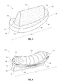
- FIG. 5 is a perspective view of the sacrum component of an exemplary artificial SI-Joint.
- FIG. 6 is a perspective view of the ilium component of an exemplary artificial SI-Joint.
- FIG. 7 is a cross-sectional view of an exemplary artificial SI-Joint.
- FIG. 8 is a cranio-caudal section view of an implanted exemplary artificial SI-Joint.
- Various aspects of the present invention relate to an artificial sacroiliac joint prosthesis.
- the artificial joint is implanted into the sacroiliac joint (SI-Joint).
- FIGS. 1-2 are, respectively, anterior and posterior views of the human hip girdle including the sacrum and the hip bones (the right ilium and the left ilium), the sacrum being connected with both hip bones at the SI-Joints.
- Each joint is encased and strengthened by two main ligaments, the interosseous (not shown) and the posterior sacroiliac ligaments (not shown).
- the ligaments allow slight movement during non-weight bearing and less movement during weight bearing movements.
- the slight movement of the SI-Joint allows the joint to have enough play to provide spinal shock absorption, enhance lower extremity torque conversions and transverse rotations.
- the spine and the lower extremities are connected by the pelvis.
- the spine movements occur in the sagittal plane and include flexion and extension.
- Hip movements may occur in all three planes, including a rotational motion which the lumbar spine does not perform well.
- the pelvic area should absorb the majority of lower extremity rotation, for example during bipedal gate.
- FIG. 3 is an enlarged lateral view of the sacrum.
- FIG. 4 is an enlarged lateral view of the sacral and lower lumbar region.
- the sacrum 2 includes an articular surface 4 that unites with the articular surface of the ilium (not shown).
- the sacroiliac articulations form the SI-Joint that is a strong synovial joint between the sacrum and the ilium.
- the SI-Joint contains numerous ridges and complimentary depressions that provide friction and help interlock the two bones.
- the sacrum is wedged anteroposteriorly allowing it to provide resistance to vertical and horizontal translation as illustrated in FIGS. 1 and 2 .
- Normal motion of the SI-Joint may include a combination of sliding, tilting and rotation.
- the SI-Joint may slide approximately 2 mm and may tilt or rotate approximately 2 to 4 degrees.
- the SI-Joint moves mostly along the sagittal plane about a point of rotation 6 and should not move
- the artificial joint may be designed to replace the SI-Joint mimicking its shape and movement.
- the artificial joint may include a sacrum component 11 and an ilium component 21 .
- FIG. 5 is a perspective view of the sacrum component of an exemplary artificial SI-Joint.
- the sacrum component 11 may include a ridge 12 , a foundation 14 , a perimeter surface 16 , and a fitting member 18 .
- the ridge 12 may be coupled to and extend away from the foundation 14 .
- the ridge 12 has a generally uniform and curved cross section in the longitudinal direction.
- ridge 12 has a bell shape cross section. Ridge 12 may include a proximal end 15 and a distal end 17 .
- the proximal end 15 and the distal end 17 of the ridge 12 may be flat and not extend to the outer edge of foundation 14 .
- Foundation 14 may include a generally flat surface that surrounds ridge 12 .
- the outer edge of foundation 14 meets an upper edge 19 of perimeter surface 16 .
- Ridge 12 , foundation 14 and fitting member 18 may be formed from a polished metal or metal alloy including, but not limited to, cobalt chromium, titanium, tantalum, tivanium (aluminum, vanadium, and titanium), stainless steel or any other joint replacement metal.
- Ridge 12 and foundation 14 may have a coating 20 that is conducive to bony in-growth, on-growth and/or through-growth.
- Coating 20 may be formed from titanium or titanium alloys.
- the coating 20 is a porous plasma spray coating.
- the coating 20 may create a biomechanically rigorous artificial joint prosthesis, designed to support acute weight bearing capacity.
- the ridge 12 and foundation 14 may be formed from a material that itself inherently possesses a structure conducive to bony in-growth, on-growth and/or through-growth, such as a porous mesh, hydroxyapatite, or other porous surface.
- the coating 20 may include a material such as a biologic aid that may promote and/or enhance bony in-growth, bony on-growth, bony through-growth, tissue repair, and/or reduce inflammation, infection and pain.
- the biologic aid may include growth factors, such as bone morphogenetic proteins (BMPs), hydroxyapatite in a liquid or slurry carrier, demineralized bone, morselized autograft or allograft bone, medications to reduce inflammation, infection and pain such as analgesics, antibiotics and steroids.
- the growth factors may be human recombinant growth factors, such as rh-BMP-2 and/or rh-BMP-7, or any other human recombinant form of BMP.
- the carrier for the biologic aid may be a liquid or gel such as saline or a collagen gel.
- the biologic aid may also be encapsulated or incorporated in a controlled released formulation so that the biologic aid is released to the patient at the implant site over a longer duration.
- the controlled release formulation may be configured to release the biologic aid over the course of days, weeks or months, and can be configured to release the biologic aid over an estimated time it would take for the implant site to heal.
- the amount of biologic aid delivered to the artificial SI-Joint may be controlled using a variety of techniques, such as controlling or varying the amount of coating material applied to the artificial SI-Joint and/or controlling or varying the amount of biologic aid incorporated into the coating material. Controlling the amount of biologic aid delivered may be important because excessive use of certain biologic aids may result in negative effects such as localized inflammation, local pain or radicular pain.
- the coating 20 may further be covered with various other coatings such as antimicrobial, antithrombotic, and osteoinductive agents, or a combination thereof.
- various other coatings such as antimicrobial, antithrombotic, and osteoinductive agents, or a combination thereof.
- the entire artificial SI-Joint may be impregnated with such agents.
- Perimeter surface 16 extends around the periphery of foundation 14 .
- the perimeter surface 16 may be flat and form a shape that compliments the fitting member 18 .
- the perimeter surface 16 forms a circumference that is bean-shaped.
- the perimeter surface 16 has a coating 20 .
- Perimeter surface 16 may be formed from similar materials as that described for ridge 12 and foundation 14 .
- Fitting member 18 may have a concave surface and an outer edge (not shown).
- the concave surface may engage a convex polybearing 22 of the ilium component 21 (see FIG. 6 ).
- the outer edge of the fitting member 18 may engage an outer edge 24 of the polybearing 22 .
- the sacrum component 11 has a length L S that extends from the proximal end 25 to the distal end 27 of sacrum component 11 .
- the length L S may be within a range of about 20 mm to 100 mm.
- the length L S may be about 20 mm, 40 mm, 60 mm, 80 mm, or 100 mm.
- FIG. 6 is a perspective view of the ilium component of an exemplary artificial SI-Joint.
- the ilium component 21 may include polybearing 22 , edge 24 , perimeter surface 26 , foundation 28 , ridge 30 and coating 32 .
- Polybearing 22 may have a bean shape.
- Polybearing 22 may be formed from one or more of a thermoplastic polyethylene (e.g. ultra-high molecular weight polyethylene, high-modulus polyethylene or high-performance polyethylene), organic polymer thermoplastic (e.g. polyether ether ketone), thermoset polymer, elastomer, pyrocarbon and other material.
- a polybearing may be located on the sacrum component 11 ( FIG. 5 ) while a metal or metal alloy bearing is located on the ilium component 21 ( FIG. 6 ).
- both the sacrum component 11 and the ilium component 21 may be made of metal or metal alloy, such as stainless steel.
- the surface of polybearing 22 may be convex and may extend away from edge 24 .
- Edge 24 may extend around the perimeter of polybearing 22 .
- Edge 24 may have a rough or treated surface designed to increase friction when engaging a surface of fitting member 18 .
- Edge 24 and polybearing 22 may engage a corresponding edge (not shown) and concave fitting member 18 , respectively, of the sacrum component 11 .
- Perimeter surface 26 may extend between the edge 24 and the rim of foundation 28 .
- the perimeter surface 26 may be flat and form a shape that is complimentary to the shape of polybearing 22 .
- the perimeter surface 26 forms a circumference that is bean shaped.
- Perimeter surface 26 may be formed from similar materials as those described with respect to perimeter surface 16 of the sacrum component 11 .
- the ridge 30 may be coupled to and extend away from the foundation 28 .
- the ridge 30 has a generally uniform and curved cross section in the longitudinal direction.
- ridge 30 has a bell shape cross section.
- Ridge 30 may include a proximal end 15 and a distal end 17 .
- the proximal end 15 and the distal end 17 of the ridge 30 may be flat and not extend to the outer edge of foundation 28 .
- Foundation 28 may include a generally flat surface that surrounds ridge 30 .
- the outer edge of foundation 28 meets an upper edge 31 of perimeter surface 26 .
- Ridge 30 and foundation 28 may be formed from similar materials as those described with respect to ridge 12 and foundation 14 of the sacrum component 11 .
- Ridge 30 and foundation 28 may have a coating 32 .
- the coating 32 may be porous. Coating 32 may be formed from similar materials as those described for coating 20 of the sacrum component 11 .
- the ilium component 21 has a length L 1 that extends from the proximal end 25 to the distal end 27 of ilium component 21 .
- the length L 1 may be within a range of about 20 mm to about 100 mm.
- the length L 1 may be about 20 mm, 40 mm, 60 mm, 80 mm, or 100 mm.
- FIG. 7 is a cross-sectional view of an exemplary artificial SI-Joint.
- the exemplary artificial SI-Joint 41 includes sacrum component 11 and ilium component 21 .
- the sacrum component 11 includes ridge 12 , coating 20 , perimeter 16 and fitting member 18 .
- Fitting member 18 has a concave shape that engages the convex shape of polybearing 22 .
- the sacrum component 11 has a height H S that extends from a first point 42 on coating 20 at the top of ridge 12 to the lower edge 23 of perimeter 16 .
- the height H S may be within a range of about 10 mm to 40 mm.
- the height H S may be about 10 mm, 15 mm, 20 mm, 25 mm, 30 mm, 35 mm or 40 mm.
- the sacrum component 11 has a width W S that extends from a first edge 38 of the perimeter surface 16 to a second edge 40 of perimeter surface 16 .
- the width of W S may be within a range of about 1 cm to 7 cm.
- the width W S may be about 1 cm, 2 cm, 3 cm, 4 cm, 5 cm, 6 cm or 7 cm.
- the ilium component 21 includes ridge 30 , coating 32 , perimeter surface 26 , and polybearing 22 .
- the ilium component 21 has a height H I that extends from a first point 44 on the coating 32 of ridge 30 to a second point 46 on polybearing 22 .
- the height of H I may be within a range of about 10 mm to 40 mm.
- the height H I may be about 10 mm, 15 mm, 20 mm, 25 mm, 30 mm, 35 mm or 40 mm.
- the ilum component 21 has a width W I that extends from a first edge 48 to a second edge 50 of the perimeter surface 26 .
- the width W 1 may be within a range of about 1 cm to 7 cm.
- the width W I may be about 1 cm, 2 cm, 3 cm, 4 cm, 5 cm, 6 cm or 7 cm.
- W S is larger than W I to allow for rotation of the artificial SI-Joint 41 .
- W S may be 7 cm and W I may be 8 cm to allow for approximately 2 to 4 degrees of rotation.
- the ilium component 21 may include a first portion and a second portion.
- the first portion may include ridge 30 , foundation 28 , perimeter surface 26 , and coating 32 .
- the second portion may include polybearing 22 .
- the first portion may also include mount 53 that fits into a notch in polybearing 22 .
- the cross section shape of mount 53 may form a knob and may extend in the longitudinal direction between the proximal end and distal end.
- the mount 53 may be formed from similar materials as described with respect to ridge 30 , foundation 28 , and perimeter surface 26 .
- FIG. 8 is a cranio-caudal section view of an implanted exemplary artificial SI-Joint.
- the artificial SI-Joint 61 includes a sacrum component having ridge 12 , foundation 14 , perimeter surface 16 , fitting member 18 , coating 20 and edge 23 .
- the artificial SI-Joint 61 also includes an ilium component having polybearing 22 , foundation 28 , and sockets 52 .
- the polybearing 22 may engage fitting member 18 which allows movement about the sacrum 2 in the sagittal plane.
- the artificial SI-Joint may move in the range of about 2 to 4 degrees.
- Sockets 52 may receive screws 54 laterally through bone of the ilium 3 .
- ridge 12 may be formed as a first piece and foundation 14 , perimeter surface 16 , and fitting member 18 may be formed as a second piece.
- foundation 28 and sockets 52 may form a third piece and polybearing 22 may form a fourth piece.
- the artificial SI-Joint like that shown in FIGS. 5-8 may be used to replace a damaged or dysfunctional SI-Joint.
- the artificial SI-Joint may be effectively implanted through the use of alternative surgical approaches; namely, a posterior inferior approach or a posterior superior approach.
- the surgical procedure is desirably aided by conventional lateral and/or anterior-posterior (A-P) visualization techniques, e.g., using X-ray image intensifiers such as a C-arms or fluoroscopes to produce a live image feed that is displayed on a TV screen.
- A-P anterior-posterior
- a physician may identify the SI-joint and the sacroiliac articulations of the SI-Joint.
- the artificial SI-Joint may be inserted along the surface of the sacroiliac articulations.
- the physician may identify where to place the pilot insertion path or bore through each of the sacrum bone segment and ilium bone segment.
- a single drill bit, multiple drill bits, reamer or other device may be employed to bore into the bone surfaces to create a pilot bore of the desired size and configuration.
- the physician may then insert the artificial SI-Joint into the bored portion of the sacrum 2 and ilium 3 .
- a curved insertion path or bore is formed in one or both of the sacrum and ilium, matching the radius of curvature of curved ridge(s) of the sacrum component and/or the ilium component.
- the radius of curvature of the ridges may be selected to match a radius of curvature of the bearing surfaces of the sacrum component and ilium component. This will allow the artificial joint to rotate about a point of rotation 6 , as shown in FIG. 3 .
- the point of rotation 6 is located outside and posterior of the body (not shown.)
- the radius of the insertion path, ridges and bearing surfaces is within the range of about 10 mm and about 70 mm. In some embodiments, it may be 100 mm. In other embodiments, the insertion path and ridges may be straight.
- the artificial SI-Joint may be inserted as a single unit into the SI-Joint with a locking pin.
- the locking pin may be removed from the artificial SI-Joint after the joint is in position.
- the artificial SI-Joint may be inserted in pieces into the bore portions of the sacrum 2 and the ilium 3 .
- ridge 12 may first be inserted into the sacrum 2 as a first piece and foundation 14 , perimeter surface 16 , and fitting member 18 may then be inserted into the sacrum 2 as a second piece coupled to the first piece.
- Foundation 28 and sockets 52 may be inserted into the ilium as a third piece and polybearing 22 may be inserted into the ilium as a fourth piece coupled to the third piece.
- the artificial SI-Joint is inserted in such a manner as to avoid excessive damage to surrounding ligaments and other tissue to maximize the effectiveness of the artificial SI-Joint.
- the insertion paths are curved as previously described, the artificial joint may be rotated into place as it is inserted along the path.
- an insertion path or bore may be formed from a lateral approach through the ilium to the sockets 52 of the artificial SI-Joint ilium component.
- the screws may be inserted through the ilium and received by the sockets 52 to secure the ilum component to the ilum.
- the artificial SI-Joint makes possible a replacement prosthetic SI-Joint.
- the design and configuration of the artificial SI-Joint mimic the normal function of an SI-Joint allowing slight movement of approximately 2 to 4 degrees.
- a surface coating for example a porous plasma spray coating with irregular surface, promotes bony in-growth, on-growth and/or through growth to provide a biomechanically rigorous prosthetic joint designed specifically to replace a dysfunctional SI-Joint and stabilize the heavily loaded lumbar spine.
- the artificial SI-Joint may be implanted as a single unit or as separate pieces that are coupled together.
Abstract
Description
Claims (11)
Priority Applications (2)
| Application Number | Priority Date | Filing Date | Title |
|---|---|---|---|
| US13/791,837 US8778026B2 (en) | 2012-03-09 | 2013-03-08 | Artificial SI joint |
| US14/332,294 US20140330382A1 (en) | 2012-03-09 | 2014-07-15 | Artificial si joint |
Applications Claiming Priority (2)
| Application Number | Priority Date | Filing Date | Title |
|---|---|---|---|
| US201261609195P | 2012-03-09 | 2012-03-09 | |
| US13/791,837 US8778026B2 (en) | 2012-03-09 | 2013-03-08 | Artificial SI joint |
Related Child Applications (1)
| Application Number | Title | Priority Date | Filing Date |
|---|---|---|---|
| US14/332,294 Continuation US20140330382A1 (en) | 2012-03-09 | 2014-07-15 | Artificial si joint |
Publications (2)
| Publication Number | Publication Date |
|---|---|
| US20130245764A1 US20130245764A1 (en) | 2013-09-19 |
| US8778026B2 true US8778026B2 (en) | 2014-07-15 |
Family
ID=49117395
Family Applications (2)
| Application Number | Title | Priority Date | Filing Date |
|---|---|---|---|
| US13/791,837 Active US8778026B2 (en) | 2012-03-09 | 2013-03-08 | Artificial SI joint |
| US14/332,294 Abandoned US20140330382A1 (en) | 2012-03-09 | 2014-07-15 | Artificial si joint |
Family Applications After (1)
| Application Number | Title | Priority Date | Filing Date |
|---|---|---|---|
| US14/332,294 Abandoned US20140330382A1 (en) | 2012-03-09 | 2014-07-15 | Artificial si joint |
Country Status (2)
| Country | Link |
|---|---|
| US (2) | US8778026B2 (en) |
| WO (1) | WO2013134682A1 (en) |
Cited By (33)
| Publication number | Priority date | Publication date | Assignee | Title |
|---|---|---|---|---|
| US9039743B2 (en) | 2004-08-09 | 2015-05-26 | Si-Bone Inc. | Systems and methods for the fusion of the sacral-iliac joint |
| WO2016044739A1 (en) * | 2014-09-18 | 2016-03-24 | Si-Bone Inc. | Matrix implant |
| WO2016044731A1 (en) * | 2014-09-18 | 2016-03-24 | Si-Bone Inc. | Implants for bone fixation or fusion |
| US9333090B2 (en) | 2010-01-13 | 2016-05-10 | Jcbd, Llc | Systems for and methods of fusing a sacroiliac joint |
| US9421109B2 (en) | 2010-01-13 | 2016-08-23 | Jcbd, Llc | Systems and methods of fusing a sacroiliac joint |
| US9554909B2 (en) | 2012-07-20 | 2017-01-31 | Jcbd, Llc | Orthopedic anchoring system and methods |
| US9675394B2 (en) | 2004-08-09 | 2017-06-13 | Si-Bone Inc. | Systems and methods for the fixation or fusion of bone at or near a sacroiliac joint |
| US9700356B2 (en) | 2013-07-30 | 2017-07-11 | Jcbd, Llc | Systems for and methods of fusing a sacroiliac joint |
| US9717539B2 (en) | 2013-07-30 | 2017-08-01 | Jcbd, Llc | Implants, systems, and methods for fusing a sacroiliac joint |
| US9757154B2 (en) | 2010-01-13 | 2017-09-12 | Jcbd, Llc | Systems and methods for fusing a sacroiliac joint and anchoring an orthopedic appliance |
| US9801546B2 (en) | 2014-05-27 | 2017-10-31 | Jcbd, Llc | Systems for and methods of diagnosing and treating a sacroiliac joint disorder |
| US9820789B2 (en) | 2004-08-09 | 2017-11-21 | Si-Bone Inc. | Systems and methods for the fixation or fusion of bone |
| US9826986B2 (en) | 2013-07-30 | 2017-11-28 | Jcbd, Llc | Systems for and methods of preparing a sacroiliac joint for fusion |
| US9839448B2 (en) | 2013-10-15 | 2017-12-12 | Si-Bone Inc. | Implant placement |
| US9949843B2 (en) | 2004-08-09 | 2018-04-24 | Si-Bone Inc. | Apparatus, systems, and methods for the fixation or fusion of bone |
| US9956013B2 (en) | 2004-08-09 | 2018-05-01 | Si-Bone Inc. | Systems and methods for the fixation or fusion of bone |
| US10045803B2 (en) | 2014-07-03 | 2018-08-14 | Mayo Foundation For Medical Education And Research | Sacroiliac joint fusion screw and method |
| US10201427B2 (en) | 2012-03-09 | 2019-02-12 | Si-Bone Inc. | Integrated implant |
| US10245087B2 (en) | 2013-03-15 | 2019-04-02 | Jcbd, Llc | Systems and methods for fusing a sacroiliac joint and anchoring an orthopedic appliance |
| US10363140B2 (en) | 2012-03-09 | 2019-07-30 | Si-Bone Inc. | Systems, device, and methods for joint fusion |
| US10376206B2 (en) | 2015-04-01 | 2019-08-13 | Si-Bone Inc. | Neuromonitoring systems and methods for bone fixation or fusion procedures |
| US10413332B2 (en) | 2016-04-25 | 2019-09-17 | Imds Llc | Joint fusion implant and methods |
| US10603177B2 (en) | 2016-04-25 | 2020-03-31 | Imds Llc | Joint fusion instrumentation and methods |
| US10603055B2 (en) | 2017-09-15 | 2020-03-31 | Jcbd, Llc | Systems for and methods of preparing and fusing a sacroiliac joint |
| US10959758B2 (en) | 2013-03-15 | 2021-03-30 | Si-Bone Inc. | Implants for spinal fixation or fusion |
| US11116519B2 (en) | 2017-09-26 | 2021-09-14 | Si-Bone Inc. | Systems and methods for decorticating the sacroiliac joint |
| US11147688B2 (en) | 2013-10-15 | 2021-10-19 | Si-Bone Inc. | Implant placement |
| US11234830B2 (en) | 2019-02-14 | 2022-02-01 | Si-Bone Inc. | Implants for spinal fixation and or fusion |
| US11291485B2 (en) | 2012-05-04 | 2022-04-05 | Si-Bone Inc. | Fenestrated implant |
| US11369419B2 (en) | 2019-02-14 | 2022-06-28 | Si-Bone Inc. | Implants for spinal fixation and or fusion |
| US11571245B2 (en) | 2019-11-27 | 2023-02-07 | Si-Bone Inc. | Bone stabilizing implants and methods of placement across SI joints |
| US11633292B2 (en) | 2005-05-24 | 2023-04-25 | Si-Bone Inc. | Apparatus, systems, and methods for the fixation or fusion of bone |
| US11752011B2 (en) | 2020-12-09 | 2023-09-12 | Si-Bone Inc. | Sacro-iliac joint stabilizing implants and methods of implantation |
Families Citing this family (6)
| Publication number | Priority date | Publication date | Assignee | Title |
|---|---|---|---|---|
| US8425570B2 (en) | 2004-08-09 | 2013-04-23 | Si-Bone Inc. | Apparatus, systems, and methods for achieving anterior lumbar interbody fusion |
| US8414648B2 (en) | 2004-08-09 | 2013-04-09 | Si-Bone Inc. | Apparatus, systems, and methods for achieving trans-iliac lumbar fusion |
| US9788961B2 (en) * | 2010-01-13 | 2017-10-17 | Jcbd, Llc | Sacroiliac joint implant system |
| US20120083883A1 (en) * | 2010-07-27 | 2012-04-05 | Ginn Richard S | System and method for sacro-iliac stabilization |
| JP6147747B2 (en) * | 2011-08-25 | 2017-06-14 | シンセス・ゲーエムベーハーSynthes GmbH | Transparent implant made of PEEK or PMMA with an uncured polymer adhesive layer |
| US9804840B2 (en) | 2013-01-23 | 2017-10-31 | International Business Machines Corporation | Vector Galois Field Multiply Sum and Accumulate instruction |
Citations (247)
| Publication number | Priority date | Publication date | Assignee | Title |
|---|---|---|---|---|
| US1951278A (en) | 1932-02-13 | 1934-03-13 | Ericsson Ernst Axel Johan | Fracture nail |
| US2136471A (en) | 1937-06-30 | 1938-11-15 | Rudolph H Schneider | Bone pin |
| US2243717A (en) | 1938-09-20 | 1941-05-27 | Moreira Franciseo Elias Godoy | Surgical device |
| US2414882A (en) | 1943-09-24 | 1947-01-28 | Herschel Leiter H | Fracture reduction apparatus |
| US2675801A (en) | 1954-04-20 | Intramedbllary nail | ||
| US3076453A (en) | 1961-01-16 | 1963-02-05 | Raymond G Tronzo | Hip nail |
| US3506982A (en) | 1965-06-21 | 1970-04-21 | Cleveland Clinic | Endoprosthetic joints |
| US3694821A (en) | 1970-11-02 | 1972-10-03 | Walter D Moritz | Artificial skeletal joint |
| US3709218A (en) | 1970-04-24 | 1973-01-09 | W Halloran | Combination intramedullary fixation and external bone compression apparatus |
| US4341206A (en) | 1978-12-19 | 1982-07-27 | Synthes Ag | Device for producing a hole in a bone |
| US4344190A (en) | 1979-07-25 | 1982-08-17 | University Of Exeter | Plugs for the medullary canal of a bone |
| US4399813A (en) | 1981-01-22 | 1983-08-23 | Barber Forest C | Apparatus and method for removing a prosthesis embedded in skeletal bone |
| US4475545A (en) | 1982-12-06 | 1984-10-09 | Ender Hans G | Bone-nail |
| US4501269A (en) | 1981-12-11 | 1985-02-26 | Washington State University Research Foundation, Inc. | Process for fusing bone joints |
| US4569338A (en) | 1984-02-09 | 1986-02-11 | Edwards Charles C | Sacral fixation device |
| US4612918A (en) | 1984-10-16 | 1986-09-23 | Barclay Slocum | Method of eliminating canine cauda equina syndrome |
| US4622959A (en) | 1985-03-05 | 1986-11-18 | Marcus Randall E | Multi-use femoral intramedullary nail |
| US4630601A (en) | 1982-05-18 | 1986-12-23 | Howmedica International, Inc. | Bone nail for the treatment of fractures |
| US4657550A (en) | 1984-12-21 | 1987-04-14 | Daher Youssef H | Buttressing device usable in a vertebral prosthesis |
| US4743256A (en) | 1985-10-04 | 1988-05-10 | Brantigan John W | Surgical prosthetic implant facilitating vertebral interbody fusion and method |
| US4773402A (en) | 1985-09-13 | 1988-09-27 | Isola Implants, Inc. | Dorsal transacral surgical implant |
| US4787378A (en) | 1986-09-08 | 1988-11-29 | Sodhi Jitendra S | Self-retaining nail for fracture of neck of femur |
| US4790303A (en) | 1987-03-11 | 1988-12-13 | Acromed Corporation | Apparatus and method for securing bone graft |
| US4834757A (en) | 1987-01-22 | 1989-05-30 | Brantigan John W | Prosthetic implant |
| US4846162A (en) | 1987-09-14 | 1989-07-11 | Moehring H David | Orthopedic nail and method of bone fracture fixation |
| US4877019A (en) | 1986-12-02 | 1989-10-31 | Pierre Vives | Intramedullary nail and apparatus for its insertion |
| US4904261A (en) | 1987-08-06 | 1990-02-27 | A. W. Showell (Surgicraft) Limited | Spinal implants |
| US4950270A (en) | 1989-02-03 | 1990-08-21 | Boehringer Mannheim Corporation | Cannulated self-tapping bone screw |
| US4961740A (en) | 1988-10-17 | 1990-10-09 | Surgical Dynamics, Inc. | V-thread fusion cage and method of fusing a bone joint |
| US5034011A (en) | 1990-08-09 | 1991-07-23 | Advanced Spine Fixation Systems Incorporated | Segmental instrumentation of the posterior spine |
| US5035697A (en) | 1990-03-20 | 1991-07-30 | Synthes (U.S.A.) | Orthopedic medullary nail |
| US5053035A (en) | 1990-05-24 | 1991-10-01 | Mclaren Alexander C | Flexible intramedullary fixation rod |
| US5066296A (en) | 1989-02-02 | 1991-11-19 | Pfizer Hopsital Products Group, Inc. | Apparatus for treating a fracture |
| US5102414A (en) | 1988-12-10 | 1992-04-07 | Imz Fertigungs-Und Vertriebsgesellschaft Fur Dentale Technologie Mbh | Implantable fixing device for extraoral applications |
| US5108397A (en) | 1990-04-19 | 1992-04-28 | Joseph White | Method and apparatus for stabilization of pelvic fractures |
| US5122141A (en) | 1990-08-30 | 1992-06-16 | Zimmer, Inc. | Modular intramedullary nail |
| US5139498A (en) | 1988-10-18 | 1992-08-18 | Astudillo Ley Freddy R | Device for closing sternum in heart surgery |
| US5147402A (en) | 1990-12-05 | 1992-09-15 | Sulzer Brothers Limited | Implant for ingrowth of osseous tissue |
| US5147367A (en) | 1991-02-22 | 1992-09-15 | Ellis Alfred B | Drill pin guide and method for orthopedic surgery |
| US5190551A (en) | 1990-12-14 | 1993-03-02 | Zimmer, Inc. | Controlled apparatus and method for extracting cement mantles from bone recesses |
| US5197961A (en) | 1992-05-12 | 1993-03-30 | Castle Tris S | Toenail extender |
| US5242444A (en) | 1991-11-04 | 1993-09-07 | University Of Florida | Lumbosacral fixation and fusion method and device |
| US5298254A (en) | 1989-09-21 | 1994-03-29 | Osteotech, Inc. | Shaped, swollen demineralized bone and its use in bone repair |
| US5334205A (en) | 1993-06-30 | 1994-08-02 | The United States Of America As Represented By The Secretary Of The Air Force | Sacroiliac joint fixation guide |
| US5443466A (en) | 1991-12-13 | 1995-08-22 | Shah; Mrugesh K. | Method and apparatus for treating fractures of a bone |
| US5470334A (en) | 1991-03-05 | 1995-11-28 | Linvatec Corporation | Bioabsorbable interference bone fixation screw |
| US5480402A (en) | 1993-08-05 | 1996-01-02 | Kim; Andrew C. | Shoulder compression interlocking system |
| US5569249A (en) | 1994-07-15 | 1996-10-29 | Smith & Nephew Richards Inc. | Cannulated modular intramedullary nail |
| US5593409A (en) | 1988-06-13 | 1997-01-14 | Sofamor Danek Group, Inc. | Interbody spinal fusion implants |
| US5609636A (en) | 1994-05-23 | 1997-03-11 | Spine-Tech, Inc. | Spinal implant |
| US5626616A (en) | 1995-05-31 | 1997-05-06 | Speece; Conrad A. | Sacroiliac joint mobilization device |
| US5645599A (en) | 1994-07-26 | 1997-07-08 | Fixano | Interspinal vertebral implant |
| US5667510A (en) | 1995-08-03 | 1997-09-16 | Combs; C. Robert | Joint fixation system and method |
| US5669909A (en) | 1995-03-27 | 1997-09-23 | Danek Medical, Inc. | Interbody fusion device and method for restoration of normal spinal anatomy |
| US5672178A (en) | 1996-01-05 | 1997-09-30 | Petersen; Thomas D. | Fixation pin |
| US5683391A (en) | 1995-06-07 | 1997-11-04 | Danek Medical, Inc. | Anterior spinal instrumentation and method for implantation and revision |
| US5713904A (en) | 1997-02-12 | 1998-02-03 | Third Millennium Engineering, Llc | Selectively expandable sacral fixation screw-sleeve device |
| US5716358A (en) | 1994-12-02 | 1998-02-10 | Johnson & Johnson Professional, Inc. | Directional bone fixation device |
| US5743912A (en) | 1995-08-23 | 1998-04-28 | Biomat | Upper femoral epiphysis osteosynthesis implant |
| US5788699A (en) | 1993-03-18 | 1998-08-04 | Endocare Ag | Drill section, as well as kirschner wires, bone routers and the like equipped with such a drill section |
| US5800440A (en) | 1997-03-18 | 1998-09-01 | Johnson & Johnson Professional, Inc. | Device for inserting a surgical pin |
| US5868749A (en) | 1996-04-05 | 1999-02-09 | Reed; Thomas M. | Fixation devices |
| US5928239A (en) | 1998-03-16 | 1999-07-27 | University Of Washington | Percutaneous surgical cavitation device and method |
| US6010507A (en) | 1998-07-24 | 2000-01-04 | Rudloff; David A. C. | Repair of bone fracture using flexible fully or partially cannulated compression/decompression fixation element |
| US6053916A (en) | 1999-02-17 | 2000-04-25 | Moore; Michael R. | Sacroiliac implant |
| US6056749A (en) | 1999-03-15 | 2000-05-02 | Spineology, Inc. | Method and device for fixing and correcting spondylolisthesis anteriorly |
| US6096080A (en) | 1998-05-06 | 2000-08-01 | Cortek, Inc. | Apparatus for spinal fusion using implanted devices |
| US6120504A (en) | 1998-12-10 | 2000-09-19 | Biomet Inc. | Intramedullary nail having dual distal bore formation |
| US6143031A (en) | 1995-10-20 | 2000-11-07 | Synthes (U.S.A.) | Intervertebral implant with compressible shaped hollow element |
| US6210442B1 (en) | 1996-07-15 | 2001-04-03 | Aesculap Ag & Co. Kg | Implant for vertebral body fusion |
| US6214049B1 (en) | 1999-01-14 | 2001-04-10 | Comfort Biomedical, Inc. | Method and apparatus for augmentating osteointegration of prosthetic implant devices |
| US6221074B1 (en) | 1999-06-10 | 2001-04-24 | Orthodyne, Inc. | Femoral intramedullary rod system |
| US6224607B1 (en) | 1999-01-25 | 2001-05-01 | Gary K. Michelson | Instrumentation and method for creating an intervertebral space for receiving an implant |
| US6241732B1 (en) | 1998-11-03 | 2001-06-05 | David W. Overaker | Biocompatible absorbable rivets and pins for use in surgical procedures |
| US6270528B1 (en) | 1998-08-06 | 2001-08-07 | Sdgi Holdings, Inc. | Composited intervertebral bone spacers |
| US6302885B1 (en) | 1998-01-15 | 2001-10-16 | Holger K. Essiger | Bone nail |
| US6302914B1 (en) | 1995-06-07 | 2001-10-16 | Gary Karlin Michelson | Lordotic interbody spinal fusion implants |
| US6306140B1 (en) | 2001-01-17 | 2001-10-23 | Synthes (Usa) | Bone screw |
| US6319253B1 (en) | 1998-03-05 | 2001-11-20 | Synthes (U.S.A) | Intramedullary nail with locking hole |
| US20010047207A1 (en) | 1998-10-30 | 2001-11-29 | Michelson Gary K. | Self-broaching, rotatable, push-in interbody spinal fusion implant and method for deployment thereof |
| US20010046518A1 (en) | 1998-08-14 | 2001-11-29 | Amarpreet S. Sawhney | Methods of using in situ hydration of hydrogel articles for sealing or augmentation of tissue or vessels |
| US20010049529A1 (en) | 1996-11-12 | 2001-12-06 | Cachia Victor V. | Bone fixation system |
| US20020038123A1 (en) | 2000-09-20 | 2002-03-28 | Visotsky Jeffrey L. | Osteotomy implant |
| US20020049497A1 (en) | 2000-10-11 | 2002-04-25 | Mason Michael D. | Graftless spinal fusion device |
| US6409768B1 (en) | 2000-03-16 | 2002-06-25 | Slobodan Tepic | Screw anchored joint prosthesis |
| US20020120275A1 (en) | 2001-02-26 | 2002-08-29 | Arthrex, Inc. | Torque driver for interference screw |
| US20020128652A1 (en) | 1999-12-03 | 2002-09-12 | Ferree Bret A. | Version with markings to show changes made |
| US6451020B1 (en) | 1997-01-02 | 2002-09-17 | St. Francis Medical Technologies, Inc. | Spine distraction implant and method |
| US20020143335A1 (en) | 2001-03-30 | 2002-10-03 | Von Hoffmann Gerard | Distal bone anchors for bone fixation with secondary compression |
| US20020151903A1 (en) | 2001-04-12 | 2002-10-17 | Asahi Kogaku Kogyo Kabushiki Kaisha | Surgical instrument |
| US6471707B1 (en) | 2001-05-11 | 2002-10-29 | Biomet | Bone screw having bioresorbable proximal shaft portion |
| US6485518B1 (en) | 1999-12-10 | 2002-11-26 | Nuvasive | Facet screw and bone allograft intervertebral support and fusion system |
| US20020183858A1 (en) | 2001-06-05 | 2002-12-05 | Contiliano Joseph H. | Attachment of absorbable tissue scaffolds to scaffold fixation devices |
| US6497707B1 (en) | 1999-07-23 | 2002-12-24 | Ethicon, Inc. | Graft fixation device combination |
| US20020198527A1 (en) | 2001-06-21 | 2002-12-26 | Helmut Muckter | Implantable screw for stabilization of a joint or a bone fracture |
| US20030018336A1 (en) | 2001-07-17 | 2003-01-23 | Mark Vandewalle | Intramedullary nail with modular sleeve |
| WO2003007839A2 (en) | 2001-07-16 | 2003-01-30 | Depuy Products, Inc. | Devices form naturally occurring biologically derived |
| US6517541B1 (en) | 1998-12-23 | 2003-02-11 | Nenad Sesic | Axial intramedullary screw for the osteosynthesis of long bones |
| US6520969B2 (en) | 1997-12-19 | 2003-02-18 | Stryker Technologies Corporation | Guide-pin placement device |
| US6524314B1 (en) | 2001-08-24 | 2003-02-25 | John C. Dean | Interlocking intramedullary nail |
| EP1287796A1 (en) | 2001-09-04 | 2003-03-05 | Biorthex Inc. | Intervertebral fusion device |
| US20030065332A1 (en) | 2001-09-28 | 2003-04-03 | Ethicon, Inc. | Self-tapping resorbable two-piece bone screw |
| US20030074000A1 (en) | 2001-10-17 | 2003-04-17 | Roth Christoph Andreas | Bone fixation system |
| US20030083688A1 (en) | 2001-10-30 | 2003-05-01 | Simonson Robert E. | Configured and sized cannula |
| US6565566B1 (en) | 2000-03-22 | 2003-05-20 | Spinal Concepts, Inc. | Sacral screw assembly and method |
| US20030097131A1 (en) | 2001-11-16 | 2003-05-22 | Schon Lew C. | Modular, blade-rod, intramedullary fixation device |
| US6575991B1 (en) | 1999-06-17 | 2003-06-10 | Inrad, Inc. | Apparatus for the percutaneous marking of a lesion |
| US6575899B1 (en) | 1999-10-20 | 2003-06-10 | Sdgi Holdings, Inc. | Methods and instruments for endoscopic interbody surgical techniques |
| US6579293B1 (en) | 2000-08-02 | 2003-06-17 | Rama E. Chandran | Intramedullary rod with interlocking oblique screw for tibio-calcaneal arthrodesis |
| US6582431B1 (en) | 1997-02-06 | 2003-06-24 | Howmedica Osteonics Corp. | Expandable non-threaded spinal fusion device |
| US6595998B2 (en) | 2001-03-08 | 2003-07-22 | Spinewave, Inc. | Tissue distraction device |
| US6602293B1 (en) | 1996-11-01 | 2003-08-05 | The Johns Hopkins University | Polymeric composite orthopedic implant |
| US6605090B1 (en) | 2000-10-25 | 2003-08-12 | Sdgi Holdings, Inc. | Non-metallic implant devices and intra-operative methods for assembly and fixation |
| US6607530B1 (en) | 1999-05-10 | 2003-08-19 | Highgate Orthopedics, Inc. | Systems and methods for spinal fixation |
| US6635059B2 (en) | 2001-01-03 | 2003-10-21 | Bernard L. Randall | Cannulated locking screw system especially for transiliac implant |
| US20030199983A1 (en) | 1999-05-05 | 2003-10-23 | Michelson Gary K. | Interbody spinal fusion implants with end cap for locking vertebral body penetrating members |
| US20030233147A1 (en) | 1998-05-06 | 2003-12-18 | Nicholson James E. | Device for spinal fusion |
| US6666868B2 (en) | 2001-03-02 | 2003-12-23 | Medicinelodge, Inc. | Two-part orthopedic fastener |
| US6669529B1 (en) | 2003-02-25 | 2003-12-30 | Joseph L. Scaries | Turkey call |
| US6673075B2 (en) | 2001-02-23 | 2004-01-06 | Albert N. Santilli | Porous intervertebral spacer |
| WO2004002344A1 (en) | 2002-06-26 | 2004-01-08 | Synthes Ag Chur | Bone fixing element |
| US20040024458A1 (en) | 2000-12-22 | 2004-02-05 | Jacques Senegas | Intervertebral implant with deformable wedge |
| US6692501B2 (en) | 2000-12-14 | 2004-02-17 | Gary K. Michelson | Spinal interspace shaper |
| US20040073314A1 (en) | 2002-03-21 | 2004-04-15 | White John L. | Vertebral body and disc space replacement devices |
| US20040073216A1 (en) | 2000-10-05 | 2004-04-15 | The Cleveland Clinic Foundation | Apparatus and method for attaching adjacent bones |
| US6723099B1 (en) | 2001-11-08 | 2004-04-20 | Biomet, Inc. | Three sided tack for bone fixation |
| JP2004512895A (en) | 2000-11-10 | 2004-04-30 | ビーダーマン・モテーク・ゲゼルシャフト・ミット・ベシュレンクタ・ハフツング | Bone screw |
| US20040087948A1 (en) | 2002-08-29 | 2004-05-06 | Loubert Suddaby | Spinal facet fixation device |
| US6740118B2 (en) * | 2002-01-09 | 2004-05-25 | Sdgi Holdings, Inc. | Intervertebral prosthetic joint |
| US6743257B2 (en) | 2000-12-19 | 2004-06-01 | Cortek, Inc. | Dynamic implanted intervertebral spacer |
| US20040106925A1 (en) | 2002-11-25 | 2004-06-03 | Culbert Brad S. | Soft tissue anchor and method of using same |
| US20040117022A1 (en) | 2002-12-13 | 2004-06-17 | Theirry Marnay | Intervertebral implant, insertion tool and method of inserting same |
| US20040127990A1 (en) | 2002-12-31 | 2004-07-01 | Bartish, Charles M. | Novel banana cage |
| US20040147929A1 (en) | 2002-12-20 | 2004-07-29 | Biedermann Motech Gmbh | Tubular element for an implant for use in spine or bone surgery and implant having such an element |
| US20040181282A1 (en) | 2002-10-29 | 2004-09-16 | Zucherman James F. | Interspinous process apparatus and method with a selectably expandable spacer |
| US20040225360A1 (en) | 2000-12-14 | 2004-11-11 | Malone David G. | Devices and methods for facilitating controlled bone growth or repair |
| US20050033435A1 (en) | 2003-08-04 | 2005-02-10 | Spine Next | Intervertebral disk prosthesis |
| US20050049590A1 (en) | 2003-03-07 | 2005-03-03 | Neville Alleyne | Spinal implant with securement spikes |
| US20050055023A1 (en) | 2002-07-23 | 2005-03-10 | Advanced Orthopaedic Solutions, Inc. | Intramedullary nail for long bone fractures |
| US20050107878A1 (en) | 2000-12-05 | 2005-05-19 | Stryker Spine | Spinal intervertebral implant adjustable in situ |
| US20050124993A1 (en) | 2002-12-02 | 2005-06-09 | Chappuis James L. | Facet fusion system |
| US20050137605A1 (en) | 2003-10-23 | 2005-06-23 | Assell Robert L. | Guide pin for guiding instrumentation along a soft tissue tract to a point on the spine |
| US20050159749A1 (en) | 2004-01-16 | 2005-07-21 | Expanding Orthopedics, Inc. | Bone fracture treatment devices and methods of their use |
| US20050165398A1 (en) | 2004-01-26 | 2005-07-28 | Reiley Mark A. | Percutaneous spine distraction implant systems and methods |
| US20050228384A1 (en) | 1997-01-02 | 2005-10-13 | St. Francis Medical Technologies, Inc. | Spinous process implant with tethers |
| US20050246021A1 (en) | 2004-04-29 | 2005-11-03 | Ringeisen Timothy A | Compressed porous materials suitable for implant |
| WO2006003316A1 (en) | 2004-06-11 | 2006-01-12 | Perception Raisonnement Action En Medecine | Pin for attaching a support member to a bone |
| US20060036247A1 (en) | 1993-06-10 | 2006-02-16 | Karlin Technology, Inc. | Distractor for use in spinal surgery |
| US20060036251A1 (en) | 2004-08-09 | 2006-02-16 | Reiley Mark A | Systems and methods for the fixation or fusion of bone |
| US20060054171A1 (en) | 2004-09-15 | 2006-03-16 | Bruce Dall | Method and apparatus of approaching a joint |
| US20060084986A1 (en) | 2004-09-30 | 2006-04-20 | Depuy Spine, Inc. | Instrument and method for the insertion and alignment of an intervertebral implant |
| US20060111779A1 (en) | 2004-11-22 | 2006-05-25 | Orthopedic Development Corporation, A Florida Corporation | Minimally invasive facet joint fusion |
| US20060129247A1 (en) | 1993-11-01 | 2006-06-15 | Bioment Manufacturing Corp. | Intramedullary compliant fixation |
| US20060161163A1 (en) | 2003-07-11 | 2006-07-20 | Konsei Shino | Instrument for reconstructing ligament and method of reconstructing ligament |
| US7118579B2 (en) | 2001-02-04 | 2006-10-10 | Sdgi Holdings, Inc. | Instrumentation for inserting an expandable interbody spinal fusion implant |
| US20060241776A1 (en) | 2005-04-21 | 2006-10-26 | Biomet Manufacturing Corp. | Method and apparatus for use of porous implants |
| US20060293662A1 (en) | 2005-06-13 | 2006-12-28 | Boyer Michael L Ii | Spinous process spacer |
| US7175663B1 (en) | 2003-10-08 | 2007-02-13 | Biomet Manufacturing Corp. | Shoulder implant assembly |
| US20070088362A1 (en) | 2004-10-26 | 2007-04-19 | Bonutti,Ip, Llc | Apparatus and methods for surgery |
| US20070093841A1 (en) | 2005-09-23 | 2007-04-26 | Thomas Hoogland | Surgical drill, a set of surgical drills, a system for cutting bone and a method for removing bone |
| US7211085B2 (en) | 2001-03-01 | 2007-05-01 | Warsaw Orthopedic, Inc. | Dynamic lordotic guard with movable extensions for creating an implantation space posteriorly in the lumbar spine and method for use thereof |
| US7223269B2 (en) | 2002-12-02 | 2007-05-29 | Chappuis James L | Facet fusion system |
| US20070149976A1 (en) | 2003-08-29 | 2007-06-28 | Gerraspine A.G. | Method for resurfacing a lumbar articular facet |
| US20070156241A1 (en) | 2004-08-09 | 2007-07-05 | Reiley Mark A | Systems and methods for the fixation or fusion of bone |
| US20070156246A1 (en) | 2003-08-29 | 2007-07-05 | Meswania Jayantilal M | Shoulder joint prosthetic system |
| US20070161989A1 (en) | 2005-12-20 | 2007-07-12 | Sdgi Holdings, Inc. | Vertebral implant inserter and method of use |
| US20070233146A1 (en) | 2006-01-27 | 2007-10-04 | Stryker Corporation | Low pressure delivery system and method for delivering a solid and liquid mixture into a target site for medical treatment |
| US20070250166A1 (en) | 2006-04-25 | 2007-10-25 | Sdgi Holdings, Inc. | Facet fusion implants and methods of use |
| US20070270879A1 (en) | 2006-04-19 | 2007-11-22 | Depuy Spine, Inc. | Sacroiliac joint fusion alignment guide |
| US20080021455A1 (en) | 2006-07-21 | 2008-01-24 | Depuy Spine, Inc. | Articulating Sacral or Iliac Connector |
| US20080021456A1 (en) | 2006-07-21 | 2008-01-24 | Depuy Spine, Inc. | Sacral or iliac cross connector |
| US20080021454A1 (en) | 2006-07-21 | 2008-01-24 | Depuy Spine, Inc. | Sacral or iliac connector |
| US20080021461A1 (en) | 2006-07-24 | 2008-01-24 | Warsaw Orthopedic Inc. | Spinal stabilization and reconstruction with fusion rods |
| US7335205B2 (en) | 2001-03-02 | 2008-02-26 | Woodwelding Ag | Implants, device and method for joining tissue parts |
| US20080154374A1 (en) | 2006-12-20 | 2008-06-26 | Robert David Labrom | Joint implant and a surgical method associated therewith |
| US20080161810A1 (en) | 2006-10-18 | 2008-07-03 | Warsaw Orthopedic, Inc. | Guide and Cutter for Contouring Facet Joints and Methods of Use |
| US20080234758A1 (en) | 2007-02-26 | 2008-09-25 | Depuy Spine, Inc. | Intra-facet fixation device and method of use |
| US20080255666A1 (en) | 2007-04-13 | 2008-10-16 | Depuy Spine, Inc. | Facet fixation and fusion wedge and method of use |
| US20080255664A1 (en) | 2007-04-10 | 2008-10-16 | Mdesign International | Percutaneously deliverable orthopedic joint device |
| US20080255622A1 (en) | 2007-04-13 | 2008-10-16 | Depuy Spine, Inc. | Facet fixation and fusion screw and washer assembly and method of use |
| US20080255667A1 (en) | 2007-04-13 | 2008-10-16 | Horton Kenneth L | Allograft spinal facet fusion system |
| US20080255618A1 (en) | 2007-04-13 | 2008-10-16 | Depuy Spine, Inc. | Articulating facet fusion screw |
| US20080275454A1 (en) | 2007-05-04 | 2008-11-06 | Geibel Paul T | Lumbar pedicular-facet fixation system and instrumentation |
| US7452369B2 (en) | 2004-10-18 | 2008-11-18 | Barry Richard J | Spine microsurgery techniques, training aids and implants |
| US7452359B1 (en) | 1988-06-13 | 2008-11-18 | Warsaw Orthopedic, Inc. | Apparatus for inserting spinal implants |
| US20080306554A1 (en) | 2007-06-11 | 2008-12-11 | Mckinley Laurence M | Osseointegration and biointegration coatings for bone screw implants |
| US20090018660A1 (en) * | 2007-07-13 | 2009-01-15 | Roush Thomas F | Hybrid fusion/arthroplasty device |
| US20090024174A1 (en) | 2007-07-17 | 2009-01-22 | Stark John G | Bone screws and particular applications to sacroiliac joint fusion |
| US7481831B2 (en) | 1999-08-09 | 2009-01-27 | Marctec, Llc. | Method of securing tissue |
| US20090036927A1 (en) | 2007-05-22 | 2009-02-05 | Tov Vestgaarden | Method and apparatus for spinal facet fusion |
| US20090043393A1 (en) * | 2004-06-30 | 2009-02-12 | Synergy Disc Replacement, Inc. | Artificial Spinal Disc |
| US20090099602A1 (en) | 2007-09-11 | 2009-04-16 | Kamran Aflatoon | Method of lateral facet approach, decompression and fusion using screws and staples as well as arthroplasty |
| US20090099610A1 (en) | 2007-10-12 | 2009-04-16 | Donald Johnson | Methods of stabilizing the sacroiliac joint |
| US7534254B1 (en) | 1988-06-13 | 2009-05-19 | Warsaw Orthopedic, Inc. | Threaded frusto-conical interbody spinal fusion implants |
| US20090131986A1 (en) | 2007-11-19 | 2009-05-21 | David Lee | Method and apparatus for spinal facet joint fusion using irregularly shaped cortical bone implants |
| US20090138053A1 (en) | 2007-09-25 | 2009-05-28 | Zyga Technology, Inc. | Method and apparatus for facet joint stabilization |
| US20090157119A1 (en) | 2007-10-29 | 2009-06-18 | Horace Winston Hale | Orthopedic fixation mechanism |
| US20090163920A1 (en) | 2007-07-03 | 2009-06-25 | Stephen Hochschuler | Facet fusion implant |
| US20090187247A1 (en) | 2008-01-23 | 2009-07-23 | Metcalf Jr Newton H | Spinal implant having a resorbable anchor device for temporarily securing an interbody device to adjacent upper and lower vertebrae |
| US7569054B2 (en) | 1988-06-13 | 2009-08-04 | Warsaw Orthopedic, Inc. | Tubular member having a passage and opposed bone contacting extensions |
| US20090216238A1 (en) | 2008-02-27 | 2009-08-27 | Stark John G | Tools for performing less invasive orthopedic joint procedures |
| US20090259261A1 (en) | 2004-08-09 | 2009-10-15 | Mark A Reiley | Systems and methods for the fixation or fusion of bone at or near a sacroiliac joint |
| US20090270929A1 (en) | 2008-04-24 | 2009-10-29 | Loubert Suddaby | Facet joint fixation device |
| US20090287254A1 (en) | 2008-05-13 | 2009-11-19 | Warsaw Orthopedic, Inc. | Ilio-Sacral Connector System and Method |
| US20090312798A1 (en) | 2008-06-16 | 2009-12-17 | Armando Varela | Transfacet fixation assembly and related surgical methods |
| US7648509B2 (en) | 2003-03-10 | 2010-01-19 | Ilion Medical Llc | Sacroiliac joint immobilization |
| US7686805B2 (en) | 1988-06-13 | 2010-03-30 | Warsaw Orthopedic, Inc. | Methods for distraction of a disc space |
| US20100094290A1 (en) | 2008-10-09 | 2010-04-15 | Rahul Vaidya | Method for minimally invasive treatment of unstable pelvic ring injuries with an internal anterior fixator and posterior lliosacral screws |
| US7699852B2 (en) | 2003-11-19 | 2010-04-20 | Zimmer Spine, Inc. | Fenestrated bone tap and method |
| US20100106195A1 (en) | 2005-03-24 | 2010-04-29 | Depuy Spine, Inc. | Low profile spinal tethering methods |
| US20100114174A1 (en) | 2008-10-30 | 2010-05-06 | Bryan Jones | Systems and Methods for Delivering Bone Cement to a Bone Anchor |
| US20100114317A1 (en) | 2007-09-07 | 2010-05-06 | Intrinsic Therapeutics, Inc. | Impaction grafting for vertebral fusion |
| US20100145461A1 (en) | 2002-03-11 | 2010-06-10 | Landry Michael E | Instrumentation and procedure for implanting spinal implant devices |
| US7758646B2 (en) * | 2002-12-17 | 2010-07-20 | Amedica Corporation | Total disc implant |
| US20100191292A1 (en) | 2004-02-17 | 2010-07-29 | Demeo Joseph | Oriented polymer implantable device and process for making same |
| WO2010105196A1 (en) | 2009-03-13 | 2010-09-16 | University Of Toledo | Removable anchoring pedicle screw |
| US20100268228A1 (en) | 2009-03-20 | 2010-10-21 | Minsurg International, Inc. | Surgical methods and tools |
| US20100280622A1 (en) | 2004-09-14 | 2010-11-04 | Aeolin, Llc | System and method for spinal fusion |
| US20100286778A1 (en) | 2007-04-18 | 2010-11-11 | Lukas Eisermann | Textile-Based Spinal Implant and Related Methods |
| US7850732B2 (en) | 2006-12-11 | 2010-12-14 | Warsaw Orthopedic, Inc. | Sacral prosthesis and surgical method |
| US7857832B2 (en) | 2004-12-08 | 2010-12-28 | Interventional Spine, Inc. | Method and apparatus for spinal stabilization |
| US20100331893A1 (en) | 2009-06-26 | 2010-12-30 | Wyatt Drake Geist | K-Wire And Method For Surgical Procedures |
| US20110009869A1 (en) | 2009-05-11 | 2011-01-13 | Marino James F | Transiliac-transsacral method of performing lumbar spinal interventions |
| US20110022089A1 (en) | 2009-07-24 | 2011-01-27 | Zyga Technology, Inc | Systems and methods for facet joint treatment |
| US20110040362A1 (en) | 2004-11-15 | 2011-02-17 | Neil Godara | Methods of Treating the Sacroiliac Region of a Patient's Body |
| US20110046737A1 (en) | 2009-08-19 | 2011-02-24 | Jacques Teisen | Method and apparatus for augmenting bone |
| US7909832B2 (en) | 2001-03-01 | 2011-03-22 | Warsaw Orthopedic, Inc. | Retractor for percutaneous surgery in a patient and method for use thereof |
| US20110087294A1 (en) | 2004-08-09 | 2011-04-14 | SI Bone, Inc. | Systems and methods for the fusion of the sacral-iliac joint |
| US7942879B2 (en) | 2003-12-30 | 2011-05-17 | Depuy Products, Inc. | Minimally invasive bone miller apparatus |
| US20110184519A1 (en) | 2010-01-26 | 2011-07-28 | Warsaw Orthopedic, Inc. | Sacro-iliac joint implant system, method and instrument |
| US20110184520A1 (en) | 2010-01-27 | 2011-07-28 | Warsaw Orthopedic, Inc. | Sacro-iliac joint implant, method and apparatus |
| US20110184518A1 (en) | 2010-01-22 | 2011-07-28 | Warsaw Orthopedic, Inc. | Sacro-iliac joint implant |
| WO2011110865A2 (en) * | 2010-03-11 | 2011-09-15 | Biomet Ltd | Tibial prosthetic component for a partial or unicondylar bearing knee replacement, method of selecting such a tibial prosthetic component, method of implanting such a tibial prosthetic component and a kit for a surgeon |
| US20110230966A1 (en) | 2010-03-18 | 2011-09-22 | Warsaw Orthopedic, Inc. | Sacro-iliac implant system, method and apparatus |
| US20110238181A1 (en) | 2010-03-29 | 2011-09-29 | Warsaw Orthopedic, Inc., A Indiana Corporation | Sacro-iliac joint implant system and method |
| US20110257755A1 (en) | 2009-01-08 | 2011-10-20 | Philippe Bellemere | Orthopaedic implant for arthroplasty of the fingers |
| US20110264229A1 (en) | 2010-01-13 | 2011-10-27 | Jcbd, Llc | Sacroiliac joint fixation system |
| US8066709B2 (en) | 1996-07-31 | 2011-11-29 | Warsaw Orthopedic, Inc. | Distractor with opening |
| US8066705B2 (en) | 1988-06-13 | 2011-11-29 | Warsaw Orthopedic, Inc. | Instrumentation for the endoscopic correction of spinal disease |
| US20130053902A1 (en) | 2011-08-24 | 2013-02-28 | Jeffrey L. Trudeau | Apparatus and methods for immobilization and fusion of a synovial joint |
| US8414648B2 (en) | 2004-08-09 | 2013-04-09 | Si-Bone Inc. | Apparatus, systems, and methods for achieving trans-iliac lumbar fusion |
| US8425570B2 (en) | 2004-08-09 | 2013-04-23 | Si-Bone Inc. | Apparatus, systems, and methods for achieving anterior lumbar interbody fusion |
| US8444693B2 (en) | 2004-08-09 | 2013-05-21 | Si-Bone Inc. | Apparatus, systems, and methods for achieving lumbar facet fusion |
| US8470004B2 (en) | 2004-08-09 | 2013-06-25 | Si-Bone Inc. | Apparatus, systems, and methods for stabilizing a spondylolisthesis |
| US20130218215A1 (en) | 2010-07-27 | 2013-08-22 | Tenon Medical, Inc. | Method for sacro-iliac stabilization |
| US20130245703A1 (en) | 2012-03-02 | 2013-09-19 | Interventional Spine, Inc. | Method and apparatus for sacroiliac joint fixation |
| US8672986B2 (en) | 2003-04-10 | 2014-03-18 | DePuy Synthes Products, LLC | Device for temporarily splinting toes |
Family Cites Families (9)
| Publication number | Priority date | Publication date | Assignee | Title |
|---|---|---|---|---|
| US20040260286A1 (en) * | 1999-10-08 | 2004-12-23 | Ferree Bret A. | Intradiscal devices with anti-extrusion keels |
| US7235081B2 (en) * | 2001-07-16 | 2007-06-26 | Spinecore, Inc. | Wedge plate inserter/impactor and related methods for use in implanting an artificial intervertebral disc |
| US6989032B2 (en) * | 2001-07-16 | 2006-01-24 | Spinecore, Inc. | Artificial intervertebral disc |
| FR2832054B1 (en) * | 2001-11-15 | 2004-09-10 | Rene Louis | POSTERIOR VERTEBRAL JOINT PROSTHESIS |
| US8696749B2 (en) * | 2002-04-25 | 2014-04-15 | Blackstone Medical, Inc. | Artificial intervertebral disc |
| US6770095B2 (en) * | 2002-06-18 | 2004-08-03 | Depuy Acroned, Inc. | Intervertebral disc |
| US6966929B2 (en) * | 2002-10-29 | 2005-11-22 | St. Francis Medical Technologies, Inc. | Artificial vertebral disk replacement implant with a spacer |
| US7048764B2 (en) * | 2003-01-07 | 2006-05-23 | Ferree Bret A | Artificial disc replacements with articulating components |
| US20090082869A1 (en) * | 2007-09-14 | 2009-03-26 | Slemker Tracy C | Double ended pyramid adapter |
-
2013
- 2013-03-08 US US13/791,837 patent/US8778026B2/en active Active
- 2013-03-08 WO PCT/US2013/029950 patent/WO2013134682A1/en active Application Filing
-
2014
- 2014-07-15 US US14/332,294 patent/US20140330382A1/en not_active Abandoned
Patent Citations (268)
| Publication number | Priority date | Publication date | Assignee | Title |
|---|---|---|---|---|
| US2675801A (en) | 1954-04-20 | Intramedbllary nail | ||
| US1951278A (en) | 1932-02-13 | 1934-03-13 | Ericsson Ernst Axel Johan | Fracture nail |
| US2136471A (en) | 1937-06-30 | 1938-11-15 | Rudolph H Schneider | Bone pin |
| US2243717A (en) | 1938-09-20 | 1941-05-27 | Moreira Franciseo Elias Godoy | Surgical device |
| US2414882A (en) | 1943-09-24 | 1947-01-28 | Herschel Leiter H | Fracture reduction apparatus |
| US3076453A (en) | 1961-01-16 | 1963-02-05 | Raymond G Tronzo | Hip nail |
| US3506982A (en) | 1965-06-21 | 1970-04-21 | Cleveland Clinic | Endoprosthetic joints |
| US3709218A (en) | 1970-04-24 | 1973-01-09 | W Halloran | Combination intramedullary fixation and external bone compression apparatus |
| US3694821A (en) | 1970-11-02 | 1972-10-03 | Walter D Moritz | Artificial skeletal joint |
| US4341206A (en) | 1978-12-19 | 1982-07-27 | Synthes Ag | Device for producing a hole in a bone |
| US4344190A (en) | 1979-07-25 | 1982-08-17 | University Of Exeter | Plugs for the medullary canal of a bone |
| US4399813A (en) | 1981-01-22 | 1983-08-23 | Barber Forest C | Apparatus and method for removing a prosthesis embedded in skeletal bone |
| US4501269A (en) | 1981-12-11 | 1985-02-26 | Washington State University Research Foundation, Inc. | Process for fusing bone joints |
| US4630601A (en) | 1982-05-18 | 1986-12-23 | Howmedica International, Inc. | Bone nail for the treatment of fractures |
| US4475545A (en) | 1982-12-06 | 1984-10-09 | Ender Hans G | Bone-nail |
| US4569338A (en) | 1984-02-09 | 1986-02-11 | Edwards Charles C | Sacral fixation device |
| US4612918A (en) | 1984-10-16 | 1986-09-23 | Barclay Slocum | Method of eliminating canine cauda equina syndrome |
| US4657550A (en) | 1984-12-21 | 1987-04-14 | Daher Youssef H | Buttressing device usable in a vertebral prosthesis |
| US4622959A (en) | 1985-03-05 | 1986-11-18 | Marcus Randall E | Multi-use femoral intramedullary nail |
| US4773402A (en) | 1985-09-13 | 1988-09-27 | Isola Implants, Inc. | Dorsal transacral surgical implant |
| US4743256A (en) | 1985-10-04 | 1988-05-10 | Brantigan John W | Surgical prosthetic implant facilitating vertebral interbody fusion and method |
| US4787378A (en) | 1986-09-08 | 1988-11-29 | Sodhi Jitendra S | Self-retaining nail for fracture of neck of femur |
| US4877019A (en) | 1986-12-02 | 1989-10-31 | Pierre Vives | Intramedullary nail and apparatus for its insertion |
| US4834757A (en) | 1987-01-22 | 1989-05-30 | Brantigan John W | Prosthetic implant |
| US4878915A (en) | 1987-01-22 | 1989-11-07 | Brantigan John W | Surgical prosthetic implant facilitating vertebral interbody fusion |
| US4790303A (en) | 1987-03-11 | 1988-12-13 | Acromed Corporation | Apparatus and method for securing bone graft |
| US4904261A (en) | 1987-08-06 | 1990-02-27 | A. W. Showell (Surgicraft) Limited | Spinal implants |
| US4846162A (en) | 1987-09-14 | 1989-07-11 | Moehring H David | Orthopedic nail and method of bone fracture fixation |
| US8066705B2 (en) | 1988-06-13 | 2011-11-29 | Warsaw Orthopedic, Inc. | Instrumentation for the endoscopic correction of spinal disease |
| US7686805B2 (en) | 1988-06-13 | 2010-03-30 | Warsaw Orthopedic, Inc. | Methods for distraction of a disc space |
| US7569054B2 (en) | 1988-06-13 | 2009-08-04 | Warsaw Orthopedic, Inc. | Tubular member having a passage and opposed bone contacting extensions |
| US7534254B1 (en) | 1988-06-13 | 2009-05-19 | Warsaw Orthopedic, Inc. | Threaded frusto-conical interbody spinal fusion implants |
| US7452359B1 (en) | 1988-06-13 | 2008-11-18 | Warsaw Orthopedic, Inc. | Apparatus for inserting spinal implants |
| US5593409A (en) | 1988-06-13 | 1997-01-14 | Sofamor Danek Group, Inc. | Interbody spinal fusion implants |
| US4961740A (en) | 1988-10-17 | 1990-10-09 | Surgical Dynamics, Inc. | V-thread fusion cage and method of fusing a bone joint |
| US4961740B1 (en) | 1988-10-17 | 1997-01-14 | Surgical Dynamics Inc | V-thread fusion cage and method of fusing a bone joint |
| US5139498A (en) | 1988-10-18 | 1992-08-18 | Astudillo Ley Freddy R | Device for closing sternum in heart surgery |
| US5102414A (en) | 1988-12-10 | 1992-04-07 | Imz Fertigungs-Und Vertriebsgesellschaft Fur Dentale Technologie Mbh | Implantable fixing device for extraoral applications |
| US5066296A (en) | 1989-02-02 | 1991-11-19 | Pfizer Hopsital Products Group, Inc. | Apparatus for treating a fracture |
| US4950270A (en) | 1989-02-03 | 1990-08-21 | Boehringer Mannheim Corporation | Cannulated self-tapping bone screw |
| US5298254A (en) | 1989-09-21 | 1994-03-29 | Osteotech, Inc. | Shaped, swollen demineralized bone and its use in bone repair |
| US5035697A (en) | 1990-03-20 | 1991-07-30 | Synthes (U.S.A.) | Orthopedic medullary nail |
| US5108397A (en) | 1990-04-19 | 1992-04-28 | Joseph White | Method and apparatus for stabilization of pelvic fractures |
| US5053035A (en) | 1990-05-24 | 1991-10-01 | Mclaren Alexander C | Flexible intramedullary fixation rod |
| US5034011A (en) | 1990-08-09 | 1991-07-23 | Advanced Spine Fixation Systems Incorporated | Segmental instrumentation of the posterior spine |
| US5122141A (en) | 1990-08-30 | 1992-06-16 | Zimmer, Inc. | Modular intramedullary nail |
| US5147402A (en) | 1990-12-05 | 1992-09-15 | Sulzer Brothers Limited | Implant for ingrowth of osseous tissue |
| US5190551A (en) | 1990-12-14 | 1993-03-02 | Zimmer, Inc. | Controlled apparatus and method for extracting cement mantles from bone recesses |
| US5147367A (en) | 1991-02-22 | 1992-09-15 | Ellis Alfred B | Drill pin guide and method for orthopedic surgery |
| US5470334A (en) | 1991-03-05 | 1995-11-28 | Linvatec Corporation | Bioabsorbable interference bone fixation screw |
| US5242444A (en) | 1991-11-04 | 1993-09-07 | University Of Florida | Lumbosacral fixation and fusion method and device |
| US5443466A (en) | 1991-12-13 | 1995-08-22 | Shah; Mrugesh K. | Method and apparatus for treating fractures of a bone |
| US5197961A (en) | 1992-05-12 | 1993-03-30 | Castle Tris S | Toenail extender |
| US5788699A (en) | 1993-03-18 | 1998-08-04 | Endocare Ag | Drill section, as well as kirschner wires, bone routers and the like equipped with such a drill section |
| US7887565B2 (en) | 1993-06-10 | 2011-02-15 | Warsaw Orthopedic, Inc. | Apparatus and method for sequential distraction |
| US20060036247A1 (en) | 1993-06-10 | 2006-02-16 | Karlin Technology, Inc. | Distractor for use in spinal surgery |
| US20060058793A1 (en) | 1993-06-10 | 2006-03-16 | Karlin Technology, Inc. | Distractor for use in spinal surgery |
| US5334205A (en) | 1993-06-30 | 1994-08-02 | The United States Of America As Represented By The Secretary Of The Air Force | Sacroiliac joint fixation guide |
| US5480402A (en) | 1993-08-05 | 1996-01-02 | Kim; Andrew C. | Shoulder compression interlocking system |
| US20060129247A1 (en) | 1993-11-01 | 2006-06-15 | Bioment Manufacturing Corp. | Intramedullary compliant fixation |
| US5609636A (en) | 1994-05-23 | 1997-03-11 | Spine-Tech, Inc. | Spinal implant |
| US5658337A (en) | 1994-05-23 | 1997-08-19 | Spine-Tech, Inc. | Intervertebral fusion implant |
| US5569249A (en) | 1994-07-15 | 1996-10-29 | Smith & Nephew Richards Inc. | Cannulated modular intramedullary nail |
| US5645599A (en) | 1994-07-26 | 1997-07-08 | Fixano | Interspinal vertebral implant |
| US5716358A (en) | 1994-12-02 | 1998-02-10 | Johnson & Johnson Professional, Inc. | Directional bone fixation device |
| US5669909A (en) | 1995-03-27 | 1997-09-23 | Danek Medical, Inc. | Interbody fusion device and method for restoration of normal spinal anatomy |
| US5626616A (en) | 1995-05-31 | 1997-05-06 | Speece; Conrad A. | Sacroiliac joint mobilization device |
| US6302914B1 (en) | 1995-06-07 | 2001-10-16 | Gary Karlin Michelson | Lordotic interbody spinal fusion implants |
| US5683391A (en) | 1995-06-07 | 1997-11-04 | Danek Medical, Inc. | Anterior spinal instrumentation and method for implantation and revision |
| US5667510A (en) | 1995-08-03 | 1997-09-16 | Combs; C. Robert | Joint fixation system and method |
| US5743912A (en) | 1995-08-23 | 1998-04-28 | Biomat | Upper femoral epiphysis osteosynthesis implant |
| US6143031A (en) | 1995-10-20 | 2000-11-07 | Synthes (U.S.A.) | Intervertebral implant with compressible shaped hollow element |
| US5672178A (en) | 1996-01-05 | 1997-09-30 | Petersen; Thomas D. | Fixation pin |
| US5868749A (en) | 1996-04-05 | 1999-02-09 | Reed; Thomas M. | Fixation devices |
| US6210442B1 (en) | 1996-07-15 | 2001-04-03 | Aesculap Ag & Co. Kg | Implant for vertebral body fusion |
| US8066709B2 (en) | 1996-07-31 | 2011-11-29 | Warsaw Orthopedic, Inc. | Distractor with opening |
| US6602293B1 (en) | 1996-11-01 | 2003-08-05 | The Johns Hopkins University | Polymeric composite orthopedic implant |
| US20010049529A1 (en) | 1996-11-12 | 2001-12-06 | Cachia Victor V. | Bone fixation system |
| US6451020B1 (en) | 1997-01-02 | 2002-09-17 | St. Francis Medical Technologies, Inc. | Spine distraction implant and method |
| US20050228384A1 (en) | 1997-01-02 | 2005-10-13 | St. Francis Medical Technologies, Inc. | Spinous process implant with tethers |
| US6582431B1 (en) | 1997-02-06 | 2003-06-24 | Howmedica Osteonics Corp. | Expandable non-threaded spinal fusion device |
| US5713904A (en) | 1997-02-12 | 1998-02-03 | Third Millennium Engineering, Llc | Selectively expandable sacral fixation screw-sleeve device |
| US5800440A (en) | 1997-03-18 | 1998-09-01 | Johnson & Johnson Professional, Inc. | Device for inserting a surgical pin |
| US6520969B2 (en) | 1997-12-19 | 2003-02-18 | Stryker Technologies Corporation | Guide-pin placement device |
| US6302885B1 (en) | 1998-01-15 | 2001-10-16 | Holger K. Essiger | Bone nail |
| US6319253B1 (en) | 1998-03-05 | 2001-11-20 | Synthes (U.S.A) | Intramedullary nail with locking hole |
| US5928239A (en) | 1998-03-16 | 1999-07-27 | University Of Washington | Percutaneous surgical cavitation device and method |
| US20030233147A1 (en) | 1998-05-06 | 2003-12-18 | Nicholson James E. | Device for spinal fusion |
| US6096080A (en) | 1998-05-06 | 2000-08-01 | Cortek, Inc. | Apparatus for spinal fusion using implanted devices |
| US6010507A (en) | 1998-07-24 | 2000-01-04 | Rudloff; David A. C. | Repair of bone fracture using flexible fully or partially cannulated compression/decompression fixation element |
| US6270528B1 (en) | 1998-08-06 | 2001-08-07 | Sdgi Holdings, Inc. | Composited intervertebral bone spacers |
| US20010046518A1 (en) | 1998-08-14 | 2001-11-29 | Amarpreet S. Sawhney | Methods of using in situ hydration of hydrogel articles for sealing or augmentation of tissue or vessels |
| US20010047207A1 (en) | 1998-10-30 | 2001-11-29 | Michelson Gary K. | Self-broaching, rotatable, push-in interbody spinal fusion implant and method for deployment thereof |
| US6241732B1 (en) | 1998-11-03 | 2001-06-05 | David W. Overaker | Biocompatible absorbable rivets and pins for use in surgical procedures |
| US6120504A (en) | 1998-12-10 | 2000-09-19 | Biomet Inc. | Intramedullary nail having dual distal bore formation |
| US6517541B1 (en) | 1998-12-23 | 2003-02-11 | Nenad Sesic | Axial intramedullary screw for the osteosynthesis of long bones |
| US6214049B1 (en) | 1999-01-14 | 2001-04-10 | Comfort Biomedical, Inc. | Method and apparatus for augmentating osteointegration of prosthetic implant devices |
| US6224607B1 (en) | 1999-01-25 | 2001-05-01 | Gary K. Michelson | Instrumentation and method for creating an intervertebral space for receiving an implant |
| US6053916A (en) | 1999-02-17 | 2000-04-25 | Moore; Michael R. | Sacroiliac implant |
| US6056749A (en) | 1999-03-15 | 2000-05-02 | Spineology, Inc. | Method and device for fixing and correcting spondylolisthesis anteriorly |
| US20030199983A1 (en) | 1999-05-05 | 2003-10-23 | Michelson Gary K. | Interbody spinal fusion implants with end cap for locking vertebral body penetrating members |
| US6607530B1 (en) | 1999-05-10 | 2003-08-19 | Highgate Orthopedics, Inc. | Systems and methods for spinal fixation |
| US6221074B1 (en) | 1999-06-10 | 2001-04-24 | Orthodyne, Inc. | Femoral intramedullary rod system |
| US6575991B1 (en) | 1999-06-17 | 2003-06-10 | Inrad, Inc. | Apparatus for the percutaneous marking of a lesion |
| US6497707B1 (en) | 1999-07-23 | 2002-12-24 | Ethicon, Inc. | Graft fixation device combination |
| US7481831B2 (en) | 1999-08-09 | 2009-01-27 | Marctec, Llc. | Method of securing tissue |
| US6575899B1 (en) | 1999-10-20 | 2003-06-10 | Sdgi Holdings, Inc. | Methods and instruments for endoscopic interbody surgical techniques |
| US20020128652A1 (en) | 1999-12-03 | 2002-09-12 | Ferree Bret A. | Version with markings to show changes made |
| US6485518B1 (en) | 1999-12-10 | 2002-11-26 | Nuvasive | Facet screw and bone allograft intervertebral support and fusion system |
| US6409768B1 (en) | 2000-03-16 | 2002-06-25 | Slobodan Tepic | Screw anchored joint prosthesis |
| US6565566B1 (en) | 2000-03-22 | 2003-05-20 | Spinal Concepts, Inc. | Sacral screw assembly and method |
| US6579293B1 (en) | 2000-08-02 | 2003-06-17 | Rama E. Chandran | Intramedullary rod with interlocking oblique screw for tibio-calcaneal arthrodesis |
| US20020038123A1 (en) | 2000-09-20 | 2002-03-28 | Visotsky Jeffrey L. | Osteotomy implant |
| US20040073216A1 (en) | 2000-10-05 | 2004-04-15 | The Cleveland Clinic Foundation | Apparatus and method for attaching adjacent bones |
| JP2004516866A (en) | 2000-10-11 | 2004-06-10 | メイスン、マイケル・ディ | Spinal fusion devices that do not require transplantation |
| US20020049497A1 (en) | 2000-10-11 | 2002-04-25 | Mason Michael D. | Graftless spinal fusion device |
| US6605090B1 (en) | 2000-10-25 | 2003-08-12 | Sdgi Holdings, Inc. | Non-metallic implant devices and intra-operative methods for assembly and fixation |
| JP2004512895A (en) | 2000-11-10 | 2004-04-30 | ビーダーマン・モテーク・ゲゼルシャフト・ミット・ベシュレンクタ・ハフツング | Bone screw |
| US20050107878A1 (en) | 2000-12-05 | 2005-05-19 | Stryker Spine | Spinal intervertebral implant adjustable in situ |
| US20070083265A1 (en) | 2000-12-14 | 2007-04-12 | Malone David G | Devices and methods for facilitating controlled bone growth or repair |
| US20040225360A1 (en) | 2000-12-14 | 2004-11-11 | Malone David G. | Devices and methods for facilitating controlled bone growth or repair |
| US6692501B2 (en) | 2000-12-14 | 2004-02-17 | Gary K. Michelson | Spinal interspace shaper |
| US6743257B2 (en) | 2000-12-19 | 2004-06-01 | Cortek, Inc. | Dynamic implanted intervertebral spacer |
| US20040024458A1 (en) | 2000-12-22 | 2004-02-05 | Jacques Senegas | Intervertebral implant with deformable wedge |
| US6635059B2 (en) | 2001-01-03 | 2003-10-21 | Bernard L. Randall | Cannulated locking screw system especially for transiliac implant |
| US6306140B1 (en) | 2001-01-17 | 2001-10-23 | Synthes (Usa) | Bone screw |
| US7118579B2 (en) | 2001-02-04 | 2006-10-10 | Sdgi Holdings, Inc. | Instrumentation for inserting an expandable interbody spinal fusion implant |
| US6673075B2 (en) | 2001-02-23 | 2004-01-06 | Albert N. Santilli | Porous intervertebral spacer |
| US20020120275A1 (en) | 2001-02-26 | 2002-08-29 | Arthrex, Inc. | Torque driver for interference screw |
| US7211085B2 (en) | 2001-03-01 | 2007-05-01 | Warsaw Orthopedic, Inc. | Dynamic lordotic guard with movable extensions for creating an implantation space posteriorly in the lumbar spine and method for use thereof |
| US7909832B2 (en) | 2001-03-01 | 2011-03-22 | Warsaw Orthopedic, Inc. | Retractor for percutaneous surgery in a patient and method for use thereof |
| US6666868B2 (en) | 2001-03-02 | 2003-12-23 | Medicinelodge, Inc. | Two-part orthopedic fastener |
| US7335205B2 (en) | 2001-03-02 | 2008-02-26 | Woodwelding Ag | Implants, device and method for joining tissue parts |
| US6595998B2 (en) | 2001-03-08 | 2003-07-22 | Spinewave, Inc. | Tissue distraction device |
| US20020143335A1 (en) | 2001-03-30 | 2002-10-03 | Von Hoffmann Gerard | Distal bone anchors for bone fixation with secondary compression |
| US20020151903A1 (en) | 2001-04-12 | 2002-10-17 | Asahi Kogaku Kogyo Kabushiki Kaisha | Surgical instrument |
| US6471707B1 (en) | 2001-05-11 | 2002-10-29 | Biomet | Bone screw having bioresorbable proximal shaft portion |
| US20020183858A1 (en) | 2001-06-05 | 2002-12-05 | Contiliano Joseph H. | Attachment of absorbable tissue scaffolds to scaffold fixation devices |
| US20020198527A1 (en) | 2001-06-21 | 2002-12-26 | Helmut Muckter | Implantable screw for stabilization of a joint or a bone fracture |
| US20030032961A1 (en) | 2001-07-16 | 2003-02-13 | Pelo Mark Joseph | Devices from naturally occurring biologically derived materials |
| WO2003007839A2 (en) | 2001-07-16 | 2003-01-30 | Depuy Products, Inc. | Devices form naturally occurring biologically derived |
| US20030018336A1 (en) | 2001-07-17 | 2003-01-23 | Mark Vandewalle | Intramedullary nail with modular sleeve |
| US6524314B1 (en) | 2001-08-24 | 2003-02-25 | John C. Dean | Interlocking intramedullary nail |
| EP1287796A1 (en) | 2001-09-04 | 2003-03-05 | Biorthex Inc. | Intervertebral fusion device |
| US20030065332A1 (en) | 2001-09-28 | 2003-04-03 | Ethicon, Inc. | Self-tapping resorbable two-piece bone screw |
| US20030074000A1 (en) | 2001-10-17 | 2003-04-17 | Roth Christoph Andreas | Bone fixation system |
| US20030083688A1 (en) | 2001-10-30 | 2003-05-01 | Simonson Robert E. | Configured and sized cannula |
| US6723099B1 (en) | 2001-11-08 | 2004-04-20 | Biomet, Inc. | Three sided tack for bone fixation |
| US20030097131A1 (en) | 2001-11-16 | 2003-05-22 | Schon Lew C. | Modular, blade-rod, intramedullary fixation device |
| US6740118B2 (en) * | 2002-01-09 | 2004-05-25 | Sdgi Holdings, Inc. | Intervertebral prosthetic joint |
| US20100145461A1 (en) | 2002-03-11 | 2010-06-10 | Landry Michael E | Instrumentation and procedure for implanting spinal implant devices |
| US20040073314A1 (en) | 2002-03-21 | 2004-04-15 | White John L. | Vertebral body and disc space replacement devices |
| WO2004002344A1 (en) | 2002-06-26 | 2004-01-08 | Synthes Ag Chur | Bone fixing element |
| US20050055023A1 (en) | 2002-07-23 | 2005-03-10 | Advanced Orthopaedic Solutions, Inc. | Intramedullary nail for long bone fractures |
| US20040087948A1 (en) | 2002-08-29 | 2004-05-06 | Loubert Suddaby | Spinal facet fixation device |
| US20040181282A1 (en) | 2002-10-29 | 2004-09-16 | Zucherman James F. | Interspinous process apparatus and method with a selectably expandable spacer |
| US20040106925A1 (en) | 2002-11-25 | 2004-06-03 | Culbert Brad S. | Soft tissue anchor and method of using same |
| US7223269B2 (en) | 2002-12-02 | 2007-05-29 | Chappuis James L | Facet fusion system |
| US20050124993A1 (en) | 2002-12-02 | 2005-06-09 | Chappuis James L. | Facet fusion system |
| US20040117022A1 (en) | 2002-12-13 | 2004-06-17 | Theirry Marnay | Intervertebral implant, insertion tool and method of inserting same |
| US7758646B2 (en) * | 2002-12-17 | 2010-07-20 | Amedica Corporation | Total disc implant |
| US20040147929A1 (en) | 2002-12-20 | 2004-07-29 | Biedermann Motech Gmbh | Tubular element for an implant for use in spine or bone surgery and implant having such an element |
| US20040127990A1 (en) | 2002-12-31 | 2004-07-01 | Bartish, Charles M. | Novel banana cage |
| US6669529B1 (en) | 2003-02-25 | 2003-12-30 | Joseph L. Scaries | Turkey call |
| US20050049590A1 (en) | 2003-03-07 | 2005-03-03 | Neville Alleyne | Spinal implant with securement spikes |
| US7648509B2 (en) | 2003-03-10 | 2010-01-19 | Ilion Medical Llc | Sacroiliac joint immobilization |
| US8672986B2 (en) | 2003-04-10 | 2014-03-18 | DePuy Synthes Products, LLC | Device for temporarily splinting toes |
| US20060161163A1 (en) | 2003-07-11 | 2006-07-20 | Konsei Shino | Instrument for reconstructing ligament and method of reconstructing ligament |
| US20050033435A1 (en) | 2003-08-04 | 2005-02-10 | Spine Next | Intervertebral disk prosthesis |
| US20070149976A1 (en) | 2003-08-29 | 2007-06-28 | Gerraspine A.G. | Method for resurfacing a lumbar articular facet |
| US20070156246A1 (en) | 2003-08-29 | 2007-07-05 | Meswania Jayantilal M | Shoulder joint prosthetic system |
| US7175663B1 (en) | 2003-10-08 | 2007-02-13 | Biomet Manufacturing Corp. | Shoulder implant assembly |
| US20050137605A1 (en) | 2003-10-23 | 2005-06-23 | Assell Robert L. | Guide pin for guiding instrumentation along a soft tissue tract to a point on the spine |
| US7699852B2 (en) | 2003-11-19 | 2010-04-20 | Zimmer Spine, Inc. | Fenestrated bone tap and method |
| US7942879B2 (en) | 2003-12-30 | 2011-05-17 | Depuy Products, Inc. | Minimally invasive bone miller apparatus |
| US20050159749A1 (en) | 2004-01-16 | 2005-07-21 | Expanding Orthopedics, Inc. | Bone fracture treatment devices and methods of their use |
| US20050165398A1 (en) | 2004-01-26 | 2005-07-28 | Reiley Mark A. | Percutaneous spine distraction implant systems and methods |
| US20100191292A1 (en) | 2004-02-17 | 2010-07-29 | Demeo Joseph | Oriented polymer implantable device and process for making same |
| US20050246021A1 (en) | 2004-04-29 | 2005-11-03 | Ringeisen Timothy A | Compressed porous materials suitable for implant |
| WO2006003316A1 (en) | 2004-06-11 | 2006-01-12 | Perception Raisonnement Action En Medecine | Pin for attaching a support member to a bone |
| US20090043393A1 (en) * | 2004-06-30 | 2009-02-12 | Synergy Disc Replacement, Inc. | Artificial Spinal Disc |
| US8425570B2 (en) | 2004-08-09 | 2013-04-23 | Si-Bone Inc. | Apparatus, systems, and methods for achieving anterior lumbar interbody fusion |
| US20110118796A1 (en) | 2004-08-09 | 2011-05-19 | Reiley Mark A | Systems and methods for the fixation or fusion of bone |
| US20060036251A1 (en) | 2004-08-09 | 2006-02-16 | Reiley Mark A | Systems and methods for the fixation or fusion of bone |
| US7922765B2 (en) | 2004-08-09 | 2011-04-12 | Si-Bone, Inc. | Systems and methods for the fixation or fusion of bone |
| US20110087294A1 (en) | 2004-08-09 | 2011-04-14 | SI Bone, Inc. | Systems and methods for the fusion of the sacral-iliac joint |
| US20110184478A1 (en) | 2004-08-09 | 2011-07-28 | Si-Bone, Inc. | Systems and methods for the fixation or fusion of bone |
| US20070156241A1 (en) | 2004-08-09 | 2007-07-05 | Reiley Mark A | Systems and methods for the fixation or fusion of bone |
| US8202305B2 (en) | 2004-08-09 | 2012-06-19 | Si-Bone Inc. | Systems and methods for the fixation or fusion of bone |
| US8308779B2 (en) | 2004-08-09 | 2012-11-13 | Si-Bone, Inc. | Systems and methods for the fixation or fusion of bone |
| US20090259261A1 (en) | 2004-08-09 | 2009-10-15 | Mark A Reiley | Systems and methods for the fixation or fusion of bone at or near a sacroiliac joint |
| US8388667B2 (en) | 2004-08-09 | 2013-03-05 | Si-Bone, Inc. | Systems and methods for the fixation or fusion of bone using compressive implants |
| US20080065215A1 (en) | 2004-08-09 | 2008-03-13 | Inbone Technologies, Inc. | Systems and methods for the fixation or fusion of bone |
| US8414648B2 (en) | 2004-08-09 | 2013-04-09 | Si-Bone Inc. | Apparatus, systems, and methods for achieving trans-iliac lumbar fusion |
| US8444693B2 (en) | 2004-08-09 | 2013-05-21 | Si-Bone Inc. | Apparatus, systems, and methods for achieving lumbar facet fusion |
| US20130131739A1 (en) | 2004-08-09 | 2013-05-23 | Si-Bone, Inc. | Systems and methods for the fixation or fusion of bone |
| US8470004B2 (en) | 2004-08-09 | 2013-06-25 | Si-Bone Inc. | Apparatus, systems, and methods for stabilizing a spondylolisthesis |
| US20130253654A1 (en) | 2004-08-09 | 2013-09-26 | Mark A. Reiley | Apparatus, systems, and methods for achieving lumbar facet fusion |
| US20100280622A1 (en) | 2004-09-14 | 2010-11-04 | Aeolin, Llc | System and method for spinal fusion |
| US20060054171A1 (en) | 2004-09-15 | 2006-03-16 | Bruce Dall | Method and apparatus of approaching a joint |
| US20060084986A1 (en) | 2004-09-30 | 2006-04-20 | Depuy Spine, Inc. | Instrument and method for the insertion and alignment of an intervertebral implant |
| US7452369B2 (en) | 2004-10-18 | 2008-11-18 | Barry Richard J | Spine microsurgery techniques, training aids and implants |
| US20070088362A1 (en) | 2004-10-26 | 2007-04-19 | Bonutti,Ip, Llc | Apparatus and methods for surgery |
| US20100106194A1 (en) | 2004-10-26 | 2010-04-29 | P Tech, Llc | Stabilizing a spinal anatomical structure |
| US20110040362A1 (en) | 2004-11-15 | 2011-02-17 | Neil Godara | Methods of Treating the Sacroiliac Region of a Patient's Body |
| US20060111779A1 (en) | 2004-11-22 | 2006-05-25 | Orthopedic Development Corporation, A Florida Corporation | Minimally invasive facet joint fusion |
| US7708761B2 (en) | 2004-11-22 | 2010-05-04 | Minsurg International, Inc. | Spinal plug for a minimally invasive facet joint fusion system |
| US7857832B2 (en) | 2004-12-08 | 2010-12-28 | Interventional Spine, Inc. | Method and apparatus for spinal stabilization |
| US20100106195A1 (en) | 2005-03-24 | 2010-04-29 | Depuy Spine, Inc. | Low profile spinal tethering methods |
| US20060241776A1 (en) | 2005-04-21 | 2006-10-26 | Biomet Manufacturing Corp. | Method and apparatus for use of porous implants |
| US20060293662A1 (en) | 2005-06-13 | 2006-12-28 | Boyer Michael L Ii | Spinous process spacer |
| US20070093841A1 (en) | 2005-09-23 | 2007-04-26 | Thomas Hoogland | Surgical drill, a set of surgical drills, a system for cutting bone and a method for removing bone |
| US20070161989A1 (en) | 2005-12-20 | 2007-07-12 | Sdgi Holdings, Inc. | Vertebral implant inserter and method of use |
| US20070233146A1 (en) | 2006-01-27 | 2007-10-04 | Stryker Corporation | Low pressure delivery system and method for delivering a solid and liquid mixture into a target site for medical treatment |
| US20070270879A1 (en) | 2006-04-19 | 2007-11-22 | Depuy Spine, Inc. | Sacroiliac joint fusion alignment guide |
| US20070250166A1 (en) | 2006-04-25 | 2007-10-25 | Sdgi Holdings, Inc. | Facet fusion implants and methods of use |
| US20080021456A1 (en) | 2006-07-21 | 2008-01-24 | Depuy Spine, Inc. | Sacral or iliac cross connector |
| US20080021455A1 (en) | 2006-07-21 | 2008-01-24 | Depuy Spine, Inc. | Articulating Sacral or Iliac Connector |
| US20080021454A1 (en) | 2006-07-21 | 2008-01-24 | Depuy Spine, Inc. | Sacral or iliac connector |
| US20080021461A1 (en) | 2006-07-24 | 2008-01-24 | Warsaw Orthopedic Inc. | Spinal stabilization and reconstruction with fusion rods |
| US20080161810A1 (en) | 2006-10-18 | 2008-07-03 | Warsaw Orthopedic, Inc. | Guide and Cutter for Contouring Facet Joints and Methods of Use |
| US7850732B2 (en) | 2006-12-11 | 2010-12-14 | Warsaw Orthopedic, Inc. | Sacral prosthesis and surgical method |
| US20080154374A1 (en) | 2006-12-20 | 2008-06-26 | Robert David Labrom | Joint implant and a surgical method associated therewith |
| US20080234758A1 (en) | 2007-02-26 | 2008-09-25 | Depuy Spine, Inc. | Intra-facet fixation device and method of use |
| US20080255664A1 (en) | 2007-04-10 | 2008-10-16 | Mdesign International | Percutaneously deliverable orthopedic joint device |
| US20080255667A1 (en) | 2007-04-13 | 2008-10-16 | Horton Kenneth L | Allograft spinal facet fusion system |
| US20080255666A1 (en) | 2007-04-13 | 2008-10-16 | Depuy Spine, Inc. | Facet fixation and fusion wedge and method of use |
| US20080255618A1 (en) | 2007-04-13 | 2008-10-16 | Depuy Spine, Inc. | Articulating facet fusion screw |
| US20080255622A1 (en) | 2007-04-13 | 2008-10-16 | Depuy Spine, Inc. | Facet fixation and fusion screw and washer assembly and method of use |
| US20100286778A1 (en) | 2007-04-18 | 2010-11-11 | Lukas Eisermann | Textile-Based Spinal Implant and Related Methods |
| US20080275454A1 (en) | 2007-05-04 | 2008-11-06 | Geibel Paul T | Lumbar pedicular-facet fixation system and instrumentation |
| US20090036927A1 (en) | 2007-05-22 | 2009-02-05 | Tov Vestgaarden | Method and apparatus for spinal facet fusion |
| US20080306554A1 (en) | 2007-06-11 | 2008-12-11 | Mckinley Laurence M | Osseointegration and biointegration coatings for bone screw implants |
| US20090163920A1 (en) | 2007-07-03 | 2009-06-25 | Stephen Hochschuler | Facet fusion implant |
| US20090018660A1 (en) * | 2007-07-13 | 2009-01-15 | Roush Thomas F | Hybrid fusion/arthroplasty device |
| US20090024174A1 (en) | 2007-07-17 | 2009-01-22 | Stark John G | Bone screws and particular applications to sacroiliac joint fusion |
| US20100114317A1 (en) | 2007-09-07 | 2010-05-06 | Intrinsic Therapeutics, Inc. | Impaction grafting for vertebral fusion |
| US20090099602A1 (en) | 2007-09-11 | 2009-04-16 | Kamran Aflatoon | Method of lateral facet approach, decompression and fusion using screws and staples as well as arthroplasty |
| US20090138053A1 (en) | 2007-09-25 | 2009-05-28 | Zyga Technology, Inc. | Method and apparatus for facet joint stabilization |
| US20090099610A1 (en) | 2007-10-12 | 2009-04-16 | Donald Johnson | Methods of stabilizing the sacroiliac joint |
| US20090157119A1 (en) | 2007-10-29 | 2009-06-18 | Horace Winston Hale | Orthopedic fixation mechanism |
| US20090131986A1 (en) | 2007-11-19 | 2009-05-21 | David Lee | Method and apparatus for spinal facet joint fusion using irregularly shaped cortical bone implants |
| US20090187247A1 (en) | 2008-01-23 | 2009-07-23 | Metcalf Jr Newton H | Spinal implant having a resorbable anchor device for temporarily securing an interbody device to adjacent upper and lower vertebrae |
| US20090216238A1 (en) | 2008-02-27 | 2009-08-27 | Stark John G | Tools for performing less invasive orthopedic joint procedures |
| US20090270929A1 (en) | 2008-04-24 | 2009-10-29 | Loubert Suddaby | Facet joint fixation device |
| US20090287254A1 (en) | 2008-05-13 | 2009-11-19 | Warsaw Orthopedic, Inc. | Ilio-Sacral Connector System and Method |
| US20090312798A1 (en) | 2008-06-16 | 2009-12-17 | Armando Varela | Transfacet fixation assembly and related surgical methods |
| US20100094290A1 (en) | 2008-10-09 | 2010-04-15 | Rahul Vaidya | Method for minimally invasive treatment of unstable pelvic ring injuries with an internal anterior fixator and posterior lliosacral screws |
| US20100114174A1 (en) | 2008-10-30 | 2010-05-06 | Bryan Jones | Systems and Methods for Delivering Bone Cement to a Bone Anchor |
| US20110257755A1 (en) | 2009-01-08 | 2011-10-20 | Philippe Bellemere | Orthopaedic implant for arthroplasty of the fingers |
| WO2010105196A1 (en) | 2009-03-13 | 2010-09-16 | University Of Toledo | Removable anchoring pedicle screw |
| US20100268228A1 (en) | 2009-03-20 | 2010-10-21 | Minsurg International, Inc. | Surgical methods and tools |
| US20110009869A1 (en) | 2009-05-11 | 2011-01-13 | Marino James F | Transiliac-transsacral method of performing lumbar spinal interventions |
| US20100331893A1 (en) | 2009-06-26 | 2010-12-30 | Wyatt Drake Geist | K-Wire And Method For Surgical Procedures |
| US20110022089A1 (en) | 2009-07-24 | 2011-01-27 | Zyga Technology, Inc | Systems and methods for facet joint treatment |
| US20110046737A1 (en) | 2009-08-19 | 2011-02-24 | Jacques Teisen | Method and apparatus for augmenting bone |
| US20110264229A1 (en) | 2010-01-13 | 2011-10-27 | Jcbd, Llc | Sacroiliac joint fixation system |
| US20110184518A1 (en) | 2010-01-22 | 2011-07-28 | Warsaw Orthopedic, Inc. | Sacro-iliac joint implant |
| US20110184519A1 (en) | 2010-01-26 | 2011-07-28 | Warsaw Orthopedic, Inc. | Sacro-iliac joint implant system, method and instrument |
| US20110184520A1 (en) | 2010-01-27 | 2011-07-28 | Warsaw Orthopedic, Inc. | Sacro-iliac joint implant, method and apparatus |
| WO2011110865A2 (en) * | 2010-03-11 | 2011-09-15 | Biomet Ltd | Tibial prosthetic component for a partial or unicondylar bearing knee replacement, method of selecting such a tibial prosthetic component, method of implanting such a tibial prosthetic component and a kit for a surgeon |
| US20130166037A1 (en) * | 2010-03-11 | 2013-06-27 | John O'Connor | Tibial prosthetic component for a partial or unicondylar bearing knee replacement, method of selecting such a tibial prosthetic component, method of implanting such a tibial prosthetic component and a kit for a surgeon |
| US20110230966A1 (en) | 2010-03-18 | 2011-09-22 | Warsaw Orthopedic, Inc. | Sacro-iliac implant system, method and apparatus |
| US20110238181A1 (en) | 2010-03-29 | 2011-09-29 | Warsaw Orthopedic, Inc., A Indiana Corporation | Sacro-iliac joint implant system and method |
| US20130218215A1 (en) | 2010-07-27 | 2013-08-22 | Tenon Medical, Inc. | Method for sacro-iliac stabilization |
| US20130231746A1 (en) | 2010-07-27 | 2013-09-05 | Tenon Medical, Inc. | System for sacro-iliac stabilization |
| US20130053902A1 (en) | 2011-08-24 | 2013-02-28 | Jeffrey L. Trudeau | Apparatus and methods for immobilization and fusion of a synovial joint |
| US20130245703A1 (en) | 2012-03-02 | 2013-09-19 | Interventional Spine, Inc. | Method and apparatus for sacroiliac joint fixation |
Non-Patent Citations (15)
| Title |
|---|
| Al-Khayer et al.; Percutaneous sacroiliac joint arthrodesis, a novel technique; J Spinal Disord Tech; vol. 21; No. 5; pp. 359-363; Jul. 2008. |
| Khurana et al.; Percutaneous fusion of the sacroiliac joint with hollow modular anchorage screws, clinical and radiological outcome; J Bone Joint Surg; vol. 91-B; No. 5; pp. 627-631; May 2009. |
| Mauldin et al.; U.S. Appl. No. 13/791,746 entitled "Integrated implant," filed Mar. 8, 2013. |
| Mauldin et al.; U.S. Appl. No. 13/794,542 entitled "Tissue dilator and protector," filed Mar. 11, 2013. |
| Mauldin et al.; U.S. Appl. No. 13/794,580 entitled "Guide pin," filed Mar. 11, 2013. |
| Mauldin et al.; U.S. Appl. No. 13/794,611 entitled "Impactor," filed Mar. 11, 2013. |
| Mauldin et al.; U.S. Appl. No. 13/888,249 entitled "Fenestrated Implant," filed May 6, 2013. |
| Mauldin, R. G.; U.S. Appl. No. 13/791,801 entitled "Threaded implant," filed Mar. 8, 2013. |
| Mauldin, R. G.; U.S. Appl. No. 13/791,849 entitled "Revision tool and method," filed Mar. 8, 2013. |
| Reiley et al.; U.S. Appl. No. 13/786,037 entitled "Systems and methods for the fixation or fusion of bone using compressive implants," filed Mar. 5, 2013. |
| Reiley, Mark A.; U.S. Appl. No. 12/357,483 entitled "Systems and methods for the fixation or fusion of bone in the hand and wrist," filed Jan. 22, 2009 (abandoned). |
| Reiley, Mark.; U.S. Appl. No. 13/858,814 entitled "Apparatus, systems, and methods for achieving trans-iliac lumbar fusion," filed Apr. 8, 2013. |
| Reiley, Mark; U.S. Appl. No. 13/867,941 entitled "Apparatus, systems, and methods for achieving anterior lumbar interbody fusion," filed Apr. 22, 2013. |
| Reiley, Mark; U.S. Appl. No. 13/925,678 entitled "Apparatus, systems, and methods for stabilizing a spondylolisthesis" filed Jun. 24, 2013. |
| Wise et al.; Minimally invasive sacroiliac arthrodesis, outcomes of a new technique; J Spinal Disord Tech; vol. 21; No. 8; pp. 579-584; Dec. 2008. |
Cited By (52)
| Publication number | Priority date | Publication date | Assignee | Title |
|---|---|---|---|---|
| US9039743B2 (en) | 2004-08-09 | 2015-05-26 | Si-Bone Inc. | Systems and methods for the fusion of the sacral-iliac joint |
| US9820789B2 (en) | 2004-08-09 | 2017-11-21 | Si-Bone Inc. | Systems and methods for the fixation or fusion of bone |
| US9956013B2 (en) | 2004-08-09 | 2018-05-01 | Si-Bone Inc. | Systems and methods for the fixation or fusion of bone |
| US9662128B2 (en) | 2004-08-09 | 2017-05-30 | Si-Bone Inc. | Systems and methods for the fusion of the sacral-iliac joint |
| US9675394B2 (en) | 2004-08-09 | 2017-06-13 | Si-Bone Inc. | Systems and methods for the fixation or fusion of bone at or near a sacroiliac joint |
| US9949843B2 (en) | 2004-08-09 | 2018-04-24 | Si-Bone Inc. | Apparatus, systems, and methods for the fixation or fusion of bone |
| US10004547B2 (en) | 2004-08-09 | 2018-06-26 | Si-Bone Inc. | Systems and methods for the fixation or fusion of bone at or near a sacroiliac joint |
| US11633292B2 (en) | 2005-05-24 | 2023-04-25 | Si-Bone Inc. | Apparatus, systems, and methods for the fixation or fusion of bone |
| US9757154B2 (en) | 2010-01-13 | 2017-09-12 | Jcbd, Llc | Systems and methods for fusing a sacroiliac joint and anchoring an orthopedic appliance |
| US9333090B2 (en) | 2010-01-13 | 2016-05-10 | Jcbd, Llc | Systems for and methods of fusing a sacroiliac joint |
| US9421109B2 (en) | 2010-01-13 | 2016-08-23 | Jcbd, Llc | Systems and methods of fusing a sacroiliac joint |
| US11337821B2 (en) | 2012-03-09 | 2022-05-24 | Si-Bone Inc. | Integrated implant |
| US11471286B2 (en) | 2012-03-09 | 2022-10-18 | Si-Bone Inc. | Systems, devices, and methods for joint fusion |
| US11672664B2 (en) | 2012-03-09 | 2023-06-13 | Si-Bone Inc. | Systems, devices, and methods for joint fusion |
| US10363140B2 (en) | 2012-03-09 | 2019-07-30 | Si-Bone Inc. | Systems, device, and methods for joint fusion |
| US10201427B2 (en) | 2012-03-09 | 2019-02-12 | Si-Bone Inc. | Integrated implant |
| US11446069B2 (en) | 2012-05-04 | 2022-09-20 | Si-Bone Inc. | Fenestrated implant |
| US11478287B2 (en) | 2012-05-04 | 2022-10-25 | Si-Bone Inc. | Fenestrated implant |
| US11291485B2 (en) | 2012-05-04 | 2022-04-05 | Si-Bone Inc. | Fenestrated implant |
| US9554909B2 (en) | 2012-07-20 | 2017-01-31 | Jcbd, Llc | Orthopedic anchoring system and methods |
| US10959758B2 (en) | 2013-03-15 | 2021-03-30 | Si-Bone Inc. | Implants for spinal fixation or fusion |
| US10245087B2 (en) | 2013-03-15 | 2019-04-02 | Jcbd, Llc | Systems and methods for fusing a sacroiliac joint and anchoring an orthopedic appliance |
| US9826986B2 (en) | 2013-07-30 | 2017-11-28 | Jcbd, Llc | Systems for and methods of preparing a sacroiliac joint for fusion |
| US9700356B2 (en) | 2013-07-30 | 2017-07-11 | Jcbd, Llc | Systems for and methods of fusing a sacroiliac joint |
| US9717539B2 (en) | 2013-07-30 | 2017-08-01 | Jcbd, Llc | Implants, systems, and methods for fusing a sacroiliac joint |
| US11147688B2 (en) | 2013-10-15 | 2021-10-19 | Si-Bone Inc. | Implant placement |
| US9839448B2 (en) | 2013-10-15 | 2017-12-12 | Si-Bone Inc. | Implant placement |
| US9801546B2 (en) | 2014-05-27 | 2017-10-31 | Jcbd, Llc | Systems for and methods of diagnosing and treating a sacroiliac joint disorder |
| US11357557B2 (en) | 2014-07-03 | 2022-06-14 | Mayo Foundation For Medical Education And Research | Bone joint reaming tool |
| US10045803B2 (en) | 2014-07-03 | 2018-08-14 | Mayo Foundation For Medical Education And Research | Sacroiliac joint fusion screw and method |
| US11684378B2 (en) | 2014-09-18 | 2023-06-27 | Si-Bone Inc. | Implants for bone fixation or fusion |
| WO2016044739A1 (en) * | 2014-09-18 | 2016-03-24 | Si-Bone Inc. | Matrix implant |
| US11071573B2 (en) | 2014-09-18 | 2021-07-27 | Si-Bone Inc. | Matrix implant |
| WO2016044731A1 (en) * | 2014-09-18 | 2016-03-24 | Si-Bone Inc. | Implants for bone fixation or fusion |
| US9662157B2 (en) | 2014-09-18 | 2017-05-30 | Si-Bone Inc. | Matrix implant |
| US10166033B2 (en) | 2014-09-18 | 2019-01-01 | Si-Bone Inc. | Implants for bone fixation or fusion |
| US10194962B2 (en) | 2014-09-18 | 2019-02-05 | Si-Bone Inc. | Matrix implant |
| US10376206B2 (en) | 2015-04-01 | 2019-08-13 | Si-Bone Inc. | Neuromonitoring systems and methods for bone fixation or fusion procedures |
| US11129649B2 (en) | 2016-04-25 | 2021-09-28 | Imds Llc | Joint fusion implant and methods |
| US10413332B2 (en) | 2016-04-25 | 2019-09-17 | Imds Llc | Joint fusion implant and methods |
| US10751071B2 (en) | 2016-04-25 | 2020-08-25 | Imds Llc | Joint fusion instrumentation and methods |
| US10603177B2 (en) | 2016-04-25 | 2020-03-31 | Imds Llc | Joint fusion instrumentation and methods |
| US10610244B2 (en) | 2016-04-25 | 2020-04-07 | Imds Llc | Joint fusion instrumentation and methods |
| US10603055B2 (en) | 2017-09-15 | 2020-03-31 | Jcbd, Llc | Systems for and methods of preparing and fusing a sacroiliac joint |
| US11116519B2 (en) | 2017-09-26 | 2021-09-14 | Si-Bone Inc. | Systems and methods for decorticating the sacroiliac joint |
| US11877756B2 (en) | 2017-09-26 | 2024-01-23 | Si-Bone Inc. | Systems and methods for decorticating the sacroiliac joint |
| US11234830B2 (en) | 2019-02-14 | 2022-02-01 | Si-Bone Inc. | Implants for spinal fixation and or fusion |
| US11678997B2 (en) | 2019-02-14 | 2023-06-20 | Si-Bone Inc. | Implants for spinal fixation and or fusion |
| US11369419B2 (en) | 2019-02-14 | 2022-06-28 | Si-Bone Inc. | Implants for spinal fixation and or fusion |
| US11571245B2 (en) | 2019-11-27 | 2023-02-07 | Si-Bone Inc. | Bone stabilizing implants and methods of placement across SI joints |
| US11672570B2 (en) | 2019-11-27 | 2023-06-13 | Si-Bone Inc. | Bone stabilizing implants and methods of placement across SI Joints |
| US11752011B2 (en) | 2020-12-09 | 2023-09-12 | Si-Bone Inc. | Sacro-iliac joint stabilizing implants and methods of implantation |
Also Published As
| Publication number | Publication date |
|---|---|
| WO2013134682A1 (en) | 2013-09-12 |
| US20130245764A1 (en) | 2013-09-19 |
| US20140330382A1 (en) | 2014-11-06 |
Similar Documents
| Publication | Publication Date | Title |
|---|---|---|
| US8778026B2 (en) | Artificial SI joint | |
| JP6416304B2 (en) | Deployable interbody implant | |
| US8858601B2 (en) | Apparatus, systems, and methods for achieving lumbar facet fusion | |
| US8414648B2 (en) | Apparatus, systems, and methods for achieving trans-iliac lumbar fusion | |
| US8920477B2 (en) | Apparatus, systems, and methods for stabilizing a spondylolisthesis | |
| JP6309981B2 (en) | Articulating expandable intervertebral implant | |
| US9492201B2 (en) | Apparatus, systems and methods for achieving anterior lumbar interbody fusion | |
| JP6140726B2 (en) | Deployable interbody implant and method of use | |
| JP2018140164A (en) | Expanding interbody implant and articulating inserter, and methods of use | |
| US9707093B2 (en) | Elastomeric artificial joints and intervertebral prosthesis systems | |
| US20150289991A1 (en) | Adaptable interbody implant and methods of use | |
| US20170165082A1 (en) | Stabilized expandable intervertebral spacer | |
| US20220117750A1 (en) | Stabilized intervertebral spacer | |
| WO2011056690A2 (en) | Sacro-iliac joint implant system and method | |
| WO2014145725A2 (en) | Implants for facet fusion | |
| CN105853031B (en) | A kind of bionical anti-artificial lumbar vertebrae of dislocation and interverbebral disc junctional complex | |
| EP3391859A1 (en) | Facet joint implants system | |
| US20090088851A1 (en) | Combination plate and disc prosthesis |
Legal Events
| Date | Code | Title | Description |
|---|---|---|---|
| AS | Assignment |
Owner name: SI-BONE INC., CALIFORNIA Free format text: ASSIGNMENT OF ASSIGNORS INTEREST;ASSIGNOR:MAULDIN, RICHARD G.;REEL/FRAME:031323/0065 Effective date: 20130312 |
|
| STCF | Information on status: patent grant |
Free format text: PATENTED CASE |
|
| AS | Assignment |
Owner name: BIOPHARMA CREDIT INVESTMENTS IV SUB LP, CAYMAN ISL Free format text: SECURITY INTEREST;ASSIGNOR:SI-BONE, INC.;REEL/FRAME:043975/0669 Effective date: 20171027 |
|
| MAFP | Maintenance fee payment |
Free format text: PAYMENT OF MAINTENANCE FEE, 4TH YR, SMALL ENTITY (ORIGINAL EVENT CODE: M2551) Year of fee payment: 4 |
|
| AS | Assignment |
Owner name: SI-BONE, INC., CALIFORNIA Free format text: RELEASE OF SECURITY INTEREST IN PATENT COLLATERAL AT REEL/FRAME NO. 043975/0669;ASSIGNOR:BIOPHARMA CREDIT INVESTMENTS IV SUB LP;REEL/FRAME:052794/0423 Effective date: 20200529 Owner name: SOLAR CAPITAL LTD., AS COLLATERAL AGENT, NEW YORK Free format text: INTELLECTUAL PROPERTY SECURITY AGREEMENT;ASSIGNOR:SI-BONE, INC.;REEL/FRAME:052795/0289 Effective date: 20200529 |
|
| AS | Assignment |
Owner name: SI-BONE, INC., CALIFORNIA Free format text: RELEASE BY SECURED PARTY;ASSIGNOR:SLR INVESTMENT CORP. (F/K/A SOLAR CAPITAL LTD., AS COLLATERAL AGENT);REEL/FRAME:057182/0104 Effective date: 20210812 |
|
| MAFP | Maintenance fee payment |
Free format text: PAYMENT OF MAINTENANCE FEE, 8TH YR, SMALL ENTITY (ORIGINAL EVENT CODE: M2552); ENTITY STATUS OF PATENT OWNER: SMALL ENTITY Year of fee payment: 8 |