US8061972B2 - High pressure casing access cover - Google Patents
High pressure casing access cover Download PDFInfo
- Publication number
- US8061972B2 US8061972B2 US12/409,741 US40974109A US8061972B2 US 8061972 B2 US8061972 B2 US 8061972B2 US 40974109 A US40974109 A US 40974109A US 8061972 B2 US8061972 B2 US 8061972B2
- Authority
- US
- United States
- Prior art keywords
- access opening
- casing
- closure device
- plug
- plug portion
- Prior art date
- Legal status (The legal status is an assumption and is not a legal conclusion. Google has not performed a legal analysis and makes no representation as to the accuracy of the status listed.)
- Expired - Fee Related, expires
Links
- 238000007789 sealing Methods 0.000 claims description 10
- 239000012530 fluid Substances 0.000 claims description 9
- 230000014759 maintenance of location Effects 0.000 description 5
- 230000008439 repair process Effects 0.000 description 2
- 230000004075 alteration Effects 0.000 description 1
- 230000015572 biosynthetic process Effects 0.000 description 1
- 238000010276 construction Methods 0.000 description 1
- 230000006866 deterioration Effects 0.000 description 1
- 238000003754 machining Methods 0.000 description 1
- 238000012423 maintenance Methods 0.000 description 1
- 238000000034 method Methods 0.000 description 1
- 230000008569 process Effects 0.000 description 1
- 230000000717 retained effect Effects 0.000 description 1
- 238000006467 substitution reaction Methods 0.000 description 1
Images


Classifications
-
- F—MECHANICAL ENGINEERING; LIGHTING; HEATING; WEAPONS; BLASTING
- F16—ENGINEERING ELEMENTS AND UNITS; GENERAL MEASURES FOR PRODUCING AND MAINTAINING EFFECTIVE FUNCTIONING OF MACHINES OR INSTALLATIONS; THERMAL INSULATION IN GENERAL
- F16J—PISTONS; CYLINDERS; SEALINGS
- F16J13/00—Covers or similar closure members for pressure vessels in general
- F16J13/02—Detachable closure members; Means for tightening closures
- F16J13/12—Detachable closure members; Means for tightening closures attached by wedging action by means of screw-thread, interrupted screw-thread, bayonet closure, or the like
Definitions
- the present disclosure relates to fluid machinery, and more particularly to high pressure casings for such machinery.
- Fluid machinery such as centrifugal compressors each typically includes a casing for containing working components such as one or more impellers mounted on a rotatable shaft.
- the casing includes one or more inlets for directing fluid inwardly toward the compressor working components and one or more outlets for directing pressurized fluid outwardly from the casing for subsequent processing or ultimate usage.
- Such compressor casings often include one or more openings to provide access to maintain or repair components of the compressor, for example, shaft bearings, etc. Such access openings must be closed by a hatch or cover during normal compressor use.
- the access covers are required to resist this high pressure, and are therefore often relatively thick, require the machining of a protrusion for mounting the cover, and are typically secured by a relatively large number of fasteners or bolts. Since these compressors may operate in hostile environments such as sub-sea applications, the cover bolts could be subject to deterioration, which may lead to failure of the entire compressor.
- Embodiments of the disclosure may provide a closure device for a compressor having at least one access opening.
- the closure device may include a plug portion disposeable at least partially within and configured to substantially obstruct the at least one access opening, a head portion having a shoulder surface extending generally radially outwardly with respect to the plug portion, wherein the head portion is generally disposeable against an inner surface of the compressor and configured to maintain the plug portion disposed within the at least one access opening during compressor operation, and a retainer member having a bracket engageable with an outer surface of the compressor and a threaded rod extending between the bracket and the plug portion, wherein the retainer member is configured to retain the plug portion disposed within the at least one access opening.
- Embodiments of the disclosure may further provide a compressor assembly.
- the compressor assembly may include a casing having an inner surface defining an interior chamber, an opposing outer surface, and at least one access opening extending between the casing inner and outer surfaces, and at least one closure device having a plug portion and a head portion, the plug portion being disposeable at least partially within and configured to substantially obstruct the at least one access opening, and the head portion having a shoulder surface extending generally radially outward with respect to the plug portion, the shoulder surface being generally biasable against the inner surface of the casing by pressure within the casing so as retain the plug portion disposed within the at least one access opening.
- Embodiments of the disclosure may further provide a closure device for at least one access opening of a compressor casing.
- the closure device may include a plug portion disposeable at least partially within the at least one access opening, wherein the plug portion is configured to substantially obstruct the at least one access opening, and a shoulder portion extending generally radially outward from the plug portion, wherein the shoulder portion is generally disposeable against an inner surface of the compressor casing, such that pressure within the casing forces the shoulder portion into contact with the inner surface to retain the plug portion disposed within the at least one access opening.
- FIG. 1 is a partly broken-away, perspective view of a compressor assembly having a closure device in accordance with one or more aspects of the present disclosure.
- FIG. 2 is a partly broken-away, perspective view of an axial cross-section through the compressor casing and closure device, shown without internal compressor and drive components according to one or more aspects of the present disclosure.
- FIG. 3A is an enlarged, axial cross-sectional view of one closure device installed within a casing access opening, according to one or more aspects of the present disclosure.
- FIG. 3B is an enlarged, axial cross-sectional view of one closure device installed within a casing access opening, according to one or more aspects of the present disclosure.
- FIG. 4 is another view of the closure device of FIG. 4 , shown with the closure body spaced from the access opening, according to one or more aspects of the present disclosure.
- FIG. 5 is a top plan view of a closure body, according to one or more aspects of the present disclosure.
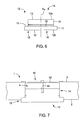
- FIG. 6 is a side plan view of the closure body, shown without a sealing member, according to one or more aspects of the present disclosure.
- FIG. 7 is an enlarged axial cross-sectional view of one closure device installed within a casing access opening, shown with an exemplary embodiment of a retainer, according to one or more aspects of the present disclosure.
- first and second features are formed in direct contact
- additional features may be formed interposing the first and second features, such that the first and second features may not be in direct contact.
- exemplary embodiments presented below may be combined in any combination of ways, i.e., any element from one exemplary embodiment may be used in any other exemplary embodiment, without departing from the scope of the disclosure.
- FIGS. 1-7 illustrate a closure device 10 for a casing assembly or casing 1 of a compressor C.
- the compressor C may include a high-pressure turbo compressor.
- the casing 1 may include a central longitudinal axis A C , an inner surface 2 defining an interior chamber C C , an opposing outer surface 3 , and at least one access opening 4 extending generally radially between the casing inner and outer surfaces 2 , 3 .
- the closure device 10 includes a generally cylindrical body 12 having a plug portion 14 and a head portion 16 .
- the plug portion 14 is disposeable at least partially within, and configured to substantially obstruct, the casing opening 4 .
- the head portion 16 may have a shoulder portion or shoulder 18 extending generally radially outwardly with respect to the plug portion 14 and disposeable generally against the casing inner surface 2 .
- the shoulder 18 may be biasable against the casing inner surface 2 by pressure within the casing 1 so as retain the plug portion 14 disposed within the access opening 4 .
- the closure device 10 enables the sealing of a compressor access opening 4 without the use of bolts, clamps or other fastening devices, thereby reducing costs and maintaining the structural integrity of the casing 1 .
- the casing 1 may include a plurality of access openings 4 and a plurality of the closure devices 10 , each closure device 10 being disposeable within each one of the plurality of access openings 4 .
- Each closure device 10 may be separately installable in each of the openings 4 ; in other words, each closure device 10 may be substantially identical to any other closure device 10 , and each access opening 4 may be substantially identical to any other opening 4 , such that each device 10 can be installed in any of the openings 4 .
- each closure device 10 and opening 4 may be formed (i.e., machined, fabricated, etc.) such that each closure device 10 is only installable in a single, designated one of the openings 4 .
- the casing 1 may have at least one enclosed inner circumferential surface 5 each defining a separate access opening 4 , each inner surface 5 being substantially circular and extending between the casing inner and outer surfaces 2 , 3 .
- each access opening 4 may be substantially circular and have an inside diameter ID A ( FIG. 4 ).
- each casing opening 4 has a centerline axis L C and a retention surface 6 extending circumferentially about the centerline L C .
- each access opening 4 may include a main bore section 4 a defined by the inner circumferential surface 5 and a counterbore section 4 b , as shown in FIG. 4 .
- the opening counterbore section 4 b may extend into the main bore section 4 a from the casing inner surface 2 , with the retention surface 6 extending generally radially between the main bore section 4 a and the counterbore section 4 b .
- the main bore section 4 a and the counterbore section 4 b may be sized to receive the plug portion 14 and at least a portion of the head portion 16 , respectively, of the closure device 10 , as described in further detail below.
- the plurality of access openings 4 may be spaced circumferentially about the casing axis A C , and in exemplary embodiments may be substantially equally angularly spaced and generally axially aligned, but may alternatively be unevenly angularly spaced and/or axially spaced or “staggered.” Furthermore, the access openings 4 may be located at least generally adjacent to an interface I C between two casing body sections 7 A, 7 B forming the casing 1 . In an exemplary embodiment, the access openings 4 may be located at an interface between a driver casing section 7 A and a casing section 7 B enclosing the components of a centrifugal compressor assembly (not shown). However, as can be appreciated by those skilled in the art, the access openings 4 and closure devices 10 may be disposed at any other appropriate location on the compressor C where access is desired (i.e., for maintenance, repair, etc.).
- the closure body 12 has a central axis A B and first and second ends 12 a , 12 b spaced apart along the axis A B .
- each end 12 a , 12 b may have a generally radial end surface 13 .
- the shoulder 18 may extend circumferentially about the axis A B , such that the plug portion 14 is offset radially inwardly from the head portion 16 .
- the plug portion 14 and the head portion 16 are each generally cylindrically-shaped, the cylindrical plug portion 14 being configured to be disposeable within each circular case opening 4 .
- each of the plug and head portions 14 , 16 may have a generally circular outer circumferential surface 15 , 17 , respectively, and an outside diameter OD P , OD H , with the head portion outside diameter OD H being greater than the plug portion outside diameter OD P .
- the shoulder 18 may be generally circular and have a contact surface 19 extending radially between the plug outer surface 15 and the head outer surface 18 , and thus from the plug outside diameter OD P to the head outside diameter OD H .
- the closure body 12 may be profiled to achieve minimum weights for handling.
- first and second ends 12 a , 12 b may both include a radius of curvature to decrease the overall mass of the closure body 12 .
- the plug portion 14 and the head portion 16 may each be cylindrically-shaped, the cylindrical plug portion 14 being configured to be disposeable within each circular case opening 4 .
- each plug portion 14 may be sized to be disposeable within and generally contactable with each casing opening inner surface 5 . In one embodiment, this may occur in the main bore section 4 a , such that the plug portion 14 may sealingly obstruct the casing access opening 4 . That is, the plug portion outside diameter OD P may be sized slightly less than the opening inside diameter ID A such that the plug portion 14 may fit within the access opening 4 with minimal clearance. Further, the head portion outside diameter OD H of each closure device 10 may be sized sufficiently larger than the inside diameter ID A of each access opening 4 such that the associated shoulder 18 overlaps the opening 4 or at least the main bore section 4 a thereof.
- the shoulder surface 19 may extend across and be disposed against sections 2 a of the casing inner surface 2 ( FIG. 2 ) or alternatively against the retention surface 6 ( FIGS. 3A and 3B ), such that pressure in the casing 1 may force the respective surfaces into substantially sealing contact.
- the inner end surface 13 on the closure body head portion 16 may be subjected to fluid pressure P in the casing chamber C C , which may generate a sealing force F directed generally radially outwardly with respect to the casing axis A C , and thus may bias or “force” the casing and closure surfaces into close and/or compressive contact, as indicated in FIGS. 3A and 3B .
- each closure body 12 may be formed such that the body shoulder surface 19 may be disposed against the retention surface 6 .
- the shoulder surface 19 and retention surface 6 may be angled or perhaps profiled to match the radius of curvature of the head portion 16 . Implementing such a profile may serve to provide a uniform bearing load when the casing 1 is fully pressurized.
- the plug portion 14 may occupy at least a portion of the main bore section 4 a , and the head portion 16 may be partially disposed within, and extend partly outward from, the counterbore section 4 b when a closure device 10 is installed within an access opening 4 .
- each access opening 4 and each closure device 10 may be relatively sized such that the main bore section 4 a may be axially longer or larger than the plug portion 14 based on structural design limits of the closure device 10 , such that the plug portion 14 only occupies a portion of the main bore section 4 a and the outer end surface 13 a may be spaced radially inwardly of the casing outer surface 3 .
- each head portion 16 may be axially larger than the counterbore section 4 b so as to extend partially into the casing chamber C C .
- each closure device body 12 may be configured such that the plug portion 14 occupies the entire main bore section 4 a , or even extends radially outwardly from the casing outer surface 3 .
- the head portion 16 may be disposed substantially entirely within the counterbore section 4 b , or/and the access openings 4 may be formed without counterbore sections 4 b , such that the entire head portion 16 of each closure device 10 may be disposed within the casing chamber C C .
- each closure device 10 may also include a generally annular sealing member 30 disposed about the plug portion 14 .
- the sealing member 30 may be configured to prevent fluid flow between the plug portion 14 and the access opening 4 , and thus may substantially seal any clearance space between the plug portion 14 and the access opening 4 . As such, the sealing member 30 may prevent fluids within the casing interior chamber C C from passing to the exterior environment, and vice-versa.
- the plug portion 14 of each closure device 10 may include an annular groove 32 extending inwardly from the outer circumferential surface 15 , wherein the sealing member 30 may be at least partially disposed within the groove 32 .
- the sealing member 30 may be a commercially-available elastomeric device, such as a conventional “O-ring,” but may also be formed in any appropriate, alternative manner depending on the particular application.
- each closure device 10 may include at least one retainer 40 configured to retain the closure device plug portion 14 disposed within one of the casing access openings 4 .
- An exemplary retainer 40 may function to prevent the closure device 10 from dislodging from the access opening 4 , and potentially falling into the casing interior chamber C C , when pressure external of the casing 1 exceeds the casing internal pressure.
- the retainer 40 may be formed in any appropriate manner, such as for example, being formed as one or more bolts extending through the casing 1 and engageable with the closure body 12 , one or more retainer rings/ring segments, etc.
- the retainer 40 may include a “hanger” bracket 42 engageable with the casing opening 4 and threaded rod 44 (e.g., a screw) extending between the bracket and the closure device body 12 , such that the rod 44 is either advanced into body 12 to pull it toward the bracket, and thus retained in the opening 4 , or withdrawn from the body 12 to permit the closure device 10 to be removed from the opening 4 .
- rod 44 e.g., a screw
- closure device 10 of the present disclosure is specifically described and depicted as being used in a high-pressure casing of a centrifugal compressor assembly, the closure device 10 may be used with any other high or low pressure casing assembly, such as for example, a low pressure centrifugal compressor, a reciprocating compressor or any other type of fluid machinery.
Abstract
Description
Claims (5)
Priority Applications (3)
| Application Number | Priority Date | Filing Date | Title |
|---|---|---|---|
| US12/409,741 US8061972B2 (en) | 2009-03-24 | 2009-03-24 | High pressure casing access cover |
| EP10756545.9A EP2411722B1 (en) | 2009-03-24 | 2010-02-26 | High pressure casing access cover |
| PCT/US2010/025650 WO2010110992A1 (en) | 2009-03-24 | 2010-02-26 | High pressure casing access cover |
Applications Claiming Priority (1)
| Application Number | Priority Date | Filing Date | Title |
|---|---|---|---|
| US12/409,741 US8061972B2 (en) | 2009-03-24 | 2009-03-24 | High pressure casing access cover |
Publications (2)
| Publication Number | Publication Date |
|---|---|
| US20100247299A1 US20100247299A1 (en) | 2010-09-30 |
| US8061972B2 true US8061972B2 (en) | 2011-11-22 |
Family
ID=42781365
Family Applications (1)
| Application Number | Title | Priority Date | Filing Date |
|---|---|---|---|
| US12/409,741 Expired - Fee Related US8061972B2 (en) | 2009-03-24 | 2009-03-24 | High pressure casing access cover |
Country Status (3)
| Country | Link |
|---|---|
| US (1) | US8061972B2 (en) |
| EP (1) | EP2411722B1 (en) |
| WO (1) | WO2010110992A1 (en) |
Cited By (2)
| Publication number | Priority date | Publication date | Assignee | Title |
|---|---|---|---|---|
| US20100119392A1 (en) * | 2007-06-06 | 2010-05-13 | Nippon Pillar Packaing Co., Ltd. | Reciprocating pump |
| US20140373610A1 (en) * | 2013-06-21 | 2014-12-25 | United Technologies Corporation | Engine inspection apparatus and system |
Families Citing this family (29)
| Publication number | Priority date | Publication date | Assignee | Title |
|---|---|---|---|---|
| US8075668B2 (en) | 2005-03-29 | 2011-12-13 | Dresser-Rand Company | Drainage system for compressor separators |
| US8434998B2 (en) | 2006-09-19 | 2013-05-07 | Dresser-Rand Company | Rotary separator drum seal |
| MX2009003119A (en) | 2006-09-21 | 2009-04-06 | Dresser Rand Co | Separator drum and compressor impeller assembly. |
| MX2009003177A (en) | 2006-09-25 | 2009-04-03 | Dresser Rand Co | Axially moveable spool connector. |
| WO2008039446A2 (en) | 2006-09-25 | 2008-04-03 | Dresser-Rand Company | Fluid deflector for fluid separator devices |
| CA2663883C (en) | 2006-09-25 | 2015-02-03 | Kevin M. Majot | Coupling guard system |
| WO2008039733A2 (en) | 2006-09-25 | 2008-04-03 | Dresser-Rand Company | Compressor mounting system |
| MX2009003175A (en) | 2006-09-25 | 2009-04-03 | Dresser Rand Co | Access cover for pressurized connector spool. |
| BRPI0717253B1 (en) | 2006-09-26 | 2018-05-08 | Dresser Rand Co | fluid separator |
| US8408879B2 (en) | 2008-03-05 | 2013-04-02 | Dresser-Rand Company | Compressor assembly including separator and ejector pump |
| US8079805B2 (en) | 2008-06-25 | 2011-12-20 | Dresser-Rand Company | Rotary separator and shaft coupler for compressors |
| US8062400B2 (en) | 2008-06-25 | 2011-11-22 | Dresser-Rand Company | Dual body drum for rotary separators |
| US7922218B2 (en) | 2008-06-25 | 2011-04-12 | Dresser-Rand Company | Shear ring casing coupler device |
| US8210804B2 (en) | 2009-03-20 | 2012-07-03 | Dresser-Rand Company | Slidable cover for casing access port |
| US8087901B2 (en) | 2009-03-20 | 2012-01-03 | Dresser-Rand Company | Fluid channeling device for back-to-back compressors |
| US8061972B2 (en) | 2009-03-24 | 2011-11-22 | Dresser-Rand Company | High pressure casing access cover |
| WO2011034764A2 (en) | 2009-09-15 | 2011-03-24 | Dresser-Rand Company | Improved density-based compact separator |
| EP2533905B1 (en) | 2010-02-10 | 2018-07-04 | Dresser-Rand Company | Separator fluid collector and method |
| US8673159B2 (en) | 2010-07-15 | 2014-03-18 | Dresser-Rand Company | Enhanced in-line rotary separator |
| US8663483B2 (en) | 2010-07-15 | 2014-03-04 | Dresser-Rand Company | Radial vane pack for rotary separators |
| WO2012012018A2 (en) | 2010-07-20 | 2012-01-26 | Dresser-Rand Company | Combination of expansion and cooling to enhance separation |
| WO2012012143A2 (en) | 2010-07-21 | 2012-01-26 | Dresser-Rand Company | Multiple modular in-line rotary separator bundle |
| US8596292B2 (en) | 2010-09-09 | 2013-12-03 | Dresser-Rand Company | Flush-enabled controlled flow drain |
| US8994237B2 (en) | 2010-12-30 | 2015-03-31 | Dresser-Rand Company | Method for on-line detection of liquid and potential for the occurrence of resistance to ground faults in active magnetic bearing systems |
| WO2013109235A2 (en) | 2010-12-30 | 2013-07-25 | Dresser-Rand Company | Method for on-line detection of resistance-to-ground faults in active magnetic bearing systems |
| US9551349B2 (en) | 2011-04-08 | 2017-01-24 | Dresser-Rand Company | Circulating dielectric oil cooling system for canned bearings and canned electronics |
| EP2715167B1 (en) | 2011-05-27 | 2017-08-30 | Dresser-Rand Company | Segmented coast-down bearing for magnetic bearing systems |
| US8851756B2 (en) | 2011-06-29 | 2014-10-07 | Dresser-Rand Company | Whirl inhibiting coast-down bearing for magnetic bearing systems |
| FR3052532B1 (en) * | 2016-06-10 | 2018-11-16 | Safran Aircraft Engines | SEALING DEVICE AND FLUID TEST SYSTEM COMPRISING THE SEALING DEVICE |
Citations (350)
| Publication number | Priority date | Publication date | Assignee | Title |
|---|---|---|---|---|
| US815812A (en) | 1904-08-01 | 1906-03-20 | George Westinghouse | Gas-purifying apparatus. |
| US1057613A (en) | 1910-11-01 | 1913-04-01 | William J Baldwin | Art of separating materials from gases. |
| US1061656A (en) | 1906-02-19 | 1913-05-13 | Joseph L Black | Separator for mechanical mixtures of gases. |
| US1480775A (en) | 1923-01-05 | 1924-01-15 | Nicholas C Marien | Air washer |
| US1622768A (en) | 1924-06-04 | 1927-03-29 | Cook Henry Denman | Pipe joint and connection |
| US1642454A (en) | 1926-05-19 | 1927-09-13 | Vaino W Malmstrom | Pump, compressor, or the like |
| US2006244A (en) | 1933-07-10 | 1935-06-25 | Julius F Kopsa | Liquid-separating device |
| US2300766A (en) | 1940-05-10 | 1942-11-03 | Bbc Brown Boveri & Cie | Multistage centrifugal compressor |
| US2328031A (en) | 1941-06-27 | 1943-08-31 | Dresser Mfg Company | Pipe clamp and method and apparatus for applying same |
| US2345437A (en) | 1943-07-09 | 1944-03-28 | Nat Tube Co | Thrust bearing |
| US2602462A (en) | 1950-12-12 | 1952-07-08 | Ralph A Barrett | Condensate unloader valve |
| US2811303A (en) | 1948-12-28 | 1957-10-29 | Joy Mfg Co | Impeller for axial flow fans |
| US2836117A (en) | 1954-07-06 | 1958-05-27 | Harry G Lankford | Clamp means |
| US2868565A (en) | 1956-05-01 | 1959-01-13 | George E Suderow | Releasable pivoted clamp for joining internally flanged structural members |
| US2897917A (en) | 1957-11-15 | 1959-08-04 | Fairchild Engine & Airplane | Apparatus for separating moisture and condensable vapors from a gas |
| US2932360A (en) | 1956-04-02 | 1960-04-12 | Carrier Corp | Apparatus for treating air |
| US2954841A (en) | 1956-11-16 | 1960-10-04 | Jersey Prod Res Co | Centrifugal separator |
| US2965286A (en) * | 1956-12-21 | 1960-12-20 | United Aircraft Corp | Compressor inspection port |
| US3044657A (en) | 1957-06-14 | 1962-07-17 | Richard H Horton | Flange and wall structure |
| US3191364A (en) | 1962-05-28 | 1965-06-29 | American Air Filter Co | Centrifugal dust separator |
| US3198214A (en) | 1962-10-30 | 1965-08-03 | R I V Anstalt Zur Verwaltung V | Fluid regulator |
| US3204696A (en) | 1963-09-16 | 1965-09-07 | California Research Corp | Apparatus for exhausting from downhole burner |
| US3213794A (en) | 1962-02-02 | 1965-10-26 | Nash Engineering Co | Centrifugal pump with gas separation means |
| US3220245A (en) | 1963-03-25 | 1965-11-30 | Baker Oil Tools Inc | Remotely operated underwater connection apparatus |
| US3273325A (en) | 1963-01-09 | 1966-09-20 | Universal Oil Prod Co | Rotary gas separator |
| US3352577A (en) | 1967-06-27 | 1967-11-14 | Koppers Co Inc | Coupling arrangement for filament reinforced thermosetting resin tubular members |
| US3362160A (en) * | 1966-09-16 | 1968-01-09 | Gen Electric | Gas turbine engine inspection apparatus |
| US3395511A (en) | 1963-10-03 | 1968-08-06 | Atlas Copco Ab | Method and means for obtaining dry gas or air |
| US3402434A (en) | 1965-12-22 | 1968-09-24 | Om Ltd | Drawing frame for high speed operation |
| US3431747A (en) | 1966-12-01 | 1969-03-11 | Hadi T Hashemi | Engine for exchanging energy between high and low pressure systems |
| US3454163A (en) | 1967-04-14 | 1969-07-08 | Ivan Jay Read | Method of separating solids from liquids |
| US3487432A (en) | 1967-03-09 | 1969-12-30 | Grundfos As | Coupling element for connection between a centrifugal pump and its drive motor |
| US3490209A (en) | 1968-02-20 | 1970-01-20 | United Aircraft Prod | Liquid separator |
| US3500614A (en) | 1969-02-10 | 1970-03-17 | Univ Illinois | Electro-aerodynamic precipitator |
| US3578342A (en) | 1969-01-14 | 1971-05-11 | Satterthwaite James G | Shaft seal |
| US3628812A (en) | 1969-12-01 | 1971-12-21 | Exxon Production Research Co | Removable pipe connector |
| US3672733A (en) | 1970-03-02 | 1972-06-27 | Skf Ind Trading & Dev | Axial bearing |
| US3814486A (en) | 1971-07-31 | 1974-06-04 | Skf Ind Trading & Dev | Hydrostatic thrust bearing supports |
| US3829179A (en) | 1972-03-03 | 1974-08-13 | Hitachi Ltd | Bearing device for vertical-shaft rotary machines |
| US3915673A (en) | 1969-04-10 | 1975-10-28 | Doryokuro Kakunenryo | Method and apparatus for separating gas mixture by centrifuging |
| US3975123A (en) | 1973-09-03 | 1976-08-17 | Svenska Rotor Maskiner Aktiebolag | Shaft seals for a screw compressor |
| US4033647A (en) | 1976-03-04 | 1977-07-05 | Borg-Warner Corporation | Tandem thrust bearing |
| US4059364A (en) | 1976-05-20 | 1977-11-22 | Kobe, Inc. | Pitot compressor with liquid separator |
| US4078809A (en) | 1977-01-17 | 1978-03-14 | Carrier Corporation | Shaft seal assembly for a rotary machine |
| US4087261A (en) | 1976-08-30 | 1978-05-02 | Biphase Engines, Inc. | Multi-phase separator |
| US4103899A (en) | 1975-10-01 | 1978-08-01 | United Technologies Corporation | Rotary seal with pressurized air directed at fluid approaching the seal |
| US4112687A (en) | 1975-09-16 | 1978-09-12 | William Paul Dixon | Power source for subsea oil wells |
| US4117359A (en) | 1974-01-30 | 1978-09-26 | Teldix Gmbh | Bearing and drive structure for spinning turbine |
| US4135542A (en) | 1977-09-12 | 1979-01-23 | Chisholm James R | Drain device for compressed air lines |
| US4141283A (en) | 1977-08-01 | 1979-02-27 | International Harvester Company | Pump unloading valve for use in agricultural tractor lift systems |
| US4146261A (en) | 1977-02-12 | 1979-03-27 | Motoren- Und Turbinen-Union Friedrichshafen Gmbh | Clamping arrangement |
| US4165622A (en) | 1976-04-30 | 1979-08-28 | Bourns, Inc. | Releasable locking and sealing assembly |
| US4174925A (en) | 1977-06-24 | 1979-11-20 | Cedomir M. Sliepcevich | Apparatus for exchanging energy between high and low pressure systems |
| US4182480A (en) | 1976-06-28 | 1980-01-08 | Ultra Centrifuge Nederland N.V. | Centrifuge for separating helium from natural gas |
| US4197990A (en) | 1978-08-28 | 1980-04-15 | General Electric Company | Electronic drain system |
| US4205927A (en) | 1977-12-16 | 1980-06-03 | Rolls-Royce Limited | Flanged joint structure for composite materials |
| US4227373A (en) | 1978-11-27 | 1980-10-14 | Biphase Energy Systems, Inc. | Waste heat recovery cycle for producing power and fresh water |
| US4259045A (en) | 1978-11-24 | 1981-03-31 | Kayabakogyokabushikikaisha | Gear pump or motor units with sleeve coupling for shafts |
| US4258551A (en) | 1979-03-05 | 1981-03-31 | Biphase Energy Systems | Multi-stage, wet steam turbine |
| US4278200A (en) | 1978-10-02 | 1981-07-14 | Westfalia Separator Ag | Continuously operating centrifugal separator drum for the concentration of suspended solids |
| US4298311A (en) | 1980-01-17 | 1981-11-03 | Biphase Energy Systems | Two-phase reaction turbine |
| US4333748A (en) | 1978-09-05 | 1982-06-08 | Baker International Corporation | Rotary gas/liquid separator |
| US4334592A (en) | 1980-12-04 | 1982-06-15 | Conoco Inc. | Sea water hydraulic fluid system for an underground vibrator |
| US4336693A (en) | 1980-05-01 | 1982-06-29 | Research-Cottrell Technologies Inc. | Refrigeration process using two-phase turbine |
| US4339923A (en) | 1980-04-01 | 1982-07-20 | Biphase Energy Systems | Scoop for removing fluid from rotating surface of two-phase reaction turbine |
| US4347900A (en) | 1980-06-13 | 1982-09-07 | Halliburton Company | Hydraulic connector apparatus and method |
| US4363608A (en) | 1981-04-20 | 1982-12-14 | Borg-Warner Corporation | Thrust bearing arrangement |
| US4374583A (en) | 1981-01-15 | 1983-02-22 | Halliburton Company | Sleeve valve |
| US4375975A (en) | 1980-06-04 | 1983-03-08 | Mgi International Inc. | Centrifugal separator |
| US4382804A (en) | 1978-02-26 | 1983-05-10 | Fred Mellor | Fluid/particle separator unit and method for separating particles from a flowing fluid |
| US4384724A (en) | 1978-08-17 | 1983-05-24 | Derman Karl G E | Sealing device |
| US4391102A (en) | 1981-08-10 | 1983-07-05 | Biphase Energy Systems | Fresh water production from power plant waste heat |
| US4396361A (en) | 1979-01-31 | 1983-08-02 | Carrier Corporation | Separation of lubricating oil from refrigerant gas in a reciprocating compressor |
| US4432470A (en) | 1981-01-21 | 1984-02-21 | Otto Engineering, Inc. | Multicomponent liquid mixing and dispensing assembly |
| US4438638A (en) | 1980-05-01 | 1984-03-27 | Biphase Energy Systems | Refrigeration process using two-phase turbine |
| US4441322A (en) | 1979-03-05 | 1984-04-10 | Transamerica Delaval Inc. | Multi-stage, wet steam turbine |
| US4442925A (en) | 1980-09-12 | 1984-04-17 | Nissan Motor Co., Ltd. | Vortex flow hydraulic shock absorber |
| US4453893A (en) | 1982-04-14 | 1984-06-12 | Hutmaker Marlin L | Drainage control for compressed air system |
| US4463567A (en) | 1982-02-16 | 1984-08-07 | Transamerica Delaval Inc. | Power production with two-phase expansion through vapor dome |
| US4471795A (en) | 1981-03-06 | 1984-09-18 | Linhardt Hans D | Contamination free method and apparatus for transfer of pressure energy between fluids |
| US4477223A (en) | 1982-06-11 | 1984-10-16 | Texas Turbine, Inc. | Sealing system for a turboexpander compressor |
| US4502839A (en) | 1982-11-02 | 1985-03-05 | Transamerica Delaval Inc. | Vibration damping of rotor carrying liquid ring |
| US4511309A (en) | 1983-01-10 | 1985-04-16 | Transamerica Delaval Inc. | Vibration damped asymmetric rotor carrying liquid ring or rings |
| US4531888A (en) | 1979-01-18 | 1985-07-30 | Benno Buchelt | Water turbine |
| US4536134A (en) | 1984-04-30 | 1985-08-20 | Hi-Tech Engineering, Inc. | Piston seal access apparatus |
| US4541531A (en) | 1983-08-04 | 1985-09-17 | Laros Equipment Company | Rotary separator |
| US4541607A (en) | 1983-10-06 | 1985-09-17 | Gebr. Eickhoff Maschinenfabrik Und Eisengiesserei M.B.H. | High-pressure ball valve |
| US4573527A (en) | 1983-07-29 | 1986-03-04 | Mcdonough M J | Heat exchanger closure connection |
| US4574815A (en) | 1984-08-29 | 1986-03-11 | Deere & Company | Rotor for an axial flow rotary separator |
| US4648806A (en) | 1985-06-12 | 1987-03-10 | Combustion Engineering, Inc. | Gas compressor |
| US4687017A (en) | 1986-04-28 | 1987-08-18 | Nupro Company | Inverted bellows valve |
| US4737081A (en) | 1986-07-07 | 1988-04-12 | Diesel Kiki Co., Ltd. | Variable capacity vane compressor |
| US4752185A (en) | 1987-08-03 | 1988-06-21 | General Electric Company | Non-contacting flowpath seal |
| US4807664A (en) | 1986-07-28 | 1989-02-28 | Ansan Industries Ltd. | Programmable flow control valve unit |
| US4813495A (en) | 1987-05-05 | 1989-03-21 | Conoco Inc. | Method and apparatus for deepwater drilling |
| US4821737A (en) | 1986-08-25 | 1989-04-18 | The Boc Group, Inc. | Water separator |
| US4826403A (en) | 1986-07-02 | 1989-05-02 | Rolls-Royce Plc | Turbine |
| US4830331A (en) | 1988-07-22 | 1989-05-16 | Vindum Jorgen O | High pressure fluid valve |
| US4832709A (en) | 1983-04-15 | 1989-05-23 | Allied Signal, Inc. | Rotary separator with a bladeless intermediate portion |
| US4904284A (en) | 1988-02-16 | 1990-02-27 | Mitsubishi Jukogyo Kabushiki Kaisha | Centrifugal type gas-liquid separator |
| US4955787A (en) * | 1989-06-12 | 1990-09-11 | Westinghouse Electric Corp. | Assembly for facilitating inservice inspection of a reactor coolant pump rotor |
| US4984830A (en) | 1988-11-02 | 1991-01-15 | Cooper Industries, Inc. | Collet type connector |
| US5007328A (en) | 1989-07-24 | 1991-04-16 | Otteman John H | Linear actuator |
| US5024585A (en) | 1990-04-09 | 1991-06-18 | Sta-Rite Industries, Inc. | Housing coupling mechanism |
| US5043617A (en) | 1989-06-20 | 1991-08-27 | Epic Products Limited | Multi-motor liquid sample and device |
| US5045046A (en) | 1990-11-13 | 1991-09-03 | Bond Lesley O | Apparatus for oil separation and recovery |
| US5044701A (en) | 1989-04-14 | 1991-09-03 | Miyako Jidosha Kogyo Kabushikikaisha | Elastic body apparatus especially intended for an anti-lock brake system |
| US5054995A (en) | 1989-11-06 | 1991-10-08 | Ingersoll-Rand Company | Apparatus for controlling a fluid compression system |
| US5064452A (en) | 1989-12-15 | 1991-11-12 | Mitsubishi Oil Co., Ltd. | Gas removable pump for liquid |
| US5080137A (en) | 1990-12-07 | 1992-01-14 | Adams Thomas R | Vortex flow regulators for storm sewer catch basins |
| US5190440A (en) | 1991-03-11 | 1993-03-02 | Dresser-Rand Company | Swirl control labyrinth seal |
| US5202024A (en) | 1989-06-13 | 1993-04-13 | Alfa-Laval Separation Ab | Centrifugal separator |
| US5202026A (en) | 1992-04-03 | 1993-04-13 | The United States Of America As Represented By The Secretary Of The Navy | Combined centrifugal force/gravity gas/liquid separator system |
| US5203891A (en) | 1992-04-03 | 1993-04-20 | The United States Of America As Represented By The Secretary Of The Navy | Gas/liquid separator |
| US5207810A (en) | 1991-04-24 | 1993-05-04 | Baker Hughes Incorporated | Submersible well pump gas separator |
| US5211427A (en) | 1990-12-22 | 1993-05-18 | Usui Kokusai Sangyo Kaisha Ltd. | Piping connector |
| US5246346A (en) | 1992-08-28 | 1993-09-21 | Tri-Line Corporation | Hydraulic power supply |
| US5285123A (en) | 1992-04-06 | 1994-02-08 | Doryokuro Kakunenryo Kaihatsu Jigyodan | Turbo-generator |
| US5306051A (en) | 1992-03-10 | 1994-04-26 | Hydrasearch Co., Inc. | Self-aligning and self-tightening hose coupling and method therefor |
| US5337779A (en) | 1990-05-23 | 1994-08-16 | Kabushiki Kaisha Fukuhara Seisakusho | Automatic drain device |
| US5378121A (en) | 1993-07-28 | 1995-01-03 | Hackett; William F. | Pump with fluid bearing |
| US5385446A (en) | 1992-05-05 | 1995-01-31 | Hays; Lance G. | Hybrid two-phase turbine |
| US5421708A (en) | 1994-02-16 | 1995-06-06 | Alliance Compressors Inc. | Oil separation and bearing lubrication in a high side co-rotating scroll compressor |
| US5431534A (en) * | 1993-07-21 | 1995-07-11 | (S.N.E.C.M.A.) Societe National D'etude Et De Construction De Moteurs D'aviation | Removable inspection hole plug |
| US5443581A (en) | 1992-12-03 | 1995-08-22 | Wood George & Co., Inc. | Clamp assembly for clamp hub connectors and a method of installing the same |
| US5484521A (en) | 1994-03-29 | 1996-01-16 | United Technologies Corporation | Rotary drum fluid/liquid separator with energy recovery means |
| US5496394A (en) | 1991-11-15 | 1996-03-05 | Nied; Roland | Cyclone separator |
| US5500039A (en) | 1993-07-23 | 1996-03-19 | Mitsubishi Jukogyo Kabushiki Kaisha | Gas-liquid separating apparatus |
| US5525146A (en) | 1994-11-01 | 1996-06-11 | Camco International Inc. | Rotary gas separator |
| US5531811A (en) | 1994-08-16 | 1996-07-02 | Marathon Oil Company | Method for recovering entrained liquid from natural gas |
| US5538259A (en) | 1994-03-19 | 1996-07-23 | Kaco Gmbh & Co. | Sealing device with centering ring for a water pump |
| US5542831A (en) | 1995-05-04 | 1996-08-06 | Carrier Corporation | Twin cylinder rotary compressor |
| US5545010A (en) * | 1993-05-13 | 1996-08-13 | Solar Turbines Incorporated | Method and apparatus for trim balancing a gas turbine engine |
| US5575309A (en) | 1993-04-03 | 1996-11-19 | Blp Components Limited | Solenoid actuator |
| US5585000A (en) | 1994-07-14 | 1996-12-17 | Metro International S.R.L. | Cyclone separator |
| US5605172A (en) | 1993-08-27 | 1997-02-25 | Baker Hughes Limited | Fluid control valve and method for subjecting a liquid to a controlled pressure drop |
| US5628623A (en) | 1993-02-12 | 1997-05-13 | Skaggs; Bill D. | Fluid jet ejector and ejection method |
| US5634492A (en) | 1994-05-11 | 1997-06-03 | Hoerbiger Ventilwerke Aktiengesellschaft | Compressor valve lifter |
| US5640472A (en) | 1995-06-07 | 1997-06-17 | United Technologies Corporation | Fiber optic sensor for magnetic bearings |
| US5641280A (en) | 1992-12-21 | 1997-06-24 | Svenska Rotor Maskiner Ab | Rotary screw compressor with shaft seal |
| US5653347A (en) | 1992-06-30 | 1997-08-05 | Cyclotech Ab | Cyclone separator |
| US5664420A (en) | 1992-05-05 | 1997-09-09 | Biphase Energy Company | Multistage two-phase turbine |
| US5683235A (en) | 1995-03-28 | 1997-11-04 | Dresser-Rand Company | Head port sealing gasket for a compressor |
| US5682759A (en) | 1996-02-27 | 1997-11-04 | Hays; Lance Gregory | Two phase nozzle equipped with flow divider |
| US5685691A (en) | 1996-07-01 | 1997-11-11 | Biphase Energy Company | Movable inlet gas barrier for a free surface liquid scoop |
| US5687249A (en) | 1993-09-06 | 1997-11-11 | Nippon Telephone And Telegraph | Method and apparatus for extracting features of moving objects |
| US5693125A (en) | 1995-12-22 | 1997-12-02 | United Technologies Corporation | Liquid-gas separator |
| US5703424A (en) | 1996-09-16 | 1997-12-30 | Mechanical Technology Inc. | Bias current control circuit |
| US5709528A (en) | 1996-12-19 | 1998-01-20 | Varian Associates, Inc. | Turbomolecular vacuum pumps with low susceptiblity to particulate buildup |
| US5713720A (en) | 1995-01-18 | 1998-02-03 | Sihi Industry Consult Gmbh | Turbo-machine with a balance piston |
| US5750040A (en) | 1996-05-30 | 1998-05-12 | Biphase Energy Company | Three-phase rotary separator |
| US5775882A (en) | 1995-01-30 | 1998-07-07 | Sanyo Electric Co., Ltd. | Multicylinder rotary compressor |
| US5779619A (en) | 1994-04-21 | 1998-07-14 | Alfa Laval Ab | Centrifugal separator |
| US5795135A (en) | 1995-12-05 | 1998-08-18 | Westinghouse Electric Corp. | Sub-sea pumping system and an associated method including pressure compensating arrangement for cooling and lubricating fluid |
| US5800092A (en) | 1992-06-30 | 1998-09-01 | Nill; Werner | Method for delaying run-off of flash-storm water or ordinary rainwater from roofs and other surfaces with water-retention capability |
| US5848616A (en) | 1994-05-02 | 1998-12-15 | Itt Automotive Europe Gmbh | Closing device for closing pressure fluid conveying channels in a housing |
| US5850857A (en) | 1996-07-22 | 1998-12-22 | Simpson; W. Dwain | Automatic pressure correcting vapor collection system |
| US5853585A (en) | 1994-12-14 | 1998-12-29 | Nth, Inc. | Rotary separator apparatus |
| US5863023A (en) | 1996-02-21 | 1999-01-26 | Aeroquip Corporation | Valved coupling for ultra high purtiy gas distribution system |
| US5867976A (en) * | 1997-08-01 | 1999-02-09 | General Electric Company | Self-retained borescope plug |
| US5899435A (en) | 1996-09-13 | 1999-05-04 | Westinghouse Air Brake Co. | Molded rubber valve seal for use in predetermined type valves, such as, a check valve in a regenerative desiccant air dryer |
| US5935053A (en) | 1995-03-10 | 1999-08-10 | Kvaerner Pulping As | Fractionator |
| US5938803A (en) | 1996-09-02 | 1999-08-17 | Shell Oil Company | Cyclone separator |
| US5938819A (en) | 1997-06-25 | 1999-08-17 | Gas Separation Technology Llc | Bulk separation of carbon dioxide from methane using natural clinoptilolite |
| US5951066A (en) | 1998-02-23 | 1999-09-14 | Erc Industries, Inc. | Connecting system for wellhead components |
| US5965022A (en) | 1996-07-06 | 1999-10-12 | Kvaerner Process Systems A.S. | Cyclone separator assembly |
| US5967746A (en) | 1997-07-30 | 1999-10-19 | Mitsubishi Heavy Industries, Ltd. | Gas turbine interstage portion seal device |
| US5971907A (en) | 1998-05-19 | 1999-10-26 | Bp Amoco Corporation | Continuous centrifugal separator with tapered internal feed distributor |
| US5971702A (en) | 1998-06-03 | 1999-10-26 | Dresser-Rand Company | Adjustable compressor bundle insertion and removal system |
| US5980218A (en) | 1996-09-17 | 1999-11-09 | Hitachi, Ltd. | Multi-stage compressor having first and second passages for cooling a motor during load and non-load operation |
| US5988524A (en) | 1997-04-07 | 1999-11-23 | Smc Kabushiki Kaisha | Suck back valve with sucking amount control mechanism |
| US6035934A (en) | 1998-02-24 | 2000-03-14 | Atlantic Richfield Company | Method and system for separating and injecting gas in a wellbore |
| US6059539A (en) | 1995-12-05 | 2000-05-09 | Westinghouse Government Services Company Llc | Sub-sea pumping system and associated method including pressure compensating arrangement for cooling and lubricating |
| US6068447A (en) | 1998-06-30 | 2000-05-30 | Standard Pneumatic Products, Inc. | Semi-automatic compressor controller and method of controlling a compressor |
| US6090299A (en) | 1996-05-30 | 2000-07-18 | Biphase Energy Company | Three-phase rotary separator |
| US6090174A (en) | 1997-04-01 | 2000-07-18 | U.S. Philips Corporation | Separator device provided with a cyclone chamber with a centrifugal unit, and vacuum cleaner provided with such a separator device |
| GB2323639B (en) | 1996-12-13 | 2000-08-23 | Knorr Bremse Systeme | Improvements relating to gas compressors |
| US6113675A (en) | 1998-10-16 | 2000-09-05 | Camco International, Inc. | Gas separator having a low rotating mass |
| US6123363A (en) | 1998-11-02 | 2000-09-26 | Uop Llc | Self-centering low profile connection with trapped gasket |
| US6145844A (en) | 1998-05-13 | 2000-11-14 | Dresser-Rand Company | Self-aligning sealing assembly for a rotating shaft |
| US6149825A (en) | 1999-07-12 | 2000-11-21 | Gargas; Joseph | Tubular vortex separator |
| US6151881A (en) | 1997-06-20 | 2000-11-28 | Mitsubishi Heavy Industries, Ltd. | Air separator for gas turbines |
| US6196962B1 (en) | 1996-09-17 | 2001-03-06 | Federal-Mogul Engineering Limited | Centrifugal separator with vortex disruption vanes |
| US6206202B1 (en) | 1996-03-04 | 2001-03-27 | Hosokawa Mikropul Gesellschaft Fur Mahl-Und Staubtechnik Mbh | Cyclone separator |
| US6214075B1 (en) | 1998-06-05 | 2001-04-10 | Khd Humboldt Wedag Ag | Cyclone separator |
| US6217637B1 (en) | 1999-03-10 | 2001-04-17 | Jerry L. Toney | Multiple stage high efficiency rotary filter system |
| US6227379B1 (en) | 1994-12-14 | 2001-05-08 | Nth, Inc. | Rotary separator apparatus and method |
| US20010007283A1 (en) | 2000-01-12 | 2001-07-12 | Johal Kashmir Singh | Method for boosting hydrocarbon production |
| US6277278B1 (en) | 1998-08-19 | 2001-08-21 | G.B.D. Corp. | Cyclone separator having a variable longitudinal profile |
| US6312021B1 (en) | 1996-01-26 | 2001-11-06 | Tru-Flex Metal Hose Corp. | End-slotted flexible metal hose |
| US20020009361A1 (en) | 1998-11-11 | 2002-01-24 | Arnd Reichert | Shaft bearing for a turbomachine, turbomachine, and method of operating a turbomachine |
| GB2337561B (en) | 1998-01-28 | 2002-01-30 | Inst Francais Du Petrole | Single-shaft compression-pumping device associated with a separator |
| US6372006B1 (en) | 1999-04-12 | 2002-04-16 | Bruno Pregenzer | Separator element for a centrifugal separator |
| US6375437B1 (en) | 2000-02-04 | 2002-04-23 | Stanley Fastening Systems, Lp | Power operated air compressor assembly |
| US6383262B1 (en) | 1998-02-24 | 2002-05-07 | Multiphase Power And Processing Technologies, Inc. | Energy recovery in a wellbore |
| US6394764B1 (en) | 2000-03-30 | 2002-05-28 | Dresser-Rand Company | Gas compression system and method utilizing gas seal control |
| US6398973B1 (en) | 1997-11-04 | 2002-06-04 | B.H.R. Group Limited | Cyclone separator |
| US6402465B1 (en) | 2001-03-15 | 2002-06-11 | Dresser-Rand Company | Ring valve for turbine flow control |
| US6426010B1 (en) | 1997-11-18 | 2002-07-30 | Total | Device and method for separating a heterogeneous mixture |
| JP2002242699A (en) | 2001-02-20 | 2002-08-28 | Kawasaki Heavy Ind Ltd | Gas turbine engine provided with foreign material removing structure |
| US6464469B1 (en) | 1999-07-16 | 2002-10-15 | Man Turbomaschinen Ag Ghh Borsig | Cooling system for electromagnetic bearings of a turbocompressor |
| US6468426B1 (en) | 1998-03-13 | 2002-10-22 | Georg Klass | Cyclone separator |
| US6467988B1 (en) | 2000-05-20 | 2002-10-22 | General Electric Company | Reducing cracking adjacent shell flange connecting bolts |
| US6485536B1 (en) | 2000-11-08 | 2002-11-26 | Proteam, Inc. | Vortex particle separator |
| US20030029318A1 (en) | 2001-08-03 | 2003-02-13 | Firey Joseph Carl | Flue gas cleaner |
| US20030035718A1 (en) | 2001-08-16 | 2003-02-20 | Langston Todd A. | Non-contacting clearance seal for high misalignment applications |
| US6530484B1 (en) | 1999-11-18 | 2003-03-11 | Multotec Process Equipment (Proprietary) Ltd. | Dense medium cyclone separator |
| US6531066B1 (en) | 1997-11-04 | 2003-03-11 | B.H.R. Group Limited | Cyclone separator |
| US6537035B2 (en) | 2001-04-10 | 2003-03-25 | Scott Shumway | Pressure exchange apparatus |
| US6540917B1 (en) | 2000-11-10 | 2003-04-01 | Purolator Facet Inc. | Cyclonic inertial fluid cleaning apparatus |
| US6547037B2 (en) | 2001-05-14 | 2003-04-15 | Dresser-Rand Company | Hydrate reducing and lubrication system and method for a fluid flow system |
| US6592654B2 (en) | 2001-06-25 | 2003-07-15 | Cryogenic Group Inc. | Liquid extraction and separation method for treating fluids utilizing flow swirl |
| US20030136094A1 (en) | 1999-05-21 | 2003-07-24 | Lewis Illingworth | Axial flow centrifugal dust separator |
| US6599086B2 (en) | 2001-07-03 | 2003-07-29 | Marc S. C. Soja | Adjustable pump wear plate positioning assembly |
| US6607348B2 (en) | 1998-12-10 | 2003-08-19 | Dresser-Rand S.A. | Gas compressor |
| US6617731B1 (en) | 2002-06-05 | 2003-09-09 | Buffalo Pumps, Inc. | Rotary pump with bearing wear indicator |
| US6616719B1 (en) | 2002-03-22 | 2003-09-09 | Yung Yung Sun | Air-liquid separating method and apparatus for compressed air |
| US6629825B2 (en) | 2001-11-05 | 2003-10-07 | Ingersoll-Rand Company | Integrated air compressor |
| US6631617B1 (en) | 2002-06-27 | 2003-10-14 | Tecumseh Products Company | Two stage hermetic carbon dioxide compressor |
| US6659143B1 (en) | 2002-05-31 | 2003-12-09 | Dresser, Inc. | Vapor recovery apparatus and method for gasoline dispensing systems |
| US6658986B2 (en) | 2002-04-11 | 2003-12-09 | Visteon Global Technologies, Inc. | Compressor housing with clamp |
| US20040007261A1 (en) | 2002-07-12 | 2004-01-15 | Cornwell James P. | Check valve |
| JP2004034017A (en) | 2002-07-05 | 2004-02-05 | Cnk:Kk | Centrifugal separator provided with liquid separation function |
| US6688802B2 (en) | 2001-09-10 | 2004-02-10 | Siemens Westinghouse Power Corporation | Shrunk on industrial coupling without keys for industrial system and associated methods |
| US6707200B2 (en) | 2000-11-14 | 2004-03-16 | Airex Corporation | Integrated magnetic bearing |
| US6719830B2 (en) | 1999-05-21 | 2004-04-13 | Vortex Holding Company | Toroidal vortex vacuum cleaner centrifugal dust separator |
| US6718955B1 (en) | 2003-04-25 | 2004-04-13 | Thomas Geoffrey Knight | Electric supercharger |
| US6764284B2 (en) | 2002-01-10 | 2004-07-20 | Parker-Hannifin Corporation | Pump mount using sanitary flange clamp |
| US6776812B2 (en) | 2001-07-06 | 2004-08-17 | Honda Giken Kogyo Kabushiki Kaisha | Gas liquid centrifugal separator |
| US20040170505A1 (en) | 2001-06-05 | 2004-09-02 | Lenderink Gerardus Maria | Compressor unit comprising a centrifugal compressor and an electric motor |
| US6802693B2 (en) | 1999-05-21 | 2004-10-12 | Vortex Holding Company | Vortex attractor with vanes attached to containing ring and backplate |
| US6802881B2 (en) | 1999-05-21 | 2004-10-12 | Vortex Hc, Llc | Rotating wave dust separator |
| US6811713B2 (en) | 2001-06-12 | 2004-11-02 | Hydrotreat, Inc. | Method and apparatus for mixing fluids, separating fluids, and separating solids from fluids |
| US6817846B2 (en) | 2002-06-13 | 2004-11-16 | Dresser-Rand Company | Gas compressor and method with improved valve assemblies |
| US6837913B2 (en) | 2002-04-04 | 2005-01-04 | KHD Humbold Wedag, AG | Cyclone separator |
| US6843836B2 (en) | 2000-04-11 | 2005-01-18 | Cash Engineering Research Pty Ltd. | Integrated compressor drier apparatus |
| US6878187B1 (en) | 2003-04-29 | 2005-04-12 | Energent Corporation | Seeded gas-liquid separator and process |
| US6893208B2 (en) | 2000-07-03 | 2005-05-17 | Nuovo Pigone Holdings S.P.A. | Drainage system for gas turbine supporting bearings |
| US6907933B2 (en) | 2003-02-13 | 2005-06-21 | Conocophillips Company | Sub-sea blow case compressor |
| US20050173337A1 (en) | 2003-04-18 | 2005-08-11 | Paul Costinel | Method and apparatus for separating immiscible phases with different densities |
| EP1582703A2 (en) | 2004-03-31 | 2005-10-05 | United Technologies Corporation | Deoiler for a lubrication system |
| US6979358B2 (en) | 2000-11-07 | 2005-12-27 | Shell Oil Company | Vertical cyclone separator |
| US7001448B1 (en) | 2001-06-13 | 2006-02-21 | National Tank Company | System employing a vortex finder tube for separating a liquid component from a gas stream |
| US7013978B2 (en) | 2001-10-12 | 2006-03-21 | Alpha Thames, Ltd. | System and method for separating fluids |
| US20060065609A1 (en) | 2004-09-30 | 2006-03-30 | Arthur David J | Fluid control device |
| US7022153B2 (en) | 2003-02-07 | 2006-04-04 | Mckenzie John R | Apparatus and method for the removal of moisture and mists from gas flows |
| US7022150B2 (en) | 2000-10-27 | 2006-04-04 | Alfa Laval Corporate Ab | Centrifugal separator having a rotor and driving means thereof |
| US7025890B2 (en) | 2003-04-24 | 2006-04-11 | Griswold Controls | Dual stage centrifugal liquid-solids separator |
| US7033411B2 (en) | 2000-10-27 | 2006-04-25 | Alfa Laval Corporate Ab | Centrifugal separator for cleaning of a gaseous fluid |
| US7033410B2 (en) | 2002-11-08 | 2006-04-25 | Mann & Hummel Gmbh | Centrifugal separator |
| US20060090430A1 (en) | 2003-01-11 | 2006-05-04 | Manngmbh | Centrifugal oil separator |
| US20060096933A1 (en) | 2004-11-08 | 2006-05-11 | Multiphase Power & Processing Technologies, Llc | Rotary separator and method |
| US7063465B1 (en) | 2003-03-21 | 2006-06-20 | Kingsbury, Inc. | Thrust bearing |
| US20060157406A1 (en) | 2004-09-09 | 2006-07-20 | Dresser-Rand Company | Rotary separator and method |
| US20060157251A1 (en) | 2003-07-02 | 2006-07-20 | Kvaerner Oilfield Products A.S. | Subsea compressor module and a method for controlling the pressure in such a subsea compressor module |
| US20060193728A1 (en) | 2005-02-26 | 2006-08-31 | Ingersoll-Rand Company | System and method for controlling a variable speed compressor during stopping |
| US7112036B2 (en) | 2003-10-28 | 2006-09-26 | Capstone Turbine Corporation | Rotor and bearing system for a turbomachine |
| US20060222515A1 (en) | 2005-03-29 | 2006-10-05 | Dresser-Rand Company | Drainage system for compressor separators |
| US20060230933A1 (en) | 2002-12-02 | 2006-10-19 | Rerum Cognitio Forschungszentrum Gmbh | Method for separating gas mixtures and a gas centrifuge for carrying out the method |
| US20060239831A1 (en) | 2004-09-21 | 2006-10-26 | George Washington University | Pressure exchange ejector |
| US7131292B2 (en) | 2004-02-18 | 2006-11-07 | Denso Corporation | Gas-liquid separator |
| US20060254659A1 (en) | 2003-01-07 | 2006-11-16 | Behr Lorraine S.A.R.L. | Protective cap for a sealing stopper on a container for a capacitor |
| US7144226B2 (en) | 2003-03-10 | 2006-12-05 | Thermodyn | Centrifugal compressor having a flexible coupling |
| US20060275160A1 (en) | 2005-05-17 | 2006-12-07 | Leu Shawn A | Pump improvements |
| US7159723B2 (en) | 2002-11-07 | 2007-01-09 | Mann & Hummel Gmbh | Cyclone separator |
| US7160518B2 (en) | 2002-04-11 | 2007-01-09 | Shell Oil Company | Cyclone separator |
| US7169305B2 (en) | 2001-11-27 | 2007-01-30 | Rodolfo Antonio M Gomez | Advanced liquid vortex separation system |
| US20070029091A1 (en) | 2003-09-12 | 2007-02-08 | Stinessen Kjell O | Subsea compression system and method |
| US20070036646A1 (en) | 2005-08-15 | 2007-02-15 | Honeywell International, Inc. | Integral diffuser and deswirler with continuous flow path deflected at assembly |
| US7185447B2 (en) | 2004-04-29 | 2007-03-06 | Peter Arbeiter | Drying device for drying a gas |
| US20070051245A1 (en) | 2005-02-03 | 2007-03-08 | Jangshik Yun | Wet type air purification apparatus utilizing a centrifugal impeller |
| US20070065317A1 (en) | 2005-09-19 | 2007-03-22 | Ingersoll-Rand Company | Air blower for a motor-driven compressor |
| US20070062374A1 (en) | 2005-09-20 | 2007-03-22 | Tempress Technologies, Inc. | Gas separator |
| US7204241B2 (en) | 2004-08-30 | 2007-04-17 | Honeywell International, Inc. | Compressor stage separation system |
| WO2007043889A1 (en) | 2005-10-07 | 2007-04-19 | Aker Kvaerner Subsea As | Apparatus and method for controlling supply of barrier gas in a compressor module |
| US20070084340A1 (en) | 2003-05-16 | 2007-04-19 | Jianwen Dou | Adjustable gas-liquid centrifugal separator and separating method |
| US20070140870A1 (en) | 2005-12-13 | 2007-06-21 | Tetsuhiko Fukanuma | Refrigerant compressor having an oil separator |
| US20070151922A1 (en) | 2006-01-05 | 2007-07-05 | Mian Farouk A | Spiral Speed Separator (SSS) |
| US7244111B2 (en) | 2003-07-05 | 2007-07-17 | Man Turbomuschinen Ag Schweiz | Compressor apparatus and method for the operation of the same |
| US20070163215A1 (en) | 2003-10-07 | 2007-07-19 | Lagerstadt Torgny | Centrifugal separator for cleaning gases |
| US20070172363A1 (en) | 2003-04-11 | 2007-07-26 | Pierre Laboube | Centrifugal motor-compressor unit |
| US7258713B2 (en) | 2004-08-27 | 2007-08-21 | Dreison International, Inc. | Inlet vane for centrifugal particle separator |
| US20070196215A1 (en) | 2006-02-17 | 2007-08-23 | Franco Frosini | Motor-compressor |
| WO2007103248A2 (en) | 2006-03-03 | 2007-09-13 | Dresser-Rand Company | Multiphase fluid processing device |
| US7270145B2 (en) | 2002-08-30 | 2007-09-18 | Haldex Brake Corporation | unloading/venting valve having integrated therewith a high-pressure protection valve |
| US20070227969A1 (en) | 2006-03-30 | 2007-10-04 | Total S.A. | Method and device for compressing a multiphase fluid |
| WO2007120506A2 (en) | 2006-03-31 | 2007-10-25 | Dresser-Rand Company | Control valve assembly for a compressor unloader |
| US20070294986A1 (en) | 2005-05-10 | 2007-12-27 | Klaus Beetz | Centrifugal Oil Mist Separation Device Integrated in an Axial Hollow Shaft of an Internal Combustion Engine |
| US7314560B2 (en) | 2003-10-10 | 2008-01-01 | Hideto Yoshida | Cyclone separator |
| US7323023B2 (en) | 2003-12-11 | 2008-01-29 | Hilti Aktiengesellschaft | Cyclone separator |
| US20080031732A1 (en) | 2005-11-30 | 2008-02-07 | Dresser-Rand Company | Closure device for a turbomachine casing |
| US7328749B2 (en) | 2003-06-06 | 2008-02-12 | Reitz Donald D | Method and apparatus for accumulating liquid and initiating upward movement when pumping a well with a sealed fluid displacement device |
| US20080039732A9 (en) | 1993-08-13 | 2008-02-14 | Bowman Harry F | Blood flow monitor with venous and arterial sensors |
| WO2008036221A2 (en) | 2006-09-19 | 2008-03-27 | Dresser-Rand Company | Rotary separator drum seal |
| WO2008039446A2 (en) | 2006-09-25 | 2008-04-03 | Dresser-Rand Company | Fluid deflector for fluid separator devices |
| WO2008039491A2 (en) | 2006-09-26 | 2008-04-03 | Dresser-Rand Company | Improved static fluid separator device |
| WO2008039733A2 (en) | 2006-09-25 | 2008-04-03 | Dresser-Rand Company | Compressor mounting system |
| WO2008039732A2 (en) | 2006-09-25 | 2008-04-03 | Dresser-Rand Company | Axially moveable spool connector |
| US7381235B2 (en) | 2001-12-13 | 2008-06-03 | Frederic Pierre Joseph Koene | Cyclone separator, liquid collecting box and pressure vessel |
| WO2008039731A3 (en) | 2006-09-25 | 2008-06-05 | Dresser Rand Co | Access cover for pressurized connector spool |
| WO2008036394A3 (en) | 2006-09-21 | 2008-07-03 | Dresser Rand Co | Separator drum and compressor impeller assembly |
| US7399412B2 (en) | 2003-12-30 | 2008-07-15 | Ejk Engineering Gmbh | Guide means for centrifugal force separators, especially cyclone separators |
| US20080246281A1 (en) | 2007-02-01 | 2008-10-09 | Agrawal Giridhari L | Turboalternator with hydrodynamic bearings |
| US7435290B2 (en) | 2004-06-26 | 2008-10-14 | Rolls-Royce Plc | Centrifugal gas/liquid separators |
| US20080315812A1 (en) | 2007-06-22 | 2008-12-25 | Oerlikon Textile Gmbh & Co. Kg | Method and device for starting an electric machine with a magnetically mounted rotor |
| US7470299B2 (en) | 2005-03-29 | 2008-12-30 | Samsung Gwangju Electronics Co., Ltd. | Multi-cyclone dust separator and a vacuum cleaner using the same |
| US7473083B2 (en) | 2006-03-14 | 2009-01-06 | Lg Electronics Inc. | Oil separating device for compressor |
| US20090013658A1 (en) | 2006-02-13 | 2009-01-15 | Alfa Laval Corporate Ab | Centrifugal separator |
| US20090015012A1 (en) | 2007-07-14 | 2009-01-15 | Andreas Metzler | Axial in-line turbomachine |
| US7479171B2 (en) | 2003-06-20 | 2009-01-20 | Lg Electronics Inc. | Dust separator for cyclone type cleaner |
| US20090025562A1 (en) | 2005-06-08 | 2009-01-29 | Alfa Laaval Corporate Ab | Centrifugal separator for cleaning of gas |
| US20090025563A1 (en) | 2006-02-13 | 2009-01-29 | Alfa Laval Corporate Ab | Centrifugal separator |
| US7494523B2 (en) | 2005-03-29 | 2009-02-24 | Samsung Gwangju Electronics Co., Ltd. | Multi-cyclone dust separator |
| US7501002B2 (en) | 2005-04-18 | 2009-03-10 | Samsung Gwangju Electronics Co., Ltd. | Cyclone dust separator and a vacuum cleaner having the same |
| US7520210B2 (en) | 2006-09-27 | 2009-04-21 | Visteon Global Technologies, Inc. | Oil separator for a fluid displacement apparatus |
| WO2008039734A3 (en) | 2006-09-25 | 2009-05-22 | Dresser Rand Co | Coupling guard system |
| US20090151928A1 (en) | 2007-12-17 | 2009-06-18 | Peter Francis Lawson | Electrical submersible pump and gas compressor |
| US20090159523A1 (en) | 2007-12-20 | 2009-06-25 | Mccutchen Wilmot H | Rotary annular crossflow filter, degasser, and sludge thickener |
| US20090169407A1 (en) | 2006-07-26 | 2009-07-02 | Xiaoying Yun | Rotor Compressor |
| US20090173095A1 (en) | 2008-01-07 | 2009-07-09 | Kanwal Bhatia | Fluid separator for a compressor |
| US7575422B2 (en) | 2002-10-15 | 2009-08-18 | Siemens Aktiengesellschaft | Compressor unit |
| US7578863B2 (en) | 2006-04-12 | 2009-08-25 | Mann & Hummel Gmbh | Multi-stage apparatus for separating liquid droplets from gases |
| WO2009111616A2 (en) | 2008-03-05 | 2009-09-11 | Dresser-Rand Company | Compressor assembly including separator and ejector pump |
| US7594941B2 (en) | 2006-08-23 | 2009-09-29 | University Of New Brunswick | Rotary gas cyclone separator |
| US7594942B2 (en) | 2003-09-09 | 2009-09-29 | Shell Oil Company | Gas/liquid separator |
| US20090266231A1 (en) | 2005-06-27 | 2009-10-29 | Peter Franzen | Method and Apparatus for Separation of Particles From a Flow of Gas |
| US7610955B2 (en) | 2001-10-11 | 2009-11-03 | ABI Technology, Inc | Controlled gas-lift heat exchange compressor |
| US7628836B2 (en) | 2006-05-08 | 2009-12-08 | Hamilton Sundstrand Corporation | Rotary drum separator system |
| US7637699B2 (en) | 2007-07-05 | 2009-12-29 | Babcock & Wilcox Power Generation Group, Inc. | Steam/water conical cyclone separator |
| WO2009158253A1 (en) | 2008-06-25 | 2009-12-30 | Dresser-Rand Company | Dual body drum for rotary separators |
| WO2009158252A1 (en) | 2008-06-25 | 2009-12-30 | Dresser-Rand Company | Rotary separator and shaft coupler for compressors |
| US20100043364A1 (en) | 2006-04-04 | 2010-02-25 | Winddrop | Liquid-gas separator, namely for vacuum cleaner |
| US20100043288A1 (en) | 2005-12-15 | 2010-02-25 | Paul Steven Wallace | Methods and systems for partial moderator bypass |
| US7674377B2 (en) | 2000-08-17 | 2010-03-09 | Carew E Bayne | Filter apparatus |
| US20100083690A1 (en) | 2007-08-17 | 2010-04-08 | Mitsubishi Heavy Industries, Ltd. | Multistage compressor |
| US7708808B1 (en) | 2007-06-01 | 2010-05-04 | Fisher-Klosterman, Inc. | Cyclone separator with rotating collection chamber |
| US20100143172A1 (en) | 2006-12-28 | 2010-06-10 | Mitsubishi Heavy Industries, Ltd. | Multistage Compressor |
| US7744663B2 (en) | 2006-02-16 | 2010-06-29 | General Electric Company | Methods and systems for advanced gasifier solids removal |
| US7748079B2 (en) | 2004-09-01 | 2010-07-06 | Bissell Homecare, Inc. | Cyclone separator with fine particle separation member |
| WO2010083427A1 (en) | 2009-01-15 | 2010-07-22 | Dresser-Rand Company | Shaft sealing with convergent nozzle |
| WO2010083416A1 (en) | 2009-01-16 | 2010-07-22 | Dresser-Rand Company | Compact shaft support device for turbomachines |
| US7766989B2 (en) | 2005-07-26 | 2010-08-03 | Parker Hannifin Limited | Separator assembly |
| US20100239437A1 (en) | 2009-03-20 | 2010-09-23 | Dresser-Rand Co. | Fluid channeling device for back-to-back compressors |
| US20100239419A1 (en) | 2009-03-20 | 2010-09-23 | Dresser-Rand Co. | Slidable cover for casing access port |
| US20100247299A1 (en) | 2009-03-24 | 2010-09-30 | Dresser-Rand Co. | High pressure casing access cover |
| US7811344B1 (en) | 2007-12-28 | 2010-10-12 | Bobby Ray Duke | Double-vortex fluid separator |
| US7811347B2 (en) | 2006-02-13 | 2010-10-12 | Alfa Laval Corporate Ab | Centrifugal separator |
| US7815415B2 (en) | 2004-09-29 | 2010-10-19 | Mitsubishi Heavy Industries, Ltd | Mounting structure for air separator, and gas turbine |
| US7846228B1 (en) | 2008-03-10 | 2010-12-07 | Research International, Inc. | Liquid particulate extraction device |
| US20110061536A1 (en) | 2009-09-15 | 2011-03-17 | Dresser-Rand Company | Density-based compact separator |
Family Cites Families (2)
| Publication number | Priority date | Publication date | Assignee | Title |
|---|---|---|---|---|
| FR2435655A3 (en) | 1978-09-07 | 1980-04-04 | Kernforschungsz Karlsruhe | FITTING PIECE TO INSERT INTO A WALL OPENING OF A VACUUM CONTAINER |
| JPH11210629A (en) * | 1998-01-21 | 1999-08-03 | Toyota Autom Loom Works Ltd | Plug sealing device of compressor |
-
2009
- 2009-03-24 US US12/409,741 patent/US8061972B2/en not_active Expired - Fee Related
-
2010
- 2010-02-26 EP EP10756545.9A patent/EP2411722B1/en not_active Not-in-force
- 2010-02-26 WO PCT/US2010/025650 patent/WO2010110992A1/en active Application Filing
Patent Citations (393)
| Publication number | Priority date | Publication date | Assignee | Title |
|---|---|---|---|---|
| US815812A (en) | 1904-08-01 | 1906-03-20 | George Westinghouse | Gas-purifying apparatus. |
| US1061656A (en) | 1906-02-19 | 1913-05-13 | Joseph L Black | Separator for mechanical mixtures of gases. |
| US1057613A (en) | 1910-11-01 | 1913-04-01 | William J Baldwin | Art of separating materials from gases. |
| US1480775A (en) | 1923-01-05 | 1924-01-15 | Nicholas C Marien | Air washer |
| US1622768A (en) | 1924-06-04 | 1927-03-29 | Cook Henry Denman | Pipe joint and connection |
| US1642454A (en) | 1926-05-19 | 1927-09-13 | Vaino W Malmstrom | Pump, compressor, or the like |
| US2006244A (en) | 1933-07-10 | 1935-06-25 | Julius F Kopsa | Liquid-separating device |
| US2300766A (en) | 1940-05-10 | 1942-11-03 | Bbc Brown Boveri & Cie | Multistage centrifugal compressor |
| US2328031A (en) | 1941-06-27 | 1943-08-31 | Dresser Mfg Company | Pipe clamp and method and apparatus for applying same |
| US2345437A (en) | 1943-07-09 | 1944-03-28 | Nat Tube Co | Thrust bearing |
| US2811303A (en) | 1948-12-28 | 1957-10-29 | Joy Mfg Co | Impeller for axial flow fans |
| US2602462A (en) | 1950-12-12 | 1952-07-08 | Ralph A Barrett | Condensate unloader valve |
| US2836117A (en) | 1954-07-06 | 1958-05-27 | Harry G Lankford | Clamp means |
| US2932360A (en) | 1956-04-02 | 1960-04-12 | Carrier Corp | Apparatus for treating air |
| US2868565A (en) | 1956-05-01 | 1959-01-13 | George E Suderow | Releasable pivoted clamp for joining internally flanged structural members |
| US2954841A (en) | 1956-11-16 | 1960-10-04 | Jersey Prod Res Co | Centrifugal separator |
| US2965286A (en) * | 1956-12-21 | 1960-12-20 | United Aircraft Corp | Compressor inspection port |
| US3044657A (en) | 1957-06-14 | 1962-07-17 | Richard H Horton | Flange and wall structure |
| US2897917A (en) | 1957-11-15 | 1959-08-04 | Fairchild Engine & Airplane | Apparatus for separating moisture and condensable vapors from a gas |
| US3213794A (en) | 1962-02-02 | 1965-10-26 | Nash Engineering Co | Centrifugal pump with gas separation means |
| US3191364A (en) | 1962-05-28 | 1965-06-29 | American Air Filter Co | Centrifugal dust separator |
| US3198214A (en) | 1962-10-30 | 1965-08-03 | R I V Anstalt Zur Verwaltung V | Fluid regulator |
| US3273325A (en) | 1963-01-09 | 1966-09-20 | Universal Oil Prod Co | Rotary gas separator |
| US3220245A (en) | 1963-03-25 | 1965-11-30 | Baker Oil Tools Inc | Remotely operated underwater connection apparatus |
| US3204696A (en) | 1963-09-16 | 1965-09-07 | California Research Corp | Apparatus for exhausting from downhole burner |
| US3395511A (en) | 1963-10-03 | 1968-08-06 | Atlas Copco Ab | Method and means for obtaining dry gas or air |
| US3402434A (en) | 1965-12-22 | 1968-09-24 | Om Ltd | Drawing frame for high speed operation |
| US3362160A (en) * | 1966-09-16 | 1968-01-09 | Gen Electric | Gas turbine engine inspection apparatus |
| US3431747A (en) | 1966-12-01 | 1969-03-11 | Hadi T Hashemi | Engine for exchanging energy between high and low pressure systems |
| US3487432A (en) | 1967-03-09 | 1969-12-30 | Grundfos As | Coupling element for connection between a centrifugal pump and its drive motor |
| US3454163A (en) | 1967-04-14 | 1969-07-08 | Ivan Jay Read | Method of separating solids from liquids |
| US3352577A (en) | 1967-06-27 | 1967-11-14 | Koppers Co Inc | Coupling arrangement for filament reinforced thermosetting resin tubular members |
| US3490209A (en) | 1968-02-20 | 1970-01-20 | United Aircraft Prod | Liquid separator |
| US3578342A (en) | 1969-01-14 | 1971-05-11 | Satterthwaite James G | Shaft seal |
| US3500614A (en) | 1969-02-10 | 1970-03-17 | Univ Illinois | Electro-aerodynamic precipitator |
| US3915673A (en) | 1969-04-10 | 1975-10-28 | Doryokuro Kakunenryo | Method and apparatus for separating gas mixture by centrifuging |
| US3628812A (en) | 1969-12-01 | 1971-12-21 | Exxon Production Research Co | Removable pipe connector |
| US3672733A (en) | 1970-03-02 | 1972-06-27 | Skf Ind Trading & Dev | Axial bearing |
| US3814486A (en) | 1971-07-31 | 1974-06-04 | Skf Ind Trading & Dev | Hydrostatic thrust bearing supports |
| US3829179A (en) | 1972-03-03 | 1974-08-13 | Hitachi Ltd | Bearing device for vertical-shaft rotary machines |
| US3975123A (en) | 1973-09-03 | 1976-08-17 | Svenska Rotor Maskiner Aktiebolag | Shaft seals for a screw compressor |
| US4117359A (en) | 1974-01-30 | 1978-09-26 | Teldix Gmbh | Bearing and drive structure for spinning turbine |
| US4112687A (en) | 1975-09-16 | 1978-09-12 | William Paul Dixon | Power source for subsea oil wells |
| US4103899A (en) | 1975-10-01 | 1978-08-01 | United Technologies Corporation | Rotary seal with pressurized air directed at fluid approaching the seal |
| US4033647A (en) | 1976-03-04 | 1977-07-05 | Borg-Warner Corporation | Tandem thrust bearing |
| US4165622A (en) | 1976-04-30 | 1979-08-28 | Bourns, Inc. | Releasable locking and sealing assembly |
| US4059364A (en) | 1976-05-20 | 1977-11-22 | Kobe, Inc. | Pitot compressor with liquid separator |
| US4182480A (en) | 1976-06-28 | 1980-01-08 | Ultra Centrifuge Nederland N.V. | Centrifuge for separating helium from natural gas |
| US4087261A (en) | 1976-08-30 | 1978-05-02 | Biphase Engines, Inc. | Multi-phase separator |
| US4078809A (en) | 1977-01-17 | 1978-03-14 | Carrier Corporation | Shaft seal assembly for a rotary machine |
| US4146261A (en) | 1977-02-12 | 1979-03-27 | Motoren- Und Turbinen-Union Friedrichshafen Gmbh | Clamping arrangement |
| US4174925A (en) | 1977-06-24 | 1979-11-20 | Cedomir M. Sliepcevich | Apparatus for exchanging energy between high and low pressure systems |
| US4141283A (en) | 1977-08-01 | 1979-02-27 | International Harvester Company | Pump unloading valve for use in agricultural tractor lift systems |
| US4135542A (en) | 1977-09-12 | 1979-01-23 | Chisholm James R | Drain device for compressed air lines |
| US4205927A (en) | 1977-12-16 | 1980-06-03 | Rolls-Royce Limited | Flanged joint structure for composite materials |
| US4382804A (en) | 1978-02-26 | 1983-05-10 | Fred Mellor | Fluid/particle separator unit and method for separating particles from a flowing fluid |
| US4384724A (en) | 1978-08-17 | 1983-05-24 | Derman Karl G E | Sealing device |
| US4197990A (en) | 1978-08-28 | 1980-04-15 | General Electric Company | Electronic drain system |
| US4333748A (en) | 1978-09-05 | 1982-06-08 | Baker International Corporation | Rotary gas/liquid separator |
| US4278200A (en) | 1978-10-02 | 1981-07-14 | Westfalia Separator Ag | Continuously operating centrifugal separator drum for the concentration of suspended solids |
| US4259045A (en) | 1978-11-24 | 1981-03-31 | Kayabakogyokabushikikaisha | Gear pump or motor units with sleeve coupling for shafts |
| US4227373A (en) | 1978-11-27 | 1980-10-14 | Biphase Energy Systems, Inc. | Waste heat recovery cycle for producing power and fresh water |
| US4531888A (en) | 1979-01-18 | 1985-07-30 | Benno Buchelt | Water turbine |
| US4396361A (en) | 1979-01-31 | 1983-08-02 | Carrier Corporation | Separation of lubricating oil from refrigerant gas in a reciprocating compressor |
| US4441322A (en) | 1979-03-05 | 1984-04-10 | Transamerica Delaval Inc. | Multi-stage, wet steam turbine |
| US4258551A (en) | 1979-03-05 | 1981-03-31 | Biphase Energy Systems | Multi-stage, wet steam turbine |
| US4298311A (en) | 1980-01-17 | 1981-11-03 | Biphase Energy Systems | Two-phase reaction turbine |
| US4339923A (en) | 1980-04-01 | 1982-07-20 | Biphase Energy Systems | Scoop for removing fluid from rotating surface of two-phase reaction turbine |
| US4336693A (en) | 1980-05-01 | 1982-06-29 | Research-Cottrell Technologies Inc. | Refrigeration process using two-phase turbine |
| US4438638A (en) | 1980-05-01 | 1984-03-27 | Biphase Energy Systems | Refrigeration process using two-phase turbine |
| US4375975A (en) | 1980-06-04 | 1983-03-08 | Mgi International Inc. | Centrifugal separator |
| US4468234A (en) | 1980-06-04 | 1984-08-28 | Mgi International, Inc. | Centrifugal separator |
| US4347900A (en) | 1980-06-13 | 1982-09-07 | Halliburton Company | Hydraulic connector apparatus and method |
| US4442925A (en) | 1980-09-12 | 1984-04-17 | Nissan Motor Co., Ltd. | Vortex flow hydraulic shock absorber |
| US4334592A (en) | 1980-12-04 | 1982-06-15 | Conoco Inc. | Sea water hydraulic fluid system for an underground vibrator |
| US4374583A (en) | 1981-01-15 | 1983-02-22 | Halliburton Company | Sleeve valve |
| US4432470A (en) | 1981-01-21 | 1984-02-21 | Otto Engineering, Inc. | Multicomponent liquid mixing and dispensing assembly |
| US4471795A (en) | 1981-03-06 | 1984-09-18 | Linhardt Hans D | Contamination free method and apparatus for transfer of pressure energy between fluids |
| US4363608A (en) | 1981-04-20 | 1982-12-14 | Borg-Warner Corporation | Thrust bearing arrangement |
| US4391102A (en) | 1981-08-10 | 1983-07-05 | Biphase Energy Systems | Fresh water production from power plant waste heat |
| US4463567A (en) | 1982-02-16 | 1984-08-07 | Transamerica Delaval Inc. | Power production with two-phase expansion through vapor dome |
| US4453893A (en) | 1982-04-14 | 1984-06-12 | Hutmaker Marlin L | Drainage control for compressed air system |
| US4477223A (en) | 1982-06-11 | 1984-10-16 | Texas Turbine, Inc. | Sealing system for a turboexpander compressor |
| US4502839A (en) | 1982-11-02 | 1985-03-05 | Transamerica Delaval Inc. | Vibration damping of rotor carrying liquid ring |
| US4511309A (en) | 1983-01-10 | 1985-04-16 | Transamerica Delaval Inc. | Vibration damped asymmetric rotor carrying liquid ring or rings |
| US4832709A (en) | 1983-04-15 | 1989-05-23 | Allied Signal, Inc. | Rotary separator with a bladeless intermediate portion |
| US4573527A (en) | 1983-07-29 | 1986-03-04 | Mcdonough M J | Heat exchanger closure connection |
| US4541531A (en) | 1983-08-04 | 1985-09-17 | Laros Equipment Company | Rotary separator |
| US4541607A (en) | 1983-10-06 | 1985-09-17 | Gebr. Eickhoff Maschinenfabrik Und Eisengiesserei M.B.H. | High-pressure ball valve |
| US4536134A (en) | 1984-04-30 | 1985-08-20 | Hi-Tech Engineering, Inc. | Piston seal access apparatus |
| US4574815A (en) | 1984-08-29 | 1986-03-11 | Deere & Company | Rotor for an axial flow rotary separator |
| US4648806A (en) | 1985-06-12 | 1987-03-10 | Combustion Engineering, Inc. | Gas compressor |
| US4687017A (en) | 1986-04-28 | 1987-08-18 | Nupro Company | Inverted bellows valve |
| US4826403A (en) | 1986-07-02 | 1989-05-02 | Rolls-Royce Plc | Turbine |
| US4737081A (en) | 1986-07-07 | 1988-04-12 | Diesel Kiki Co., Ltd. | Variable capacity vane compressor |
| US4807664A (en) | 1986-07-28 | 1989-02-28 | Ansan Industries Ltd. | Programmable flow control valve unit |
| US4821737A (en) | 1986-08-25 | 1989-04-18 | The Boc Group, Inc. | Water separator |
| US4813495A (en) | 1987-05-05 | 1989-03-21 | Conoco Inc. | Method and apparatus for deepwater drilling |
| US4752185A (en) | 1987-08-03 | 1988-06-21 | General Electric Company | Non-contacting flowpath seal |
| US4904284A (en) | 1988-02-16 | 1990-02-27 | Mitsubishi Jukogyo Kabushiki Kaisha | Centrifugal type gas-liquid separator |
| US4830331A (en) | 1988-07-22 | 1989-05-16 | Vindum Jorgen O | High pressure fluid valve |
| US4984830A (en) | 1988-11-02 | 1991-01-15 | Cooper Industries, Inc. | Collet type connector |
| US5044701A (en) | 1989-04-14 | 1991-09-03 | Miyako Jidosha Kogyo Kabushikikaisha | Elastic body apparatus especially intended for an anti-lock brake system |
| US4955787A (en) * | 1989-06-12 | 1990-09-11 | Westinghouse Electric Corp. | Assembly for facilitating inservice inspection of a reactor coolant pump rotor |
| US5202024A (en) | 1989-06-13 | 1993-04-13 | Alfa-Laval Separation Ab | Centrifugal separator |
| US5043617A (en) | 1989-06-20 | 1991-08-27 | Epic Products Limited | Multi-motor liquid sample and device |
| US5007328A (en) | 1989-07-24 | 1991-04-16 | Otteman John H | Linear actuator |
| US5054995A (en) | 1989-11-06 | 1991-10-08 | Ingersoll-Rand Company | Apparatus for controlling a fluid compression system |
| US5064452A (en) | 1989-12-15 | 1991-11-12 | Mitsubishi Oil Co., Ltd. | Gas removable pump for liquid |
| US5024585A (en) | 1990-04-09 | 1991-06-18 | Sta-Rite Industries, Inc. | Housing coupling mechanism |
| US5337779A (en) | 1990-05-23 | 1994-08-16 | Kabushiki Kaisha Fukuhara Seisakusho | Automatic drain device |
| US5045046A (en) | 1990-11-13 | 1991-09-03 | Bond Lesley O | Apparatus for oil separation and recovery |
| US5080137A (en) | 1990-12-07 | 1992-01-14 | Adams Thomas R | Vortex flow regulators for storm sewer catch basins |
| US5211427A (en) | 1990-12-22 | 1993-05-18 | Usui Kokusai Sangyo Kaisha Ltd. | Piping connector |
| US5190440A (en) | 1991-03-11 | 1993-03-02 | Dresser-Rand Company | Swirl control labyrinth seal |
| US5207810A (en) | 1991-04-24 | 1993-05-04 | Baker Hughes Incorporated | Submersible well pump gas separator |
| US5496394A (en) | 1991-11-15 | 1996-03-05 | Nied; Roland | Cyclone separator |
| US5306051A (en) | 1992-03-10 | 1994-04-26 | Hydrasearch Co., Inc. | Self-aligning and self-tightening hose coupling and method therefor |
| US5202026A (en) | 1992-04-03 | 1993-04-13 | The United States Of America As Represented By The Secretary Of The Navy | Combined centrifugal force/gravity gas/liquid separator system |
| US5203891A (en) | 1992-04-03 | 1993-04-20 | The United States Of America As Represented By The Secretary Of The Navy | Gas/liquid separator |
| US5285123A (en) | 1992-04-06 | 1994-02-08 | Doryokuro Kakunenryo Kaihatsu Jigyodan | Turbo-generator |
| US5720799A (en) | 1992-05-05 | 1998-02-24 | Biphase Energy Company | Multistage two-phase turbine |
| US5385446A (en) | 1992-05-05 | 1995-01-31 | Hays; Lance G. | Hybrid two-phase turbine |
| US6314738B1 (en) | 1992-05-05 | 2001-11-13 | Biphase Energy Company | Multistage two-phase turbine |
| US5946915A (en) | 1992-05-05 | 1999-09-07 | Biphase Energy Company | Multistage two-phase turbine |
| US6122915A (en) | 1992-05-05 | 2000-09-26 | Biphase Energy Company | Multistage two-phase turbine |
| US5525034A (en) | 1992-05-05 | 1996-06-11 | Biphase Energy Company | Hybrid two-phase turbine |
| US5664420A (en) | 1992-05-05 | 1997-09-09 | Biphase Energy Company | Multistage two-phase turbine |
| US5800092A (en) | 1992-06-30 | 1998-09-01 | Nill; Werner | Method for delaying run-off of flash-storm water or ordinary rainwater from roofs and other surfaces with water-retention capability |
| US5653347A (en) | 1992-06-30 | 1997-08-05 | Cyclotech Ab | Cyclone separator |
| US5246346A (en) | 1992-08-28 | 1993-09-21 | Tri-Line Corporation | Hydraulic power supply |
| US5443581A (en) | 1992-12-03 | 1995-08-22 | Wood George & Co., Inc. | Clamp assembly for clamp hub connectors and a method of installing the same |
| US5641280A (en) | 1992-12-21 | 1997-06-24 | Svenska Rotor Maskiner Ab | Rotary screw compressor with shaft seal |
| US5628623A (en) | 1993-02-12 | 1997-05-13 | Skaggs; Bill D. | Fluid jet ejector and ejection method |
| US5575309A (en) | 1993-04-03 | 1996-11-19 | Blp Components Limited | Solenoid actuator |
| US5545010A (en) * | 1993-05-13 | 1996-08-13 | Solar Turbines Incorporated | Method and apparatus for trim balancing a gas turbine engine |
| US5431534A (en) * | 1993-07-21 | 1995-07-11 | (S.N.E.C.M.A.) Societe National D'etude Et De Construction De Moteurs D'aviation | Removable inspection hole plug |
| US5500039A (en) | 1993-07-23 | 1996-03-19 | Mitsubishi Jukogyo Kabushiki Kaisha | Gas-liquid separating apparatus |
| US5378121A (en) | 1993-07-28 | 1995-01-03 | Hackett; William F. | Pump with fluid bearing |
| US20080039732A9 (en) | 1993-08-13 | 2008-02-14 | Bowman Harry F | Blood flow monitor with venous and arterial sensors |
| US5605172A (en) | 1993-08-27 | 1997-02-25 | Baker Hughes Limited | Fluid control valve and method for subjecting a liquid to a controlled pressure drop |
| US5687249A (en) | 1993-09-06 | 1997-11-11 | Nippon Telephone And Telegraph | Method and apparatus for extracting features of moving objects |
| US5421708A (en) | 1994-02-16 | 1995-06-06 | Alliance Compressors Inc. | Oil separation and bearing lubrication in a high side co-rotating scroll compressor |
| US5538259A (en) | 1994-03-19 | 1996-07-23 | Kaco Gmbh & Co. | Sealing device with centering ring for a water pump |
| US5484521A (en) | 1994-03-29 | 1996-01-16 | United Technologies Corporation | Rotary drum fluid/liquid separator with energy recovery means |
| US5779619A (en) | 1994-04-21 | 1998-07-14 | Alfa Laval Ab | Centrifugal separator |
| US5848616A (en) | 1994-05-02 | 1998-12-15 | Itt Automotive Europe Gmbh | Closing device for closing pressure fluid conveying channels in a housing |
| US5634492A (en) | 1994-05-11 | 1997-06-03 | Hoerbiger Ventilwerke Aktiengesellschaft | Compressor valve lifter |
| US5585000A (en) | 1994-07-14 | 1996-12-17 | Metro International S.R.L. | Cyclone separator |
| US5531811A (en) | 1994-08-16 | 1996-07-02 | Marathon Oil Company | Method for recovering entrained liquid from natural gas |
| US5525146A (en) | 1994-11-01 | 1996-06-11 | Camco International Inc. | Rotary gas separator |
| US6227379B1 (en) | 1994-12-14 | 2001-05-08 | Nth, Inc. | Rotary separator apparatus and method |
| US5853585A (en) | 1994-12-14 | 1998-12-29 | Nth, Inc. | Rotary separator apparatus |
| US5713720A (en) | 1995-01-18 | 1998-02-03 | Sihi Industry Consult Gmbh | Turbo-machine with a balance piston |
| US5775882A (en) | 1995-01-30 | 1998-07-07 | Sanyo Electric Co., Ltd. | Multicylinder rotary compressor |
| US5935053A (en) | 1995-03-10 | 1999-08-10 | Kvaerner Pulping As | Fractionator |
| US5683235A (en) | 1995-03-28 | 1997-11-04 | Dresser-Rand Company | Head port sealing gasket for a compressor |
| US5542831A (en) | 1995-05-04 | 1996-08-06 | Carrier Corporation | Twin cylinder rotary compressor |
| US5640472A (en) | 1995-06-07 | 1997-06-17 | United Technologies Corporation | Fiber optic sensor for magnetic bearings |
| US5795135A (en) | 1995-12-05 | 1998-08-18 | Westinghouse Electric Corp. | Sub-sea pumping system and an associated method including pressure compensating arrangement for cooling and lubricating fluid |
| US6059539A (en) | 1995-12-05 | 2000-05-09 | Westinghouse Government Services Company Llc | Sub-sea pumping system and associated method including pressure compensating arrangement for cooling and lubricating |
| US5693125A (en) | 1995-12-22 | 1997-12-02 | United Technologies Corporation | Liquid-gas separator |
| US6312021B1 (en) | 1996-01-26 | 2001-11-06 | Tru-Flex Metal Hose Corp. | End-slotted flexible metal hose |
| US5863023A (en) | 1996-02-21 | 1999-01-26 | Aeroquip Corporation | Valved coupling for ultra high purtiy gas distribution system |
| US5682759A (en) | 1996-02-27 | 1997-11-04 | Hays; Lance Gregory | Two phase nozzle equipped with flow divider |
| US6206202B1 (en) | 1996-03-04 | 2001-03-27 | Hosokawa Mikropul Gesellschaft Fur Mahl-Und Staubtechnik Mbh | Cyclone separator |
| US5750040A (en) | 1996-05-30 | 1998-05-12 | Biphase Energy Company | Three-phase rotary separator |
| US6090299A (en) | 1996-05-30 | 2000-07-18 | Biphase Energy Company | Three-phase rotary separator |
| US5685691A (en) | 1996-07-01 | 1997-11-11 | Biphase Energy Company | Movable inlet gas barrier for a free surface liquid scoop |
| US5965022A (en) | 1996-07-06 | 1999-10-12 | Kvaerner Process Systems A.S. | Cyclone separator assembly |
| US5850857A (en) | 1996-07-22 | 1998-12-22 | Simpson; W. Dwain | Automatic pressure correcting vapor collection system |
| US5938803A (en) | 1996-09-02 | 1999-08-17 | Shell Oil Company | Cyclone separator |
| US5899435A (en) | 1996-09-13 | 1999-05-04 | Westinghouse Air Brake Co. | Molded rubber valve seal for use in predetermined type valves, such as, a check valve in a regenerative desiccant air dryer |
| US5703424A (en) | 1996-09-16 | 1997-12-30 | Mechanical Technology Inc. | Bias current control circuit |
| US5980218A (en) | 1996-09-17 | 1999-11-09 | Hitachi, Ltd. | Multi-stage compressor having first and second passages for cooling a motor during load and non-load operation |
| US6196962B1 (en) | 1996-09-17 | 2001-03-06 | Federal-Mogul Engineering Limited | Centrifugal separator with vortex disruption vanes |
| GB2323639B (en) | 1996-12-13 | 2000-08-23 | Knorr Bremse Systeme | Improvements relating to gas compressors |
| US5709528A (en) | 1996-12-19 | 1998-01-20 | Varian Associates, Inc. | Turbomolecular vacuum pumps with low susceptiblity to particulate buildup |
| US6090174A (en) | 1997-04-01 | 2000-07-18 | U.S. Philips Corporation | Separator device provided with a cyclone chamber with a centrifugal unit, and vacuum cleaner provided with such a separator device |
| US5988524A (en) | 1997-04-07 | 1999-11-23 | Smc Kabushiki Kaisha | Suck back valve with sucking amount control mechanism |
| US6151881A (en) | 1997-06-20 | 2000-11-28 | Mitsubishi Heavy Industries, Ltd. | Air separator for gas turbines |
| US5938819A (en) | 1997-06-25 | 1999-08-17 | Gas Separation Technology Llc | Bulk separation of carbon dioxide from methane using natural clinoptilolite |
| US5967746A (en) | 1997-07-30 | 1999-10-19 | Mitsubishi Heavy Industries, Ltd. | Gas turbine interstage portion seal device |
| US5867976A (en) * | 1997-08-01 | 1999-02-09 | General Electric Company | Self-retained borescope plug |
| US6398973B1 (en) | 1997-11-04 | 2002-06-04 | B.H.R. Group Limited | Cyclone separator |
| US6531066B1 (en) | 1997-11-04 | 2003-03-11 | B.H.R. Group Limited | Cyclone separator |
| US6426010B1 (en) | 1997-11-18 | 2002-07-30 | Total | Device and method for separating a heterogeneous mixture |
| GB2337561B (en) | 1998-01-28 | 2002-01-30 | Inst Francais Du Petrole | Single-shaft compression-pumping device associated with a separator |
| US5951066A (en) | 1998-02-23 | 1999-09-14 | Erc Industries, Inc. | Connecting system for wellhead components |
| US6035934A (en) | 1998-02-24 | 2000-03-14 | Atlantic Richfield Company | Method and system for separating and injecting gas in a wellbore |
| US6383262B1 (en) | 1998-02-24 | 2002-05-07 | Multiphase Power And Processing Technologies, Inc. | Energy recovery in a wellbore |
| US6669845B2 (en) | 1998-03-13 | 2003-12-30 | Georg Klass | Cyclone separator |
| US6468426B1 (en) | 1998-03-13 | 2002-10-22 | Georg Klass | Cyclone separator |
| US6145844A (en) | 1998-05-13 | 2000-11-14 | Dresser-Rand Company | Self-aligning sealing assembly for a rotating shaft |
| US5971907A (en) | 1998-05-19 | 1999-10-26 | Bp Amoco Corporation | Continuous centrifugal separator with tapered internal feed distributor |
| US5971702A (en) | 1998-06-03 | 1999-10-26 | Dresser-Rand Company | Adjustable compressor bundle insertion and removal system |
| US6214075B1 (en) | 1998-06-05 | 2001-04-10 | Khd Humboldt Wedag Ag | Cyclone separator |
| US6068447A (en) | 1998-06-30 | 2000-05-30 | Standard Pneumatic Products, Inc. | Semi-automatic compressor controller and method of controlling a compressor |
| US6596046B2 (en) | 1998-08-19 | 2003-07-22 | G.B.D. Corp. | Cyclone separator having a variable longitudinal profile |
| US6277278B1 (en) | 1998-08-19 | 2001-08-21 | G.B.D. Corp. | Cyclone separator having a variable longitudinal profile |
| US6113675A (en) | 1998-10-16 | 2000-09-05 | Camco International, Inc. | Gas separator having a low rotating mass |
| US6123363A (en) | 1998-11-02 | 2000-09-26 | Uop Llc | Self-centering low profile connection with trapped gasket |
| US20020009361A1 (en) | 1998-11-11 | 2002-01-24 | Arnd Reichert | Shaft bearing for a turbomachine, turbomachine, and method of operating a turbomachine |
| US6607348B2 (en) | 1998-12-10 | 2003-08-19 | Dresser-Rand S.A. | Gas compressor |
| US6217637B1 (en) | 1999-03-10 | 2001-04-17 | Jerry L. Toney | Multiple stage high efficiency rotary filter system |
| US6372006B1 (en) | 1999-04-12 | 2002-04-16 | Bruno Pregenzer | Separator element for a centrifugal separator |
| US6802881B2 (en) | 1999-05-21 | 2004-10-12 | Vortex Hc, Llc | Rotating wave dust separator |
| US6719830B2 (en) | 1999-05-21 | 2004-04-13 | Vortex Holding Company | Toroidal vortex vacuum cleaner centrifugal dust separator |
| US20030136094A1 (en) | 1999-05-21 | 2003-07-24 | Lewis Illingworth | Axial flow centrifugal dust separator |
| US6802693B2 (en) | 1999-05-21 | 2004-10-12 | Vortex Holding Company | Vortex attractor with vanes attached to containing ring and backplate |
| US6149825A (en) | 1999-07-12 | 2000-11-21 | Gargas; Joseph | Tubular vortex separator |
| US6464469B1 (en) | 1999-07-16 | 2002-10-15 | Man Turbomaschinen Ag Ghh Borsig | Cooling system for electromagnetic bearings of a turbocompressor |
| US6530484B1 (en) | 1999-11-18 | 2003-03-11 | Multotec Process Equipment (Proprietary) Ltd. | Dense medium cyclone separator |
| US20010007283A1 (en) | 2000-01-12 | 2001-07-12 | Johal Kashmir Singh | Method for boosting hydrocarbon production |
| US6375437B1 (en) | 2000-02-04 | 2002-04-23 | Stanley Fastening Systems, Lp | Power operated air compressor assembly |
| US6394764B1 (en) | 2000-03-30 | 2002-05-28 | Dresser-Rand Company | Gas compression system and method utilizing gas seal control |
| US6843836B2 (en) | 2000-04-11 | 2005-01-18 | Cash Engineering Research Pty Ltd. | Integrated compressor drier apparatus |
| US6467988B1 (en) | 2000-05-20 | 2002-10-22 | General Electric Company | Reducing cracking adjacent shell flange connecting bolts |
| US6893208B2 (en) | 2000-07-03 | 2005-05-17 | Nuovo Pigone Holdings S.P.A. | Drainage system for gas turbine supporting bearings |
| US7674377B2 (en) | 2000-08-17 | 2010-03-09 | Carew E Bayne | Filter apparatus |
| US7022150B2 (en) | 2000-10-27 | 2006-04-04 | Alfa Laval Corporate Ab | Centrifugal separator having a rotor and driving means thereof |
| US7033411B2 (en) | 2000-10-27 | 2006-04-25 | Alfa Laval Corporate Ab | Centrifugal separator for cleaning of a gaseous fluid |
| US7056363B2 (en) | 2000-10-27 | 2006-06-06 | Alfa Laval Corporate Ab | Centrifugal separator for cleaning of a fluid |
| US6979358B2 (en) | 2000-11-07 | 2005-12-27 | Shell Oil Company | Vertical cyclone separator |
| US6485536B1 (en) | 2000-11-08 | 2002-11-26 | Proteam, Inc. | Vortex particle separator |
| US6540917B1 (en) | 2000-11-10 | 2003-04-01 | Purolator Facet Inc. | Cyclonic inertial fluid cleaning apparatus |
| US6707200B2 (en) | 2000-11-14 | 2004-03-16 | Airex Corporation | Integrated magnetic bearing |
| JP2002242699A (en) | 2001-02-20 | 2002-08-28 | Kawasaki Heavy Ind Ltd | Gas turbine engine provided with foreign material removing structure |
| JP3711028B2 (en) | 2001-02-20 | 2005-10-26 | 川崎重工業株式会社 | Gas turbine engine with foreign matter removal structure |
| US6402465B1 (en) | 2001-03-15 | 2002-06-11 | Dresser-Rand Company | Ring valve for turbine flow control |
| US6537035B2 (en) | 2001-04-10 | 2003-03-25 | Scott Shumway | Pressure exchange apparatus |
| US6547037B2 (en) | 2001-05-14 | 2003-04-15 | Dresser-Rand Company | Hydrate reducing and lubrication system and method for a fluid flow system |
| US20040170505A1 (en) | 2001-06-05 | 2004-09-02 | Lenderink Gerardus Maria | Compressor unit comprising a centrifugal compressor and an electric motor |
| US6811713B2 (en) | 2001-06-12 | 2004-11-02 | Hydrotreat, Inc. | Method and apparatus for mixing fluids, separating fluids, and separating solids from fluids |
| US7001448B1 (en) | 2001-06-13 | 2006-02-21 | National Tank Company | System employing a vortex finder tube for separating a liquid component from a gas stream |
| US6592654B2 (en) | 2001-06-25 | 2003-07-15 | Cryogenic Group Inc. | Liquid extraction and separation method for treating fluids utilizing flow swirl |
| US6599086B2 (en) | 2001-07-03 | 2003-07-29 | Marc S. C. Soja | Adjustable pump wear plate positioning assembly |
| US6776812B2 (en) | 2001-07-06 | 2004-08-17 | Honda Giken Kogyo Kabushiki Kaisha | Gas liquid centrifugal separator |
| US6530979B2 (en) | 2001-08-03 | 2003-03-11 | Joseph Carl Firey | Flue gas cleaner |
| US20030029318A1 (en) | 2001-08-03 | 2003-02-13 | Firey Joseph Carl | Flue gas cleaner |
| US20030035718A1 (en) | 2001-08-16 | 2003-02-20 | Langston Todd A. | Non-contacting clearance seal for high misalignment applications |
| US6688802B2 (en) | 2001-09-10 | 2004-02-10 | Siemens Westinghouse Power Corporation | Shrunk on industrial coupling without keys for industrial system and associated methods |
| US7610955B2 (en) | 2001-10-11 | 2009-11-03 | ABI Technology, Inc | Controlled gas-lift heat exchange compressor |
| US7013978B2 (en) | 2001-10-12 | 2006-03-21 | Alpha Thames, Ltd. | System and method for separating fluids |
| US6629825B2 (en) | 2001-11-05 | 2003-10-07 | Ingersoll-Rand Company | Integrated air compressor |
| US7169305B2 (en) | 2001-11-27 | 2007-01-30 | Rodolfo Antonio M Gomez | Advanced liquid vortex separation system |
| US7381235B2 (en) | 2001-12-13 | 2008-06-03 | Frederic Pierre Joseph Koene | Cyclone separator, liquid collecting box and pressure vessel |
| US6764284B2 (en) | 2002-01-10 | 2004-07-20 | Parker-Hannifin Corporation | Pump mount using sanitary flange clamp |
| US6616719B1 (en) | 2002-03-22 | 2003-09-09 | Yung Yung Sun | Air-liquid separating method and apparatus for compressed air |
| US6837913B2 (en) | 2002-04-04 | 2005-01-04 | KHD Humbold Wedag, AG | Cyclone separator |
| US7160518B2 (en) | 2002-04-11 | 2007-01-09 | Shell Oil Company | Cyclone separator |
| US6658986B2 (en) | 2002-04-11 | 2003-12-09 | Visteon Global Technologies, Inc. | Compressor housing with clamp |
| US6659143B1 (en) | 2002-05-31 | 2003-12-09 | Dresser, Inc. | Vapor recovery apparatus and method for gasoline dispensing systems |
| US6617731B1 (en) | 2002-06-05 | 2003-09-09 | Buffalo Pumps, Inc. | Rotary pump with bearing wear indicator |
| US6817846B2 (en) | 2002-06-13 | 2004-11-16 | Dresser-Rand Company | Gas compressor and method with improved valve assemblies |
| US6631617B1 (en) | 2002-06-27 | 2003-10-14 | Tecumseh Products Company | Two stage hermetic carbon dioxide compressor |
| JP2004034017A (en) | 2002-07-05 | 2004-02-05 | Cnk:Kk | Centrifugal separator provided with liquid separation function |
| US20040007261A1 (en) | 2002-07-12 | 2004-01-15 | Cornwell James P. | Check valve |
| US7270145B2 (en) | 2002-08-30 | 2007-09-18 | Haldex Brake Corporation | unloading/venting valve having integrated therewith a high-pressure protection valve |
| US7575422B2 (en) | 2002-10-15 | 2009-08-18 | Siemens Aktiengesellschaft | Compressor unit |
| US7159723B2 (en) | 2002-11-07 | 2007-01-09 | Mann & Hummel Gmbh | Cyclone separator |
| US7033410B2 (en) | 2002-11-08 | 2006-04-25 | Mann & Hummel Gmbh | Centrifugal separator |
| US20060230933A1 (en) | 2002-12-02 | 2006-10-19 | Rerum Cognitio Forschungszentrum Gmbh | Method for separating gas mixtures and a gas centrifuge for carrying out the method |
| US7591882B2 (en) | 2002-12-02 | 2009-09-22 | Rerum Cognito Forschungszentrum Gmbh | Method for separating gas mixtures and a gas centrifuge for carrying out the method |
| US20060254659A1 (en) | 2003-01-07 | 2006-11-16 | Behr Lorraine S.A.R.L. | Protective cap for a sealing stopper on a container for a capacitor |
| US7445653B2 (en) | 2003-01-11 | 2008-11-04 | Mann & Hummel Gmbh | Centrifugal oil separator |
| US20060090430A1 (en) | 2003-01-11 | 2006-05-04 | Manngmbh | Centrifugal oil separator |
| US7022153B2 (en) | 2003-02-07 | 2006-04-04 | Mckenzie John R | Apparatus and method for the removal of moisture and mists from gas flows |
| US6907933B2 (en) | 2003-02-13 | 2005-06-21 | Conocophillips Company | Sub-sea blow case compressor |
| US7144226B2 (en) | 2003-03-10 | 2006-12-05 | Thermodyn | Centrifugal compressor having a flexible coupling |
| US7063465B1 (en) | 2003-03-21 | 2006-06-20 | Kingsbury, Inc. | Thrust bearing |
| US20070172363A1 (en) | 2003-04-11 | 2007-07-26 | Pierre Laboube | Centrifugal motor-compressor unit |
| US20050173337A1 (en) | 2003-04-18 | 2005-08-11 | Paul Costinel | Method and apparatus for separating immiscible phases with different densities |
| US7025890B2 (en) | 2003-04-24 | 2006-04-11 | Griswold Controls | Dual stage centrifugal liquid-solids separator |
| US7335313B2 (en) | 2003-04-24 | 2008-02-26 | Griswold Controls | Dual stage centrifugal liquid-solids separator |
| US6718955B1 (en) | 2003-04-25 | 2004-04-13 | Thomas Geoffrey Knight | Electric supercharger |
| US6878187B1 (en) | 2003-04-29 | 2005-04-12 | Energent Corporation | Seeded gas-liquid separator and process |
| US20070084340A1 (en) | 2003-05-16 | 2007-04-19 | Jianwen Dou | Adjustable gas-liquid centrifugal separator and separating method |
| US7328749B2 (en) | 2003-06-06 | 2008-02-12 | Reitz Donald D | Method and apparatus for accumulating liquid and initiating upward movement when pumping a well with a sealed fluid displacement device |
| US7479171B2 (en) | 2003-06-20 | 2009-01-20 | Lg Electronics Inc. | Dust separator for cyclone type cleaner |
| US20060157251A1 (en) | 2003-07-02 | 2006-07-20 | Kvaerner Oilfield Products A.S. | Subsea compressor module and a method for controlling the pressure in such a subsea compressor module |
| US7244111B2 (en) | 2003-07-05 | 2007-07-17 | Man Turbomuschinen Ag Schweiz | Compressor apparatus and method for the operation of the same |
| US7594942B2 (en) | 2003-09-09 | 2009-09-29 | Shell Oil Company | Gas/liquid separator |
| US20070029091A1 (en) | 2003-09-12 | 2007-02-08 | Stinessen Kjell O | Subsea compression system and method |
| US20070163215A1 (en) | 2003-10-07 | 2007-07-19 | Lagerstadt Torgny | Centrifugal separator for cleaning gases |
| US7396373B2 (en) | 2003-10-07 | 2008-07-08 | 3Nine Ab | Centrifugal separator for cleaning gases |
| US7314560B2 (en) | 2003-10-10 | 2008-01-01 | Hideto Yoshida | Cyclone separator |
| US7112036B2 (en) | 2003-10-28 | 2006-09-26 | Capstone Turbine Corporation | Rotor and bearing system for a turbomachine |
| US7323023B2 (en) | 2003-12-11 | 2008-01-29 | Hilti Aktiengesellschaft | Cyclone separator |
| US7399412B2 (en) | 2003-12-30 | 2008-07-15 | Ejk Engineering Gmbh | Guide means for centrifugal force separators, especially cyclone separators |
| US7131292B2 (en) | 2004-02-18 | 2006-11-07 | Denso Corporation | Gas-liquid separator |
| US7377110B2 (en) | 2004-03-31 | 2008-05-27 | United Technologies Corporation | Deoiler for a lubrication system |
| EP1582703A2 (en) | 2004-03-31 | 2005-10-05 | United Technologies Corporation | Deoiler for a lubrication system |
| JP2005291202A (en) | 2004-03-31 | 2005-10-20 | United Technol Corp <Utc> | Oil separator and oil separating method |
| US7185447B2 (en) | 2004-04-29 | 2007-03-06 | Peter Arbeiter | Drying device for drying a gas |
| US7435290B2 (en) | 2004-06-26 | 2008-10-14 | Rolls-Royce Plc | Centrifugal gas/liquid separators |
| US7258713B2 (en) | 2004-08-27 | 2007-08-21 | Dreison International, Inc. | Inlet vane for centrifugal particle separator |
| US7204241B2 (en) | 2004-08-30 | 2007-04-17 | Honeywell International, Inc. | Compressor stage separation system |
| US7748079B2 (en) | 2004-09-01 | 2010-07-06 | Bissell Homecare, Inc. | Cyclone separator with fine particle separation member |
| US7241392B2 (en) | 2004-09-09 | 2007-07-10 | Dresser-Rand Company | Rotary separator and method |
| US20060157406A1 (en) | 2004-09-09 | 2006-07-20 | Dresser-Rand Company | Rotary separator and method |
| US20060239831A1 (en) | 2004-09-21 | 2006-10-26 | George Washington University | Pressure exchange ejector |
| US7815415B2 (en) | 2004-09-29 | 2010-10-19 | Mitsubishi Heavy Industries, Ltd | Mounting structure for air separator, and gas turbine |
| US20060065609A1 (en) | 2004-09-30 | 2006-03-30 | Arthur David J | Fluid control device |
| US7288202B2 (en) | 2004-11-08 | 2007-10-30 | Dresser-Rand Company | Rotary separator and method |
| US20060096933A1 (en) | 2004-11-08 | 2006-05-11 | Multiphase Power & Processing Technologies, Llc | Rotary separator and method |
| US20070051245A1 (en) | 2005-02-03 | 2007-03-08 | Jangshik Yun | Wet type air purification apparatus utilizing a centrifugal impeller |
| US20060193728A1 (en) | 2005-02-26 | 2006-08-31 | Ingersoll-Rand Company | System and method for controlling a variable speed compressor during stopping |
| US20060222515A1 (en) | 2005-03-29 | 2006-10-05 | Dresser-Rand Company | Drainage system for compressor separators |
| US7494523B2 (en) | 2005-03-29 | 2009-02-24 | Samsung Gwangju Electronics Co., Ltd. | Multi-cyclone dust separator |
| US7470299B2 (en) | 2005-03-29 | 2008-12-30 | Samsung Gwangju Electronics Co., Ltd. | Multi-cyclone dust separator and a vacuum cleaner using the same |
| US7501002B2 (en) | 2005-04-18 | 2009-03-10 | Samsung Gwangju Electronics Co., Ltd. | Cyclone dust separator and a vacuum cleaner having the same |
| US20070294986A1 (en) | 2005-05-10 | 2007-12-27 | Klaus Beetz | Centrifugal Oil Mist Separation Device Integrated in an Axial Hollow Shaft of an Internal Combustion Engine |
| US20060275160A1 (en) | 2005-05-17 | 2006-12-07 | Leu Shawn A | Pump improvements |
| US20090025562A1 (en) | 2005-06-08 | 2009-01-29 | Alfa Laaval Corporate Ab | Centrifugal separator for cleaning of gas |
| US20090266231A1 (en) | 2005-06-27 | 2009-10-29 | Peter Franzen | Method and Apparatus for Separation of Particles From a Flow of Gas |
| US7766989B2 (en) | 2005-07-26 | 2010-08-03 | Parker Hannifin Limited | Separator assembly |
| US20100257827A1 (en) | 2005-07-26 | 2010-10-14 | Brian Lane | Separator assembly |
| US20070036646A1 (en) | 2005-08-15 | 2007-02-15 | Honeywell International, Inc. | Integral diffuser and deswirler with continuous flow path deflected at assembly |
| US20070065317A1 (en) | 2005-09-19 | 2007-03-22 | Ingersoll-Rand Company | Air blower for a motor-driven compressor |
| US20100163232A1 (en) | 2005-09-20 | 2010-07-01 | Kolle Jack J | Gas separator |
| US20070062374A1 (en) | 2005-09-20 | 2007-03-22 | Tempress Technologies, Inc. | Gas separator |
| US7677308B2 (en) | 2005-09-20 | 2010-03-16 | Tempress Technologies Inc | Gas separator |
| WO2007043889A1 (en) | 2005-10-07 | 2007-04-19 | Aker Kvaerner Subsea As | Apparatus and method for controlling supply of barrier gas in a compressor module |
| US20080031732A1 (en) | 2005-11-30 | 2008-02-07 | Dresser-Rand Company | Closure device for a turbomachine casing |
| US20070140870A1 (en) | 2005-12-13 | 2007-06-21 | Tetsuhiko Fukanuma | Refrigerant compressor having an oil separator |
| US20100043288A1 (en) | 2005-12-15 | 2010-02-25 | Paul Steven Wallace | Methods and systems for partial moderator bypass |
| US20070151922A1 (en) | 2006-01-05 | 2007-07-05 | Mian Farouk A | Spiral Speed Separator (SSS) |
| US20090013658A1 (en) | 2006-02-13 | 2009-01-15 | Alfa Laval Corporate Ab | Centrifugal separator |
| US7811347B2 (en) | 2006-02-13 | 2010-10-12 | Alfa Laval Corporate Ab | Centrifugal separator |
| US7824459B2 (en) | 2006-02-13 | 2010-11-02 | Alfa Laval Corporate Ab | Centrifugal separator |
| US20090025563A1 (en) | 2006-02-13 | 2009-01-29 | Alfa Laval Corporate Ab | Centrifugal separator |
| US7824458B2 (en) | 2006-02-13 | 2010-11-02 | Alfa Laval Corporate Ab | Centrifugal separator |
| US7744663B2 (en) | 2006-02-16 | 2010-06-29 | General Electric Company | Methods and systems for advanced gasifier solids removal |
| US20070196215A1 (en) | 2006-02-17 | 2007-08-23 | Franco Frosini | Motor-compressor |
| WO2007103248A2 (en) | 2006-03-03 | 2007-09-13 | Dresser-Rand Company | Multiphase fluid processing device |
| US7473083B2 (en) | 2006-03-14 | 2009-01-06 | Lg Electronics Inc. | Oil separating device for compressor |
| US20070227969A1 (en) | 2006-03-30 | 2007-10-04 | Total S.A. | Method and device for compressing a multiphase fluid |
| MX2008012579A (en) | 2006-03-31 | 2008-12-12 | Dresser Rand Co | Control valve assembly for a compressor unloader. |
| CA2647511A1 (en) | 2006-03-31 | 2007-10-25 | Dresser-Rand Company | Control valve assembly for a compressor unloader |
| EP2013479A2 (en) | 2006-03-31 | 2009-01-14 | Dresser-Rand Company | Control valve assembly for a compressor unloader |
| WO2007120506A2 (en) | 2006-03-31 | 2007-10-25 | Dresser-Rand Company | Control valve assembly for a compressor unloader |
| US20100043364A1 (en) | 2006-04-04 | 2010-02-25 | Winddrop | Liquid-gas separator, namely for vacuum cleaner |
| US7578863B2 (en) | 2006-04-12 | 2009-08-25 | Mann & Hummel Gmbh | Multi-stage apparatus for separating liquid droplets from gases |
| US7628836B2 (en) | 2006-05-08 | 2009-12-08 | Hamilton Sundstrand Corporation | Rotary drum separator system |
| US20090169407A1 (en) | 2006-07-26 | 2009-07-02 | Xiaoying Yun | Rotor Compressor |
| US7594941B2 (en) | 2006-08-23 | 2009-09-29 | University Of New Brunswick | Rotary gas cyclone separator |
| WO2008036221A2 (en) | 2006-09-19 | 2008-03-27 | Dresser-Rand Company | Rotary separator drum seal |
| US20090304496A1 (en) | 2006-09-19 | 2009-12-10 | Dresser-Rand Company | Rotary separator drum seal |
| WO2008036394A3 (en) | 2006-09-21 | 2008-07-03 | Dresser Rand Co | Separator drum and compressor impeller assembly |
| US20100038309A1 (en) | 2006-09-21 | 2010-02-18 | Dresser-Rand Company | Separator drum and compressor impeller assembly |
| US20100044966A1 (en) | 2006-09-25 | 2010-02-25 | Dresser-Rand Company | Coupling guard system |
| US20100074768A1 (en) | 2006-09-25 | 2010-03-25 | Dresser-Rand Company | Access cover for pressurized connector spool |
| WO2008039733A2 (en) | 2006-09-25 | 2008-04-03 | Dresser-Rand Company | Compressor mounting system |
| WO2008039732A2 (en) | 2006-09-25 | 2008-04-03 | Dresser-Rand Company | Axially moveable spool connector |
| US20100007133A1 (en) | 2006-09-25 | 2010-01-14 | Dresser-Rand Company | Axially moveable spool connector |
| US20100021292A1 (en) | 2006-09-25 | 2010-01-28 | Dresser-Rand Company | Fluid deflector for fluid separator devices |
| WO2008039446A2 (en) | 2006-09-25 | 2008-04-03 | Dresser-Rand Company | Fluid deflector for fluid separator devices |
| WO2008039731A3 (en) | 2006-09-25 | 2008-06-05 | Dresser Rand Co | Access cover for pressurized connector spool |
| WO2008039734A3 (en) | 2006-09-25 | 2009-05-22 | Dresser Rand Co | Coupling guard system |
| US20100090087A1 (en) | 2006-09-25 | 2010-04-15 | Dresser-Rand Company | Compressor mounting system |
| WO2008039491A2 (en) | 2006-09-26 | 2008-04-03 | Dresser-Rand Company | Improved static fluid separator device |
| US20100072121A1 (en) | 2006-09-26 | 2010-03-25 | Dresser-Rand Company | Improved static fluid separator device |
| US7520210B2 (en) | 2006-09-27 | 2009-04-21 | Visteon Global Technologies, Inc. | Oil separator for a fluid displacement apparatus |
| US20100143172A1 (en) | 2006-12-28 | 2010-06-10 | Mitsubishi Heavy Industries, Ltd. | Multistage Compressor |
| US20080246281A1 (en) | 2007-02-01 | 2008-10-09 | Agrawal Giridhari L | Turboalternator with hydrodynamic bearings |
| US7708808B1 (en) | 2007-06-01 | 2010-05-04 | Fisher-Klosterman, Inc. | Cyclone separator with rotating collection chamber |
| US20080315812A1 (en) | 2007-06-22 | 2008-12-25 | Oerlikon Textile Gmbh & Co. Kg | Method and device for starting an electric machine with a magnetically mounted rotor |
| US7637699B2 (en) | 2007-07-05 | 2009-12-29 | Babcock & Wilcox Power Generation Group, Inc. | Steam/water conical cyclone separator |
| US20090015012A1 (en) | 2007-07-14 | 2009-01-15 | Andreas Metzler | Axial in-line turbomachine |
| US20100083690A1 (en) | 2007-08-17 | 2010-04-08 | Mitsubishi Heavy Industries, Ltd. | Multistage compressor |
| US20090151928A1 (en) | 2007-12-17 | 2009-06-18 | Peter Francis Lawson | Electrical submersible pump and gas compressor |
| US20090159523A1 (en) | 2007-12-20 | 2009-06-25 | Mccutchen Wilmot H | Rotary annular crossflow filter, degasser, and sludge thickener |
| US7811344B1 (en) | 2007-12-28 | 2010-10-12 | Bobby Ray Duke | Double-vortex fluid separator |
| US20090173095A1 (en) | 2008-01-07 | 2009-07-09 | Kanwal Bhatia | Fluid separator for a compressor |
| US7708537B2 (en) | 2008-01-07 | 2010-05-04 | Visteon Global Technologies, Inc. | Fluid separator for a compressor |
| WO2009111616A2 (en) | 2008-03-05 | 2009-09-11 | Dresser-Rand Company | Compressor assembly including separator and ejector pump |
| US20110017307A1 (en) | 2008-03-05 | 2011-01-27 | Dresser-Rand Company | Compressor assembly including separator and ejector pump |
| US7846228B1 (en) | 2008-03-10 | 2010-12-07 | Research International, Inc. | Liquid particulate extraction device |
| WO2009158253A1 (en) | 2008-06-25 | 2009-12-30 | Dresser-Rand Company | Dual body drum for rotary separators |
| WO2009158252A1 (en) | 2008-06-25 | 2009-12-30 | Dresser-Rand Company | Rotary separator and shaft coupler for compressors |
| US20090321343A1 (en) | 2008-06-25 | 2009-12-31 | Dresser-Rand Company | Dual body drum for rotary separators |
| US20090324391A1 (en) | 2008-06-25 | 2009-12-31 | Dresser-Rand Company | Rotary separator and shaft coupler for compressors |
| WO2010083427A1 (en) | 2009-01-15 | 2010-07-22 | Dresser-Rand Company | Shaft sealing with convergent nozzle |
| WO2010083416A1 (en) | 2009-01-16 | 2010-07-22 | Dresser-Rand Company | Compact shaft support device for turbomachines |
| US20100183438A1 (en) | 2009-01-16 | 2010-07-22 | Dresser-Rand Co. | Compact shaft support device for turbomachines |
| WO2010107579A1 (en) | 2009-03-20 | 2010-09-23 | Dresser-Rand Company | Slidable cover for casing access port |
| US20100239437A1 (en) | 2009-03-20 | 2010-09-23 | Dresser-Rand Co. | Fluid channeling device for back-to-back compressors |
| US20100239419A1 (en) | 2009-03-20 | 2010-09-23 | Dresser-Rand Co. | Slidable cover for casing access port |
| WO2010110992A1 (en) | 2009-03-24 | 2010-09-30 | Dresser-Rand Company | High pressure casing access cover |
| US20100247299A1 (en) | 2009-03-24 | 2010-09-30 | Dresser-Rand Co. | High pressure casing access cover |
| US20110061536A1 (en) | 2009-09-15 | 2011-03-17 | Dresser-Rand Company | Density-based compact separator |
| WO2011034764A2 (en) | 2009-09-15 | 2011-03-24 | Dresser-Rand Company | Improved density-based compact separator |
Non-Patent Citations (41)
| Title |
|---|
| Dresser-Rand, Inc. "High Pressure Air Compressor Model 13NL45," Oct. 28, 1991, 14 pages. |
| PCT/US2007/008149 International Preliminary Report on Patentability dated Sep. 30, 2008. |
| PCT/US2007/008149 International Search Report and Written Opinion dated Jul. 17, 2008. |
| PCT/US2007/020101 International Preliminary Report on Patentability dated Apr. 2, 2009. |
| PCT/US2007/020101 International Search Report dated Apr. 29, 2008. |
| PCT/US2007/020101 Written Opinion dated Mar. 19, 2009. |
| PCT/US2007/020471 International Preliminary Report on Patentability dated Apr. 2, 2009. |
| PCT/US2007/020471 International Search Report and Written Opinion dated Apr. 1, 2008. |
| PCT/US2007/020659 International Preliminary Report on Patentability dated Mar. 31, 2009. |
| PCT/US2007/020659 International Search Report and Written Opinion dated Sep. 17, 2008. |
| PCT/US2007/020768 International Preliminary Report on Patentability dated Mar. 31, 2009. |
| PCT/US2007/020768 International Search Report and Written Opinion dated Mar. 3, 2008. |
| PCT/US2007/079348 International Preliminary Report on Patentability dated Mar. 31, 2009. |
| PCT/US2007/079348 International Search Report dated Apr. 11, 2008. |
| PCT/US2007/079348 Written Opinion dated Jan. 25, 2008. |
| PCT/US2007/079349 International Preliminary Report on Patentability dated Mar. 31, 2009. |
| PCT/US2007/079349 International Search Report and Written Opinion dated Apr. 2, 2008. |
| PCT/US2007/079350 International Preliminary Report on Patentability dated Mar. 31, 2009. |
| PCT/US2007/079350 International Search Report dated Jul. 17, 2008. |
| PCT/US2007/079350 Written Opinion dated Mar. 25, 2009. |
| PCT/US2007/079352 International Preliminary Report on Patentability dated Mar. 31, 2009. |
| PCT/US2007/079352 International Search Report and Written Opinion dated Aug. 27, 2008. |
| PCT/US2009/036142 International Preliminary Report on Patentability dated Sep. 16, 2010. |
| PCT/US2009/036142 International Search Report dated Jan. 7, 2010. |
| PCT/US2009/036142 Written Opinion dated May 11, 2009. |
| PCT/US2009/047662 International Preliminary Report on Patentability dated Jan. 13, 2011. |
| PCT/US2009/047662 Written Opinion dated Aug. 20, 2009. |
| PCT/US2009/047667 International Report on Patentability dated Jan. 13, 2011. |
| PCT/US2009/047667 International Search Report dated Dec. 30, 2009. |
| PCT/US2009/047667 Written Opinion dated Aug. 7, 2009. |
| PCT/US2010/021199 International Preliminary Report on Patentability dated Mar. 29, 2011. |
| PCT/US2010/021199 International Search Report and Written Opinion dated Mar. 22, 2010. |
| PCT/US2010/021218 International Report on Patentability dated Feb. 2, 2011. |
| PCT/US2010/021218 International Search Report and Written Opinion dated Mar. 23, 2010. |
| PCT/US2010/025650 International Report on Patentability dated Mar. 14, 2011. |
| PCT/US2010/025650 International Search Report and Written Opinion dated Apr. 22, 2010. |
| PCT/US2010/025650 Notification of Transmittal of the International Preliminary Report on Patentability Mar. 14, 2011. |
| PCT/US2010/025650 Notification of Transmittal of the International Search Report and the Written Opinion of the International Searching Authority, or the Declaration dated Apr. 22, 2010. |
| PCT/US2010/025952 International Report on Patentability dated Mar. 14, 2011. |
| PCT/US2010/025952 International Search Report and Written Opinion dated Apr. 12, 2010. |
| Technical Manual-High Pressure Air Compressor Model 13NL45; Navsea S6220-AT-MMA-010/93236, pp. 3-23 to 3-32, Electric Boat Corporation, Groton, CT 06340, Oct. 28, 1991. |
Cited By (4)
| Publication number | Priority date | Publication date | Assignee | Title |
|---|---|---|---|---|
| US20100119392A1 (en) * | 2007-06-06 | 2010-05-13 | Nippon Pillar Packaing Co., Ltd. | Reciprocating pump |
| US8568114B2 (en) * | 2007-06-06 | 2013-10-29 | Nippon Pillar Packing Co., Ltd. | Reciprocating pump |
| US20140373610A1 (en) * | 2013-06-21 | 2014-12-25 | United Technologies Corporation | Engine inspection apparatus and system |
| US9880070B2 (en) * | 2013-06-21 | 2018-01-30 | United Technologies Corporation | Engine inspection apparatus and system |
Also Published As
| Publication number | Publication date |
|---|---|
| EP2411722A1 (en) | 2012-02-01 |
| EP2411722B1 (en) | 2015-10-14 |
| EP2411722A4 (en) | 2013-03-13 |
| WO2010110992A1 (en) | 2010-09-30 |
| US20100247299A1 (en) | 2010-09-30 |
Similar Documents
| Publication | Publication Date | Title |
|---|---|---|
| US8061972B2 (en) | High pressure casing access cover | |
| US8210804B2 (en) | Slidable cover for casing access port | |
| EP1960632B1 (en) | End closure device for a turbomachine casing | |
| US10605105B2 (en) | Bi-directional shaft seal | |
| CN104454757B (en) | hydraulic cylinder and its cylinder cover structure | |
| US9909440B2 (en) | Interlocking hole pattern seal | |
| CN110425281B (en) | Sealing arrangement for a gear unit output shaft and gear unit having a sealing arrangement | |
| US20140178182A1 (en) | Arrangement having a seal, seal, and turbocompressor | |
| US9915349B2 (en) | Dynamically non contacting seal | |
| US20170307019A1 (en) | Seal Assembly For A Turbomachine | |
| KR20080038039A (en) | Improved fluidic actuator for application inside turbomachinery | |
| CA2941783C (en) | Unitized lip seal for wash pipe stuffing box sealing system | |
| US10208802B2 (en) | Sealing device | |
| US8631961B2 (en) | End wall closure apparatus | |
| US3552789A (en) | Pressure vessel head retainer | |
| EP3597946B1 (en) | Axially spaced restricted damper | |
| US11326712B2 (en) | No-bolt valve assembly system | |
| US10837483B2 (en) | Self-locking threaded article with polygonal head and ratchet ring assembly | |
| KR20220148730A (en) | Sealing member and door actuator |
Legal Events
| Date | Code | Title | Description |
|---|---|---|---|
| AS | Assignment |
Owner name: DRESSER-RAND COMPANY, NEW YORK Free format text: ASSIGNMENT OF ASSIGNORS INTEREST;ASSIGNOR:MAIER, WILLIAM C.;REEL/FRAME:022547/0559 Effective date: 20090326 |
|
| STCF | Information on status: patent grant |
Free format text: PATENTED CASE |
|
| FPAY | Fee payment |
Year of fee payment: 4 |
|
| MAFP | Maintenance fee payment |
Free format text: PAYMENT OF MAINTENANCE FEE, 8TH YEAR, LARGE ENTITY (ORIGINAL EVENT CODE: M1552); ENTITY STATUS OF PATENT OWNER: LARGE ENTITY Year of fee payment: 8 |
|
| FEPP | Fee payment procedure |
Free format text: MAINTENANCE FEE REMINDER MAILED (ORIGINAL EVENT CODE: REM.); ENTITY STATUS OF PATENT OWNER: LARGE ENTITY |
|
| LAPS | Lapse for failure to pay maintenance fees |
Free format text: PATENT EXPIRED FOR FAILURE TO PAY MAINTENANCE FEES (ORIGINAL EVENT CODE: EXP.); ENTITY STATUS OF PATENT OWNER: LARGE ENTITY |
|
| STCH | Information on status: patent discontinuation |
Free format text: PATENT EXPIRED DUE TO NONPAYMENT OF MAINTENANCE FEES UNDER 37 CFR 1.362 |
|
| FP | Lapsed due to failure to pay maintenance fee |
Effective date: 20231122 |