US8041536B2 - Inclination calculation apparatus and inclination calculation program, and game apparatus and game program - Google Patents
Inclination calculation apparatus and inclination calculation program, and game apparatus and game program Download PDFInfo
- Publication number
- US8041536B2 US8041536B2 US12/835,355 US83535510A US8041536B2 US 8041536 B2 US8041536 B2 US 8041536B2 US 83535510 A US83535510 A US 83535510A US 8041536 B2 US8041536 B2 US 8041536B2
- Authority
- US
- United States
- Prior art keywords
- vector
- inclination
- acceleration
- controller
- calculated
- Prior art date
- Legal status (The legal status is an assumption and is not a legal conclusion. Google has not performed a legal analysis and makes no representation as to the accuracy of the status listed.)
- Active
Links
- 238000004364 calculation method Methods 0.000 title abstract description 121
- 230000001133 acceleration Effects 0.000 claims abstract description 272
- 238000003384 imaging method Methods 0.000 claims abstract description 94
- 238000000034 method Methods 0.000 claims description 54
- 238000012545 processing Methods 0.000 description 162
- 230000015654 memory Effects 0.000 description 60
- 239000003550 marker Substances 0.000 description 56
- 230000008859 change Effects 0.000 description 30
- 230000005484 gravity Effects 0.000 description 28
- 238000012937 correction Methods 0.000 description 19
- 238000001514 detection method Methods 0.000 description 18
- 230000014509 gene expression Effects 0.000 description 17
- 230000010365 information processing Effects 0.000 description 10
- 239000000758 substrate Substances 0.000 description 9
- 230000008901 benefit Effects 0.000 description 8
- 230000003287 optical effect Effects 0.000 description 8
- 238000004891 communication Methods 0.000 description 7
- 238000005516 engineering process Methods 0.000 description 7
- 238000006243 chemical reaction Methods 0.000 description 6
- 230000015572 biosynthetic process Effects 0.000 description 4
- 238000010586 diagram Methods 0.000 description 4
- 230000033001 locomotion Effects 0.000 description 4
- 230000003068 static effect Effects 0.000 description 4
- 238000003786 synthesis reaction Methods 0.000 description 4
- 230000005540 biological transmission Effects 0.000 description 3
- 230000006870 function Effects 0.000 description 2
- 238000009434 installation Methods 0.000 description 2
- 238000003825 pressing Methods 0.000 description 2
- 230000008569 process Effects 0.000 description 2
- 239000010453 quartz Substances 0.000 description 2
- VYPSYNLAJGMNEJ-UHFFFAOYSA-N silicon dioxide Inorganic materials O=[Si]=O VYPSYNLAJGMNEJ-UHFFFAOYSA-N 0.000 description 2
- XUIMIQQOPSSXEZ-UHFFFAOYSA-N Silicon Chemical compound [Si] XUIMIQQOPSSXEZ-UHFFFAOYSA-N 0.000 description 1
- 238000010168 coupling process Methods 0.000 description 1
- 238000005859 coupling reaction Methods 0.000 description 1
- 230000003111 delayed effect Effects 0.000 description 1
- 230000001687 destabilization Effects 0.000 description 1
- 238000006073 displacement reaction Methods 0.000 description 1
- 230000000694 effects Effects 0.000 description 1
- 108010052322 limitin Proteins 0.000 description 1
- 238000012986 modification Methods 0.000 description 1
- 230000004048 modification Effects 0.000 description 1
- 238000010137 moulding (plastic) Methods 0.000 description 1
- 238000005070 sampling Methods 0.000 description 1
- 239000004065 semiconductor Substances 0.000 description 1
- 229910052710 silicon Inorganic materials 0.000 description 1
- 239000010703 silicon Substances 0.000 description 1
- 238000012546 transfer Methods 0.000 description 1
Images


Classifications
-
- G—PHYSICS
- G06—COMPUTING; CALCULATING OR COUNTING
- G06F—ELECTRIC DIGITAL DATA PROCESSING
- G06F3/00—Input arrangements for transferring data to be processed into a form capable of being handled by the computer; Output arrangements for transferring data from processing unit to output unit, e.g. interface arrangements
- G06F3/01—Input arrangements or combined input and output arrangements for interaction between user and computer
- G06F3/03—Arrangements for converting the position or the displacement of a member into a coded form
- G06F3/0304—Detection arrangements using opto-electronic means
- G06F3/0325—Detection arrangements using opto-electronic means using a plurality of light emitters or reflectors or a plurality of detectors forming a reference frame from which to derive the orientation of the object, e.g. by triangulation or on the basis of reference deformation in the picked up image
-
- A—HUMAN NECESSITIES
- A63—SPORTS; GAMES; AMUSEMENTS
- A63F—CARD, BOARD, OR ROULETTE GAMES; INDOOR GAMES USING SMALL MOVING PLAYING BODIES; VIDEO GAMES; GAMES NOT OTHERWISE PROVIDED FOR
- A63F13/00—Video games, i.e. games using an electronically generated display having two or more dimensions
- A63F13/20—Input arrangements for video game devices
- A63F13/21—Input arrangements for video game devices characterised by their sensors, purposes or types
- A63F13/213—Input arrangements for video game devices characterised by their sensors, purposes or types comprising photodetecting means, e.g. cameras, photodiodes or infrared cells
-
- A—HUMAN NECESSITIES
- A63—SPORTS; GAMES; AMUSEMENTS
- A63F—CARD, BOARD, OR ROULETTE GAMES; INDOOR GAMES USING SMALL MOVING PLAYING BODIES; VIDEO GAMES; GAMES NOT OTHERWISE PROVIDED FOR
- A63F13/00—Video games, i.e. games using an electronically generated display having two or more dimensions
- A63F13/20—Input arrangements for video game devices
- A63F13/21—Input arrangements for video game devices characterised by their sensors, purposes or types
- A63F13/211—Input arrangements for video game devices characterised by their sensors, purposes or types using inertial sensors, e.g. accelerometers or gyroscopes
-
- A—HUMAN NECESSITIES
- A63—SPORTS; GAMES; AMUSEMENTS
- A63F—CARD, BOARD, OR ROULETTE GAMES; INDOOR GAMES USING SMALL MOVING PLAYING BODIES; VIDEO GAMES; GAMES NOT OTHERWISE PROVIDED FOR
- A63F13/00—Video games, i.e. games using an electronically generated display having two or more dimensions
- A63F13/40—Processing input control signals of video game devices, e.g. signals generated by the player or derived from the environment
- A63F13/42—Processing input control signals of video game devices, e.g. signals generated by the player or derived from the environment by mapping the input signals into game commands, e.g. mapping the displacement of a stylus on a touch screen to the steering angle of a virtual vehicle
- A63F13/426—Processing input control signals of video game devices, e.g. signals generated by the player or derived from the environment by mapping the input signals into game commands, e.g. mapping the displacement of a stylus on a touch screen to the steering angle of a virtual vehicle involving on-screen location information, e.g. screen coordinates of an area at which the player is aiming with a light gun
-
- A—HUMAN NECESSITIES
- A63—SPORTS; GAMES; AMUSEMENTS
- A63F—CARD, BOARD, OR ROULETTE GAMES; INDOOR GAMES USING SMALL MOVING PLAYING BODIES; VIDEO GAMES; GAMES NOT OTHERWISE PROVIDED FOR
- A63F13/00—Video games, i.e. games using an electronically generated display having two or more dimensions
- A63F13/40—Processing input control signals of video game devices, e.g. signals generated by the player or derived from the environment
- A63F13/42—Processing input control signals of video game devices, e.g. signals generated by the player or derived from the environment by mapping the input signals into game commands, e.g. mapping the displacement of a stylus on a touch screen to the steering angle of a virtual vehicle
- A63F13/428—Processing input control signals of video game devices, e.g. signals generated by the player or derived from the environment by mapping the input signals into game commands, e.g. mapping the displacement of a stylus on a touch screen to the steering angle of a virtual vehicle involving motion or position input signals, e.g. signals representing the rotation of an input controller or a player's arm motions sensed by accelerometers or gyroscopes
-
- G—PHYSICS
- G01—MEASURING; TESTING
- G01P—MEASURING LINEAR OR ANGULAR SPEED, ACCELERATION, DECELERATION, OR SHOCK; INDICATING PRESENCE, ABSENCE, OR DIRECTION, OF MOVEMENT
- G01P15/00—Measuring acceleration; Measuring deceleration; Measuring shock, i.e. sudden change of acceleration
-
- G—PHYSICS
- G01—MEASURING; TESTING
- G01P—MEASURING LINEAR OR ANGULAR SPEED, ACCELERATION, DECELERATION, OR SHOCK; INDICATING PRESENCE, ABSENCE, OR DIRECTION, OF MOVEMENT
- G01P3/00—Measuring linear or angular speed; Measuring differences of linear or angular speeds
- G01P3/36—Devices characterised by the use of optical means, e.g. using infrared, visible, or ultraviolet light
- G01P3/38—Devices characterised by the use of optical means, e.g. using infrared, visible, or ultraviolet light using photographic means
-
- G—PHYSICS
- G06—COMPUTING; CALCULATING OR COUNTING
- G06F—ELECTRIC DIGITAL DATA PROCESSING
- G06F3/00—Input arrangements for transferring data to be processed into a form capable of being handled by the computer; Output arrangements for transferring data from processing unit to output unit, e.g. interface arrangements
- G06F3/01—Input arrangements or combined input and output arrangements for interaction between user and computer
- G06F3/03—Arrangements for converting the position or the displacement of a member into a coded form
- G06F3/033—Pointing devices displaced or positioned by the user, e.g. mice, trackballs, pens or joysticks; Accessories therefor
- G06F3/0346—Pointing devices displaced or positioned by the user, e.g. mice, trackballs, pens or joysticks; Accessories therefor with detection of the device orientation or free movement in a 3D space, e.g. 3D mice, 6-DOF [six degrees of freedom] pointers using gyroscopes, accelerometers or tilt-sensors
-
- A—HUMAN NECESSITIES
- A63—SPORTS; GAMES; AMUSEMENTS
- A63F—CARD, BOARD, OR ROULETTE GAMES; INDOOR GAMES USING SMALL MOVING PLAYING BODIES; VIDEO GAMES; GAMES NOT OTHERWISE PROVIDED FOR
- A63F2300/00—Features of games using an electronically generated display having two or more dimensions, e.g. on a television screen, showing representations related to the game
- A63F2300/10—Features of games using an electronically generated display having two or more dimensions, e.g. on a television screen, showing representations related to the game characterized by input arrangements for converting player-generated signals into game device control signals
- A63F2300/1006—Features of games using an electronically generated display having two or more dimensions, e.g. on a television screen, showing representations related to the game characterized by input arrangements for converting player-generated signals into game device control signals having additional degrees of freedom
-
- A—HUMAN NECESSITIES
- A63—SPORTS; GAMES; AMUSEMENTS
- A63F—CARD, BOARD, OR ROULETTE GAMES; INDOOR GAMES USING SMALL MOVING PLAYING BODIES; VIDEO GAMES; GAMES NOT OTHERWISE PROVIDED FOR
- A63F2300/00—Features of games using an electronically generated display having two or more dimensions, e.g. on a television screen, showing representations related to the game
- A63F2300/10—Features of games using an electronically generated display having two or more dimensions, e.g. on a television screen, showing representations related to the game characterized by input arrangements for converting player-generated signals into game device control signals
- A63F2300/1012—Features of games using an electronically generated display having two or more dimensions, e.g. on a television screen, showing representations related to the game characterized by input arrangements for converting player-generated signals into game device control signals involving biosensors worn by the player, e.g. for measuring heart beat, limb activity
-
- A—HUMAN NECESSITIES
- A63—SPORTS; GAMES; AMUSEMENTS
- A63F—CARD, BOARD, OR ROULETTE GAMES; INDOOR GAMES USING SMALL MOVING PLAYING BODIES; VIDEO GAMES; GAMES NOT OTHERWISE PROVIDED FOR
- A63F2300/00—Features of games using an electronically generated display having two or more dimensions, e.g. on a television screen, showing representations related to the game
- A63F2300/10—Features of games using an electronically generated display having two or more dimensions, e.g. on a television screen, showing representations related to the game characterized by input arrangements for converting player-generated signals into game device control signals
- A63F2300/105—Features of games using an electronically generated display having two or more dimensions, e.g. on a television screen, showing representations related to the game characterized by input arrangements for converting player-generated signals into game device control signals using inertial sensors, e.g. accelerometers, gyroscopes
-
- A—HUMAN NECESSITIES
- A63—SPORTS; GAMES; AMUSEMENTS
- A63F—CARD, BOARD, OR ROULETTE GAMES; INDOOR GAMES USING SMALL MOVING PLAYING BODIES; VIDEO GAMES; GAMES NOT OTHERWISE PROVIDED FOR
- A63F2300/00—Features of games using an electronically generated display having two or more dimensions, e.g. on a television screen, showing representations related to the game
- A63F2300/10—Features of games using an electronically generated display having two or more dimensions, e.g. on a television screen, showing representations related to the game characterized by input arrangements for converting player-generated signals into game device control signals
- A63F2300/1087—Features of games using an electronically generated display having two or more dimensions, e.g. on a television screen, showing representations related to the game characterized by input arrangements for converting player-generated signals into game device control signals comprising photodetecting means, e.g. a camera
Definitions
- the present non-limiting exemplary embodiments disclosed herein relate to an inclination calculation apparatus and an inclination calculation program, and more specifically to an inclination calculation apparatus and an inclination calculation program for calculating an inclination of an input device using an output from acceleration detection means included in the input device.
- the technology described in patent document 1 has a problem in that since the inclination of the input device is calculated only from the detected acceleration, the detected inclination may not be correct.
- the detected acceleration includes acceleration components caused by an inertial force in addition to the acceleration of gravity. Therefore, the direction of the detected acceleration is offset from the direction of the acceleration of gravity. As a result, an accurate inclination cannot be calculated.
- processing for correcting the inclination so as to be as close as possible to the accurate value is executed; for example, a low-frequency component is extracted from the detected acceleration.
- a method of using only the acceleration has a limit in terms of the accuracy of the calculated inclination.
- one aspect of the present non-limning exemplary embodiments disclosed herein is to provide an inclination calculation apparatus and an inclination calculation program capable of performing highly precise calculation of an inclination of an input device to be used as an operation input while utilizing the advantages of calculating the inclination using a detected acceleration.
- a first aspect of present non-limitin exemplary embodiments disclosed herein is directed to an inclination calculation apparatus (game apparatus 3 ) for sequentially calculating an inclination of an input device (controller 7 ) operable in terms of a posture thereof.
- the input device includes acceleration detection means (acceleration sensor 37 ) for detecting an acceleration in at least two axial directions and imaging means (imaging element 40 ) for taking an image of two imaging targets.
- the inclination calculation apparatus comprises image information processing means (CPU 10 , etc. for executing step S 3 ; hereinafter, only the corresponding step number(s) will be mentioned in this section), acceleration information processing means (step S 4 ), and inclination calculation means (step S 5 ).
- the image information processing means sequentially calculates first inclination information (first vector data 531 ) representing an inclination of the input device from positions of the two imaging targets (markers 8 a and 8 b ) in a taken image obtained by the imaging means.
- the acceleration information processing means sequentially calculates second inclination information (second vector data 533 ) representing an inclination of the input device from an acceleration detected by the acceleration detection means.
- the inclination calculation means calculates an inclination (output vector) of the input device using the first inclination information and the second inclination information.
- the inclination calculation means may select one of a calculation method using the first inclination information (first method) and a calculation method using the second inclination information (second method), and calculate the inclination of the input device by the selected calculation method.
- the inclination calculation apparatus may further comprise first determination means (step S 21 ) for determining whether or not calculation of the first inclination information by the image information processing means was successful.
- the inclination calculation means calculates the inclination of the input device using at least the first inclination information when the first determination means determines that the calculation of the first inclination information was successful (step S 28 ), and calculates the inclination of the input device using the second inclination information without using the first inclination information when the first determination means determines that the calculation of the first inclination information was unsuccessful (step S 22 ).
- the inclination calculation apparatus may further comprise second determination means (step S 42 ) for determining whether or not the inclination of the input device is within a range in which the imaging means is assumed to be capable of taking an image of the two imaging targets.
- the inclination calculation means calculates the inclination of the input device using at least the first inclination information when the second determination means determines that the inclination of the input device is within the range (step S 28 ), and calculates the inclination of the input device using the second inclination information without using the first inclination information when the second determination means determines that the inclination of the input device is outside the range (step S 22 ).
- the acceleration detection means may be capable of detecting an acceleration in three axial directions including one axial direction (Z′ axis) along an imaging direction of the imaging means.
- the second determination means determines whether or not the inclination of the input device is within the range in accordance with whether or not a magnitude of the acceleration in the one axial direction along the imaging direction is equal to or less than a predetermined threshold value.
- the acceleration detection means may be capable of detecting an acceleration in at least two axial directions (X′ axis and Y′ axis) which are not along an imaging direction of the imaging means.
- the second determination means determines whether or not the inclination of the input device is within the range in accordance with whether or not a magnitude of the acceleration in the two axial directions which are not along the imaging direction is equal to or greater than a predetermined threshold value.
- the inclination calculation means may include comparison means (steps S 25 and S 26 ) and correction means (step S 27 ).
- the comparison means compares the first inclination information and the second inclination information.
- the correction means sets, as the inclination of the input device, an inclination obtained by correcting the inclination represented by the first inclination information in accordance with the comparison result obtained by the comparison means.
- the comparison means may compare a direction of the inclination represented by the first inclination information and a direction of the inclination represented by the second inclination information, and determine whether the two directions are closer to being identical to each other or closer to being opposite to each other.
- the correction means performs a correction for making the direction of the inclination represented by the first inclination information opposite when the two directions are determined to be closer to being opposite to each other.
- the inclination calculation apparatus may further comprise third determination means (step S 24 ) for determining whether or not a change amount of a direction of the acceleration detected by the acceleration detection means is equal to or less than a predetermined value.
- the correction means performs a correction only when the determination result of the third determination means is positive.
- the inclination calculation apparatus may further comprise fourth determination means for determining whether or not a difference between a magnitude of the acceleration detected by the acceleration detection means and a magnitude of an acceleration of gravity is equal to or less than a predetermined value.
- the correction means performs a correction only when the determination result of the fourth determination means is positive.
- the present non-limiting, exemplary embodiments may be provided in the form of an inclination calculation program for causing a computer of an inclination calculation apparatus to execute the above-described invention.
- the present non-limiting, exemplary embodiments may be provided in the form of a game apparatus using an inclination calculated by the above invention as an operation input for a game, or in the form of a game program for causing a computer of the game apparatus to execute the above-described invention.
- the image information processing means calculates the first inclination information using the taken image. Therefore, the inclination of the controller 7 can be accurately calculated.
- the acceleration information processing means calculates the second inclination information using the acceleration. Therefore, even when the image information processing means cannot calculate the first inclination information, the second inclination information can be calculated.
- a final inclination is calculated using the first and second inclination information.
- the inclination can be calculated utilizing the advantages of both the first method of calculating the inclination using the taken image and the second method of calculating the inclination using the acceleration. More specifically, while the advantage of the second method of being capable of constantly calculating the inclination is utilized, the inclination can be calculated with high precision by the first method.
- one of the first inclination information and the second inclination information is selected.
- more suitable information among the two types of inclination information can be used to calculate the inclination of the input device.
- the direction of the inclination represented by the first inclination information is corrected to be opposite in accordance with the direction of the inclination represented by the second inclination information.
- the direction of the information to be calculated may possibly be opposite.
- the first inclination information is corrected using the second inclination information. Therefore, the first inclination information can be calculated more accurately. As a result, the inclination of the input device can be calculated more accurately.
- FIG. 4 is a front view of the controller 7 ;
- FIG. 5B is another view illustrating the internal structure of the controller 7 ;
- FIG. 6 is a block diagram illustrating a structure of the controller 7 ;
- FIG. 7 is a view illustrating the relationship between the inclination of the controller 7 and the output from an acceleration sensor
- FIG. 8 is another view illustrating the relationship between the inclination of the controller 7 and the output from the acceleration sensor
- FIG. 10 illustrates viewing angles of markers 8 a and 8 b and the controller 7 ;
- FIG. 13 shows a first vector and a second vector obtained in a state shown in FIG. 12 ;
- FIG. 15 shows main data stored on a main memory 13 of the game apparatus 3 ;
- FIG. 16 is a flowchart illustrating a flow of game processing executed by the game apparatus 3 ;
- FIG. 20 is a flowchart illustrating a detailed flow of output vector calculation processing executed in a second embodiment.
- FIG. 1 is an external view illustrating the game system 1 .
- the game apparatus according to the present invention is of an installation type.
- the game system 1 includes an installation type game apparatus (hereinafter, referred to simply as a “game apparatus”) 3 , which is connected to a display (hereinafter, referred to as a “monitor”) 2 such as a home-use TV receiver including a speaker via a connection cord, and a controller 7 for giving operation data to the game apparatus 3 .
- a display hereinafter, referred to as a “monitor”
- a controller 7 for giving operation data to the game apparatus 3 .
- Two markers 8 a and 8 b are provided in the vicinity of the monitor 2 (above the screen of the monitor 2 in FIG. 1 ).
- the markers 8 a and 8 b are specifically infrared LEDs, and each outputs infrared light forward from the monitor 2 .
- the game apparatus 3 is connected to a receiving unit 6 via a connection terminal.
- the receiving unit 6 receives operation data which is wirelessly transmitted from the controller 7 .
- the controller 7 and the game apparatus 3 are connected to each other by wireless communication.
- an optical disc 4 as an example of an exchangeable information storage medium is detachably mounted.
- the game apparatus 3 has, on a top main surface thereof, a power ON/OFF switch, a game processing reset switch, and an OPEN switch for opening a top lid of the game apparatus 3 . When a player presses the OPEN switch, the lid is opened, so that the optical disc 4 is mounted or dismounted.
- an external memory card 5 is detachably mounted when necessary.
- the external memory card 5 has a backup memory or the like mounted thereon for fixedly storing saved data or the like.
- the game apparatus 3 executes a game program or the like stored on the optical disc 4 and displays the result on the monitor 2 as a game image.
- the game apparatus 3 can also reproduce a state of a game played in the past using saved data stored on the memory card 5 and display the game image on the monitor 2 .
- the player playing with the game apparatus 3 can enjoy the game by operating the controller 7 while watching the game image displayed on the display screen of the monitor 2 .
- the controller 7 wirelessly transmits operation data from a communication section 36 included therein (described later) to the game apparatus 3 connected to the receiving unit 6 , using the technology of, for example, Bluetooth (registered trademark).
- the controller 7 is operation means for operating an operation target (an object displayed on the display screen of the monitor 2 ).
- the controller 7 includes an operation section having a plurality of operation buttons.
- the controller 7 also includes an acceleration sensor 37 (described later) for detecting an acceleration in at least two axial directions perpendicular to each other. Data representing an acceleration detected by the acceleration sensor 37 is transmitted to the game apparatus 3 as a part of the operation data.
- the controller 7 also includes an imaging information calculation section 35 (described later) for taking an image seen from the controller 7 .
- the imaging information calculation section 35 takes an image of each of the markers 8 a and 8 b located in the vicinity of the monitor 2 . Coordinate set data representing the positions of the images of the markers 8 a and 8 b in the image taken by the imaging information calculation section 35 (taken image) is transmitted to the game apparatus 3 as a part of the operation data.
- the game apparatus 3 calculates an inclination of the controller 7 using the data representing the acceleration and the coordinate set data.
- the memory controller 11 is connected to a controller I/F (interface) 16 , a video I/F 17 , an external memory I/F 18 , an audio I/F 19 , and a disc I/F 21 via a predetermined bus.
- the controller I/F 16 , the video I/F 17 , the external memory I/F 18 , the audio I/F 19 and the disc I/F 21 are respectively connected to the receiving unit 6 , the monitor 2 , the external memory card 5 , a speaker 22 and a disc drive 20 .
- the GPU 12 performs image processing based on an instruction from the CPU 10 .
- the GPU 12 includes, for example, a semiconductor chip for performing calculation processing necessary for displaying 3D graphics.
- the GPU 12 performs the image processing using a memory dedicated for image processing (not shown) and a part of the storage area of the main memory 13 .
- the GPU 12 generates game image data and a movie to be displayed on the display screen of the monitor 2 using such memories, and outputs the generated data or movie to the monitor 2 via the memory controller 11 and the video I/F 17 as necessary.
- the main memory 13 is a storage area used by the CPU 10 , and stores a game program or the like necessary for processing performed by the CPU 10 as necessary.
- the main memory 13 stores a game program read from the optical disc 4 by the CPU 10 , various types of data or the like.
- the game program, the various types of data or the like stored in the main memory 13 are executed by the CPU 10 .
- the memory controller 11 comprehensively controls data transfer, and is connected to the various I/Fs described above.
- the controller I/F 16 includes, for example, four controller I/Fs, and communicably connects the game apparatus 3 to an external device which is engageable via connectors of the controller I/Fs.
- the receiving unit 6 is engaged with such a connector and is connected to the game apparatus 3 via the controller I/F 16 .
- the receiving unit 6 receives the operation data from the controller 7 and outputs the operation data to the CPU 10 via the controller I/F 16 .
- the game apparatus 3 may include a receiving module for receiving the operation data transmitted from the controller 7 , instead of the receiving unit 6 .
- the player can change the inclination of the controller 7 to move an operation target (object) appearing in the game space.
- the player can rotate the controller 7 with the longitudinal direction thereof as an axis to move the operation target through processing of the linear acceleration signals generated by the acceleration sensor 37 .
- the player can change the position indicated by the controller 7 on the display screen to move the object appearing in the game space.
- the “position indicated by the controller 7 on the display screen” is ideally a position at which a phantom straight line extending from a front end of the controller 7 in the longitudinal direction crosses the display screen of the monitor 2 . However, it is not necessary that the “position indicated by the controller 7 on the display screen” is strictly such a position.
- the game apparatus 3 can calculate a position in the vicinity thereof.
- a position indicated by the controller 7 on the display screen will be referred to as an “indicated position” or an “indicated position by the controller 7 ”.
- the longitudinal direction of the controller 7 (housing 31 ) will be sometimes referred to as an “indicated direction”.
- the housing 31 has a plurality of operation buttons.
- a cross key 32 a Provided on a top surface of the housing 31 are a cross key 32 a , an X button 32 b , a Y button 32 c , a B button 32 d , a select switch 32 e , a menu switch 32 f , and a start switch 32 g .
- a recessed portion is formed on a bottom surface of the housing 31 .
- an A button 32 i is provided on a rear slope surface of the recessed portion.
- These buttons and switches are assigned various functions in accordance with the game program executed by the game apparatus 3 , but this will not be described in detail because the functions are not directly relevant to the present invention.
- a power switch 32 h is provided or remotely turning on or off the game apparatus 3 .
- the imaging information calculation section 35 includes an infrared filter 38 , a lens 39 , an imaging element 40 and an image processing circuit 41 located in this order from the front surface of the controller 7 . These elements are attached to the bottom main surface of the substrate 300 .
- the connector 33 is attached.
- the operation button 32 i is attached on the bottom main surface of the substrate 300 rearward to the imaging information calculation section 35 , and cells 47 are accommodated rearward to the operation button 32 i .
- a vibrator 48 is attached on the bottom main surface of the substrate 300 between the cells 47 and the connector 33 .
- the upward direction regarding the controller 7 is set as a positive Y′-axis direction
- the horizontal direction regarding the controller 7 is set as a positive Z′-axis direction
- the leftward direction regarding the controller 7 in the case where the controller 7 is viewed from the rear end thereof toward the front end thereof is set as a positive X′-axis direction.
- linear accelerometers as used in acceleration sensor 37 , are only capable of detecting acceleration along a straight line corresponding to each axis of the acceleration sensor.
- the direct output of the acceleration sensor 37 is limited to signals indicative of linear acceleration (static or dynamic) along each of the two or three axes thereof.
- the acceleration sensor 37 cannot directly detect movement along a non-linear (e.g. arcuate) path, rotation, rotational movement, angular displacement, tilt, position, attitude or any other physical characteristic.
- Data representing the acceleration detected by the acceleration sensor 37 is output to the communication section 36 .
- the acceleration sensor 37 outputs a value in accordance with the acceleration sequentially (specifically, frame by frame).
- the game apparatus 3 performs a predetermined calculation handling the value as an acceleration vector to calculate the inclination (posture) of the controller 7 , and executes game processing in accordance with the inclination.
- the imaging information calculation section 35 includes the infrared filter 38 , the lens 39 , the imaging element 40 and the image processing circuit 41 .
- the infrared filter 38 allows only infrared light to pass therethrough, among light incident on the front surface of the controller 7 .
- the markers 8 a and 8 b located in the vicinity of the display screen of the monitor 2 are infrared LEDs for outputting infrared light forward from the monitor 2 . Therefore, the provision of the infrared filter 38 allows the image of each of the markers 8 a and 8 b to be taken more accurately.
- the lens 39 collects the infrared light which has passed through the infrared filter 38 and outputs the infrared light to the imaging element 40 .
- FIG. 10 illustrates the viewing angles of the markers 8 a and 8 b and the controller 7 .
- the markers 8 a and 8 b each radiate infrared light at a viewing angle ⁇ 1 .
- the imaging element 40 of the imaging information calculation section 35 can receive light incident thereon at a viewing angle ⁇ 2 centered around the viewing direction of the controller 7 .
- the viewing angle ⁇ 1 of each of the markers 8 a and 8 b is 34° (half value angle), and the viewing angle ⁇ 2 of the imaging element 40 is 41°.
- the player holds the controller 7 at the position and the direction with which the imaging element 40 can receive the infrared light from both the markers 8 a and 8 b .
- the image processing circuit 41 calculates the position of a high brightness area which is determined to be a target image as a result of the determination. Specifically, the image processing circuit 41 calculates the position of the center of gravity of the high brightness area.
- the position of the center of gravity can be calculated at a more detailed scale than the resolution of the imaging element 40 .
- the resolution of the taken image obtained by the imaging element 40 is 126 ⁇ 96
- the position of the center of gravity is calculated at a scale of 1024 ⁇ 768. Namely, the coordinate set of the position of the center of gravity is represented by integer values from (0, 0) to (1024, 768). As shown in FIG.
- the game apparatus 3 first calculates two types of inclinations of the controller 7 using two different methods.
- an inclination of the controller 7 is calculated from information obtained by the imaging information calculation section 35 (taken image).
- an inclination of the controller 7 is calculated from information obtained by the acceleration sensor 37 (acceleration data).
- the game apparatus 3 uses the two types of inclinations obtained by two methods to calculate a final inclination of the controller 7 which is to be used for a game operation.
- the first method and the second method have the following characteristics.
- the first method is advantageous in being able to calculating an inclination more accurately than the second method, but is disadvantageous in occasionally not being able to calculate the first vector.
- the first vector cannot be calculated when, for example, the position and the posture of the controller 7 are not in the detectable range; sunlight, light from a fluorescent lamp in the room or other light displayed on the monitor 2 is incorrectly recognized as the light from the markers 8 a and 8 b ; or the controller 7 is too far from the markers 8 a and 8 b to detect the light from the markers 8 a and 8 b .
- the marker coordinate sets are not detected, only one marker coordinate set is detected, or three or more marker coordinate sets are detected. Therefore, the game apparatus 3 cannot calculate the first vector V 1 .
- the second method is advantageous in being able to constantly calculate the second vector V 2 b because the acceleration sensor 37 always outputs acceleration data, but is disadvantageous in being lower in terms of precision of the detected inclination than the first method.
- the acceleration detected by the acceleration sensor 37 includes other acceleration components caused by an inertial force in addition to the acceleration of gravity. When such an acceleration is detected, the inclination cannot be accurately calculated.
- the first vector V 1 is corrected based on the comparison result for the following reason.
- the first vector V 1 may possibly be directed in the opposite direction to a vector corresponding to the direction of the actual inclination of the controller 7 .
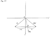
- a vector connecting the two marker coordinate sets is set as the first vector V 1 .
- the second vector V 2 b calculated by the second method may not possibly correspond to the actual inclination of the controller 7 strictly accurately, but usually is not directed in the opposite direction.
- the counter value data 538 is used in the second embodiment, and represents a counter value which indicates the number of frames from the calculation state of the first vector was changed.
- the expression that “the calculation state of the first vector is changed” means that the first vector was calculated previously but is not calculated currently, or the first vector was not calculated previously but is calculated currently.
- the controller 7 it is determined whether to calculate the output vector by the first method or by the second method in accordance with whether or not the controller 7 is in a horizontal direction (a direction close to the horizontal direction).
- the controller 7 is operated, as shown in FIG. 9 , in an area in front of the display screen of the monitor 2 or in the vicinity thereof. Accordingly, in the state where the controller 7 is in a substantially horizontal direction, the controller 7 is in the detectable range. However, in the state where the controller 7 is directed upward or downward, the controller 7 is assumed not to be in the detectable range. In this case, the images of the markers 8 a and 8 b are not taken. Therefore, the first vector cannot be calculated by the first method using the taken image.
Abstract
Description
L1=(ax 2 +ay 2)1/2
hx=−ay/L1
hy=−ax/L1
d1=2−L1
k=d12 ×A
ahx′=(hx−bhx)×k+bhx
ahy′=(hy−bhy)×k+bhy
ahx=ahx′/((ahx′ 2 +ahy′ 2)1/2)
ahy=ahy′/((ahx′ 2 +ahy′ 2)1/2)
L=(ax 2 +ay 2)1/2
S=L (when L≦1)
S=2−L (when 1≦L≦2)
S=0 (when L>2)
Claims (2)
Priority Applications (3)
| Application Number | Priority Date | Filing Date | Title |
|---|---|---|---|
| US12/835,355 US8041536B2 (en) | 2006-03-28 | 2010-07-13 | Inclination calculation apparatus and inclination calculation program, and game apparatus and game program |
| US13/157,063 US8473245B2 (en) | 2006-03-28 | 2011-06-09 | Inclination calculation apparatus and inclination calculation program, and game apparatus and game program |
| US13/899,404 US20130262022A1 (en) | 2006-03-28 | 2013-05-21 | Inclination calculation apparatus and inclination calculation program, and game apparatus and game program |
Applications Claiming Priority (5)
| Application Number | Priority Date | Filing Date | Title |
|---|---|---|---|
| JP2006087160A JP4684147B2 (en) | 2006-03-28 | 2006-03-28 | Inclination calculation device, inclination calculation program, game device, and game program |
| JP2006-087160 | 2006-03-28 | ||
| US11/408,071 US7596466B2 (en) | 2006-03-28 | 2006-04-21 | Inclination calculation apparatus and inclination calculation program, and game apparatus and game program |
| US11/764,409 US7877224B2 (en) | 2006-03-28 | 2007-06-18 | Inclination calculation apparatus and inclination calculation program, and game apparatus and game program |
| US12/835,355 US8041536B2 (en) | 2006-03-28 | 2010-07-13 | Inclination calculation apparatus and inclination calculation program, and game apparatus and game program |
Related Parent Applications (1)
| Application Number | Title | Priority Date | Filing Date |
|---|---|---|---|
| US11/764,409 Continuation US7877224B2 (en) | 2006-03-28 | 2007-06-18 | Inclination calculation apparatus and inclination calculation program, and game apparatus and game program |
Related Child Applications (1)
| Application Number | Title | Priority Date | Filing Date |
|---|---|---|---|
| US13/157,063 Continuation US8473245B2 (en) | 2006-03-28 | 2011-06-09 | Inclination calculation apparatus and inclination calculation program, and game apparatus and game program |
Publications (2)
| Publication Number | Publication Date |
|---|---|
| US20100309117A1 US20100309117A1 (en) | 2010-12-09 |
| US8041536B2 true US8041536B2 (en) | 2011-10-18 |
Family
ID=38120652
Family Applications (5)
| Application Number | Title | Priority Date | Filing Date |
|---|---|---|---|
| US11/408,071 Active US7596466B2 (en) | 2006-03-28 | 2006-04-21 | Inclination calculation apparatus and inclination calculation program, and game apparatus and game program |
| US11/764,409 Active 2026-08-01 US7877224B2 (en) | 2006-03-28 | 2007-06-18 | Inclination calculation apparatus and inclination calculation program, and game apparatus and game program |
| US12/835,355 Active US8041536B2 (en) | 2006-03-28 | 2010-07-13 | Inclination calculation apparatus and inclination calculation program, and game apparatus and game program |
| US13/157,063 Active US8473245B2 (en) | 2006-03-28 | 2011-06-09 | Inclination calculation apparatus and inclination calculation program, and game apparatus and game program |
| US13/899,404 Abandoned US20130262022A1 (en) | 2006-03-28 | 2013-05-21 | Inclination calculation apparatus and inclination calculation program, and game apparatus and game program |
Family Applications Before (2)
| Application Number | Title | Priority Date | Filing Date |
|---|---|---|---|
| US11/408,071 Active US7596466B2 (en) | 2006-03-28 | 2006-04-21 | Inclination calculation apparatus and inclination calculation program, and game apparatus and game program |
| US11/764,409 Active 2026-08-01 US7877224B2 (en) | 2006-03-28 | 2007-06-18 | Inclination calculation apparatus and inclination calculation program, and game apparatus and game program |
Family Applications After (2)
| Application Number | Title | Priority Date | Filing Date |
|---|---|---|---|
| US13/157,063 Active US8473245B2 (en) | 2006-03-28 | 2011-06-09 | Inclination calculation apparatus and inclination calculation program, and game apparatus and game program |
| US13/899,404 Abandoned US20130262022A1 (en) | 2006-03-28 | 2013-05-21 | Inclination calculation apparatus and inclination calculation program, and game apparatus and game program |
Country Status (4)
| Country | Link |
|---|---|
| US (5) | US7596466B2 (en) |
| EP (3) | EP1839714B1 (en) |
| JP (1) | JP4684147B2 (en) |
| DE (3) | DE602006009706D1 (en) |
Cited By (12)
| Publication number | Priority date | Publication date | Assignee | Title |
|---|---|---|---|---|
| US20120295552A1 (en) * | 2008-07-29 | 2012-11-22 | Kyocera Corporation | Mobile device, step counting method, and gravity direction detecting method |
| US8553935B2 (en) | 2006-03-08 | 2013-10-08 | Electronic Scripting Products, Inc. | Computer interface employing a manipulated object with absolute pose detection component and a display |
| US20140121019A1 (en) * | 2007-06-26 | 2014-05-01 | Nintendo Co., Ltd. | Systems and methods for control device including a movement detector |
| US8851996B2 (en) | 2012-08-17 | 2014-10-07 | Microsoft Corporation | Dynamic magnetometer calibration |
| US9229540B2 (en) | 2004-01-30 | 2016-01-05 | Electronic Scripting Products, Inc. | Deriving input from six degrees of freedom interfaces |
| US9849376B2 (en) | 2012-05-02 | 2017-12-26 | Microsoft Technology Licensing, Llc | Wireless controller |
| US9900664B2 (en) | 2015-01-15 | 2018-02-20 | Industrial Technology Research Institute | Method and system for display control, breakaway judging apparatus and video/audio processing apparatus |
| US10118696B1 (en) | 2016-03-31 | 2018-11-06 | Steven M. Hoffberg | Steerable rotating projectile |
| US20190178674A1 (en) * | 2016-08-18 | 2019-06-13 | Sony Corporation | Information processing apparatus, information processing system, and information processing method |
| US10555781B2 (en) * | 2017-11-15 | 2020-02-11 | Stryker Corporation | High bandwidth and low latency hybrid communication techniques for a navigation system |
| US11577159B2 (en) | 2016-05-26 | 2023-02-14 | Electronic Scripting Products Inc. | Realistic virtual/augmented/mixed reality viewing and interactions |
| US11712637B1 (en) | 2018-03-23 | 2023-08-01 | Steven M. Hoffberg | Steerable disk or ball |
Families Citing this family (71)
| Publication number | Priority date | Publication date | Assignee | Title |
|---|---|---|---|---|
| US7749089B1 (en) | 1999-02-26 | 2010-07-06 | Creative Kingdoms, Llc | Multi-media interactive play system |
| US6761637B2 (en) | 2000-02-22 | 2004-07-13 | Creative Kingdoms, Llc | Method of game play using RFID tracking device |
| US7445550B2 (en) | 2000-02-22 | 2008-11-04 | Creative Kingdoms, Llc | Magical wand and interactive play experience |
| US7878905B2 (en) | 2000-02-22 | 2011-02-01 | Creative Kingdoms, Llc | Multi-layered interactive play experience |
| US7066781B2 (en) | 2000-10-20 | 2006-06-27 | Denise Chapman Weston | Children's toy with wireless tag/transponder |
| US6967566B2 (en) | 2002-04-05 | 2005-11-22 | Creative Kingdoms, Llc | Live-action interactive adventure game |
| US20070066396A1 (en) | 2002-04-05 | 2007-03-22 | Denise Chapman Weston | Retail methods for providing an interactive product to a consumer |
| US7674184B2 (en) | 2002-08-01 | 2010-03-09 | Creative Kingdoms, Llc | Interactive water attraction and quest game |
| US9446319B2 (en) | 2003-03-25 | 2016-09-20 | Mq Gaming, Llc | Interactive gaming toy |
| US7927216B2 (en) | 2005-09-15 | 2011-04-19 | Nintendo Co., Ltd. | Video game system with wireless modular handheld controller |
| US8313379B2 (en) | 2005-08-22 | 2012-11-20 | Nintendo Co., Ltd. | Video game system with wireless modular handheld controller |
| JP4262726B2 (en) | 2005-08-24 | 2009-05-13 | 任天堂株式会社 | Game controller and game system |
| US8308563B2 (en) | 2005-08-30 | 2012-11-13 | Nintendo Co., Ltd. | Game system and storage medium having game program stored thereon |
| JP4773170B2 (en) | 2005-09-14 | 2011-09-14 | 任天堂株式会社 | Game program and game system |
| JP5089060B2 (en) | 2006-03-14 | 2012-12-05 | 株式会社ソニー・コンピュータエンタテインメント | Entertainment system and game controller |
| JP4547346B2 (en) * | 2006-03-22 | 2010-09-22 | 任天堂株式会社 | Inclination calculation apparatus, inclination calculation program, game apparatus, and game program |
| US7988558B2 (en) * | 2006-04-27 | 2011-08-02 | Nintendo Co., Ltd. | Game apparatus and storage medium storing game program |
| US7835544B2 (en) * | 2006-08-31 | 2010-11-16 | Avago Technologies General Ip (Singapore) Pte. Ltd. | Method and system for far field image absolute navigation sensing |
| JP5127242B2 (en) * | 2007-01-19 | 2013-01-23 | 任天堂株式会社 | Acceleration data processing program and game program |
| TWI330808B (en) * | 2007-01-23 | 2010-09-21 | Pixart Imaging Inc | Quasi-analog knob controlling method and apparatus using the same |
| JP4918376B2 (en) * | 2007-02-23 | 2012-04-18 | 任天堂株式会社 | Information processing program and information processing apparatus |
| JP5060798B2 (en) * | 2007-02-23 | 2012-10-31 | 任天堂株式会社 | Information processing program and information processing apparatus |
| JP5420824B2 (en) * | 2007-03-30 | 2014-02-19 | 任天堂株式会社 | GAME DEVICE AND GAME PROGRAM |
| JP4916390B2 (en) * | 2007-06-20 | 2012-04-11 | 任天堂株式会社 | Information processing program, information processing apparatus, information processing system, and information processing method |
| TWI338241B (en) * | 2007-08-23 | 2011-03-01 | Pixart Imaging Inc | Interactive image system, interactive device and operative method thereof |
| JP5224832B2 (en) * | 2008-01-21 | 2013-07-03 | 任天堂株式会社 | Information processing program and information processing apparatus |
| US20090206548A1 (en) * | 2008-02-15 | 2009-08-20 | Scott Allan Hawkins | Protective game piece cover and faceplates |
| GB2458297B (en) * | 2008-03-13 | 2012-12-12 | Performance Designed Products Ltd | Pointing device |
| JP2009257974A (en) * | 2008-04-17 | 2009-11-05 | Yamaha Motor Co Ltd | Inclination angle detection device for vehicle, power source control apparatus having it, and vehicle |
| US20110212777A1 (en) * | 2008-04-17 | 2011-09-01 | Power Digital Communications Co., Ltd. | Game device enabling three-dimensional movement |
| US8339366B2 (en) * | 2008-05-09 | 2012-12-25 | International Business Machines Corporation | Game console control to initiate system directives |
| EP2140917B1 (en) | 2008-06-30 | 2018-01-03 | Nintendo Co., Ltd. | Orientation calculation apparatus and storage medium having orientation calculation program stored therein |
| EP2140919B1 (en) * | 2008-06-30 | 2018-09-05 | Nintendo Co., Ltd. | Orientation calculation apparatus, storage medium having orientation calculation program stored therein, game apparatus, and storage medium having game program stored therein |
| EP2140916B1 (en) * | 2008-06-30 | 2018-10-31 | Nintendo Co., Ltd. | Coordinate calculation apparatus and storage medium having coordinate calculation program stored therein |
| US7925467B2 (en) * | 2008-06-30 | 2011-04-12 | Nintendo Co., Ltd. | Orientation calculation apparatus, storage medium having orientation calculation program stored therein, game apparatus, and storage medium having game program stored therein |
| EP2140915B1 (en) | 2008-06-30 | 2019-03-06 | Nintendo Co., Ltd. | Orientation calculation apparatus, storage medium having orientation calculation program stored therein, game apparatus, and storage medium having game program stored therein |
| EP2228109B1 (en) | 2009-03-09 | 2021-03-24 | Nintendo Co., Ltd. | Information processing apparatus, storage medium having information processing program stored therein, information processing system, and display range control method |
| TW201128441A (en) * | 2010-02-01 | 2011-08-16 | Hon Hai Prec Ind Co Ltd | Television system and remote controller thereof and method for selecting program and method for adjusting volume |
| US8217997B2 (en) * | 2010-03-16 | 2012-07-10 | Interphase Corporation | Interactive display system |
| US9955209B2 (en) | 2010-04-14 | 2018-04-24 | Alcatel-Lucent Usa Inc. | Immersive viewer, a method of providing scenes on a display and an immersive viewing system |
| US9294716B2 (en) | 2010-04-30 | 2016-03-22 | Alcatel Lucent | Method and system for controlling an imaging system |
| US20110312417A1 (en) * | 2010-06-17 | 2011-12-22 | Mackay Gordon | Team play game device |
| JP6193928B2 (en) * | 2010-10-26 | 2017-09-06 | 株式会社小糸製作所 | Vehicular lamp control device and vehicle attitude angle information calculation method |
| JP5692904B2 (en) * | 2010-11-17 | 2015-04-01 | 任天堂株式会社 | Input system, information processing apparatus, information processing program, and pointing position calculation method |
| US20120220233A1 (en) * | 2011-02-28 | 2012-08-30 | Qualcomm Incorporated | Ranging with body motion capture |
| US8446364B2 (en) | 2011-03-04 | 2013-05-21 | Interphase Corporation | Visual pairing in an interactive display system |
| US9179182B2 (en) | 2011-04-12 | 2015-11-03 | Kenneth J. Huebner | Interactive multi-display control systems |
| US9504909B2 (en) | 2011-05-05 | 2016-11-29 | Qualcomm Incorporated | Method and apparatus of proximity and stunt recording for outdoor gaming |
| US8641525B2 (en) * | 2011-06-17 | 2014-02-04 | Ironburg Inventions Ltd. | Controller for video game console |
| US9008487B2 (en) | 2011-12-06 | 2015-04-14 | Alcatel Lucent | Spatial bookmarking |
| JP5170715B2 (en) * | 2011-12-27 | 2013-03-27 | 任天堂株式会社 | Information processing program, information processing apparatus, information processing system, and instruction determination method |
| US20140026076A1 (en) * | 2012-07-17 | 2014-01-23 | Jacquilene Jacob | Real-time interactive collaboration system |
| US9235241B2 (en) | 2012-07-29 | 2016-01-12 | Qualcomm Incorporated | Anatomical gestures detection system using radio signals |
| EP2909701A4 (en) | 2012-10-19 | 2016-08-10 | Interphase Corp | Motion compensation in an interactive display system |
| US9159133B2 (en) * | 2012-11-05 | 2015-10-13 | Qualcomm Incorporated | Adaptive scale and/or gravity estimation |
| JP6204686B2 (en) * | 2013-04-12 | 2017-09-27 | 任天堂株式会社 | Information processing program, information processing system, information processing apparatus, and information processing execution method |
| JP6185301B2 (en) | 2013-06-21 | 2017-08-23 | 任天堂株式会社 | Information processing program, information processing apparatus, information processing system, and method for calculating indicated position |
| JP6314394B2 (en) | 2013-09-13 | 2018-04-25 | 富士通株式会社 | Information processing apparatus, setting method, setting program, system, and management apparatus |
| US10838207B2 (en) | 2015-03-05 | 2020-11-17 | Magic Leap, Inc. | Systems and methods for augmented reality |
| WO2016141373A1 (en) | 2015-03-05 | 2016-09-09 | Magic Leap, Inc. | Systems and methods for augmented reality |
| US10180734B2 (en) | 2015-03-05 | 2019-01-15 | Magic Leap, Inc. | Systems and methods for augmented reality |
| KR20180090355A (en) | 2015-12-04 | 2018-08-10 | 매직 립, 인코포레이티드 | Recirculation systems and methods |
| US10255700B2 (en) * | 2016-04-06 | 2019-04-09 | Indiggo Associates LLC | Apparatus and methods for generating data structures to represent and compress data profiles |
| JP7140465B2 (en) * | 2016-06-10 | 2022-09-21 | 任天堂株式会社 | Game program, information processing device, information processing system, game processing method |
| EP3494549A4 (en) | 2016-08-02 | 2019-08-14 | Magic Leap, Inc. | Fixed-distance virtual and augmented reality systems and methods |
| US10812936B2 (en) | 2017-01-23 | 2020-10-20 | Magic Leap, Inc. | Localization determination for mixed reality systems |
| JP7055815B2 (en) | 2017-03-17 | 2022-04-18 | マジック リープ, インコーポレイテッド | A mixed reality system that involves warping virtual content and how to use it to generate virtual content |
| CA3054617A1 (en) | 2017-03-17 | 2018-09-20 | Magic Leap, Inc. | Mixed reality system with multi-source virtual content compositing and method of generating virtual content using same |
| KR102366781B1 (en) | 2017-03-17 | 2022-02-22 | 매직 립, 인코포레이티드 | Mixed reality system with color virtual content warping and method for creating virtual content using same |
| EP3827299A4 (en) | 2018-07-23 | 2021-10-27 | Magic Leap, Inc. | Mixed reality system with virtual content warping and method of generating virtual content using same |
| CN109738358B (en) * | 2018-12-28 | 2021-07-06 | 深圳达闼科技控股有限公司 | Method and device for controlling optical substance detection apparatus, and optical substance detection apparatus |
Citations (245)
| Publication number | Priority date | Publication date | Assignee | Title |
|---|---|---|---|---|
| US3474241A (en) | 1966-10-06 | 1969-10-21 | Jack Kuipers | Coordinate transformer |
| US3660648A (en) | 1969-10-15 | 1972-05-02 | Northrop Corp | Angular rate coordinate transformer |
| US4038876A (en) | 1976-03-04 | 1977-08-02 | Systron Donner Corporation | Acceleration error compensated attitude sensing and control apparatus and method |
| GB1524334A (en) | 1976-03-30 | 1978-09-13 | Itt | Television receiver with an added facility for displaying play symbols an the screen |
| US4402250A (en) | 1979-06-29 | 1983-09-06 | Hollandse Signaalapparaten B.V. | Automatic correction of aiming in firing at moving targets |
| US4558604A (en) | 1981-02-02 | 1985-12-17 | Teldix Gmbh | Directional gyro |
| US4578674A (en) | 1983-04-20 | 1986-03-25 | International Business Machines Corporation | Method and apparatus for wireless cursor position control |
| US4623930A (en) | 1983-12-29 | 1986-11-18 | Matsushita Electric Industrial Co., Ltd. | Camera apparatus |
| US4787051A (en) | 1986-05-16 | 1988-11-22 | Tektronix, Inc. | Inertial mouse system |
| US4839838A (en) | 1987-03-30 | 1989-06-13 | Labiche Mitchell | Spatial input apparatus |
| US4961369A (en) | 1983-01-21 | 1990-10-09 | The Secretary Of State For Defence In Her Britannic Majesty's Government Of The United Kingdom Of Great Britain And Northern Ireland | Gun laying |
| US5045843A (en) | 1988-12-06 | 1991-09-03 | Selectech, Ltd. | Optical pointing device |
| US5059958A (en) | 1990-04-10 | 1991-10-22 | Jacobs Jordan S | Manually held tilt sensitive non-joystick control box |
| US5128671A (en) | 1990-04-12 | 1992-07-07 | Ltv Aerospace And Defense Company | Control device having multiple degrees of freedom |
| US5138154A (en) | 1990-04-04 | 1992-08-11 | Gyration Inc. | Shaft angle encoder with rotating off-axis interference pattern |
| US5181181A (en) | 1990-09-27 | 1993-01-19 | Triton Technologies, Inc. | Computer apparatus input device for three-dimensional information |
| USD342256S (en) | 1991-09-12 | 1993-12-14 | Selectech, Ltd. | Remote control unit |
| US5280744A (en) | 1992-01-27 | 1994-01-25 | Alliedsignal Inc. | Method for aiming towed field artillery pieces |
| US5329276A (en) | 1990-12-19 | 1994-07-12 | Kabushiki Kaisha Yaskawa Denki | Multidimensional signal input device |
| NL9300171A (en) | 1993-01-28 | 1994-08-16 | Josephus Godefridus Wilhelmus | Computer mouse based on a system of acceleration sensors disposed therein |
| US5359348A (en) | 1992-05-21 | 1994-10-25 | Selectech, Ltd. | Pointing device having improved automatic gain control and information reporting |
| US5369889A (en) | 1986-07-07 | 1994-12-06 | Honeywell Inc. | Single gyro northfinder |
| US5373857A (en) | 1993-06-18 | 1994-12-20 | Forte Technologies, Inc. | Head tracking apparatus |
| US5396265A (en) | 1990-09-17 | 1995-03-07 | Massachusetts Institute Of Technology | Three-dimensional tactile computer input device |
| US5421590A (en) | 1993-07-23 | 1995-06-06 | Commodore Electronics Limited | Multiple linked game controllers |
| US5430435A (en) | 1992-11-13 | 1995-07-04 | Rhys Resources | Adjustable athletic training system |
| US5440326A (en) | 1990-03-21 | 1995-08-08 | Gyration, Inc. | Gyroscopic pointer |
| US5453758A (en) | 1992-07-31 | 1995-09-26 | Sony Corporation | Input apparatus |
| US5459489A (en) | 1991-12-05 | 1995-10-17 | Tv Interactive Data Corporation | Hand held electronic remote control device |
| US5481957A (en) | 1992-07-06 | 1996-01-09 | Alliedsignal Inc. | Aiming and pointing system for ground based weapons equipment |
| US5484355A (en) | 1993-10-01 | 1996-01-16 | Smith & Nephew Roylan, Inc. | System for therapeutic exercise and evaluation |
| US5485171A (en) | 1991-10-04 | 1996-01-16 | Micromed Systems, Inc. | Hand held computer input apparatus and method |
| US5506605A (en) | 1992-07-27 | 1996-04-09 | Paley; W. Bradford | Three-dimensional mouse with tactile feedback |
| US5554033A (en) | 1994-07-01 | 1996-09-10 | Massachusetts Institute Of Technology | System for human trajectory learning in virtual environments |
| US5574479A (en) | 1994-01-07 | 1996-11-12 | Selectech, Ltd. | Optical system for determining the roll orientation of a remote unit relative to a base unit |
| US5573011A (en) | 1994-04-08 | 1996-11-12 | Felsing; Gary W. | System for quantifying neurological function |
| US5587558A (en) | 1992-01-24 | 1996-12-24 | Seiko Instruments Inc. | Coordinate detecting apparatus having acceleration detectors |
| US5598187A (en) | 1993-05-13 | 1997-01-28 | Kabushiki Kaisha Toshiba | Spatial motion pattern input system and input method |
| US5602569A (en) | 1994-04-28 | 1997-02-11 | Nintendo Co., Ltd. | Controller for image processing apparatus |
| US5605505A (en) | 1994-02-25 | 1997-02-25 | Lg Electronics Co., Ltd. | Two-player game playing apparatus using wireless remote controllers |
| US5615132A (en) | 1994-01-21 | 1997-03-25 | Crossbow Technology, Inc. | Method and apparatus for determining position and orientation of a moveable object using accelerometers |
| US5627565A (en) | 1994-05-26 | 1997-05-06 | Alps Electric Co., Ltd. | Space coordinates detecting device and input apparatus using same |
| GB2307133A (en) | 1995-11-13 | 1997-05-14 | Secr Defence | Video camera image stabilisation system |
| US5645077A (en) | 1994-06-16 | 1997-07-08 | Massachusetts Institute Of Technology | Inertial orientation tracker apparatus having automatic drift compensation for tracking human head and other similarly sized body |
| DE19701374A1 (en) | 1996-01-17 | 1997-07-24 | Lg Electronics Inc | Hand held wireless three dimensional cursor control, remote control for computer systems, television, robots, computer peripherals |
| DE19701344A1 (en) | 1996-01-17 | 1997-07-24 | Lg Electronics Inc | Hand held wireless three dimensional input unit for computer systems |
| US5679004A (en) | 1995-12-07 | 1997-10-21 | Movit, Inc. | Myoelectric feedback system |
| US5698784A (en) | 1996-01-24 | 1997-12-16 | Gyration, Inc. | Vibratory rate gyroscope and methods of assembly and operation |
| US5703623A (en) | 1996-01-24 | 1997-12-30 | Hall; Malcolm G. | Smart orientation sensing circuit for remote control |
| US5745226A (en) | 1996-11-04 | 1998-04-28 | Litton Systems, Inc. | Passive optical velocity measurement device and method |
| US5757360A (en) | 1995-05-03 | 1998-05-26 | Mitsubishi Electric Information Technology Center America, Inc. | Hand held computer control device |
| DE19648487C1 (en) | 1996-11-12 | 1998-06-10 | Primax Electronics Ltd | Computer mouse with additional display window controls |
| GB2284478B (en) | 1993-11-25 | 1998-07-01 | Alps Electric Co Ltd | Inclination detection apparatus and input apparatus |
| GB2316482B (en) | 1993-11-25 | 1998-07-01 | Alps Electric Co Ltd | Inclination detection apparatus and input apparatus |
| GB2319374B (en) | 1994-11-30 | 1998-07-01 | Alps Electric Co Ltd | Remote coordinate designating device |
| EP0852961A1 (en) | 1997-01-10 | 1998-07-15 | Konami Co., Ltd. | Shooting video game machine |
| US5794081A (en) | 1994-03-03 | 1998-08-11 | Olympus Optical Co., Ltd. | Camera capable of detecting camera shake and compensating image blur due to camera shake |
| US5796354A (en) | 1997-02-07 | 1998-08-18 | Reality Quest Corp. | Hand-attachable controller with direction sensing |
| US5822713A (en) | 1993-04-05 | 1998-10-13 | Contraves Usa | Guided fire control system |
| US5820462A (en) | 1994-08-02 | 1998-10-13 | Nintendo Company Ltd. | Manipulator for game machine |
| DE19814254A1 (en) | 1997-03-31 | 1998-10-15 | Microsoft Corp | Query-based electronic program guide |
| US5825350A (en) | 1996-03-13 | 1998-10-20 | Gyration, Inc. | Electronic pointing apparatus and method |
| US5835156A (en) | 1996-08-14 | 1998-11-10 | Samsung Electroncis, Ltd. | Television graphical user interface employing remote random access pointing device |
| US5835077A (en) | 1995-01-13 | 1998-11-10 | Remec, Inc., | Computer control device |
| US5850624A (en) | 1995-10-18 | 1998-12-15 | The Charles Machine Works, Inc. | Electronic compass |
| RU2125853C1 (en) | 1987-04-29 | 1999-02-10 | Др.Хельмут Хуберти | Device for checking of load on parts of body |
| RU2126161C1 (en) | 1994-06-27 | 1999-02-10 | Коновалов Сергей Феодосьевич | Compensation accelerometer |
| US5875257A (en) | 1997-03-07 | 1999-02-23 | Massachusetts Institute Of Technology | Apparatus for controlling continuous behavior through hand and arm gestures |
| US5897437A (en) | 1995-10-09 | 1999-04-27 | Nintendo Co., Ltd. | Controller pack |
| US5902968A (en) | 1996-02-20 | 1999-05-11 | Ricoh Company, Ltd. | Pen-shaped handwriting input apparatus using accelerometers and gyroscopes and an associated operational device for determining pen movement |
| JP2901476B2 (en) | 1993-12-27 | 1999-06-07 | アルプス電気株式会社 | Position detecting device and position detecting method |
| US5912612A (en) | 1997-10-14 | 1999-06-15 | Devolpi; Dean R. | Multi-speed multi-direction analog pointing device |
| US5955988A (en) | 1996-08-14 | 1999-09-21 | Samsung Electronics Co., Ltd. | Graphical user interface for establishing installation location for satellite based television system |
| US5956035A (en) | 1997-05-15 | 1999-09-21 | Sony Corporation | Menu selection with menu stem and submenu size enlargement |
| US5986644A (en) | 1997-07-30 | 1999-11-16 | Selectech, Ltd. | Remote control system |
| RU2141738C1 (en) | 1994-10-26 | 1999-11-20 | Телефонактиеболагет Лм Эрикссон | Method and device for detection and estimation of movement of mobile sets |
| US6002394A (en) | 1995-10-02 | 1999-12-14 | Starsight Telecast, Inc. | Systems and methods for linking television viewers with advertisers and broadcasters |
| US6013007A (en) | 1998-03-26 | 2000-01-11 | Liquid Spark, Llc | Athlete's GPS-based performance monitor |
| US6016144A (en) | 1996-08-14 | 2000-01-18 | Samsung Electronics Co., Ltd. | Multi-layered television graphical user interface |
| DE19937307A1 (en) | 1998-08-10 | 2000-02-17 | Deutsch Zentr Luft & Raumfahrt | Method for technical control operations using control wheel, where pressure and turning actions are converted into translational and rotational movements of objects being controlled with wheel |
| US6044297A (en) | 1998-09-25 | 2000-03-28 | Medtronic, Inc. | Posture and device orientation and calibration for implantable medical devices |
| US6049823A (en) | 1995-10-04 | 2000-04-11 | Hwang; Ivan Chung-Shung | Multi server, interactive, video-on-demand television system utilizing a direct-access-on-demand workgroup |
| US6052083A (en) | 1998-03-12 | 2000-04-18 | Trimble Navigation Limited | Method and apparatus for position identification |
| US6059576A (en) | 1997-11-21 | 2000-05-09 | Brann; Theodore L. | Training and safety device, system and method to aid in proper movement during physical activity |
| US6069594A (en) | 1991-07-29 | 2000-05-30 | Logitech, Inc. | Computer input device with multiple switches using single line |
| US6072467A (en) | 1996-05-03 | 2000-06-06 | Mitsubishi Electric Information Technology Center America, Inc. (Ita) | Continuously variable control of animated on-screen characters |
| JP3059619B2 (en) | 1993-11-25 | 2000-07-04 | アルプス電気株式会社 | Tilt detecting device and input device using the same |
| US6110039A (en) | 1995-02-21 | 2000-08-29 | Konami Co., Ltd. | Shooting game machine |
| US6115028A (en) | 1996-08-22 | 2000-09-05 | Silicon Graphics, Inc. | Three dimensional input system using tilt |
| JP2000270237A (en) | 1999-03-15 | 2000-09-29 | Nippon Hoso Kyokai <Nhk> | Selector for image display device |
| JP2000308756A (en) | 1999-04-27 | 2000-11-07 | Taito Corp | Input controller of game device |
| US6148100A (en) | 1996-12-20 | 2000-11-14 | Bechtel Bwxt Idaho, Llc | 3-dimensional telepresence system for a robotic environment |
| US6155926A (en) | 1995-11-22 | 2000-12-05 | Nintendo Co., Ltd. | Video game system and method with enhanced three-dimensional character and background control |
| US6164808A (en) | 1996-02-09 | 2000-12-26 | Murata Mfg. Co., Ltd. | Three-dimensional data input device |
| US6176837B1 (en) | 1998-04-17 | 2001-01-23 | Massachusetts Institute Of Technology | Motion tracking system |
| US6181329B1 (en) | 1997-12-23 | 2001-01-30 | Ricoh Company, Ltd. | Method and apparatus for tracking a hand-held writing instrument with multiple sensors that are calibrated by placing the writing instrument in predetermined positions with respect to the writing surface |
| US6184863B1 (en) | 1998-10-13 | 2001-02-06 | The George Washington University | Direct pointing apparatus and method therefor |
| US6191774B1 (en) | 1995-11-17 | 2001-02-20 | Immersion Corporation | Mouse interface for providing force feedback |
| US6198471B1 (en) | 1997-11-07 | 2001-03-06 | Brandt A. Cook | Free-floating multi-axis controller |
| US6222525B1 (en) | 1992-03-05 | 2001-04-24 | Brad A. Armstrong | Image controllers with sheet connected sensors |
| US6241611B1 (en) | 1995-05-10 | 2001-06-05 | Nintendo Co., Ltd. | Function expansion device and operating device using the function expansion device |
| US6243658B1 (en) | 1998-08-14 | 2001-06-05 | Trimble Navigation Limited | Tilt prediction for total station |
| US6244987B1 (en) | 1996-11-25 | 2001-06-12 | Mitsubishi Denki Kabushiki Kaisha | Physical exercise system having a virtual reality environment controlled by a user's movement |
| JP2001159951A (en) | 1999-12-02 | 2001-06-12 | Nec Corp | Information processor and method for processing information |
| JP2001175412A (en) | 1999-12-15 | 2001-06-29 | Shigekazu Koshiba | Remote controller for electronic equipment with multi- axial integral acceleration detector |
| US6264558B1 (en) | 1995-10-09 | 2001-07-24 | Nintendo Co., Ltd. | Video game system with data transmitting/receiving controller |
| JP3194841B2 (en) | 1994-10-24 | 2001-08-06 | アルプス電気株式会社 | Tilt detecting device and input device using the same |
| US6304250B1 (en) | 1997-04-12 | 2001-10-16 | Samsung Electronics Co., Ltd. | Wire/wireless keyboard with pointing device attachable thereto, computer system for use with the same, and related method |
| US6312335B1 (en) | 1997-01-30 | 2001-11-06 | Kabushiki Kaisha Sega Enterprises | Input device, game device, and method and recording medium for same |
| JP3228845B2 (en) | 1995-01-31 | 2001-11-12 | アルプス電気株式会社 | Tilt detector |
| WO2001091042A2 (en) | 2000-05-24 | 2001-11-29 | Infineon Technologies Ag | Positioning unit |
| US6331856B1 (en) | 1995-11-22 | 2001-12-18 | Nintendo Co., Ltd. | Video game system with coprocessor providing high speed efficient 3D graphics and digital audio signal processing |
| DE10029173A1 (en) | 2000-06-19 | 2002-01-03 | Deutsch Zentr Luft & Raumfahrt | Method and arrangement for commanding control operations for kinematic movements of an object using a hand-operated input device |
| US6344791B1 (en) | 1998-07-24 | 2002-02-05 | Brad A. Armstrong | Variable sensor with tactile feedback |
| US6351205B1 (en) | 1996-07-05 | 2002-02-26 | Brad A. Armstrong | Variable-conductance sensor |
| US20020024500A1 (en) | 1997-03-06 | 2002-02-28 | Robert Bruce Howard | Wireless control device |
| JP2002062981A (en) | 2000-08-16 | 2002-02-28 | Nippon Hoso Kyokai <Nhk> | Display screen indicating device |
| JP3262677B2 (en) | 1994-05-02 | 2002-03-04 | 株式会社ワコム | Information input device |
| US20020028071A1 (en) | 2000-07-11 | 2002-03-07 | Claus Molgaard | Digital camera with integrated accelerometers |
| JP2002091692A (en) | 2000-09-12 | 2002-03-29 | Seiko Instruments Inc | Pointing system |
| JP3273531B2 (en) | 1994-11-30 | 2002-04-08 | アルプス電気株式会社 | Remote coordinate pointing device |
| US6369794B1 (en) | 1998-09-09 | 2002-04-09 | Matsushita Electric Industrial Co., Ltd. | Operation indication outputting device for giving operation indication according to type of user's action |
| US6377906B1 (en) | 2000-02-03 | 2002-04-23 | Independence Technology, L.L.C. | Attitude estimation in tiltable body using modified quaternion data representation |
| US6375572B1 (en) | 1999-10-04 | 2002-04-23 | Nintendo Co., Ltd. | Portable game apparatus with acceleration sensor and information storage medium storing a game progam |
| US6377793B1 (en) | 2000-12-06 | 2002-04-23 | Xybernaut Corporation | System and method of accessing and recording messages at coordinate way points |
| US6400996B1 (en) | 1999-02-01 | 2002-06-04 | Steven M. Hoffberg | Adaptive pattern recognition based control system and method |
| US20020075335A1 (en) | 1996-08-05 | 2002-06-20 | Junichi Rekimoto | Information processing device and method |
| US6415223B1 (en) | 1999-11-29 | 2002-07-02 | American Gnc Corporation | Interruption-free hand-held positioning method and system thereof |
| US6421056B1 (en) | 1995-10-09 | 2002-07-16 | Nintendo Co., Ltd. | Three-dimensional image processing apparatus |
| US6424333B1 (en) | 1995-11-30 | 2002-07-23 | Immersion Corporation | Tactile feedback man-machine interface device |
| US20020140745A1 (en) | 2001-01-24 | 2002-10-03 | Ellenby Thomas William | Pointing systems for addressing objects |
| US20020140666A1 (en) | 2001-03-29 | 2002-10-03 | Bradski Gary R. | Intuitive mobile device interface to virtual spaces |
| US6466198B1 (en) | 1999-11-05 | 2002-10-15 | Innoventions, Inc. | View navigation and magnification of a hand-held device with a display |
| US6473713B1 (en) | 1999-09-20 | 2002-10-29 | American Gnc Corporation | Processing method for motion measurement |
| US20020158843A1 (en) | 2001-04-26 | 2002-10-31 | International Business Machines Corporation | Method and adapter for performing assistive motion data processing and/or button data processing external to a computer |
| US6474159B1 (en) | 2000-04-21 | 2002-11-05 | Intersense, Inc. | Motion-tracking |
| US20030038778A1 (en) | 2001-08-13 | 2003-02-27 | Siemens Information And Communication Mobile, Llc | Tilt-based pointing for hand-held devices |
| EP1287864A2 (en) | 2001-08-09 | 2003-03-05 | Konami Corporation | Orientation detection marker, orientation detection device and video game device |
| US20030063068A1 (en) | 1999-11-03 | 2003-04-03 | Anton Suprun E. | Computer input device |
| US6545661B1 (en) | 1999-06-21 | 2003-04-08 | Midway Amusement Games, Llc | Video game system having a control unit with an accelerometer for controlling a video game |
| US6544126B2 (en) | 2000-04-25 | 2003-04-08 | Nintendo Co., Ltd. | Portable game machine with download capability |
| DE10241392A1 (en) | 2001-10-26 | 2003-05-15 | Agilent Technologies Inc | Optical sensor device for sensing relative movement, includes movable motion sensor with two arrays of photo detectors, and multiple lenses that direct far-field images onto arrays of photo detectors |
| US6567536B2 (en) | 2001-02-16 | 2003-05-20 | Golftec Enterprises Llc | Method and system for physical motion analysis |
| US6577350B1 (en) | 1998-12-21 | 2003-06-10 | Sony Corporation | Method and apparatus for displaying an electronic program guide |
| US20030107551A1 (en) | 2001-12-10 | 2003-06-12 | Dunker Garrett Storm | Tilt input device |
| US6582380B2 (en) | 2000-01-24 | 2003-06-24 | Ambulatory Monitoring, Inc. | System and method of monitoring and modifying human activity-based behavior |
| US6590536B1 (en) | 2000-08-18 | 2003-07-08 | Charles A. Walton | Body motion detecting system with correction for tilt of accelerometers and remote measurement of body position |
| US6597443B2 (en) | 2001-06-27 | 2003-07-22 | Duane Boman | Spatial tracking system |
| US6599194B1 (en) | 1998-09-08 | 2003-07-29 | Darren Smith | Home video game system with hard disk drive and internet access capability |
| US6609977B1 (en) | 2000-08-23 | 2003-08-26 | Nintendo Co., Ltd. | External interfaces for a 3D graphics system |
| US6616607B2 (en) | 2000-10-18 | 2003-09-09 | Matsushita Electric Industrial Co., Ltd. | State information acquisition system, state information acquisition apparatus, attachable terminal apparatus, and state information acquisition method |
| US20030193572A1 (en) | 2002-02-07 | 2003-10-16 | Andrew Wilson | System and process for selecting objects in a ubiquitous computing environment |
| US6636826B1 (en) | 1998-12-17 | 2003-10-21 | Nec Tokin Corporation | Orientation angle detector |
| WO2003088147A1 (en) | 2002-04-16 | 2003-10-23 | Koninklijke Philips Electronics N.V. | Image rotation correction for video or photographic equipment |
| US20030204361A1 (en) | 1998-12-09 | 2003-10-30 | Townsend Christopher P. | Solid state orientation sensor with 360 degree measurement capability |
| DE10219198A1 (en) | 2002-04-29 | 2003-11-06 | Univ Leipzig | Cursor movement control device comprises a device that is moved in space so that sensors, such as acceleration sensors, detect the movement which is converted into a command signal that is transmitted to a computer or similar |
| US20030216176A1 (en) | 2002-05-20 | 2003-11-20 | Takao Shimizu | Game system and game program |
| US20030222851A1 (en) | 2002-06-04 | 2003-12-04 | Cheng-Shing Lai | Computer pointing device employing a magnetic field source and magnetic field sensors |
| WO2003107260A2 (en) | 2002-06-14 | 2003-12-24 | Siemens Aktiengesellschaft | Input device for a data processing system |
| US6672962B1 (en) | 1998-05-13 | 2004-01-06 | Kabushiki Kaisha Sega Enterprises | Gun-shaped controller and game device |
| US6679776B1 (en) | 1997-07-17 | 2004-01-20 | Nintendo Co., Ltd. | Video game system |
| US6686954B1 (en) | 1998-06-26 | 2004-02-03 | Ricoh Company, Ltd. | Apparatus and method for correction of a deviation of digital camera |
| WO2004012130A1 (en) | 2002-07-25 | 2004-02-05 | Andamiro Co., Ltd. | Shooting game machine and method for performing it |
| US20040028258A1 (en) | 2002-08-09 | 2004-02-12 | Leonid Naimark | Fiducial detection system |
| JP2004062774A (en) | 2002-07-31 | 2004-02-26 | Sharp Corp | Presentation display device |
| US6712692B2 (en) | 2002-01-03 | 2004-03-30 | International Business Machines Corporation | Using existing videogames for physical training and rehabilitation |
| US6717573B1 (en) | 1998-06-23 | 2004-04-06 | Immersion Corporation | Low-cost haptic mouse implementations |
| JP3517482B2 (en) | 1995-06-08 | 2004-04-12 | キヤノン株式会社 | Coordinate detection device and method |
| US20040070564A1 (en) | 2002-10-15 | 2004-04-15 | Dawson Thomas P. | Method and system for controlling a display device |
| US6725173B2 (en) | 2000-09-02 | 2004-04-20 | American Gnc Corporation | Digital signal processing method and system thereof for precision orientation measurements |
| US20040075650A1 (en) | 1999-05-25 | 2004-04-22 | Lapstun Paul | Orientation sensing device with processor |
| US20040095317A1 (en) | 2002-11-20 | 2004-05-20 | Jingxi Zhang | Method and apparatus of universal remote pointing control for home entertainment system and computer |
| WO2004051391A2 (en) | 2002-11-27 | 2004-06-17 | Commissariat A L'energie Atomique | Method and device for capturing the movement of a solid using at least one camera and one angular sensor |
| US6753849B1 (en) | 1999-10-27 | 2004-06-22 | Ken Curran & Associates | Universal remote TV mouse |
| US6757068B2 (en) | 2000-01-28 | 2004-06-29 | Intersense, Inc. | Self-referenced tracking |
| US6757446B1 (en) | 2000-11-27 | 2004-06-29 | Microsoft Corporation | System and process for image-based relativistic rendering |
| US20040134341A1 (en) | 2001-04-27 | 2004-07-15 | Stephane Sandoz | Device, and related method, for determining the direction of a target |
| US20040143413A1 (en) | 2002-07-22 | 2004-07-22 | Raytheon Company | System for measuring the effect of bearing errors in an active device |
| US20040140954A1 (en) | 2003-01-14 | 2004-07-22 | Faeth Michael Gene | Two handed computer input device |
| WO2004066615A1 (en) | 2003-01-22 | 2004-08-05 | Nokia Corporation | Image control |
| US20040193413A1 (en) | 2003-03-25 | 2004-09-30 | Wilson Andrew D. | Architecture for controlling a computer using hand gestures |
| US20040204240A1 (en) | 2000-02-22 | 2004-10-14 | Barney Jonathan A. | Magical wand and interactive play experience |
| US6811489B1 (en) | 2000-08-23 | 2004-11-02 | Nintendo Co., Ltd. | Controller interface for a graphics system |
| US6813584B2 (en) | 2001-03-30 | 2004-11-02 | Tsinghua University | Micro azimuth-level detector based on micro electro-mechanical systems and a method for determination of attitude |
| US20040218104A1 (en) | 2003-05-01 | 2004-11-04 | Smith Gregory C. | Multimedia user interface |
| US20040227725A1 (en) | 2002-10-14 | 2004-11-18 | Stmicroelectronics S.R.L. | User controlled device for sending control signals to an electric appliance, in particular user controlled pointing device such as mouse of joystick, with 3D-motion detection |
| US20040229693A1 (en) | 2003-05-13 | 2004-11-18 | Clifton Lind | Multiple video display gaming machine and gaming system |
| US20040259651A1 (en) | 2002-09-27 | 2004-12-23 | Imego Ab | Sporting equipment provided with a motion detecting arrangement |
| US20040268393A1 (en) | 2003-05-08 | 2004-12-30 | Hunleth Frank A. | Control framework with a zoomable graphical user interface for organizing, selecting and launching media items |
| US6836971B1 (en) | 2003-07-30 | 2005-01-04 | Honeywell International Inc. | System for using a 2-axis magnetic sensor for a 3-axis compass solution |
| US6842991B2 (en) | 2002-07-31 | 2005-01-18 | Robert W. Levi | Gyro aided magnetic compass |
| US20050020369A1 (en) | 2003-07-22 | 2005-01-27 | Craig Davis | Golf club with embedded inertial measurement unit and processing |
| US6850844B1 (en) | 2002-06-28 | 2005-02-01 | Garmin Ltd. | Portable navigation device with integrated GPS and dead reckoning capabilities |
| US20050054457A1 (en) | 2003-09-08 | 2005-03-10 | Smartswing, Inc. | Method and system for golf swing analysis and training |
| US6873406B1 (en) | 2002-01-11 | 2005-03-29 | Opti-Logic Corporation | Tilt-compensated laser rangefinder |
| US6872139B2 (en) | 2000-08-23 | 2005-03-29 | Nintendo Co., Ltd. | Information processing system |
| US20050076161A1 (en) | 2003-10-03 | 2005-04-07 | Amro Albanna | Input system and method |
| US6906700B1 (en) | 1992-03-05 | 2005-06-14 | Anascape | 3D controller with vibration |
| US6922632B2 (en) | 2002-08-09 | 2005-07-26 | Intersense, Inc. | Tracking, auto-calibration, and map-building system |
| US20050174324A1 (en) | 2003-10-23 | 2005-08-11 | Hillcrest Communications, Inc. | User interface devices and methods employing accelerometers |
| US6929548B2 (en) | 2002-04-23 | 2005-08-16 | Xiaoling Wang | Apparatus and a method for more realistic shooting video games on computers or similar devices |
| US20050212752A1 (en) | 2004-03-23 | 2005-09-29 | Marvit David L | Selective engagement of motion input modes |
| US20050212767A1 (en) | 2004-03-23 | 2005-09-29 | Marvit David L | Context dependent gesture response |
| US20050243061A1 (en) | 2004-04-30 | 2005-11-03 | Hillcrest Communications, Inc. | Methods and devices for identifying users based on tremor |
| US20050256675A1 (en) | 2002-08-28 | 2005-11-17 | Sony Corporation | Method and device for head tracking |
| US20050253806A1 (en) | 2004-04-30 | 2005-11-17 | Hillcrest Communications, Inc. | Free space pointing devices and methods |
| US6984208B2 (en) | 2002-08-01 | 2006-01-10 | The Hong Kong Polytechnic University | Method and apparatus for sensing body gesture, posture and movement |
| US6990639B2 (en) | 2002-02-07 | 2006-01-24 | Microsoft Corporation | System and process for controlling electronic components in a ubiquitous computing environment using multimodal integration |
| US20060028446A1 (en) | 2004-04-30 | 2006-02-09 | Hillcrest Communications, Inc. | Methods and devices for removing unintentional movement in free space pointing devices |
| US6998966B2 (en) | 2003-11-26 | 2006-02-14 | Nokia Corporation | Mobile communication device having a functional cover for controlling sound applications by motion |
| US7002591B1 (en) | 2000-08-23 | 2006-02-21 | Nintendo Co., Ltd. | Method and apparatus for interleaved processing of direct and indirect texture coordinates in a graphics system |
| US7000469B2 (en) | 2000-04-21 | 2006-02-21 | Intersense, Inc. | Motion-tracking |
| JP2006113019A (en) | 2004-10-18 | 2006-04-27 | Alps Electric Co Ltd | Triaxial type electronic compass, and azimuth detecting method using same |
| US20060092133A1 (en) | 2004-11-02 | 2006-05-04 | Pierre A. Touma | 3D mouse and game controller based on spherical coordinates system and system for use |
| US20060148563A1 (en) | 2005-01-04 | 2006-07-06 | Pixart Imaging Inc. | Gaming peripheral apparatus for a gaming computing device |
| US20060152488A1 (en) | 2005-01-12 | 2006-07-13 | Kenneth Salsman | Electronic equipment for handheld vision based absolute pointing system |
| US20060178212A1 (en) | 2004-11-23 | 2006-08-10 | Hillcrest Laboratories, Inc. | Semantic gaming and application transformation |
| US7098894B2 (en) | 2000-12-15 | 2006-08-29 | Finger System Inc. | Pen type optical mouse device and method of controlling the same |
| US7098891B1 (en) | 1992-09-18 | 2006-08-29 | Pryor Timothy R | Method for providing human input to a computer |
| US7102616B1 (en) | 1999-03-05 | 2006-09-05 | Microsoft Corporation | Remote control device with pointing capacity |
| US7126584B1 (en) | 1995-10-09 | 2006-10-24 | Nintendo Co., Ltd. | Operating device and image processing system using same |
| US7127370B2 (en) | 2000-01-07 | 2006-10-24 | Nocwatch International Inc. | Attitude indicator and activity monitoring device |
| US20060256081A1 (en) | 2002-07-27 | 2006-11-16 | Sony Computer Entertainment America Inc. | Scheme for detecting and tracking user manipulation of a game controller body |
| US7139983B2 (en) | 2000-04-10 | 2006-11-21 | Hillcrest Laboratories, Inc. | Interactive content guide for television programming |
| US20060264260A1 (en) | 2002-07-27 | 2006-11-23 | Sony Computer Entertainment Inc. | Detectable and trackable hand-held controller |
| US7149627B2 (en) | 2002-03-01 | 2006-12-12 | Gentex Corporation | Electronic compass system |
| US20060282873A1 (en) | 2002-07-27 | 2006-12-14 | Sony Computer Entertainment Inc. | Hand-held controller having detectable elements for tracking purposes |
| US20060287087A1 (en) | 2002-07-27 | 2006-12-21 | Sony Computer Entertainment America Inc. | Method for mapping movements of a hand-held controller to game commands |
| US20060287086A1 (en) | 2002-07-27 | 2006-12-21 | Sony Computer Entertainment America Inc. | Scheme for translating movements of a hand-held controller into inputs for a system |
| US7154475B2 (en) | 2002-11-28 | 2006-12-26 | Cylo Technology Pty Ltd | Computer mouse with magnetic orientation features |
| US7158118B2 (en) | 2004-04-30 | 2007-01-02 | Hillcrest Laboratories, Inc. | 3D pointing devices with orientation compensation and improved usability |
| US7173604B2 (en) | 2004-03-23 | 2007-02-06 | Fujitsu Limited | Gesture identification of controlled devices |
| US7176919B2 (en) | 2000-08-23 | 2007-02-13 | Nintendo Co., Ltd. | Recirculating shade tree blender for a graphics system |
| US7182691B1 (en) | 2000-09-28 | 2007-02-27 | Immersion Corporation | Directional inertial tactile feedback using rotating masses |
| US7183480B2 (en) | 2000-01-11 | 2007-02-27 | Yamaha Corporation | Apparatus and method for detecting performer's motion to interactively control performance of music or the like |
| US7184059B1 (en) | 2000-08-23 | 2007-02-27 | Nintendo Co., Ltd. | Graphics system with copy out conversions between embedded frame buffer and main memory |
| US7220220B2 (en) | 1999-11-09 | 2007-05-22 | Stubbs Jack B | Exercise monitoring system and methods |
| US20070252815A1 (en) | 2006-04-26 | 2007-11-01 | Pixart Imaging, Inc. | Interactive game apparatus and game controller used in the same |
| US7292151B2 (en) | 2004-07-29 | 2007-11-06 | Kevin Ferguson | Human movement measurement system |
| US20070265076A1 (en) | 2006-04-26 | 2007-11-15 | Pixart Imaging Inc. | Interactive wireless game apparatus and wireless peripheral module |
| US7301527B2 (en) | 2004-03-23 | 2007-11-27 | Fujitsu Limited | Feedback based user interface for motion controlled handheld devices |
| US7335134B1 (en) | 2004-02-23 | 2008-02-26 | Lavelle Richard | Exercise and game controller apparatus and method |
| US7445550B2 (en) | 2000-02-22 | 2008-11-04 | Creative Kingdoms, Llc | Magical wand and interactive play experience |
| US20080273011A1 (en) | 2007-05-03 | 2008-11-06 | Pixart Imagining Incorporation | Interactive game method and system with sports injury protection |
| US20080278445A1 (en) | 2007-05-08 | 2008-11-13 | Thinkoptics, Inc. | Free-space multi-dimensional absolute pointer with improved performance |
Family Cites Families (124)
| Publication number | Priority date | Publication date | Assignee | Title |
|---|---|---|---|---|
| US342256A (en) * | 1886-05-18 | gornall | ||
| US4285523A (en) | 1978-11-06 | 1981-08-25 | Lemelson Jerome H | Game aiming device securable to television receiver cabinet |
| JPS59148287A (en) | 1983-02-14 | 1984-08-24 | 日本電気株式会社 | Connector |
| US4739128A (en) | 1986-11-10 | 1988-04-19 | American Telephone And Telegraph Company, At&T Bell Laboratories | Thumb-controlled, hand-held joystick |
| WO1988004060A2 (en) | 1986-11-27 | 1988-06-02 | Starpeak Computers Limited | Locating system |
| US4816810A (en) | 1987-08-28 | 1989-03-28 | Moore Robert F | Remote acceptance switch for computer mouse |
| US4862165A (en) | 1988-02-12 | 1989-08-29 | Samuel Gart | Ergonomically-shaped hand controller |
| US4994795A (en) | 1988-12-08 | 1991-02-19 | Mackenzie Kirk F | Position indicating device for a digital computer |
| US5089958A (en) * | 1989-01-23 | 1992-02-18 | Vortex Systems, Inc. | Fault tolerant computer backup system |
| USD320624S (en) | 1989-05-26 | 1991-10-08 | Atari Corporation | Hand-held electronic game apparatus housing |
| US4969647A (en) | 1989-06-02 | 1990-11-13 | Atari Corporation | Invertible hand-held electronic game apparatus |
| USD325225S (en) | 1989-06-19 | 1992-04-07 | Nintendo Company Limited | Hand held controller for a video game machine |
| USD322242S (en) | 1989-11-27 | 1991-12-10 | Nintendo Of America, Inc. | Remote control transmitter |
| GB2241629A (en) | 1990-02-27 | 1991-09-04 | Apple Computer | Content-based depictions of computer icons |
| USD331058S (en) | 1990-08-08 | 1992-11-17 | Tv Answer, Inc. | TV remote control unit |
| JPH0442029U (en) | 1990-08-09 | 1992-04-09 | ||
| US5192082A (en) | 1990-08-24 | 1993-03-09 | Nintendo Company Limited | TV game machine |
| US5119079A (en) | 1990-09-17 | 1992-06-02 | Xerox Corporation | Touch screen user interface with expanding touch locations for a reprographic machine |
| USD328463S (en) | 1990-11-08 | 1992-08-04 | Konica Technology, Inc. | Remote control unit |
| US5080604A (en) | 1990-11-13 | 1992-01-14 | Amp Incorporated | Self-aligning electrical connector assembly for flat power cable terminations |
| US5332322A (en) | 1991-06-06 | 1994-07-26 | Gambaro Thomas L | Ergonomic thumb-actuable keyboard for a hand-grippable device |
| US5178477A (en) | 1991-06-06 | 1993-01-12 | Gambaro Thomas L | Ergonomic keyboard input device |
| JPH0580925A (en) * | 1991-09-19 | 1993-04-02 | Hitachi Ltd | Pointing device for large-screen display |
| US5903454A (en) | 1991-12-23 | 1999-05-11 | Hoffberg; Linda Irene | Human-factored interface corporating adaptive pattern recognition based controller apparatus |
| USD345164S (en) | 1991-12-30 | 1994-03-15 | Grae Bernard A | Hand controller for multimedia video system |
| JP3037818B2 (en) | 1992-02-28 | 2000-05-08 | 株式会社ハドソン | A method for correcting color unevenness in color images |
| USD338242S (en) | 1992-03-12 | 1993-08-10 | Nintendo Of America, Inc. | Video game control module |
| US5981883A (en) | 1992-07-08 | 1999-11-09 | Lci Technology Group, N.V. | Systems for imaging written information |
| US5551701A (en) | 1992-08-19 | 1996-09-03 | Thrustmaster, Inc. | Reconfigurable video game controller with graphical reconfiguration display |
| US5259626A (en) | 1992-08-07 | 1993-11-09 | Std Electronic International Ltd. | Programmable video game controller |
| TW371340B (en) * | 1992-10-09 | 1999-10-01 | Hudson Soft Co Ltd | Image processing system |
| USD351430S (en) | 1993-03-08 | 1994-10-11 | Nintendo Co., Ltd. | Controller for video game machine |
| USD350782S (en) | 1993-05-24 | 1994-09-20 | Nintendo Of America Inc. | Controller for video game machine |
| USD360903S (en) | 1993-06-28 | 1995-08-01 | Nintendo Company, Ltd. | Controller for a video game machine |
| JP2610386B2 (en) | 1993-09-28 | 1997-05-14 | 株式会社ハドソン | Camera with monitor |
| US5563628A (en) | 1993-10-12 | 1996-10-08 | Stroop; Jeffrey A. | Hand held computer cursor controller and command input device |
| US5523800A (en) | 1993-11-04 | 1996-06-04 | Dudek; Walter J. | Programmable alpha/numeric channel entry translation function for hand held video remote controls |
| AU122125S (en) | 1994-02-08 | 1994-12-07 | Sega Enterprises Kk | Video game machine |
| US5512892A (en) | 1994-02-25 | 1996-04-30 | International Business Machines Corporation | Hand held control device |
| JPH07303290A (en) | 1994-05-02 | 1995-11-14 | Wacom Co Ltd | Information input device |
| USD375326S (en) | 1994-05-02 | 1996-11-05 | Nintendo Co., Ltd. | Controller for game machine |
| US6004134A (en) | 1994-05-19 | 1999-12-21 | Exos, Inc. | Interactive simulation including force feedback |
| US5528265A (en) | 1994-07-18 | 1996-06-18 | Harrison; Simon J. | Orientation-operated cursor control device |
| JP3603285B2 (en) | 1994-07-21 | 2004-12-22 | 株式会社セガ | Image processing device |
| US5642279A (en) | 1994-08-09 | 1997-06-24 | New England Audio Company | Technique for utilizing a computer system to provide price protection to retail customers |
| USD397162S (en) | 1994-11-11 | 1998-08-18 | Nintendo Of America, Inc. | Controller for game machine |
| US5754854A (en) * | 1994-11-14 | 1998-05-19 | Microsoft Corporation | Method and system for providing a group of parallel resources as a proxy for a single shared resource |
| CN2211084Y (en) | 1994-11-15 | 1995-10-25 | 郑秋豪 | Split-type keyboard of television game-machine |
| USD376826S (en) | 1994-12-19 | 1996-12-24 | Nintendo Of America, Inc. | Controller for game machine |
| JP2766204B2 (en) | 1994-12-22 | 1998-06-18 | アルプス電気株式会社 | Operation device for game machine |
| USD379832S (en) | 1995-01-31 | 1997-06-10 | Nintendo Of America, Inc. | Game machine |
| EP0807352A1 (en) * | 1995-01-31 | 1997-11-19 | Transcenic, Inc | Spatial referenced photography |
| US5677708A (en) | 1995-05-05 | 1997-10-14 | Microsoft Corporation | System for displaying a list on a display screen |
| GB2300503A (en) | 1995-05-05 | 1996-11-06 | United Microelectronics Corp | Video game with display of key programming process |
| US5913727A (en) | 1995-06-02 | 1999-06-22 | Ahdoot; Ned | Interactive movement and contact simulation game |
| US5724106A (en) | 1995-07-17 | 1998-03-03 | Gateway 2000, Inc. | Hand held remote control device with trigger button |
| US5900867A (en) | 1995-07-17 | 1999-05-04 | Gateway 2000, Inc. | Self identifying remote control device having a television receiver for use in a computer |
| US5702323A (en) | 1995-07-26 | 1997-12-30 | Poulton; Craig K. | Electronic exercise enhancer |
| US5670988A (en) | 1995-09-05 | 1997-09-23 | Interlink Electronics, Inc. | Trigger operated electronic device |
| US5898435A (en) | 1995-10-02 | 1999-04-27 | Sony Corporation | Image controlling device and image controlling method |
| TW355774B (en) | 1995-10-12 | 1999-04-11 | Konami Co Ltd | TV game device, its loading support method and control method |
| US5793438A (en) | 1995-11-13 | 1998-08-11 | Hyundai Electronics America | Electronic program guide with enhanced presentation |
| US6127990A (en) * | 1995-11-28 | 2000-10-03 | Vega Vista, Inc. | Wearable display and methods for controlling same |
| JP3709447B2 (en) | 1996-03-29 | 2005-10-26 | 株式会社セガ | Tablet unit |
| FR2747518B1 (en) | 1996-04-12 | 1998-06-05 | Framatome Connectors France | SHIELDED CONNECTOR OF THE TYPE COMPRISING A PLUG AND A BASE AND PROVIDED WITH A LOCKING/UNLOCKING DEVICE |
| US5947819A (en) * | 1996-05-22 | 1999-09-07 | Konami Co., Ltd. | Object-throwing video game system |
| USD395464S (en) | 1996-07-01 | 1998-06-23 | Namco, Ltd. | Steering wheel for a video game machine |
| US6128002A (en) * | 1996-07-08 | 2000-10-03 | Leiper; Thomas | System for manipulation and display of medical images |
| US5989157A (en) | 1996-08-06 | 1999-11-23 | Walton; Charles A. | Exercising system with electronic inertial game playing |
| USD393884S (en) | 1996-10-08 | 1998-04-28 | Matsushita Electric Industrial Co., Ltd. | TV game machine |
| US6177931B1 (en) * | 1996-12-19 | 2001-01-23 | Index Systems, Inc. | Systems and methods for displaying and recording control interface with television programs, video, advertising information and program scheduling information |
| JP2961097B2 (en) * | 1997-01-10 | 1999-10-12 | コナミ株式会社 | Shooting video game device |
| TW356730U (en) * | 1997-06-14 | 1999-04-21 | Top Game & Company Ltd | Operation apparatus for game machine |
| USD407761S (en) | 1997-08-18 | 1999-04-06 | Nintendo Co. Ltd. | Game machine |
| US6172674B1 (en) * | 1997-08-25 | 2001-01-09 | Liberate Technologies | Smart filtering |
| US5990890A (en) | 1997-08-25 | 1999-11-23 | Liberate Technologies | System for data entry and navigation in a user interface |
| US6018372A (en) * | 1997-09-04 | 2000-01-25 | Liberate Technologies | Electronic program guide with multiple day planner |
| USD402328S (en) | 1997-10-16 | 1998-12-08 | Nintendo Co., Ltd. | Magnetic disk drive for game machine |
| USD405071S (en) | 1997-10-17 | 1999-02-02 | Gambaro Thomas L | Cursor control--data entry device |
| FR2770317B1 (en) * | 1997-10-24 | 2000-12-08 | Commissariat Energie Atomique | METHOD FOR CALIBRATING THE ORIGINAL POSITION AND ORIENTATION OF ONE OR MORE MOBILE CAMERAS AND ITS APPLICATION TO MEASURING THE THREE-DIMENSIONAL POSITION OF FIXED OBJECTS |
| US5971790A (en) | 1997-10-31 | 1999-10-26 | The Whitaker Corporation | Unitary spring latch for an electrical connector assembly |
| US6211856B1 (en) * | 1998-04-17 | 2001-04-03 | Sung M. Choi | Graphical user interface touch screen with an auto zoom feature |
| USD412940S (en) | 1998-05-14 | 1999-08-17 | Sega Enterprises, Ltd. | Video game machine |
| EP1104199A4 (en) * | 1998-07-03 | 2008-04-02 | Hudson Co Ltd | Image coding/decoding method and recorded medium on which program is recorded |
| EP1116211A4 (en) * | 1998-09-22 | 2001-11-21 | Vega Vista Inc | Intuitive control of portable data displays |
| JP2000097637A (en) * | 1998-09-24 | 2000-04-07 | Olympus Optical Co Ltd | Attitude position detecting device |
| GB2362479B (en) * | 1998-12-24 | 2003-01-15 | Mitsubishi Electric Corp | Numerical control device |
| USD419200S (en) | 1999-04-14 | 2000-01-18 | Nintendo Of America Inc. | Game machine and disk drive stack |
| USD419199S (en) | 1999-04-14 | 2000-01-18 | Nintendo Of America Inc. | Game machine and console stack |
| JP2000350864A (en) * | 1999-06-10 | 2000-12-19 | Konami Co Ltd | Portable type game machine and game progress method |
| JP2001009152A (en) * | 1999-06-30 | 2001-01-16 | Konami Co Ltd | Game system and storage medium readable by computer |
| US6727885B1 (en) * | 1999-09-07 | 2004-04-27 | Nikon Corporation | Graphical user interface and position or attitude detector |
| US6857128B1 (en) * | 2000-02-14 | 2005-02-15 | Sharp Laboratories Of America | Electronic programming guide browsing system |
| US6535114B1 (en) * | 2000-03-22 | 2003-03-18 | Toyota Jidosha Kabushiki Kaisha | Method and apparatus for environment recognition |
| US6744420B2 (en) * | 2000-06-01 | 2004-06-01 | Olympus Optical Co., Ltd. | Operation input apparatus using sensor attachable to operator's hand |
| USD456410S1 (en) * | 2000-08-11 | 2002-04-30 | Nintendo Co., Ltd. | Controller for electronic game machine |
| US20080060011A1 (en) * | 2000-12-22 | 2008-03-06 | Hillcrest Laboratories, Inc. | Zoomable user interfaces for television |
| USD473942S1 (en) * | 2001-04-27 | 2003-04-29 | Olympus Optical Co., Ltd. | Remote control apparatus for industrial endoscope |
| KR100446613B1 (en) * | 2001-07-16 | 2004-09-04 | 삼성전자주식회사 | Information input method using wearable information input device |
| US6544124B2 (en) * | 2001-08-29 | 2003-04-08 | Radica China Ltd. | Handheld steering wheel game controller |
| JP4028708B2 (en) * | 2001-10-19 | 2007-12-26 | 株式会社コナミデジタルエンタテインメント | GAME DEVICE AND GAME SYSTEM |
| US7854655B2 (en) * | 2002-07-27 | 2010-12-21 | Sony Computer Entertainment America Inc. | Obtaining input for controlling execution of a game program |
| US6908191B2 (en) * | 2002-07-31 | 2005-06-21 | Eastman Kodak Company | Ink jet printing method |
| USD502468S1 (en) * | 2002-07-31 | 2005-03-01 | British Sky Broadcasting Ltd. | Game controller |
| US20050044509A1 (en) * | 2003-05-07 | 2005-02-24 | Hunleth Frank A. | Item selection using helical menus |
| US8555165B2 (en) * | 2003-05-08 | 2013-10-08 | Hillcrest Laboratories, Inc. | Methods and systems for generating a zoomable graphical user interface |
| WO2004111819A1 (en) * | 2003-06-09 | 2004-12-23 | Immersion Corporation | Interactive gaming systems with haptic feedback |
| JP2005107247A (en) * | 2003-09-30 | 2005-04-21 | Canon Inc | Method and device for estimating positional attitude |
| JP2005106664A (en) * | 2003-09-30 | 2005-04-21 | Mitsubishi Electric Corp | Acceleration sensing device and crew protection system using the same |
| JP4420739B2 (en) * | 2004-05-25 | 2010-02-24 | シャープ株式会社 | Projection type image display device |
| US7484184B2 (en) * | 2004-07-20 | 2009-01-27 | Hillcrest Laboratories, Inc. | Graphical cursor navigation methods |
| JP4494251B2 (en) * | 2004-07-26 | 2010-06-30 | 富士通コンポーネント株式会社 | Connector unit for balanced transmission |
| JP4127256B2 (en) | 2004-09-14 | 2008-07-30 | 松下電器産業株式会社 | SOC measurement method for lead acid battery |
| US7014490B1 (en) * | 2005-02-25 | 2006-03-21 | Yazaki Corporation | USB connector equipped with lock mechanism |
| WO2006127596A2 (en) * | 2005-05-20 | 2006-11-30 | Hillcrest Laboratories, Inc. | Dynamic hyperlinking approach |
| CN101213774B (en) * | 2005-07-01 | 2012-01-04 | 希尔克瑞斯特实验室公司 | 3D positioning devices |
| JP4933164B2 (en) * | 2005-07-01 | 2012-05-16 | キヤノン株式会社 | Information processing apparatus, information processing method, program, and storage medium |
| FR2889338B1 (en) * | 2005-07-26 | 2007-10-05 | Alessandro Manneschi | DETECTOR OF UNAUTHORIZED OBJECTS IN A PROTECTED ACCESS AREA |
| US20070067798A1 (en) * | 2005-08-17 | 2007-03-22 | Hillcrest Laboratories, Inc. | Hover-buttons for user interfaces |
| JP4805633B2 (en) * | 2005-08-22 | 2011-11-02 | 任天堂株式会社 | Game operation device |
| JP4262726B2 (en) * | 2005-08-24 | 2009-05-13 | 任天堂株式会社 | Game controller and game system |
| US8308563B2 (en) * | 2005-08-30 | 2012-11-13 | Nintendo Co., Ltd. | Game system and storage medium having game program stored thereon |
| US8708822B2 (en) * | 2005-09-01 | 2014-04-29 | Nintendo Co., Ltd. | Information processing system and program |
| CN101558647A (en) * | 2006-08-29 | 2009-10-14 | 希尔克瑞斯特实验室公司 | Television control, playlist generation and DVR systems and methods |
-
2006
- 2006-03-28 JP JP2006087160A patent/JP4684147B2/en active Active
- 2006-04-20 EP EP06008201A patent/EP1839714B1/en active Active
- 2006-04-20 EP EP08010550A patent/EP1964595B1/en active Active
- 2006-04-20 DE DE602006009706T patent/DE602006009706D1/en active Active
- 2006-04-20 EP EP08010551A patent/EP1967239B1/en active Active
- 2006-04-20 DE DE602006010904T patent/DE602006010904D1/en active Active
- 2006-04-20 DE DE602006009620T patent/DE602006009620D1/en active Active
- 2006-04-21 US US11/408,071 patent/US7596466B2/en active Active
-
2007
- 2007-06-18 US US11/764,409 patent/US7877224B2/en active Active
-
2010
- 2010-07-13 US US12/835,355 patent/US8041536B2/en active Active
-
2011
- 2011-06-09 US US13/157,063 patent/US8473245B2/en active Active
-
2013
- 2013-05-21 US US13/899,404 patent/US20130262022A1/en not_active Abandoned
Patent Citations (287)
| Publication number | Priority date | Publication date | Assignee | Title |
|---|---|---|---|---|
| US3474241A (en) | 1966-10-06 | 1969-10-21 | Jack Kuipers | Coordinate transformer |
| US3660648A (en) | 1969-10-15 | 1972-05-02 | Northrop Corp | Angular rate coordinate transformer |
| US4038876A (en) | 1976-03-04 | 1977-08-02 | Systron Donner Corporation | Acceleration error compensated attitude sensing and control apparatus and method |
| GB1524334A (en) | 1976-03-30 | 1978-09-13 | Itt | Television receiver with an added facility for displaying play symbols an the screen |
| US4402250A (en) | 1979-06-29 | 1983-09-06 | Hollandse Signaalapparaten B.V. | Automatic correction of aiming in firing at moving targets |
| US4558604A (en) | 1981-02-02 | 1985-12-17 | Teldix Gmbh | Directional gyro |
| US4961369A (en) | 1983-01-21 | 1990-10-09 | The Secretary Of State For Defence In Her Britannic Majesty's Government Of The United Kingdom Of Great Britain And Northern Ireland | Gun laying |
| US4578674A (en) | 1983-04-20 | 1986-03-25 | International Business Machines Corporation | Method and apparatus for wireless cursor position control |
| US4623930A (en) | 1983-12-29 | 1986-11-18 | Matsushita Electric Industrial Co., Ltd. | Camera apparatus |
| US5062696A (en) | 1983-12-29 | 1991-11-05 | Matsushita Electric Industrial Co., Ltd. | Camera apparatus |
| US4787051A (en) | 1986-05-16 | 1988-11-22 | Tektronix, Inc. | Inertial mouse system |
| US5369889A (en) | 1986-07-07 | 1994-12-06 | Honeywell Inc. | Single gyro northfinder |
| US4839838A (en) | 1987-03-30 | 1989-06-13 | Labiche Mitchell | Spatial input apparatus |
| RU2125853C1 (en) | 1987-04-29 | 1999-02-10 | Др.Хельмут Хуберти | Device for checking of load on parts of body |
| US5045843A (en) | 1988-12-06 | 1991-09-03 | Selectech, Ltd. | Optical pointing device |
| US5045843B1 (en) | 1988-12-06 | 1996-07-16 | Selectech Ltd | Optical pointing device |
| US5898421A (en) | 1990-03-21 | 1999-04-27 | Gyration, Inc. | Gyroscopic pointer and method |
| US5440326A (en) | 1990-03-21 | 1995-08-08 | Gyration, Inc. | Gyroscopic pointer |
| US5138154A (en) | 1990-04-04 | 1992-08-11 | Gyration Inc. | Shaft angle encoder with rotating off-axis interference pattern |
| US5059958A (en) | 1990-04-10 | 1991-10-22 | Jacobs Jordan S | Manually held tilt sensitive non-joystick control box |
| US5128671A (en) | 1990-04-12 | 1992-07-07 | Ltv Aerospace And Defense Company | Control device having multiple degrees of freedom |
| US5396265A (en) | 1990-09-17 | 1995-03-07 | Massachusetts Institute Of Technology | Three-dimensional tactile computer input device |
| US5181181A (en) | 1990-09-27 | 1993-01-19 | Triton Technologies, Inc. | Computer apparatus input device for three-dimensional information |
| US5329276A (en) | 1990-12-19 | 1994-07-12 | Kabushiki Kaisha Yaskawa Denki | Multidimensional signal input device |
| US6069594A (en) | 1991-07-29 | 2000-05-30 | Logitech, Inc. | Computer input device with multiple switches using single line |
| USD342256S (en) | 1991-09-12 | 1993-12-14 | Selectech, Ltd. | Remote control unit |
| US5485171A (en) | 1991-10-04 | 1996-01-16 | Micromed Systems, Inc. | Hand held computer input apparatus and method |
| US5640152A (en) | 1991-10-04 | 1997-06-17 | Copper; John M. | Hand held computer input apparatus and method |
| US5459489A (en) | 1991-12-05 | 1995-10-17 | Tv Interactive Data Corporation | Hand held electronic remote control device |
| US5587558A (en) | 1992-01-24 | 1996-12-24 | Seiko Instruments Inc. | Coordinate detecting apparatus having acceleration detectors |
| US5280744A (en) | 1992-01-27 | 1994-01-25 | Alliedsignal Inc. | Method for aiming towed field artillery pieces |
| US6906700B1 (en) | 1992-03-05 | 2005-06-14 | Anascape | 3D controller with vibration |
| US6222525B1 (en) | 1992-03-05 | 2001-04-24 | Brad A. Armstrong | Image controllers with sheet connected sensors |
| US5359348A (en) | 1992-05-21 | 1994-10-25 | Selectech, Ltd. | Pointing device having improved automatic gain control and information reporting |
| US5481957A (en) | 1992-07-06 | 1996-01-09 | Alliedsignal Inc. | Aiming and pointing system for ground based weapons equipment |
| US5506605A (en) | 1992-07-27 | 1996-04-09 | Paley; W. Bradford | Three-dimensional mouse with tactile feedback |
| US5453758A (en) | 1992-07-31 | 1995-09-26 | Sony Corporation | Input apparatus |
| US7098891B1 (en) | 1992-09-18 | 2006-08-29 | Pryor Timothy R | Method for providing human input to a computer |
| US5430435A (en) | 1992-11-13 | 1995-07-04 | Rhys Resources | Adjustable athletic training system |
| NL9300171A (en) | 1993-01-28 | 1994-08-16 | Josephus Godefridus Wilhelmus | Computer mouse based on a system of acceleration sensors disposed therein |
| US5822713A (en) | 1993-04-05 | 1998-10-13 | Contraves Usa | Guided fire control system |
| US5598187A (en) | 1993-05-13 | 1997-01-28 | Kabushiki Kaisha Toshiba | Spatial motion pattern input system and input method |
| US5373857A (en) | 1993-06-18 | 1994-12-20 | Forte Technologies, Inc. | Head tracking apparatus |
| US5421590A (en) | 1993-07-23 | 1995-06-06 | Commodore Electronics Limited | Multiple linked game controllers |
| US5484355A (en) | 1993-10-01 | 1996-01-16 | Smith & Nephew Roylan, Inc. | System for therapeutic exercise and evaluation |
| GB2316482B (en) | 1993-11-25 | 1998-07-01 | Alps Electric Co Ltd | Inclination detection apparatus and input apparatus |
| GB2284478B (en) | 1993-11-25 | 1998-07-01 | Alps Electric Co Ltd | Inclination detection apparatus and input apparatus |
| JP3059619B2 (en) | 1993-11-25 | 2000-07-04 | アルプス電気株式会社 | Tilt detecting device and input device using the same |
| JP2901476B2 (en) | 1993-12-27 | 1999-06-07 | アルプス電気株式会社 | Position detecting device and position detecting method |
| US5574479A (en) | 1994-01-07 | 1996-11-12 | Selectech, Ltd. | Optical system for determining the roll orientation of a remote unit relative to a base unit |
| US5819206A (en) | 1994-01-21 | 1998-10-06 | Crossbow Technology, Inc. | Method and apparatus for determining position and orientation of a moveable object using accelerometers |
| US5615132A (en) | 1994-01-21 | 1997-03-25 | Crossbow Technology, Inc. | Method and apparatus for determining position and orientation of a moveable object using accelerometers |
| US5605505A (en) | 1994-02-25 | 1997-02-25 | Lg Electronics Co., Ltd. | Two-player game playing apparatus using wireless remote controllers |
| US5794081A (en) | 1994-03-03 | 1998-08-11 | Olympus Optical Co., Ltd. | Camera capable of detecting camera shake and compensating image blur due to camera shake |
| US5573011A (en) | 1994-04-08 | 1996-11-12 | Felsing; Gary W. | System for quantifying neurological function |
| US5602569A (en) | 1994-04-28 | 1997-02-11 | Nintendo Co., Ltd. | Controller for image processing apparatus |
| JP3262677B2 (en) | 1994-05-02 | 2002-03-04 | 株式会社ワコム | Information input device |
| US5627565A (en) | 1994-05-26 | 1997-05-06 | Alps Electric Co., Ltd. | Space coordinates detecting device and input apparatus using same |
| US6162191A (en) | 1994-06-16 | 2000-12-19 | Massachusetts Institute Of Technology | Inertial orientation tracker having automatic drift compensation for tracking human head and other similarly sized body |
| US6361507B1 (en) | 1994-06-16 | 2002-03-26 | Massachusetts Institute Of Technology | Inertial orientation tracker having gradual automatic drift compensation for tracking human head and other similarly sized body |
| US6786877B2 (en) | 1994-06-16 | 2004-09-07 | Masschusetts Institute Of Technology | inertial orientation tracker having automatic drift compensation using an at rest sensor for tracking parts of a human body |
| US5807284A (en) | 1994-06-16 | 1998-09-15 | Massachusetts Institute Of Technology | Inertial orientation tracker apparatus method having automatic drift compensation for tracking human head and other similarly sized body |
| US5645077A (en) | 1994-06-16 | 1997-07-08 | Massachusetts Institute Of Technology | Inertial orientation tracker apparatus having automatic drift compensation for tracking human head and other similarly sized body |
| RU2126161C1 (en) | 1994-06-27 | 1999-02-10 | Коновалов Сергей Феодосьевич | Compensation accelerometer |
| US5554033A (en) | 1994-07-01 | 1996-09-10 | Massachusetts Institute Of Technology | System for human trajectory learning in virtual environments |
| US5820462A (en) | 1994-08-02 | 1998-10-13 | Nintendo Company Ltd. | Manipulator for game machine |
| JP3194841B2 (en) | 1994-10-24 | 2001-08-06 | アルプス電気株式会社 | Tilt detecting device and input device using the same |
| RU2141738C1 (en) | 1994-10-26 | 1999-11-20 | Телефонактиеболагет Лм Эрикссон | Method and device for detection and estimation of movement of mobile sets |
| GB2319374B (en) | 1994-11-30 | 1998-07-01 | Alps Electric Co Ltd | Remote coordinate designating device |
| JP3273531B2 (en) | 1994-11-30 | 2002-04-08 | アルプス電気株式会社 | Remote coordinate pointing device |
| US5835077A (en) | 1995-01-13 | 1998-11-10 | Remec, Inc., | Computer control device |
| JP3228845B2 (en) | 1995-01-31 | 2001-11-12 | アルプス電気株式会社 | Tilt detector |
| US6110039A (en) | 1995-02-21 | 2000-08-29 | Konami Co., Ltd. | Shooting game machine |
| US5757360A (en) | 1995-05-03 | 1998-05-26 | Mitsubishi Electric Information Technology Center America, Inc. | Hand held computer control device |
| US6241611B1 (en) | 1995-05-10 | 2001-06-05 | Nintendo Co., Ltd. | Function expansion device and operating device using the function expansion device |
| JP3517482B2 (en) | 1995-06-08 | 2004-04-12 | キヤノン株式会社 | Coordinate detection device and method |
| US6002394A (en) | 1995-10-02 | 1999-12-14 | Starsight Telecast, Inc. | Systems and methods for linking television viewers with advertisers and broadcasters |
| US6049823A (en) | 1995-10-04 | 2000-04-11 | Hwang; Ivan Chung-Shung | Multi server, interactive, video-on-demand television system utilizing a direct-access-on-demand workgroup |
| US6421056B1 (en) | 1995-10-09 | 2002-07-16 | Nintendo Co., Ltd. | Three-dimensional image processing apparatus |
| US5897437A (en) | 1995-10-09 | 1999-04-27 | Nintendo Co., Ltd. | Controller pack |
| US7126584B1 (en) | 1995-10-09 | 2006-10-24 | Nintendo Co., Ltd. | Operating device and image processing system using same |
| US6239806B1 (en) | 1995-10-09 | 2001-05-29 | Nintendo Co., Ltd. | User controlled graphics object movement based on amount of joystick angular rotation and point of view angle |
| US6676520B2 (en) | 1995-10-09 | 2004-01-13 | Nintendo Co., Ltd. | Video game system providing physical sensation |
| US6200253B1 (en) | 1995-10-09 | 2001-03-13 | Nintendo Co., Ltd. | Controller pack |
| US6264558B1 (en) | 1995-10-09 | 2001-07-24 | Nintendo Co., Ltd. | Video game system with data transmitting/receiving controller |
| US5850624A (en) | 1995-10-18 | 1998-12-15 | The Charles Machine Works, Inc. | Electronic compass |
| GB2307133A (en) | 1995-11-13 | 1997-05-14 | Secr Defence | Video camera image stabilisation system |
| US6191774B1 (en) | 1995-11-17 | 2001-02-20 | Immersion Corporation | Mouse interface for providing force feedback |
| US6155926A (en) | 1995-11-22 | 2000-12-05 | Nintendo Co., Ltd. | Video game system and method with enhanced three-dimensional character and background control |
| US6331856B1 (en) | 1995-11-22 | 2001-12-18 | Nintendo Co., Ltd. | Video game system with coprocessor providing high speed efficient 3D graphics and digital audio signal processing |
| US6424333B1 (en) | 1995-11-30 | 2002-07-23 | Immersion Corporation | Tactile feedback man-machine interface device |
| US5679004A (en) | 1995-12-07 | 1997-10-21 | Movit, Inc. | Myoelectric feedback system |
| US5867146A (en) | 1996-01-17 | 1999-02-02 | Lg Electronics Inc. | Three dimensional wireless pointing device |
| DE19701374A1 (en) | 1996-01-17 | 1997-07-24 | Lg Electronics Inc | Hand held wireless three dimensional cursor control, remote control for computer systems, television, robots, computer peripherals |
| DE19701344A1 (en) | 1996-01-17 | 1997-07-24 | Lg Electronics Inc | Hand held wireless three dimensional input unit for computer systems |
| US5703623A (en) | 1996-01-24 | 1997-12-30 | Hall; Malcolm G. | Smart orientation sensing circuit for remote control |
| US5698784A (en) | 1996-01-24 | 1997-12-16 | Gyration, Inc. | Vibratory rate gyroscope and methods of assembly and operation |
| US6164808A (en) | 1996-02-09 | 2000-12-26 | Murata Mfg. Co., Ltd. | Three-dimensional data input device |
| US6466831B1 (en) | 1996-02-09 | 2002-10-15 | Murata Mpg. Co. Ltd. | Three-dimensional data input device |
| US6084577A (en) | 1996-02-20 | 2000-07-04 | Ricoh Company, Ltd. | Pen-shaped handwriting input apparatus using accelerometers and gyroscopes and an associated operational device for determining pen movement |
| US5902968A (en) | 1996-02-20 | 1999-05-11 | Ricoh Company, Ltd. | Pen-shaped handwriting input apparatus using accelerometers and gyroscopes and an associated operational device for determining pen movement |
| US5825350A (en) | 1996-03-13 | 1998-10-20 | Gyration, Inc. | Electronic pointing apparatus and method |
| US6072467A (en) | 1996-05-03 | 2000-06-06 | Mitsubishi Electric Information Technology Center America, Inc. (Ita) | Continuously variable control of animated on-screen characters |
| US6563415B2 (en) | 1996-07-05 | 2003-05-13 | Brad A. Armstrong | Analog sensor(s) with snap-through tactile feedback |
| US6351205B1 (en) | 1996-07-05 | 2002-02-26 | Brad A. Armstrong | Variable-conductance sensor |
| US20020075335A1 (en) | 1996-08-05 | 2002-06-20 | Junichi Rekimoto | Information processing device and method |
| US6016144A (en) | 1996-08-14 | 2000-01-18 | Samsung Electronics Co., Ltd. | Multi-layered television graphical user interface |
| US5955988A (en) | 1996-08-14 | 1999-09-21 | Samsung Electronics Co., Ltd. | Graphical user interface for establishing installation location for satellite based television system |
| US5835156A (en) | 1996-08-14 | 1998-11-10 | Samsung Electroncis, Ltd. | Television graphical user interface employing remote random access pointing device |
| US6115028A (en) | 1996-08-22 | 2000-09-05 | Silicon Graphics, Inc. | Three dimensional input system using tilt |
| US5745226A (en) | 1996-11-04 | 1998-04-28 | Litton Systems, Inc. | Passive optical velocity measurement device and method |
| DE19648487C1 (en) | 1996-11-12 | 1998-06-10 | Primax Electronics Ltd | Computer mouse with additional display window controls |
| US6244987B1 (en) | 1996-11-25 | 2001-06-12 | Mitsubishi Denki Kabushiki Kaisha | Physical exercise system having a virtual reality environment controlled by a user's movement |
| US6148100A (en) | 1996-12-20 | 2000-11-14 | Bechtel Bwxt Idaho, Llc | 3-dimensional telepresence system for a robotic environment |
| EP0852961A1 (en) | 1997-01-10 | 1998-07-15 | Konami Co., Ltd. | Shooting video game machine |
| US6517438B2 (en) | 1997-01-30 | 2003-02-11 | Kabushiki Kaisha Sega Enterprises | Input device, game device, and method and recording medium for same |
| US6312335B1 (en) | 1997-01-30 | 2001-11-06 | Kabushiki Kaisha Sega Enterprises | Input device, game device, and method and recording medium for same |
| US20030073492A1 (en) | 1997-01-30 | 2003-04-17 | Kabushiki Kaisha Sega Enterprises. | Input device, game device, and method and recording medium for same |
| US5796354A (en) | 1997-02-07 | 1998-08-18 | Reality Quest Corp. | Hand-attachable controller with direction sensing |
| US20020024500A1 (en) | 1997-03-06 | 2002-02-28 | Robert Bruce Howard | Wireless control device |
| US6747632B2 (en) | 1997-03-06 | 2004-06-08 | Harmonic Research, Inc. | Wireless control device |
| US5875257A (en) | 1997-03-07 | 1999-02-23 | Massachusetts Institute Of Technology | Apparatus for controlling continuous behavior through hand and arm gestures |
| DE19814254A1 (en) | 1997-03-31 | 1998-10-15 | Microsoft Corp | Query-based electronic program guide |
| US6304250B1 (en) | 1997-04-12 | 2001-10-16 | Samsung Electronics Co., Ltd. | Wire/wireless keyboard with pointing device attachable thereto, computer system for use with the same, and related method |
| US5956035A (en) | 1997-05-15 | 1999-09-21 | Sony Corporation | Menu selection with menu stem and submenu size enlargement |
| US6679776B1 (en) | 1997-07-17 | 2004-01-20 | Nintendo Co., Ltd. | Video game system |
| US5986644A (en) | 1997-07-30 | 1999-11-16 | Selectech, Ltd. | Remote control system |
| US5912612A (en) | 1997-10-14 | 1999-06-15 | Devolpi; Dean R. | Multi-speed multi-direction analog pointing device |
| US6198471B1 (en) | 1997-11-07 | 2001-03-06 | Brandt A. Cook | Free-floating multi-axis controller |
| US6059576A (en) | 1997-11-21 | 2000-05-09 | Brann; Theodore L. | Training and safety device, system and method to aid in proper movement during physical activity |
| US6492981B1 (en) | 1997-12-23 | 2002-12-10 | Ricoh Company, Ltd. | Calibration of a system for tracking a writing instrument with multiple sensors |
| US6181329B1 (en) | 1997-12-23 | 2001-01-30 | Ricoh Company, Ltd. | Method and apparatus for tracking a hand-held writing instrument with multiple sensors that are calibrated by placing the writing instrument in predetermined positions with respect to the writing surface |
| US6052083A (en) | 1998-03-12 | 2000-04-18 | Trimble Navigation Limited | Method and apparatus for position identification |
| US6013007A (en) | 1998-03-26 | 2000-01-11 | Liquid Spark, Llc | Athlete's GPS-based performance monitor |
| US6409687B1 (en) | 1998-04-17 | 2002-06-25 | Massachusetts Institute Of Technology | Motion tracking system |
| US6176837B1 (en) | 1998-04-17 | 2001-01-23 | Massachusetts Institute Of Technology | Motion tracking system |
| US7395181B2 (en) | 1998-04-17 | 2008-07-01 | Massachusetts Institute Of Technology | Motion tracking system |
| US6672962B1 (en) | 1998-05-13 | 2004-01-06 | Kabushiki Kaisha Sega Enterprises | Gun-shaped controller and game device |
| US6717573B1 (en) | 1998-06-23 | 2004-04-06 | Immersion Corporation | Low-cost haptic mouse implementations |
| US6686954B1 (en) | 1998-06-26 | 2004-02-03 | Ricoh Company, Ltd. | Apparatus and method for correction of a deviation of digital camera |
| US6344791B1 (en) | 1998-07-24 | 2002-02-05 | Brad A. Armstrong | Variable sensor with tactile feedback |
| DE19937307A1 (en) | 1998-08-10 | 2000-02-17 | Deutsch Zentr Luft & Raumfahrt | Method for technical control operations using control wheel, where pressure and turning actions are converted into translational and rotational movements of objects being controlled with wheel |
| US6243658B1 (en) | 1998-08-14 | 2001-06-05 | Trimble Navigation Limited | Tilt prediction for total station |
| US6599194B1 (en) | 1998-09-08 | 2003-07-29 | Darren Smith | Home video game system with hard disk drive and internet access capability |
| US6369794B1 (en) | 1998-09-09 | 2002-04-09 | Matsushita Electric Industrial Co., Ltd. | Operation indication outputting device for giving operation indication according to type of user's action |
| US6044297A (en) | 1998-09-25 | 2000-03-28 | Medtronic, Inc. | Posture and device orientation and calibration for implantable medical devices |
| US6184863B1 (en) | 1998-10-13 | 2001-02-06 | The George Washington University | Direct pointing apparatus and method therefor |
| US20030204361A1 (en) | 1998-12-09 | 2003-10-30 | Townsend Christopher P. | Solid state orientation sensor with 360 degree measurement capability |
| US6636826B1 (en) | 1998-12-17 | 2003-10-21 | Nec Tokin Corporation | Orientation angle detector |
| US6577350B1 (en) | 1998-12-21 | 2003-06-10 | Sony Corporation | Method and apparatus for displaying an electronic program guide |
| US6400996B1 (en) | 1999-02-01 | 2002-06-04 | Steven M. Hoffberg | Adaptive pattern recognition based control system and method |
| US7102616B1 (en) | 1999-03-05 | 2006-09-05 | Microsoft Corporation | Remote control device with pointing capacity |
| JP2000270237A (en) | 1999-03-15 | 2000-09-29 | Nippon Hoso Kyokai <Nhk> | Selector for image display device |
| JP2000308756A (en) | 1999-04-27 | 2000-11-07 | Taito Corp | Input controller of game device |
| US20040075650A1 (en) | 1999-05-25 | 2004-04-22 | Lapstun Paul | Orientation sensing device with processor |
| US6545661B1 (en) | 1999-06-21 | 2003-04-08 | Midway Amusement Games, Llc | Video game system having a control unit with an accelerometer for controlling a video game |
| US6473713B1 (en) | 1999-09-20 | 2002-10-29 | American Gnc Corporation | Processing method for motion measurement |
| US20020072418A1 (en) | 1999-10-04 | 2002-06-13 | Nintendo Co., Ltd. | Portable game apparatus with acceleration sensor and information storage medium storing a game program |
| US6375572B1 (en) | 1999-10-04 | 2002-04-23 | Nintendo Co., Ltd. | Portable game apparatus with acceleration sensor and information storage medium storing a game progam |
| US6753849B1 (en) | 1999-10-27 | 2004-06-22 | Ken Curran & Associates | Universal remote TV mouse |
| US20030063068A1 (en) | 1999-11-03 | 2003-04-03 | Anton Suprun E. | Computer input device |
| US6466198B1 (en) | 1999-11-05 | 2002-10-15 | Innoventions, Inc. | View navigation and magnification of a hand-held device with a display |
| US7220220B2 (en) | 1999-11-09 | 2007-05-22 | Stubbs Jack B | Exercise monitoring system and methods |
| US6415223B1 (en) | 1999-11-29 | 2002-07-02 | American Gnc Corporation | Interruption-free hand-held positioning method and system thereof |
| JP2001159951A (en) | 1999-12-02 | 2001-06-12 | Nec Corp | Information processor and method for processing information |
| JP2001175412A (en) | 1999-12-15 | 2001-06-29 | Shigekazu Koshiba | Remote controller for electronic equipment with multi- axial integral acceleration detector |
| US7127370B2 (en) | 2000-01-07 | 2006-10-24 | Nocwatch International Inc. | Attitude indicator and activity monitoring device |
| US7183480B2 (en) | 2000-01-11 | 2007-02-27 | Yamaha Corporation | Apparatus and method for detecting performer's motion to interactively control performance of music or the like |
| US6582380B2 (en) | 2000-01-24 | 2003-06-24 | Ambulatory Monitoring, Inc. | System and method of monitoring and modifying human activity-based behavior |
| US7301648B2 (en) | 2000-01-28 | 2007-11-27 | Intersense, Inc. | Self-referenced tracking |
| US6757068B2 (en) | 2000-01-28 | 2004-06-29 | Intersense, Inc. | Self-referenced tracking |
| US6377906B1 (en) | 2000-02-03 | 2002-04-23 | Independence Technology, L.L.C. | Attitude estimation in tiltable body using modified quaternion data representation |
| US20040204240A1 (en) | 2000-02-22 | 2004-10-14 | Barney Jonathan A. | Magical wand and interactive play experience |
| US7445550B2 (en) | 2000-02-22 | 2008-11-04 | Creative Kingdoms, Llc | Magical wand and interactive play experience |
| US6933923B2 (en) | 2000-04-05 | 2005-08-23 | David Y. Feinstein | View navigation and magnification of a hand-held device with a display |
| US7139983B2 (en) | 2000-04-10 | 2006-11-21 | Hillcrest Laboratories, Inc. | Interactive content guide for television programming |
| US6474159B1 (en) | 2000-04-21 | 2002-11-05 | Intersense, Inc. | Motion-tracking |
| US6681629B2 (en) | 2000-04-21 | 2004-01-27 | Intersense, Inc. | Motion-tracking |
| US7000469B2 (en) | 2000-04-21 | 2006-02-21 | Intersense, Inc. | Motion-tracking |
| US6544126B2 (en) | 2000-04-25 | 2003-04-08 | Nintendo Co., Ltd. | Portable game machine with download capability |
| WO2001091042A2 (en) | 2000-05-24 | 2001-11-29 | Infineon Technologies Ag | Positioning unit |
| US20040222969A1 (en) | 2000-05-24 | 2004-11-11 | Klaus Buchenrieder | Positioning unit |
| DE10029173A1 (en) | 2000-06-19 | 2002-01-03 | Deutsch Zentr Luft & Raumfahrt | Method and arrangement for commanding control operations for kinematic movements of an object using a hand-operated input device |
| US20020028071A1 (en) | 2000-07-11 | 2002-03-07 | Claus Molgaard | Digital camera with integrated accelerometers |
| US6747690B2 (en) | 2000-07-11 | 2004-06-08 | Phase One A/S | Digital camera with integrated accelerometers |
| JP2002062981A (en) | 2000-08-16 | 2002-02-28 | Nippon Hoso Kyokai <Nhk> | Display screen indicating device |
| US6590536B1 (en) | 2000-08-18 | 2003-07-08 | Charles A. Walton | Body motion detecting system with correction for tilt of accelerometers and remote measurement of body position |
| US6872139B2 (en) | 2000-08-23 | 2005-03-29 | Nintendo Co., Ltd. | Information processing system |
| US6609977B1 (en) | 2000-08-23 | 2003-08-26 | Nintendo Co., Ltd. | External interfaces for a 3D graphics system |
| US7002591B1 (en) | 2000-08-23 | 2006-02-21 | Nintendo Co., Ltd. | Method and apparatus for interleaved processing of direct and indirect texture coordinates in a graphics system |
| US7184059B1 (en) | 2000-08-23 | 2007-02-27 | Nintendo Co., Ltd. | Graphics system with copy out conversions between embedded frame buffer and main memory |
| US6811489B1 (en) | 2000-08-23 | 2004-11-02 | Nintendo Co., Ltd. | Controller interface for a graphics system |
| US7176919B2 (en) | 2000-08-23 | 2007-02-13 | Nintendo Co., Ltd. | Recirculating shade tree blender for a graphics system |
| US6725173B2 (en) | 2000-09-02 | 2004-04-20 | American Gnc Corporation | Digital signal processing method and system thereof for precision orientation measurements |
| JP2002091692A (en) | 2000-09-12 | 2002-03-29 | Seiko Instruments Inc | Pointing system |
| US7182691B1 (en) | 2000-09-28 | 2007-02-27 | Immersion Corporation | Directional inertial tactile feedback using rotating masses |
| US6616607B2 (en) | 2000-10-18 | 2003-09-09 | Matsushita Electric Industrial Co., Ltd. | State information acquisition system, state information acquisition apparatus, attachable terminal apparatus, and state information acquisition method |
| US6757446B1 (en) | 2000-11-27 | 2004-06-29 | Microsoft Corporation | System and process for image-based relativistic rendering |
| US6377793B1 (en) | 2000-12-06 | 2002-04-23 | Xybernaut Corporation | System and method of accessing and recording messages at coordinate way points |
| US7098894B2 (en) | 2000-12-15 | 2006-08-29 | Finger System Inc. | Pen type optical mouse device and method of controlling the same |
| US7031875B2 (en) | 2001-01-24 | 2006-04-18 | Geo Vector Corporation | Pointing systems for addressing objects |
| US20020140745A1 (en) | 2001-01-24 | 2002-10-03 | Ellenby Thomas William | Pointing systems for addressing objects |
| US6567536B2 (en) | 2001-02-16 | 2003-05-20 | Golftec Enterprises Llc | Method and system for physical motion analysis |
| US20020140666A1 (en) | 2001-03-29 | 2002-10-03 | Bradski Gary R. | Intuitive mobile device interface to virtual spaces |
| US6813584B2 (en) | 2001-03-30 | 2004-11-02 | Tsinghua University | Micro azimuth-level detector based on micro electro-mechanical systems and a method for determination of attitude |
| US6650313B2 (en) | 2001-04-26 | 2003-11-18 | International Business Machines Corporation | Method and adapter for performing assistive motion data processing and/or button data processing external to a computer |
| US20020158843A1 (en) | 2001-04-26 | 2002-10-31 | International Business Machines Corporation | Method and adapter for performing assistive motion data processing and/or button data processing external to a computer |
| US20040134341A1 (en) | 2001-04-27 | 2004-07-15 | Stephane Sandoz | Device, and related method, for determining the direction of a target |
| US6597443B2 (en) | 2001-06-27 | 2003-07-22 | Duane Boman | Spatial tracking system |
| EP1287864A2 (en) | 2001-08-09 | 2003-03-05 | Konami Corporation | Orientation detection marker, orientation detection device and video game device |
| US20030038778A1 (en) | 2001-08-13 | 2003-02-27 | Siemens Information And Communication Mobile, Llc | Tilt-based pointing for hand-held devices |
| US20040239626A1 (en) | 2001-08-13 | 2004-12-02 | Noguera Gritsko Perez | Tilt-based pointing for hand-held devices |
| DE10241392A1 (en) | 2001-10-26 | 2003-05-15 | Agilent Technologies Inc | Optical sensor device for sensing relative movement, includes movable motion sensor with two arrays of photo detectors, and multiple lenses that direct far-field images onto arrays of photo detectors |
| US20030107551A1 (en) | 2001-12-10 | 2003-06-12 | Dunker Garrett Storm | Tilt input device |
| US6712692B2 (en) | 2002-01-03 | 2004-03-30 | International Business Machines Corporation | Using existing videogames for physical training and rehabilitation |
| US6873406B1 (en) | 2002-01-11 | 2005-03-29 | Opti-Logic Corporation | Tilt-compensated laser rangefinder |
| US6982697B2 (en) | 2002-02-07 | 2006-01-03 | Microsoft Corporation | System and process for selecting objects in a ubiquitous computing environment |
| US6990639B2 (en) | 2002-02-07 | 2006-01-24 | Microsoft Corporation | System and process for controlling electronic components in a ubiquitous computing environment using multimodal integration |
| US20030193572A1 (en) | 2002-02-07 | 2003-10-16 | Andrew Wilson | System and process for selecting objects in a ubiquitous computing environment |
| US7149627B2 (en) | 2002-03-01 | 2006-12-12 | Gentex Corporation | Electronic compass system |
| WO2003088147A1 (en) | 2002-04-16 | 2003-10-23 | Koninklijke Philips Electronics N.V. | Image rotation correction for video or photographic equipment |
| US6929548B2 (en) | 2002-04-23 | 2005-08-16 | Xiaoling Wang | Apparatus and a method for more realistic shooting video games on computers or similar devices |
| DE10219198A1 (en) | 2002-04-29 | 2003-11-06 | Univ Leipzig | Cursor movement control device comprises a device that is moved in space so that sensors, such as acceleration sensors, detect the movement which is converted into a command signal that is transmitted to a computer or similar |
| US20030216176A1 (en) | 2002-05-20 | 2003-11-20 | Takao Shimizu | Game system and game program |
| US6908388B2 (en) | 2002-05-20 | 2005-06-21 | Nintendo Co., Ltd. | Game system with tilt sensor and game program including viewpoint direction changing feature |
| US20030222851A1 (en) | 2002-06-04 | 2003-12-04 | Cheng-Shing Lai | Computer pointing device employing a magnetic field source and magnetic field sensors |
| WO2003107260A2 (en) | 2002-06-14 | 2003-12-24 | Siemens Aktiengesellschaft | Input device for a data processing system |
| US6850844B1 (en) | 2002-06-28 | 2005-02-01 | Garmin Ltd. | Portable navigation device with integrated GPS and dead reckoning capabilities |
| US20040143413A1 (en) | 2002-07-22 | 2004-07-22 | Raytheon Company | System for measuring the effect of bearing errors in an active device |
| US7107168B2 (en) | 2002-07-22 | 2006-09-12 | Raytheon Company | System for measuring the effect of bearing errors in an active device |
| WO2004012130A1 (en) | 2002-07-25 | 2004-02-05 | Andamiro Co., Ltd. | Shooting game machine and method for performing it |
| US20060287086A1 (en) | 2002-07-27 | 2006-12-21 | Sony Computer Entertainment America Inc. | Scheme for translating movements of a hand-held controller into inputs for a system |
| US20060282873A1 (en) | 2002-07-27 | 2006-12-14 | Sony Computer Entertainment Inc. | Hand-held controller having detectable elements for tracking purposes |
| US20060264260A1 (en) | 2002-07-27 | 2006-11-23 | Sony Computer Entertainment Inc. | Detectable and trackable hand-held controller |
| US20060287087A1 (en) | 2002-07-27 | 2006-12-21 | Sony Computer Entertainment America Inc. | Method for mapping movements of a hand-held controller to game commands |
| US20060256081A1 (en) | 2002-07-27 | 2006-11-16 | Sony Computer Entertainment America Inc. | Scheme for detecting and tracking user manipulation of a game controller body |
| US6842991B2 (en) | 2002-07-31 | 2005-01-18 | Robert W. Levi | Gyro aided magnetic compass |
| JP2004062774A (en) | 2002-07-31 | 2004-02-26 | Sharp Corp | Presentation display device |
| US6984208B2 (en) | 2002-08-01 | 2006-01-10 | The Hong Kong Polytechnic University | Method and apparatus for sensing body gesture, posture and movement |
| US7231063B2 (en) | 2002-08-09 | 2007-06-12 | Intersense, Inc. | Fiducial detection system |
| US6922632B2 (en) | 2002-08-09 | 2005-07-26 | Intersense, Inc. | Tracking, auto-calibration, and map-building system |
| US20040028258A1 (en) | 2002-08-09 | 2004-02-12 | Leonid Naimark | Fiducial detection system |
| US20050256675A1 (en) | 2002-08-28 | 2005-11-17 | Sony Corporation | Method and device for head tracking |
| US20040259651A1 (en) | 2002-09-27 | 2004-12-23 | Imego Ab | Sporting equipment provided with a motion detecting arrangement |
| US20040227725A1 (en) | 2002-10-14 | 2004-11-18 | Stmicroelectronics S.R.L. | User controlled device for sending control signals to an electric appliance, in particular user controlled pointing device such as mouse of joystick, with 3D-motion detection |
| US20040070564A1 (en) | 2002-10-15 | 2004-04-15 | Dawson Thomas P. | Method and system for controlling a display device |
| US20040095317A1 (en) | 2002-11-20 | 2004-05-20 | Jingxi Zhang | Method and apparatus of universal remote pointing control for home entertainment system and computer |
| WO2004051391A2 (en) | 2002-11-27 | 2004-06-17 | Commissariat A L'energie Atomique | Method and device for capturing the movement of a solid using at least one camera and one angular sensor |
| US7154475B2 (en) | 2002-11-28 | 2006-12-26 | Cylo Technology Pty Ltd | Computer mouse with magnetic orientation features |
| US20040140954A1 (en) | 2003-01-14 | 2004-07-22 | Faeth Michael Gene | Two handed computer input device |
| WO2004066615A1 (en) | 2003-01-22 | 2004-08-05 | Nokia Corporation | Image control |
| US20040193413A1 (en) | 2003-03-25 | 2004-09-30 | Wilson Andrew D. | Architecture for controlling a computer using hand gestures |
| US20040218104A1 (en) | 2003-05-01 | 2004-11-04 | Smith Gregory C. | Multimedia user interface |
| US20040268393A1 (en) | 2003-05-08 | 2004-12-30 | Hunleth Frank A. | Control framework with a zoomable graphical user interface for organizing, selecting and launching media items |
| US20050125826A1 (en) | 2003-05-08 | 2005-06-09 | Hunleth Frank A. | Control framework with a zoomable graphical user interface for organizing selecting and launching media items |
| US20040229693A1 (en) | 2003-05-13 | 2004-11-18 | Clifton Lind | Multiple video display gaming machine and gaming system |
| US20050020369A1 (en) | 2003-07-22 | 2005-01-27 | Craig Davis | Golf club with embedded inertial measurement unit and processing |
| US6836971B1 (en) | 2003-07-30 | 2005-01-04 | Honeywell International Inc. | System for using a 2-axis magnetic sensor for a 3-axis compass solution |
| US20050054457A1 (en) | 2003-09-08 | 2005-03-10 | Smartswing, Inc. | Method and system for golf swing analysis and training |
| US20050076161A1 (en) | 2003-10-03 | 2005-04-07 | Amro Albanna | Input system and method |
| US20050174324A1 (en) | 2003-10-23 | 2005-08-11 | Hillcrest Communications, Inc. | User interface devices and methods employing accelerometers |
| US6998966B2 (en) | 2003-11-26 | 2006-02-14 | Nokia Corporation | Mobile communication device having a functional cover for controlling sound applications by motion |
| US7335134B1 (en) | 2004-02-23 | 2008-02-26 | Lavelle Richard | Exercise and game controller apparatus and method |
| US20050212752A1 (en) | 2004-03-23 | 2005-09-29 | Marvit David L | Selective engagement of motion input modes |
| US20050212767A1 (en) | 2004-03-23 | 2005-09-29 | Marvit David L | Context dependent gesture response |
| US7301527B2 (en) | 2004-03-23 | 2007-11-27 | Fujitsu Limited | Feedback based user interface for motion controlled handheld devices |
| US7173604B2 (en) | 2004-03-23 | 2007-02-06 | Fujitsu Limited | Gesture identification of controlled devices |
| US20050243061A1 (en) | 2004-04-30 | 2005-11-03 | Hillcrest Communications, Inc. | Methods and devices for identifying users based on tremor |
| US7158118B2 (en) | 2004-04-30 | 2007-01-02 | Hillcrest Laboratories, Inc. | 3D pointing devices with orientation compensation and improved usability |
| US20050253806A1 (en) | 2004-04-30 | 2005-11-17 | Hillcrest Communications, Inc. | Free space pointing devices and methods |
| US20060028446A1 (en) | 2004-04-30 | 2006-02-09 | Hillcrest Communications, Inc. | Methods and devices for removing unintentional movement in free space pointing devices |
| US7236156B2 (en) | 2004-04-30 | 2007-06-26 | Hillcrest Laboratories, Inc. | Methods and devices for identifying users based on tremor |
| US7239301B2 (en) | 2004-04-30 | 2007-07-03 | Hillcrest Laboratories, Inc. | 3D pointing devices and methods |
| US7262760B2 (en) | 2004-04-30 | 2007-08-28 | Hillcrest Laboratories, Inc. | 3D pointing devices with orientation compensation and improved usability |
| US7414611B2 (en) | 2004-04-30 | 2008-08-19 | Hillcrest Laboratories, Inc. | 3D pointing devices with orientation compensation and improved usability |
| US7292151B2 (en) | 2004-07-29 | 2007-11-06 | Kevin Ferguson | Human movement measurement system |
| JP2006113019A (en) | 2004-10-18 | 2006-04-27 | Alps Electric Co Ltd | Triaxial type electronic compass, and azimuth detecting method using same |
| US20060092133A1 (en) | 2004-11-02 | 2006-05-04 | Pierre A. Touma | 3D mouse and game controller based on spherical coordinates system and system for use |
| US20060178212A1 (en) | 2004-11-23 | 2006-08-10 | Hillcrest Laboratories, Inc. | Semantic gaming and application transformation |
| US20060148563A1 (en) | 2005-01-04 | 2006-07-06 | Pixart Imaging Inc. | Gaming peripheral apparatus for a gaming computing device |
| US20060152489A1 (en) | 2005-01-12 | 2006-07-13 | John Sweetser | Handheld vision based absolute pointing system |
| US20060152488A1 (en) | 2005-01-12 | 2006-07-13 | Kenneth Salsman | Electronic equipment for handheld vision based absolute pointing system |
| US20060152487A1 (en) | 2005-01-12 | 2006-07-13 | Anders Grunnet-Jepsen | Handheld device for handheld vision based absolute pointing system |
| US20070265076A1 (en) | 2006-04-26 | 2007-11-15 | Pixart Imaging Inc. | Interactive wireless game apparatus and wireless peripheral module |
| US20070252815A1 (en) | 2006-04-26 | 2007-11-01 | Pixart Imaging, Inc. | Interactive game apparatus and game controller used in the same |
| US20080273011A1 (en) | 2007-05-03 | 2008-11-06 | Pixart Imagining Incorporation | Interactive game method and system with sports injury protection |
| US20080278445A1 (en) | 2007-05-08 | 2008-11-13 | Thinkoptics, Inc. | Free-space multi-dimensional absolute pointer with improved performance |
Non-Patent Citations (362)
| Title |
|---|
| A. Alves Santiago, "Extended Kalman filtering applied to a full accelerometer strapdown inertial measurement unit," M.S. Thesis Massachusetts Institute of Technology. Dept. of Aeronautics and Astronautics, Santiago (1992). |
| A. Wilson, XWand video, http://research.microsoft.com/en-us/um/awilson/publications/wilsonchi2003/wilsonchi2003.html (Mar. 2002). |
| Acar, "Robust Micromachined Vibratory Gyroscopes" Dissertation (Dec. 2004). |
| Acar, et al., "Experimental evaluation and comparative analysis of commercial variable-capacitance MEMS accelerometers," Journal of Micromechanics and Microengineering, vol. 13 (1), pp. 634-645 (May 2003). |
| ADXL202 Specification Sheet: Low Cost ±2 g Dual Axis i MEMs® Accelerometer with Digital Output; Analog Devices, Inc., 1998. |
| ADXL330 Specification Sheet: Small, Low Power, 3-Axis ±3 g i MEMs® Accelerometer; Analog Devices, Inc., 2007. |
| Agard, Agard, "Advances in Strapdown Inertial Systems," Lecture Series Advisory Group for Aerospace Research and Development Neuilly-Sur-Seine (France) (1984). |
| Albrecht, "An Adaptive Digital Filter to Predict Pilot Head Look Direction for Helmet-mounted Displays," MS Thesis University of Dayton (1989). |
| Algrain, "Estimation of 3-D Angular Motion Using Gyroscopes and Linear Accelerometers," IEEE Transactions on Aerospace and Electronic Systems, vol. 27, No. 6, pp. 910-920 (Nov. 1991). |
| Algrain, et al., "Accelerometer Based Line-of-Sight Stabilization Approach for Pointing and Tracking System," Second IEEE Conference on Control Applications, vol. 1 , Issue 13-16 pp. 159-163 (Sep. 1993). |
| Algrain, et al., "Interlaced Kalman Filtering of 3-D Angular Motion Based on Euler's Nonlinear Equations," IEEE Transactions on Aerospace and Electronic Systems, vol. 30, No. 1 (Jan. 1994). |
| Allen, et al., "A General Method for Comparing the Expected Performance of Tracking and Motion Capture Systems," {VRST} '05: Proceedings of the ACM symposium on Virtual reality software and technology, pp. 201-210 (Nov. 2005). |
| Allen, et al., "Tracking: Beyond 15 Minutes of Thought," SIGGRAPH 2001 Course 11 (Course Pack) from Computer Graphics (2001). |
| Analog Devices "ADXL202E Low-Cost ±2 g Dual-Axis Accelerometer with Duty Cycle Output" (Data Sheet), Rev. A (2000). |
| Analog Devices "ADXL330 Small, Low Power, 3-Axis ±2 g iMEMS Accelerometer" (Data Sheet), Rev. PrA (2005). |
| Analog Devices "ADXL50 Single Axis Accelerometer" (Data Sheet), http://www.analog.com/en/obsolete/adx150/products/product.html (Mar. 1996). |
| Analog Devices "ADXRS150 ±150°/s Single Chip Yaw Rate Gyro with Signal Conditioning" (Data Sheet), Rev. B (2004). |
| Analog Devices "ADXRS401 ±75°/s Single Chip Yaw Rate Gyro with Signal Conditioning" (Data Sheet), Rev. O (2004). |
| Ang, et al., "Design and Implementation of Active Error Canceling in Hand-held Microsurgical Instrument," Proceedigns of the 2001 IEEE/RSJ International Conference on Intelligent Robots and Systems, vol. 2, (Oct. 2001). |
| Ang, et al., "Design of All-Accelerometer Inertial Measurement Unit for Tremor Sensing in Hand-held Microsurgical Instrument," Proceedings of the 2003 IEEE International Conference on Robotics & Automation (Sep. 2003). |
| Apostolyuk, Vladislav, "Theory and design of micromechanical vibratory gyroscopes," MEMS/NEMS Handbook, Springer, 2006, vol. 1, pp. 173-195 (2006). |
| Arcanatech, "IMP User's Guide" (1994). |
| Arcanatech, IMP (Photos) (1994). |
| Ascension Technology, The Bird 6D Input Devices (specification) (1998). |
| Ator, "Image-Velocity with Parallel-Slit Reticles," Journal of the Optical Society of America (Dec. 1963). |
| Azarbayejani, et al, "Real-Time 3-D Tracking of the Human Body," Proceedings of IMAGE'COM 96 (1996). |
| Azarbayejani, et al., "Visually Controlled Graphics," IEEE Transactions on Pattern Analysis and Machine Intelligence, vol. 15, No. 6, pp. 602-605 (Jun. 1993). |
| Azuma et al., "Improving Static and Dynamic Registration in an Optical See-Through HMD," International Conference on Computer Graphics and Interactive Techniques Proceedings of the 21st annual conference on Computer graphics and interactive techniques, pp. 197-204 (1994). |
| Azuma et al., "Making Augmented Reality Work Outdoors Requires Hybrid Tracking, "Proceedings of the International Workshop on. Augmented Reality, San Francisco, CA, Nov. 1, 1998, Bellevue, Washington, pp. 219-224 (1999). |
| Azuma, "Predictive Tracking for Augmented Reality," Ph.D. Dissertation, University of North Carolina at Chapel Hill (1995). |
| Azuma, et al., "A Frequency-Domain Analysis of Head-Motion Prediction," Proceedings of SIGGRAPH '94, pp. 401-408 (1995). |
| Azuma, et al., "A motion-stabilized outdoor augmented reality system," Proceedings of IEEE Virtual Reality '99, Houston, TX (Mar. 1999). |
| Bachmann et al., "Inertial and Magnetic Posture Tracking for Inserting Humans into Networked Virtual Environments," Virtual Reality Software and Technology archive, Proceedings of the ACM Symposium on Virtual Reality Software and Technology, Baniff, Alberta, Canada, pp. 9-16 (2001). |
| Bachmann et al., "Orientation Tracking for Humans and Robots Using Inertial Sensors" (CIRA '99), Naval Postgraduate School, Monterey, CA (1999). |
| Bachmann, "Inertial and Magnetic Angle Tracking of Limb Segments for Inserting Humans into Synthetic Environments," Dissertation, Naval Postgraduate School, Monterey, CA (Dec. 2000). |
| Baker et al., "Active Multimodal Control of a Floppy Telescope Structure," Proc. SPIE, vol. 4825, 74 (Mar. 2003). |
| Balakrishnan, "The Rockin' Mouse: Integral 3D Manipulation on a Plane," (CHI '97), Univ. Toronto, (1997). |
| Ballagas, et al., Jan, "iStuff: A Physical User Interface Toolkit for Ubiquitous Computer Environments," Proceedings of the SIGCHI Conference on Human Factors in Computing Systems, vol. 5, No. 1, at 537-44 (ACM) (Apr. 5-10, 2003). |
| Baraff, "An Introduction to Physically Based Modeling," SIGGRAPH 97 Course Notes (1997). |
| Baudisch, et al., "Soap: a pointing device that works in mid-air" Proc. UIST (2006). |
| BBN Report, "Virtual Environment Technology for Training (VETT)," The Virtual Environment and Teleoperator Research Consortium (VETREC) (Mar. 1992). |
| Behringer, "Improving Registration Precision Through Visual Horizon Silhouette Matching," Proceedings of the international workshop on Augmented reality: placing artificial objects in real scenes: placing artificial objects in real scenes, Bellevue, Washington, United States pp. 225-232 (1999). |
| Behringer, "Registration for Outdoor Augmented Reality Applications Using Computer Vision Techniques and Hybrid Sensors," Virtual Reality, 1999 Proceedings., IEEE Computer Society, pp. 244-261 (1999). |
| BEI Systron Donner Inertial Division, Gyrochip Theory of Operation (2001). |
| Bei, "BEI GyrochipTM Model QRS11 Data Sheet," BEI Systron Donner Inertial Division, BEI Technologies, Inc., (Sep. 1998). |
| Benbasat, "An Inertial Measurement Unit for User Interfaces," Massachusetts Institute of Technology Dissertation, (Sep. 2000). |
| Benbasat, et al., "An Inertial Measurement Framework for Gesture Recognition and Applications," Gesture and Sign Language in Human-Computer Interaction, International Gesture Workshop, GW 2001, London, UK, 2001 Proceedings, LNAI 2298, at 9-20, I. Wachsmuth and T. Sowa (eds.), Springer-Verlag Berlin Heibelberg (2001, 2002). |
| Beuter, A., Publications, University of Quebec at Montreal, http://wwvv.er.uqam.ca/nobel/r11040/publicat.htm (Aug. 2007). |
| BGM-109 Tomahawk, http://en.wikipedia.org/wiki/BGM-109-Tomahawk, Wikipedia, Jan. 2009. |
| Bhatnagar, "Position trackers for Head Mounted Display systems: A survey" (Technical Report), University of North Carolina at Chapel Hill (Mar. 1993). |
| Bianchi, "A Tailless Mouse, New cordless Computer Mouse Invented by ArcanaTech." Inc. Article (Jun. 1992). |
| Bishop, "The Self-Tracker: A Smart Optical Sensor on Silicon," Ph.D. Dissertation, Univ. of North Carolina at Chapel Hill (1984). |
| Bishop, et al., "Grids Progress Meeting" (Slides), University of North Carolina at Chapel Hill, NC (1998). |
| Bishop, et al., SELF-TRACKER: Tracking for Hybrid Environments without Infrastructure (1996). |
| Bona, et al., "Optimum Reset of Ship's Inertial Navigation System," IEEE Transactions on Aerospace and Electronic Systems (1965). |
| Borenstein, et al., "Where am I? Sensors and Methods for Mobile Robot Positioning" (1996). |
| Boser, "3-Axis Accelerometer with Differential Sense Electronics," http://www.eecs.berkeley.edu/~boser/pdf/3axis.pdf (1997). |
| Boser, "3-Axis Accelerometer with Differential Sense Electronics," http://www.eecs.berkeley.edu/˜boser/pdf/3axis.pdf (1997). |
| Boser, "Accelerometer Design Example: Analog Devices XL-05/5," http://www.eecs.berkeley.edu/~boser/pdf/x105.pdf (1996). |
| Boser, "Accelerometer Design Example: Analog Devices XL-05/5," http://www.eecs.berkeley.edu/˜boser/pdf/x105.pdf (1996). |
| Bowman et al., "An Introduction to 3-D User Interface Design," MIT PRESENCE, vol. 10, No. 1, pp. 96-108 (2001). |
| Bowman et al., 3D User Interfaces: Theory and Practice, Addison-Wesley, Inc., (2005). |
| Britton et al., "Making Nested rotations Convenient for the User," ACM SIGGRAPH Computer Graphics, vol. 12, Issue 3, pp. 222-227 (Aug. 1978). |
| Britton, "A Methodology for the Ergonomic Design of Interactive Computer Graphic Systems, and its Application to Crystallography" (UNC Thesis) (1977). |
| Business Wire, "Feature/Virtual reality glasses that interface to Sega channel," Time Warner, TCI: project announced concurrent with COMDEX (Nov. 1994). |
| Business Wire, "Free-space 'Tilt' Game Controller for Sony Playstation Uses Scenix Chip; SX Series IC Processes Spatial Data in Real Time for On-Screen" (Dec. 1999). |
| Business Wire, "InterSense Inc. Launches InertiaCube2-The World's Smallest Precision Orientation Sensor With Serial Interface" (Aug. 14, 2001). |
| Business Wire, "Logitech MAGELLAN 3D Controller," Logitech (Apr. 1997). |
| Business Wire, "Mind Path Introduces GYROPOINT RF Wireless Remote" (Jan. 2000). |
| Business Wire, "Pegasus' Wireless PenCell Writes on Thin Air with ART's Handwriting Recognition Solutions," Business Editors/High Tech Writers Telecom Israel 2000 Hall 29, Booth 19-20 (Nov. 2000). |
| Business Wire, "RPI ships low-cost pro HMD Plus 3D Mouse and VR PC graphics card system for CES" (Jan. 1995). |
| Buxton, Bill, "Human input/output devices," In M. Katz (ed.), Technology Forecast: 1995, Menlo Park, C.A.: Price Waterhouse World Firm Technology Center, 49-65 (1994). |
| Buxton, Bill, A Directory of Sources for Input Technologies, http://www.biilbuxton.com/InputSources.html, Apr. 2001 (last update 2008). |
| Byte, "Imp Coexists With Your Mouse," What's New, ArcanaTec (Jan. 1994). |
| Canaday, R67-26 "The Lincoln Wand," IEEE Transactions on Electronic Computers, vol. EC-16, No. 2, p. 240 (Apr. 1967). |
| Caruso et al., "New Perspective on Magnetic Field Sensing," Sensors Magazine (Dec. 1998). |
| Caruso et al., "Vehicle Detection and Compass Applications using AMR Magnetic Sensors," Honeywell (May 1999). |
| Caruso, "Application of Magnetoresistive Sensors in Navigation Systems," Sensors and Actuators, SAE SP-1220, pp. 15-21 (Feb. 1997). |
| Caruso, "Applications of Magnetic Sensors for Low Cost Compass Systems," Honeywell, SSEC, http://www.ssec.honeywell.com/magnetic/datasheets/lowcost.pdf (May 1999). |
| Chatfield, "Fundamentals of High Accuracy Inertial Navigation," vol. 174 Progress in Astronautics and Aeronautics, American Institute of Aeronautics and Astronautics, Inc. (1997). |
| Cheng, "Direct interaction with large-scale display systems using infrared laser tracking devices," ACM International Conference Proceeding Series; vol. 142 (2003). |
| Cho, et al., "Magic Wand: A Hand-Drawn Gesture Input Device in 3-D Space with Inertial Sensors," Proceedings of the 9th Intl Workshop on Frontiers in Handwriting Recognition (IWFHR-9 2004), IEEE (2004). |
| Computergram, "RPI Entertainment Pods Improve Virtual Experience" (1995). |
| Cookbook, Numerical Recipes Electronic Edition, http://www.library.cornell.edu/nr/cbookcpdf.html. |
| Cooke, et al., "NPSNET: flight simulation dynamic modeling using quaternions," Presence, vol. 1, No. 4,pp. 404-420, MIT Press (1992/1994). |
| CSIDC Winners—Tablet-PC Classroom System Wins Design Competition, IEEE Computer Society Press, vol. 36 , Issue 8, pp. 15-18 , IEEE Computer Society (Aug. 2003). |
| Cutrone, "Hot products: Gyration GyroPoint Desk, GyroPoint Pro gyroscope-controlled wired and wireless mice" (Computer Reseller News) (Dec. 1995). |
| Cutts, "A Hybrid Image/Inertial System for Wide-Area Tracking" (Internal to UNC-CH Computer Science) (Jun. 1999). |
| Deruyck, et al., "An Electromagnetic Position Sensor," Polhemus Navigation Sciences, Inc., Burlington, VT (Nov. 1973.). |
| Donelson, et al., "Spatial Management of Information" (1978). |
| Eiβele, "Orientation as an additional User Interface in Mixed-Reality Environments," 1. workshop Ervwiterte and Virtuelle Realität, pp. 79-90. Gi-Fachgruppe AR/VR (2007). |
| English Translation of WO 2004/051391. |
| Enura, et al., "Sensor Fusion Based Measurement of Human Head Motion," 3rd IEEE International Workshop on Robot and Human Communication (Jul. 1994). |
| EP Search Report dated Nov. 8, 2007 in EP 06008201.3. |
| Eric Fuchs, "Inertial Head-Tracking," MS Thesis, Massachusetts Institute of Technology, Dept. of Electrical Engineering and Computer Science (Sep. 1993). |
| Ferrin, "Survey of Helmet Tracking Technologies," Proc. SPIE vol. 1456, p. 86-94 (Apr. 1991). |
| Foxlin et al., "An Inertial Head-Orientation Tracker with Automatic Drift Compensation for Use with HMD' s," Proceedings of the conference on Virtual reality software and technology, Singapore, Singapore, pp. 159-173 (1994). |
| Foxlin et al., "Miniature 6-DOF Inertial System for Tracking HMDs," SPIE vol. 3362 (Apr. 1998). |
| Foxlin et al., "Miniaturization, Calibration & Accuracy Evaluation of a Hybrid Self-Tracker," The Second IEEE and ACM International Symposium on Mixed and Augmented Reality, pp. 151-160 (2003). |
| Foxlin et al., "WearTrack: A Self-Referenced Head and Hand Tracker for Wearable Computers and Portable VR," International Symposium on Wearable Computers (ISWC 2000), Oct. 16-18, 2000, Atlanta, GA (2000). |
| Foxlin, "FlightTracker: A Novel Optical/Inertial Tracker for Cockpit Enhanced Vision, Symposium on Mixed and Augmented Reality," Proceedings of the 3rd IEEE/ACM International Symposium on Mixed and Augmented Reality, pp. 212-221 (Nov. 2004). |
| Foxlin, "Generalized architecture for simultaneous localization, auto-calibration, and map-building," IEEE/RSJ Conf. on Intelligent Robots and Systems, Lausanne, Switzerland (Oct. 2002). |
| Foxlin, "Head-tracking Relative to a Moving Vehicle or Simulator Platform Using Differential Inertial Sensors," InterSense, Inc., Presented: Helmet and Head-Mounted Displays V, SPIE vol. 4021, AeroSense Symposium, Orlando, FL, Apr. 24-25, 2000. |
| Foxlin, "Inertial Head Tracker Sensor Fusion by a Complementary Separate-bias Kalman Filter," Proceedings of the IEEE 1996 Virtual Reality Annual International Symposium, pp. 185-194, 267 (1996). |
| Foxlin, "Motion Tracking Requirements and Technologies," Chapter 7, from Handbook of Virtual Environment Technology, Stanney Kay, Ed. (2002). |
| Foxlin, "Pedestrian. Tracking with Shoe-Mounted Inertial Sensors," IEEE Computer Graphics and Applications, vol. 25, No. 6, pp. 38-46 (Nov. 2005). |
| Foxlin, et al., "Constellation: A Wide-Range Wireless Motion-Tracking System for Augmented Reality and Virtual Set Applications," ACM SIGGRAPH, pp. 372-378 (1998). |
| Foxlin, et al., "VIS-Tracker: A Wearable Vision-Inertial Self-Tracker," IEEE Computer Society (2003). |
| Freiburg Center for Data Analysis and Modeling—Publications, http://www.fdm.uni-freiburg.de/cms/puplications/publications/ (Aug. 2007). |
| Friedmann, et al., "Device Synchronization Using an Optimal Linear Filter," SI3D '92: Proceedings of the 1992 symposium on interactive 3D graphics, pp. 57-62 (1992). |
| Friedmann, et al., "Synchronization in virtual realities," MIT Presence, vol. 1, No. 1, pp. 139-144 (1992). |
| Frohlich, "The Yo Yo: An interaction device combining elastic and isotonic control," at littp://www.uni-weimar.de/cms/methen/vr/research/hci/3d-handheld-interaction/the-yoyo-a-handheld-device-combining-elastic-and-isotonic-input.html (2003). |
| Green, et al., "ADI's iMEMS Angular Rate Sensing Gyroscope," Analog Dialogue (Jan. 2003). |
| Grimm et al., "Real-Time Hybrid Pose Estimation from Vision and Inertial Data," Proceedings, First Canadian Conference on Computer and Robot Vision, pp. 480-486 (2004). |
| Gyration Inc., "The Magic Inside GyroPoint". |
| Gyration, "Gyration Gp110 Ultra Cordless Optical Mouse Data Sheet," http://www.gyration.com/descriptions/document/GP110-SPEC-EN.pdf (2002). |
| Gyration, "Gyration Gp110 Ultra Cordless Optical Mouse User Manual," http://www.gyration.com/descriptions/document/GP110-MANUAL-EN.pdf (2002). |
| Gyration, "Gyration MicroGyro 100 Developer Kit Data Sheet," littp://web.archive.org/web/19980708122611/www.gyration.com/html/devkit.html (Jul. 1998). |
| Gyration, "Gyration Ultra Cordless Optical Mouse," photos (2002). |
| Hamilton Institute, http://www.dcs.gla.ac.uk/.about.rod/, R. Murray-Smith (Aug. 2007). |
| Harada, et al., "Portable Absolute Orientation Estimation Device with Wireless Network under Accelerated Situation" Proceedings, 2004 IEEE International Conference on Robotics and Automation, vol. 2, Issue , Apr. 26-May 1, 2004 pp. 1412-1417 vol. 2 (Apr. 2004). |
| Harada, et al., "Portable orientation estimation device based on accelerometers, magnetometers and gyroscope sensors for sensor network," Proceedings of IEEE International Conference on Multisensor Fusion and Integration for Intelligent Systems, MFI2003, pp. 191-196 (Jul. 2003). |
| Haykin, et al,, "Adaptive Tracking of Linear Time-Variant Systems by Extended RLS Algorithms, IEEE Transactions on Signal Processing," vol. 45, No. 5 (May 1997). |
| Heath, "Virtual Reality Resource Guide AI Expert," v9 n5 p. 32(14) (May 1994). |
| Hinckley et al., "The VideoMouse: A Camera-Based Multi-Degree-of-Freedom Input Device" A59, ACM UIST'99 Symposium on User Interface Software & Technology, CHI Letters 1 (1), pp. 103-112. (Jan. 1999). |
| Hinckley, "Synchronous Gestures for Multiple Persons and Computers", CHI Letters vol. 5 No. 2 (ACM 2003) & Proceedings of the 16th Annual ACM UIST 2003 Symposium on User Interface Software & Technology, at 149-58 (UIST '03 Vancouver BC Canada) (ACM) (Nov. 2003). |
| Hinckley, et al. , "A Survey of Design Issues in Spatial Input," Proceedings of the ACM Symposium on User Interface Software and Technology (1994). |
| Hinckley, et al., "Sensing Techniques for Mobile Interaction," Proceedings of the 13th Annual ACM Symposium on User Interface Software and Technology (San Diego, Cal.), ACM UIST 2000 & Technology, CHI Letters 2 (2), at 91-100 (ACM) (2000). |
| Hogue, "MARVIN: A Mobile Automatic Realtime Visual and INertial tracking system," Master's Thesis, York University (2003). |
| Hogue, et al., "An optical-inertial tracking system for fully-enclosed VR displays," Proceedings of the 1st Canadian Conference on Computer and Robot Vision, pp. 22-29 (May 2004). |
| Hollands, Robin, "Sourceless Trackers," VR News (Apr. 1995). |
| Holloway, Richard Lee, "Registration Errors in Augmented Reality Systems," Ph.D. Dissertation, University of North Carolina at Chapel Hill (1995). |
| Hudson Soft, "Brochure of Toukon Road Brave Warrior, Brave Spirits" (1998). |
| Inman, "Cheap sensors could capture your every move," http://technology.newscientist.com/article/dn12963-cheap-sensors-could-capture-your-every-move.html (Nov. 2007). |
| Intersense, "InterSense InertiaCube2 Manual for Serial Port Model" (2001). |
| Intersense, "InterSense IS-1200 FlightTracker Prototype Demonstration" (Video) (Nov. 2004). |
| Intersense, "InterSense IS-1200 InertiaHawk Datasheet" (2009). |
| Intersense, "InterSense IS-1200 VisTracker Datasheet" (2007). |
| Intersense, "InterSense IS-1200 VisTracker Devices," (image) (2007). |
| Intersense, "InterSense IS-900 MicroTraxTM Datasheet" (2007). |
| Intersense, "InterSense IS-900 Systems Datasheet" (2007). |
| Intersense, "InterSense lnertiaCube2 Devices," (Specification) (image) (2001). |
| Intersense, "InterSense MicroTrax Demo Reel," http://www.youtube.com/watch?v=O2F4fu—CISo (2007). |
| Intersense, "InterSense Mobile Mixed Reality Demonstration" (Video), http://www.youtube.com/watch?v=daVdzGK0nUE&feature=channel—page (Oct. 2006). |
| Intersense, "InterSense Motion Gaming Tech Demo," http://www.youtube.com/watch?v=7-3y5tdju4E, InterSense (Mar. 2008). |
| Intersense, "IS-1200 VisTracker Augmented Maintenance Demonstration" (Video), http://www.intersense.com/IS-1200—Systems.aspx, http://www.youtube.com/watch?v=IMI78s91WQo&feature=channel—page (Jan. 2009). |
| Intersense, "IS-1200 VisTracker Industrial Cart Demonstration" (Video), InterSense http://www.intersense.com/IS-1200—Systems.aspx http://www.youtube.com/watch?v=7xKLCvDGMgY&feature=channel—page (Jan. 2008). |
| Intersense, "Technical Overview IS-900 Motion Tracking System" http://www.intersense.com/uploadedFiles/Products/White—Papers/IS900—Tech—Overview—Enhanced.pdf (1999). |
| Intersense, Inc., "Comparison of InterSense IS-900 System and Optical Systems," http://www.intersense.com/uploadedFiles/Products/White—Papers/Comparison%20of%20InterSense%20IS-900%20System%20and%20Optical%20Systems.pdf (Jul. 12, 2004). |
| Izumori et al, High School Algebra: Geometry (1986) (). |
| Jacob, "Human-Computer Interaction—Input Devices" http://www.cs.tufts.edu/˜jacob/papers/surveys.html, "Human-Computer Interaction: Input Devices," ACM Computing Surveys, vol. 28, No. 1 , pp. 177-179 (Mar. 1996). |
| Jakubowsk, et al., "Increasing Effectiveness of Human Hand Tremor Separation Process by Using Higher-Order Statistics," Measurement Science Review, vol. 1 (2001). |
| Jakubowski, et al., "Higher Order Statistics and Neural Network for Tremor Recognition," IEEE Transactions on Biomedical Engineering, vol. 49, No. 2 (Feb. 2002). |
| Japanese Notice of Reasons for Rejection mailed Oct. 18, 2010 (3 pages). |
| Jian, et al., "Adaptive Noise Cancellation," Rice University, http://www.ece.rice.edu/.about.klwang/elec434/elec434.htm, (Aug. 2007). |
| Jiang, "Capacitive position-sensing interface for micromachined inertial sensors," Dissertation at Univ. of Cal. Berkley (2003). |
| Ju, et al., "The Challenges of Designing a User Interface for Consumer Interactive Television Consumer Electronics Digest of Technical Papers.," IEEE 1994 International Conference on Volume, Issue , Jun. 21-23, 1994 pp. 114-115 (Jun. 1994). |
| Keiichi Sawada et al., "A Wearable Attitude-Measurement System Using a Fiberoptic Gyroscope," MIT Presence (Apr. 2002). |
| Keir, et al., "Gesture-recognition with Non-referenced Tracking," IEEE Symposium on 3D User Interfaces, pp. 151-158 (Mar. 25-26, 2006). |
| Kessler, et al., "The Simple Virtual Environment Library" (MIT Presence) (2000). |
| Kindratenko, "A Comparison of the Accuracy of an Electromagnetic and a Hybrid Ultrasound-Inertia Position Tracking System," MIT Presence, vol. 10, No. 6, Dec. 2001, 657-663 (2001). |
| Klein et al.,"Tightly Integrated Sensor Fusion for Robust Visual Tracking," British Machine Vision Computing, vol. 22, No. 10, pp. 769-776 (2004). |
| Kohlhase, "NASA Report, The Voyager Neptune travel guide," Jet Propulsion Laboratory Publication 89-24, excerpt (Jun. 1989). |
| Krumm, et al.,"How a Smart Environment Can Use Perception," Ubicomp 2001 (Sep. 2001). |
| Kuipers, Jack B., "SPASYN—An Electromagnetic Relative Position and Orientation Tracking System," IEEE Transactions on Instrumentation and Measurement, vol. 29, No. 4, pp. 462-466 (Dec. 1980). |
| La Scala, et al., "Design of an Extended Kalman Filter Frequency Tracker," IEEE Transactions on Signal Processing, vol. 44, No. 3 (Mar. 1996). |
| Larimer et al., "VEWL: A Framework for building a Windowing Interface in a Virtual Environment," in Proc. of IFIP TC13 Int. Conf. on Human-Computer Interaction Interact'2003 (Zürich, http://people.cs.vt.edu/˜bowman/papers/VEWL—final.pdf (2003). |
| Laughlin, et al., "Inertial Angular Rate Sensors: Theory and Applications," SENSORS Magazine (Oct. 1992). |
| Lee et al., "Tilta-Pointer: the Free-Space Pointing Device," Princeton COS 436 Project, http://www.milyehuang.com/cos436/project/specs.html (2004). |
| Lee, et al., "Innovative Estimation Method with Measurement Likelihood for all-Accelerometer Type Inertial Navigation System," IEE Transactions on Aerospace and Electronic Systems, vol. 38, No. 1 (Jan. 2002). |
| Lee, et al., "Two-Dimensional Position Detection System with MEMS Accelerometer for Mouse Applications" Design Automation Conference, 2001. Proceedings, 2001 pp. 852-857 (Jun. 2001). |
| Leonard, "Computer Pointer Controls 3D Images in Free Space," Electronic Design, pp. 160, 162, 165 , (Nov. 1991). |
| Liang, et al., "On. Temporal-Spatial Realism in the Virtual Reality Environment," ACM 1991 Symposium on User Interface Software and Technology (Nov. 1991). |
| Link, "Field-Qualified Silicon Accelerometers From 1 Milli g to 200,000 g," SENSORS (Mar. 1993). |
| Liu, et al., "Enhanced Fisher Linear Discriminant Models for Face Recognition," Proc. 14.sup.th International Conference on Pattern Recognition, Queensland, Australia (Aug. 1998). |
| Lobo et al., "Vision and Inertial Sensor Cooperation Using Gravity as a Vertical Reference," IEEE Trans. on Pattern Analysis and Machine Intelligence, vol. 25, No. 12, pp. 1597-1608 (Dec. 2003). |
| Logitech, "Logitech 2D/60 Mouse Technical Reference Manual" (1991) (front page only). |
| Logitech, "Logitech Tracker—Virtual Reality Motion Tracker." http://www.vrealities.com/logitech.html. |
| Logitech, Inc., "3D Mouse & Head Tracker Technical Reference Manual" (1992). |
| Logitech, Logitech 2D/6D Mouse Devices Specification (1991). |
| Luinge, et al., "Estimation of orientation with gyroscopes and accelerometers," Proceedings of the First Joint BMES/EMBS Conference, 1999., vol. 2, p. 844 (Oct. 1999). |
| Luinge, Inertial sensing of human movement, Thesis, University of Twente (2002). |
| Luthi, P. et al., "Low Cost Inertial Navigation System," and translation (2000). |
| Mackenzie et al., "A two-ball mouse affords three degrees of freedom," Extended Abstracts of the CHI '97 Conference on Human Factors in Computing Systems, pp. 303-304. New York: ACM (1997). |
| Mackinlay, "Rapid Controlled Movement Through a Virtural 3D Workspace," ACM SIGGRAPH Computer Graphics archive, vol. 24 , No. 4, pp. 171-176 (Aug. 1990). |
| Maclean, "Designing with Haptic Feedback", Proceedings of IEEE Robotics and Automation (ICRA '2000), at 783-88 (Apr. 22-28, 2000). |
| Masliah, "Measuring the Allocation of Control in 6 Degree of Freedom Human-Computer Interaction Tasks," Proceedings of the SIGCHI conference on Human factors in computing systems, pp. 25-32 (2001). |
| Maybeck, "Stochastic Models, Estimation and Control," vol. 1, Mathematics in Science and Engineering, vol. 141 (1979). |
| Merrill, "FlexiGesture: A sensor-rich real-time adaptive gesture and affordance learning platform for electronic music control," Thesis, Massachusetts Institute of Technology (Jun. 2004). |
| Meyer et al., "A Survey of Position Tracker," vol. 1, Issue 2, pp. 173-200, MIT Presence, (1992). |
| Microsoft Research Corp., "XWand Devices" (image). |
| Miles, "New pads lack control," The Times, Dec. 6, 1999 (Dec. 1999). |
| Mizell, "Using Gravity to Estimate Accelerometer Orientation," IEEE Computer Society (2003). |
| Morris, "Accelerometry—a technique for the measurement of human body movements," J Biomechanics 6: 729-736 (1973). |
| Mulder, "How to Build an Instrumental Glove Based on the Powerglove Flex Sensors," PCVR 16, pp. 10-14 (1994). |
| Mulder, "Human movement tracking technology," School of Kinesiology, Simon Fraser University (Jul. 1994). |
| Myers, et al., "Interacting at a Distance: Measuring the Performance of Laser Pointers and Other Devices," CHI 2002, (Apr. 2002). |
| N.I.C.E., "The N.I.C.E. Project" (video), http://www.niceproject.com/about/ (1997). |
| Naimark, et al., "Circular Data Matrix Fiducial System and Robust Image Processing for a Wearable Vision-Inertial Self-Tracker," Proceedings. International Symposium on Mixed and Augmented Reality, ISMAR (2002). |
| Naimark, et al., "Encoded LED System for Optical Trackers," Fourth IEEE and ACM International Symposium on Mixed and Augmented Reality, pp. 150-153 (2005). |
| Navarrete, et al., "Eigenspace-based Recognition of Faces: Comparisons and a new Approach," Image Analysis and Processing (2001). |
| Newswire PR, "Five New Retailers to Carry Gyration's Gyropoint Point and Gyropoint Pro" (1996). |
| Newswire PR, "Three-Axis MEMS-based Accelerometer From STMicroelectronics Targets Handheld Terminals," STMicro (Feb. 2003). |
| Nichols, "Geospatial Registration of Information for Dismounted Soldiers (GRIDS)," Contractor's Progress, Status, and Management Report (Milestone 3 Report to DARPA ETO) (Oct. 1998). |
| Nintendo, G3 Wireless Controller (Pelican) (2001)—(illustration—1 page). |
| Nintendo, Game Boy Advance SP System (2003). |
| Nintendo, GameBoy Color (l998)—(illustration—1 page). |
| Nintendo, GameCube Controller (2001)—(illustration—1 page). |
| Nintendo, GameCube System and. Controller (2001)—(illustration—1 page). |
| Nintendo, NES Controller (1984)—(illustration—1 page). |
| Nintendo, NES Duck Hunt Game (1984)—(illustration—1 page). |
| Nintendo, NES System and Controllers (1984)—(illustration —1 page). |
| Nintendo, NES Zapper Guns (1984)—(illustration—1 page). |
| Nintendo, Nintendo 64 Controller (1996)—(illustration—1 page). |
| Nintendo, Nintendo 64 System (N64) (1996). |
| Nintendo, Nintendo 64 System and Controllers (1996)—(illustration—1 page). |
| Nintendo, Nintendo Entertainment System (NES) (1984). |
| Nintendo, Nintendo Game Boy Advance (2001)—(illustration—1 page). |
| Nintendo, Nintendo Game Boy Advance System (2001). |
| Nintendo, Nintendo Game Boy Advance Wireless Adapter (Sep. 26, 2003)—(illustration—1 page). |
| Nintendo, Nintendo Game Boy Color Game Cartridge with Built-In Rumble (Jun. 28, 2009)—(illustration—1 page). |
| Nintendo, Nintendo GameBoy Color System (1998). |
| Nintendo, Nintendo GameBoy System (1989). |
| Nintendo, Nintendo GameCube System (2001). |
| Nintendo, Nintendo N64 Controller with Rumble Pack (1996-1997)—(illustration—1 page). |
| Nintendo, Nintendo N64 Rumble Packs (1996-1997)—(illustration—1 page). |
| Nintendo, Nintendo Super NES (SNES) (1991). |
| Nintendo, Nintendo: Kirby Tilt & Tumble game, packaging and user manual (Aug. 2000-2001). |
| Nintendo, Nintendo: WarioWare: Twisted game, packaging and user manual (2004-2005). |
| Nintendo, Pokémon Pinball (1998)— (illustration—1 page). |
| Nintendo, SNES Superscope (1991)—(illustration—1 page). |
| Nintendo, SNES System & Controllers (1991)—(illustration—1 page). |
| Nintendo, Wavebird Wireless Controllers (May 2002)—(illustration—1 page). |
| Nishiyama, "A Nonlinear Filter for Estimating a Sinusoidal Signal and its Parameters in White Noise: On the Case of a Single Sinusoid," IEEE Transactions on Signal Processing, vol. 45, No. 4 (Apr. 1997). |
| Nishiyama, "Robust Estimation of a Single Complex Sinusoid in White Noise-H.infin. Filtering Approach," IEEE Transactions on Signal Processing, vol. 47, No. 10 (Oct. 1999). |
| Nister, David: "A Minimal Solution to the Generalised 3-Point Problem"; Proc. of Conf. on Computer Vision and Pattern Recognition (CVPR); Jun. 27, 2004; pp. 560-567; XP-002455848. |
| Odell, "An Optical Pointer for Infrared Remote Controllers," Proceedings of International Conference on Consumer Electronics (1995). |
| Odell, Transcript of Testimony, Investigation No. 337-TA-658, Before the United States International Trade Commission, vol. IV, redacted (May 14, 2009). |
| Ojeda, et al., "No GPS? No Problem!" University of Michigan Develops Award-Winning Personal Dead-Reackoning (PDR) System for Walking Users, http://www.engin.umich.edu/research/mr1/urpr/In—Press/P135.pdf (post 2004). |
| Omelyan, "On the numerical integration of motion for rigid polyatomics: The modified quaternion approach" Computers in Physics, vol. 12 No. 1, pp. 97-103 (1998). |
| Ovask.A, "Angular Acceleration Measurement: A Review," Instrumentation and Measurement Technology Conference, Conference Proceedings. IEEE, vol. 2 (Oct. 1998). |
| Paradiso, et al., "Interactive Therapy with Instrumented Footwear," CHI 2004, Apr. 24-29, 2004, Vienna, Austria (2004). |
| Park, Adaptive control strategies for MEMS gyroscopes (Dissertation), Univ. Cal. Berkley (2000). |
| Partial European Search Report dated Jul. 5, 2007 issued in EP 06008201.3. |
| Pat, et al., "The Tango: A Tangible Tangoreceptive Whole-Hand Interface," Proceedings of World Haptics and IEEE Eurohaptics Conference, Symposium on Haptic Interfaces for Virtual Environment and Teleoperator Systems (2005). |
| Pctracker, Product Technology Brief, at http://www.intersense.com/uploadedFiles/Products/White—Papers/PCTracker—Tech—Overview.pdf. |
| Pelican Accessories G3 Wireless Controller (Sep. 6, 2002). |
| Perforce, Perforce Controller (image). |
| Pham, Hubert, "Pointing in Intelligent Environments with the WorldCursor," Proceedings of Interact 2003, Andrew Wilson & (2003). |
| Phillips, "Forward/Up Directional Incompatibilities During Cursor Placement Within Graphical User Interfaces," Ergonomics, informaworld.com (May 2005). |
| Phillips, "On the Right Track: A unique optical tracking system gives users greater freedom to explore virtual worlds" (Apr. 2000). |
| Pictures of Microsoft Xwand retrieved on May 13, 2009 from http://www.kf12.com/blogs/uploads/xwand.jpg and http://www.cs.cmu.edu/%7Edwilson/images/xwand.jpg. |
| Pierce et al., "Image Plane Interaction Techniques in 3D Immersive Environments," Proceedings of the 1997 symposium on Interactive 3D graphics, portal.acm.org (1997). |
| Pilcher, "AirMouse Remote Controls," IEEE Conference on Consumer Electronics (1992). |
| Pique, "Semantics of Interactive Rotations," Interactive 3D Graphics, Proceedings of the 1986 workshop on Interactive 3D graphics, pp. 259-269 (Oct. 1986). |
| Piyabongkarn, "Development of a MEMS Gyroscope for Absolute Angle Measurement," Dissertation, Univ. Minnesota (Nov. 2004). |
| Piyabongkarn, "Development of a MEMS Gyroscope for Absolute Angle Measurement," IEEE Transactions on Control Systems Technology, vol. 13, Issue 2, pp. 185-195 (Mar. 2005). |
| Polhemus, "Polhemus 3SPACE FASTRAK devices" (image) (2000). |
| Pryor et al., "A Reusable Software Architecture for Manual Controller Integration," IEEE Conf. on Robotics and Automation, Univ of Texas (Apr. 1997). |
| Raab, et al., "Magnetic Position and Orientation Tracking System," IEEE Transactions on Aerospace and Electronic Systems, vol. AES-15, No. 5, pp. 709-718 (Sep. 1979). |
| Raethjen, et al., "Tremor Analysis in Two Normal Cohorts," Clinical Neurophysiology 115 (2004). |
| Rebo, "Helmet-mounted virtual environment display system," Thesis, Air Force Institute of Technology, Defense Technical Information Center (Dec. 1988). |
| Rebo, et al., "Helmet-Mounted Virtual Environment Display System," Proc. SPIE vol. 1116, pp. 80-84 (Sep. 1989). |
| Rekimoto, "Tilting Operations for Small Screen Interfaces," Proceedings of the 9th Annual ACM Symposium on User Interface Software and Technology, pp. 167-168 (1996). |
| Reunert, "Fiber-Optic Gyroscopes: Principles and Applications," Sensors, (Aug. 1993). |
| Ribo, et al., "Hybrid Tracking for Outdoor Augmented Reality Applications," IEEE Computer Graphics and Applications, vol. 22, No. 6, pp. 54-63 (Nov./Dec. 2002). |
| Riviere, C., Robotics Institute, http://www.ri.cmu.edu/people/riviere.sub.--cameron.html http://www.ri.cmu.edu/person.html?type=publications&person—id=248 (Aug. 2007). |
| Riviere, et al., "Adaptive Canceling of Physiological Tremor for Improved Precision in Microsurgery," IEEE Transactions on Biomedical Engineering, vol. 45, No. 7 (Jul. 1998). |
| Riviere, et al., "Toward Active Tremor Canceling in Handheld Microsurgical Instruments," IEEE Transactions on Robotics and Automation, vol. 19, No. 5 (Oct. 2003). |
| Robbinett et al., "Implementation of Flying, Scaling, and Grabbing in Virtual Worlds," ACM Symposium (1992). |
| Roberts, "The Lincoln Wand," AFIPS Conference Proceedings, MIT Lincoln Laboratory (1966). |
| Robinett et al., "The Visual Display Transformation for Virtual Reality," University of North Carolina at Chapel Hill (1994). |
| Roetenberg, "Inertial and magnetic sensing of human motion," Thesis (2006). |
| Roetenberg, et al., "Inertial and Magnetic Sensing of Human Movement Near Ferromagnetic Materials," Proceedings. The Second IEEE and ACM International Symposium on Mixed and Augmented Reality (Mar. 2003). |
| Rolland, et al., "A Survey of Tracking Technology for Virtual Environments," University of Central Florida, Center for Research and Education in Optics Lasers (CREOL) (2001). |
| Sakai, et al., "Optical Spatial Filter Sensor for Ground Speed," Optical Review, vol. 2, No. 1 pp. 65-67 (1994). |
| Saxena et al., "In Use Parameter Estimation of Inertial Sensors by Detecting Multilevel Quasi-Static States," Lecture Notes in Computer Science, 2005—Berlin: Springer-Verlag, (Apr. 2004). |
| Sayed, "A Framework for State-Space Estimation with Uncertain Models," IEEE Transactions on Automatic Control, vol, 46, No. 7 (Jul. 2001). |
| Sayed, UCLA Adaptive Systems Laboratory—Horne Page, UCLA, http://asl.ee.ucla.edu/index.php?option=com.sub.--frontpage&Itemid=1 (Aug. 2007). |
| Schofield, Jack et al., Coming up for airpad, The Guardian (Feb. 2000). |
| Screen Shot of Brave Spirits (1998). |
| Selectech Air Mouse, Description; retrieved on May 5, 2009 from http://cgi.ebay.com.my/ws/eBayISAPI.dII?ViewItem&item=350096666675&indexURL. |
| Selectech, "Airmouse Remote Control System Model AM-1 User's Guide," Colchester, VT (Sep. 24, 1991). |
| Selectech, "AirMouse Remote Controls, AirMouse Remote Control Warranty" (1991). |
| Selectech, "Changing Driver Versions on CDTV/AMIGA" (Oct. 17, 1991). |
| Selectech, "Selectech AirMouse Remote Controls, Model # AM-R1," photographs (1991). |
| Selectech, Facsimile Transmission from Rossner to Monastiero, Airmouse Remote Controls, Colchester, VT (Mar. 25, 1992). |
| Selectech, Selectech AirMouse Devices (image) (1991). |
| Selectech, Software, "AirMouse for DOS and Windows IBM & Compatibles," "AirMouse Remote Control B0100EN-C, Amiga Driver, CDTV Driver, Version: 1.00," "AirMouse Remote Control B0100EM-C.1, Apple Macintosh Serial Driver Version: 1.00 (1.01B)," "AirMouse Remote Control B0100EL-B/3.05 DOS Driver Version: 3.0, Windows Driver Version. 1.00," AirMouse Remote Control MS-DOS Driver Version: 3.00/3.05, Windows 3.0 Driver Version: 1.00 (1991). |
| Seoul National Univ., "EMMU System"—Seoul National Univ Power Point Presentation, www.computer.org/portal/cms—docs—ieeecs/ieeecs/education/csidc/CSIDC03Presentations/SNU.ppt (2003). |
| Shoemake, Ken, Quaternions, UPenn, Online. |
| Simon, et al. "The Yo Yo: A Handheld Combining Elastic and Isotonic Input," http://www.uni-weimar.de/cms/fileadmin/medien/vr/documents/publications/TheYoYo-Interact2003-Talk.pdf (2003). |
| Simon, et al., "The Yo Yo: A Handheld Device Combining Elastic and Isotonic Input," Human-Computer Interaction=INTERACT'03, pp. 303-310 (2003). |
| Smith, "Gyrevolution: Orienting the Digital Era," http://www.gyration.com/images/pdfs/Gyration—White—Paper.pdf (2007). |
| Sorenson, et al., "The Minnesota Scanner: A Prototype Sensor for Three-Dimensional Tracking of Moving Body Segments," IEEE Transactions on Robotics and Animation (Aug. 1989). |
| Sourceforge,Com, "ARToolkit API Documentation" (SourceForge web pages) (2004-2006). |
| Stovall, "Basic Inertial Navigation," NAWCWPNS TM 8128, Navigation and Data Link Section, Systems Integration Branch (Sep. 1997). |
| Sutherland, "A Head-Mounted Three Dimensional Display," AFIPS '68 (Fall, part I); Proceedings of the Dec. 9-11, 1968, fall joint computer conference, part I, pp. 757-764 (Dec. 1968). |
| Sutherland, Ivan E., "Sketchpad: A Man-Machine Graphical Communication System," AFIPS '63 (Spring): Proceedings of the May 21-23, 1963, Spring Joint Computer Conference, pp. 329-346 (May 1963). |
| Sweetster, "A Quaternion Algebra Tool Set," http://world.std.corn/%7Esweetser/quaternions/intro/tools/tools.html (Jun. 2005). |
| Thinkoptics, Thinkoptics Wavit devices (image) (2007). |
| Timmer, "Data Analysis and Modeling Dynamic Processes in the Life Sciences," Freiburg Center for Data Analysis and Modeling, http://webber.physik.uni-freiburg.de/.about.jeti/ (Aug. 2007). |
| Timmer, "Modeling Noisy Time Series: Physiological Tremor," International Journal of Bifurcation and Chaos, vol. 8, No. 7 (1998). |
| Timmer, et al, "Pathological Tremors: Deterministic Chaos or Nonlinear Stochastic Oscillators?" Chaos, vol. 10, No. 1 (Mar. 2000). |
| Timmer, et al., "Characteristics of Hand Tremor Time Series," Biological Cybernetics, vol. 70 (1993). |
| Timmer, et al., "Cross-Spectral Analysis of Tremor Time Series," International Journal of Bifurcation and Chaos, vol. 10, No. 11 (2000). |
| Timmer, et al., Cross-Spectral Analysis of Physiological Tremor and Muscle Activity: II Application to Synchronized Electromyogram, Biological Cybernetics, vol. 78 (1998). |
| Titterton et al., "Strapdown Inertial Navigation Technology," pp. 1-56 and pp. 292-321 (May 1997). |
| U.S. Appl. No. 11/408,071 and its prosecution history including Jun. 18, 2007 Amendment and Apr. 25, 2007 Office Action. |
| UNC Computer Science Department, "News & Notes from Sitterson Hall," UNC Computer Science, Department Newsletter, Issue 24, Spring 1999 (Apr. 1999). |
| Univ. Illinois at Chicago, "CAVE—A Virtual Reality Theater," http://www.youtube.com/watch?v=-Sf6bijwSCE 1993. |
| Univ. Wash., "ARToolkit" (U. Wash. web pages) (1999). |
| Urban, "BAA 96-37 Proposer Information," DARPA/ETO (1996). |
| US Dynamics Corp, "Spinning Mass Mechanical Gyroscopes" (Aug. 2006). |
| US Dynamics Corp, "The Concept of ‘Rate’ (more particularly, angular rate pertaining to rate gyroscopes) (rate gyro explaination)," (Aug. 2006). |
| US Dynamics Corp, "US Dynamics Model 475 Series Rate Gyroscope Technical Brief—brief discussion on rate gyroscope basics, operation, and uses, and a dissection of the model by major component" (Dec. 2005). |
| US Dynamics Corp, "US Dynamics Rate Gyroscope Interface Brief (rate gyro IO)" (Aug. 2006). |
| Van Den Bogaard, "Using linear filters for real-time smoothing of rotational data in virtual reality application," http://www.science.uva.nl/research/ias/alumni/m.sc.theses/theses/RobvandenBogaard.pdf (Aug. 2004). |
| Van Laerhoven, et al., "Using an Autonomous Cube for Basic Navigation and Input," Proceedings of the 5th International Conference on Multimodal interfaces, Vancouver, British Columbia, Canada, pp. 203-210 (2003). |
| Van Rheeden, et al., "Noise Effects on Centroid Tracker Aim Point Estimation," IEEE Trans. on Aerospace and Electronic Systems, vol. 24, No. 2, pp. 177-185 (Mar. 1988). |
| Vaz, et al, "An Adaptive Estimation of Periodic Signals Using a Fourier Linear Combiner," IEEE Transactions on Signal Processing, vol. 42, Issue 1, pp. 1-10 (Jan. 1994). |
| Verplaetse, "Inertial Proprioceptive Devices: Self-Motion Sensing Toys and Tools," IBM Systems Journal (Sep. 1996). |
| Verplaetse, "Inertial-Optical Motion-Estimating Camera for Electronic Cinematography," Masters of Science Thesis, MIT, (1997). |
| Vorozcovs, et al.,"The Hedgehog: A Novel Optical Tracking Method for Spatially Immersive Displays," MIT Presence, vol. 15, No, 1, pp. 108-121 (2006). |
| Wang, et al., "Tracking a Head-Mounted Display in a Room-Sized Environment with Head-Mounted Cameras," SPIE 1990 Technical Symposium on Optical Engineering and Photonics in Aerospace Sensing, vol. 1290, pp. 47-57 (1990). |
| Ward, et al., "A Demonstrated Optical Tracker With Scalable Work Area for Head-Mounted Display Systems," Symposium on Interactive 3D Graphics, Proceedings of the 1992 Symposium on Interactive 3D Graphics, pp. 43-52, ACM Press, Cambridge, MA (1992). |
| Watt, 3D Computer Graphics, "Three-Dimensional Geometry in Computer Graphics,", pp. 1-22 Addison-Wesley (1999). |
| Welch et al., "HiBall-3100™ Wide-Area, High-Precision Tracker and 3D Digitizer," http://www.3rdtech.com/HiBall.htm (2002-2006). |
| Welch et al., HiBall Devices (image) (2002-2006). |
| Welch et al., Motion Tracking: No Silver Bullet, but a Respectable Arsenal IEEE Computer Graphics and Applications, vol. 22, No. 6, pp, 24-38 (Nov. 2002). |
| Welch, "A Self-Contained Wide-Area Tracker Using Sensor Fusion" (2001). |
| Welch, "Hawkeye Zooms in on Mac Screens with Wireless Infrared Penlight Pointer," Mac Week (May 1993). |
| Welch, "Hybrid Self-Tracker: An Inertial/Optical Hybrid Three-Dimensional. Tracking System," Tech. Report TR95-048, Dissertation Proposal, Univ. of North Carolina at Chapel Hill, Dept. Computer Science, Chapel Hill, N.C. (1995). |
| Welch, et al., "Complementary Tracking and Two-Handed Interaction for Remote 3D Medical Consultation with a PDA," Proceedings of Trends and Issues in Tracking for Virtual Environments, Workshop at the IEEE Virtual Reality 2007 Conference (Mar. 2007). |
| Welch, et al., "High-Performance Wide-Area Optical Tracking: The HiBall Tracking System," MIT Presence: Teleoperators & Virtual Environments (2001). |
| Welch, et al., "SCAAT: Incremental Tracking with Incomplete Information," Computer Graphics, SIGGRAPH 97 Conference Proceedings, pp. 333-344 (Aug. 1997). |
| Welch, et al., "Source Code for HiBall+Inerital device," UNC-CH Computer Science (Jun. 1998). |
| Welch, et al., "The HiBall Tracker: High-Performance Wide-Area Tracking for Virtual and Augmented Environments," ACM SIGGRAPH, Addison-Wesley (1999). |
| Welch, et al., "The High-Performance Wide-Area Optical Tracking : The HiBall Tracking System," MIT Presence, Presence, vol. 10 , No. 1 (Feb. 2001). |
| Welch, et al., "Tracking for Training in Virtual Environments: Estimating the Pose of People and Devices for Simulation and Assessment," [J. Cohn, D. Nicholson, and D. Schmorrow, editors, The PSI Handbook of Virtual Environments for Training and Education: Developments for the Military and Beyond, Chap. 1, pp. 23-47] (2008). |
| Widrow, et al., "Fundamental Relations Between the LMS Algorithm and the DFT," IEEE Transactions on Circuits and Systems, vol. 34, No. CAS-7, (Jul. 1987). |
| Williams, et al., "Physical Presence: Palettes in Virtual Spaces," Society of Photo-Optical instrumentation Engineers (SPIE) Conference Series, vol. 3639, No. 374-384 (May 1999). |
| Wilson, "Wireless User Interface Devices for Connected Intelligent Environments," Ubicomp 2003 Workshop (2003). |
| Wilson, "WorldCursor: Pointing in Intelligent Environments with a Tele-operated Laser Pointer," UIST '03 Companion (Nov. 2003). |
| Wilson, Andrew D., et al.; "Demonstration of the XWand Interface for Intelligent Spaces"; Microsoft Research; UIST '02 Companion; pp. 37-38. |
| Wilson, Andrew, et al.; "XWand: UI for Intelligent Spaces"; Microsoft Research; CHI 2003, Apr. 5-10, 2003; Ft. Lauderdale, FL. |
| Wilson, Andy, "XWand: UI for Intelligent Environments"; Apr. 26, 2004; retrieved May 12, 2009 from http://research.microsoft.com/en-us/urn/people/awilson/wand/default.htm. |
| Wilson, Daniel, et al.; "Gesture Recognition Using the XWand"; Robotics Institute; Carnegie Mellon University; tech report CMU-RI-TR-04-57; Apr. 2004. |
| Wilson, Research page, biography available at http://research.microsoft.com/en-us/um/people/awilson/?0sr=a, Microsoft Corp. (2009). |
| Wilson, Transcript of Testimony, Investigation No. 337-TA-658, Before the United States International Trade Commission, vol. V (May 15, 2009). |
| Wormell, "Unified Camera, Content and Talent Tracking in Digital Television and Movie Production," InterSense, Inc. & Mark Read, Hypercube Media Concepts, Inc. Presented: NAB 2000, Las Vegas, NV, Apr. 8-13, 2000 (2000). |
| Wormell, et al,, "Advancements in 3D Interactive Devices for Virtual Environments," ACM International Conference Proceeding Series; vol. 39 (2003). |
| Worringham, et al., "Tablet-PC Classroom System Wins Design Competition," Computer, vol. 36, No. 8, pp. 15-18 (Aug. 2003). |
| Worringham, et al.,."Directional Stimulus-Response Compatibility: A Test of Three Alternative Principles," Ergonomics, vol. 41, Issue 6, pp. 864-880 (Jun. 1998). |
| Yang, et al., "Implementation and Evaluation of ‘Just Follow Me’: An Immersive, VR-Based, Motion-Training System," MIT Presence: Teleoperators and Virtual Environments, vol. 11 No. 3, at 304-23 (MIT Press) (Jun. 2002). |
| You, et al., "Hybrid Inertial and Vision Tracking for Augmented Reality Registration," http://graphics.usc.edu/cgit/pdf/papers/Vr1999.PDF (1999). |
| You, et al., "Orientation Tracking for Outdoor Augmented Reality Registration," IEE Computer Graphics and Applications, IEEE, vol. 19, No. 6, pp. 36-42 (Nov. 1999). |
| Youngblut, et al., "Review of Virtual Environment Interface Technology," Institute for Defense Analyses (Jul. 1996). |
| Yun, et al., "Recent Developments in Silicon Microaccelerometers," SENSORS, University of California at Berkeley (Oct. 1992). |
| Zhai, "Human Performance in Six Degree of Freedom Input Control," Thesis, University of Toronto (1995). |
| Zhou, et al., "A survey—Human Movement Tracking and Stroke Rehabilitation," Technical Report: CSM-420, ISSN 1744-8050, Dept. of Computer Sciences, University of Essex, UK (Dec. 8, 2004). |
| Zhu, et al., "A Real-Time Articulated Human Motion Tracking Using Tri-Axis Inertial/Magnetic Sensors Package," IEEE Transactions on Neural Systems and Rehabilitation Engineering, vol. 12, No. 2 (Jun. 2004). |
Cited By (21)
| Publication number | Priority date | Publication date | Assignee | Title |
|---|---|---|---|---|
| US9229540B2 (en) | 2004-01-30 | 2016-01-05 | Electronic Scripting Products, Inc. | Deriving input from six degrees of freedom interfaces |
| US9939911B2 (en) | 2004-01-30 | 2018-04-10 | Electronic Scripting Products, Inc. | Computer interface for remotely controlled objects and wearable articles with absolute pose detection component |
| US10191559B2 (en) | 2004-01-30 | 2019-01-29 | Electronic Scripting Products, Inc. | Computer interface for manipulated objects with an absolute pose detection component |
| US9235934B2 (en) | 2004-01-30 | 2016-01-12 | Electronic Scripting Products, Inc. | Computer interface employing a wearable article with an absolute pose detection component |
| US8553935B2 (en) | 2006-03-08 | 2013-10-08 | Electronic Scripting Products, Inc. | Computer interface employing a manipulated object with absolute pose detection component and a display |
| US20140121019A1 (en) * | 2007-06-26 | 2014-05-01 | Nintendo Co., Ltd. | Systems and methods for control device including a movement detector |
| US9504917B2 (en) * | 2007-06-26 | 2016-11-29 | Nintendo Co., Ltd. | Systems and methods for control device including a movement detector |
| US9925460B2 (en) | 2007-06-26 | 2018-03-27 | Nintendo Co., Ltd. | Systems and methods for control device including a movement detector |
| US20120295552A1 (en) * | 2008-07-29 | 2012-11-22 | Kyocera Corporation | Mobile device, step counting method, and gravity direction detecting method |
| US8561457B2 (en) * | 2008-07-29 | 2013-10-22 | Kyocera Corporation | Mobile device, step counting method, and gravity direction detecting method |
| US9849376B2 (en) | 2012-05-02 | 2017-12-26 | Microsoft Technology Licensing, Llc | Wireless controller |
| US8851996B2 (en) | 2012-08-17 | 2014-10-07 | Microsoft Corporation | Dynamic magnetometer calibration |
| US9250300B2 (en) | 2012-08-17 | 2016-02-02 | Microsoft Technology Licensing, Llc | Dynamic magnetometer calibration |
| US9900664B2 (en) | 2015-01-15 | 2018-02-20 | Industrial Technology Research Institute | Method and system for display control, breakaway judging apparatus and video/audio processing apparatus |
| US10118696B1 (en) | 2016-03-31 | 2018-11-06 | Steven M. Hoffberg | Steerable rotating projectile |
| US11230375B1 (en) | 2016-03-31 | 2022-01-25 | Steven M. Hoffberg | Steerable rotating projectile |
| US11577159B2 (en) | 2016-05-26 | 2023-02-14 | Electronic Scripting Products Inc. | Realistic virtual/augmented/mixed reality viewing and interactions |
| US20190178674A1 (en) * | 2016-08-18 | 2019-06-13 | Sony Corporation | Information processing apparatus, information processing system, and information processing method |
| US11156473B2 (en) * | 2016-08-18 | 2021-10-26 | Sony Corporation | Information processing apparatus, information processing system, and information processing method |
| US10555781B2 (en) * | 2017-11-15 | 2020-02-11 | Stryker Corporation | High bandwidth and low latency hybrid communication techniques for a navigation system |
| US11712637B1 (en) | 2018-03-23 | 2023-08-01 | Steven M. Hoffberg | Steerable disk or ball |
Also Published As
| Publication number | Publication date |
|---|---|
| US20130262022A1 (en) | 2013-10-03 |
| DE602006009706D1 (en) | 2009-11-19 |
| EP1964595B1 (en) | 2009-12-02 |
| US20100309117A1 (en) | 2010-12-09 |
| JP4684147B2 (en) | 2011-05-18 |
| EP1964595A1 (en) | 2008-09-03 |
| JP2007263648A (en) | 2007-10-11 |
| US20070233424A1 (en) | 2007-10-04 |
| US7877224B2 (en) | 2011-01-25 |
| DE602006010904D1 (en) | 2010-01-14 |
| EP1967239B1 (en) | 2009-10-07 |
| EP1967239A1 (en) | 2008-09-10 |
| US8473245B2 (en) | 2013-06-25 |
| US20110238368A1 (en) | 2011-09-29 |
| EP1839714A3 (en) | 2007-12-12 |
| US20080275667A1 (en) | 2008-11-06 |
| DE602006009620D1 (en) | 2009-11-19 |
| EP1839714B1 (en) | 2009-10-07 |
| US7596466B2 (en) | 2009-09-29 |
| EP1839714A2 (en) | 2007-10-03 |
Similar Documents
| Publication | Publication Date | Title |
|---|---|---|
| US8041536B2 (en) | Inclination calculation apparatus and inclination calculation program, and game apparatus and game program | |
| US7920985B2 (en) | Inclination calculation apparatus and inclination calculation program, and game apparatus and game program | |
| US7711505B2 (en) | Orientation calculation apparatus, storage medium having orientation calculation program stored therein, game apparatus, and storage medium having game program stored therein | |
| EP2081105B1 (en) | Storage medium storing information processing program and information processing apparatus for measuring the tilt angle of an input apparatus | |
| US8405611B2 (en) | Orientation calculation apparatus, storage medium having orientation calculation program stored therein, game apparatus, and storage medium having game program stored therein | |
| EP2016984B1 (en) | Computer-readable storage medium having stored therein information processing program and information processing apparatus | |
| EP2140919B1 (en) | Orientation calculation apparatus, storage medium having orientation calculation program stored therein, game apparatus, and storage medium having game program stored therein | |
| JP4265814B1 (en) | Posture calculation device, posture calculation program, game device, and game program | |
| JP4151983B2 (en) | Moving direction calculation device and moving direction calculation program | |
| JP5541851B2 (en) | Posture calculation device, posture calculation program, game device, and game program | |
| JP4290709B2 (en) | GAME DEVICE AND GAME PROGRAM | |
| JP4220531B2 (en) | Gravity direction calculation device and gravity direction calculation program | |
| JP5872136B2 (en) | Posture calculation device, posture calculation program, game device, game program, posture calculation system, and posture calculation method | |
| JP2007295989A (en) | Game device and game program | |
| JP5872135B2 (en) | Posture calculation device, posture calculation program, game device, game program, posture calculation system, and posture calculation method |
Legal Events
| Date | Code | Title | Description |
|---|---|---|---|
| STCF | Information on status: patent grant |
Free format text: PATENTED CASE |
|
| FEPP | Fee payment procedure |
Free format text: PAYOR NUMBER ASSIGNED (ORIGINAL EVENT CODE: ASPN); ENTITY STATUS OF PATENT OWNER: LARGE ENTITY |
|
| FPAY | Fee payment |
Year of fee payment: 4 |
|
| MAFP | Maintenance fee payment |
Free format text: PAYMENT OF MAINTENANCE FEE, 8TH YEAR, LARGE ENTITY (ORIGINAL EVENT CODE: M1552); ENTITY STATUS OF PATENT OWNER: LARGE ENTITY Year of fee payment: 8 |
|
| MAFP | Maintenance fee payment |
Free format text: PAYMENT OF MAINTENANCE FEE, 12TH YEAR, LARGE ENTITY (ORIGINAL EVENT CODE: M1553); ENTITY STATUS OF PATENT OWNER: LARGE ENTITY Year of fee payment: 12 |