US8000773B2 - Radioimaging - Google Patents
Radioimaging Download PDFInfo
- Publication number
- US8000773B2 US8000773B2 US11/980,617 US98061707A US8000773B2 US 8000773 B2 US8000773 B2 US 8000773B2 US 98061707 A US98061707 A US 98061707A US 8000773 B2 US8000773 B2 US 8000773B2
- Authority
- US
- United States
- Prior art keywords
- camera
- radioactive
- emission
- blocks
- views
- Prior art date
- Legal status (The legal status is an assumption and is not a legal conclusion. Google has not performed a legal analysis and makes no representation as to the accuracy of the status listed.)
- Active, expires
Links
- 0 *=C1C(C2)C2CC1 Chemical compound *=C1C(C2)C2CC1 0.000 description 3
Images


Classifications
-
- G—PHYSICS
- G01—MEASURING; TESTING
- G01T—MEASUREMENT OF NUCLEAR OR X-RADIATION
- G01T1/00—Measuring X-radiation, gamma radiation, corpuscular radiation, or cosmic radiation
- G01T1/16—Measuring radiation intensity
- G01T1/161—Applications in the field of nuclear medicine, e.g. in vivo counting
-
- A—HUMAN NECESSITIES
- A61—MEDICAL OR VETERINARY SCIENCE; HYGIENE
- A61B—DIAGNOSIS; SURGERY; IDENTIFICATION
- A61B5/00—Measuring for diagnostic purposes; Identification of persons
- A61B5/40—Detecting, measuring or recording for evaluating the nervous system
- A61B5/4076—Diagnosing or monitoring particular conditions of the nervous system
-
- A—HUMAN NECESSITIES
- A61—MEDICAL OR VETERINARY SCIENCE; HYGIENE
- A61B—DIAGNOSIS; SURGERY; IDENTIFICATION
- A61B5/00—Measuring for diagnostic purposes; Identification of persons
- A61B5/41—Detecting, measuring or recording for evaluating the immune or lymphatic systems
- A61B5/414—Evaluating particular organs or parts of the immune or lymphatic systems
- A61B5/415—Evaluating particular organs or parts of the immune or lymphatic systems the glands, e.g. tonsils, adenoids or thymus
-
- A—HUMAN NECESSITIES
- A61—MEDICAL OR VETERINARY SCIENCE; HYGIENE
- A61B—DIAGNOSIS; SURGERY; IDENTIFICATION
- A61B5/00—Measuring for diagnostic purposes; Identification of persons
- A61B5/41—Detecting, measuring or recording for evaluating the immune or lymphatic systems
- A61B5/414—Evaluating particular organs or parts of the immune or lymphatic systems
- A61B5/417—Evaluating particular organs or parts of the immune or lymphatic systems the bone marrow
-
- A—HUMAN NECESSITIES
- A61—MEDICAL OR VETERINARY SCIENCE; HYGIENE
- A61B—DIAGNOSIS; SURGERY; IDENTIFICATION
- A61B5/00—Measuring for diagnostic purposes; Identification of persons
- A61B5/41—Detecting, measuring or recording for evaluating the immune or lymphatic systems
- A61B5/414—Evaluating particular organs or parts of the immune or lymphatic systems
- A61B5/418—Evaluating particular organs or parts of the immune or lymphatic systems lymph vessels, ducts or nodes
-
- A—HUMAN NECESSITIES
- A61—MEDICAL OR VETERINARY SCIENCE; HYGIENE
- A61B—DIAGNOSIS; SURGERY; IDENTIFICATION
- A61B6/00—Apparatus for radiation diagnosis, e.g. combined with radiation therapy equipment
- A61B6/42—Apparatus for radiation diagnosis, e.g. combined with radiation therapy equipment with arrangements for detecting radiation specially adapted for radiation diagnosis
- A61B6/4208—Apparatus for radiation diagnosis, e.g. combined with radiation therapy equipment with arrangements for detecting radiation specially adapted for radiation diagnosis characterised by using a particular type of detector
- A61B6/4258—Apparatus for radiation diagnosis, e.g. combined with radiation therapy equipment with arrangements for detecting radiation specially adapted for radiation diagnosis characterised by using a particular type of detector for detecting non x-ray radiation, e.g. gamma radiation
-
- A—HUMAN NECESSITIES
- A61—MEDICAL OR VETERINARY SCIENCE; HYGIENE
- A61B—DIAGNOSIS; SURGERY; IDENTIFICATION
- A61B6/00—Apparatus for radiation diagnosis, e.g. combined with radiation therapy equipment
- A61B6/58—Testing, adjusting or calibrating apparatus or devices for radiation diagnosis
- A61B6/582—Calibration
- A61B6/583—Calibration using calibration phantoms
-
- A—HUMAN NECESSITIES
- A61—MEDICAL OR VETERINARY SCIENCE; HYGIENE
- A61B—DIAGNOSIS; SURGERY; IDENTIFICATION
- A61B6/00—Apparatus for radiation diagnosis, e.g. combined with radiation therapy equipment
- A61B6/02—Devices for diagnosis sequentially in different planes; Stereoscopic radiation diagnosis
- A61B6/03—Computerised tomographs
- A61B6/037—Emission tomography
-
- A—HUMAN NECESSITIES
- A61—MEDICAL OR VETERINARY SCIENCE; HYGIENE
- A61B—DIAGNOSIS; SURGERY; IDENTIFICATION
- A61B6/00—Apparatus for radiation diagnosis, e.g. combined with radiation therapy equipment
- A61B6/50—Clinical applications
- A61B6/507—Clinical applications involving determination of haemodynamic parameters, e.g. perfusion CT
Definitions
- PCT Patent Application Nos. PCT/IL2005/000572 and PCT/IL2005/000575 filed on Jun. 1, 2005 claim the benefit of U.S. Provisional Patent Application Nos. 60/648,690 filed on Feb. 2, 2005; 60/648,385 filed on Feb. 1, 2005; 60/640,215 filed on Jan. 3, 2005; 60/636,088 filed on Dec. 16, 2004; 60/635,630 filed on Dec. 14, 2004; 60/632,515 filed on Dec. 3, 2004; 60/632,236 filed on Dec. 2, 2004; 60/630,561 filed on Nov. 26, 2004 and 60/625,971 filed on Nov. 9, 2004.
- PCT Patent Application No. PCT/IL2005/001173 filed on Nov. 9, 2005 also claims the benefit of Israel Patent Application No. 171346 filed on Oct. 10, 2005 and U.S. Provisional Patent Application Nos. 60/720,541 and 60/720,652 filed on Sep. 27, 2005; 60/720,034 filed on Sep. 26, 2005; 60/702,979 filed on Jul. 28, 2005; 60/700,753 filed on Jul. 20, 2005; 60/700,752 filed on Jul. 20, 2005; 60/700,318 filed on Jul. 19, 2005; 60/700,317 filed on Jul. 19, 2005; 60/700,299 filed on Jul. 19, 2005; 60/691,780 filed on Jun. 20, 2005; 60/675,892 filed on Apr. 29, 2005; and U.S. Provisional Patent Application No. 60/628,105 filed on Nov. 17, 2004.
- PCT Patent Application No. PCT/IL2005/001173 filed on Nov. 9, 2005 is also a continuation-in-part of PCT Patent Application No. PCT/IL2005/000048 filed on Jan. 13, 2005.
- the present invention relates to nuclear imaging, and more particularly, to systems, methods, and cameras for radioactive-emission detection and measurements, without coincidence, with sensitivity which meets, and even outperforms that of PET, in terms of speed and spatial resolution, and with a high spectral resolution not available in PET.
- Radionuclide imaging aims at obtaining an image of a radioactively labeled substance, that is, a radiopharmaceutical, within the body, following administration, generally, by injection.
- the substance is chosen so as to be picked up by active pathologies to a different extent from the amount picked up by the surrounding, healthy tissue; in consequence, the pathologies are operative as radioactive-emission sources and may be detected by radioactive-emission imaging.
- a pathology may appear as a concentrated source of high radiation, that is, a hot region, as may be associated with a tumor, or as a region of low-level radiation, which is nonetheless above the background level, as may be associated with carcinoma.
- the mechanism of localization of a radiopharmaceutical in a particular organ of interest depends on various processes in the organ of interest such as antigen-antibody reactions, physical trapping of particles, receptor site binding, removal of intentionally damaged cells from circulation, and transport of a chemical species across a cell membrane and into the cell by a normally operative metabolic process.
- a summary of the mechanisms of localization by radiopharmaceuticals is found in http://www.lunis.luc.edu/nucmed/tutorial/radpharm/i.htm.
- radionuclide for labeling antibodies depends upon the chemistry of the labeling procedure and the isotope nuclear properties, such as the number of gamma rays emitted, their respective energies, the emission of other particles such as beta or positrons, the isotope half-life, and the decay scheme.
- PET imaging positron emitting radio-isotopes are used for labeling, and the imaging camera detects coincidence photons, the gamma pair of 0.511 Mev, traveling in opposite directions. Each coincident detection defines a line of sight, along which annihilation takes place. As such, PET imaging collects emission events, which occurred in an imaginary tubular section enclosed by the PET detectors.
- a gold standard for PET imaging is PET NH 3 rest myocardial perfusion imaging with N-13-ammonia (NH 3 ), at a dose level of 740 MBq, with attenuation correction. Yet, since the annihilation gamma is of 0.511 Mev, regardless of the radio-isotope, PET imaging does not provide spectral information, and does not differentiate between radio-isotopes.
- PET imaging collects emission events, in the imaginary tubular section enclosed by the PET detectors, while SPECT imaging is limited to the solid collection angles defined by the collimators, generally, PET imaging has a higher sensitivity and spatial resolution than does SPECT. Therefore, the gold standard for spatial and time resolutions in nuclear imaging are defined for PET.
- the rad is a unit of absorbed radiation dose in terms of the energy deposited in a living tissue, and is equal to an absorbed dose of 0.01 joules of energy per kilogram of tissue.
- the present invention relates to radioimaging cameras characterized by unprecedented high sensitivity allowing for high resolution image acquisition for use in diagnostics; algorithms and systems operable in conjunction with the camera, the algorithms and systems include, but are not limited to, predetermined view selection algorithm and system, active vision (on flight view selection) algorithm and system, closed loop administration of a radiopharmaceutically algorithm and system, expert system diagnostic algorithm and system, automatic dose preparation algorithm and kinetic parameter extraction algorithm and system; low dose radiopharmaceuticals; combinations of radiopharmaceuticals either as compositions (cocktails) and/or kits; an administering device of radiopharmaceuticals, which may include syringes, pumps and IV lines; mixers for mixing different radiopharmaceuticals; and an ERP system for controlling and monitoring each one or more of the above.
- the present invention emerges from the development of a radioimaging camera characterized by unprecedented sensitivity.
- the sensitivity of the camera is attributed, as is further detailed hereinbelow, to at least the following constructual features: (a) a plurality of detecting units; (b) movability of the detecting units one with respect to the other; (c) thus allowing concentrated focus on a region-of-interest by the individual detecting units; and (d) wiring diagram with minimal multiplexing, thereby preventing saturation thereof.
- the probe system includes multiple blocks of detectors positioned in a structure encircling the imaged area, each is able to rotate about a longitudinal axis substantially parallel to the main axis of the subject.
- substantially all detectors are able to simultaneously image the region of interest containing the point source and thus obtaining one out of every 500 of the emitted photons.
- each such detector having multiple pixels is of about 5 cm wide or more, thus producing a region of interest of at least 5 cm in diameter, from which said sensitivity and said resolution is being obtained even without the need to move any of the detectors.
- each detector is about 10 cm wide, thus enabling regions of interest of even bigger diameters at said resolution and sensitivity with a smaller detector motion such that bigger objects are continuously viewed by the detector with only small angular detector motion.
- the detectors array may encircle the imaged subject to the extent of 360 deg, for example by having two hemi circles from both sides of the subject.
- the sensitivity in such case is estimated be about 1 in 125.
- FIGS. 1A-1B schematically illustrate detecting units and blocks for radioactive emission detection
- FIGS. 3A-3B schematically illustrate the manner of operating the radioactive-emission camera with the position-tracking device
- FIGS. 4A-4C schematically illustrate extracorporeal and intracorporeal radioactive-emission camera operative with position-tracking devices
- FIGS. 5A-5F present the principles of modeling, for obtaining an optimal set of views, in accordance with embodiments of the present invention
- FIGS. 6A and 6B pictorially illustrate a view and viewing parameters associated with it, in accordance with definitions of the present invention
- FIGS. 7A-7C schematically illustrate anatomical constraints, which are to be modeled, in accordance with embodiments of the present invention.
- FIG. 8 illustrates, in flowchart form, a method of predefining a set of views for functional imaging, tailored for imaging a specific body structure, and optimized with respect to the functional information gained about the body structure, in accordance with embodiments of the present invention
- FIGS. 9A-9F schematically illustrate possible models and collections of views, for a body structure, in accordance with embodiments of the present invention.
- FIG. 10 illustrates, in flowchart form, a method of functional imaging, tailored for imaging from esophagus, and optimized with respect to the functional information gained about the body structure, in accordance with embodiments of the present invention
- FIG. 11 schematically illustrates the process of modeling in two iterations, for zooming in on a pathological feature, in accordance with embodiments of the present invention
- FIG. 12 illustrates, in flowchart form, a method of several iterations for zooming in on a pathological feature, when performing in vivo measurements, in accordance with embodiments of the present invention
- FIGS. 13A-13E schematically illustrate possible camera designs, and the process of obtaining views based on a model and a camera design, in accordance with embodiments of the present invention
- FIG. 14 illustrates, in flowchart form, a method of selecting a camera design optimized with respect to information gained about a body structure, in accordance with embodiments of the present invention
- FIG. 15 illustrates, in flowchart form, a method of selecting a camera design, based on the rate of data collection and other design considerations, in accordance with embodiments of the present invention
- FIGS. 16A-16L schematically illustrate viewing of an elliptical modeled volume, by the radioactive-emission camera, in accordance with embodiments of the present invention
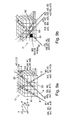
- FIGS. 17A-17N schematically illustrate various detecting units and blocks, which may be incorporated in camera designs, in accordance with embodiments of the present invention.
- FIGS. 18A-18D schematically illustrate possible motions of a radioactive-emission camera, for a single detecting unit and a single block, in accordance with embodiments of the present invention
- FIGS. 19A-19E schematically illustrate other possible motions of a radioactive-emission camera, for a single block, in accordance with embodiments of the present invention.
- FIGS. 20A-20H schematically illustrate possible motions of a radioactive-emission camera, having a plurality of pairs of radioactive-emission blocks
- FIGS. 21A-21D schematically illustrate other possible motions of a radioactive-emission camera, having a plurality of pairs of radioactive-emission blocks
- FIGS. 22A-22X schematically illustrate a radioactive-emission camera system, comprising a plurality of assemblies, motions of individual blocks, and characteristics of an optimal camera, in accordance with embodiments of the present invention
- FIG. 22 Y- 22 AA schematically illustrate a center of viewing, for a given camera design, in accordance with embodiments of the present invention
- FIGS. 23A-23D schematically illustrate a radioactive-emission camera system, in accordance with embodiments of the present invention.
- FIGS. 24A-24C schematically illustrate the modeling of a prostate as a process of two iterations, for zooming in on a pathology, in accordance with embodiments of the present invention
- FIGS. 25A-25E schematically illustrate the external appearance and the internal structure of the radioactive-emission camera for the prostate, in accordance with an embodiment of the present invention
- FIG. 26 illustrates further the internal structure of the radioactive-emission camera for the prostate, in accordance with an embodiment of the present invention
- FIG. 27 schematically illustrates the radioactive-emission camera for the prostate, integrated with an ultrasound camera, in accordance with another embodiment of the present invention
- FIG. 28 schematically illustrates an ultrasound wave impinging on a prostate, in accordance with embodiments of the present invention.
- FIGS. 29A-29C illustrate the co-registering of a radioactive-emission image and an ultrasound image, in accordance with embodiments of the present invention
- FIG. 30 schematically illustrates the radioactive-emission camera for the prostate, integrated with a surgical needle, in accordance with another embodiment of the present invention.
- FIGS. 31 and 32 schematically illustrates the operation of the surgical needle of FIG. 30 ;
- FIG. 33 schematically illustrates the modeling of the female reproductive system as a process of two iterations, for zooming in on a pathology, in accordance with embodiments of the present invention
- FIGS. 34A-34R schematically illustrate the external appearance and the internal structure of the radioactive-emission camera for the female reproduction tract, in accordance with an embodiment of the present invention
- FIGS. 35A-35Q schematically illustrate the external appearance and the internal structure of the radioactive-emission camera for the esophagus, in accordance with an embodiment of the present invention
- FIGS. 36A and 36B schematically illustrates body organs, including an esophagus.
- FIGS. 37-39 schematically illustrate the modeling of the heart as a process of two iterations, in accordance with embodiments of the present invention.
- FIGS. 40-45 schematically illustrate the basic components of a cardiac camera system, in accordance with an embodiment of the present invention.
- FIG. 46 schematically illustrates the external appearance of a radioactive-emission-camera system for the heart, in accordance with an embodiment of the present invention
- FIGS. 47 and 48 schematically illustrate the internal structure of the radioactive-emission camera for the heart, in accordance with an embodiment of the present invention
- FIGS. 49A and 49B schematically illustrate the internal structure of the radioactive-emission camera for the heart, in accordance with an embodiment of the present invention
- FIG. 50 schematically illustrates the construction of radiation detection blocks, in accordance with an embodiment of the present invention.
- FIG. 51 schematically illustrates a cardiac model, in accordance with an embodiment of the present invention.
- FIGS. 52A-52E schematically illustrate radiation detection blocks arranged for viewing a cardiac model, in accordance with an embodiment of the present invention
- FIG. 53 schematically illustrates a dual imaging system for radioactive-emissions in tandem with a three-dimensional structural imager, in accordance with an embodiment of the present invention
- FIG. 54 schematically illustrates a dual imaging system for radioactive-emissions in tandem with a three-dimensional structural imager, in accordance with an embodiment of the present invention
- FIGS. 56A-56B schematically illustrate the internal structure of the radioactive-emission camera for the dual imaging system, in accordance with an embodiment of the present invention
- FIGS. 60A-60K schematically illustrate the internal structure of the radioactive-emission camera for the head, in accordance with an embodiment of the present invention
- FIGS. 61A and 61B schematically illustrate a breast model, in accordance with an embodiment of the present invention
- FIGS. 62A-62C schematically illustrate an imaging system for radioactive-emissions of the breast, in accordance with an embodiment of the present invention
- FIGS. 63A-63E schematically illustrate an imaging camera for radioactive-emissions of the breast, in accordance with an embodiment of the present invention
- FIGS. 64A-64K schematically illustrate an imaging system for radioactive-emissions of the breast, in accordance with an embodiment of the present invention
- FIGS. 64L-64M illustrates, in flowchart form, a method of examining a breast, in accordance with embodiments of the present invention
- FIGS. 65A-65C schematically illustrate an imaging camera for radioactive-emissions of the breast, in accordance with an embodiment of the present invention
- FIGS. 66A-66G schematically illustrate an imaging system for radioactive-emissions of the breast, in accordance with an embodiment of the present invention
- FIGS. 67A-67B schematically illustrate effect of distance on detection efficiency of a radiation detector
- FIGS. 68A-68D schematically illustrate effect of distance on resolution of a radiation detector
- FIGS. 69A-69D schematically illustrate “wasteful viewing” by an array of radiation detectors
- FIGS. 70A-70C describe experimental results with grid point sources.
- FIG. 71 schematically illustrates a non-wasteful radiation detector array, in accordance with an embodiment of the present invention.
- FIGS. 72A-72E schematically illustrate non-wasteful radiation detector arrays, in accordance with an embodiment of the present invention.
- FIGS. 73A and 73B schematically illustrate non-wasteful radiation detector arrays, in accordance with an embodiment of the present invention
- FIGS. 75A and 75B illustrate Teboroxime physiological behavior, according to Garcia et al. (Am. J. Cardiol. 51 st Annual Scientific Session, 2002).
- FIGS. 76A-80D schematically illustrate experimental data with the camera of the present invention.
- FIG. 82 is a simplified flowchart of a method of performing radioactive-emission measurements of a body structure, according to a preferred embodiment of the present invention.
- FIG. 84 a illustrates an object having two high-emission regions of interest.
- FIG. 84 b illustrates the added information provided by each of views V A to V F .
- FIGS. 85 a and 85 b are simplified flowcharts of iterative methods of performing radioactive-emission measurements of a body structure, according to a first and a second preferred embodiment of the present invention.
- FIGS. 86 a and 86 b are simplified flowcharts of methods for dynamically defining further views, according to a first and a second preferred embodiment of the present invention.
- FIG. 87 is a simplified flowchart of an iterative method for selecting further views, according to a preferred embodiment of the present invention.
- FIG. 88 is a simplified flowchart of a single iteration of a view selection method, according to a preferred embodiment of the present invention.
- FIG. 89 is a simplified flowchart of a method for dynamically defining further views, according to a third preferred embodiment of the present invention.
- FIG. 90 is a simplified block diagram of measurement unit for performing radioactive-emission measurements of a body structure, according to a preferred embodiment of the present invention.
- FIG. 93 is a schematic representation of a dynamic model of a voxel, according to a second preferred embodiment of the present invention.
- FIG. 94 is a schematic representation of a dynamic model of a voxel, according to a third preferred embodiment of the present invention.
- FIG. 95 is a circuit diagram of a series RLC electronic circuit.
- FIG. 96 is a simplified flowchart of a method for measuring kinetic parameters of a radiopharmaceutical in an organ of a body, according to a preferred embodiment of the present invention.
- FIG. 98 is a simplified flowchart of a method of radiopharmaceutical administration and imaging, according to a first preferred embodiment of the present invention.
- FIG. 99 is a simplified flowchart of a method of radiopharmaceutical administration and imaging, according to a second preferred embodiment of the present invention.
- FIG. 100 is a simplified block diagram of a radiopharmaceutical management system, according to a preferred embodiment of the present invention.
- FIG. 102 is a block diagram of an exemplary embodiment of an imaging module.
- FIG. 103 is a simplified illustrative diagram of a single-reservoir controllable syringe.
- FIG. 104 is a simplified illustrative diagram of a multiple-reservoir controllable syringe.
- FIG. 105 is a simplified illustrative diagram of an administration device for controlled injection of multiple substances into a patient under the supervision of an imaging module, according to a preferred embodiment of the present invention.
- FIG. 106 is a simplified block diagram of a dose preparation system, according to a preferred embodiment of the present invention.
- FIG. 107 is a simplified flow chart, illustrating a process for imaging a patient using multiple kinetic parameters and measuring the distance between respective kinetic parameters, to relate the patient or individual voxels or groups of voxels to existing groups, thereby to arrive at a decision, regarding the patient or individual voxels or groups of voxels, according to embodiments of the present invention.
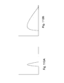
- FIG. 110B illustrates the dynamic behavior of the same parameter with a healthy membrane.
- FIGS. 112A and 112B are of cardiac and respiratory gating in accordance with a first embodiment, in accordance with embodiments of the present invention.
- FIGS. 113A-113C are of cardiac and respiratory gating in accordance with a first embodiment, in accordance with embodiments of the present invention.
- FIGS. 114A , 114 B and 114 C are of typical cardiac volumes and pressures, superimposed against the ECG tracing of FIG. 1B and the time scale 10 of FIG. 3A , in accordance with embodiments of the present invention;
- FIG. 115 is a graph of cardiac volume versus pressure over time and exemplary volumetric images, in accordance with embodiments of the present invention.
- FIG. 116 is of a cardiac probe, in accordance with embodiments of the present invention.
- FIG. 117 is a flowchart diagram of a method for calibrating a radiological imaging system by detecting radiation from one or more calibration sources, according to various exemplary embodiments of the invention.
- FIG. 120 is a schematic illustration of a device for administering radiopharmaceuticals to a subject, according to various exemplary embodiments of the invention.
- FIGS. 121 a - e are schematic illustrations of a system for generating a three-dimensional image of a target region of a subject, according to various exemplary embodiments of the invention.
- FIG. 122 is a flowchart diagram of a method for constructing a three-dimensional image of a target region of a subject, according to various exemplary embodiments of the invention.
- FIG. 123 is a flowchart diagram of a method for constructing a radiological image of a target region of a subject, according to various exemplary embodiments of the invention.
- FIG. 124 is a flowchart diagram of a method for calculating intensity attenuation of a radiological image, according to various exemplary embodiments of the invention.
- FIG. 125 is a schematic diagram of a configuration for acquiring and/or using multi-parametric information, in accordance with an exemplary embodiment of the invention.
- FIG. 126 is a flowchart of a method of acquiring and/or using multi-parametric information, in accordance with an exemplary embodiment of the invention.
- FIG. 127 is a simplified space indicating a diagnosis and a normal physiological state, in accordance with an exemplary embodiment of the invention.
- FIG. 128 shows a simplified two dimensional space showing a complex diagnosis, in accordance with an exemplary embodiment of the invention.
- FIG. 129 is a simplified diagram showing a single detector detecting from a target region
- FIG. 130 is a simplified diagram showing two detector positions (not necessarily simultaneously) allowing three-dimensional information to be obtained from a target region;
- FIGS. 131A-131D show a series of four time absorption characteristics for different radiopharmaceuticals within different tissues
- FIG. 132 is a simplified schematic diagram showing a device for driving an imaging head and allowing control of the imaging head by the image analyzer device;
- FIG. 133 is a simplified flow chart illustrating the image analysis process carried out by the analyzer in FIG. 132 in the case of a single marker;
- FIGS. 134A-134D illustrate two sets of successive images of the same target area taken using two different markers respectively, according to a preferred embodiment of the present invention
- FIG. 135A is a simplified flow chart illustrating a procedure according to a preferred embodiment of the present invention using two or more markers for firstly identifying an organ and secondly determining the presence or otherwise of a pathology within that organ;
- FIG. 135B is a simplified flow chart showing a generalization of FIG. 135A for the general case of two specific patterns
- FIG. 136 is a simplified flow chart illustrating a procedure according to a preferred embodiment of the present invention using two or more markers for identifying a region of low emissivity within a target area and using that identification to control imaging resources to better image the identified region;
- FIGS. 137A-137D illustrate two sets of successive images of the same target area taken using two different markers, in a similar way to that shown in FIG. 134 , except that this time the regions of interest are one inside the other;
- FIG. 138 illustrates differential diagnosis using simultaneous imaging of two different radiopharmaceuticals.
- FIGS. 139A-B is a table illustrating various radiopharmaceutical combinations and their uses in nuclear imaging.
- FIG. 140 is a flowchart for imaging two isotopes that provide inappropriate cross talk, in accordance with embodiments of the present invention.
- FIG. 141 schematically represents a time line for myocardial perfusion, in accordance with embodiments of the present invention.
- FIGS. 142 a - 142 C schematically illustrate photopeaks of Tc 99m , Tl 201 , and cross talk of Tc 99m at the Tl 201 energy window.
- FIG. 143 is a camera electrical diagram showing an electronic block diagram indicating the high limits of the system.
- the monolithic crystal of camera is divided to 40 ⁇ 2 blocks each of which is not affecting the others.
- the conventional camera-every photon paralyzes the camera until cleared.
- FIG. 144 describes a decay curve of Mo-99 to Tc-99m and to Tc-99;
- FIG. 145 describes the build up of Tc-99m and Tc-99 with the decay of Mo-99.
- FIG. 146 describes a standard elution curve
- FIG. 147 describes a recommended low-dose elution curve.
- FIGS. 148A-V are tables describing protocols according to embodiments of the present invention.
- the present invention relates to radioimaging cameras characterized by unprecedented high sensitivity allowing for high resolution image acquisition for use in diagnostics; algorithms and systems operable in conjunction with the camera, the algorithms and systems include, but are not limited to, predetermined view selection algorithm and system, active vision (on the fly view selection) algorithm and system, closed loop administration of a radiopharmaceutical algorithm and system, expert system diagnostic algorithm and system, automatic dose preparation algorithm and kinetic parameter extraction algorithm and system; low dose radiopharmaceuticals; combinations of radiopharmaceuticals either as compositions (cocktails) and/or kits; an administering device of radiopharmaceuticals, which may include syringes, pumps and IV lines; mixers for mixing different radiopharmaceuticals; and an ERP system for controlling and monitoring each one or more of the above.
- the present invention emerges from the development of a radioimaging camera characterized by unprecedented sensitivity.
- the sensitivity of the camera is attributed, as is further detailed hereinbelow, to at least the following constructual features: (a) a plurality of detecting units; (b) movability of the detecting units one with respect to the other; (c) thus allowing concentrated focus on a region-of-interest by the individual detecting units; and (d) wiring diagram with minimal multiplexing, thereby preventing saturation thereof.
- the inventors of the present invention developed low dose preparations of radiopharmaceuticals and compositions and kits comprising two or more radiopharmaceuticals adapted for use in conjunction with the camera and all other aspects of the invention.
- FIGS. 1A and 1B schematically illustrate a detecting unit 12 and a block 90 of detecting units 12 , respectively.
- the detecting unit 12 is formed of a single-pixel detector 91 , having a thickness ⁇ d and a diameter D or, in the case of a non-circular detector, a diameter equivalent. Alternatively, several pixels may be summed up so as to operate, in effect, as a single pixel. Both the detector diameter D and the detector thickness ⁇ d affect the detecting efficiency.
- the detector diameter D determines the surface area on which radioactive emission impinges; the greater the surface area, the greater the efficiency.
- the detector thickness ⁇ d affects the stopping power of the detector. High-energy gamma rays may go through a thin detector; the probability of their detection increases with an increase in the detector thickness ⁇ d .
- FIG. 1A illustrates a single-pixel detector 91 , which by itself cannot generate an image; rather, all counts are distributed over the surface area of the detector 91 .
- the block 90 includes a plurality of the detecting unit 12 , formed by dividing the detector 91 into a plurality of electrically insulated pixels 106 , each associated with a collimator 96 .
- the collimators 96 are of the diameter or diameter equivalent D, a length L, and a septum thickness ⁇ .
- the collimators 96 may be, for example, of lead, tungsten or another material which substantially blocks gamma and beta rays.
- the collimators 96 may be shaped as tubes, rectangular grids, or grids of any other polygon. Wide-angle or narrow-angle collimators are also possible.
- the collimator's geometry and specifically, the ratio of D/L, provides the detecting unit 12 with a collection solid angle ⁇ analogous to the viewing solid angle of an optical camera.
- the collection solid angle ⁇ limits the radioactive-emission detection to substantially only that radioactive emission which impinges on the detector 91 after passing through a “corridor” of the collimator 96 (although in practice, some high-energy gamma rays may penetrate the collimator's walls).
- the collection angle ⁇ is essentially a solid angle of 4 ⁇ steradians.
- the collimator's geometry affects both the detection efficiency and the image resolution, which are defined as follows:
- the detection efficiency is the ratio of measured radiation to emitted radiation.
- the image resolution is the capability of making distinguishable closely adjacent manifestations of a pathology, or the capability to accurately determine the size and shape of individual manifestations of a pathology.
- a wide-aperture, single-pixel detecting unit such as that of FIG. 1A provides high efficiency, it does not lend itself to the generation of a two-dimensional image, and the wide aperture blurs the information regarding the direction from which the radiation is emitted. Yet as the resolution is increased, for example, in the detecting unit 12 of FIG. 1B , the detection efficiency decreases.
- FIG. 2 schematically illustrates the basic component of a system 120 comprising a radioactive-emission camera 122 , operative as a detection system, and a position-tracking device 124 , both in communication with a data-processing system 126 .
- the radioactive-emission camera 122 is associated with a first coordinate system 128
- the position-tracking device 124 is associated with a second coordinate system 128 ′, wherein the position-tracking device 124 monitors the position of the radioactive-emission camera 122 as a function of time.
- the data-processing system 126 processes the measurements of both the radioactive-emission camera 122 and the position-tracking device 124 and combines them to form the image.
- FIG. 3A schematically illustrates a manner of operating the radioactive-emission camera 122 with the position-tracking device 124 of the system 120 .
- the radioactive-emission camera 122 moves about an area of radioactive emission 110 , for example, in the direction of an arrow 118 , so as to measure a radioactive emission distribution 112 , as a function of time, while the position-tracking device 124 monitors the position of the camera 122 .
- the radioactive-emission camera 122 may be a single-pixel detector of high efficiency, which is incapable, by itself, of producing images.
- a data-processing system 126 processes a radioactive-count-rate input 121 together with a position-tracking input 123 , using algorithms 125 , to reconstruct an image 110 ′ of the area of radioactive emission 110 for example, on a display unit 129 .
- FIG. 3B Imaging according to this concept is illustrated in FIG. 3B .
- the area of radioactive emission 110 is located in a two-dimensional coordinate system u; v, and includes two hot points 115 .
- the camera 122 moves from a position P( 1 ), at a time t( 1 ), to a position P( 2 ), at a time t( 2 ), while measuring the radioactive emission distribution 112 of the area of radioactive emission 110 , including the hot points 115 .
- miniBirdTM An example of a suitable position-tracking device 124 for use with system 120 is the miniBirdTM, which is a magnetic tracking and location system commercially available from Ascension Technology Corporation, P.O. Box 527, Burlington, Vermont 05402 USA (http://www.ascension-tech.com/graphic.htm).
- the miniBirdTM measures the real-time position and orientation (in six degrees of freedom) of one or more miniaturized sensors, so as to accurately track the spatial location of cameras, instruments, and other devices.
- the dimensions of the miniBirdTM are 18 mm ⁇ 8 mm ⁇ 8 mm for the Model 800 and 10 mm ⁇ 5 mm ⁇ 5 mm the Model 500.
- optical tracking systems which may be used are NDI-POLARIS of Northern Digital Inc., Ontario, Canada, which provides passive or active systems, a magnetic tracking device of NDI-AURORA, an infrared tracking device of E-PEN system, or an ultrasonic tracking device of E-PEN system.
- the position-tracking device may be an articulated-arm position-tracking device, an accelerometer-based position-tracking device, a potentiometer-based position-tracking device, or a radio-frequency-based position-tracking device.
- FIG. 4A schematically illustrates one embodiment of system 120 , including a hand-held, extracorporeal device 170 , which includes the camera 122 , having a detector 132 and a collimator 134 .
- the system 120 also includes a controller 130 and a position-tracking device 124 , wherein the camera 122 and the position-tracking device 124 are associated with the data-processing system 126 discussed above with reference to FIGS. 2-3B .
- FIG. 4B schematically illustrates another embodiment of system 120 wherein an intracorporeal camera device 180 includes the radioactive-emission camera 122 mounted on a catheter 136 .
- the camera 122 includes the detector 132 , the collimator 134 , and the position-tracking device 124 , wherein the camera 122 and the position tracking device 124 are associated with the data-processing system 126 discussed above with reference to FIGS. 2-3B .
- the camera 122 is configured so as to penetrate a tissue 135 , via a Trocar valve 138 .
- a structural imager 137 such as an ultrasound imager or an MRI camera may further be included.
- a suitable motor 154 may be obtained, for example, from B-K Medical A/S, of Gentofte, D K, and may be adapted to transmit information to the data-processing system 126 , regarding the exact position and orientation of the intracorporeal device 190 .
- the motor 154 may be used in place of the position-tracking device 124 .
- it may be used in addition thereto.
- the intracorporeal device 190 may further include the structural imager 137 , such as an ultrasound imager or an MRI.
- FIGS. 5A-5F present the principles of modeling, for obtaining an optimal set of views, in accordance with embodiments of the present invention.
- FIG. 5A schematically illustrates a body section 230 having a region-of-interest (ROI) 200 .
- the region-of-interest 200 may be associated with a body structure 215 having a specific radioactive-emission-density distribution, possibly suggestive of a pathological feature, this feature termed herein organ target 213 . Additionally, there may be certain physical viewing constraints associated with the region-of-interest 200 .
- FIG. 5C illustrates, in flowchart form, a method 205 for best identifying an optimal and permissible set of views for measuring the radioactive-emissions of the region-of-interest 200 , such that a three-dimensional image thereof may be reconstructed.
- the method 205 includes the following steps:
- the model 250 of the region-of-interest 200 may be based on general medical information of the body structure 215 and common pathological features associated with it. Additionally, the model may be based on information related to a specific patient, such as age, sex, weight, and body type. Furthermore, in order to facilitate generation of the model 250 , a structural image, such as by ultrasound or MRI, may be used for providing information about the size and location of the body structure 215 in relation to the body section 230 .
- a region of concentrated radiation, or a hot region for example, as may be associated with a malignant tumor and as seen in FIG. 5D ;
- a region of low-level radiation which is nonetheless above background level, for example, as may be associated with carcinoma and as seen in FIG. 5E ;
- a view may thus be defined as a group of nonzero probabilities of detecting a radioactive emission associated with all the voxels that form a sector S ( FIG. 6A ).
- a view is sometimes referred to as a projection, and the two terms are synonymous.
- a view defined over a sector S can be naturally extended to be defined over the set of all voxels, by simply associating a zero probability with every voxel outside the sector S. This makes possible the application of mathematical operations over the entire volume U.
- the collection angle ⁇ which, together with the location and orientation parameters P 1 (x 1 ; y 1 ; z 1 ; ⁇ 1 ; ⁇ 1 ; ⁇ 1 ) with respect to the origin P 0 (x 0 ; y 0 ; z 0 ; ⁇ 0 ; ⁇ 0 ; ⁇ 0 ), define the sector S;
- Attenuation properties of all the voxels within the sector S as they affect the probabilities that radioactive emissions from a specific voxel will reach the detector, wherein different voxels within the sector S may have different attenuation properties, since several types of tissue may be involved.
- the tissue attenuation parameters are given. Additionally, the time T 1 since administration of the radiopharmaceutical is generally governed by the blood pool radioactivity, since it is generally necessary to wait until the blood pool radioactivity dies out for low-level detection to be possible. For the remaining viewing parameters, optimization may be carried out.
- the remaining viewing parameters may be divided into two categories:
- FIGS. 7A-7C schematically illustrate anatomical constraints, which may hinder measurements.
- the region-of-interest 200 is associated with the body structure 215 , such as a prostrate, in vivo.
- the radioactive-emission camera 210 may be inserted transrectally, so as to travel in a rectum 206 , for example, in the direction of an arrow 208 . Its ability to image the prostrate is limited by anatomical constraints.
- a box 302 providing a model of the body structure 215 , based on its geometry;
- a scoring function by which any set of at least one view, from a collection of views, is scorable with a score that rates information obtained from the modeled body structure by the set;
- a box 310 forming sets of views from the collection of views and scoring them with the scoring function; and in a box 312 : selecting a set of views, from the collection of views, based on their scores, as the predefined set of views.
- the model of the body structure is based on anatomical knowledge regarding its size, shape, and weight. In fact, different models may be provided, for example, for different ages, sexes, weights, and body types, such as heavy-built, medium-built, or small-built.
- the body structure is modeled assuming that there is no radioactive emission throughout its volume.
- the body structure may be modeled with one or more modeled organ targets, simulating different pathological features.
- the modeled organ targets may be hot regions, of a radioactive-emission intensity higher than the background level, regions of low-level radioactive-emission intensity, which is nonetheless above the background level, and cold regions, of a radioactive-emission intensity lower than the background level. These may be distributed in accordance with medical records, which teach of sites within the body structure that may be more susceptible to certain pathologies.
- model of anatomical constraints which limit accessibility to the body structure is based on anatomical knowledge, and different models may be provided, for example, for different ages, sexes, weights, and body types.
- the collection of views may be obtained by several methods. It may be calculated analytically for the modeled body, based on the view parameters. Additionally or alternatively, computer simulations of the modeled body and the view parameters may provide the collection of views. Additionally or alternatively, measurements may be performed using a point source and a detecting unit of appropriate parameters, at different locations and orientations of the detecting unit, so as to simulate the desired geometries.
- the measurements may be performed in air, but corrected analytically or by computer simulations, for tissue attenuation.
- FIGS. 9A-9F schematically illustrate possible models and collections of views for a body structure, in accordance with embodiments of the present invention.
- FIG. 9A schematically illustrates four views, formed by sectors S 1 , S 2 , S 3 , and S 4 through the volume U, which has an even distribution of radioactive emission.
- FIG. 9B schematically illustrates three views, formed by sectors S 1 , S 2 , and S 3 , through the volume U, which includes a modeled pathological feature, which is the modeled organ target, HS.
- FIG. 9C schematically illustrates three views, formed by sectors S 1 , S 2 , and S 3 through the volume U, which includes a modeled organ target, HS′, of the same type as that of the modeled organ target HS, (that is, either a hot region or a cold region) but somewhat displaced along the x;y;z coordinate system. Additionally, the modeled organ target HS of FIG. 9B is superimposed in FIG. 9C , for illustrative purposes, in order to show the displacement, delta 1 , of modeled organ target HS′ from modeled organ target HS.
- FIG. 9D schematically illustrates three views, formed by sectors S 1 , S 2 , and S 3 through the volume U, which includes a modeled organ target, HS′′, of the same type as that of the modeled organ targets HS and HS′, but somewhat displaced along the x;y;z coordinate system from them. Additionally, the modeled organ targets HS of FIG. 9B and HS′ of FIG. 9C are superimposed in FIG. 9D , for illustrative purposes, in order to show the displacements delta 2 and delta 3 , vis a vis HS′′ of FIG. 9D .
- FIG. 9E schematically illustrates three views, formed by sectors S 1 , S 2 , and S 3 through the volume U, which includes two modeled organ targets, HS 1 and HS 2 .
- FIG. 9F schematically illustrates four possible models of organs, shown as elliptical volumes, each with a slightly different distribution of modeled organ targets.
- any pair of models of organs having different distributions of modeled organ targets may be utilized for identifying an optimal set of views in terms of separability.
- a box 322 providing a model of a body structure, based on its geometry
- a scoring function by which any set of at least one view, from a collection of views is scorable with a score that rates information, obtained from the modeled body structure by the set;
- the region-of-interest 200 associated with the body structure 215 , is defined for the body section 230 .
- a model 250 of a volume U is provided for the second, inner region-of-interest 200 ′, preferably, with at least one modeled organ target HS, simulating the suspected organ target 213 , for obtaining an optimal pathology set of views for the region-of-interest 200 ′.
- the second, pathology set of views is then applied to the body section 230 .
- a box 346 providing a first collection of views of the modeled body structure, obtained within the modeled anatomical constraints;
- a box 348 providing a first scoring function, by which any set of at least one view, from a collection of views, is scorable with a score that rates information, obtained from the modeled body structure by the set;
- a box 350 forming sets of views from the first collection of views, and scoring them, with the first scoring function
- a box 352 selecting a set of views from the first collection of views of the modeled body structure, based on its score, as the predefined set of views;
- a box 358 providing a model of the suspected pathological feature, based on its location in the body structure and general medical knowledge;
- a box 360 providing a model of the anatomical constraints, which limit accessibility to the suspected pathological feature;
- a box 362 providing a second collection of views of the modeled suspected pathological feature, obtained within the modeled pathology's anatomical constraints;
- a box 365 forming sets of views from the second collection of views, and scoring them, with the second scoring function
- a box 366 selecting a set of pathology views from the second collection of views, based on its score, as the predefined pathology set of views;
- a box 368 performing radioactive-emission measurements of the suspected pathological feature, selectively at the predefined pathology set of views.
- FIGS. 5A-12 relate to predefining a set of optimal views for a given radioactive-emission camera and a body structure
- another side of the same coin relates to an optimal design of the radioactive-emission camera and camera system for the body structure, optimized with respect to functional information gained.
- FIGS. 13A-15 illustrate methods of designing cameras and camera systems, optimized with respect to information gained about a body structure.
- FIGS. 13A-13E schematically illustrate possible designs of the radioactive-emission camera 10 , and the process of obtaining views for a given camera design, in accordance with embodiments of the present invention.
- FIGS. 13A-13C schematically illustrate the radioactive-emission camera 10 as a radioactive-emission camera 226 arranged for measuring the radioactive-emission-density distribution of three bodies, U 1 , U 2 and U 3 .
- the volume U 1 of FIG. 13A has been modeled with no modeled organ targets, in order to score the radioactive-emission camera 226 in terms of uniformity.
- the volume U 2 of FIG. 13B includes two modeled organ targets, HS 1 and HS 2 , and may be used for scoring the radioactive-emission camera 226 in terms of reliability.
- the volume U 3 of FIG. 13C includes two modeled organ targets, HS 1 and HS 2 ′, so as to form a pair with the volume U 2 of FIG.
- the pair may be used for scoring the radioactive-emission camera 226 in terms of separability.
- the volume U 3 may be used to obtain a second score in terms of reliability, and the two reliability scores may be averaged.
- additional bodies, of different radioactive emission density distributions may be used, for obtaining additional scores in terms of reliability, and for forming additional pairs, for additional scores in terms of separability, wherein the scores in terms of each scoring function may be averaged.
- the scores of the three functions may be combined, for example, as a sum, or as a weighted average. It will be appreciated that only one of the scoring functions, or only two of the scoring functions may be used. Additionally or alternatively, another scoring function or other scoring functions may be used.
- the camera 226 has two detecting units 222 A and 222 B whose collimators are arranged in parallel.
- the two detecting units 222 A and 222 B are adapted for motion in the directions of ⁇ x, within the camera 226 , as shown by arrows 224 and 228 , so as to provide coverage of a plane within the bodies U 1 U 2 and U 3 , in parallel sectors.
- the two detecting units 222 A and 222 B may be rotated in the direction of ⁇ , as shown by an arrow 217 , and return in the ⁇ x direction of the arrow 228 . In this manner, complete coverage of the whole body is provided.
- a representative collection of views of the camera 226 may be defined as a set of views of the bodies U 1 , U 2 , and U 3 , taken at predetermined increments of ⁇ x and ⁇ .
- a set formed of parallel sectors may score poorly in terms of uniformity since radioactive emissions from voxels closer to the detecting unit have higher probabilities of being detected than radioactive emissions from voxels far from the detecting unit. Additionally, a set formed of parallel sectors may score poorly in terms of separability, since it cannot distinguish between two models, which only differ in the depth of a pathological feature, along the z-axis.
- the camera 220 has the two detecting units 222 A and 222 B, arranged to sweep a plane within the volume U 2 , in a windshield-wiper-like manner, along ⁇ , as illustrated by arrows 216 and 218 .
- the detecting units 222 A and 222 B rotate a few degrees along ⁇ , as illustrated by the arrow 217 , and sweeping along ⁇ is repeated in the new orientation. In this manner, coverage of the whole volume U 2 is performed, from two locations and a large plurality of orientations.
- a representative collection of views of the camera 220 may be defined as a set of views of the volume U 2 , taken at predetermined increments of ⁇ and ⁇ .
- the different detecting units 222 A and 222 B provide views from different orientations
- the different detecting units 222 A and 222 B may change their view orientations.
- a score may be applied to this set, based on the information theoretic measure of reliability.
- the camera 220 may be arranged for measuring the radioactive-emission-density distribution of the volume U 1 ( FIG. 13A ) and of the volume U 3 ( FIG. 13C ), and possibly also of other bodies, in order to score the radioactive-emission camera 220 also in terms of uniformity and separability.
- the scores of the three functions may be combined, for example, as a sum, or as a weighted average. It will be appreciated that only one of the scoring functions, or only two of the scoring functions may be used. Additionally or alternatively, another scoring function or other scoring functions may be used.
- the set of representative collection of views of the present example is likely to score more highly in terms of separability than that of the camera 226 of FIG. 13A , as it provides views from different locations and orientations.
- the detecting units 222 A and 222 B of the camera 220 are further adapted for motion in the directions of ⁇ x, within the camera 220 , as shown by the arrows 224 and 228 .
- the set of representative collection of views of the present example is likely to score more highly in terms of all three information theoretic measures, than those of the camera of FIGS. 13A-13C and of the camera of FIG. 13D , as the present example provides views from a large plurality of locations and orientations.
- the information theoretic measures may be used for scoring representative collections of views of suggested camera designs, and an optimal camera design may be chosen based on this score, as described hereinbelow, with reference to FIG. 14 , hereinbelow.
- FIG. 14 illustrates, in flowchart form, a method 370 for identifying a camera optimized with respect to information gained about the body structure.
- the method 370 comprises:
- a box 372 providing a model of a body structure, based on its geometry
- a box 374 providing a model of anatomical constraints, which limit accessibility to the body structure;
- a scoring function by which each representative collection of views, associated with a specific camera design, is scorable with a score that rates information, obtained from the body structure;
- a box 377 scoring the representative collections of views, with the scoring function; and in a box 378 : selecting a camera design, based on the score of its representative collection of views.
- the rate of data collection is important both because it may be associated with patient discomfort and because it affects the number of patients that may be examined in a period of time. Where data collection with one camera design may take an hour and with another camera design may take 10 minutes, the design of the faster camera is highly advantageous. Complexity and cost are important because they affect the accessibility of the camera to the general public.
- a design scoring function may be provided, for rating each camera design with a design score, based on any one or a combination of the secondary issues.
- the design scoring function may be used for selecting a camera design from several that have been found acceptable in terms of the quality of the data, by the method 370 of FIG. 14 .
- FIG. 15 illustrates, in flowchart form, a method 380 of selecting a camera design, optimized with respect to information gained about a body structure and secondary issues, in accordance with embodiments of the present invention.
- the method 380 comprises:
- a box 382 providing a model of a body structure, based on its geometry
- a box 384 providing a model of anatomical constraints, which limit accessibility to the body structure;
- a box 385 providing representative collections of views of the modeled body structure, within the modeled anatomical constraints, for different camera designs;
- a scoring function by which each representative collection of views, associated with a specific camera design, is scorable with a score that rates information, obtained from the body structure;
- scoring the representative collections of views, with the scoring function
- a box 390 providing a design scoring function, by which each camera design is scorable, based on the secondary issues;
- a box 394 selecting a camera design, based on its design score.
- FIGS. 16A-16L schematically illustrate viewing the elliptical model 250 of the volume U, with the camera 10 , as illustrated specifically in FIGS. 20A-20H , hereinbelow.
- FIGS. 16A-16K show the spanning of the elliptical model 250 of the volume U, along an x-z plane, by the sweeping views.
- FIG. 16L is a pictorial representation of the camera 10 of FIGS. 20A-20H and the elliptical model 250 of the volume U, in accordance with embodiments of the present invention.
- FIGS. 16A-16K may be used both for:
- the detecting units, blocks and/or assemblies are moved to a position and collect photon emission data while stationary (herein referred to as the Stop-Go imaging scheme).
- a motion of each detecting unit or block or assembly is at a predetermined angle per move (after each move data is collected while the detecting unit or block or assembly is stationary) and characterized by half the angle phase shift when scanning in opposite directions, so as to scan the scanned region every half angle (herein referred to as the Interlacing imaging scheme).
- a motion of each detecting unit or block or assembly is without pause between minimum and maximum sweeping angles (herein referred to as the Sweeping Imaging Scheme).
- a prescan according to embodiments of the present invention can be performed by any imaging device, including, but not limited to, ultrasound and MRI or by a physical inspection of the subject undergoing diagnosis.
- a prescan can be performed by the camera of the present invention preferably using the interlacing imaging scheme as is further described above or by broad view selection as is further described below.
- FIGS. 18A and 18B schematically illustrate the radioactive-emission camera 10 , of the single detecting unit 12 (see FIGS. 1A and 17A ).
- the single detecting unit 12 has a motion with respect to the overall structure 20 , which is a combination of a rotational motion around the x-axis, in the direction of ⁇ , denoted by an arrow 44 , and a translational motion along the x-axis, denoted by an arrow 46 .
- a spiral trace 48 is formed, for example, on an inner surface of a body lumen 232 , as seen in FIG. 18B .
- the motions of the detecting unit 12 are contained within the overall structure 20 , so that the external surface of the camera 10 remains stationary.
- the external surface of the camera may be formed of a carbon fiber, a plastic, or another material, which is substantially transparent to nuclear radiation.
- FIGS. 18C and 18D schematically illustrate the radioactive-emission camera 10 , of the single block 90 ( FIGS. 1B and 17E ).
- the single block 90 has a motion with respect to the overall structure 20 , which is a combination of the rotational motion around the x-axis, in the direction of ⁇ , denoted by the arrow 44 , and the translational motion along the x-axis, denoted by the arrow 46 .
- a plurality of spiral traces 49 is formed, for example, on an inner surface of a body lumen, as seen in FIG. 18D .
- the motions of the block 90 are contained within the overall structure 20 , so that the external surface of the camera 10 remains stationary, wherein the external surface of the camera is substantially transparent to nuclear radiation.
- FIGS. 19A-19E schematically illustrate the radioactive-emission camera 10 , of the single block 90 of a plurality of the detecting units 12 .
- the single block 90 has a motion with respect to the overall structure 20 , which is performed in steps, as follows:
- the motions of the block 90 are contained within the overall structure 20 , so that the external surface of the camera 10 remains stationary, wherein the external surface of the camera is substantially transparent to nuclear radiation.
- FIGS. 20A-20H schematically illustrate the radioactive-emission camera 10 , having at least one pair, or a plurality of pairs of blocks 90 , adapted for the windshield-wiper like oscillatory motion, around the radius r, as denoted by the arrows 50 .
- the oscillatory motions may be synchronized in an antipodal manner, so as to be diametrically opposed to each other, as shown in FIGS. 20B and 20E , by the arrows 54 , and as shown in FIGS. 20C and 21F by the arrows 56 .
- the oscillatory motions need not be synchronized in an antipodal manner. Rather, all the blocks 90 may move in synchronized motion, or each block 90 may move independently. It will be appreciated that an odd number of blocks 90 is also possible.
- a rotational motion of the overall structure 20 , around the x-axis in the direction of ⁇ , an amount ⁇ , to a new measuring position along ⁇ , is provided, after each step of the oscillatory motion, as shown in FIG. 20D , by an arrow 52 .
- the resultant traces are the plurality of broken line traces 59 , as seen in FIG. 20G .
- FIGS. 20A-20F and 20 H provides views which are essentially the same as those of FIGS. 19A-19E , but in a more efficient way, since a plurality of blocks is involved.
- the different blocks 90 provide views from different orientations.
- the different blocks 90 may change their view orientations.
- the motions of the blocks 90 are contained within the overall structure 20 , so that the external surface of the camera 10 remains stationary, wherein the external surface of the camera is substantially transparent to nuclear radiation.
- an internal structure 21 may contain all the blocks 90 , configured to move together, as a rigid structure, while the overall structure 20 and the external surface of the camera 10 remain stationary.
- FIGS. 20A-20H The operational manner of the camera 10 of FIGS. 20A-20H is described with reference to FIG. 23C , hereinbelow.
- FIGS. 21A-21D schematically illustrate the radioactive-emission camera 10 , having at least one pair, or a plurality of pairs of blocks 90 , adapted for the windshield-wiper like oscillatory motion, around the radius r, as denoted by the arrow 50 .
- the oscillatory motions are preferably synchronized in an antipodal manner, so as to be diametrically opposed to each other, as in, for example, FIG. 20B . It will be appreciated that the oscillatory motions need not be synchronized in an antipodal manner. Rather, all the blocks 90 may move in synchronized motion, or each block 90 may move independently. It will be appreciated that an odd number of blocks 90 is also possible.
- the resultant traces are the plurality of broken line traces 59 , as seen in FIG. 21D .
- the camera 10 of FIGS. 21A-21C provides views which are essentially the same as those of FIG. 19E , and of FIG. 20G , but in a different manner.
- the different blocks 90 provide views from different orientations.
- the motions of the blocks 90 are contained within the overall structure 20 , so that the external surface of the camera 10 remains stationary, wherein the external surface of the camera is substantially transparent to nuclear radiation.
- the detecting units 12 may be used in place of the blocks 90 .
- FIGS. 22A-22C and 22 E- 22 G schematically illustrate the radioactive-emission camera 95 , comprising the plurality of assemblies 92 , each assembly 92 being similar in construction to the structure 21 of FIG. 20H , in accordance with embodiments of the present invention.
- the plurality of assemblies 92 are preferably arranged in parallel, and their rotational motions, around the x-axis, may be synchronized in an antipodal manner, so as to be diametrically opposed to each other, as shown in FIG. 22C , by arrows 62 , and in FIG. 22G , by arrows 64 . It will be appreciated that the rotational motion around the x-axis need not be synchronized in an antipodal manner, and may be performed in parallel, or independently.
- the resultant traces are a large plurality of the broken line traces 66 and 68 , as seen in FIGS. 22D and 22H .
- the camera 95 provides views which are essentially the same as those of FIGS. 19E , 20 G, and 21 D, but far more efficiently, since a plurality of assemblies is involved.
- the different blocks 90 may change their view orientations
- the different assemblies 92 provide views from different orientations.
- the different assemblies 92 may change their view orientations.
- the motions of the blocks 90 and of the assemblies 92 are contained within the overall structure 20 , so that the external surface of the camera 95 remains stationary, wherein the external surface of the camera 95 is substantially transparent to nuclear radiation.
- camera 95 may include a plurality of assemblies 92 , which are not parallel to each other.
- the assemblies 92 may be at right angles to each other, or at some other angle.
- assemblies 92 may include the detecting units 12 rather then the blocks 90 .
- FIGS. 22I-22X schematically illustrate possible individual motions for blocks 90 , in accordance with embodiments of the present invention.
- each of the blocks 90 may be in communication with two motion providers, for providing the oscillatory motion about the r-axis, as seen by the arrows 50 , and for providing the rotational motion around the x-axis, as seen by the arrows 44 .
- a first set of measurements is performed as the blocks 90 oscillate about the r-axis, as seen in FIG. 22J .
- the resultant traces are a large plurality of the broken line traces 66 and 68 , as seen in FIGS. 22J and 22M , and are substantially the same as those of FIGS. 22D and 22H .
- each of the blocks 90 may be in communication with two motion providers, for providing an oscillatory motion about the x-axis as seen by an arrow 61 , and a rotational motion around the x-axis, as seen by an arrows 63 .
- the resultant trace is star shaped, as seen by the lines 65 of FIG. 220 .
- a tertiary motion provider may be included, for providing a cluster 67 of overlapping lines, for a substantially complete coverage of a region, for example, as seen in FIG. 22P by a cluster 67 of the overlapping star-shaped lines 65 .
- motion providers may include one, two, three or more motion providers.
- the center of viewing 200 A may be a region of uniform viewing, rather than a mere point.
- the region 201 may be a region of uniform viewing, which forms the center of viewing 200 A.
- the computer may be any one of a personal computer, a laptop, a palmtop, or another computer, adapted for communication with the camera, or a microcomputer, built into the camera. Additionally, a combination of a microcomputer, built into the camera, and an external computer such as a personal computer, a laptop, a palmtop, or the like, may be used.
- the personal details are fed into the computer, and the models of the body structure and anatomical constraints are adapted to these details.
- the personal details may include age, sex, weight, body type, and the like.
- a position-tracking device 418 is associated with the camera 10 as a whole, for registering its position with respect to, for example, the body structure 215 ( FIG. 5A ).
- a power supply 410 powers the camera 10 .
- power may be supplied from the grid.
- the transceiver 402 may be adapted to receive input data from an ultrasound imager, for providing information such as location, size of the body structure and the like, by ultrasound imaging, in order to adjust the model of the body structure, hence the locations and orientations of the predefined, optimal set of views, to the particular patient.
- the motion of the one or several motion providers 76 may relate to motion of the overall structure 20 or 220 as a whole, for example, as taught with reference to FIG. 13E , by the motion the camera 220 , as shown by the arrows 224 and 228 .
- the camera 10 includes the blocks 90 , each comprising a plurality of the detecting units 12 , each block 90 moving as a single body.
- a tertiary motion provider may also be used and that many arrangements for providing the motions are possible, and known.
- At least two assemblies 92 may be provided, each with a dedicated motion provider 76 and a dedicated secondary motion provider 78 . It will be appreciated that the multiple motions may be provided to the detecting units 12 , rather then to the blocks 90 . It will be appreciated that tertiary motion providers may also be used and that many arrangements for providing the motions are possible, and known.
- FIGS. 24A-32 schematically illustrate the radioactive-emission camera 10 , for the prostate, in accordance with an embodiment of the present invention.
- FIGS. 24A-24C schematically illustrate the modeling of a prostate and a location of pathology, as a process of two iterations, for zooming in on the pathology, in accordance with embodiments of the present invention.
- FIG. 24A schematically illustrates a body section 230 , which includes a prostate 260 , which has sections 262 , 264 and 266 , and a pathology 265 in section 264 . Additionally, the body section 230 includes a rectum 268 , from which the prostate 260 may be viewed.
- FIG. 24B schematically illustrates the model 200 of the body section 230 , including the prostate 260 , of sections 262 , 264 and 266 , and the rectum 268 .
- An optimal set of views is predefined based on the model 200 and a first scoring function.
- the first scoring function may be based on regions of interest similar to the pathology 265 , as known, from medical records of common pathologies. Measurements of radioactive emission are then taken at the predefined views, in vivo, for the prostate 260 .
- a second model 250 of the section 264 is made, for zooming in on the pathology 265 , and a second optimal set of views is predefined, based on the second model 250 of the section 264 and a second scoring function, for zooming in on the pathology 265 .
- Measurements of radioactive emission are then taken at the predefined second set of views, in vivo, for the section 264 and the pathology 265 .
- first and second scoring functions may be based on any one of or a combination of the information theoretic measures of uniformity, separability, and reliability. It will be further appreciated that the first and second scoring functions need not be the same.
- the secondary motor 86 may also be an electric motor, for example, a servo motor.
- the secondary motor 86 , secondary shaft 84 and the motion transfer link 74 together, form the secondary motion provider 78 , in the direction of the arrows 224 and 228 of FIG. 13E .
- the different assemblies 90 provide views from different orientations.
- the different assemblies 90 may change their view orientations independent of each other.
- the external surface of the intracorporeal portion 82 ( FIG. 25A ) remains stationary, while the internal structure 21 ( FIG. 25C ) rotates around the x-axis.
- the external surface of the intracorporeal portion 82 may be formed of a carbon fiber, a plastic, or another material, which is substantially transparent to nuclear radiation.
- FIG. 25E illustrates further the internal structure of the radioactive-emission camera for the prostate, in accordance with an embodiment of the present invention, showing the assemblies 90 within the overall structure 20 .
- Each assembly may be a single detecting unit 12 , or a plurality of the detecting units 12 , for example, 36 of the detecting units 12 , for example, as an array of 6 ⁇ 6, or 99 of the detecting units 12 , for example, as an array of 11 ⁇ 9, or another number of the detecting units 12 , arranged as an array or arranged in another geometry.
- FIG. 26 illustrates further the internal structure of the radioactive-emission camera for the prostate, in accordance with an embodiment of the present invention, showing the oscillatory motion (in the direction of the arrows 50 of FIGS. 20A , and 20 C) of the assemblies 90 within the overall structure 20 .
- FIGS. 27-28 schematically illustrate the radioactive-emission camera 10 , for the prostate, in accordance with another embodiment of the present invention.
- the camera 10 further includes an ultrasound transducer 85 , arranged, for example, at the tip of the intracorporeal portion 82 .
- FIG. 27 illustrates the external appearance of the camera 10 with the ultrasound transducer 85 at its tip.
- FIG. 28 illustrates the ultrasound wave 87 , impinging on the prostate 260 .
- FIGS. 29A-29C illustrate the co-registering of a radioactive-emission image and an ultrasound image, to illustrate the functional information of the radioactive-emission image with the structural information of the ultrasound image.
- the ultrasound image is seen in FIG. 29A
- the radioactive-emission image is seen in FIG. 29B
- the co-registering of the two is seen in FIG. 29C .
- FIG. 30 schematically illustrates the radioactive-emission camera 10 , for the prostate, in accordance with another embodiment of the present invention.
- the camera 10 further includes an ultrasound transducer 85 , and a surgical needle 83 , in a needle guide 81 , arranged alongside the camera 10 , for obtaining a biopsy or for other minimally invasive procedures.
- FIG. 30 schematically illustrates the surgical needle 83 as it penetrates the prostate 260 from the rectum 268 .
- FIGS. 31 and 32 schematically illustrate the manner of guiding the needle 83 .
- a track 89 shows the surgeon the direction of the needle, while the camera 10 produces the functional image of the pathology 265 in the prostate 260 .
- the surgeon can align the track 89 with the pathology 265 , as shown in FIG. 32 .
- the needle 83 Once aligned, he can insert the needle 83 , as shown in FIG. 30 .
- the method 340 may be described, pictorially, as follows:
- the model 250 of the volume U is provided for the region-of-interest 200 , possibly with one or several of the modeled organ targets HS, and within the anatomical constraints AC, for obtaining the optimal set of views for the region-of-interest 200 .
- the optimal set of views is then applied to the body section 230 .
- the intracorporeal portion 630 defines a cylindrical coordinate system of x;r, wherein x is the longitudinal axis.
- the plurality of blocks 90 along the length of the intracorporeal portion 630 is housed in an internal structure 21 ( FIG. 20H ).
- Each of the blocks 90 is adapted for the windshield-wiper like oscillatory motion, around the radius r, as denoted by the arrows 50 .
- the oscillatory motions may be synchronized in an antipodal manner, so as to be diametrically opposed to each other, as shown hereinabove in FIGS. 20B and 20E , by the arrows 54 , and as shown hereinabove in FIGS. 20C and 20F by the arrows 56 .
- the blocks 90 may move together, or independently. It will be appreciated that an odd number of blocks 90 is also possible.
- the intracorporeal portion 630 may further include dedicated electronics 634 and motion providers 636 , such as miniature motors and motion transfer systems, as known.
- FIGS. 34B and 34C schematically illustrate side and distal views, respectively, of the radioactive-emission measuring camera 600 , having an ultrasound imager 640 at its distal tip 633 .
- the ultrasound imager 640 may provide a structural image which may be correlated with the functional image. Additionally, it may be used for providing the size and location of the body structure for modeling. Furthermore, it may be used for providing attenuation correction to the radioactive emission measurements.
- FIGS. 34F-34I schematically illustrate the radioactive-emission measuring camera 600 , having a distal block 90 A at its distal tip 633 .
- the distal block 90 A at the distal tip is also adapted for oscillatory motion, but about the x-axis, as seen by an arrow 53 .
- traces 55 When combined with the rotational motion around the x-axis, it produces traces 55 in the shape of a star, in the body section 230 , as seen in FIG. 34K .
- FIGS. 34L-34Q schematically illustrates the radioactive-emission measuring camera 600 , for a body lumen, having the distal block 90 A at its distal tip 633 , adapted for a deployed and a retracted position, and for oscillatory motion about the x-axis, when deployed.
- the camera 600 further has the ultrasound imager 640 at its distal tip 633 , as a ring, similarly having a deployed and a retracted position.
- FIG. 34Q illustrates the distal block 90 A retracted and the ultrasound imager deployed so the distal block 90 A does not obstruct the view of the ultrasound imager. It will be appreciated that the ultrasound image is to be taken once, from the distal tip 633 , while the radioactive-emission measurements are to be taken at a plurality of orientations, from the distal tip 633 .
- FIGS. 35A-35Q schematically illustrate radioactive-emission measuring cameras 600 , adapted for the esophagus, in accordance with preferred embodiments of the present invention.
- FIG. 35A schematically illustrates the basic radioactive-emission measuring camera 600 , for the esophagus.
- the camera 600 includes an extracorporeal portion 610 , which comprises a control unit, and an intracorporeal portion 630 , having proximal and distal ends 631 and 633 , with respect to an operator (not shown).
- a flexible cable 620 connects between them.
- the control unit 610 may include control buttons 612 and possibly a display screen 614 , and may provide connections with a computer station. It may receive power from a grid or be battery operated.
- the control unit 610 may further include a computer or a microcomputer.
- the intracorporeal portion 630 is constructed essentially as the camera 10 of FIG. 23C and FIGS. 20A-20H , and specifically, FIG. 20H .
- the intracorporeal section 630 defines a cylindrical coordinate system of x;r, wherein x is the longitudinal axis.
- the plurality of blocks 90 along the intracorporeal portion 630 is housed in an internal structure 21 .
- Each of the blocks 90 is adapted for the windshield-wiper like oscillatory motion, around the radius r, as denoted by the arrows 50 .
- the oscillatory motions may be synchronized in an antipodal manner, so as to be diametrically opposed to each other, as shown hereinabove in FIGS. 20B and 20E , by the arrows 54 , and as shown hereinabove in FIGS. 20C and 20F by the arrows 56 .
- the blocks 90 may move together, or independently. It will be appreciated that an odd number of blocks 90 is also possible.
- the internal structure 21 is adapted for rotational motion around the x-axis, in the direction of ⁇ , wherein after each step of oscillatory motion at a certain orientation of c, the internal structure 21 rotates by a step to a new orientation of (o, and the oscillatory motion is repeated.
- the controller or the computer registers the locations and orientations of each detecting unit or block and correlates the measurements with the corresponding positions and orientations.
- a position-tracking device 635 may also be used, for providing information regarding the position of the camera relative to a known reference.
- the camera 600 may include detecting units 12 rather then blocks 90 .
- the overall structure 20 remains stationary, and has an external surface, which is substantially transparent to nuclear radiation.
- a ball bearing 632 may be used at the connecting point with the cable 620 , to enable the rotational motion.
- the intracorporeal section 630 may further include dedicated electronics 634 and motion providers 636 , such as miniature motors and motion transfer systems, as known. Alternatively, the motion may be transferred via the cable 620 .
- FIGS. 35B and 35C schematically illustrate side and distal views, respectively, of the radioactive-emission measuring camera 600 , for the esophagus, having an ultrasound imager 640 at its distal tip 633 .
- the ultrasound imager 640 may provide a structural image which may be correlated with the functional image. Additionally, it may be used for providing the size and location of the relevant organ for modeling. Furthermore, it may be used for providing attenuation correction to the radioactive emission measurements.
- FIGS. 35D and 35E schematically illustrate side and distal views, respectively, of the radioactive-emission measuring camera 600 , for the esophagus, having an MRI imager 642 at its distal tip 633 .
- the MRI imager 642 may provide a structural image which may be correlated with the functional image. Additionally, it may be used for providing the size and location of the relevant organ for modeling. Furthermore, it may be used for providing attenuation correction to the radioactive emission measurements.
- FIGS. 35F-35I schematically illustrate the radioactive-emission measuring camera 600 , for the esophagus, having a block 90 at its distal tip 633 .
- the block 90 at the distal tip is also adapted for oscillatory motion, but about the x-axis, as seen by an arrow 53 .
- traces 55 When combined with the rotational motion around the x-axis, it produces traces 55 in the shape of a star, in the body section 230 , as seen in FIG. 35K .
- FIGS. 35L-35Q schematically illustrates the radioactive-emission measuring camera 600 , for the esophagus, having a block 90 at its distal tip 633 , adapted for a deployed and a retracted position, and for oscillatory motion about the x-axis, when deployed.
- the camera 600 further has the ultrasound imager 640 at its distal tip 633 , as a ring, similarly having a deployed and a retracted position.
- FIGS. 35N-35P illustrate the block 90 deployed, and the ultrasound imager 640 retracted. In this manner, the ultrasound imager 640 does not obstruct the oscillatory motion of the block 90 at the distal tip 633 .
- FIG. 35Q illustrates the block 90 retracted and the ultrasound imager deployed so the block 90 does not obstruct the view of the ultrasound imager. It will be appreciated that the ultrasound image is to be taken once, from the distal tip 633 , while the radioactive-emission measurements are to be taken at a plurality of orientations, from the distal tip 633 .
- FIGS. 36A and 36B schematically illustrates the body section 230 , showing an esophagus 650 .
- the radioactive-emission measuring camera 600 for the esophagus ( FIGS. 35A-35Q ), is adapted for oral insertion, through a mouth 652 , and is further designed for identifying pathological features in a neck area 654 , for example, as relating to the vocal cords, the thyroid gland, the submandibular glands.
- the trachea 656 is designed for identifying pathological features in the trachea 656 , the lungs 658 , the heart 660 , the breasts, the stomach 662 , the pancreas 664 , and the liver 666 , as well as other relevant organs and glands, for example, the lymph glands.
- the camera system of the present invention allows imaging of internal organs from a close proximity. Additionally, it is particularly advantageous for overweight people and for women with large breasts, for whom extracorporeal imaging, for example, extracorporeal cardiac imaging by nuclear emission measurements, is ineffective, because of losses in the tissue.
- the radiopharmaceuticals associated with the camera of FIGS. 35A-35Q may be MyoviewTM (technetium Tc-99m tetrofosmin), a cardiac imaging agent, of GE Healthcare, GE Medical Systems, http://www.gehealthcare.com/contact/contact_details.html#diothers.
- other agents may be used, as known, for other relevant organs, for example, for the detection of cancerous tissue or other pathologies.
- cardiac imaging is performed with Teboroxime, for example, for myocardial perfusion imaging.
- radioactive-emission measuring camera 600 for the esophagus of the present invention may also be used in parallel with the cardiac camera system 500 of Example 12, described hereinbelow.
- FIGS. 37-39 schematically illustrate the body section 230 , as a heart, which includes the region-of-interest 200 , associated with the organ 215 , being the heart, which includes an aorta 242 , a left atrium 244 and a right atrium 246 .
- FIG. 38 schematically illustrates a second, inner region-of-interest 200 ′, associated with the aorta 242 .
- FIG. 39 schematically illustrates a second, inner region-of-interest 200 ′, associated with the left atrium 244 .
- FIGS. 40-52E schematically illustrate a cardiac camera system 500 , in accordance with a preferred embodiment of the present invention.
- FIGS. 40-45 schematically illustrate the basic components of the cardiac camera system 500 , in accordance with embodiments of the present invention. These include an operator computer station 510 , a chair 520 , and a radioactive-emission camera assembly 530 .
- FIG. 44 schematically illustrate a camera 530 A, which includes shoulder sections 530 B, for viewing the heart essentially from a base of the cylindrical volume, in accordance with embodiments of the present invention.
- FIG. 45 schematically illustrate cameras 530 B, formed as shoulder sections for viewing the heart essentially from a base of the cylindrical volume, in accordance with an alternative embodiment of the present invention.
- FIG. 44 or 45 Views from the shoulders, either as in FIG. 44 or 45 provides information not blocked or hidden by the chest.
- FIGS. 47-48 schematically illustrate possible inner structures of the camera assembly, in accordance with preferred embodiments of the present invention.
- the camera assembly 530 defines an internal frame of reference 80 , while each assembly 92 has a reference cylindrical coordinate system of x;r, with rotation around x denoted by ⁇ and rotation around r denoted by ⁇ , wherein the oscillatory motion about r
- the motion of the camera assembly 530 corresponds to that described hereinabove, with reference to FIGS. 20A-20H and 22 A- 22 H, as follows:
- the plurality of blocks 90 is adapted for the windshield-wiper like oscillatory motion, around the radius r, as denoted by the arrow 50 .
- the oscillatory motions may be synchronized in an antipodal manner, so as to be diametrically opposed to each other, as shown hereinabove in FIGS. 20B and 20E , by the arrows 54 , and as shown hereinabove in FIGS. 20C and 20F by the arrows 56 .
- the blocks 90 may move together, or independently. It will be appreciated that an odd number of blocks 90 is also possible.
- the plurality of assemblies 92 are preferably arranged in parallel, and their rotational motions, around the x-axis, in the direction of c, may also be synchronized in an antipodal manner, so as to be diametrically opposed to each other, as shown hereinabove, in FIG. 22C , by arrows 62 , and as shown hereinabove in FIG. 22 G, by arrows 64 .
- other motions are also possible.
- the assemblies 92 may move together, or independently. It will be appreciated that an odd number of assemblies 92 is also possible.
- the resultant traces are a large plurality of the broken line traces 59 , as seen hereinabove, with reference to FIGS. 22D and 22H , on the chest of the patient.
- the different blocks 90 provide views from different orientations
- the different blocks 90 may change their view orientations
- the different assemblies 92 provide views from different orientations; and iv.
- the different assemblies 92 may change their view orientations.
- the operational manner of the camera 530 is described hereinbelow with reference to FIG. 23D , for the at least two assemblies 92 .
- the motions of the blocks 90 and of the assemblies 92 are contained within the overall structure 20 , so that the external surface of the camera assembly 530 remains stationary, wherein the external surface of the camera assembly 530 is substantially transparent to nuclear radiation.
- the overall structure may be a skeleton, open on the side facing the patient.
- the oscillatory motions need not be synchronized in an antipodal manner. Rather, the blocks 90 may move together, or independently. It will be appreciated that an odd number of blocks 90 is also possible.
- camera 530 may include a plurality of assemblies 92 , which are not parallel to each other.
- the assemblies 92 may be at right angles to each other, or at some other angle.
- the assemblies 92 may include detecting units 12 rather then blocks 90 , for example, as in the camera 10 of FIGS. 20A-20G .
- FIG. 48 schematically illustrates a section 531 of the camera assembly 530 , showing the inner structure thereof, in accordance with another embodiment of the present invention.
- the camera assembly 530 may include the overall structure 20 , and a single one of the assemblies 92 , within the overall structure 20 , having the dedicated motion provider 76 , the dedicated secondary motion provider 78 , and the rows of blocks 90 .
- the camera assembly 530 includes a tertiary motion provider 77 , for sliding the assembly 90 laterally, in the directions of the arrow 75 , along the chest of the patient (not shown). In this manner, imaging of the chest may be performed with the single assembly 92 .
- FIGS. 49A and 49B schematically illustrate the assembly 92 and the block 90 , in accordance with a preferred embodiment of the present invention.
- the assembly 92 is constructed in a manner similar to the camera 10 of FIGS. 20A-20H , and specifically FIG. 20H , and according to FIG. 23D , hereinabove.
- the assembly 92 includes a row of at least two blocks 90 , each adapted for oscillatory motion about r.
- the blocks 90 are arranged within the internal structure 21 .
- a motor 88 and a shaft 85 form the motion provider 76
- a secondary motor 86 and a secondary shaft 84 form the secondary motion provider 78 , for the oscillatory motion about r.
- a plurality of motion transfer systems 74 for example gear systems, equal in number to the number of blocks 90 , transfer the motion of the secondary motion provider 78 to the blocks 90 .
- the motion transfer systems 74 for example, of gears, make it possible to provide the row of blocks 90 with any one of parallel oscillatory motion, antipodal oscillatory motion, or independent motion, depending on the gear systems associated with each block 90 . It will be appreciated that other motion transfer systems, as known, may be used.
- detecting units 12 may be used in place of blocks 90 .
- adjacent blocks 90 A and 90 B may move in an antipodal manner and adjacent blocks 90 C and 90 D may move in an antipodal manner, while adjacent blocks 90 B and 90 C may move in parallel. It will be appreciated that many other arrangements are similarly possible. For example, all the pairing combinations of the blocks 90 may move in an antipodal manner, all the blocks 90 may move in parallel, or the blocks 90 may move independently. It will be appreciated that an odd number of blocks 90 may be used in the assembly 92 .
- FIG. 50 schematically illustrates the block 90 , in accordance with a preferred embodiment of the present invention.
- the block 90 includes a frame 93 , which houses the detector material 91 , which is preferably pixelated, and the collimators 96 . Additionally, the frame 93 houses dedicated electronics 97 , preferably on a PCB board 99 . Furthermore, where several modules of the detector material 91 need to be used, a structural element 89 may be provided to hold the different modules of the detector material 91 together. It will be appreciated that a single pixel detector may be used. Alternatively, a single module of a pixelated detector may be used. Alternatively, the block 90 may be constructed as any of the examples taught with reference to FIGS. 17A-17N , or as another block, as known.
- the dimensions, which are provided in FIG. 50 are in mm. It will be appreciated that other dimensions, which may be larger or smaller, may similarly be used.
- FIG. 51 schematically illustrates the cardiac model 250 , in accordance with a preferred embodiment of the present invention.
- the cardiac model 250 includes the volume U, for example, as a cylinder, and the anatomical constraints AC.
- the rows of blocks 90 are arranged around the volume U, as permissible by the anatomical constraints AC.
- FIGS. 52A-52E schematically illustrate the blocks 90 , arranged for viewing the cardiac model 250 , in accordance with a preferred embodiment of the present invention.
- the block 90 is shown with the frame 93 , which houses the detector material 91 , which is preferably pixelated, and the collimators 96 . Additionally, the frame 93 houses the dedicated electronics 97 , on the PCB board 99 .
- FIG. 52B fields of view 98 of the blocks 90 are seen for a situation wherein adjacent blocks 90 A and 90 B move in an antipodal manner, while adjacent blocks 90 B and 90 C move in a nearly parallel manner.
- the figure illustrates that when moving in an antipodal manner, the blocks 90 do not obstruct each other's field of view 98 . Yet, when moving in a parallel manner, or a near parallel manner, obstruction may occur.
- FIG. 52C A similar observation is made by FIG. 52C , wherein the adjacent blocks 90 B and 90 C move in an antipodal manner, while the adjacent blocks 90 A and 90 B move in a near parallel manner.
- all the pairing combinations of the blocks 90 may move in an antipodal manner, all the blocks 90 may move in parallel, or the blocks 90 may move independently. It will be appreciated that an odd number of blocks 90 may be used in the assembly 92 .
- FIG. 52D illustrates possible dimensions for the cardiac model 250 .
- the dimensions are in mm. It will be appreciated that other dimensions are similarly possible.
- the model 250 may be based on general medical information of the organ 215 and common pathological features associated with it. Additionally, the model may be based on information related to a specific patient, such as age, sex, weight, and body type.
- a structural image such as by ultrasound or MRI, may be used for providing information about the size and location of the heart 215 in relation to the body section 230 ( FIG. 5A ), for generating the model 250 .
- FIG. 52E schematically illustrates a possible arrangement of the blocks 90 for viewing the volume U of the model 250 , within the anatomical constrains AC.
- the significance of the present invention, as illustrated by Figures and 52 E is that all the blocks maintain a close proximity to the modeled volume U, and to the region-of-interest, in vivo, even as they move. This is in sharp contrast to the prior art, for example, as taught by U.S. Pat. No. 6,597,940, to Bishop, et al, and U.S. Pat. No. 6,671,541, to Bishop, in which the blocks are fixed within a rigid overall structure, so that as some of the blocks are placed in close proximity to the body, others are forced away from the body, and their counting efficiency deteriorates.
- the radiopharmaceuticals associated with the camera of FIGS. 40-52E may be MyoviewTM (technetium Tc-99m tetrofosmin), a cardiac imaging agent, of GE Healthcare, GE Medical Systems, http://www.gehealthcare.com/contact/contact_details.html#diothers.
- esophagus imaging is performed with Teboroxime as the radiopharmaceutical.
- cardiac imaging in accordance with embodiments of the present invention relates to the imaging of the whole heart, or to a portion of the heart, or to blood vessels near the heart, for example, the coronary artery.
- FIG. 53 schematically illustrates a dual imaging system 700 for radioactive-emissions in tandem with a three-dimensional structural imager, in accordance with a preferred embodiment of the present invention.
- the dual imaging system 700 includes a three-dimensional structural imager 720 , preferably, on a structural-imager gantry 722 , and a radioactive-emission measuring camera 730 , preferably, on a camera gantry 732 .
- a patient 750 may lie on a bed 740 , which is adapted for motion into the radioactive-emission measuring camera 730 and the three-dimensional structural imager 720 , on a bed gantry 742 .
- a control unit 710 controls the operation of the dual system 700 , including the three-dimensional structural imager 720 , the radioactive-emission measuring camera 730 , and the bed 740 .
- the control unit 710 may also analyze the data.
- control units may be used, one for controlling the three-dimensional structural imager 720 and another for controlling the radioactive-emission measuring camera 730 .
- control system of the radioactive-emission measuring camera 730 generally controls the order of the operation of the dual system 700 , wherein the radioactive-emission measuring may be performed before or after the structural imaging.
- the radioactive-emission measuring camera 730 may be configured as an add-on system, adapted for operating with an existing structural imager. It may be supplied with a dedicated software, for example, in a CD format, or with its own control unit, which is preferably adapted for communication with the structural imager control unit.
- the three-dimensional structural imager 720 may be, for example, a CT or an MRI, which defines a frame of reference, wherein the radioactive-emission measuring camera 730 is co-registered to the frame of reference.
- the structural image may be used for providing tissue information for attenuation correction of the functional image, resulting in a more accurate functional image.
- the radioactive-emission measuring camera 730 may be constructed as one arc 730 A, preferably adapted for viewing a full width of a body from a single position of the camera 730 .
- the radioactive-emission measuring camera 730 may be constructed as two arcs 730 A and 730 B, which are adapted for viewing a full circumference of a body, from a single position of the camera 730 .
- the camera 730 may have other geometries, for example, a circle, an ellipse, a polygon, a plurality of arcs forming a circle, or a plurality of sections, forming a polygon, or other shapes.
- the bed 740 is formed as a stretcher, with a sheet 744 , which is substantially transparent to radioactive emission, for example, of a hydrocarbon material.
- FIG. 54 schematically illustrates a cross-sectional view of dual imaging system 700 for radioactive-emissions in tandem with a three-dimensional structural imager, in accordance with a preferred embodiment of the present invention.
- the gantry 732 of the camera 730 is adapted for vertical motion, as described by the arrows 734 , so as to bring the camera 730 closer to the patient 750 .
- the gantry 722 of the three-dimensional structural imager 720 may be adapted for rotation, as described by an arrow 724 .
- the bed 740 is preferably adapted for motion into and out of the camera 730 and the three-dimensional structural imager 720 .
- the rate of imaging by the three-dimensional structural imager 720 and by the radioactive-emission measuring camera is substantially the same, so the bed moves into the two imagers at a constant speed.
- the camera 730 formed of portions 730 A and 730 B, as illustrated in FIGS. 53 and 54 may also be a radioactive-emission measuring PET camera. Additionally, while the patient 750 appears lying, the patient may be sitting standing, lying on the back or lying on the stomach.
- the body structure that may be imaged may be an organ, such as a heart or a pancreas, a gland, such as a thyroid gland or a lymph gland, blood vessels, for example, the coronary artery or the pulmonary artery, a portion of an organ, such as an aorta or a left atrium of a heart, a bone, a ligament, a joint, a section of the body, such as a chest or an abdomen, or a whole body.
- an organ such as a heart or a pancreas
- a gland such as a thyroid gland or a lymph gland
- blood vessels for example, the coronary artery or the pulmonary artery
- a portion of an organ such as an aorta or a left atrium of a heart
- a bone such as a bone, a ligament, a joint
- a section of the body such as a chest or an abdomen, or a whole body.
- the radiopharmaceuticals associated with the camera of the present invention be any one of the following:
- anti-CEA a monoclonal antibody fragment, which targets CEA-produced produced and shed by colorectal carcinoma cells—and may be labeled by Tc-99m or by other radioisotopes, for example, iodine isotopes (Jessup J M, 1998, Tumor markers—prognostic and therapeutic implications for colorectal carcinoma, Surgical Oncology; 7: 139-151);
- In-111-Satumomab Pendetide designed to target TAG-72, a mucin-like glycoprotein, expressed in human colorectal, gastric, ovarian, breast and lung cancers, but rarely in healthy human adult tissues [Molinolo A; Simpson J F; et al., 1990, Enhanced tumor binding using immunohistochemical analyses by second generation anti-tumor-associated glycoprotein 72 monoclonal antibodies versus monoclonal antibody B72.3 in human tissue, Cancer Res., 50(4): 1291-8];
- Lipid-Associated Sialic Acid a tumor antigen, used for colorectal carcinoma, with a similar sensitivity as anti-CEA monoclonal antibody fragment but a greater specificity for differentiating between benign and malignant lesions (Ebril K M, Jones J D, Klee G G, 1985, Use and limitations of serum total and lipid-bound sialic acid concentrations as markers for colorectal cancer, Cancer; 55:404-409);
- MMP-7 Matrix Metaloproteinase-7
- MMP-7 a proteins enzyme, believed to be involved in tumor invasion and metastasis (Mori M, Barnard G F et al., 1995, Overexpression of matrix metalloproteinase-7 mRNA in human colon carcinoma, Cancer; 75: 1516-1519);
- Ga-67 citrate used for detection of chronic inflammation (Mettler F A, and Guiberteau M J, Eds., 1998, Inflammation and infection imaging, Essentials of nuclear medicine, Fourth edition, Pgs: 387-403);
- Nonspecific-polyclonal immunoglobulin G (IgG), which may be labeled with both In-111 or Tc-99m, and which has a potential to localize nonbacterial infections (Mettler F A, and Guiberteau M J, ibid);
- Radio-labeled leukocytes such as such as In-111 oxine leukocytes and Tc-99m HMPAO leukocytes, which are attracted to sites of inflammation, where they are activated by local chemotactic factors and pass through the endothelium into the soft tissue [Mettler F A, and Guiberteau M J, ibid; Corstens F H; van der Meer J W, 1999, Nuclear medicine's role in infection and inflammation, Lancet; 354 (9180): 765-70]; and
- Tc-99m bound to Sodium Pertechnetate which is picked up by red blood cells, and may be used for identifying blood vessels and vital organs, such as the liver and the kidneys, in order to guide a surgical instrument without their penetration.
- radionuclides may be, for example:
- FDG F-18 fluoro-deoxyglucose
- the dual imaging and any whole body imaging may be performed with Teboroxime as the radiopharmaceutical.
- FIG. 55A schematically illustrates the inner structure of the camera 730 , showing the overall structure 20 and the parallel lines of the assemblies 92 , possibly of an even number, each with the row of blocks 90 , possibly arranged in pairs.
- Each of the assemblies 92 preferably includes the dedicated motion provider 76 , for providing the rotational motion around x, and the dedicated secondary motion provider 78 , for providing the oscillatory motion about r in the direction of the arrow 50 .
- the camera 730 defines an internal frame of reference 80 , while each assembly 92 has a reference cylindrical coordinate system of x;r, with rotation around x denoted by ⁇ and rotation around r denoted by ⁇ , wherein the oscillatory motion about r is denoted by the arrow 50 .
- the motions of the assemblies 92 and the blocks 90 correspond to those described hereinabove, with reference to FIGS. 20A-20H and 22 A- 22 H, as follows:
- the plurality of blocks 90 is adapted for the windshield-wiper like oscillatory motion, around the radius r, as denoted by the arrow 50 .
- the oscillatory motions may be synchronized in an antipodal manner, so as to be diametrically opposed to each other, as shown hereinabove in FIGS. 20B and 20E , by the arrows 54 , and as shown hereinabove in FIGS. 20C and 20F by the arrows 56 .
- the blocks 90 may move together, or independently. It will be appreciated that an odd number of blocks 90 is also possible.
- the plurality of assemblies 92 are preferably arranged in parallel, and their rotational motions, around the x-axis, in the direction of ⁇ , may also be synchronized in an antipodal manner, so as to be diametrically opposed to each other, as shown hereinabove, in FIG. 22C , by arrows 62 , and as shown hereinabove in FIG. 22G , by arrows 64 .
- other motions are also possible.
- the assemblies 92 may move together, or independently. It will be appreciated that an odd number of assemblies 92 is also possible.
- the resultant traces are a large plurality of the broken line traces 59 , as seen hereinabove, with reference to FIGS. 22D and 22H , on the skin of the patient.
- the different blocks 90 provide views from different orientations
- the different blocks 90 change their view orientations
- the different assemblies 92 provide views from different orientations.
- the motions of the blocks 90 and of the assemblies 92 are contained within the overall structure 20 , so that the overall structure 20 of the camera 730 remains stationary, wherein the external surface of the camera 730 is substantially transparent to nuclear radiation.
- the overall structure may be a skeleton, open on the side facing the patient.
- the oscillatory motions need not be synchronized in an antipodal manner. Rather, the blocks 90 may move together, or independently. It will be appreciated that an odd number of blocks 90 is also possible.
- the camera 730 may include a plurality of assemblies 92 , which are not parallel to each other.
- the assemblies 92 may be at right angles to each other, or at some other angle.
- the assemblies 92 may include detecting units 12 rather then blocks 90 , for example, as in the camera 10 of FIGS. 20A-20G .
- FIG. 55B schematically illustrates a section 731 of the camera 730 , showing the inner structure thereof, in accordance with another embodiment of the present invention.
- the camera 730 may include the overall structure 20 , and a single one of the assemblies 92 , within the overall structure 20 , having the dedicated motion provider 76 , the dedicated secondary motion provider 78 , and the rows of blocks 90 .
- the camera 730 includes a tertiary motion provider 77 , for sliding the assembly 90 laterally, in the directions of an arrow 75 .
- FIG. 55C schematically illustrates an alternative arrangement of the blocks 90 around the volume U of the model 250 , wherein each of the blocks 90 is provided with motion around the x-axis, in the direction of (o, and with the oscillatory motion about r, preferably in the y-z plane, as illustrated by the arrow 50 . Accordingly, the assemblies 92 need not be used. Rather, each of the blocks 90 may communicate with two motion providers which provide it with the two types of motion.
- FIGS. 56A and 56B schematically illustrate the assembly 92 and the block 90 , in accordance with a preferred embodiment of the present invention.
- the assembly 92 is constructed in a manner similar to the camera 10 of FIG. 20H , and according to FIG. 23D , hereinabove.
- the assembly 92 includes a row of at least two blocks 90 , each adapted for oscillatory motion about r.
- the blocks 90 are arranged within the internal structure 21 .
- a motor 88 and a shaft 85 form the motion provider 76
- a secondary motor 86 and a secondary shaft 84 form the secondary motion provider 78 , for the oscillatory motion about r.
- a plurality of motion transfer systems 74 for example gear systems, equal in number to the number of blocks 90 , transfer the motion of the secondary motion provider 78 to the blocks 90 .
- the motion transfer systems 74 make it possible to provide the row of blocks 90 with any one of parallel oscillatory motion, antipodal oscillatory motion, or independent motion, depending on the gear systems associated with each block 90 . It will be appreciated that other motion transfer systems, as known, may be used.
- Brain cancer is the leading cause of cancer-related death in patients younger than age 35, and in the United States, the annual incidence of brain cancer generally is 15-20 cases per 100,000 people.
- brain tumors There are two types of brain tumors: primary brain tumors that originate in the brain and metastatic (secondary) brain tumors that originate from cancer cells that have migrated from other parts of the body.
- gliomas which begin in glial cells, and of which there are several types, as follows:
- Astrocytoma a tumor which arises from star-shaped glial cells called astrocytes, which most often arises in the cerebrum in adults, whereas, in children, it occurs in the brain stem, the cerebrum, and the cerebellum;
- Brain stem glioma a tumor that occurs in the lowest part of the brain and is diagnosed in young children as well as in middle-aged adults;
- Oligodendroglioma a rare tumor, which arises from cells that make the fatty substance that covers and protects nerves and usually occurs in the cerebrum, grows slowly and generally does not spread into surrounding brain tissue.
- Medulloblastoma also called a primitive neuroectodermal tumor, a tumor which usually arises in the cerebellum and is the most common brain tumor in children;
- Meningioma which arises in the meninges and usually grows slowly
- Craniopharyngioma a tumor which grows at the base of the brain, near the pituitary gland, and most often occurs in children;
- CSF cerebrospinal fluid
- IICP intracranial pressure
- FIGS. 57A-57F present the principles of modeling, for obtaining an optimal set of views, for a body organ 215 , in accordance with embodiments of the present invention.
- corpus callosum 804 which is a large bundle of nerve fibers that connect the left and right cerebral hemispheres;
- a temporal lobe of the cerebrum 820 which is the region at the lower side of each cerebral hemisphere, located at the sides of the head and containing centers of hearing and memory.
- the brain 215 may include a pathological feature 213 , termed herein an organ target 213 .
- a region-of-interest (ROI) 200 may be defined so as to encompass the brain 215 and the pathological feature 213 .
- the region-of-interest 200 of FIG. 57A is modeled as a model 250 of a volume U, and the organ target 213 is modeled as a modeled organ targets HS. Additionally, there are certain physical viewing constraints, associated with the region-of-interest 200 , which are modeled as anatomical constraints AC. In the present case, the skull 830 creates viewing constraints, and generally, imaging the brain is performed extracorporeally.
- FIG. 58 pictorially illustrates a method 340 for zooming in on a suspected pathological feature, as a process of two or more iterations, in accordance with embodiments of the present invention, as follows:
- the method 340 may be described, pictorially, as follows:
- the region-of-interest 200 associated with the organ 215 , such as the brain 215 , is defined for the body section 230 .
- the model 250 of the volume U is provided for the region-of-interest 200 , possibly with one or several of the modeled organ targets HS, and within the anatomical constraints AC, for obtaining the optimal set of views for the region-of-interest 200 .
- the optimal set of views is then applied to the region-of-interest 200 , encompassing the brain 215 of the body section 230 .
- a second, inner region-of-interest 200 ′ is defined, encircling the suspected pathological feature.
- the second region-of-interest 200 ′ is defined so as to encircle the occipital lobe 810 of the cerebrum.
- a model 250 of a volume U is provided for the second, inner region-of-interest 200 ′, preferably, with at least one modeled organ target HS, simulating the suspected organ target 213 , for obtaining an optimal pathology set of views for the region-of-interest 200 ′.
- the second, pathology set of views is then applied to the second, inner region-of-interest 200 ′ of the body section 230 .
- the second, pathology set of views is then applied to the occipital lobe 810 of the cerebrum, in vivo.
- FIGS. 59A-60J schematically illustrate a camera system 850 for the brain, in accordance with a preferred embodiment of the present invention.
- FIGS. 59A-59C schematically illustrate the radioactive-emission camera for the brain, in accordance with embodiments of the present invention.
- radioactive-emission camera 850 for the brain is shaped as a helmet 860 , adapted for wearing on a head 862 .
- the helmet 860 is preferably mounted on a gantry 870 , which may be adjustable in the directions of arrows 872 , 874 and 876 , for adapting to individual heights and comfort requirements.
- the helmet 860 may be wom directly on the head 862 , for example, like a motorcycle helmet.
- a chair 880 may be provided for the comfort of the patient.
- the radioactive-emission camera 850 for the brain is operable with a control unit 890 , which may be a desktop computer, a laptop, or the like.
- the control unit 890 is preferably used both for controlling the motions of the detecting units 12 , blocks 90 and assemblies 92 of the radioactive-emission camera 850 for the brain and for analyzing the data.
- the radioactive-emission camera 850 for the brain may be supplied merely as the camera helmet 860 and a data storage device, such as a CD 892 , a disk 892 , or the like, containing the appropriate software, for operation with an existing computer, at the site.
- a data storage device such as a CD 892 , a disk 892 , or the like, containing the appropriate software, for operation with an existing computer, at the site.
- the present camera system for the brain may also be used as a PET system, for coincident counting.
- the radioactive-emission camera 850 for the brain may be operable with a structural imager, as taught by commonly owned PCT publication WO2004/042546, whose disclosure is incorporated herein by reference.
- the structural imager may be a handheld ultrasound imager, possibly with a position-tracking device, a 3-D imager such as an ultrasound imager, a CT imager, or an MRI imager, as known.
- the data provided by the structural imager may be used for any one or a combination of the following:
- FIGS. 60A-60K schematically illustrate inner structures of the camera 850 in accordance with several embodiments of the present invention.
- FIG. 60A schematically illustrates the assembly 92 , comprising, for example four of the blocks 90 , adapted for oscillatory motion about the r-axis, as illustrated by the arrows 50 , and adapted for rotational motion about the x-axis, as illustrated by the arrow 62 , as taught, for example, with reference to FIGS. 22A-22H . It will be appreciated that detecting units 12 may be used in place of blocks 90 .
- FIG. 60B schematically illustrates a possible cross sectional view of the camera 850 ( FIG. 59C ), showing an arrangement of the assemblies 92 , laterally around the head 862 .
- FIG. 60C schematically illustrates a top view of the camera 850 , showing an arrangement of the assemblies 92 , laterally around the head 862 . It will be appreciated that the number of the blocks 90 may vary around the head 862 .
- FIGS. 60D and 60E schematically illustrate other possible cross sectional views of the camera 850 , showing arrangements of the assemblies 92 , vertically around the head 862 .
- FIG. 60F schematically illustrates the camera 850 formed as the helmet 860 , with the assemblies 92 , arranged as illustrated by the cross sectional view of FIG. 60E .
- the camera helmet 860 includes an overall structure 864 .
- the motions of the blocks 90 and of the assemblies 92 are contained within the overall structure 864 .
- the proximal side of the overall structure 864 with respect to the head 862 is transparent to nuclear radiation.
- the proximal side with respect to the head 862 is open.
- FIG. 60G schematically illustrates another arrangement of the blocks 90 around the head 862 , wherein the blocks 90 are not arranged in assemblies 92 ; rather each block 90 moves as an individual body. It will be appreciated that the detecting units 12 may be used in place of the blocks 90 .
- FIGS. 60H-60K schematically illustrate possible rotational motions of the blocks 90 , each of the blocks 90 moving as an individual body for obtaining views of different orientations.
- the block 90 rotates around x as seen by an arrow 852 and at each position around x, oscillates about x, as seen by an arrow 851 .
- the resultant traces are seen in FIG. 60I as a star of line traces 854 .
- the block 90 rotates around y as seen by an arrow 853 and at each position around y, oscillates about x, as seen by the arrow 851 .
- the resultant traces are seen in FIG. 60K , as line traces 855 .
- FIGS. 49A and 49B The assembly 92 and the block 90 , in accordance with a preferred embodiment of the present invention are described in FIGS. 49A and 49B , hereinabove.
- the assembly 92 includes a row of at least two blocks 90 , each adapted for oscillatory motion about r.
- the blocks 90 are arranged within the internal structure 21 .
- a motor 88 and a shaft 85 form the motion provider 76
- a secondary motor 86 and a secondary shaft 84 form the secondary motion provider 78 , for the oscillatory motion about r.
- a plurality of motion transfer systems 74 for example gear systems, equal in number to the number of blocks 90 , transfer the motion of the secondary motion provider 78 to the blocks 90 .
- the motion transfer systems 74 make it possible to provide the row of blocks 90 with any one of parallel oscillatory motion, antipodal oscillatory motion, or independent motion, depending on the gear systems associated with each block 90 . It will be appreciated that other motion transfer systems, as known, may be used.
- detecting units 12 may be used in place of blocks 90 .
- adjacent blocks 90 A and 90 B may move in an antipodal manner and adjacent blocks 90 C and 90 D may move in an antipodal manner, while adjacent blocks 90 B and 90 C may move in parallel. It will be appreciated that many other arrangements are similarly possible. For example, all the pairing combinations of the blocks 90 may move in an antipodal manner, all the blocks 90 may move in parallel, or the blocks 90 may move independently. It will be appreciated that an odd number of blocks 90 may be used in the assembly 92 .
- imaging in accordance with embodiments of the present invention relates to the imaging of the whole brain, or to a portion of the brain, or to blood vessels near the brain, for example, the coronary artery.
- the radiopharmaceuticals associated with the camera of the present invention may be Tc99m-d, 1-hexamethyl propylene amine oxime (1-HMPAO) commercially known as Ceretec by GE-Amersham, or Tc-99m-ECD, commercially known as Neurolite, and made by Bristol Myers Squibb.
- the present invention applies to the two types of brain tumors: primary brain tumors, which originate in the brain and metastatic (secondary) brain tumors that originate from cancer cells that have migrated from other parts of the body.
- the primary brain tumors may be gliomas, which begin in glial cells, and of which there are several types, as follows:
- Astrocytoma a tumor which arises from star-shaped glial cells called astrocytes, and which in adults, most often arises in the cerebrum, whereas in children, it occurs in the brain stem, the cerebrum, and the cerebellum.
- Brain stem glioma a tumor that occurs in the lowest part of the brain, and is diagnosed in young children as well as in middle-aged adults.
- Ependymoma a tumor, most common in middle-aged adults, which arises from cells that line the ventricles or the central canal of the spinal cord and which occurs in children and young adults.
- Oligodendroglioma a rare tumor, which arises from cells that make the fatty substance that covers and protects nerves and usually occurs in the cerebrum, grows slowly and generally does not spread into surrounding brain tissue.
- the present invention applies to other types of brain tumors, which do not begin in glial cells.
- the most common of these are:
- Medulloblastoma also called a primitive neuroectodermal tumor, a tumor which usually arises in the cerebellum and is the most common brain tumor in children.
- Meningioma which arises in the meninges and usually grows slowly.
- Schwannoma also called an acoustic neuroma, and occurring most often in adults, it is a tumor that arises from a Schwann cell, of the cells that line the nerve that controls balance and hearing, in the inner ear.
- Craniopharyngioma a tumor which grows at the base of the brain, near the pituitary gland, and most often occurs in children.
- Germ cell tumor of the brain a tumor which arises from a germ cell, generally, in people younger than 30, the most common type of which is a germinoma.
- Pineal region tumor a rare brain tumor, which arises in or near the pineal gland, located between the cerebrum and the cerebellum.
- the present invention applies to tumors associated with certain inherited diseases, for example, Multiple endocrine neoplasia type 1 (pituitary adenoma), Neurofibromatosis type 2 (brain and spinal cord tumors), Retinoblastoma (malignant retinal glioma), Tuberous sclerosis (primary brain tumors), and Von Hippel-Lindau disease (retinal tumor, CNS tumors), and genetic mutations and deletions of tumor suppressor genes (i.e., genes that suppress the development of malignant cells), which increase the risk for some types of brain cancer.
- diseases for example, Multiple endocrine neoplasia type 1 (pituitary adenoma), Neurofibromatosis type 2 (brain and spinal cord tumors), Retinoblastoma (malignant retinal glioma), Tuberous sclerosis (primary brain tumors), and Von Hippel-Lindau disease (retinal tumor, CNS tumors), and genetic mutations
- the present invention applies to tumors associated with exposure to vinyl chloride.
- the present invention applies to secondary brain cancer, for example, originating from the lungs, the breasts, or other parts of the body.
- the present invention further applies to other types brain tumors, which may be malignant or benign, blood clots in the brain, and other brain pathologies. It will be appreciated that many other cameras and camera systems may be considered and the examples here are provided merely to illustrate the many types of combinations that may be examined, in choosing and scoring a camera design, both in terms of information and in terms of secondary considerations, such as rate of data collection, cost, and complexity of the design.
- FIG. 61A pictorially illustrates a method 340 for zooming in on a suspected pathological feature in a breast, as a process of two or more iterations, in accordance with embodiments of the present invention.
- the method 340 may be described, pictorially, as follows:
- the region-of-interest 200 associated with the organ 215 , such as the breast 215 , is defined for the body section 230 .
- the model 250 of the volume U is provided for the region-of-interest 200 , possibly with one or several of the modeled organ targets HS, and within the anatomical constraints AC, for obtaining the optimal set of views for the region-of-interest 200 .
- the optimal set of views is then applied to the region-of-interest 200 , encompassing the breast 215 of the body section 230 .
- a second model 250 of a second volume U is provided for the second, inner region-of-interest 200 ′, preferably, with at least one modeled organ target HS, simulating the suspected organ target 213 , for obtaining an optimal pathology set of views for the second region-of-interest 200 ′.
- the second, pathology set of views is then applied to the second, inner region-of-interest 200 ′ of the body section 230 .
- the method 340 may be described, pictorially, as follows:
- the region-of-interest 200 associated with the organ 215 , such as the breast 215 , is defined for the body section 230 , when compressed between two plates 902 and 904 , for example, mammograph plates.
- the model 250 of the volume U is provided for the region-of-interest 200 , possibly with one or several of the modeled organ targets HS, and within the anatomical constraints AC, representing the mammograph plates, for obtaining the optimal set of views for the region-of-interest 200 .
- the optimal set of views is then applied to the region-of-interest 200 , encompassing the organ 215 of the body section 230 .
- a second model 250 ′ of a second volume U′ is provided for the second, inner region-of-interest 200 ′, preferably, with at least one modeled organ target HS, simulating the suspected organ target 213 , for obtaining an optimal pathology set of views for the second region-of-interest 200 ′.
- the second, pathology set of views is then applied to the second, inner region-of-interest 200 ′ of the body section 230 .
- this camera system may also be used as a PET.
- FIGS. 61A-61B schematically illustrate the modeling of a breast in accordance with embodiments of the present invention. However, generally the breast is tested when compressed, as described hereinbelow.
- Mammography is currently the most effective method of screening for breast cancer, for the detection of early non-palpable tumors. In essence, it involves compressing the breast between two plates, a support plate and a compression plate, and passing x-rays through the compressed breast.
- the compression is desirous both in order to spread the breast fatty tissue thin, to reduce its attenuation, and in order to fix the breast tissue, with respect to a frame of reference, so that the x-ray image may be correlated with a surgical tool frame of reference, such as a biopsy needle frame of reference, for guiding the surgical tool to a suspected location on the x-ray image, without the breast tissue moving between the taking of the x-ray image and the guiding of the surgical tool.
- a surgical tool frame of reference such as a biopsy needle frame of reference
- stereotactic mammography meaning that the x-ray head is rotated with respect to the plates, so as to provide at least two views of the fixed breast, compressed between the plates, from at least two angles, for stereo imaging.
- each breast is imaged separately, generally, both in a vertical direction and from the side (laterally), preferably, stereotactically. In other words, generally, at least four views of each breast are taken, two vertically and two laterally.
- a surgical instrument for example, a biopsy needle, or an ablation device, such as a cryosurgery device, an ultrasound ablation device, a knife, or a laser ablation device, may be built onto the mammograph, its frame of reference correlated with that of the x-ray image.
- an ablation device such as a cryosurgery device, an ultrasound ablation device, a knife, or a laser ablation device
- FIG. 62A schematically illustrates the basic mammograph 900 , showing a structural support 929 , which defines a frame of reference 80 , and which includes a support plate 902 and a compression plate 904 , the compression plate 904 being adapted for motion along an arrow 906 , so as to compress a breast 909 on the support plate 902 .
- An x-ray tube 905 is preferably arranged so as to move within a track 907 , for obtaining x-ray images of the compressed breast 909 from at least two views, so as to obtain stereotactic viewing, for depth evaluation.
- a film 901 is preferably arranged under the breast 909 , for example, under the support plate 902 , for registering the x-ray image.
- the mammograph 900 is preferably adapted for rotation, as illustrated by an arrow 908 , for compressing a breast from at least two orientations, for example vertically and laterally.
- a surgical tool 903 for example, a biopsy needle 903 or an ablation device 903 , such as by cryosurgery or laser, or a knife 903 , may be built onto the mammograph 900 , its frame of reference correlated with the frame of reference 80 , using position tracking devices or a linkage system, as known.
- FIGS. 62B and 62C schematically illustrate a system 925 of an ultrasound imager 915 , operative with the two plates 902 and 904 , in accordance with embodiments of the present invention.
- the importance of performing ultrasound between two plates, as in the case of x-rays, is that the two plates fix the breast with respect to the frame of reference 80 , and in fact, convert the breast to a rigid-like tissue, so that any suspicious findings can be located by the surgical tool 903 .
- the ultrasound imager 915 is arranged to slide along tracks 917 , for example, on the compression plate 904 , while a layer of gel 913 or hydrogel 913 , between the compression plate 904 and the breast 909 ensures good contact for ultrasound imaging. In this manner, an ultrasound image, correlated to the frame of reference 80 , when the breast is under compression, may be obtained.
- the ultrasound imager 915 may be built onto the structural support 929 , its frame of reference correlated with the frame of reference 80 , using position tracking devices or a linkage system, as known.
- FIGS. 63A-63E schematically illustrate a radioactive-emission camera 1000 for the breast, for operation with the mammograph 900 of FIG. 62A , or for operation with another system, wherein a breast is compressed between two plates, in accordance with embodiments of the present invention.
- FIG. 63A schematically illustrates an external appearance of the radioactive-emission camera 1000 , for the breast.
- the camera 1000 has a driving portion 990 and an imaging portion 980 , enclosed in a sheath 985 .
- the imaging portion 980 defines cylindrical coordinates 987 of a longitudinal axis along the x-axis, and an r-axis, perpendicular to the longitudinal axis.
- FIGS. 63B-63C schematically illustrate an internal structure of the radioactive-emission camera 1000 , for the breast.
- the imaging portion 980 includes several of the blocks 90 , for example, between two and six of the blocks 90 , arranged within the sheath 985 . It will be appreciated that another number, which may be larger or smaller, and which may be odd or even, may be employed.
- FIG. 63B the motions experienced by the blocks 90 are illustrated with respect to the cylindrical coordinates 987 of x;r.
- a first motion is a rotational motion of all the blocks 90 , moving as a single body, with the shaft 85 and the internal structure 21 , around the x-axis, in the direction between + ⁇ and ⁇ , as illustrated by the arrow 52 .
- the first motion is powered by the motor 88 .
- a second motion is an oscillatory motion of the individual blocks 90 , powered by the secondary motor 86 , the secondary shaft 84 , and the motion transfer link 74 , the motion transfer link 74 moving in a linear, sliding motion, as shown by the arrow 71 .
- the second, oscillatory motion about r takes place, individually by each of the block 90 , the oscillatory motion about r being between ⁇ and + ⁇ , as illustrated by the arrow 50 , and as taught hereinabove, with reference to FIGS. 20A-20H .
- the rotational motion in the direction of the arrow 52 is provided by a motor 88 and the shaft 85 , which together form the motion provider 76 .
- the motor 88 may be an electric motor, for example, a servo motor.
- the oscillatory motion in the direction of the arrow 50 is provided by a secondary motor 86 , a secondary shaft 84 and a motion transfer link 74 .
- the secondary motor 86 may also be an electric motor, for example, a servo motor.
- the secondary motor 86 , secondary shaft 84 and the motion transfer link 74 together, form the secondary motion provider 78 , for the oscillatory motion, in the direction of the arrow 50 .
- the different blocks 90 provide views from different orientations.
- the different blocks 90 may change their view orientations independent of each other.
- the sheath 985 of the imaging portion 980 ( FIGS. 63A and 63B ) remains stationary, while the internal structure 21 ( FIG. 63C ) rotates around the x-axis.
- the sheath 985 may be formed of a carbon fiber, a plastic, or another material, which is substantially transparent to nuclear radiation.
- FIGS. 63D and 63E illustrate further the oscillatory motion of the blocks 90 , within the sheath 985 , as described by the arrows 50 , by showing the blocks 90 at different positions, along their oscillatory travel.
- FIGS. 63D and 63E further illustrate a viewing side 986 and a back side 988 for the camera 1000 .
- FIGS. 64A-64M schematically illustrate systems 910 , which include the radioactive-emission cameras 1000 for the breast, operating with systems, in which a breast is compressed between two plates, for example, as in the mammograph 900 , in accordance with embodiments of the present invention.
- the cameras 1000 are mounted onto the two plates, the compression plate 904 , and the support plate 902 , such that their viewing sides 986 face each other.
- the cameras 1000 are aligned with the x-axis, as seen.
- the cameras 1000 may be aligned with the y-axis. It will be appreciated that the cameras 1000 may be mounted only on one plate, the compression plate 904 or the support plate 902 .
- edge cameras 1000 may be added to the embodiment of FIG. 64D , in a manner similar to that of FIG. 64C .
- FIG. 64E schematically illustrates a control unit 890 , for controlling the motions of the blocks 90 (or the detecting units 12 , when not arranged in blocks) of the cameras 1000 and for analyzing the measurements and constructing the images.
- a single control unit is used both for the x-ray imager, or the ultrasound imager 915 , on the one hand, and the radioactive-emission cameras 1000 , on the other.
- individual control units may be used, one for each modality.
- the system 910 for the breast is provided with a storage device 892 , such as a CD or a disk, which contains the software for operating the system 910 for the breast with an existing computer on the site.
- the control unit 890 may be a PC, a laptop, a palmtop, a computer station operating with a network, or any other computer as known.
- frames may be provided for mounting the radioactive-emission cameras 1000 on the plates 902 and 904 .
- two complementary frames may be provided, one designed as the frame 922 , for accepting the cameras 1000 lengthwise (or widthwise) along the plate and for accepting the edge cameras, as illustrated in FIG. 64H , and the other, designed as the frame 912 , for accepting the cameras 1000 lengthwise (or widthwise) along the plate.
- a frame 923 may be designed for accepting a single one of the cameras 1000 , lengthwise, adapted for sliding widthwise along the plate, in a channel 928 , by the dedicated motion provider 916 .
- the frame 923 may be designed for accepting the camera 1000 widthwise, adapted for sliding lengthwise.
- a frame 927 may be designed for accepting a single one of the cameras 1000 , for example, lengthwise, adapted for sliding widthwise along the plate, in a channel 928 , by the dedicated motion provider 916 , wherein the frame 927 further includes the edge section 924 , for supporting the edge camera 1000 of FIG. 64C .
- nuclear imaging by radioactive-emissions, co-registered with x-ray mammography may be obtained by a method 1010 , illustrated in FIG. 64L , in flowchart form, as follows:
- an x-ray mammography is performed, as seen in FIG. 62A , preferably from at least two orientations of the x-ray tube 905 ;
- the cameras 1000 are mounted on the plates, and radioactive-emission measurements are performed;
- the images of the x-ray mammography and the nuclear imaging are co-registered and analyzed together.
- FIG. 64M a method 1020 , illustrated in FIG. 64M , in flowchart form, applies, as follows:
- a hydrogel layer is placed between one of the plates, for example, the compression plate 904 and the breast, or a gel is spread over the breast, so as to serve as an ultrasound interface between the plate and the breast;
- the images of the x-ray mammography and the nuclear imaging are co-registered and analyzed together.
- FIGS. 65A-65C schematically illustrate a radioactive-emission camera 930 , for imaging a breast under vacuum, in accordance with another preferred embodiment of the present invention.
- the camera 930 includes a vacuum cup 934 , shaped as a cone and connected to a vacuum system 932 , for creating a vacuum in a cavity 935 within.
- the vacuum in the cavity is used both to stretch the breast so as to spread the fatty tissue thin and to fix the breast tissue with respect to a frame of reference, so a surgical device may be employed, where needed, while the breast tissue remains fixed in place.
- a vacuum ring 936 for example of natural or synthetic rubber, helps maintain the vacuum in the cup 934 .
- the vacuum cup 934 defines the frame of reference 80 and a plurality of the blocks 90 are arranged along the walls 938 of the suction cup 934 , each adapted for at least one, and preferably two rotational motions, for example, as illustrated with reference to FIGS. 221-22M and FIGS. 22Q-22R , or FIGS. 22N-22P , for imaging a breast in the cavity 935 .
- the blocks 90 may be arranged in the assemblies 92 , as illustrated with reference to FIGS. 22A-22H .
- a surgical tool may be attached to the camera 930 , and correlated to its frame of reference, for example as taught with reference to FIG. 62B .
- the motions of the blocks 90 are preferably automatic, controlled by the control unit 890 ( FIG. 64C ).
- the inner walls 938 of the cup 934 are substantially transparent to radioactive emission.
- FIG. 65B schematically illustrates an embodiment wherein a vacuum cylinder 934 is used in place of a conical cup, and the blocks 90 are arranged in assemblies 92 , for example, as illustrated with reference to FIGS. 16 E and 24 A- 24 H.
- FIG. 65C schematically illustrates an embodiment wherein the vacuum cylinder 934 is used, and a single one of the assemblies 92 is arranged for traveling around the cylinder 934 , in the direction of an arrow 940 , by a motion provider 942 .
- FIGS. 66A-66F schematically illustrate a radioactive-emission camera 950 , for imaging the breasts in the natural state, in accordance with another preferred embodiment of the present invention.
- the radioactive-emission camera 950 for imaging the breasts in a natural state, is designed as an extracorporeal unit which may be positioned against the breasts, operating as taught with reference to any one of FIGS. 20A-22R .
- the radioactive-emission camera 950 for imaging the breasts is attached to a gantry 952 , which may provide adjustments as seen by arrows 954 and 956 .
- the patient may be positioned on a chair 960 , as seen in FIG. 66B .
- the control unit 890 may be used for controlling the motions of the blocks 90 ( FIG. 22A-22H or 22 I- 22 R) or the detecting units 12 , when not arranged in blocks, and for analyzing the measurements and constructing the images.
- the radioactive-emission camera 910 for the breast is supplied with a storage device 892 , which contains the software for operating the radioactive-emission camera 910 for the breast with an existing computer on the site.
- the control unit 890 may be a PC, a laptop, a palmtop, a computer station operating with a network, or any other computer as known.
- FIG. 66D schematically illustrates a woman 970 being examined by the radioactive-emission camera 950 , when seated on the chair 960 . It will be appreciated that the examination may also be conducted when the woman 970 is standing or lying on a bed.
- FIG. 66E schematically illustrates the inner structure radioactive-emission camera 950 in accordance with a preferred embodiment of the present invention.
- FIG. 66 E shows the overall structure 20 , the parallel lines of assemblies 92 , possibly of an even number, each with a dedicated motion provider 76 and a dedicated secondary motion provider 78 , and the rows of blocks 90 , possibly arranged in pairs, along the assemblies 92 .
- the camera 950 defines the frame of reference 80 , while each assembly 92 has a reference cylindrical coordinate system of x;r, with rotation around x denoted by the arrow 62 and oscillatory motion about r, denoted by the arrow 50 .
- FIG. 66F schematically illustrates the model 250 of the two breasts, modeled as the volumes U, and the anatomical constraints associated with them, for determining an optimal set of views for radioactive-emission measurements.
- imaging in accordance with embodiments of the present invention relates to the imaging of the whole breast, or to a portion of the breast, the armpits near the breasts, (and) or the two breasts.
- the radiopharmaceuticals associated with the radioactive-emission camera for the breast may be Tc-99m bound to Sestamibi, a small protein molecule, made for example, by Bristol Myers Squibb, and marketed as Miraluma, used widely for breast cancer detection.
- the present invention applies to detecting and differentiating between various types of breast disorders, for example as illustrated in FIG. 66G , hereinabove, as follows.
- fibroadenomas 8 which are fibrous, benign growths in breast tissue.
- cysts 9 which are fluid-filled sacs and may disappear sometimes by themselves, or a doctor may draw out the fluid with a needle.
- a breast abscess 11 which is a collection of pus, resulting from an infection.
- fibrocystic breast disease 13 which is a common condition characterized by an increase in the fibrous and glandular tissues in the breasts, resulting in small, nodular cysts, noncancerous lumpiness, and tenderness, wherein treatment of the cysts may be all that is needed.
- a tumor 15 which may be precancerous or cancerous, and which usually shows up as a white area on a mammogram even before it can be felt. In cases where the tumor 15 is cancerous, it may appear as a white area with radiating arms.
- a cancerous tumor 15 may have no symptoms or may cause swelling, tenderness, discharge from the nipple 4 , indentation of the nipple 4 , or a dimpled appearance 17 in the skin over the tumor.
- the present invention applies to detecting various types of breast cancers, such as:
- ductal cancer which affects the cells of the ducts
- lobular cancer which begins in the lobes or lobules of the breast
- inflammatory breast cancer which is an uncommon type of breast cancer and causes the breast to be warm, red, and swollen.
- breast disorders which may be cancerous, precancerous, or benign.
- the present invention applies to secondary breast cancer, for example, originating from the lungs, or other parts of the body.
- the radioactive-emission camera for the breast may be designed for and used on a single breast or designed for and used simultaneously on the two breasts.
- the present invention may be used for the detection of breast cancer in men and children as well.
- the following section reviews the overall camera performance for different camera designs and illustrates configurations which conform to body contours, so as to be as close as possible to the anatomical constraints ( FIG. 5B ). Additionally, the importance of distance between the organ target 213 and the detecting block 90 is explained.
- the camera performance is considered with respect to the following:
- FIGS. 67A and 67B schematically illustrate the solid angle by which the radiation emission source 213 “sees” the detecting block 90 .
- the solid angle is ⁇ 1 and at the distance of R 2 , the solid angle is ⁇ 2 , wherein an inverse relation exists between R 1 and R 2 and ⁇ 1 and ⁇ 2 , such that when R 2 >R 1 then ⁇ 1 > ⁇ 2 .
- the detecting efficiency is a function of the ratio of the detecting area ⁇ r 2 to the area of the sphere 4 ⁇ R 2 , so as to behave as a function of r 2 /R 2 .
- the detecting efficiency decreases, proportionally to R 2 .
- Radioactive emission may be described by the Poisson distribution, for which the counting error for N counts is described by N 1/2 .
- the counting error is 10,000 1/2 , or 100, which is 1% of N.
- a minimal level of counts must be obtained.
- 10,000 counts must be obtained; for an accuracy level of 0.1%, 1,000,000 counts must be obtained, and so on.
- FIGS. 68A-68B schematically illustrate the effect of the distance R on the spatial resolution.
- the organ target 213 is barely viewed by more than one pixel, resulting in a low-resolution image.
- the organ target 213 is viewed by less than one pixel, resulting in a very low-resolution image.
- the number of pixels in the block 90 provides for a spatial resolution capability.
- the distance between the detecting block 90 and the organ target 213 should be as small as possible.
- FIGS. 69A-69D schematically illustrate different view arrangements.
- FIG. 69A illustrates four blocks 90 A, 90 B, 90 C, and 90 D for viewing the organ target 213 , the blocks arranged around the body section 230 .
- the block 90 A at the distance R 1 from the organ target 213 , is as close as possible to the external surface of the body section 230 , such that it is substantially touching it. Therefore, the block 90 A is at an optimal viewing position for the organ target 213 .
- the block 90 B is at a distance R 2 from the organ target 213 , where R 2 >R 1 , but it is still in position to view the target 213 , rom that distance. Therefore, the block 90 B is at a suboptimal position for viewing the organ target 213 .
- the block 90 C does not view the organ target 213 , yet it does view the body section 230 , so it may also be considered at a suboptimal position.
- the block 90 D does not view the body section 230 , so the view of the block 90 D is wasteful, in that it does not provide any information regarding the body section 230 .
- FIGS. 69B-69D illustrate the use of a rigid camera of the prior art, for example, as taught by U.S. Pat. Nos. 6,597,940 and 6,671,541, both to Bishop et al.
- FIG. 69B-C as the blocks 90 A and 90 B are brought into close proximity with the body section 230 , blocks 90 C, 90 D, 90 E and 90 F are moved away from it, and their views become suboptimal or even wasteful. Conversely, as the blocks 90 F and 90 E are brought into close proximity with the body section 230 , blocks 90 D, 90 C, 90 B and 90 A are moved away from it, and their views become suboptimal or even wasteful
- FIG. 71 schematically illustrates an adjustable PET camera 1150 , in accordance with embodiments of the present invention.
- the PET camera 1150 is formed of a plurality of the blocks 90 , placed substantially on the body section 230 .
- Such a camera when completely surrounding the body section 230 , essentially sees all coincident emissions coming out of the body, and greatly increases the counting efficiency for PET.
- FIGS. 72A-72E schematically illustrate adjustable cameras 1160 and 1170 A-B mounted on adjustable overall structures, for conforming to contours of the body section 230 , in accordance with embodiments of the present invention.
- the cameras 1160 and 1170 A-B include hinges 90 X between the blocks 90 , such that the positions of the blocks may be adjusted.
- FIG. 72C several blocks 90 may be arranged in a row to form an assembly 92 and the camera may include hinges 90 X between the assemblies 92 , such that assemblies 92 may be adjusted.
- FIG. 72A illustrates the camera 1160 prior to the adjustment
- FIG. 72B illustrates the camera 1160 after adjustment
- FIG. 72C illustrates the camera 1170 , as may be used for coincident imaging or another whole body imaging.
- FIG. 72D schematically illustrates the viewing range of the camera 1160 , in accordance with the present embodiment.
- FIG. 72E schematically illustrates a pictorial view of the camera 1160 , of the present embodiment.
- FIGS. 73A-73B schematically illustrate adjustable cameras 1100 , in accordance with another embodiment of the present invention.
- FIG. 73A illustrates the blocks 90 mounted on a flexible structure 1180 such as cloth, vinyl or the like.
- Each assembly 90 preferably includes a position tracking device 1116 and at least one but preferably two or more motion providers, such as motion providers 1114 and 1112 , to provide the assembly 90 with at least one, but preferably two, three, or possibly up to six degrees of motion.
- FIG. 73B illustrates the blocks 90 linked by chains 1120 , to provide the adjustable character.
- each block 90 may include a MinibirdTM.
- two cameras may track the position of each block 90 .
- other tracking methods may be used.
- FIGS. 74A-74B schematically illustrate adjustable cameras 1200 , in accordance with still another embodiment of the present invention.
- the cameras 1200 are constructed as detecting modules 1216 , which contain blocks 90 or detecting units 12 , the detecting modules 1216 being arranged on tracks 1212 which are associated with a coordinate system 1214 .
- Each of the detecting modules 1216 includes an encoder 1218 , operative as the position tracking device 124 ( FIGS. 2 and 3A ), as known.
- the modules move along the tracks 1212 by means of a motion provider (not shown) while sending information regarding their coordinates together with measurements taken to the data-processing system 126 ( FIGS. 2 and 3A ).
- each block 90 of the adjustable camera construction ( FIGS. 71-73B ) or each detecting unit 12 , where single-pixel detecting units 12 are used may be provided with at least one, and preferably, two, three, or as many as six degrees of motion such as, for example, rotational motion around the x, y, and z, axis, oscillatory motion about these axes, or translational motion along these axes.
- each block 90 may be preprogrammed to view each portion of the body section 230 , in accordance with some predetermined schedule. For example, one of the blocks 90 may perform oscillatory motion, while an adjacent one of the blocks 90 may perform rotational motion.
- areas that are known to pose little susceptibility to abnormalities may be viewed differently from areas that are more susceptible to abnormalities.
- active vision may take place. For example, where something suspicious is viewed, a decision to view it for a longer period of time and to thus obtain better data may be made by the data-processing system 126 ( FIG. 2 ), so that the associated blocks 90 may be instructed to view an area longer.
- more data may be collected, i.e., the number of counts may be increased so as to reduce the margin or error to 1%.
- each may spend more time in one region than in another, and each may spend the time needed to reach a desired level of accuracy.
- one block or detector may spend a long time (within a predetermined limit) in one region, while another may spend less time and move on to another angle and position so as to provide a new view.
- one block 90 or detecting unit 12 may use large steps, while another may use fine steps.
- the present invention relates to situations that are unlike current systems, where the detecting units or blocks are fixed, with respect to each other, so individual optimization by block or by detecting unit is not possible.
- the blocks along the camera may be designed differently and may include different collimators, for the different portions of the body section 230 , such as those taught with reference to FIGS. 17C-17F .
- the blocks 90 at the edge may have wide-angle collimators and those that are in the central portion of the blocks 90 may have narrow collimators.
- An overall camera design may be based on the following criteria:
- a distance from the surface of the body section 230 to the detecting unit 12 or the block 90 which is no greater than 5 cm and, preferably, no greater than 3 cm, and, more preferably, no greater than 2 cm.
- Substantially no detecting unit 12 or block 90 is positioned so as not to view the body structure at all.
- a collimator collection solid angle which is configured to view substantially a whole organ, such as a heart, or substantially a large portion of the organ.
- a block size along the rotational axis, for the block 90 of less than 10 cm and, preferably, of less than 6 cm and, more preferably, of less than 2 mm.
- independent motion control for each of the blocks 90 along at least one rotational axis, preferably along at least two rotational axes and, more preferably, along the three rotational axes and the three translational axes.
- FIGS. 75A and 75B illustrate Teboroxime physiological behavior, according to Garcia et al. (Am. J. Cardiol. 51st Annual Scientific Session, 2002).
- FIGS. 76A-80D illustrate experimental results of the camera of the present invention and results of a conventional gamma camera, in terms of resolution, speed, and contrast.
- the detectors used were 16 ⁇ 16 pixilated (2.54 ⁇ 2.54 mm in size) CZT arrays made by Imarad, Rehovot, Israel and driven by the XA controller system made by IDEAS asa., Norway.
- a center of viewing was at a distance of 150 mm from the collimators' distal end with respect to an operator.
- a 5 mili Curie Cobalt 57 line source was placed at a distance of 1 cm from the center of viewing, so as to be off center for the viewing.
- a total of 13.5 million photon counts were taken. Acquisition time was 49 seconds.
- a center of rotation was at a distance of 150 mm from the collimators' distal end with respect to an operator.
- a 5 mili Curie Cobalt 57 line source was placed at a distance of 1 cm from the center of rotation, so as to be off center for the rotation, and the same number of counts, 13.5 million photon counts, was taken. Acquisition time was 600 seconds.
- the camera of the present invention was about 12 times more sensitive than the conventional gamma camera.
- the image of the source was reconstructed using dedicated reconstruction algorithms based on the EM method and developed by the inventors.
- the reconstruction algorithms used on the conventional unit were OSEM/MLEM based.
- FIG. 76A represents results with the camera of the present invention.
- FIG. 76B represents results of the conventional gamma camera.
- Test No. 2 Resolution as a Function of Scattering Distance
- a standard NEMA cylindrical phantom was filled with water, and a 5 mili Curie Cobalt 57 line source of 190 mm in length and 1 mm in diameter was placed at its center, as illustrated in FIG. 76C .
- the cylindrical phantom was placed at a distance R from the distal end of the cameras' collimators.
- Reconstruction images from two 40-second acquisitions were performed and analyzed, wherein the first acquisition was based on equal angle span for all views (Fixed Angle Spans), and the second acquisition was based on adjusted angle viewing, for viewing equal sectors of the region-of-interest (Fixed ROI).
- a maximal intensity projection (MIP) of the reconstruction without attenuation correction is given in FIG. 76D , based on the combined total of the two acquisitions.
- the x-z and the y-z planes each show the line source as a line, and the x-y plane provides a cross-sectional view of the line.
- FIG. 76E illustrates the reconstructed cross-sectional intensity of the line source for the fixed scan angle and Fixed ROI cases, respectively, and for varying distances R from the camera. As expected, the FWHM increases with increasing R.
- FIGS. 76F and 76G schematically show NEMA resolutions in the x and y directions, respectively, for the fixed-angle span acquisition
- FIGS. 76H and 76I schematically show NEMA resolutions in the x and y directions, respectively, for the fixed-ROI acquisition.
- Three Cobalt 57 line sources were placed inside a standard NEMA phantom, as seen in FIG. 77A .
- FIGS. 77B-77D are based on raw reconstruction, without attenuation correction or smoothing.
- Table 1 below provides resolution numbers for the pre- and post-attenuation correction results, as follows:
- Test No. 4 Resolution, Acquisition Time, and Contrast
- FIGS. 78A-78C two sources, A and B, were placed in a cylindrical Perspex phantom, designed to allow the insertion of sources of different sizes and intensities.
- the cylindrical Perspex phantom was placed with its center at the center of viewing of the camera.
- the distance from the distal end of the collimators to the center of the phantom cylinder was 100 cm.
- the ratio of the amount of radiation from insert A to background radiation was 2:1, while that of radiation from insert B to background radiation was 3:1.
- Acquisition time was 40 seconds and 1.4 million counts were acquired. The reconstructed images are seen in FIGS. 79A-79C . Both the 2:1 and 3:1 Target to Background ratio targets are visible.
- the resulting measured contrasts are 2.6:1 and 1.6:1 for the 3:1 and 2:1 input contrasts, respectively, in the case of the camera of the present invention.
- FIG. 79D represents the reconstructed results using the conventional camera, for which the acquisition time to reach the 1.4 million counts was 20 minutes.
- the 3:1 target was reconstructed as a 1.3:1 ratio while the 2:1 target was indistinguishable from the background radiation.
- the main reason for this loss of contrast is the poor spatial resolution of the conventional camera when compared to that of the camera of the present invention.
- Test No. 5 Reconstruction of Complex Objects—Torso Phantom Acquisition
- FIG. 80A A standard torso phantom of Anthropomorphic Torso Phantom Model ECT/TOR/P, produced by Data Spectrum Corporation, USA, was provided, as seen in FIG. 80A .
- the radioisotope Tc-99m was used as the tracer.
- the activity of the various organs was: Cardio—0.5 mCi, Background—2 mCi (0.19mCi/liter) and Liver—0.23 mCi (0.19mCi/liter).
- An acquisition time of 1.25 minutes was used for the camera of the present invention, and an acquisition time of 12.5 minutes was used for the conventional camera. In both cases, 2.5 M counts were obtained.
- FIG. 80B illustrates the results using the camera of the present invention.
- FIG. 80C illustrates the results using the conventional gamma camera.
- the sensitivity ratio was thus 10:1.
- the reconstruction is visibly better in the case of the camera of the current invention.
- FIG. 80D illustrates a reconstructed three-dimensional image of the heart, from the phantom, using the camera of the present invention.
- a cold area of 1 cm ⁇ 1 cm ⁇ 0.5 cm at a left side of the heart is clearly seen. Other cold areas are similarly visible.
- the probe system includes multiple blocks of detectors positioned in a structure encircling the imaged area, each is able to rotate about a longitudinal axis substantially parallel to the main axis of the subject.
- substantially all detectors are able to simultaneously image the region of interest containing the point source and thus obtaining one out of every 500 of the emitted photons.
- each such detector having multiple pixels is of about 5 cm wide or more, thus producing a region of interest of at least 5 cm in diameter, from which said sensitivity and said resolution is being obtained even without the need to move any of the detectors.
- each detector is about 10 cm wide, thus enabling regions of interest of even bigger diameters at said resolution and sensitivity with a smaller detector motion such that bigger objects are continuously viewed by the detector with only small angular detector motion.
- the detectors array may encircle the imaged subject to the extent of 360 deg, for example by having two hemi circles from both sides of the subject.
- the sensitivity in such case is estimated be about 1 in 125.
- additional detectors may be positioned to obtain views not perpendicular to the subject's main longitudinal axis, for example by upper view (e.g. from the shoulders) and abdominal view of the target region (in the case of cardiac mapping). It is estimated that such addition may increase the sensitivity but a factor of about ⁇ 2.
- an example embodiment of the present invention is estimated to be able to image a volume of about 5 cm diameter located about 150 mm from the detectors, with energy window of 15%, producing spatial resolution of about 5 mm in approximately 100 sec, with a total sensitivity of about 1 photons being detected out of 65 emitted.
- FIG. 70B is a diagram showing the error of the reconstructed position relative to the nominal position as placed by the robot.
- FIG. 70C shows the FWHM diameter and the FWTM (Full Width Tenth Maximum) diameter for all points in the volume. It is noted that the resolutions measured according to the NEMA standards are substantially under 10 mm throughout the volume and do not exceed 15 mm for all points, a performance equal to or superior to existing nuclear cameras for similar fields of View.
- the total net acquisition time for each point was 120 seconds and the typical count rate for, most points (with the exception of positions that could not be viewed by all columns due to mechanical limitations), and the collected number of photons was substantially 7-8 million counts for most positions fully viewed, yielding a sensitivity of 1 photon out of 1500 emitted in the energy window of 5%.
- FIG. 143 describes an example of a system that includes multiple detection, amplifications and signal processing paths, thereby avoiding saturation due to single hot source in space.
- Gamma-Ray photon (A) is hitting a pixelized CZT crystal.
- a hit is named ‘Event’.
- the crystal is part of a ‘CZT MODULE’ (B) containing the CZT crystal divided into 256 pixels and 2 ASICS each receiving events from 128 pixels.
- the ASIC is OMS ‘XAIM3.4’ made by Orbotech Medical Systems, Rehovot, Israel, together with the CZT crystal.
- the 2 ASICs share a common output and transmit the data to ‘ADC PCB’ (C) that handles in parallel 4 ‘CZT MODULES’.
- the ‘ADC PCB’ transmits the data to the ‘NRG PCB’ (D) that handles in parallel 10 ‘ADC PCBS’, but could be further replicated should one want to further decrease “dead time”.
- the ‘NRG PCB’ transmits the data to the ‘PC’ (E) where it is stored.
- An ASIC (128 pixels) can process only one photon hit within 3.5 uSec, or 285,000 events/sec over 128 pixels, i.e. over 2200 events/px/sec-an exceedingly high rate.
- FIGS. 17A-17H schematically illustrate detecting units 12 and blocks 90 that may be considered for possible camera designs.
- FIGS. 17A and 17B schematically illustrate side and top views, respectively, of the basic detecting unit 12 (see also FIG. 1A ), having a detector 91 and a collimator 96 , formed as a tube, of a collection angle ⁇ 1 .
- FIGS. 17C and 17D schematically illustrate side and top views, respectively, of the detecting unit 12 , with the collimator 96 formed as a wide angle collimator, of a collection angle ⁇ 2 .
- FIGS. 17E and 17F schematically illustrate side and top views, respectively, of the block 90 (see also FIG. 1B ) of the detecting units 12 , with the collimator 96 formed as a grid, and each of the detecting unit 12 having a collection angle ⁇ 3 .
- the collimator 96 formed as a grid
- each of the detecting unit 12 having a collection angle ⁇ 3 .
- As few as two or four, and as many as a hundred or several hundred of the detecting units 12 may be included in the block 90 .
- FIGS. 17G and 17H schematically illustrate side and top views, respectively, of the block 90 of the detecting units 12 , with the collimator 96 formed as a grid, with two sizes of the detecting units 12 , as follows: small detecting units 94 A, of collection angles ⁇ 4 , at the center of the grid, and large detecting units 94 B, of collection angles ⁇ 5 , at the periphery. It will be appreciated that other arrangements of detecting units of different sizes may be used.
- the block 90 may include wide-angle collimators ( FIG. 17C ) at the periphery and normal collimators of 90-degrees ( FIG. 17A ) at the center.
- the camera 10 may contain blocks 90 and (or) detecting units 12 of different collection angles.
- FIGS. 17I and 17J schematically illustrate a detecting unit 12 A with an adjustable collimator 96 Z, for adjusting the collection angle, in accordance with embodiments of the present invention.
- the detecting unit 12 A includes the detector 91 and an adjustor 91 A at the bottom of the collimator 96 Z.
- the collimator 96 Z is formed of a plurality of petal collimators 96 A, 96 B, 96 C, and so on, wherein the collimator 96 Z may be partially open, as shown in FIG. 17I , or fully open, as shown in FIG.
- the adjustor 91 A which may be, for example, a rotating knob, controlled by the data-processing system 126 ( FIGS. 2 , 3 A).
- the extent of opening of the collimator 96 Z is adjustable, so it may be essentially closed, with the petal collimators 96 A, 96 B, 96 C and so on substantially vertical with the detector 91 , partially open, or fully open, much like a flower.
- FIGS. 17K-17N schematically illustrate the block 90 , wherein the detector 91 is a single-pixel scintillation detector, such as NaI(Tl), LSO, GSO, CsI, CaF, or the like, operative with photomultipliers 103 .
- the detector 91 is a single-pixel scintillation detector, such as NaI(Tl), LSO, GSO, CsI, CaF, or the like, operative with photomultipliers 103 .
- the block 90 having proximal and distal ends 109 and 111 , respectively, vis a vis an operator (not shown), is formed of the scintillation detector 91 , of a single pixel, and the collimators 96 , to create the detecting units 12 .
- a plurality of photomultipliers 103 is associated with the single pixel scintillation detector 91 , and with dedicated algorithms, as known, their output can provide a two dimensional image of the scintillations in the single pixel scintillation detector 91 . In essence, this is an Anger camera, as known.
- the distal view 111 of the collimator grid is seen in FIG. 17L .
- FIGS. 17M and 17N Two optional proximal views 109 of the photomultipliers 103 are seen in FIGS. 17M and 17N , as a square grid arrangement, and as an arrangement of tubes.
- the detector may be a room temperature, solid-state CdZnTe (CZT) detector, configured as a single-pixel or a multi-pixel detector, obtained, for example, from eV Products, a division of II-VI Corporation, Saxonburg Pa., 16056, or from IMARAD IMAGING SYSTEMS LTD., of Rehovot, ISRAEL, 76124, www.imarad.com, or from another source.
- a detector thickness d may range from about 0.5 mm to about 100 mm, depending on the energy of the radioactive emission and typically about 2 mm to about 50 mm, and in some cases about 5 mm to about 30 mm.
- another solid-state detector such as CdTe, HgI, Si, Ge, or the like, or a scintillation detector (such as NaI(Tl), LSO, GSO, CsI, CaF, or the like, or a combination of a scintillation detector and a photomultiplier, to form an Anger camera, or another detector as known, may be used.
- a scintillation detector such as NaI(Tl), LSO, GSO, CsI, CaF, or the like, or a combination of a scintillation detector and a photomultiplier, to form an Anger camera, or another detector as known, may be used.
- a combination of scintillation materials and photodiode arrays may be used.
- the methods of the present invention apply to pathological features that may be modeled as regions of concentrated radiations, or hot regions, regions of low-level radiation, which is nonetheless above background level, and regions of little radiation, or cold regions, below the background level.
- pathological features may be modeled as regions of concentrated radiations, or hot regions, regions of low-level radiation, which is nonetheless above background level, and regions of little radiation, or cold regions, below the background level.
- cold regions in general, for identifying a pathological feature of the heart, they relate to cold regions.
- the body may be an animal body or a human body.
- radioactive-emission-camera systems, cameras and methods of the present invention may be used with commonly owned US Applications 20040015075 and 20040054248 and commonly owned PCT publication WO2004/042546, all of whose disclosures are incorporated herein by reference.
- These describe systems and methods for scanning a radioactive-emission source with a radioactive-emission camera of a wide-aperture collimator, and at the same time, monitoring the position of the radioactive-emission camera, at very fine time intervals, to obtain the equivalence of fine-aperture collimation.
- high-efficiency, high-resolution, images of a radioactive-emission source are obtained.
- radioactive-emission-camera systems, cameras and methods of the present invention may be used with commonly owned U.S. Pat. No. 6,173,201 to Front, whose disclosure is incorporated herein by reference, as well as by M. W. Vannier and D. E. Gayou, “Automated registration of multimodality images”, Radiology, vol. 169 pp. 860-861 (1988); J. A. Correia, “Registration of nuclear medicine images, J. Nucl. Med., vol. 31 pp. 1227-1229 (1990); J-C Liehn, A. Loboguerrero, C. Perault and L.
- a functional image of the body such as a radioactive-emission image
- a structural image such as an ultrasound, an x-ray, or an MRI image
- a first functional image scan based for example, on anti-CEA monoclonal antibody fragment, labeled by iodine isotopes, may be acquired for targeting CEA-produced and shed by colorectal carcinoma cells for detecting a pathological feature, such as colorectal carcinoma;
- a second functional image based for example, on nonspecific-polyclonal immunoglobulin G (IgG), which may be labeled with Tc 99m , may be acquired for locating blood vessels and vital structures, such as the heart, or the stomach, co-registered with the first functional image and the pathological feature detected on it, in order to locate the pathological feature in reference to blood vessels and vital organs; and
- IgG immunoglobulin G
- a structural image such as an ultrasound image, may be used for general structural anatomy, co-registered with the first and second functional images, in order to locate the pathological feature in reference to bones and the general anatomic structure.
- a physician may locate the pathological feature in reference to the blood vessels, vital organs, and the bones, and guide a minimally invasive surgical instrument to the pathological feature, while avoiding the blood vessels, vital organs, and bones.
- the minimally invasive surgical instrument may be a biopsy needle, a wire, for hot resection, a knife for cold resection, an instrument of focused energy, to produce ablation, for example, by ultrasound, or by laser, an instrument for cryosurgery, an instrument for cryotherapy, or an instrument for brachytherapy, wherein seeds of a radioactive metal are planted close to a tumor, for operating as a radioactive source near the tumor.
- PCT publication WO2004/042546 further discloses that the surgical instrument may be visible on at least one of the images, for example, on the structural image, to enable the physician to see the instrument, the pathological feature, and the surrounding anatomy on the display 129 ( FIG. 3A ). Additionally, the surgical instrument may be radioactively labeled, to be visible also on the functional image.
- PCT publication WO2004/042546 further disclose various extracorporeal and intracorporeal systems, of radioactive-emission cameras, and structural imagers such as an ultrasound camera or an MRI camera.
- U.S. Pat. No. 6,173,201, to Front further discloses a method of stereotactic therapy, wherein a frame, which includes at least three markers, visible on a structural image, is rigidly secured to a patient.
- the structural image of a region inside the patient's body, which includes a pathological feature and the markers, is acquired.
- a functional image of the pathological feature is then acquired and co-registered with the structural image, to correlate the images to the same frame of reference.
- a stereotactic guide is rigidly attached to the frame and is used to guide a surgical instrument, such as a biopsy needle or a brachytherapy needle, to the pathological feature, with reference to the co-registered images.
- radioactive-emission-camera systems, cameras and methods of the present invention may be used together with position tracking devices, for enhanced image acquisition, they may be used together with structural imager and structural imaging for correlating functional and structural images, and they may be used for guiding minimally invasive surgical instruments, such as a biopsy needle, a wire, for hot resection, a knife for cold resection, an instrument of focused energy, to produce ablation, for example, by ultrasound, or by laser, an instrument for cryosurgery, an instrument for cryotherapy, or an instrument for brachytherapy.
- minimally invasive surgical instruments such as a biopsy needle, a wire, for hot resection, a knife for cold resection, an instrument of focused energy, to produce ablation, for example, by ultrasound, or by laser, an instrument for cryosurgery, an instrument for cryotherapy, or an instrument for brachytherapy.
- a structural image such as by ultrasound may further be used and in order to provide information about the size and location of the body structure 215 for the purpose of creating the model 250 ( FIG. 5A ).
- a structural image such as by ultrasound may further be used and in order to provide information about tissue attenuation, for example, as taught in conjunction by commonly owned PCT publication WO2004/042546, whose disclosure is incorporated herein by reference. The information may then be used to correct the radioactive-emission measurements.
- radioactive-emission imaging of a body structure is a three-stage process. First the radiopharmaceutical is administered. Then measurements are taken at a set of predetermined views, that is at predetermined locations, orientations, and durations. Finally, the data is analyzed to reconstruct the emission distribution of the volume and an image of the body structure is formed. The imaging process is sequential, and there is no assessment of the quality of the reconstructed image until after the measurement process is completed. Where a poor quality image is obtained, the measurements must be repeated, resulting in inconvenience to the patient and inefficiency in the imaging process.
- the present invention teaches using radioactive-emission measurements to define views for further radioactive-emission measurements of a body structure, to be performed during the current measurement process.
- the methods teach analyzing the previously obtained measurement results to determine which further views are expected to provide a high quality of information. The analysis may be based directly on the photon counts obtained for the current or recent measurements and/or on a reconstruction of the body structure performed upon the completion of a set of measurements.
- the present embodiments address the problem of ensuring that the quality of data gathered during the measurement process is adequate to provide a high quality image.
- the collected data and/or the image reconstructed from the collected data is analyzed the while the measurement process is taking place. Based on the analysis, further views are defined. Since each view is associated with known values of the viewing parameter(s), selecting a view effectively specifies known viewing parameter values.
- the defined further views thus define a set of viewing parameter values, which are used during the current measurement process in order to collect data which yields a high-quality reconstruction of the body structure.
Abstract
Description
| TABLE 1 | |
| System/Reconstruction | Resolution FWHM (NEMA) [mm] |
| camera of the present invention | 5.5 |
| conventional gamma camera | 10.4 |
| TABLE 1 | ||
| NEMA resolution FWHM [mm] | ||
| |
Point #2 (Center) | |
||
| Without | |||||
| Attenuation | |||||
| Correction | |||||
| X-Direction | 5.6 | 7.7 | 4.4 | ||
| Y-Direction | 5.4 | 7 | 4.4 | ||
| With Attenuation | |||||
| Correction | |||||
| X-Direction | 6.1 | 7.6 | 3.9 | ||
| Y-Direction | 6.3 | 7.6 | 4 | ||
where In is the emission intensity of region n and ri is the distance of region n from detector Vi.
b=a+γ∇F(a) (19)
x n+1 =x n +γ∇F(x n),n≧0. (20)
W←arg maxW′{ρ(W′)|W′=W∪{φ},φεΦ} (21)
V=Vt+Vb (1)
Rb=Vb/V (2)
where C, Cb, Ct, Cg are in the frequency domain, w is the angular frequency, and j is the imaginary unit, √{square root over (−1)}).
| TABLE 2 | |||
| Effective | |||
| Nuclear | Activity | Dose | |
| Medical Scan | Radiopharmaceutical | mCi (mBq) | mrem (mSv) |
| Brain | 99m+Tc | 20 | (740) | 650 | (6.5) |
| DTPA | |||||
| Brain | 15O water | 50 | (1,850) | 170 | (1.7) |
| Brain | 99mTc | 20 | (740) | 690 | (6.9) |
| HMPAO | |||||
| Hepatobiliary | 99mTc SCO | 5 | (185) | 370 | (3.7) |
| Bone | 99mTc MDP | 20 | (740) | 440 | (4.4) |
| Lung | 99mTc MAA & 133 |
5 & 10 | (185 & 370) | 150 | (1.5) |
| Perfusion/Ventilation | |||||
| Kidney | 99mTc DTPA | 20 | (740) | 310 | (3.1) |
| Kidney | 99mTc MAG3 | 20 | (740) | 520 | (5.2) |
| Tumor | 67Ga | 3 | (110) | 1,220 | (12.2) |
| Heart | 99mTc sestimibi | 30 | (1,100) | 890 | (8.9) |
| 99mTc pertechnetate | 30 | (1,100) | 1,440 | (14.4) | |
| Heart | 201Tl chloride | 2 | (74) | 1,700 | (17) |
| 99mTc tetrofosmi | 30 | (1,100) | 845 | (8.45) | |
| Various | 18F FDG | 10 | (370) | 700 | (7.0) |
| TABLE 3 | |||
| Hours | Fraction remaining | ||
| 0 | 1.000 (100%) | ||
| 1 | 0.891 (89.1%) | ||
| 2 | 0.794 (79.4%) | ||
| 3 | 0.708 (70.8%) | ||
| 4 | 0.631 (63.1%) | ||
| 5 | 0.562 (56.2%) | ||
| 6 | 0.501 (50.1%) | ||
| 7 | 0.447 (44.7%) | ||
| 8 | 0.398 (39.8%) | ||
| 9 | 0.355 (35.5%) | ||
| 10 | 0.316 (31.6%) | ||
| 11 | 0.282 (28.2%) | ||
| 12 | 0.251 (25.1%) | ||
| TABLE 4 | |||
| Rest | Stress | ||
| Time | Heart | Liver | Heart | Liver |
| (minutes) | Biological | Effective | Biological | Effective | Biological | | Biological | Effective | |
| 5 | 1.2 | 1.2 | 19.6 | 19.4 | 1.5 | 1.5 | 5.9 | 5.8 |
| 30 | 1.1 | 1.0 | 12.2 | 11.5 | 1.4 | 1.3 | 4.5 | 4.2 |
| 60 | 1.0 | 0.9 | 5.6 | 5.0 | 1.4 | 1.2 | 2.4 | 2.1 |
| 120 | 1.0 | 0.8 | 2.2 | 1.7 | 1.2 | 1.0 | 0.9 | 0.7 |
| 240 | 0.8 | 0.5 | 0.7 | 0.4 | 1.0 | 0.6 | 0.3 | 0.2 |
σ−1(X−{circumflex over (X)})
{circumflex over (σ)}ikL(
-
- P wave—the depolarization of the right and left atria;
- QRS complex—right and left ventricular depolarization, which are normally activated simultaneously;
- ST Segment and T wave—ventricular repolarization;
- U wave—probably, “after depolarizations” in the ventricles;
- PR interval—time interval from the onset of atrial depolarization (the P wave) to the onset of ventricular depolarization (the QRS complex);
- QRS duration—the duration of ventricular muscle depolarization;
- QT interval—the duration of ventricular depolarization and repolarization;
- RR interval—the duration of ventricular cardiac cycle, which is an indicator of ventricular rate; and
- PP interval—the duration of atrial cycle, which is an indicator of the atrial rate.
X (j,k,t)(u)=I (i,t)(u)·φ(u)j k(u), (1)
where,
Y (j,k,t) =ΣX (j,k,t)(u). (2)
Hence:
Y(j,k,t))=Poisson(Y (j,k,t)) (3)
mean from the Ii(u) and the problem is to reconstruct the intensities
measurements
The log-likelihood is given by:
The maximum likelihood is the solution of set of non-linear equations:
for all i, where
Xtb i(u)˜Poiss(φtb i(u)Ii(u)) (9)
for all i where
where
Q(I|I′)=E[lnP(x|I)p(I)|y;I′]. (22)
E[X t(u,v)−X t(u)|X t(u),I,A]=E[X t(u,v)|I,A]−E[X t(u)|I,A], (33)
1/(e δ
X (j,k,t)(u)=I (i,t)(u)·φ(u)j k(u).
| TABLE 5 |
| radiopharmaceutical doses 55555 |
| Dose utilized by | |||
| Prior art dose in | present invention | ||
| Radiopharmaceutical | Typical Purity in % | mCi (range) | mCi (range) |
| Positron Emission Isotopes |
| ISOTOPE/Half-Life Time | |||
| Ammonia N 13 | 9.96 min | 20 | 0.05-5 |
| Preferably - 5, 2, 1, | |||
| 0.5, 0.2, 0.1, 0.05, | |||
| 0.02, 0.01 | |||
| Fludeoxyglucose F-18 | 110 min | 10 | 0.1-3 |
| preferably - 3, 1, | |||
| 0.1 | |||
| Sodium Fluoride F-18 | 110 min | 0.1-3 | |
| preferably - 3, 1, | |||
| 0.1 | |||
| Methionine C-11 | 20.4 min | ||
| O-15 | 2.04 min | ||
| Rubidium Rb-82 | 1.27 min | ||
| Cu-62 | 9.8 min | ||
| Ga-68 | 68.1 min |
| Protein/peptide/antibody + Isotopes |
| Indium-111 Capromab pendetide | >90% (inject | 5 | 0.01-2 |
| (ProstaScint) | after up to 8 hours | Preferably - 2, 1, | |
| from mixing, | 0.5, 0.1, 0.05, 0.01 | ||
| isotope 1/2 L | |||
| ~72 hr) | |||
| Indium In-111 WBCs | 0.5 | 0.001-0.2 | |
| (non-protein, peptide) | Preferably - 0.2, | ||
| 0.1, 0.05, 0.01, | |||
| 0.005, 0.001 | |||
| Indium In-111 Satumomab Pendetide | 5 | 0.01-2 | |
| (OncoScint) | Preferably - 2, 1, | ||
| 0.5, 0.1, 0.05, 0.01 | |||
| Technetium Tc 99m Arcitumomab | >60% (shelf life | 20-30 | 0.05-5 |
| (CEA-Scan) | up to 4 hr/6 hr | Preferably - 5, 2, 1, | |
| half-life) | 0.5, 0.1, 0.05 | ||
| Technetium Tc 99m Fanolesomab | 75-25 mcg of | ||
| (Neutrospec) | Fanolesomab is | ||
| labeled with10-20 | |||
| mCi | |||
| Technetium Tc 99m Nofetumomab | |||
| Merpentan† |
| Non-peptide/protein based isotopes |
| Cyanocobalamin Co 57 | 0.001 | 0.00001-0.0003 | |
| Preferably - | |||
| 0.0003, 0.0001, | |||
| 0.00005, 0.00001 | |||
| Ferrous Citrate Fe 59 | |||
| Gallium Citrate Ga 67 | 5 | 0.01-1 | |
| 10 for SPECT | Preferably - 1, 0.5, | ||
| 0.2, 0.1, 0.05, 0.01 | |||
| Indium In 111 Oxyquinoline | |||
| Indium In 111 Pentetate | |||
| Indium In 111 Pentetreotide | 6 | 0.005-1 | |
| Preferably - 1, 0.5, | |||
| 0.2, 0.1, 0.05, 0.01, | |||
| 0.005 | |||
| Iobenguane, Radioiodinated | |||
| Iodohippurate Sodium I 123 | |||
| Iodohippurate Sodium I 131 | |||
| IofetamineI 123 | |||
| Iothalamate Sodium I 125 | |||
| Krypton Kr 81m | 10 (as a gas, | 0.05-2 | |
| USED FOR | Preferably - 2, 1, | ||
| DYNAMIC | 0.5, 0.1, 0.05 | ||
| IMAGING) | |||
| Iodide 125 Albumin | 0.02 | 0.0001-0.005 | |
| Preferably - 0.005, | |||
| 0.002, 0.001, | |||
| 0.0005, 0.0001 | |||
| Radioiodinated Albumin | |||
| SodiumChromate Cr 51 | 0.15 | 0.001-0.05 | |
| 0.1-0.3 | Preferably - 0.05, | ||
| 0.02, 0.01, 0.005, | |||
| 0.001 | |||
| Sodium Iodide I 123 | 0.4, (also 0.1-0.2 | 0.001-0.05 | |
| as capsules) | Preferably - 0.1, | ||
| 0.05, 0.02, 0.01, | |||
| 0.005, 0.001 | |||
| Also as capsules | |||
| Sodium Iodide I 131 | 0.004-0.01 | 0.00005-0.001 | |
| Preferably - 0.001, | |||
| 0.0005, 0.0002, | |||
| 0.0001, 0.00005 | |||
| (Sodium) Pertechnetate Tc 99m | 10 | 0.01-5 | |
| 100-200 micro for | Preferably - 5, 2, 1, | ||
| eye imaging (1 | 0.5, 0.2, 0.1, 0.05, | ||
| drop per eye) | 0.02, 0.01 | ||
| 1mCi for | |||
| cyctogram | |||
| Technetium Tc 99m Albumin | |||
| Technetium Tc 99m Albumin | NO LESS THAN | 1-4 | 0.001-0.5 |
| Aggregated | 90% AT | 2mCi in each leg | Preferably - 0.5, |
| PREPARATION | 0.2, 0.1, 0.05, 0.02, | ||
| (Up to 6 additional | 0.01, 0.005, 0.002, | ||
| hours on the shelf | 0.001 | ||
| turns it into 45%), | |||
| AS BEYOND A | |||
| LEVEL IT MAY | |||
| BLOCK LUNGS | |||
| CAPILLARY - | |||
| USED TO | |||
| DETECT | |||
| PULMONARY | |||
| EMBOLISM DUE | |||
| TO DVT | |||
| Technetium Tc 99m Albumin | |||
| Colloid | |||
| Technetium Tc 99m Erythrocytes | 10-20 | 0.05-5 | |
| (RBCs) | 20-25 for liver | Preferably - 5, 2, 1, | |
| perfusion & | 0.5, 0.2, 0.1, 0.05, | ||
| SPECT | 0.02, 0.01 | ||
| Technetium Tc 99m Depreotide | 20 | 0.05-5 | |
| (NeoTect) | Preferably - 5, 2, 1, | ||
| 0.5, 0.2, 0.1, 0.05 | |||
| Technetium Tc 99m Apcitide | 20 | 0.05-5 | |
| (AcuTect) | Preferably - 5, 2, 1, | ||
| 0.5, 0.2, 0.1, 0.05 | |||
| TechnetiumTc 99m Bicisate (ECD, | 20 | 0.05-5 | |
| Neurolite) | Preferably - 5, 2, 1, | ||
| 0.5, 0.2, 0.1, 0.05 | |||
| Technetium Tc 99m DMSA | 2-6 (typically 5) | 0.005-1 | |
| Dimercaptosuccinic acid (Succimer) | Preferably - 1, 0.5, | ||
| 0.2, 0.1, 0.05, 0.01, | |||
| 0.005 | |||
| Technetium Tc 99m Disofenin | 5 | 0.005-1 | |
| (HIDA) | Preferably - 1, 0.5, | ||
| 0.2, 0.1, 0.05, 0.01, | |||
| 0.005 | |||
| TechnetiumTc 99m Exametazime | 20 | 0.05-5 | |
| (HMPAO) | Preferably - 5, 2, 1, | ||
| 0.5, 0.2, 0.1, 0.05 | |||
| Technetium Tc 99m Gluceptate | |||
| TechnetiumTc 99m Lidofenin | |||
| Technetium Tc 99m Mebrofenin | 5mCi (non- | ||
| jaundiced)8mCi | |||
| (jaundiced) | |||
| TechnetiumTc 99m Medronate | 20 | 0.05-5 | |
| (MDP) | 15 | Preferably - 5, 2, 1, | |
| 0.5, 0.2, 0.1, 0.05, | |||
| 0.01 | |||
| Technetium Tc 99m Mertiatide | 5-10 | 0.005-1 | |
| (MAG3) | Preferably - 1, 0.5, | ||
| 0.2, 0.1, 0.05, 0.01, | |||
| 0.005 | |||
| Chromic Phosphate | 4 | 0.05-1 | |
| Preferably - 1, 0.5, | |||
| 0.2, 0.1, 0.05, 0.01 | |||
| SR 89 Chloride (Metastron) | 4 (this is for | 0.05-1 | |
| palliative | Preferably - 1, 0.5, | ||
| treatment) | 0.2, 0.1, 0.05, 0.01 | ||
| Technetium Tc 99m Oxidronate | |||
| Technetium Tc 99m Pentetate | 3-5 (for GFR), 10-20 | 3 (brain/renal | |
| (DTPA) | (for brain, renal | perferred) 0.005-1 | |
| perfusion) | Preferably - 1, 0.5, | ||
| 0.2, 0.1, 0.05, 0.02, | |||
| 0.01, 0.005 | |||
| Technetium Tc 99m Pyrophosphate | 15 | 0.005-5 | |
| 20 for muscle | Preferably - 5, 2, 1, | ||
| necrosis | 0.5, 0.3, 0.1, 0.05, | ||
| 0.02, 0.01, 0.005 | |||
| Technetium Tc 99m (Pyro- and | |||
| trimeta-) Phosphates | |||
| Technetium Tc 99m Sestamibi | 10-30 (typically | 0.01-5 | |
| (Cardiolite, Miraluma - for breast | 10 for rest and 30 | preferably 5, 2, 1, | |
| imaging) | for stress) | 0.5, 0.2, 0.1, 0.05, | |
| 0.02, 0.01 | |||
| Technetium Tc 99m Sulfur Colloid | |||
| Technetium Tc 99m Teboroxime | |||
| Technetium Tc 99m Tetrofosmin | 5-33 (typical 8-20) | ||
| (MyoView) | |||
| Technetium Tc 99m HDP | 20-25 < 30 years | ||
| 25-30.30 yrs & | |||
| obese | |||
| Technetium Tc 99m Sulpher colloid | 12mCi/70 kg | ||
| Thallous Chloride Tl 201 | 0.055 mCi/kg | ||
| Xenon Xe 127 | 5-10 | ||
| Xenon Xe 133 | 5-10 | ||
The total of photons detected in measurement tb is
and the problem is to reconstruct the intensities Ii(u) from the measurements ytb.
Xtb i(u)˜Poiss(φtb i(u)Ii(u)).
Reading(t)=A*C1(t)+B*C2(t−dT)
A and B relate to the response of the specific tissue location to the presence of
Intensity(voxel)(t)=Σi P i(t)C i,k,n (t)
| TABLE 6 |
| differential diagnosis of heart ischemia using Thallium and mibiTc-99m |
| Rest | Post | Late imaging | ||||
| Injection | Stress | injection | stress | (4-24 hrs) | ||
| Thallium | imaging | mibiTc-99m | imaging | thallium | ||
| Normal | ++ | ++ | ++ | ||
| ischemic | + | NC | ++ | ||
| Scar (dead | NC | NC | NC | ||
| tissue) | |||||
| NC—no counts | |||||
| + low counts | |||||
| ++ high counts | |||||
-
- 2 mg cyclohexanedione dioxime;
- 2 mg methyl boronic acid;
- 2 mg pentetic acid;
- 9 mg citric acid;
- 100 mg sodium chloride;
- 50 mg 2-hydroxypropyl gamma cyclodextrin; and
- 0.02-0.058 mg tin as stannous chloride SnCl2.
-
- 1 mg of 2-methoxy isobutyl isonitrile copper (I) tetrafluoroborate
- 2.6 mg of sodium citrate dihydrate
- 1 mg of L-cysteine hydrochloride monohydrate
- 20 mg mannitol
- 0.025-0.075 stannous chloride dihydrate
- up to 0.086 mg tin chloride
-
- 0.23 mg tetrofosmin;
- 0.03 mg stannous chloride dihydrate;
- 0.32 disodium sulphosalicyclate;
- 1 mg sodium D-gluconate; and
- 1.8 mg sodium hydrogen carbonate.
-
- 10 mg medronic acid;
- 0.8-1.21 mg stannous chloride dihydrate; and
- 2 mg p-aminobenzoic acid.
-
- 1 mg betiatide (N—[N—[N—[(benxoylthio) acetyl]glycyl]glycyl]glycine)
- 0.2 mg stannous chloride dihydrate;
- 40 mg sodium tartrate dihydrate; and
- 20 mg lactose monohydrate.
-
- 0.5 mg HMPAO;
- 7.6 μg stannous chloride dihydrate; and
- 4.5 mg sodium chloride;
-
- 0.276 mg monobasic sodium phosphate monohydrate;
- 0.142 mg dibasic sodium phosphate anhydrous; and
- 9 mg sodium chloride in water.
-
- 45 mg mebrofenin;
- 0.54-1.03 mg stannous fluoride dihydrate;
- up to 5.2 mg methyl-paraben; and
- 0.58 propylparaben.
-
- 0.25 mg lanolesomab;
- 12.5 mg maltose monohydrate;
- 0.522 mg sodium potassium tartrate tetrahydrate;
- 0.221 mg succinic acid;
- 54 μg stannous tartrate;
- 28 μg glycine; and
- 9.3 μg disodium edetate dihydrate.
-
- 10 μg octreotide;
- 2 mg gentisic acid (2,5-dihydroxybenzoic acid);
- 4.9 mg trisodium citrate, anhydrous;
- 0.37 mg citric acid, anhydrous; and
- 10 mg inositol.
Claims (24)
Priority Applications (1)
| Application Number | Priority Date | Filing Date | Title |
|---|---|---|---|
| US11/980,617 US8000773B2 (en) | 2004-11-09 | 2007-10-31 | Radioimaging |
Applications Claiming Priority (30)
| Application Number | Priority Date | Filing Date | Title |
|---|---|---|---|
| US62597104P | 2004-11-09 | 2004-11-09 | |
| US62810504P | 2004-11-17 | 2004-11-17 | |
| US63056104P | 2004-11-26 | 2004-11-26 | |
| US63223604P | 2004-12-02 | 2004-12-02 | |
| US63251504P | 2004-12-03 | 2004-12-03 | |
| US63563004P | 2004-12-14 | 2004-12-14 | |
| US63608804P | 2004-12-16 | 2004-12-16 | |
| US64021505P | 2005-01-03 | 2005-01-03 | |
| PCT/IL2005/000048 WO2005067383A2 (en) | 2004-01-13 | 2005-01-13 | Multi-dimensional image reconstruction |
| US64838505P | 2005-02-01 | 2005-02-01 | |
| US64869005P | 2005-02-02 | 2005-02-02 | |
| US67589205P | 2005-04-29 | 2005-04-29 | |
| PCT/IL2005/000572 WO2005118659A2 (en) | 2004-06-01 | 2005-06-01 | Methods of view selection for radioactive emission measurements |
| PCT/IL2005/000575 WO2005119025A2 (en) | 2004-06-01 | 2005-06-01 | Radioactive-emission-measurement optimization to specific body structures |
| US69178005P | 2005-06-20 | 2005-06-20 | |
| US70031805P | 2005-07-19 | 2005-07-19 | |
| US70031705P | 2005-07-19 | 2005-07-19 | |
| US70029905P | 2005-07-19 | 2005-07-19 | |
| US70075305P | 2005-07-20 | 2005-07-20 | |
| US70075205P | 2005-07-20 | 2005-07-20 | |
| US70297905P | 2005-07-28 | 2005-07-28 | |
| US72003405P | 2005-09-26 | 2005-09-26 | |
| US72065205P | 2005-09-27 | 2005-09-27 | |
| US72054105P | 2005-09-27 | 2005-09-27 | |
| IL17134605 | 2005-10-10 | ||
| IL171346 | 2005-10-10 | ||
| PCT/IL2005/001173 WO2006051531A2 (en) | 2004-11-09 | 2005-11-09 | Radioimaging |
| US80084506P | 2006-05-17 | 2006-05-17 | |
| US11/798,017 US8586932B2 (en) | 2004-11-09 | 2007-05-09 | System and method for radioactive emission measurement |
| US11/980,617 US8000773B2 (en) | 2004-11-09 | 2007-10-31 | Radioimaging |
Related Parent Applications (2)
| Application Number | Title | Priority Date | Filing Date |
|---|---|---|---|
| PCT/IL2005/001173 Continuation-In-Part WO2006051531A2 (en) | 2004-01-13 | 2005-11-09 | Radioimaging |
| US11/798,017 Continuation US8586932B2 (en) | 2004-01-13 | 2007-05-09 | System and method for radioactive emission measurement |
Publications (2)
| Publication Number | Publication Date |
|---|---|
| US20090078875A1 US20090078875A1 (en) | 2009-03-26 |
| US8000773B2 true US8000773B2 (en) | 2011-08-16 |
Family
ID=46329678
Family Applications (2)
| Application Number | Title | Priority Date | Filing Date |
|---|---|---|---|
| US11/980,690 Active 2025-09-16 US8423125B2 (en) | 2004-11-09 | 2007-10-31 | Radioimaging |
| US11/980,617 Active 2025-05-24 US8000773B2 (en) | 2004-11-09 | 2007-10-31 | Radioimaging |
Family Applications Before (1)
| Application Number | Title | Priority Date | Filing Date |
|---|---|---|---|
| US11/980,690 Active 2025-09-16 US8423125B2 (en) | 2004-11-09 | 2007-10-31 | Radioimaging |
Country Status (1)
| Country | Link |
|---|---|
| US (2) | US8423125B2 (en) |
Cited By (43)
| Publication number | Priority date | Publication date | Assignee | Title |
|---|---|---|---|---|
| US20090253985A1 (en) * | 2008-04-07 | 2009-10-08 | Magnetecs, Inc. | Apparatus and method for lorentz-active sheath display and control of surgical tools |
| US20100254584A1 (en) * | 2009-04-07 | 2010-10-07 | Siemens Corporation | Automated method for assessment of tumor response to therapy with multi-parametric mri |
| US20110015904A1 (en) * | 2009-07-16 | 2011-01-20 | Matthias Fenchel | Model based estimation of a complete or partial positron emission tomography attenuation map using maximum likelihood expectation maximization |
| US20110082363A1 (en) * | 2008-06-20 | 2011-04-07 | Koninklijke Philips Electronics N.V. | Method and system for performing biopsies |
| US20110105887A1 (en) * | 2008-06-13 | 2011-05-05 | Koninklijke Philips Electronics N.V. | Reverse data reconstruction for optimal time sampling of counts in physiological list-mode nuclear imaging |
| US20110241677A1 (en) * | 2010-04-02 | 2011-10-06 | General Electric Company | Accelerated pseudo-random data magentic resonance imaging system and method |
| US20120033864A1 (en) * | 2009-03-24 | 2012-02-09 | Koninklijke Philips Electronics N.V. | Heart segmentation in cardiac rest and stress imaging |
| US20120076371A1 (en) * | 2010-09-23 | 2012-03-29 | Siemens Aktiengesellschaft | Phantom Identification |
| US20120114203A1 (en) * | 2009-07-23 | 2012-05-10 | Olympus Corporation | Image processing device, computer-readable recording device, and image processing method |
| US20120283546A1 (en) * | 2011-05-05 | 2012-11-08 | Siemens Medical Solutions Usa, Inc. | Automatic or Semi-Automatic Whole Body MR Scanning System |
| WO2013033212A1 (en) * | 2011-08-29 | 2013-03-07 | Cardiox Corporation | System for non-invasive assay of liver funtion |
| US20130112874A1 (en) * | 2010-07-01 | 2013-05-09 | Szabolcs Osvath | Imaging modality using penetrating radiations |
| US20130172739A1 (en) * | 2011-03-15 | 2013-07-04 | Siemens Corporation | Multi-modal medical imaging |
| WO2013168111A2 (en) | 2012-05-08 | 2013-11-14 | Spectrum Dynamics Llc | Nuclear medicine tomography systems, detectors and methods |
| US20130338490A1 (en) * | 2011-12-20 | 2013-12-19 | Surgiceye Gmbh | Apparatus and method for nuclear imaging |
| US20140257084A1 (en) * | 2011-11-16 | 2014-09-11 | Koninklijke Philips N.V. | Method to compute and present brain amyloid in gray matter |
| WO2014194412A1 (en) * | 2013-06-07 | 2014-12-11 | Bienenstock Elazar A | Single photon emission computed tomography imaging method |
| US9173625B2 (en) | 2012-04-30 | 2015-11-03 | Elazar A. Bienenstock | Single photon emission computed tomography imaging method |
| US20160113345A1 (en) * | 2013-06-18 | 2016-04-28 | Alexandr Alexandrovich KOLOTOV | Helmet for motorcyclists and for people who engage in extreme activities |
| US9636413B2 (en) | 2012-11-15 | 2017-05-02 | Endocyte, Inc. | Conjugates for treating diseases caused by PSMA expressing cells |
| US9655539B2 (en) | 2009-11-09 | 2017-05-23 | Magnetecs, Inc. | System and method for targeting catheter electrodes |
| WO2017106837A1 (en) * | 2015-12-18 | 2017-06-22 | University Of Virginia Patent Foundation | Automatic identification and segmentation of target regions in pet imaging using dynamic protocol and modeling |
| US9945971B2 (en) * | 2015-02-10 | 2018-04-17 | The United States Of America, As Represented By The Secretary Of The Navy | Method of using a parabolic equation model for range-dependent seismo-acoustic problems |
| US9951324B2 (en) | 2010-02-25 | 2018-04-24 | Purdue Research Foundation | PSMA binding ligand-linker conjugates and methods for using |
| US10046054B2 (en) | 2007-08-17 | 2018-08-14 | Purdue Research Foundation | PSMA binding ligand-linker conjugates and methods for using |
| US10188759B2 (en) | 2015-01-07 | 2019-01-29 | Endocyte, Inc. | Conjugates for imaging |
| US10398791B2 (en) | 2013-10-18 | 2019-09-03 | Deutsches Krebsforschungszentrum | Labeled inhibitors of prostate specific membrane antigen (PSMA), their use as imaging agents and pharmaceutical agents for the treatment of prostate cancer |
| US10459073B2 (en) * | 2015-03-05 | 2019-10-29 | Fujifilm Corporation | Acoustic wave diagnostic apparatus and method of controlling same |
| US10542961B2 (en) | 2015-06-15 | 2020-01-28 | The Research Foundation For The State University Of New York | System and method for infrasonic cardiac monitoring |
| US10579959B2 (en) | 2014-09-10 | 2020-03-03 | Cerner Innovation, Inc. | Intelligent routing of radio-frequency identification data |
| US10617401B2 (en) * | 2014-11-14 | 2020-04-14 | Ziteo, Inc. | Systems for localization of targets inside a body |
| US11054534B1 (en) | 2020-04-24 | 2021-07-06 | Ronald Nutt | Time-resolved positron emission tomography encoder system for producing real-time, high resolution, three dimensional positron emission tomographic image without the necessity of performing image reconstruction |
| US20210244336A1 (en) * | 2010-06-08 | 2021-08-12 | Alivecor, Inc. | Medical packaging with integrated electrocardiogram sensor |
| US11273283B2 (en) | 2017-12-31 | 2022-03-15 | Neuroenhancement Lab, LLC | Method and apparatus for neuroenhancement to enhance emotional response |
| US11300695B2 (en) | 2020-04-24 | 2022-04-12 | Ronald Nutt | Time-resolved positron emission tomography encoder system for producing event-by-event, real-time, high resolution, three-dimensional positron emission tomographic image without the necessity of performing image reconstruction |
| US11364361B2 (en) | 2018-04-20 | 2022-06-21 | Neuroenhancement Lab, LLC | System and method for inducing sleep by transplanting mental states |
| US11439358B2 (en) | 2019-04-09 | 2022-09-13 | Ziteo, Inc. | Methods and systems for high performance and versatile molecular imaging |
| US11452839B2 (en) | 2018-09-14 | 2022-09-27 | Neuroenhancement Lab, LLC | System and method of improving sleep |
| US11678804B2 (en) | 2012-03-07 | 2023-06-20 | Ziteo, Inc. | Methods and systems for tracking and guiding sensors and instruments |
| US11717686B2 (en) | 2017-12-04 | 2023-08-08 | Neuroenhancement Lab, LLC | Method and apparatus for neuroenhancement to facilitate learning and performance |
| US11723579B2 (en) | 2017-09-19 | 2023-08-15 | Neuroenhancement Lab, LLC | Method and apparatus for neuroenhancement |
| US11786694B2 (en) | 2019-05-24 | 2023-10-17 | NeuroLight, Inc. | Device, method, and app for facilitating sleep |
| US11951190B2 (en) | 2013-10-18 | 2024-04-09 | Novartis Ag | Use of labeled inhibitors of prostate specific membrane antigen (PSMA), as agents for the treatment of prostate cancer |
Families Citing this family (99)
| Publication number | Priority date | Publication date | Assignee | Title |
|---|---|---|---|---|
| US7826889B2 (en) | 2000-08-21 | 2010-11-02 | Spectrum Dynamics Llc | Radioactive emission detector equipped with a position tracking system and utilization thereof with medical systems and in medical procedures |
| US8489176B1 (en) | 2000-08-21 | 2013-07-16 | Spectrum Dynamics Llc | Radioactive emission detector equipped with a position tracking system and utilization thereof with medical systems and in medical procedures |
| US8565860B2 (en) | 2000-08-21 | 2013-10-22 | Biosensors International Group, Ltd. | Radioactive emission detector equipped with a position tracking system |
| US8909325B2 (en) | 2000-08-21 | 2014-12-09 | Biosensors International Group, Ltd. | Radioactive emission detector equipped with a position tracking system and utilization thereof with medical systems and in medical procedures |
| US8036731B2 (en) | 2001-01-22 | 2011-10-11 | Spectrum Dynamics Llc | Ingestible pill for diagnosing a gastrointestinal tract |
| CN1310617C (en) | 2001-01-22 | 2007-04-18 | V-目标技术有限公司 | Ingestible pill |
| AU2003276658A1 (en) * | 2002-11-04 | 2004-06-07 | V-Target Technologies Ltd. | Apparatus and methods for imaging and attenuation correction |
| US20040204646A1 (en) * | 2002-11-04 | 2004-10-14 | V-Target Technologies Ltd. | Intracorporeal-imaging head |
| US7968851B2 (en) | 2004-01-13 | 2011-06-28 | Spectrum Dynamics Llc | Dynamic spect camera |
| US8571881B2 (en) | 2004-11-09 | 2013-10-29 | Spectrum Dynamics, Llc | Radiopharmaceutical dispensing, administration, and imaging |
| WO2005067383A2 (en) | 2004-01-13 | 2005-07-28 | Spectrum Dynamics Llc | Multi-dimensional image reconstruction |
| US9470801B2 (en) | 2004-01-13 | 2016-10-18 | Spectrum Dynamics Llc | Gating with anatomically varying durations |
| US8586932B2 (en) * | 2004-11-09 | 2013-11-19 | Spectrum Dynamics Llc | System and method for radioactive emission measurement |
| WO2008010227A2 (en) | 2006-07-19 | 2008-01-24 | Spectrum Dynamics Llc | Imaging protocols |
| WO2007010537A2 (en) | 2005-07-19 | 2007-01-25 | Spectrum Dynamics Llc | Reconstruction stabilizer and active vision |
| EP1778957A4 (en) | 2004-06-01 | 2015-12-23 | Biosensors Int Group Ltd | Radioactive-emission-measurement optimization to specific body structures |
| US8280124B2 (en) * | 2004-06-01 | 2012-10-02 | Spectrum Dynamics Llc | Methods of view selection for radioactive emission measurements |
| EP1827505A4 (en) | 2004-11-09 | 2017-07-12 | Biosensors International Group, Ltd. | Radioimaging |
| US9943274B2 (en) | 2004-11-09 | 2018-04-17 | Spectrum Dynamics Medical Limited | Radioimaging using low dose isotope |
| US8423125B2 (en) * | 2004-11-09 | 2013-04-16 | Spectrum Dynamics Llc | Radioimaging |
| US8615405B2 (en) | 2004-11-09 | 2013-12-24 | Biosensors International Group, Ltd. | Imaging system customization using data from radiopharmaceutical-associated data carrier |
| US9316743B2 (en) | 2004-11-09 | 2016-04-19 | Biosensors International Group, Ltd. | System and method for radioactive emission measurement |
| US20080260637A1 (en) * | 2004-11-17 | 2008-10-23 | Dalia Dickman | Methods of Detecting Prostate Cancer |
| US7872235B2 (en) * | 2005-01-13 | 2011-01-18 | Spectrum Dynamics Llc | Multi-dimensional image reconstruction and analysis for expert-system diagnosis |
| US8644910B2 (en) | 2005-07-19 | 2014-02-04 | Biosensors International Group, Ltd. | Imaging protocols |
| US8837793B2 (en) | 2005-07-19 | 2014-09-16 | Biosensors International Group, Ltd. | Reconstruction stabilizer and active vision |
| US7705316B2 (en) | 2005-11-09 | 2010-04-27 | Spectrum Dynamics Llc | Dynamic SPECT camera |
| US8204500B2 (en) | 2005-12-28 | 2012-06-19 | Starhome Gmbh | Optimal voicemail deposit for roaming cellular telephony |
| US8894974B2 (en) | 2006-05-11 | 2014-11-25 | Spectrum Dynamics Llc | Radiopharmaceuticals for diagnosis and therapy |
| US7601966B2 (en) * | 2006-06-28 | 2009-10-13 | Spectrum Dynamics Llc | Imaging techniques for reducing blind spots |
| US8610075B2 (en) | 2006-11-13 | 2013-12-17 | Biosensors International Group Ltd. | Radioimaging applications of and novel formulations of teboroxime |
| WO2008075362A2 (en) * | 2006-12-20 | 2008-06-26 | Spectrum Dynamics Llc | A method, a system, and an apparatus for using and processing multidimensional data |
| CN107260126B (en) | 2007-01-19 | 2021-07-13 | 桑尼布鲁克健康科学中心 | Imaging probe with combined ultrasound and optical imaging means |
| US8521253B2 (en) | 2007-10-29 | 2013-08-27 | Spectrum Dynamics Llc | Prostate imaging |
| US8017915B2 (en) | 2008-03-14 | 2011-09-13 | Reflexion Medical, Inc. | Method and apparatus for emission guided radiation therapy |
| US8224021B2 (en) * | 2008-03-14 | 2012-07-17 | Millivision Technologies, Inc. | Method and system for automatic detection of a class of objects |
| US20100131533A1 (en) * | 2008-11-25 | 2010-05-27 | Ortiz Joseph L | System for automatic organization and communication of visual data based on domain knowledge |
| EP2399238B1 (en) | 2009-02-17 | 2015-06-17 | Koninklijke Philips N.V. | Functional imaging |
| US9526916B2 (en) * | 2009-03-16 | 2016-12-27 | Micropos Medical Ab | Electrode |
| CN102355859A (en) * | 2009-03-19 | 2012-02-15 | 皇家飞利浦电子股份有限公司 | Functional imaging |
| US9317911B2 (en) * | 2009-05-05 | 2016-04-19 | Koninklijke Philips N.V. | Automatic assessment of confidence in imaging data |
| CA2761844C (en) * | 2009-05-14 | 2017-11-28 | University Health Network | Quantitative endoscopy |
| US8338788B2 (en) | 2009-07-29 | 2012-12-25 | Spectrum Dynamics Llc | Method and system of optimized volumetric imaging |
| JP5683868B2 (en) * | 2009-10-08 | 2015-03-11 | 株式会社東芝 | Ultrasonic diagnostic apparatus, ultrasonic image processing apparatus, ultrasonic image processing method, and ultrasonic image processing program |
| US20110110566A1 (en) * | 2009-11-11 | 2011-05-12 | Jonathan Sachs | Method and apparatus for reducing image noise |
| JP5598956B2 (en) * | 2010-03-09 | 2014-10-01 | 独立行政法人放射線医学総合研究所 | PET / MRI equipment |
| US9082211B2 (en) * | 2010-05-06 | 2015-07-14 | The Regents Of The University Of California | Measurement of blood flow dynamics with X-ray computed tomography: dynamic CT angiography |
| TWI416155B (en) * | 2010-06-25 | 2013-11-21 | Iner Aec Executive Yuan | Metal volume source calibration phantom and calibrating method thereof |
| WO2012061721A1 (en) * | 2010-11-05 | 2012-05-10 | Alleghney-Singer Research Institute | Method and system for recommending a decision based on combined entity modeling |
| IL210358A (en) | 2010-12-29 | 2016-09-29 | Israel Aerospace Ind Ltd | Computerized system for monitoring and controlling physical data-producing apparatus |
| US8644549B2 (en) * | 2011-02-01 | 2014-02-04 | L-3 Communications Security And Detection Systems, Inc. | Reconstruction method using direct and iterative techniques |
| EP2691971B1 (en) | 2011-03-31 | 2018-04-25 | RefleXion Medical Inc. | Systems and methods for use in emission guided radiation therapy |
| US10126111B2 (en) * | 2011-08-21 | 2018-11-13 | Mobileodt Ltd. | Associating optical coherence tomography (OCT) data with visual imagery of a sample |
| US8868351B2 (en) | 2011-10-13 | 2014-10-21 | The Cleveland Clinic Foundation | Estimation of neural response for optical stimulation |
| US9069092B2 (en) | 2012-02-22 | 2015-06-30 | L-3 Communication Security and Detection Systems Corp. | X-ray imager with sparse detector array |
| US9144449B2 (en) | 2012-03-02 | 2015-09-29 | Csa Medical, Inc. | Cryosurgery system |
| ITRM20120201A1 (en) * | 2012-05-09 | 2013-11-10 | Consiglio Naz Delle Ricerche Cnr | DIRECTIONAL SCREEN PRINTING DETECTOR |
| DE102012211892B4 (en) * | 2012-07-09 | 2015-03-19 | Siemens Aktiengesellschaft | Method for extracting a data record from a medical image data record and medical image recording device and computer program |
| JP2015529529A (en) * | 2012-09-13 | 2015-10-08 | コーニンクレッカ フィリップス エヌ ヴェ | Breast surgery guidance based on breast MR images and radioactive markers |
| US20140187923A1 (en) * | 2012-12-28 | 2014-07-03 | General Electric Company | Collimator for imaging system and method for using the same |
| KR102114417B1 (en) * | 2013-06-11 | 2020-05-22 | 삼성메디슨 주식회사 | Method and apparatus for image registration |
| AU2014306776A1 (en) * | 2013-08-12 | 2016-03-03 | Intelomed, Inc. | Methods for monitoring and analyzing cardiovascular states |
| TWI512315B (en) * | 2013-10-25 | 2015-12-11 | Iner Aec Executive Yuan | A gamma imaging probe position signal processing method |
| GB201402132D0 (en) * | 2014-02-07 | 2014-03-26 | South African Nuclear Energy | A method of producing ethylenedicysteine deoxyglucosamine (ECDG) or a salt thereof and its application in a kit |
| ES2690723T3 (en) | 2014-05-16 | 2018-11-22 | Universita' Degli Studi Di Roma "La Sapienza" | Echo-scintigraphic probe for medical applications and related diagnostic method |
| EP3861949A1 (en) | 2014-06-04 | 2021-08-11 | CSA Medical, Inc. | Method and system for consistent, repeatable, and safe cryospray treatment of airway tissue |
| EP3174464A4 (en) * | 2014-07-30 | 2018-08-29 | Navix International Limited | Registering nuclear medicine data |
| US20170206384A1 (en) * | 2014-08-06 | 2017-07-20 | Siemens Aktiengesellschaft | Detection device |
| US9824464B2 (en) * | 2014-08-11 | 2017-11-21 | Corel Corporation | Methods and systems for generating graphical content through physical system modelling |
| US10444136B2 (en) * | 2014-11-12 | 2019-10-15 | Arizona Board Of Regents On Behalf Of The University Of Arizona | Particle emission tomography |
| EP3238062B1 (en) * | 2014-12-22 | 2019-02-20 | Koninklijke Philips N.V. | Method and arrangement for determining a quality rating data for a medical data acquisition system |
| US10718606B2 (en) * | 2015-04-17 | 2020-07-21 | Nikon Corporation | Determination of customized components for fitting wafer profile |
| WO2016181320A1 (en) | 2015-05-12 | 2016-11-17 | Navix International Limited | Fiducial marking for image-electromagnetic field registration |
| DE102015217617A1 (en) * | 2015-09-15 | 2017-03-16 | Siemens Healthcare Gmbh | A method of correcting X-ray image data comprising information regarding a decay process of a radioactive material |
| EP3426345B1 (en) | 2016-03-09 | 2021-06-23 | RefleXion Medical, Inc. | Fluence map generation methods for radiotherapy |
| EP3448225B1 (en) | 2016-04-27 | 2022-11-30 | CSA Medical, Inc. | Vision preservation system for medical devices |
| US11871977B2 (en) | 2016-05-19 | 2024-01-16 | Csa Medical, Inc. | Catheter extension control |
| CA3026133A1 (en) | 2016-05-31 | 2017-12-07 | David W. Holdsworth | Ugamma probe and multimodal intraoperative imaging system |
| WO2018093849A1 (en) | 2016-11-15 | 2018-05-24 | Reflexion Medical, Inc. | Methods for radiation delivery in emission-guided radiotherapy |
| CN117339120A (en) | 2016-11-15 | 2024-01-05 | 反射医疗公司 | System for emission guided high energy photon transport |
| CN110177500B (en) | 2016-11-16 | 2022-03-04 | 纳维斯国际有限公司 | Dynamic visual rendering of tissue models |
| WO2018092063A1 (en) | 2016-11-16 | 2018-05-24 | Navix International Limited | Real-time display of treatment-related tissue changes using virtual material |
| WO2018092071A1 (en) | 2016-11-16 | 2018-05-24 | Navix International Limited | Estimators for ablation effectiveness |
| US11284813B2 (en) | 2016-11-16 | 2022-03-29 | Navix International Limited | Real-time display of tissue deformation by interactions with an intra-body probe |
| US10222607B2 (en) * | 2016-12-14 | 2019-03-05 | Canon U.S.A., Inc. | Three-dimensional endoscope |
| US10929462B2 (en) | 2017-02-02 | 2021-02-23 | Futurewei Technologies, Inc. | Object recognition in autonomous vehicles |
| WO2018183748A1 (en) | 2017-03-30 | 2018-10-04 | Reflexion Medical, Inc. | Radiation therapy systems and methods with tumor tracking |
| DE102017003517A1 (en) * | 2017-04-11 | 2018-10-11 | Universität Hamburg | Method and measuring device for X-ray fluorescence measurement |
| JP2020525093A (en) * | 2017-06-22 | 2020-08-27 | リフレクション メディカル, インコーポレイテッド | Systems and methods for biocompatible radiation therapy |
| EP4342521A2 (en) | 2017-07-11 | 2024-03-27 | RefleXion Medical Inc. | Methods for pet detector afterglow management |
| US10245002B2 (en) * | 2017-08-01 | 2019-04-02 | Siemens Medical Solutions Usa, Inc. | Isotope specific calibration of a dose calibrator for quantitative functional imaging |
| EP3664712A4 (en) | 2017-08-09 | 2021-05-05 | RefleXion Medical, Inc. | Systems and methods for fault detection in emission-guided radiotherapy |
| US10617888B2 (en) | 2017-09-22 | 2020-04-14 | Reflexion Medical, Inc. | Systems and methods for shuttle mode radiation delivery |
| WO2019099551A1 (en) | 2017-11-14 | 2019-05-23 | Reflexion Medical, Inc. | Systems and methods for patient monitoring for radiotherapy |
| US11358008B2 (en) | 2018-02-13 | 2022-06-14 | Reflexion Medical, Inc. | Beam station treatment planning and radiation delivery methods |
| DE102018203786B4 (en) * | 2018-03-13 | 2024-02-22 | Bruker Biospin Mri Gmbh | Method for determining and/or reducing artifacts, method for determining a local concentration distribution, system for visually displaying a corrected overall image data set |
| CN109471147B (en) * | 2018-09-25 | 2022-10-18 | 中国辐射防护研究院 | Gamma dose rate calculation method and system based on variable weight dispersion |
| JP2023512214A (en) | 2020-01-28 | 2023-03-24 | リフレクション メディカル, インコーポレイテッド | Joint optimization of radionuclides and external beam radiotherapy |
| CN111694046B (en) * | 2020-07-24 | 2022-06-07 | 中国工程物理研究院核物理与化学研究所 | Single-energy gamma device |
Citations (225)
| Publication number | Priority date | Publication date | Assignee | Title |
|---|---|---|---|---|
| US2776377A (en) | 1954-04-22 | 1957-01-01 | Hal O Anger | In vivo radiation scanner |
| US3340866A (en) | 1958-12-31 | 1967-09-12 | Noller Hans Gunter | Ingestible ph responsive radio transmitter |
| DE1516429A1 (en) | 1966-02-18 | 1969-12-04 | Wolf Gmbh Richard | Diagnostic device |
| US3684887A (en) | 1970-03-26 | 1972-08-15 | Schlumberger Technology Corp | Apparatus for inspecting tubular goods having an automatic shutter |
| US3690309A (en) | 1970-08-05 | 1972-09-12 | Viktor Mikhailovich Pluzhnikov | Radiocapsule for registering ionizing radiation in the cavities of human bodies |
| US3719183A (en) | 1970-03-05 | 1973-03-06 | H Schwartz | Method for detecting blockage or insufficiency of pancreatic exocrine function |
| US3739279A (en) | 1971-06-30 | 1973-06-12 | Corning Glass Works | Radio capsule oscillator circuit |
| US3971362A (en) | 1972-10-27 | 1976-07-27 | The United States Of America As Represented By The Administrator Of The National Aeronautics And Space Administration | Miniature ingestible telemeter devices to measure deep-body temperature |
| US4015592A (en) | 1974-12-24 | 1977-04-05 | Bradley Moore Patrick Ralph | Nuclear medicine system for imaging radiation |
| US4278077A (en) | 1978-07-27 | 1981-07-14 | Olympus Optical Co., Ltd. | Medical camera system |
| US4364377A (en) | 1979-02-02 | 1982-12-21 | Walker Scientific, Inc. | Magnetic field hemostasis |
| GB2031142B (en) | 1978-09-23 | 1983-01-12 | Shaw R | Apparatus and methodfor examining a blood vessel of interest using radiation detected outside the body |
| US4521688A (en) | 1983-01-21 | 1985-06-04 | The United States Of America As Represented By The Administrator Of The National Aeronautics And Space Administration | Three-dimensional and tomographic imaging device for x-ray and gamma-ray emitting objects |
| USH12H (en) | 1983-03-11 | 1986-01-07 | The United States Of America As Represented By The United States Department Of Energy | Nuclear medicine imaging system |
| US4595014A (en) | 1983-10-18 | 1986-06-17 | University Patents, Inc. | Imaging probe and method |
| US4674107A (en) | 1985-07-31 | 1987-06-16 | Picker International, Inc. | Display for radiation imaging |
| US4689621A (en) | 1986-03-31 | 1987-08-25 | The United States Of America As Represented By The Administrator Of The National Aeronautics And Space Administration | Temperature responsive transmitter |
| US4689041A (en) | 1984-01-20 | 1987-08-25 | Eliot Corday | Retrograde delivery of pharmacologic and diagnostic agents via venous circulation |
| US4731536A (en) | 1985-02-18 | 1988-03-15 | Firma Merfurth GmbH | Apparatus for checking persons for radioactive contamination |
| US4773430A (en) | 1985-01-06 | 1988-09-27 | Yissim Research Development Company | Method and apparatus for the localization of bleeding in the gastrointestinal tract |
| US4828841A (en) | 1984-07-24 | 1989-05-09 | Colorcon, Inc. | Maltodextrin coating |
| US4844067A (en) | 1987-02-19 | 1989-07-04 | Japan Medical Supply Co., Ltd. | Sucrose fatty acid ester coated suture |
| US4844076A (en) | 1988-08-26 | 1989-07-04 | The Johns Hopkins University | Ingestible size continuously transmitting temperature monitoring pill |
| US4893013A (en) | 1987-03-17 | 1990-01-09 | Neoprobe Corporation | Detector and localizer for low energy radiation emissions |
| US4928250A (en) | 1986-07-02 | 1990-05-22 | Hewlett-Packard Company | System for deriving radiation images |
| US4929832A (en) | 1988-03-11 | 1990-05-29 | Ledley Robert S | Methods and apparatus for determining distributions of radioactive materials |
| US4951653A (en) | 1988-03-02 | 1990-08-28 | Laboratory Equipment, Corp. | Ultrasound brain lesioning system |
| US4959547A (en) | 1989-06-08 | 1990-09-25 | Care Wise Medical Products Corporation | Apparatus and methods for detecting, localizing, and imaging of radiation in biological systems |
| US4995396A (en) | 1988-12-08 | 1991-02-26 | Olympus Optical Co., Ltd. | Radioactive ray detecting endoscope |
| US5014708A (en) | 1988-09-14 | 1991-05-14 | Olympus Optical Co. | Radioactive ray detecting therapeutic apparatus |
| US5032729A (en) | 1989-10-18 | 1991-07-16 | Georges Charpak | Process and device for determining the spatial distribution of electrons emerging from the surface of a radioactive body |
| US5033998A (en) | 1984-01-20 | 1991-07-23 | Eliot Corday | Retrograde delivery of pharmacologic and diagnostic agents via venous circulation |
| US5070878A (en) | 1988-11-14 | 1991-12-10 | Neoprobe Corporation | Detector and localizer for low energy radiation emissions |
| US5088492A (en) | 1987-09-16 | 1992-02-18 | Olympus Optical Co., Ltd. | Radioactive ray detecting endoscope |
| US5119818A (en) | 1990-07-25 | 1992-06-09 | Care Wise Medical Products Corporation | Radiation detecting biopsy probe |
| US5151598A (en) | 1987-03-17 | 1992-09-29 | Neoprobe Corporation | Detector and localizer for low energy radiation emissions |
| US5170055A (en) | 1990-07-25 | 1992-12-08 | Care Wise Medical Products Corporation | Radiation detecting biopsy probe |
| US5170789A (en) | 1987-06-17 | 1992-12-15 | Perinchery Narayan | Insertable NMR coil probe |
| US5243988A (en) | 1991-03-13 | 1993-09-14 | Scimed Life Systems, Inc. | Intravascular imaging apparatus and methods for use and manufacture |
| US5246005A (en) | 1991-07-02 | 1993-09-21 | Care Wise Medical Products Corporation | Apparatus and method for producing statistically valid discriminable signals |
| US5249124A (en) | 1991-04-16 | 1993-09-28 | Siemens Gammasonics, Inc. | Multi-isotope imaging using energy-weighted acquisition for, e.g., myocardial perfusion studies |
| US5279607A (en) | 1991-05-30 | 1994-01-18 | The State University Of New York | Telemetry capsule and process |
| US5299253A (en) | 1992-04-10 | 1994-03-29 | Akzo N.V. | Alignment system to overlay abdominal computer aided tomography and magnetic resonance anatomy with single photon emission tomography |
| US5307808A (en) | 1992-04-01 | 1994-05-03 | General Electric Company | Tracking system and pulse sequences to monitor the position of a device using magnetic resonance |
| US5349190A (en) | 1991-12-02 | 1994-09-20 | Adac Laboratories | Adjustable triple-detector image data acquisition system |
| US5383456A (en) | 1992-12-18 | 1995-01-24 | The Ohio State University Research Foundation | Radiation-based laparoscopic method for determining treatment modality |
| US5386446A (en) | 1992-07-06 | 1995-01-31 | Kabushiki Kaisha Toshiba | Positional adjustment of resolution in radiation CT scanner |
| US5395366A (en) | 1991-05-30 | 1995-03-07 | The State University Of New York | Sampling capsule and process |
| US5399868A (en) | 1992-03-12 | 1995-03-21 | Jones; Barbara L. | Radiation probe |
| US5415181A (en) | 1993-12-01 | 1995-05-16 | The Johns Hopkins University | AM/FM multi-channel implantable/ingestible biomedical monitoring telemetry system |
| US5441050A (en) | 1992-12-18 | 1995-08-15 | Neoprobe Corporation | Radiation responsive surgical instrument |
| US5448073A (en) | 1991-03-08 | 1995-09-05 | Jeanguillaume; Christian R. | High sensitivity gamma camera system |
| US5475219A (en) | 1994-10-26 | 1995-12-12 | Neoprobe Corporation | Validation of photon emission based signals using an energy window network in conjunction with a fundamental mode discriminator circuit |
| US5484384A (en) | 1991-01-29 | 1996-01-16 | Med Institute, Inc. | Minimally invasive medical device for providing a radiation treatment |
| US5489782A (en) | 1994-03-24 | 1996-02-06 | Imaging Laboratory, Inc. | Method and apparatus for quantum-limited data acquisition |
| US5493595A (en) | 1982-02-24 | 1996-02-20 | Schoolman Scientific Corp. | Stereoscopically displayed three dimensional medical imaging |
| US5519221A (en) | 1992-01-22 | 1996-05-21 | Ansel M. Schwartz | Dedicated apparatus and method for emission mammography |
| EP0543626B1 (en) | 1991-11-20 | 1996-08-28 | General Electric Company | Deconvolution filter for CT system |
| US5572999A (en) | 1992-05-27 | 1996-11-12 | International Business Machines Corporation | Robotic system for positioning a surgical instrument relative to a patient's body |
| US5579766A (en) | 1992-07-02 | 1996-12-03 | Board Of Regents, The University Of Texas System | Method of predicting carcinomic metastases |
| US5604531A (en) | 1994-01-17 | 1997-02-18 | State Of Israel, Ministry Of Defense, Armament Development Authority | In vivo video camera system |
| US5617858A (en) | 1994-08-30 | 1997-04-08 | Vingmed Sound A/S | Apparatus for endoscopic or gastroscopic examination |
| US5635717A (en) | 1992-07-17 | 1997-06-03 | Dimason | Apparatus for detecting and locating radioactive biological markers |
| US5657759A (en) | 1993-05-13 | 1997-08-19 | Synectics Medical, Incorporated | Measurement of gastric emptying and gastrointestinal output |
| US5672877A (en) | 1996-03-27 | 1997-09-30 | Adac Laboratories | Coregistration of multi-modality data in a medical imaging system |
| US5682888A (en) | 1996-06-13 | 1997-11-04 | Neoprobe Corporation | Apparatus and system for detecting and locating photon emissions with remote switch control |
| US5690691A (en) | 1996-05-08 | 1997-11-25 | The Center For Innovative Technology | Gastro-intestinal pacemaker having phased multi-point stimulation |
| US5695500A (en) | 1991-06-13 | 1997-12-09 | International Business Machines Corporation | System for manipulating movement of a surgical instrument with computer controlled brake |
| US5694933A (en) | 1995-04-28 | 1997-12-09 | Care Wise Medical Products Corporation | Apparatus and methods for determining spatial coordinates of radiolabelled tissue using gamma-rays and associated characteristic X-rays |
| US5716595A (en) | 1992-05-06 | 1998-02-10 | Immunomedics, Inc. | Intraperative, intravascular and endoscopic tumor and lesion detection and therapy with monovalent antibody fragments |
| EP0697193A3 (en) | 1994-08-18 | 1998-03-11 | Picker International, Inc. | Nuclear camera systems |
| US5729129A (en) | 1995-06-07 | 1998-03-17 | Biosense, Inc. | Magnetic location system with feedback adjustment of magnetic field generator |
| US5727554A (en) | 1996-09-19 | 1998-03-17 | University Of Pittsburgh Of The Commonwealth System Of Higher Education | Apparatus responsive to movement of a patient during treatment/diagnosis |
| US5732704A (en) | 1995-10-13 | 1998-03-31 | Neoprobe Corporation | Radiation based method locating and differentiating sentinel nodes |
| US5744805A (en) | 1996-05-07 | 1998-04-28 | University Of Michigan | Solid state beta-sensitive surgical probe |
| US5784432A (en) | 1996-01-24 | 1998-07-21 | The Penn State Research Foundation | Large angle solid state position sensitive x-ray detector system |
| US5803914A (en) | 1993-04-15 | 1998-09-08 | Adac Laboratories | Method and apparatus for displaying data in a medical imaging system |
| US5811814A (en) | 1996-02-12 | 1998-09-22 | Cordis Corporation | Radiation measuring catheter apparatus and method |
| US5821541A (en) | 1996-02-02 | 1998-10-13 | Tuemer; Tuemay O. | Method and apparatus for radiation detection |
| US5833603A (en) | 1996-03-13 | 1998-11-10 | Lipomatrix, Inc. | Implantable biosensing transponder |
| US5838009A (en) | 1996-11-27 | 1998-11-17 | Picker International, Inc. | Variable angle multiple detector nuclear medicine gantry |
| US5842977A (en) | 1995-07-24 | 1998-12-01 | The Johns Hopkins University | Multi-channel pill with integrated optical interface |
| US5846513A (en) | 1997-07-08 | 1998-12-08 | Carewise Medical Products Corporation | Tumor localization and removal system using penetratable detection probe and removal instrument |
| US5857463A (en) | 1995-10-13 | 1999-01-12 | Neoprobe Corporation | Remotely controlled apparatus and system for tracking and locating a source of photoemissions |
| US5871013A (en) | 1995-05-31 | 1999-02-16 | Elscint Ltd. | Registration of nuclear medicine images |
| US5880475A (en) | 1996-12-27 | 1999-03-09 | Mitsubishi Denki Kabushiki Kaisha | Scintillation fiber type radiation detector |
| US5891030A (en) | 1997-01-24 | 1999-04-06 | Mayo Foundation For Medical Education And Research | System for two dimensional and three dimensional imaging of tubular structures in the human body |
| US5900533A (en) | 1995-08-03 | 1999-05-04 | Trw Inc. | System and method for isotope ratio analysis and gas detection by photoacoustics |
| US5916167A (en) | 1997-10-10 | 1999-06-29 | Neoprobe Corporation | Surgical probe apparatus and system |
| US5928150A (en) | 1997-10-04 | 1999-07-27 | Neoprobe Corporation | System for locating and detecting a source of photon emissions |
| US5932879A (en) | 1996-05-07 | 1999-08-03 | Regents Of The University Of Michigan | Solid state beta-sensitive surgical probe |
| US5939724A (en) | 1993-06-02 | 1999-08-17 | State Of Israel, The, Atomic Energy Commission, Soreo Nuclear Research Center | Light weight-camera head and-camera assemblies containing it |
| US5961457A (en) | 1996-05-03 | 1999-10-05 | The Regents Of The University Of Michigan | Method and apparatus for radiopharmaceutical-guided biopsy |
| DE19814199A1 (en) | 1998-03-25 | 1999-10-07 | Las Laser Analytical Systems G | Method and device for tunable frequency conversion |
| DE19815362A1 (en) | 1998-03-30 | 1999-10-14 | Las Laser Analytical Systems G | Parasitic charge carrier grating modification in optically nonlinear materials especially during frequency doubling of laser radiation |
| US5987350A (en) | 1997-10-10 | 1999-11-16 | Neoprobe Corporation | Surgical probe apparatus and system |
| US5984860A (en) | 1998-03-25 | 1999-11-16 | Shan; Yansong | Pass-through duodenal enteroscopic device |
| US5993378A (en) | 1980-10-28 | 1999-11-30 | Lemelson; Jerome H. | Electro-optical instruments and methods for treating disease |
| US6002480A (en) | 1997-06-02 | 1999-12-14 | Izatt; Joseph A. | Depth-resolved spectroscopic optical coherence tomography |
| US6072177A (en) | 1997-01-08 | 2000-06-06 | Smv America, Inc. | Gamma camera for PET and SPECT studies |
| US6076009A (en) | 1997-05-05 | 2000-06-13 | The University Of Michigan | Solid state beta-sensitive surgical probe |
| US6082366A (en) | 1995-09-05 | 2000-07-04 | Aesculap Meditec Gmbh | Method and arrangement for determining the position of a marker in an organic cavity |
| US6107102A (en) | 1995-06-07 | 2000-08-22 | Regents Of The University Of California | Therapeutic microdevices and methods of making and using same |
| US6115635A (en) | 1997-12-15 | 2000-09-05 | Medtronic, Inc. | Method and apparatus for electrical stimulation of the gastrointestinal tract |
| US6129670A (en) | 1997-11-24 | 2000-10-10 | Burdette Medical Systems | Real time brachytherapy spatial registration and visualization system |
| US6147353A (en) | 1997-05-30 | 2000-11-14 | Picker International, Inc. | Image shift for gamma camera |
| US6173201B1 (en) | 1999-02-22 | 2001-01-09 | V-Target Ltd. | Stereotactic diagnosis and treatment with reference to a combined image |
| US6205347B1 (en) | 1998-02-27 | 2001-03-20 | Picker International, Inc. | Separate and combined multi-modality diagnostic imaging system |
| US6212423B1 (en) | 1994-03-02 | 2001-04-03 | Mark Krakovitz | Diagnostic hybrid probes |
| US6236878B1 (en) | 1998-05-22 | 2001-05-22 | Charles A. Taylor | Method for predictive modeling for planning medical interventions and simulating physiological conditions |
| US6236880B1 (en) | 1999-05-21 | 2001-05-22 | Raymond R. Raylman | Radiation-sensitive surgical probe with interchangeable tips |
| US6239438B1 (en) | 1998-11-19 | 2001-05-29 | General Electric Company | Dual acquisition imaging method and apparatus |
| US6240312B1 (en) | 1997-10-23 | 2001-05-29 | Robert R. Alfano | Remote-controllable, micro-scale device for use in in vivo medical diagnosis and/or treatment |
| US6242743B1 (en) | 1998-08-11 | 2001-06-05 | Mosaic Imaging Technology, Inc. | Non-orbiting tomographic imaging system |
| US6246901B1 (en) | 1999-05-05 | 2001-06-12 | David A. Benaron | Detecting, localizing, and targeting internal sites in vivo using optical contrast agents |
| US6261562B1 (en) | 1997-02-25 | 2001-07-17 | Corixa Corporation | Compounds for immunotherapy of prostate cancer and methods for their use |
| US6263229B1 (en) | 1998-11-13 | 2001-07-17 | Johns Hopkins University School Of Medicine | Miniature magnetic resonance catheter coils and related methods |
| US6271524B1 (en) | 1998-08-05 | 2001-08-07 | Elgems, Ltd. | Gamma ray collimator |
| US6271525B1 (en) | 1998-09-23 | 2001-08-07 | Southeastern University Research Assn. | Mini gamma camera, camera system and method of use |
| US6280704B1 (en) | 1993-07-30 | 2001-08-28 | Alliance Pharmaceutical Corp. | Ultrasonic imaging system utilizing a long-persistence contrast agent |
| US6310968B1 (en) | 1998-11-24 | 2001-10-30 | Picker International, Inc. | Source-assisted attenuation correction for emission computed tomography |
| US6324418B1 (en) | 1997-09-29 | 2001-11-27 | Boston Scientific Corporation | Portable tissue spectroscopy apparatus and method |
| US6346706B1 (en) | 1999-06-24 | 2002-02-12 | The Regents Of The University Of Michigan | High resolution photon detector |
| EP0887661B1 (en) | 1997-05-30 | 2002-03-27 | Marconi Medical Systems, Inc. | Diagnostic imaging |
| US6368331B1 (en) | 1999-02-22 | 2002-04-09 | Vtarget Ltd. | Method and system for guiding a diagnostic or therapeutic instrument towards a target region inside the patient's body |
| US6381349B1 (en) | 1997-11-12 | 2002-04-30 | The University Of Utah | Projector/backprojector with slice-to-slice blurring for efficient 3D scatter modeling |
| US6392235B1 (en) | 1999-02-22 | 2002-05-21 | The Arizona Board Of Regents On Behalf Of The University Of Arizona | Coded-aperture system for planar imaging of volumetric sources |
| US20020072784A1 (en) | 2000-10-10 | 2002-06-13 | Sheppard Norman F. | Microchip reservoir devices using wireless transmission of power and data |
| US6407391B1 (en) | 1995-06-20 | 2002-06-18 | Centre National De La Recherche Scientifique (Cnrs) | Device for non-invasive analysis by radio-imaging, in particular for the in vivo examination of small animals, and method of use |
| US6415046B1 (en) | 1999-10-07 | 2002-07-02 | Edmund Kenneth Kerut, Sr. | Method and apparatus for the early detection of tissue pathology using wavelet transformation |
| US20020087101A1 (en) | 2000-01-04 | 2002-07-04 | Barrick Earl Frederick | System and method for automatic shape registration and instrument tracking |
| US20020085748A1 (en) | 2000-10-27 | 2002-07-04 | Baumberg Adam Michael | Image generation method and apparatus |
| US6420711B2 (en) | 1996-02-02 | 2002-07-16 | Tuemer Tuemay O. | Method and apparatus for radiation detection |
| US20020099295A1 (en) | 1999-11-26 | 2002-07-25 | Applied Spectral Imaging Ltd. | System and method for functional brain mapping and an oxygen saturation difference map algorithm for effecting same |
| US6426917B1 (en) | 1997-06-02 | 2002-07-30 | Schlumberger Technology Corporation | Reservoir monitoring through modified casing joint |
| US20020103431A1 (en) | 2001-01-30 | 2002-08-01 | Emre Toker | Medical instrument guidance using stereo radiolocation |
| US6429431B1 (en) | 1999-09-24 | 2002-08-06 | Peter J. Wilk | Medical diagnostic method and apparatus utilizing radioactivity detection |
| US6431175B1 (en) | 1997-12-30 | 2002-08-13 | Remon Medical Technologies Ltd. | System and method for directing and monitoring radiation |
| US6438401B1 (en) | 2000-04-28 | 2002-08-20 | Alpha Intervention Technology, Inc. | Indentification and quantification of needle displacement departures from treatment plan |
| US6453199B1 (en) | 1996-04-01 | 2002-09-17 | Valery Ivanovich Kobozev | Electrical gastro-intestinal tract stimulator |
| US6459925B1 (en) | 1998-11-25 | 2002-10-01 | Fischer Imaging Corporation | User interface system for mammographic imager |
| US20020148970A1 (en) | 2001-01-16 | 2002-10-17 | Board Of Regents, The University Of Texas System | Pet camera with individually rotatable detector modules and/or individually movable shielding sections |
| US6480732B1 (en) | 1999-07-01 | 2002-11-12 | Kabushiki Kaisha Toshiba | Medical image processing device for producing a composite image of the three-dimensional images |
| US20020168317A1 (en) | 2000-03-03 | 2002-11-14 | Intramedical Imaging, Llc | Methods and devices to expand applications of intraoperative radiation probes |
| US6484051B1 (en) * | 2001-05-15 | 2002-11-19 | James Daniel | Coincident multiple compton scatter nuclear medical imager |
| US6490476B1 (en) * | 1999-10-14 | 2002-12-03 | Cti Pet Systems, Inc. | Combined PET and X-ray CT tomograph and method for using same |
| US20020183645A1 (en) | 2001-04-04 | 2002-12-05 | Ehud Nachaliel | Breast cancer detection |
| US20020188197A1 (en) | 2000-12-01 | 2002-12-12 | Harry Bishop | Cardiovascular imaging and functional analysis system |
| US20030001837A1 (en) | 2001-05-18 | 2003-01-02 | Baumberg Adam Michael | Method and apparatus for generating confidence data |
| US20030013966A1 (en) | 1996-06-28 | 2003-01-16 | Sonosite, Inc. | Balance body ultrasound system |
| US6510336B1 (en) | 2000-03-03 | 2003-01-21 | Intra Medical Imaging, Llc | Methods and devices to expand applications of intraoperative radiation probes |
| US6516213B1 (en) | 1999-09-03 | 2003-02-04 | Robin Medical, Inc. | Method and apparatus to estimate location and orientation of objects during magnetic resonance imaging |
| US6525320B1 (en) | 1999-04-14 | 2003-02-25 | Jack E. Juni | Single photon emission computed tomography system |
| US20030063787A1 (en) | 1995-05-31 | 2003-04-03 | Elscint Ltd. | Registration of nuclear medicine images |
| US6549646B1 (en) | 2000-02-15 | 2003-04-15 | Deus Technologies, Llc | Divide-and-conquer method and system for the detection of lung nodule in radiological images |
| US20030081716A1 (en) | 2001-10-25 | 2003-05-01 | Tumer Tumay O. | Imaging probe |
| US6560354B1 (en) | 1999-02-16 | 2003-05-06 | University Of Rochester | Apparatus and method for registration of images to physical space using a weighted combination of points and surfaces |
| US6584348B2 (en) | 2000-05-31 | 2003-06-24 | Given Imaging Ltd. | Method for measurement of electrical characteristics of tissue |
| US6587710B1 (en) | 1999-06-06 | 2003-07-01 | Elgems Ltd. | Hand-held gamma camera |
| US6592520B1 (en) | 2001-07-31 | 2003-07-15 | Koninklijke Philips Electronics N.V. | Intravascular ultrasound imaging apparatus and method |
| US20030139661A1 (en) | 2001-01-22 | 2003-07-24 | Yoav Kimchy | Ingestible device |
| US6602488B1 (en) | 2000-03-03 | 2003-08-05 | Intramedical Imaging, Llc | Use of radiopharmaceuticals and intraoperative radiation probe for delivery of medicinal treatments |
| US6607301B1 (en) | 1999-08-04 | 2003-08-19 | Given Imaging Ltd. | Device and method for dark current noise temperature sensing in an imaging device |
| US6611141B1 (en) | 1998-12-23 | 2003-08-26 | Howmedica Leibinger Inc | Hybrid 3-D probe tracked by multiple sensors |
| US6614453B1 (en) | 2000-05-05 | 2003-09-02 | Koninklijke Philips Electronics, N.V. | Method and apparatus for medical image display for surgical tool planning and navigation in clinical environments |
| US6628984B2 (en) | 2000-04-12 | 2003-09-30 | Pem Technologies, Inc. | Hand held camera with tomographic capability |
| US6628983B1 (en) | 2000-10-25 | 2003-09-30 | Koninklijke Philips Electronics N.V. | Nuclear imaging systems and methods with feature-enhanced transmission imaging |
| US20030191430A1 (en) | 2002-04-08 | 2003-10-09 | D'andrea David T. | Method of using, and determining location of, an ingestible capsule |
| US6633658B1 (en) | 2000-03-17 | 2003-10-14 | Senorx, Inc. | System and method for managing intermittent interference on imaging systems |
| US6632216B2 (en) | 1999-12-21 | 2003-10-14 | Phaeton Research Ltd. | Ingestible device |
| US6638752B2 (en) | 1996-04-19 | 2003-10-28 | Xenogen Corporation | Biodetectors targeted to specific ligands |
| US20030202629A1 (en) | 2002-04-30 | 2003-10-30 | Dunham Bruce Matthew | Computed tomography system with integrated analogic computer |
| US6643538B1 (en) | 2000-10-20 | 2003-11-04 | Southeastern Universities Research Assn. | Directional intraoperative probe |
| US20030208117A1 (en) | 2000-08-10 | 2003-11-06 | Shwartz Shoulamit C. | Spect gamma camera |
| US20030216631A1 (en) | 2002-04-03 | 2003-11-20 | Isabelle Bloch | Registration of thoracic and abdominal imaging modalities |
| US6662036B2 (en) | 1991-01-28 | 2003-12-09 | Sherwood Services Ag | Surgical positioning system |
| US20040003001A1 (en) | 2002-04-03 | 2004-01-01 | Fuji Photo Film Co., Ltd. | Similar image search system |
| US20040010397A1 (en) | 2002-04-06 | 2004-01-15 | Barbour Randall L. | Modification of the normalized difference method for real-time optical tomography |
| US6680750B1 (en) | 1996-10-14 | 2004-01-20 | Commissariat A L'energie Atomique | Device and method for collecting and encoding signals coming from photodetectors |
| US20040015075A1 (en) | 2000-08-21 | 2004-01-22 | Yoav Kimchy | Radioactive emission detector equipped with a position tracking system and utilization thereof with medical systems and in medical procedures |
| US6697660B1 (en) | 1998-01-23 | 2004-02-24 | Ctf Systems, Inc. | Method for functional brain imaging from magnetoencephalographic data by estimation of source signal-to-noise ratio |
| US20040054248A1 (en) | 2000-08-21 | 2004-03-18 | Yoav Kimchy | Radioactive emission detector equipped with a position tracking system |
| US20040054278A1 (en) | 2001-01-22 | 2004-03-18 | Yoav Kimchy | Ingestible pill |
| US6728583B2 (en) | 2001-06-27 | 2004-04-27 | Koninklijke Philips Electronics N.V. | User interface for a gamma camera which acquires multiple simultaneous data sets |
| US20040081623A1 (en) * | 2001-01-12 | 2004-04-29 | Morten Eriksen | Perfusion imaging method |
| US20040086437A1 (en) | 2002-10-28 | 2004-05-06 | Ge Medical Systems Global Technology Co., Llc | Transportable manufacturing facility for radioactive materials |
| US20040101176A1 (en) | 2002-11-27 | 2004-05-27 | General Electric Company | Method and system for measuring disease relevant tissue changes |
| US6748259B1 (en) | 2000-06-15 | 2004-06-08 | Spectros Corporation | Optical imaging of induced signals in vivo under ambient light conditions |
| US20040116807A1 (en) | 2002-10-17 | 2004-06-17 | Roni Amrami | Blood vessels wall imaging catheter |
| US6766048B1 (en) | 1999-10-26 | 2004-07-20 | Ge Medical Systems Sa | Method of multiresolution reconstruction of a three-dimensional image of an object |
| US6771802B1 (en) | 2000-04-13 | 2004-08-03 | Photon Imaging, Inc. | Method and apparatus for imaging and localizing radiation |
| US20040153128A1 (en) | 2003-01-30 | 2004-08-05 | Mitta Suresh | Method and system for image processing and contour assessment |
| US20040171924A1 (en) | 2003-01-30 | 2004-09-02 | Mire David A. | Method and apparatus for preplanning a surgical procedure |
| US20040195512A1 (en) | 2000-05-16 | 2004-10-07 | Crosetto Dario B. | Method and apparatus for anatomical and functional medical imaging |
| US20040204646A1 (en) | 2002-11-04 | 2004-10-14 | V-Target Technologies Ltd. | Intracorporeal-imaging head |
| US20040251419A1 (en) | 2003-06-16 | 2004-12-16 | Nelson Robert Sigurd | Device and system for enhanced SPECT, PET, and Compton scatter imaging in nuclear medicine |
| US20050020915A1 (en) | 2002-07-29 | 2005-01-27 | Cv Therapeutics, Inc. | Myocardial perfusion imaging methods and compositions |
| US20050055174A1 (en) | 2000-08-21 | 2005-03-10 | V Target Ltd. | Radioactive emission detector equipped with a position tracking system and utilization thereof with medical systems and in medical procedures |
| US20050205792A1 (en) | 2004-01-13 | 2005-09-22 | Benny Rousso | Multi-dimensional image reconstruction |
| US20050215889A1 (en) * | 2004-03-29 | 2005-09-29 | The Board of Supervisory of Louisiana State University | Methods for using pet measured metabolism to determine cognitive impairment |
| US20050211909A1 (en) | 2004-03-26 | 2005-09-29 | Board Of Regents, The University Of Texas System | Method and system for improved image reconstruction and data collection for compton cameras |
| US6963770B2 (en) | 1998-09-30 | 2005-11-08 | North Carolina State University | Methods, systems, and associated implantable devices for dynamic monitoring of physiological and biological properties of tumors |
| US20050253073A1 (en) | 2002-07-17 | 2005-11-17 | Christian Joram | Gamma ray detector for positron emission tomography (pet) and single photon emisson computed tomography (spect) |
| US20050266074A1 (en) | 2004-05-20 | 2005-12-01 | Yoel Zilberstein | Ingestible device platform for the colon |
| US20060074290A1 (en) | 2004-10-04 | 2006-04-06 | Banner Health | Methodologies linking patterns from multi-modality datasets |
| US7043063B1 (en) | 1999-08-27 | 2006-05-09 | Mirada Solutions Limited | Non-rigid motion image analysis |
| US20060160157A1 (en) | 2005-01-19 | 2006-07-20 | Zuckerman Mathew M | Method, compositions and classification for tumor diagnostics and treatment |
| US20060237652A1 (en) | 2000-08-21 | 2006-10-26 | Yoav Kimchy | Apparatus and methods for imaging and attenuation correction |
| US7142634B2 (en) | 2003-01-29 | 2006-11-28 | New England Medical Center Hospitals, Inc. | Radiation field detection |
| US7187790B2 (en) | 2002-12-18 | 2007-03-06 | Ge Medical Systems Global Technology Company, Llc | Data processing and feedback method and system |
| US20070156047A1 (en) | 2000-08-21 | 2007-07-05 | Michael Nagler | Radioactive-emission-measurement optimization to specific body structures |
| US20070166227A1 (en) | 2004-02-10 | 2007-07-19 | Shuang Liu | Crowned dithiocarbamate metal complexes and methods for their use |
| US20080033291A1 (en) | 2005-01-13 | 2008-02-07 | Benny Rousso | Multi-Dimensional Image Reconstruction and Analysis for Expert-System Diagnosis |
| US20080042067A1 (en) | 2004-11-09 | 2008-02-21 | Spectrum Dynamics Llc | Radioimaging |
| US20080128626A1 (en) | 2004-11-09 | 2008-06-05 | Spectrum Dynamics Llc | Radioimaging |
| US20080230705A1 (en) | 2004-11-09 | 2008-09-25 | Spectrum Dynamics Llc | Radioimaging |
| US20080237482A1 (en) | 2007-03-28 | 2008-10-02 | Orbotech Medical Solutions Ltd. | Variable collimation in radiation detection |
| US20080260637A1 (en) | 2004-11-17 | 2008-10-23 | Dalia Dickman | Methods of Detecting Prostate Cancer |
| US20080260228A1 (en) | 2004-06-01 | 2008-10-23 | Eli Dichterman | Methods of View Selection for Radioactive Emission Measurements |
| US20080277591A1 (en) | 2007-05-08 | 2008-11-13 | Orbotech Medical Solutions Ltd. | Directional radiation detector |
| US7468513B2 (en) | 2004-06-18 | 2008-12-23 | The Children's Hospital Of Philadelphia | Fast dynamic imaging protocol using a multi-head single photon emission computed tomography system |
| US7490085B2 (en) | 2002-12-18 | 2009-02-10 | Ge Medical Systems Global Technology Company, Llc | Computer-assisted data processing system and method incorporating automated learning |
| US20090152471A1 (en) | 2005-11-09 | 2009-06-18 | Spectrum Dynamics Llc | Dynamic Spect Camera |
| US20090190807A1 (en) | 2005-07-19 | 2009-07-30 | Spectrum Dynamics Llc | Reconstruction Stabilizer and Active Vision |
| US20100245354A1 (en) | 2004-01-13 | 2010-09-30 | Spectrum Dynamics Llc | Dynamic spect camera |
Family Cites Families (362)
| Publication number | Priority date | Publication date | Assignee | Title |
|---|---|---|---|---|
| US630611A (en) | 1899-03-02 | 1899-08-08 | Charles H Knapp | Warping and beaming machine. |
| US3446965A (en) | 1966-08-10 | 1969-05-27 | Mallinckrodt Chemical Works | Generation and containerization of radioisotopes |
| US3535085A (en) | 1967-08-07 | 1970-10-20 | Mallinckrodt Chemical Works | Closed system generation and containerization of radioisotopes |
| US4000502A (en) | 1973-11-05 | 1976-12-28 | General Dynamics Corporation | Solid state radiation detector and process |
| US3988585A (en) | 1974-06-11 | 1976-10-26 | Medical Data Systems Corporation | Three-dimensional rectilinear scanner |
| US3978337A (en) | 1975-01-29 | 1976-08-31 | Wisconsin Alumni Research Foundation | Three-dimensional time-of-flight gamma camera system |
| US4055765A (en) | 1976-04-27 | 1977-10-25 | The Ohio State University | Gamma camera system with composite solid state detector |
| US4061919A (en) | 1976-07-06 | 1977-12-06 | The Ohio State University | Gamma camera system |
| US4095107A (en) | 1976-04-15 | 1978-06-13 | Sebastian Genna | Transaxial radionuclide emission camera apparatus and method |
| GB1564385A (en) | 1977-03-24 | 1980-04-10 | Emi Ltd | Arrangements for detecting ionising radiation |
| US4165462A (en) | 1977-05-05 | 1979-08-21 | Albert Macovski | Variable code gamma ray imaging system |
| IL53286A (en) | 1977-11-02 | 1980-01-31 | Yeda Res & Dev | Apparatus and method for detection of tumors in tissue |
| US4289969A (en) | 1978-07-10 | 1981-09-15 | Butler Greenwich Inc. | Radiation imaging apparatus |
| US4296785A (en) | 1979-07-09 | 1981-10-27 | Mallinckrodt, Inc. | System for generating and containerizing radioisotopes |
| US4302675A (en) | 1980-01-21 | 1981-11-24 | Technicare Corporation | Method of multiplanar emission tomography and apparatus therefor |
| US4383327A (en) | 1980-12-01 | 1983-05-10 | University Of Utah | Radiographic systems employing multi-linear arrays of electronic radiation detectors |
| US4476381A (en) | 1982-02-24 | 1984-10-09 | Rubin Martin I | Patient treatment method |
| US4503331A (en) | 1982-04-21 | 1985-03-05 | Technicare Corporation | Non-circular emission computed tomography |
| US4854324A (en) | 1984-01-31 | 1989-08-08 | Medrad, Inc. | Processor-controlled angiographic injector device |
| US4782840A (en) | 1984-03-02 | 1988-11-08 | Neoprobe Corporation | Method for locating, differentiating, and removing neoplasms |
| US4580054A (en) | 1984-03-26 | 1986-04-01 | Elscint, Inc. | Method and apparatus for locating a point in a three-dimensional body using images of the body from a plurality of angular positions |
| US4710624A (en) | 1984-05-10 | 1987-12-01 | Digirad Corporation | Apparatus and method for measuring light transmittance or reflectance |
| US4679142A (en) | 1984-07-02 | 1987-07-07 | E.I. Du Pont De Nemours And Company | Radioactive material billing system and method |
| US4709382A (en) | 1984-11-21 | 1987-11-24 | Picker International, Inc. | Imaging with focused curved radiation detectors |
| US4893322A (en) | 1985-11-15 | 1990-01-09 | Medrad, Inc. | Film changer |
| US5042056A (en) | 1985-11-15 | 1991-08-20 | Medrad, Inc. | Film changer |
| US4924486A (en) | 1985-11-23 | 1990-05-08 | Medrad, Inc. | Film-receiving cassette having spiral guide plate |
| US4854330A (en) | 1986-07-10 | 1989-08-08 | Medrad, Inc. | Formed core catheter guide wire assembly |
| US4791934A (en) | 1986-08-07 | 1988-12-20 | Picker International, Inc. | Computer tomography assisted stereotactic surgery system and method |
| US4853546A (en) | 1986-09-16 | 1989-08-01 | Ube Industries, Ltd. | Automatic radioisotope filling apparatus |
| US4820924A (en) | 1986-12-19 | 1989-04-11 | Siemens Gammasonics, Inc. | Scintillation camera and three dimensional multifocal collimator used therewith |
| US4970391A (en) | 1987-01-27 | 1990-11-13 | Medrad, Inc. | Radiation detector with an ionizable gas atop an integrated circuit |
| US4938230A (en) | 1987-02-26 | 1990-07-03 | Medrad, Inc. | Device for selectively producing incremental joint movement in a patient in opposite directions |
| US4834112A (en) | 1987-02-26 | 1989-05-30 | Medrad, Inc. | Device for producing incremental joint movement in a patient |
| US4801803A (en) | 1987-03-17 | 1989-01-31 | Neoprobe Corporation | Detector and localizer for low energy radiation emissions |
| US4867962A (en) | 1988-02-26 | 1989-09-19 | Neorx Corporation | Functionally specific antibodies |
| JPH0616760B2 (en) | 1988-09-09 | 1994-03-09 | ザ・トラステイズ・オブ・ザ・ユーニバァスィティ・オブ・ペンシルバニア | Coil assembly for use in nuclear magnetic resonance imaging |
| US4919146A (en) | 1988-10-25 | 1990-04-24 | Medrad, Inc. | Biopsy device |
| US5263077A (en) | 1988-11-15 | 1993-11-16 | Medrad, Inc. | Film changer having film-receiving, nondriven cassette with spiral-shaped guide plate |
| US5039863A (en) | 1988-11-15 | 1991-08-13 | Ube Industries, Ltd. | Automatic radioisotope filling apparatus |
| US5018182A (en) | 1988-11-15 | 1991-05-21 | Medrad, Inc. | Film changer having film-receiving, nondriven cassette with spiral-shaped guide plate |
| US5153827A (en) | 1989-01-30 | 1992-10-06 | Omni-Flow, Inc. | An infusion management and pumping system having an alarm handling system |
| SE8900612D0 (en) | 1989-02-22 | 1989-02-22 | Jonas Johansson | TISSUE CHARACTERIZATION USING A BLOOD-FREE FLUORESCENCE CRITERIA |
| US5348010A (en) | 1989-02-24 | 1994-09-20 | Medrea, Inc., Pennsylvania Corp., Pa. | Intracavity probe and interface device for MRI imaging and spectroscopy |
| EP0385367B1 (en) | 1989-02-27 | 1995-10-25 | Medrad Inc. | Intracavity probe and interface device for MRI imaging and spectroscopy |
| US5284147A (en) | 1989-05-22 | 1994-02-08 | Hitachi Medical Corporation | Ultrasonic probe to be installed on fingertip |
| US5377681A (en) | 1989-11-13 | 1995-01-03 | University Of Florida | Method of diagnosing impaired blood flow |
| US5145163A (en) | 1989-11-24 | 1992-09-08 | Medrad, Inc. | Film sheet load magazine |
| US5922304A (en) | 1989-12-22 | 1999-07-13 | Imarx Pharmaceutical Corp. | Gaseous precursor filled microspheres as magnetic resonance imaging contrast agents |
| CA2034042C (en) | 1990-01-18 | 1999-08-17 | Adrian D. Nunn | Boronic acid adducts of rhenium dioxime and technetium-99m dioxime complexes containing a biochemically active group |
| US5132542A (en) | 1991-02-11 | 1992-07-21 | Bernd Bassalleck | Digital gamma ray imaging device |
| DE69220487T2 (en) | 1991-05-01 | 1997-10-16 | Mallinckrodt Medical Inc | Method for conveying liquid materials and device for the automatic elution of a radionuclide generator |
| US6184530B1 (en) | 1991-05-23 | 2001-02-06 | Adac Laboratories | Adjustable dual-detector image data acquisition system |
| US5481115A (en) | 1991-06-10 | 1996-01-02 | University Of Utah, The | Electronic calibration of single photon emission computed tomography cameras |
| US5210421A (en) | 1991-06-10 | 1993-05-11 | Picker International, Inc. | Simultaneous transmission and emission converging tomography |
| US5170439A (en) | 1991-06-11 | 1992-12-08 | Picker International, Inc. | Cone beam reconstruction using combined circle and line orbits |
| US5404293A (en) | 1991-06-11 | 1995-04-04 | The University Of Utah | Cone beam reconstruction using helical data collection paths |
| US5196796A (en) | 1991-08-06 | 1993-03-23 | Medrad, Inc. | Anatomically conformal quadrature mri surface coil |
| US5258717A (en) | 1991-08-09 | 1993-11-02 | Medrad, Inc. | Geometrically isolated multiple port volume MRI receiving coil comprising multiple quadrature coils |
| US5301671A (en) | 1991-09-17 | 1994-04-12 | The United States Of America As Represented By The Department Of Health And Human Services | Two- and three-dimensional autoradiographic imaging utilizing charge coupled devices |
| US5307814A (en) | 1991-09-17 | 1994-05-03 | Medrad, Inc. | Externally moveable intracavity probe for MRI imaging and spectroscopy |
| US5367552A (en) | 1991-10-03 | 1994-11-22 | In Vision Technologies, Inc. | Automatic concealed object detection system having a pre-scan stage |
| NL9201724A (en) | 1991-10-07 | 1993-05-03 | Medrad Inc En The Trustees Of | PROBE FOR MRI IMAGING AND SPECTROSCOPY, ESPECIALLY IN THE CERVICAL AREA. |
| US5329976A (en) | 1991-12-09 | 1994-07-19 | Habley Medical Technology Corporation | Syringe-filling and medication mixing dispenser |
| US5304165A (en) | 1991-12-09 | 1994-04-19 | Habley Medical Technology Corporation | Syringe-filling medication dispenser |
| US5252830A (en) | 1992-01-22 | 1993-10-12 | Irving Weinberg | Dedicated apparatus and method for emission mammography |
| US5323006A (en) | 1992-01-22 | 1994-06-21 | Frederick M. Mako | Dedicated apparatus and method for emission mammography |
| US6229145B1 (en) | 1992-01-22 | 2001-05-08 | Pem Technologies, Inc. | Dedicated apparatus and method emission mammography |
| US5334141A (en) | 1992-06-26 | 1994-08-02 | Medrad, Inc. | Extravasation detection system and apparatus |
| US5383858B1 (en) | 1992-08-17 | 1996-10-29 | Medrad Inc | Front-loading medical injector and syringe for use therewith |
| US6402718B1 (en) | 1992-08-17 | 2002-06-11 | Medrad, Inc. | Front-loading medical injector and syringe for use therewith |
| GB9217616D0 (en) | 1992-08-19 | 1992-09-30 | British Nuclear Fuels Plc | Dispensing apparatus |
| AU671478B2 (en) | 1992-08-19 | 1996-08-29 | British Nuclear Fuels Plc | Apparatus for dispensing substances which are biologically hazardous |
| DK0649316T3 (en) | 1992-10-15 | 2001-01-29 | Gen Hospital Corp | Infusion pump with a drug library for electronic loading |
| US5365928A (en) | 1992-11-25 | 1994-11-22 | Medrad, Inc. | Endorectal probe with planar moveable MRI coil |
| US5254101A (en) | 1992-11-27 | 1993-10-19 | Medrad, Inc. | Fluid presence indicator for rotatable syringe |
| US5475232A (en) | 1992-12-22 | 1995-12-12 | Syncor International Corp. | Method for elution of a radioisotope according to an elution run schedule |
| US5493805A (en) | 1993-01-25 | 1996-02-27 | Precision Dynamics Corporation | Memory chip holder and method of using same |
| US6203775B1 (en) | 1993-03-19 | 2001-03-20 | The General Hospital Corporation | Chelating polymers for labeling of proteins |
| US5591143A (en) | 1993-04-02 | 1997-01-07 | Medrad Inc. | Luer connector with torque indicator |
| US5882338A (en) | 1993-05-04 | 1999-03-16 | Zeneca Limited | Syringes and syringe pumps |
| GB9309151D0 (en) | 1993-05-04 | 1993-06-16 | Zeneca Ltd | Syringes and syringe pumps |
| US5472403A (en) | 1993-05-11 | 1995-12-05 | The Regents Of The University Of California | Device for automatic injection of radionuclide |
| US5587585A (en) | 1993-06-02 | 1996-12-24 | Eisen; Yosef | Light weight gamma-camera head and gamma-camera assemblies containing it |
| IL105881A (en) | 1993-06-02 | 1995-10-31 | Israel State | Light weight gamma-camera head and gamma-camera assemblies containing it |
| US5569181A (en) | 1993-10-28 | 1996-10-29 | Medrad, Inc. | Sterility assurance for contrast delivery system |
| DE1258262T1 (en) | 1993-10-28 | 2003-04-10 | Medrad Inc | Contrast delivery system |
| US5827219A (en) | 1993-10-28 | 1998-10-27 | Medrad, Inc. | Injection system and pumping system for use therein |
| EP0650738B1 (en) | 1993-10-28 | 2003-05-02 | Medrad, Inc. | Multi-patient fluid dispensing |
| US5521506A (en) | 1993-11-19 | 1996-05-28 | Medrad, Inc. | Orthogonal adjustment of magnetic resonance surface coils |
| US5517120A (en) | 1993-11-24 | 1996-05-14 | Medrad, Inc. | Quadrature coil for neurovascular imaging and spectroscopy of the human anatomy |
| US5494036A (en) | 1993-11-26 | 1996-02-27 | Medrad, Inc. | Patient infusion system for use with MRI |
| EP0731956A4 (en) | 1993-11-30 | 1997-04-23 | Arch Dev Corp | Automated method and system for the alignment and correlation of images from two different modalities |
| US5436458A (en) | 1993-12-06 | 1995-07-25 | Minnesota Mining And Manufacturing Company | Solid state radiation detection panel having tiled photosensitive detectors arranged to minimize edge effects between tiles |
| US5391877A (en) | 1994-01-26 | 1995-02-21 | Marks; Michael A. | Combined imaging scanner |
| US5519222A (en) | 1994-02-07 | 1996-05-21 | Picker International, Inc. | 90 degree parallel path collimators for three head spect cameras |
| US5610520A (en) | 1994-02-24 | 1997-03-11 | Medrad Inc. | Automatic orthogonality adjustment device for a quadrature surface coil for magnetic resonance imaging or spectroscopy |
| US5501674A (en) | 1994-03-07 | 1996-03-26 | Medrad, Inc. | Intravenous catheter with needle cover and blood collection tube |
| US5519931A (en) | 1994-03-16 | 1996-05-28 | Syncor International Corporation | Container and method for transporting a syringe containing radioactive material |
| US5600144A (en) | 1994-05-10 | 1997-02-04 | Trustees Of Boston University | Three dimensional imaging detector employing wavelength-shifting optical fibers |
| EP0692766B1 (en) | 1994-07-12 | 2002-05-08 | Medrad, Inc. | Closed loop information path for medical fluid delivery systems |
| US5840026A (en) | 1994-09-21 | 1998-11-24 | Medrad, Inc. | Patient specific dosing contrast delivery systems and methods |
| US6397098B1 (en) | 1994-09-21 | 2002-05-28 | Medrad, Inc. | Data communication and control for medical imaging systems |
| US5810742A (en) | 1994-10-24 | 1998-09-22 | Transcan Research & Development Co., Ltd. | Tissue characterization based on impedance images and on impedance measurements |
| US6055450A (en) | 1994-12-23 | 2000-04-25 | Digirad Corporation | Bifurcated gamma camera system |
| MX9704632A (en) | 1994-12-23 | 1998-02-28 | Digirad | Semiconductor gamma-ray camera and medical imaging system. |
| US6194726B1 (en) | 1994-12-23 | 2001-02-27 | Digirad Corporation | Semiconductor radiation detector with downconversion element |
| US5742060A (en) | 1994-12-23 | 1998-04-21 | Digirad Corporation | Medical system for obtaining multiple images of a body from different perspectives |
| US5559335A (en) | 1994-12-28 | 1996-09-24 | The University Of Utah | Rotating and warping projector/backprojector for converging-beam geometries |
| US5600145A (en) | 1995-01-19 | 1997-02-04 | Picker International, Inc. | Emission/transmission device for use with a dual head nuclear medicine gamma camera with the transmission source located behind the emission collimator |
| US5629524A (en) | 1995-02-21 | 1997-05-13 | Advanced Scientific Concepts, Inc. | High speed crystallography detector |
| US6258576B1 (en) | 1996-06-19 | 2001-07-10 | Board Of Regents, The University Of Texas System | Diagnostic method and apparatus for cervical squamous intraepithelial lesions in vitro and in vivo using fluorescence spectroscopy |
| US5781442A (en) | 1995-05-15 | 1998-07-14 | Alaris Medical Systems, Inc. | System and method for collecting data and managing patient care |
| US6671563B1 (en) | 1995-05-15 | 2003-12-30 | Alaris Medical Systems, Inc. | System and method for collecting data and managing patient care |
| US5585637A (en) | 1995-06-09 | 1996-12-17 | Adac Laboratories | Multi-head nuclear medicine camera for dual SPECT and PET imaging |
| US5565684A (en) | 1995-06-30 | 1996-10-15 | The University Of Utah | Three-dimensional SPECT reconstruction of combined cone-beam and fan-beam data |
| IT1278142B1 (en) | 1995-07-13 | 1997-11-17 | Consiglio Nazionale Ricerche | SURGICAL PROBE FOR LOCATION OF TUMORS FOR LAPAROSCOPIC OR INTRACAVITARY USE. |
| US5813985A (en) | 1995-07-31 | 1998-09-29 | Care Wise Medical Products Corporation | Apparatus and methods for providing attenuation guidance and tumor targeting for external beam radiation therapy administration |
| US5805454A (en) | 1995-08-10 | 1998-09-08 | Valerino, Sr.; Fred M. | Parenteral products automation system (PPAS) |
| US5572132A (en) | 1995-08-15 | 1996-11-05 | Pulyer; Yuly M. | MRI probe for external imaging |
| US6189195B1 (en) | 1995-08-22 | 2001-02-20 | Medrad, Inc. | Manufacture of prefilled syringes |
| US5687542A (en) | 1995-08-22 | 1997-11-18 | Medrad, Inc. | Isolation module for molding and packaging articles substantially free from contaminants |
| US5779675A (en) | 1995-08-25 | 1998-07-14 | Medrad, Inc. | Front load pressure jacket system with syringe holder |
| US5520653A (en) | 1995-09-01 | 1996-05-28 | Medrad, Inc. | Syringe adapter for front-loading medical injector |
| FR2738474B1 (en) | 1995-09-08 | 1998-01-23 | Sopha Medical | GAMMA CAMERA WITH A PERFECTED PATIENT CARRIER BED |
| US6046454A (en) | 1995-10-13 | 2000-04-04 | Digirad Corporation | Semiconductor radiation detector with enhanced charge collection |
| US6037595A (en) | 1995-10-13 | 2000-03-14 | Digirad Corporation | Radiation detector with shielding electrode |
| US5677539A (en) | 1995-10-13 | 1997-10-14 | Digirad | Semiconductor radiation detector with enhanced charge collection |
| US5967983A (en) | 1995-10-31 | 1999-10-19 | Digirad Corporation | Apparatus for securing a medical imaging device to a body |
| US5692640A (en) | 1995-12-05 | 1997-12-02 | Caulfield; Patricia E. | Syringe content identification system |
| US5893397A (en) | 1996-01-12 | 1999-04-13 | Bioject Inc. | Medication vial/syringe liquid-transfer apparatus |
| US6448560B1 (en) | 1996-02-02 | 2002-09-10 | Tumay O. Tumer | Method and apparatus for gamma ray detection |
| AU2551097A (en) | 1996-03-29 | 1997-10-22 | Robert J. Ashcraft Jr. | Front-loading syringe adapter for front-loading medical injector |
| US6162198A (en) | 1996-06-11 | 2000-12-19 | Syncor International Corporation | Injection shield and method for discharging a syringe containing radioactive material |
| US5954668A (en) | 1996-06-14 | 1999-09-21 | Medrad, Inc. | Extravasation detector using microwave radiometry |
| AU732628B2 (en) | 1996-09-06 | 2001-04-26 | Merck & Co., Inc. | Customer specific packaging line |
| US5825031A (en) | 1996-10-11 | 1998-10-20 | Board Of Regents The University Of Texas System | Tomographic pet camera with adjustable diameter detector ring |
| US6042565A (en) | 1996-10-18 | 2000-03-28 | Medrad, Inc. | Syringe, injector and injector system |
| US5910112A (en) | 1996-11-08 | 1999-06-08 | Northwestern University | 23 NA and 39 K imaging of the heart |
| EP0951306B1 (en) | 1996-11-12 | 2005-07-20 | Medrad Inc. | Prefillable syringes and injectors for use therewith |
| US5944694A (en) | 1996-11-12 | 1999-08-31 | Medrad, Inc. | Prefillable syringes and injectors for use therewith |
| US5873861A (en) | 1996-11-12 | 1999-02-23 | Medrad, Inc. | Plunger systems |
| US5947935A (en) | 1996-11-12 | 1999-09-07 | Medrad, Inc. | Syringes, syringe plungers and injector systems |
| US6388258B1 (en) | 1996-11-24 | 2002-05-14 | Ge. Medical Systems Israel Ltd. | Solid state gamma camera |
| DE69628858T2 (en) | 1996-11-24 | 2004-05-06 | Ge Medical Systems Israel, Ltd. | SOLID-GAMMA CAMERA |
| US6346886B1 (en) | 1996-12-20 | 2002-02-12 | Carlos De La Huerga | Electronic identification apparatus |
| US5757006A (en) | 1997-01-30 | 1998-05-26 | Siemens Medical Systems, Inc. | Articulating detector array for a gamma camera |
| US5884457A (en) | 1997-02-05 | 1999-03-23 | Smithkline Beecham Corporation | Method and apparatus for automatically producing a plurality of sterile liquid filled delivery devices |
| US5916197A (en) | 1997-02-14 | 1999-06-29 | Medrad, Inc. | Injection system, pump system for use therein and method of use of pumping system |
| US5818050A (en) | 1997-04-07 | 1998-10-06 | Brookhaven Science Associates Llc | Collimator-free photon tomography |
| WO1998045263A1 (en) | 1997-04-07 | 1998-10-15 | Georgetown University | Analogs of cocaine |
| IT1291888B1 (en) | 1997-04-23 | 1999-01-21 | Consiglio Nazionale Ricerche | MINIATURIZED RANGE WITH HIGH SPACE RESOLUTION |
| US5911252A (en) | 1997-04-29 | 1999-06-15 | Cassel; Douglas | Automated syringe filling system for radiographic contrast agents and other injectable substances |
| IT1290602B1 (en) | 1997-05-02 | 1998-12-10 | Consiglio Nazionale Ricerche | RANGE FLAT SCINTILLATION CAMERA, WITH VERY HIGH SPATIAL RESOLUTION, MODULAR STRUCTURE |
| US5808203A (en) | 1997-05-12 | 1998-09-15 | Medrad, Inc. | Fluid pressure measurement devices |
| US5927351A (en) | 1997-05-30 | 1999-07-27 | Syncor International Corp. | Drawing station system for radioactive material |
| US6137109A (en) | 1997-05-30 | 2000-10-24 | Picker International, Inc. | Autonomous tangential motion control in a multi-detector gamma camera |
| US5828073A (en) | 1997-05-30 | 1998-10-27 | Syncor International Corporation | Dual purpose shielded container for a syringe containing radioactive material |
| US5944190A (en) | 1997-05-30 | 1999-08-31 | Mallinckrodt Inc. | Radiopharmaceutical capsule safe |
| US5841141A (en) | 1997-06-03 | 1998-11-24 | The University Of Utah | Image reconstruction from V-projections acquired by Compton camera |
| US5903008A (en) | 1997-07-02 | 1999-05-11 | General Electric Company | Scatter correction methods and systems in single photon emission computed tomography |
| SE9702678D0 (en) | 1997-07-11 | 1997-07-11 | Siemens Elema Ab | Device for mapping electrical activity in the heart |
| US6076208A (en) * | 1997-07-14 | 2000-06-20 | Hill-Rom, Inc. | Surgical stretcher |
| JP2001516032A (en) | 1997-08-19 | 2001-09-25 | バン・ドウルメン,アドリアヌス・エイ | Imaging method by SPECT |
| US6135968A (en) | 1997-09-10 | 2000-10-24 | Scantek Medical, Inc. | Differential temperature measuring device and method |
| AU764920B2 (en) | 1997-09-11 | 2003-09-04 | Precision Dynamics Corporation | Radio frequency identification tag on flexible substrate |
| JP3636579B2 (en) | 1997-11-04 | 2005-04-06 | キヤノン株式会社 | Photoelectric conversion device, method for driving photoelectric conversion device, and system having the photoelectric conversion device |
| US20010045832A1 (en) | 1997-11-26 | 2001-11-29 | Kenneth W. Belt | Peripheral vascular array |
| US6040697A (en) | 1997-11-26 | 2000-03-21 | Medrad, Inc. | Magnetic resonance imaging receiver/transmitter coils |
| US6096011A (en) | 1998-01-29 | 2000-08-01 | Medrad, Inc. | Aseptic connector and fluid delivery system using such an aseptic connector |
| US6026317A (en) | 1998-02-06 | 2000-02-15 | Baylor College Of Medicine | Myocardial perfusion imaging during coronary vasodilation with selective adenosine A2 receptor agonists |
| US6147352A (en) | 1998-02-23 | 2000-11-14 | Digirad Corporation | Low profile open ring single photon emission computed tomographic imager |
| US6224577B1 (en) | 1998-03-02 | 2001-05-01 | Medrad, Inc. | Syringes and plungers for use therein |
| US6161034A (en) | 1999-02-02 | 2000-12-12 | Senorx, Inc. | Methods and chemical preparations for time-limited marking of biopsy sites |
| US6223065B1 (en) | 1998-04-15 | 2001-04-24 | Medrad, Inc. | Automatic coil element selection in large MRI coil arrays |
| AU766107B2 (en) | 1998-06-04 | 2003-10-09 | Glaxosmithkline Llc | Patient-specific dosimetry |
| US6743202B2 (en) | 1998-06-15 | 2004-06-01 | Medrad, Inc. | Encoding of syringe information |
| AU5104399A (en) | 1998-07-20 | 2000-02-07 | William Neil Jones | A method of individually tracking and identifying a drug delivery device |
| US6194725B1 (en) | 1998-07-31 | 2001-02-27 | General Electric Company | Spect system with reduced radius detectors |
| US6488661B1 (en) | 1998-07-31 | 2002-12-03 | Medrad, Inc. | Pressure control systems for medical injectors and syringes used therewith |
| US8788020B2 (en) | 1998-10-23 | 2014-07-22 | Varian Medical Systems, Inc. | Method and system for radiation application |
| US6259095B1 (en) | 1998-10-23 | 2001-07-10 | Neoprobe Corporation | System and apparatus for detecting and locating sources of radiation |
| US7103204B1 (en) | 1998-11-06 | 2006-09-05 | The University Of British Columbia | Method and apparatus for producing a representation of a measurable property which varies in time and space, for producing an image representing changes in radioactivity in an object and for analyzing tomography scan images |
| US6155485A (en) | 1998-11-09 | 2000-12-05 | Scriptpro Llc | Medicament dispensing station |
| WO2000030703A1 (en) | 1998-11-23 | 2000-06-02 | Medrad, Inc. | Syringes and injector systems with collapsible cartridges |
| US6344745B1 (en) | 1998-11-25 | 2002-02-05 | Medrad, Inc. | Tapered birdcage resonator for improved homogeneity in MRI |
| US6356081B1 (en) | 1998-11-25 | 2002-03-12 | Medrad, Inc. | Multimode operation of quadrature phased array MR coil systems |
| US6798206B2 (en) | 1998-11-25 | 2004-09-28 | Medrad, Inc. | Neurovascular coil system and interface and system therefor and method of operating same in a multitude of modes |
| US6233304B1 (en) | 1998-11-25 | 2001-05-15 | General Electric Company | Methods and apparatus for calcification scoring |
| US6148229A (en) | 1998-12-07 | 2000-11-14 | Medrad, Inc. | System and method for compensating for motion artifacts in a strong magnetic field |
| US6353227B1 (en) | 1998-12-18 | 2002-03-05 | Izzie Boxen | Dynamic collimators |
| US6226350B1 (en) | 1998-12-31 | 2001-05-01 | General Electric Company | Methods and apparatus for cardiac scoring with a multi-beam scanner |
| US6575930B1 (en) | 1999-03-12 | 2003-06-10 | Medrad, Inc. | Agitation devices and dispensing systems incorporating such agitation devices |
| US6317623B1 (en) | 1999-03-12 | 2001-11-13 | Medrad, Inc. | Apparatus and method for controlling contrast enhanced imaging procedures |
| US6591127B1 (en) | 1999-03-15 | 2003-07-08 | General Electric Company | Integrated multi-modality imaging system and method |
| US6409987B1 (en) | 1999-04-07 | 2002-06-25 | Intimax Corporation | Targeted agents useful for diagnostic and therapeutic applications |
| US6630735B1 (en) | 1999-04-09 | 2003-10-07 | Digirad Corporation | Insulator/metal bonding island for active-area silver epoxy bonding |
| US7105825B2 (en) | 1999-04-14 | 2006-09-12 | Juni Jack E | Single photon emission computed tomography system |
| US7015476B2 (en) | 1999-04-14 | 2006-03-21 | Juni Jack E | Single photon emission computed tomography system |
| US6512374B1 (en) | 1999-04-26 | 2003-01-28 | Medrad, Inc. | MR local imaging coil operable as a receive only or a transmit/receive coil |
| US6377838B1 (en) | 1999-06-04 | 2002-04-23 | Photon Imaging, Inc. | Integral gamma-ray camera and compression member |
| JP2003501666A (en) | 1999-06-06 | 2003-01-14 | エルゲムズ・リミテッド | Gamma camera and CT system |
| US7397038B2 (en) | 1999-06-17 | 2008-07-08 | Siemens Medical Solutions Usa, Inc. | Nuclear imaging using three-dimensional gamma particle interaction detection |
| USD426891S (en) | 1999-06-29 | 2000-06-20 | Medrad, Inc. | Injector head for a medical injector |
| USD428491S (en) | 1999-06-29 | 2000-07-18 | Medrad, Inc. | Combined handle and display for a medical injector |
| US6160398A (en) | 1999-07-02 | 2000-12-12 | Vista Clara, Inc. | Adaptive reconstruction of phased array NMR imagery |
| EP1198845A4 (en) | 1999-07-02 | 2008-07-02 | Digirad Corp | Indirect back surface contact to semiconductor devices |
| US6468261B1 (en) | 1999-07-14 | 2002-10-22 | Mallinckrodt Inc. | Medical fluid delivery system |
| US6408204B1 (en) | 1999-07-28 | 2002-06-18 | Medrad, Inc. | Apparatuses and methods for extravasation detection |
| WO2001008727A1 (en) | 1999-07-30 | 2001-02-08 | Medrad, Inc. | Injector systems and syringe adapters for use therewith |
| US6339718B1 (en) | 1999-07-30 | 2002-01-15 | Medrad, Inc. | Programmable injector control |
| US6238374B1 (en) | 1999-08-06 | 2001-05-29 | Proxima Therapeutics, Inc. | Hazardous fluid infuser |
| US6202923B1 (en) | 1999-08-23 | 2001-03-20 | Innovation Associates, Inc. | Automated pharmacy |
| US6252924B1 (en) | 1999-09-30 | 2001-06-26 | General Electric Company | Method and apparatus for motion-free cardiac CT imaging |
| USD452737S1 (en) | 1999-10-13 | 2002-01-01 | Medrad, Inc. | Medical injector |
| US6270463B1 (en) | 1999-11-23 | 2001-08-07 | Medrad, Inc. | System and method for measuring temperature in a strong electromagnetic field |
| US6520930B2 (en) | 1999-11-24 | 2003-02-18 | Medrad, Inc. | Injectors, injector systems and injector control |
| US6958053B1 (en) | 1999-11-24 | 2005-10-25 | Medrad, Inc. | Injector providing drive member advancement and engagement with syringe plunger, and method of connecting a syringe to an injector |
| US6673033B1 (en) | 1999-11-24 | 2004-01-06 | Medrad, Inc. | Injectors, injector systems and injector control |
| US6519569B1 (en) | 1999-12-01 | 2003-02-11 | B. Braun Medical, Inc. | Security infusion pump with bar code reader |
| CN1174780C (en) | 1999-12-07 | 2004-11-10 | 梅德拉股份有限公司 | Syringes, syringe tubing and fluid transfer systems |
| US20010049608A1 (en) | 2000-01-25 | 2001-12-06 | Hochman Mark N. | Injection tracking and management system |
| US6399951B1 (en) | 2000-02-02 | 2002-06-04 | Ut-Battelle, Llc | Simultaneous CT and SPECT tomography using CZT detectors |
| US6652489B2 (en) | 2000-02-07 | 2003-11-25 | Medrad, Inc. | Front-loading medical injector and syringes, syringe interfaces, syringe adapters and syringe plungers for use therewith |
| JP4551524B2 (en) | 2000-03-06 | 2010-09-29 | 株式会社東芝 | Ultrasonic probe and ultrasonic diagnostic apparatus |
| KR100800040B1 (en) | 2000-03-08 | 2008-01-31 | 기븐 이미징 리미티드 | A capsule for in vivo imaging |
| EP1265659A4 (en) | 2000-03-22 | 2006-12-13 | Docusys Inc | A drug delivery and monitoring system |
| US6674834B1 (en) | 2000-03-31 | 2004-01-06 | Ge Medical Systems Global Technology Company, Llc | Phantom and method for evaluating calcium scoring |
| EP1284021A4 (en) | 2000-04-20 | 2008-08-13 | Digirad Corp | Fabrication of low leakage-current backside illuminated photodiodes |
| EP1284014A4 (en) | 2000-04-20 | 2006-09-13 | Digirad Corp | Technique for suppression of edge current in semiconductor devices |
| US6471674B1 (en) | 2000-04-21 | 2002-10-29 | Medrad, Inc. | Fluid delivery systems, injector systems and methods of fluid delivery |
| WO2001081892A2 (en) * | 2000-04-26 | 2001-11-01 | Arcturus Engineering, Inc. | Laser capture microdissection (lcm) extraction device and device carrier and method for post-lcm fluid processing |
| US6704592B1 (en) | 2000-06-02 | 2004-03-09 | Medrad, Inc. | Communication systems for use with magnetic resonance imaging systems |
| US6583420B1 (en) | 2000-06-07 | 2003-06-24 | Robert S. Nelson | Device and system for improved imaging in nuclear medicine and mammography |
| US6432089B1 (en) | 2000-06-21 | 2002-08-13 | Medrad, Inc. | Medical syringe |
| CA2415297A1 (en) | 2000-07-15 | 2002-01-24 | Glaxo Group Limited | Medicament dispenser |
| DE10035751C1 (en) | 2000-07-22 | 2001-11-15 | Forschungszentrum Juelich Gmbh | Test body for diagnostic nuclear medical device has radiation-emitting body provided with 2-dimensional or 3-dimensional structure |
| IL137580A (en) | 2000-07-30 | 2005-11-20 | Integrated Detector & Electron | Readout system for solid state detector arrays |
| US6576918B1 (en) | 2000-08-09 | 2003-06-10 | Syncor International Corp. | Container and method for transporting a syringe containing radioactive material |
| DE60131986T2 (en) | 2000-08-10 | 2008-08-28 | Baxa Corp., Englewood | ARTICLES FOR HANDLING, LABELING, FILLING AND CLOSING OF SPRAY |
| US20020099310A1 (en) | 2001-01-22 | 2002-07-25 | V-Target Ltd. | Gastrointestinal-tract sensor |
| JP4377536B2 (en) | 2000-08-30 | 2009-12-02 | 浜松ホトニクス株式会社 | PET equipment |
| US6504899B2 (en) | 2000-09-25 | 2003-01-07 | The Board Of Trustees Of The Leland Stanford Junior University | Method for selecting beam orientations in intensity modulated radiation therapy |
| US6737652B2 (en) | 2000-09-29 | 2004-05-18 | Massachusetts Institute Of Technology | Coded aperture imaging |
| JP4975208B2 (en) | 2000-10-03 | 2012-07-11 | 株式会社根本杏林堂 | Automatic injection equipment |
| US6585700B1 (en) | 2000-10-05 | 2003-07-01 | Medrad, Inc. | Syringe, syringe plunger and attachment mechanism for front loading medical injector |
| DE10050232A1 (en) | 2000-10-11 | 2002-05-02 | Karlsruhe Forschzent | High-resolution ultrasound tomograph |
| US6439444B1 (en) | 2000-10-12 | 2002-08-27 | Shields, Ii Levi E. | Cantilever carrying apparatus |
| US7094216B2 (en) | 2000-10-18 | 2006-08-22 | Medrad, Inc. | Injection system having a pressure isolation mechanism and/or a handheld controller |
| ATE445418T1 (en) | 2000-10-19 | 2009-10-15 | Bracco Imaging Spa | RADIOPHARMACEUTICAL FORMULATIONS |
| US6936030B1 (en) | 2000-11-08 | 2005-08-30 | Medrad, Inc. | Injector systems incorporating a base unit attached to a surface |
| US6787777B1 (en) | 2000-11-09 | 2004-09-07 | Koninklijke Philips Electronics, N.V. | Nuclear imaging system and method using segmented field of view |
| US6754519B1 (en) | 2000-11-24 | 2004-06-22 | Elgems Ltd. | Multimodality imaging system |
| JP3727012B2 (en) * | 2000-11-28 | 2005-12-14 | シャープ株式会社 | Color solid-state imaging device |
| ES2329976T3 (en) | 2000-11-29 | 2009-12-03 | Docusys, Inc. | FARMACOS SUPPLY DEVICE INCLUDING A FOLLOW-UP CODE. |
| US6597940B2 (en) | 2000-12-01 | 2003-07-22 | Neomed Technologies | Methods of detecting occlusion of the coronary artery system and imaging the heart |
| US6723037B2 (en) | 2000-12-15 | 2004-04-20 | Kawasumi Laboratories, Inc. | Protective tool for therapeutic material delivery device, cartridge for therapeutic material delivery device, and a therapeutic material delivery device |
| US6506155B2 (en) | 2000-12-15 | 2003-01-14 | Atl Ultrasound, Inc. | Data entry and setup system and method for ultrasound imaging |
| JP4534352B2 (en) * | 2000-12-27 | 2010-09-01 | 株式会社ニコン | Organic molecule detecting semiconductor element, organic molecule detecting semiconductor device, and organic molecule measuring method using the same |
| US6776977B2 (en) | 2001-01-09 | 2004-08-17 | Bristol-Myers Squibb Pharma Company | Polypodal chelants for metallopharmaceuticals |
| EP1356433A1 (en) | 2001-01-17 | 2003-10-29 | Watkins, Eserick Tanchwel | A method of reconstructing tomographic images |
| US7018363B2 (en) | 2001-01-18 | 2006-03-28 | Medrad, Inc. | Encoding and sensing of syringe information |
| IL141137A0 (en) | 2001-01-28 | 2002-02-10 | Caesaria Med Electronics Ltd | Liquid pump |
| US20020103429A1 (en) | 2001-01-30 | 2002-08-01 | Decharms R. Christopher | Methods for physiological monitoring, training, exercise and regulation |
| US7025757B2 (en) | 2001-02-08 | 2006-04-11 | Medrad, Inc. | Syringe loading devices for use with syringes and medical injectors |
| JP3860979B2 (en) | 2001-02-28 | 2006-12-20 | 安西メディカル株式会社 | Gamma camera device |
| US6627893B1 (en) | 2001-03-15 | 2003-09-30 | Koninklijke Philips Electronics, N.V. | Focused rotating slat-hole for gamma cameras |
| JP2004535221A (en) | 2001-04-13 | 2004-11-25 | ジャン−リュック モレーユ, | Method and apparatus for preparing radiopharmaceuticals for injection |
| US7011814B2 (en) | 2001-04-23 | 2006-03-14 | Sicel Technologies, Inc. | Systems, methods and devices for in vivo monitoring of a localized response via a radiolabeled analyte in a subject |
| US7105824B2 (en) | 2002-05-09 | 2006-09-12 | Neurologica, Corp. | High resolution photon emission computed tomographic imaging tool |
| US20030001098A1 (en) | 2001-05-09 | 2003-01-02 | Stoddart Hugh A. | High resolution photon emission computed tomographic imaging tool |
| ITRM20010279A1 (en) | 2001-05-23 | 2002-11-25 | C N R Consiglio Naz Delle Ri C | SCINTIGRAPHIC DEVICE WITH INTEGRATED CRYSTAL COLLIMATOR WITH HIGH SPACE RESOLUTION. |
| US6674083B2 (en) | 2001-06-05 | 2004-01-06 | Hamamatsu Photonics K.K. | Positron emission tomography apparatus |
| US6694172B1 (en) | 2001-06-23 | 2004-02-17 | Koninklijke Philips Electronics, N.V. | Fault-tolerant detector for gamma ray imaging |
| US20030013950A1 (en) | 2001-06-27 | 2003-01-16 | David Rollo | Dual isotope studies in nuclear medicine imaging |
| US6713766B2 (en) | 2001-06-28 | 2004-03-30 | Koninklijke Philips Electronics N.V. | Gamma camera with capability of modifying study during exam |
| US6767319B2 (en) | 2001-06-29 | 2004-07-27 | Medrad, Inc. | Delivery methods, systems and components for use with hazardous pharmaceutical substances |
| US7142703B2 (en) | 2001-07-17 | 2006-11-28 | Cedara Software (Usa) Limited | Methods and software for self-gating a set of images |
| US6957522B2 (en) | 2001-08-10 | 2005-10-25 | Baxa Corporation | Method and system for labeling syringe bodies |
| JP4347692B2 (en) | 2001-09-12 | 2009-10-21 | テルモ株式会社 | Drug container and drug injection device using the same |
| US20030055685A1 (en) | 2001-09-19 | 2003-03-20 | Safety Syringes, Inc. | Systems and methods for monitoring administration of medical products |
| JP2003121549A (en) | 2001-10-15 | 2003-04-23 | Toshiba Corp | Nuclear medicine diagnostic equipment |
| JP2005508171A (en) | 2001-11-02 | 2005-03-31 | タノックス インコーポレーテッド | B cell lymphoma specific antigen for use in diagnosis and prevention of B cell malignancy |
| KR200265280Y1 (en) | 2001-11-27 | 2002-02-21 | 김명권 | Grip for fishing rod |
| US20030222228A1 (en) | 2001-12-05 | 2003-12-04 | Chen Fu Monty Mong | Apparatus and method for transporting radiopharmaceuticals |
| US6838672B2 (en) | 2001-12-17 | 2005-01-04 | Siemens Medical Solutions Usa | High resolution, multiple detector tomographic radionuclide imaging based upon separated radiation detection elements |
| WO2003053554A1 (en) | 2001-12-20 | 2003-07-03 | Medrad, Inc. | Adapters, adapter systems and method for use in connection with powered injectors for agitation of multi-component fluids |
| US6664542B2 (en) | 2001-12-20 | 2003-12-16 | Koninklijke Philips Electronics N.V. | Gamma camera error correction using multiple point sources |
| US6985870B2 (en) | 2002-01-11 | 2006-01-10 | Baxter International Inc. | Medication delivery system |
| US6935560B2 (en) | 2002-02-26 | 2005-08-30 | Safety Syringes, Inc. | Systems and methods for tracking pharmaceuticals within a facility |
| US6565502B1 (en) | 2002-03-04 | 2003-05-20 | Capintec, Inc. | Needle holder assembly |
| EP1347309A3 (en) | 2002-03-20 | 2012-04-18 | Hitachi, Ltd. | Radiological imaging apparatus and method |
| US6774358B2 (en) | 2002-03-21 | 2004-08-10 | Cti Pet Systems, Inc. | Normalization apparatus for PET and SPECT scanners and method for using same |
| US6996262B2 (en) | 2002-05-20 | 2006-02-07 | General Electric Company | Method and apparatus of scoring an arterial obstruction |
| US6999847B2 (en) | 2002-07-26 | 2006-02-14 | Unelab Llc | Specimen carrier transfer apparatus for a conveyor track |
| US6765981B2 (en) | 2002-07-31 | 2004-07-20 | Agilent Technologies, Inc. | Computed tomography |
| US20040044282A1 (en) | 2002-08-28 | 2004-03-04 | Mixon Lonnie Mark | Medical imaging systems and methods |
| US20040051368A1 (en) | 2002-09-17 | 2004-03-18 | Jimmy Caputo | Systems and methods for programming pumps |
| PL375052A1 (en) | 2002-10-02 | 2005-11-14 | Mallinckrodt Inc. | Pharmaceutical pig and method of use |
| US6928142B2 (en) | 2002-10-18 | 2005-08-09 | Koninklijke Philips Electronics N.V. | Non-invasive plaque detection using combined nuclear medicine and x-ray system |
| US6906330B2 (en) | 2002-10-22 | 2005-06-14 | Elgems Ltd. | Gamma camera |
| US7418119B2 (en) | 2002-10-31 | 2008-08-26 | Siemens Computer Aided Diagnosis Ltd. | Display for computer-aided evaluation of medical images and for establishing clinical recommendation therefrom |
| US7017622B2 (en) | 2002-12-03 | 2006-03-28 | Forhealth Technologies, Inc. | Automated means for removing, parking and replacing a syringe tip cap from a syringe |
| US6915823B2 (en) | 2002-12-03 | 2005-07-12 | Forhealth Technologies, Inc. | Automated apparatus and process for reconstitution and delivery of medication to an automated syringe preparation apparatus |
| GB0228960D0 (en) | 2002-12-11 | 2003-01-15 | Mirada Solutions Ltd | Improvements in or relating to processing systems |
| JP3884377B2 (en) | 2002-12-27 | 2007-02-21 | ジーイー・メディカル・システムズ・グローバル・テクノロジー・カンパニー・エルエルシー | X-ray equipment |
| US7835927B2 (en) | 2002-12-27 | 2010-11-16 | Carefusion 303, Inc. | Medication management system |
| CA2514318A1 (en) | 2003-02-18 | 2004-09-02 | Michael Gurley | Signal enhancement module |
| EP1609106B1 (en) | 2003-03-28 | 2013-07-10 | CareFusion 303, Inc. | Infusion data communication system |
| EP1469408B1 (en) | 2003-04-14 | 2013-03-27 | PatientSafe Solutions, Inc. | Pharmaceutical tracking system |
| WO2004093650A2 (en) | 2003-04-17 | 2004-11-04 | The General Hospital Corporation | Method for monitoring blood flow and metabolic uptake in tissue with radiolabeled alkanoic acid |
| USD507832S1 (en) | 2003-04-28 | 2005-07-26 | Medrad, Inc. | User interface for a medical device |
| FR2855655B1 (en) | 2003-05-26 | 2005-08-19 | Commissariat Energie Atomique | INFRARED PHOTOVOLTAIC INFRARED DETECTOR WITH INDEPENDENT AND THREE-DIMENSIONAL CONDUCTIVE GRID |
| US6994249B2 (en) | 2003-05-27 | 2006-02-07 | Cardinal Health Technologies, Llc | System and method for drug management utilizing transferable labels |
| US7359535B2 (en) | 2003-06-20 | 2008-04-15 | Ge Medical Systems Global Technology Company, Llc | Systems and methods for retrospective internal gating |
| US7238946B2 (en) | 2003-06-27 | 2007-07-03 | Siemens Medical Solutions Usa, Inc. | Nuclear imaging system using scintillation bar detectors and method for event position calculation using the same |
| US20050020898A1 (en) | 2003-07-10 | 2005-01-27 | Vosniak Kenneth J. | System and method for configuring a scanning procedure |
| US20050033157A1 (en) | 2003-07-25 | 2005-02-10 | Klein Dean A. | Multi-modality marking material and method |
| US20050049487A1 (en) | 2003-08-26 | 2005-03-03 | Johnson Bruce Fletcher | Compounds and kits for preparing imaging agents and methods of imaging |
| US7537560B2 (en) | 2003-09-30 | 2009-05-26 | Don Powers | Containment, shielding, information display, distribution and administration of radioactive pharmaceuticals |
| US7019783B2 (en) | 2003-10-02 | 2006-03-28 | Digirad Corporation | Charge pump power supply with noise control |
| JP2005131007A (en) | 2003-10-29 | 2005-05-26 | Nemoto Kyorindo:Kk | Medical fluid injection system |
| US8543411B2 (en) | 2003-11-05 | 2013-09-24 | United Parcel Service Of America, Inc. | Systems and methods for detecting counterfeit pharmaceutical drugs at the point of retail sale |
| US7444010B2 (en) | 2003-12-09 | 2008-10-28 | General Electric Company | Method and apparatus for the reduction of artifacts in computed tomography images |
| US7152785B2 (en) | 2003-12-09 | 2006-12-26 | Ge Medical Systems Global Technology Company, Llc | Patient-centric data acquisition protocol selection and identification tags therefor |
| US20050131270A1 (en) | 2003-12-12 | 2005-06-16 | Siemens Medical Solutions Usa, Inc. | Radiation treatment system utilizing therapeutic agent and associated identifier |
| US20050149350A1 (en) | 2003-12-24 | 2005-07-07 | Kerr Roger S. | Patient information management system and method |
| JP4467987B2 (en) | 2004-01-05 | 2010-05-26 | 株式会社東芝 | Nuclear medicine diagnostic equipment |
| US7026623B2 (en) | 2004-01-07 | 2006-04-11 | Jacob Oaknin | Efficient single photon emission imaging |
| US9470801B2 (en) | 2004-01-13 | 2016-10-18 | Spectrum Dynamics Llc | Gating with anatomically varying durations |
| WO2008010227A2 (en) | 2006-07-19 | 2008-01-24 | Spectrum Dynamics Llc | Imaging protocols |
| US7394923B2 (en) | 2004-02-10 | 2008-07-01 | The University Of Chicago | Imaging system for generating a substantially exact reconstruction of a region of interest |
| CN101579239B (en) | 2004-02-11 | 2014-09-10 | 阿西斯特医疗系统公司 | Method system and apparatus for operating medical injector and diagnostic imaging device |
| US9627097B2 (en) | 2004-03-02 | 2017-04-18 | General Electric Company | Systems, methods and apparatus for infusion of radiopharmaceuticals |
| WO2005093458A1 (en) | 2004-03-19 | 2005-10-06 | Triumf, Operating As A Joint Venture By The Governors Of The University Of Alberta, The University Of British Columbia, ... | Unidimensional array 3-d position sensitive ionization detector |
| JP2008502058A (en) | 2004-05-18 | 2008-01-24 | シルバーブルック リサーチ ピーティワイ リミテッド | Method and computer system for tracking security documents |
| US8518021B2 (en) | 2004-05-27 | 2013-08-27 | Baxter International Inc. | Apparatus and method for therapeutic delivery of medication |
| DE602005005049T2 (en) | 2004-05-27 | 2009-03-12 | E-Z-Em, Inc. | SYSTEM, METHOD AND COMPUTER PROGRAM PRODUCT FOR HANDLING, MIXTURE, ISSUE AND INJECTION RADIOPHARMACEUTIC AGENT |
| US7163031B2 (en) | 2004-06-15 | 2007-01-16 | Mallinckrodt Inc. | Automated dispensing system and associated method of use |
| JP4771944B2 (en) | 2004-06-16 | 2011-09-14 | 株式会社日立メディコ | Radiation tomographic imaging system |
| US7283654B2 (en) | 2004-08-26 | 2007-10-16 | Lumeniq, Inc. | Dynamic contrast visualization (DCV) |
| US7345282B2 (en) | 2004-09-27 | 2008-03-18 | Siemens Medical Solutions Usa, Inc. | Collimator with variable focusing and direction of view for nuclear medicine imaging |
| US7382853B2 (en) | 2004-11-24 | 2008-06-03 | General Electric Company | Method and system of CT data correction |
| US8837793B2 (en) | 2005-07-19 | 2014-09-16 | Biosensors International Group, Ltd. | Reconstruction stabilizer and active vision |
| US8644910B2 (en) | 2005-07-19 | 2014-02-04 | Biosensors International Group, Ltd. | Imaging protocols |
| US7327822B2 (en) | 2005-07-20 | 2008-02-05 | Purdue Research Foundation | Methods, apparatus, and software for reconstructing an image |
| US7570732B2 (en) | 2005-11-09 | 2009-08-04 | Dexela Limited | Methods and apparatus for obtaining low-dose imaging |
| WO2007109227A2 (en) | 2006-03-17 | 2007-09-27 | The Trustees Of The University Of Pennsylvania | Slit-slat collimation |
| US8894974B2 (en) | 2006-05-11 | 2014-11-25 | Spectrum Dynamics Llc | Radiopharmaceuticals for diagnosis and therapy |
| US7601966B2 (en) | 2006-06-28 | 2009-10-13 | Spectrum Dynamics Llc | Imaging techniques for reducing blind spots |
| EP2049917B1 (en) | 2006-07-28 | 2015-04-22 | Koninklijke Philips N.V. | Time of flight measurements in positron emission tomography |
| US7592597B2 (en) | 2006-08-03 | 2009-09-22 | Ge Healthcare Israel | Method and apparatus for imaging with imaging detectors having small fields of view |
| JP4974608B2 (en) | 2006-08-11 | 2012-07-11 | オリンパスイメージング株式会社 | Image shooting device |
| US8610075B2 (en) | 2006-11-13 | 2013-12-17 | Biosensors International Group Ltd. | Radioimaging applications of and novel formulations of teboroxime |
| US7680240B2 (en) | 2007-03-30 | 2010-03-16 | General Electric Company | Iterative reconstruction of tomographic image data method and system |
| US7627084B2 (en) | 2007-03-30 | 2009-12-01 | General Electric Compnay | Image acquisition and processing chain for dual-energy radiography using a portable flat panel detector |
| US7521681B2 (en) | 2007-06-29 | 2009-04-21 | Siemens Medical Solutions Usa, Inc. | Non-rotating transaxial radionuclide imaging |
| DE102007032541A1 (en) | 2007-07-12 | 2009-01-15 | Siemens Ag | Medical device with a device that is designed for the examination and / or treatment of at least one patient, and associated method |
| CN101765865B (en) | 2007-07-26 | 2013-01-02 | 皇家飞利浦电子股份有限公司 | Motion correction in nuclear imaging |
| US8521253B2 (en) | 2007-10-29 | 2013-08-27 | Spectrum Dynamics Llc | Prostate imaging |
| US7940894B2 (en) | 2008-05-22 | 2011-05-10 | Vladimir Balakin | Elongated lifetime X-ray method and apparatus used in conjunction with a charged particle cancer therapy system |
| US7956332B2 (en) | 2008-10-29 | 2011-06-07 | General Electric Company | Multi-layer radiation detector assembly |
-
2007
- 2007-10-31 US US11/980,690 patent/US8423125B2/en active Active
- 2007-10-31 US US11/980,617 patent/US8000773B2/en active Active
Patent Citations (234)
| Publication number | Priority date | Publication date | Assignee | Title |
|---|---|---|---|---|
| US2776377A (en) | 1954-04-22 | 1957-01-01 | Hal O Anger | In vivo radiation scanner |
| US3340866A (en) | 1958-12-31 | 1967-09-12 | Noller Hans Gunter | Ingestible ph responsive radio transmitter |
| DE1516429A1 (en) | 1966-02-18 | 1969-12-04 | Wolf Gmbh Richard | Diagnostic device |
| US3719183A (en) | 1970-03-05 | 1973-03-06 | H Schwartz | Method for detecting blockage or insufficiency of pancreatic exocrine function |
| US3684887A (en) | 1970-03-26 | 1972-08-15 | Schlumberger Technology Corp | Apparatus for inspecting tubular goods having an automatic shutter |
| US3690309A (en) | 1970-08-05 | 1972-09-12 | Viktor Mikhailovich Pluzhnikov | Radiocapsule for registering ionizing radiation in the cavities of human bodies |
| US3739279A (en) | 1971-06-30 | 1973-06-12 | Corning Glass Works | Radio capsule oscillator circuit |
| US3971362A (en) | 1972-10-27 | 1976-07-27 | The United States Of America As Represented By The Administrator Of The National Aeronautics And Space Administration | Miniature ingestible telemeter devices to measure deep-body temperature |
| US4015592A (en) | 1974-12-24 | 1977-04-05 | Bradley Moore Patrick Ralph | Nuclear medicine system for imaging radiation |
| US4278077A (en) | 1978-07-27 | 1981-07-14 | Olympus Optical Co., Ltd. | Medical camera system |
| GB2031142B (en) | 1978-09-23 | 1983-01-12 | Shaw R | Apparatus and methodfor examining a blood vessel of interest using radiation detected outside the body |
| US4364377A (en) | 1979-02-02 | 1982-12-21 | Walker Scientific, Inc. | Magnetic field hemostasis |
| US5993378A (en) | 1980-10-28 | 1999-11-30 | Lemelson; Jerome H. | Electro-optical instruments and methods for treating disease |
| US5493595A (en) | 1982-02-24 | 1996-02-20 | Schoolman Scientific Corp. | Stereoscopically displayed three dimensional medical imaging |
| US4521688A (en) | 1983-01-21 | 1985-06-04 | The United States Of America As Represented By The Administrator Of The National Aeronautics And Space Administration | Three-dimensional and tomographic imaging device for x-ray and gamma-ray emitting objects |
| USH12H (en) | 1983-03-11 | 1986-01-07 | The United States Of America As Represented By The United States Department Of Energy | Nuclear medicine imaging system |
| US4595014A (en) | 1983-10-18 | 1986-06-17 | University Patents, Inc. | Imaging probe and method |
| US5033998A (en) | 1984-01-20 | 1991-07-23 | Eliot Corday | Retrograde delivery of pharmacologic and diagnostic agents via venous circulation |
| US4689041A (en) | 1984-01-20 | 1987-08-25 | Eliot Corday | Retrograde delivery of pharmacologic and diagnostic agents via venous circulation |
| US4828841A (en) | 1984-07-24 | 1989-05-09 | Colorcon, Inc. | Maltodextrin coating |
| US4773430A (en) | 1985-01-06 | 1988-09-27 | Yissim Research Development Company | Method and apparatus for the localization of bleeding in the gastrointestinal tract |
| US4731536A (en) | 1985-02-18 | 1988-03-15 | Firma Merfurth GmbH | Apparatus for checking persons for radioactive contamination |
| US4674107A (en) | 1985-07-31 | 1987-06-16 | Picker International, Inc. | Display for radiation imaging |
| US4689621A (en) | 1986-03-31 | 1987-08-25 | The United States Of America As Represented By The Administrator Of The National Aeronautics And Space Administration | Temperature responsive transmitter |
| US4928250A (en) | 1986-07-02 | 1990-05-22 | Hewlett-Packard Company | System for deriving radiation images |
| US4844067A (en) | 1987-02-19 | 1989-07-04 | Japan Medical Supply Co., Ltd. | Sucrose fatty acid ester coated suture |
| US4893013A (en) | 1987-03-17 | 1990-01-09 | Neoprobe Corporation | Detector and localizer for low energy radiation emissions |
| US5151598A (en) | 1987-03-17 | 1992-09-29 | Neoprobe Corporation | Detector and localizer for low energy radiation emissions |
| US5170789A (en) | 1987-06-17 | 1992-12-15 | Perinchery Narayan | Insertable NMR coil probe |
| US5088492A (en) | 1987-09-16 | 1992-02-18 | Olympus Optical Co., Ltd. | Radioactive ray detecting endoscope |
| US4951653A (en) | 1988-03-02 | 1990-08-28 | Laboratory Equipment, Corp. | Ultrasound brain lesioning system |
| US4929832A (en) | 1988-03-11 | 1990-05-29 | Ledley Robert S | Methods and apparatus for determining distributions of radioactive materials |
| US4844076A (en) | 1988-08-26 | 1989-07-04 | The Johns Hopkins University | Ingestible size continuously transmitting temperature monitoring pill |
| US5014708A (en) | 1988-09-14 | 1991-05-14 | Olympus Optical Co. | Radioactive ray detecting therapeutic apparatus |
| US5070878A (en) | 1988-11-14 | 1991-12-10 | Neoprobe Corporation | Detector and localizer for low energy radiation emissions |
| US4995396A (en) | 1988-12-08 | 1991-02-26 | Olympus Optical Co., Ltd. | Radioactive ray detecting endoscope |
| US4959547A (en) | 1989-06-08 | 1990-09-25 | Care Wise Medical Products Corporation | Apparatus and methods for detecting, localizing, and imaging of radiation in biological systems |
| US5032729A (en) | 1989-10-18 | 1991-07-16 | Georges Charpak | Process and device for determining the spatial distribution of electrons emerging from the surface of a radioactive body |
| US5170055A (en) | 1990-07-25 | 1992-12-08 | Care Wise Medical Products Corporation | Radiation detecting biopsy probe |
| US5119818A (en) | 1990-07-25 | 1992-06-09 | Care Wise Medical Products Corporation | Radiation detecting biopsy probe |
| US6662036B2 (en) | 1991-01-28 | 2003-12-09 | Sherwood Services Ag | Surgical positioning system |
| US5484384A (en) | 1991-01-29 | 1996-01-16 | Med Institute, Inc. | Minimally invasive medical device for providing a radiation treatment |
| US5448073A (en) | 1991-03-08 | 1995-09-05 | Jeanguillaume; Christian R. | High sensitivity gamma camera system |
| US5243988A (en) | 1991-03-13 | 1993-09-14 | Scimed Life Systems, Inc. | Intravascular imaging apparatus and methods for use and manufacture |
| US5249124A (en) | 1991-04-16 | 1993-09-28 | Siemens Gammasonics, Inc. | Multi-isotope imaging using energy-weighted acquisition for, e.g., myocardial perfusion studies |
| US5279607A (en) | 1991-05-30 | 1994-01-18 | The State University Of New York | Telemetry capsule and process |
| US5395366A (en) | 1991-05-30 | 1995-03-07 | The State University Of New York | Sampling capsule and process |
| US5695500A (en) | 1991-06-13 | 1997-12-09 | International Business Machines Corporation | System for manipulating movement of a surgical instrument with computer controlled brake |
| US5246005A (en) | 1991-07-02 | 1993-09-21 | Care Wise Medical Products Corporation | Apparatus and method for producing statistically valid discriminable signals |
| EP0543626B1 (en) | 1991-11-20 | 1996-08-28 | General Electric Company | Deconvolution filter for CT system |
| US5349190A (en) | 1991-12-02 | 1994-09-20 | Adac Laboratories | Adjustable triple-detector image data acquisition system |
| US5519221A (en) | 1992-01-22 | 1996-05-21 | Ansel M. Schwartz | Dedicated apparatus and method for emission mammography |
| US5399868A (en) | 1992-03-12 | 1995-03-21 | Jones; Barbara L. | Radiation probe |
| US5307808A (en) | 1992-04-01 | 1994-05-03 | General Electric Company | Tracking system and pulse sequences to monitor the position of a device using magnetic resonance |
| US5299253A (en) | 1992-04-10 | 1994-03-29 | Akzo N.V. | Alignment system to overlay abdominal computer aided tomography and magnetic resonance anatomy with single photon emission tomography |
| US5716595A (en) | 1992-05-06 | 1998-02-10 | Immunomedics, Inc. | Intraperative, intravascular and endoscopic tumor and lesion detection and therapy with monovalent antibody fragments |
| US5572999A (en) | 1992-05-27 | 1996-11-12 | International Business Machines Corporation | Robotic system for positioning a surgical instrument relative to a patient's body |
| US5579766A (en) | 1992-07-02 | 1996-12-03 | Board Of Regents, The University Of Texas System | Method of predicting carcinomic metastases |
| US5386446A (en) | 1992-07-06 | 1995-01-31 | Kabushiki Kaisha Toshiba | Positional adjustment of resolution in radiation CT scanner |
| US5635717A (en) | 1992-07-17 | 1997-06-03 | Dimason | Apparatus for detecting and locating radioactive biological markers |
| US5383456A (en) | 1992-12-18 | 1995-01-24 | The Ohio State University Research Foundation | Radiation-based laparoscopic method for determining treatment modality |
| US5441050A (en) | 1992-12-18 | 1995-08-15 | Neoprobe Corporation | Radiation responsive surgical instrument |
| US5803914A (en) | 1993-04-15 | 1998-09-08 | Adac Laboratories | Method and apparatus for displaying data in a medical imaging system |
| US6132372A (en) | 1993-05-13 | 2000-10-17 | Synectics Medical, Incorporated | Measurement of gastric emptying and gastrointestinal output |
| US5657759A (en) | 1993-05-13 | 1997-08-19 | Synectics Medical, Incorporated | Measurement of gastric emptying and gastrointestinal output |
| US5939724A (en) | 1993-06-02 | 1999-08-17 | State Of Israel, The, Atomic Energy Commission, Soreo Nuclear Research Center | Light weight-camera head and-camera assemblies containing it |
| US6280704B1 (en) | 1993-07-30 | 2001-08-28 | Alliance Pharmaceutical Corp. | Ultrasonic imaging system utilizing a long-persistence contrast agent |
| US5415181A (en) | 1993-12-01 | 1995-05-16 | The Johns Hopkins University | AM/FM multi-channel implantable/ingestible biomedical monitoring telemetry system |
| US5604531A (en) | 1994-01-17 | 1997-02-18 | State Of Israel, Ministry Of Defense, Armament Development Authority | In vivo video camera system |
| US6212423B1 (en) | 1994-03-02 | 2001-04-03 | Mark Krakovitz | Diagnostic hybrid probes |
| US5489782A (en) | 1994-03-24 | 1996-02-06 | Imaging Laboratory, Inc. | Method and apparatus for quantum-limited data acquisition |
| EP0697193A3 (en) | 1994-08-18 | 1998-03-11 | Picker International, Inc. | Nuclear camera systems |
| US5617858A (en) | 1994-08-30 | 1997-04-08 | Vingmed Sound A/S | Apparatus for endoscopic or gastroscopic examination |
| US5475219A (en) | 1994-10-26 | 1995-12-12 | Neoprobe Corporation | Validation of photon emission based signals using an energy window network in conjunction with a fundamental mode discriminator circuit |
| US6135955A (en) | 1995-04-28 | 2000-10-24 | Care Wise Medical Products Corporation | Apparatus and methods for determining spatial coordinates of radiolabeled tissue using gamma-rays and associated characteristic x-rays |
| US5694933A (en) | 1995-04-28 | 1997-12-09 | Care Wise Medical Products Corporation | Apparatus and methods for determining spatial coordinates of radiolabelled tissue using gamma-rays and associated characteristic X-rays |
| US20030063787A1 (en) | 1995-05-31 | 2003-04-03 | Elscint Ltd. | Registration of nuclear medicine images |
| US5871013A (en) | 1995-05-31 | 1999-02-16 | Elscint Ltd. | Registration of nuclear medicine images |
| US6107102A (en) | 1995-06-07 | 2000-08-22 | Regents Of The University Of California | Therapeutic microdevices and methods of making and using same |
| US5729129A (en) | 1995-06-07 | 1998-03-17 | Biosense, Inc. | Magnetic location system with feedback adjustment of magnetic field generator |
| US6407391B1 (en) | 1995-06-20 | 2002-06-18 | Centre National De La Recherche Scientifique (Cnrs) | Device for non-invasive analysis by radio-imaging, in particular for the in vivo examination of small animals, and method of use |
| US5842977A (en) | 1995-07-24 | 1998-12-01 | The Johns Hopkins University | Multi-channel pill with integrated optical interface |
| US5900533A (en) | 1995-08-03 | 1999-05-04 | Trw Inc. | System and method for isotope ratio analysis and gas detection by photoacoustics |
| US6082366A (en) | 1995-09-05 | 2000-07-04 | Aesculap Meditec Gmbh | Method and arrangement for determining the position of a marker in an organic cavity |
| US5732704A (en) | 1995-10-13 | 1998-03-31 | Neoprobe Corporation | Radiation based method locating and differentiating sentinel nodes |
| US5857463A (en) | 1995-10-13 | 1999-01-12 | Neoprobe Corporation | Remotely controlled apparatus and system for tracking and locating a source of photoemissions |
| US5784432A (en) | 1996-01-24 | 1998-07-21 | The Penn State Research Foundation | Large angle solid state position sensitive x-ray detector system |
| US6420711B2 (en) | 1996-02-02 | 2002-07-16 | Tuemer Tuemay O. | Method and apparatus for radiation detection |
| US5821541A (en) | 1996-02-02 | 1998-10-13 | Tuemer; Tuemay O. | Method and apparatus for radiation detection |
| US5811814A (en) | 1996-02-12 | 1998-09-22 | Cordis Corporation | Radiation measuring catheter apparatus and method |
| US5833603A (en) | 1996-03-13 | 1998-11-10 | Lipomatrix, Inc. | Implantable biosensing transponder |
| US5672877A (en) | 1996-03-27 | 1997-09-30 | Adac Laboratories | Coregistration of multi-modality data in a medical imaging system |
| US6453199B1 (en) | 1996-04-01 | 2002-09-17 | Valery Ivanovich Kobozev | Electrical gastro-intestinal tract stimulator |
| US6638752B2 (en) | 1996-04-19 | 2003-10-28 | Xenogen Corporation | Biodetectors targeted to specific ligands |
| US5961457A (en) | 1996-05-03 | 1999-10-05 | The Regents Of The University Of Michigan | Method and apparatus for radiopharmaceutical-guided biopsy |
| US5932879A (en) | 1996-05-07 | 1999-08-03 | Regents Of The University Of Michigan | Solid state beta-sensitive surgical probe |
| US5744805A (en) | 1996-05-07 | 1998-04-28 | University Of Michigan | Solid state beta-sensitive surgical probe |
| US5690691A (en) | 1996-05-08 | 1997-11-25 | The Center For Innovative Technology | Gastro-intestinal pacemaker having phased multi-point stimulation |
| US5682888A (en) | 1996-06-13 | 1997-11-04 | Neoprobe Corporation | Apparatus and system for detecting and locating photon emissions with remote switch control |
| US20030013966A1 (en) | 1996-06-28 | 2003-01-16 | Sonosite, Inc. | Balance body ultrasound system |
| US5727554A (en) | 1996-09-19 | 1998-03-17 | University Of Pittsburgh Of The Commonwealth System Of Higher Education | Apparatus responsive to movement of a patient during treatment/diagnosis |
| US6680750B1 (en) | 1996-10-14 | 2004-01-20 | Commissariat A L'energie Atomique | Device and method for collecting and encoding signals coming from photodetectors |
| US5838009A (en) | 1996-11-27 | 1998-11-17 | Picker International, Inc. | Variable angle multiple detector nuclear medicine gantry |
| US5880475A (en) | 1996-12-27 | 1999-03-09 | Mitsubishi Denki Kabushiki Kaisha | Scintillation fiber type radiation detector |
| US6072177A (en) | 1997-01-08 | 2000-06-06 | Smv America, Inc. | Gamma camera for PET and SPECT studies |
| US5891030A (en) | 1997-01-24 | 1999-04-06 | Mayo Foundation For Medical Education And Research | System for two dimensional and three dimensional imaging of tubular structures in the human body |
| US6261562B1 (en) | 1997-02-25 | 2001-07-17 | Corixa Corporation | Compounds for immunotherapy of prostate cancer and methods for their use |
| US6076009A (en) | 1997-05-05 | 2000-06-13 | The University Of Michigan | Solid state beta-sensitive surgical probe |
| US6147353A (en) | 1997-05-30 | 2000-11-14 | Picker International, Inc. | Image shift for gamma camera |
| EP0887661B1 (en) | 1997-05-30 | 2002-03-27 | Marconi Medical Systems, Inc. | Diagnostic imaging |
| US6426917B1 (en) | 1997-06-02 | 2002-07-30 | Schlumberger Technology Corporation | Reservoir monitoring through modified casing joint |
| US6002480A (en) | 1997-06-02 | 1999-12-14 | Izatt; Joseph A. | Depth-resolved spectroscopic optical coherence tomography |
| US5846513B1 (en) | 1997-07-08 | 2000-11-28 | Carewise Medical Products Corp | Tumor localization and removal system using penetratable detection probe and removal instrument |
| US5846513A (en) | 1997-07-08 | 1998-12-08 | Carewise Medical Products Corporation | Tumor localization and removal system using penetratable detection probe and removal instrument |
| US6324418B1 (en) | 1997-09-29 | 2001-11-27 | Boston Scientific Corporation | Portable tissue spectroscopy apparatus and method |
| US5928150A (en) | 1997-10-04 | 1999-07-27 | Neoprobe Corporation | System for locating and detecting a source of photon emissions |
| US5987350A (en) | 1997-10-10 | 1999-11-16 | Neoprobe Corporation | Surgical probe apparatus and system |
| US5916167A (en) | 1997-10-10 | 1999-06-29 | Neoprobe Corporation | Surgical probe apparatus and system |
| US6240312B1 (en) | 1997-10-23 | 2001-05-29 | Robert R. Alfano | Remote-controllable, micro-scale device for use in in vivo medical diagnosis and/or treatment |
| US6381349B1 (en) | 1997-11-12 | 2002-04-30 | The University Of Utah | Projector/backprojector with slice-to-slice blurring for efficient 3D scatter modeling |
| US6129670A (en) | 1997-11-24 | 2000-10-10 | Burdette Medical Systems | Real time brachytherapy spatial registration and visualization system |
| US6115635A (en) | 1997-12-15 | 2000-09-05 | Medtronic, Inc. | Method and apparatus for electrical stimulation of the gastrointestinal tract |
| US6431175B1 (en) | 1997-12-30 | 2002-08-13 | Remon Medical Technologies Ltd. | System and method for directing and monitoring radiation |
| US6697660B1 (en) | 1998-01-23 | 2004-02-24 | Ctf Systems, Inc. | Method for functional brain imaging from magnetoencephalographic data by estimation of source signal-to-noise ratio |
| US6205347B1 (en) | 1998-02-27 | 2001-03-20 | Picker International, Inc. | Separate and combined multi-modality diagnostic imaging system |
| US5984860A (en) | 1998-03-25 | 1999-11-16 | Shan; Yansong | Pass-through duodenal enteroscopic device |
| DE19814199A1 (en) | 1998-03-25 | 1999-10-07 | Las Laser Analytical Systems G | Method and device for tunable frequency conversion |
| DE19815362A1 (en) | 1998-03-30 | 1999-10-14 | Las Laser Analytical Systems G | Parasitic charge carrier grating modification in optically nonlinear materials especially during frequency doubling of laser radiation |
| US6236878B1 (en) | 1998-05-22 | 2001-05-22 | Charles A. Taylor | Method for predictive modeling for planning medical interventions and simulating physiological conditions |
| US6271524B1 (en) | 1998-08-05 | 2001-08-07 | Elgems, Ltd. | Gamma ray collimator |
| US6242743B1 (en) | 1998-08-11 | 2001-06-05 | Mosaic Imaging Technology, Inc. | Non-orbiting tomographic imaging system |
| US6271525B1 (en) | 1998-09-23 | 2001-08-07 | Southeastern University Research Assn. | Mini gamma camera, camera system and method of use |
| US6963770B2 (en) | 1998-09-30 | 2005-11-08 | North Carolina State University | Methods, systems, and associated implantable devices for dynamic monitoring of physiological and biological properties of tumors |
| US6263229B1 (en) | 1998-11-13 | 2001-07-17 | Johns Hopkins University School Of Medicine | Miniature magnetic resonance catheter coils and related methods |
| US6239438B1 (en) | 1998-11-19 | 2001-05-29 | General Electric Company | Dual acquisition imaging method and apparatus |
| US6339652B1 (en) | 1998-11-24 | 2002-01-15 | Picker International, Inc. | Source-assisted attenuation correction for emission computed tomography |
| US6310968B1 (en) | 1998-11-24 | 2001-10-30 | Picker International, Inc. | Source-assisted attenuation correction for emission computed tomography |
| US6459925B1 (en) | 1998-11-25 | 2002-10-01 | Fischer Imaging Corporation | User interface system for mammographic imager |
| US6611141B1 (en) | 1998-12-23 | 2003-08-26 | Howmedica Leibinger Inc | Hybrid 3-D probe tracked by multiple sensors |
| US6560354B1 (en) | 1999-02-16 | 2003-05-06 | University Of Rochester | Apparatus and method for registration of images to physical space using a weighted combination of points and surfaces |
| US6567687B2 (en) | 1999-02-22 | 2003-05-20 | Yaron Front | Method and system for guiding a diagnostic or therapeutic instrument towards a target region inside the patient's body |
| US6368331B1 (en) | 1999-02-22 | 2002-04-09 | Vtarget Ltd. | Method and system for guiding a diagnostic or therapeutic instrument towards a target region inside the patient's body |
| US6392235B1 (en) | 1999-02-22 | 2002-05-21 | The Arizona Board Of Regents On Behalf Of The University Of Arizona | Coded-aperture system for planar imaging of volumetric sources |
| US6173201B1 (en) | 1999-02-22 | 2001-01-09 | V-Target Ltd. | Stereotactic diagnosis and treatment with reference to a combined image |
| US6525321B2 (en) | 1999-04-14 | 2003-02-25 | Jack E. Juni | Single photon emission computed tomography system |
| US6525320B1 (en) | 1999-04-14 | 2003-02-25 | Jack E. Juni | Single photon emission computed tomography system |
| US6246901B1 (en) | 1999-05-05 | 2001-06-12 | David A. Benaron | Detecting, localizing, and targeting internal sites in vivo using optical contrast agents |
| US6236880B1 (en) | 1999-05-21 | 2001-05-22 | Raymond R. Raylman | Radiation-sensitive surgical probe with interchangeable tips |
| US6587710B1 (en) | 1999-06-06 | 2003-07-01 | Elgems Ltd. | Hand-held gamma camera |
| US6346706B1 (en) | 1999-06-24 | 2002-02-12 | The Regents Of The University Of Michigan | High resolution photon detector |
| US6480732B1 (en) | 1999-07-01 | 2002-11-12 | Kabushiki Kaisha Toshiba | Medical image processing device for producing a composite image of the three-dimensional images |
| US6607301B1 (en) | 1999-08-04 | 2003-08-19 | Given Imaging Ltd. | Device and method for dark current noise temperature sensing in an imaging device |
| US7043063B1 (en) | 1999-08-27 | 2006-05-09 | Mirada Solutions Limited | Non-rigid motion image analysis |
| US6516213B1 (en) | 1999-09-03 | 2003-02-04 | Robin Medical, Inc. | Method and apparatus to estimate location and orientation of objects during magnetic resonance imaging |
| US6429431B1 (en) | 1999-09-24 | 2002-08-06 | Peter J. Wilk | Medical diagnostic method and apparatus utilizing radioactivity detection |
| US6415046B1 (en) | 1999-10-07 | 2002-07-02 | Edmund Kenneth Kerut, Sr. | Method and apparatus for the early detection of tissue pathology using wavelet transformation |
| US6490476B1 (en) * | 1999-10-14 | 2002-12-03 | Cti Pet Systems, Inc. | Combined PET and X-ray CT tomograph and method for using same |
| US6766048B1 (en) | 1999-10-26 | 2004-07-20 | Ge Medical Systems Sa | Method of multiresolution reconstruction of a three-dimensional image of an object |
| US20020099295A1 (en) | 1999-11-26 | 2002-07-25 | Applied Spectral Imaging Ltd. | System and method for functional brain mapping and an oxygen saturation difference map algorithm for effecting same |
| US6632216B2 (en) | 1999-12-21 | 2003-10-14 | Phaeton Research Ltd. | Ingestible device |
| US20020087101A1 (en) | 2000-01-04 | 2002-07-04 | Barrick Earl Frederick | System and method for automatic shape registration and instrument tracking |
| US6549646B1 (en) | 2000-02-15 | 2003-04-15 | Deus Technologies, Llc | Divide-and-conquer method and system for the detection of lung nodule in radiological images |
| US20020168317A1 (en) | 2000-03-03 | 2002-11-14 | Intramedical Imaging, Llc | Methods and devices to expand applications of intraoperative radiation probes |
| US6602488B1 (en) | 2000-03-03 | 2003-08-05 | Intramedical Imaging, Llc | Use of radiopharmaceuticals and intraoperative radiation probe for delivery of medicinal treatments |
| US6510336B1 (en) | 2000-03-03 | 2003-01-21 | Intra Medical Imaging, Llc | Methods and devices to expand applications of intraoperative radiation probes |
| US6633658B1 (en) | 2000-03-17 | 2003-10-14 | Senorx, Inc. | System and method for managing intermittent interference on imaging systems |
| US6628984B2 (en) | 2000-04-12 | 2003-09-30 | Pem Technologies, Inc. | Hand held camera with tomographic capability |
| US6771802B1 (en) | 2000-04-13 | 2004-08-03 | Photon Imaging, Inc. | Method and apparatus for imaging and localizing radiation |
| US6438401B1 (en) | 2000-04-28 | 2002-08-20 | Alpha Intervention Technology, Inc. | Indentification and quantification of needle displacement departures from treatment plan |
| US6614453B1 (en) | 2000-05-05 | 2003-09-02 | Koninklijke Philips Electronics, N.V. | Method and apparatus for medical image display for surgical tool planning and navigation in clinical environments |
| US20040195512A1 (en) | 2000-05-16 | 2004-10-07 | Crosetto Dario B. | Method and apparatus for anatomical and functional medical imaging |
| US6584348B2 (en) | 2000-05-31 | 2003-06-24 | Given Imaging Ltd. | Method for measurement of electrical characteristics of tissue |
| US6748259B1 (en) | 2000-06-15 | 2004-06-08 | Spectros Corporation | Optical imaging of induced signals in vivo under ambient light conditions |
| US20030208117A1 (en) | 2000-08-10 | 2003-11-06 | Shwartz Shoulamit C. | Spect gamma camera |
| US6943355B2 (en) | 2000-08-10 | 2005-09-13 | U.C.G. Technologies | SPECT gamma camera |
| US20040054248A1 (en) | 2000-08-21 | 2004-03-18 | Yoav Kimchy | Radioactive emission detector equipped with a position tracking system |
| US20040015075A1 (en) | 2000-08-21 | 2004-01-22 | Yoav Kimchy | Radioactive emission detector equipped with a position tracking system and utilization thereof with medical systems and in medical procedures |
| US20070156047A1 (en) | 2000-08-21 | 2007-07-05 | Michael Nagler | Radioactive-emission-measurement optimization to specific body structures |
| US20060237652A1 (en) | 2000-08-21 | 2006-10-26 | Yoav Kimchy | Apparatus and methods for imaging and attenuation correction |
| US20050055174A1 (en) | 2000-08-21 | 2005-03-10 | V Target Ltd. | Radioactive emission detector equipped with a position tracking system and utilization thereof with medical systems and in medical procedures |
| US20020072784A1 (en) | 2000-10-10 | 2002-06-13 | Sheppard Norman F. | Microchip reservoir devices using wireless transmission of power and data |
| US6643538B1 (en) | 2000-10-20 | 2003-11-04 | Southeastern Universities Research Assn. | Directional intraoperative probe |
| US6628983B1 (en) | 2000-10-25 | 2003-09-30 | Koninklijke Philips Electronics N.V. | Nuclear imaging systems and methods with feature-enhanced transmission imaging |
| US20020085748A1 (en) | 2000-10-27 | 2002-07-04 | Baumberg Adam Michael | Image generation method and apparatus |
| US20020188197A1 (en) | 2000-12-01 | 2002-12-12 | Harry Bishop | Cardiovascular imaging and functional analysis system |
| US20040081623A1 (en) * | 2001-01-12 | 2004-04-29 | Morten Eriksen | Perfusion imaging method |
| US20020148970A1 (en) | 2001-01-16 | 2002-10-17 | Board Of Regents, The University Of Texas System | Pet camera with individually rotatable detector modules and/or individually movable shielding sections |
| US20030139661A1 (en) | 2001-01-22 | 2003-07-24 | Yoav Kimchy | Ingestible device |
| US20040054278A1 (en) | 2001-01-22 | 2004-03-18 | Yoav Kimchy | Ingestible pill |
| US20020103431A1 (en) | 2001-01-30 | 2002-08-01 | Emre Toker | Medical instrument guidance using stereo radiolocation |
| US20020183645A1 (en) | 2001-04-04 | 2002-12-05 | Ehud Nachaliel | Breast cancer detection |
| US6484051B1 (en) * | 2001-05-15 | 2002-11-19 | James Daniel | Coincident multiple compton scatter nuclear medical imager |
| US20030001837A1 (en) | 2001-05-18 | 2003-01-02 | Baumberg Adam Michael | Method and apparatus for generating confidence data |
| US6728583B2 (en) | 2001-06-27 | 2004-04-27 | Koninklijke Philips Electronics N.V. | User interface for a gamma camera which acquires multiple simultaneous data sets |
| US6592520B1 (en) | 2001-07-31 | 2003-07-15 | Koninklijke Philips Electronics N.V. | Intravascular ultrasound imaging apparatus and method |
| US20030081716A1 (en) | 2001-10-25 | 2003-05-01 | Tumer Tumay O. | Imaging probe |
| US20030216631A1 (en) | 2002-04-03 | 2003-11-20 | Isabelle Bloch | Registration of thoracic and abdominal imaging modalities |
| US20040003001A1 (en) | 2002-04-03 | 2004-01-01 | Fuji Photo Film Co., Ltd. | Similar image search system |
| US20040010397A1 (en) | 2002-04-06 | 2004-01-15 | Barbour Randall L. | Modification of the normalized difference method for real-time optical tomography |
| US20030191430A1 (en) | 2002-04-08 | 2003-10-09 | D'andrea David T. | Method of using, and determining location of, an ingestible capsule |
| US20030202629A1 (en) | 2002-04-30 | 2003-10-30 | Dunham Bruce Matthew | Computed tomography system with integrated analogic computer |
| US20050253073A1 (en) | 2002-07-17 | 2005-11-17 | Christian Joram | Gamma ray detector for positron emission tomography (pet) and single photon emisson computed tomography (spect) |
| US20050020915A1 (en) | 2002-07-29 | 2005-01-27 | Cv Therapeutics, Inc. | Myocardial perfusion imaging methods and compositions |
| US20040116807A1 (en) | 2002-10-17 | 2004-06-17 | Roni Amrami | Blood vessels wall imaging catheter |
| US20040086437A1 (en) | 2002-10-28 | 2004-05-06 | Ge Medical Systems Global Technology Co., Llc | Transportable manufacturing facility for radioactive materials |
| US20040204646A1 (en) | 2002-11-04 | 2004-10-14 | V-Target Technologies Ltd. | Intracorporeal-imaging head |
| US20040101176A1 (en) | 2002-11-27 | 2004-05-27 | General Electric Company | Method and system for measuring disease relevant tissue changes |
| US7490085B2 (en) | 2002-12-18 | 2009-02-10 | Ge Medical Systems Global Technology Company, Llc | Computer-assisted data processing system and method incorporating automated learning |
| US7187790B2 (en) | 2002-12-18 | 2007-03-06 | Ge Medical Systems Global Technology Company, Llc | Data processing and feedback method and system |
| US7142634B2 (en) | 2003-01-29 | 2006-11-28 | New England Medical Center Hospitals, Inc. | Radiation field detection |
| US20040153128A1 (en) | 2003-01-30 | 2004-08-05 | Mitta Suresh | Method and system for image processing and contour assessment |
| US20040171924A1 (en) | 2003-01-30 | 2004-09-02 | Mire David A. | Method and apparatus for preplanning a surgical procedure |
| US20040251419A1 (en) | 2003-06-16 | 2004-12-16 | Nelson Robert Sigurd | Device and system for enhanced SPECT, PET, and Compton scatter imaging in nuclear medicine |
| US20100245354A1 (en) | 2004-01-13 | 2010-09-30 | Spectrum Dynamics Llc | Dynamic spect camera |
| US20070194241A1 (en) | 2004-01-13 | 2007-08-23 | Spectrum Dynamics Llc | Multi-dimensional image reconstruction |
| US7176466B2 (en) | 2004-01-13 | 2007-02-13 | Spectrum Dynamics Llc | Multi-dimensional image reconstruction |
| US20050205792A1 (en) | 2004-01-13 | 2005-09-22 | Benny Rousso | Multi-dimensional image reconstruction |
| US20070166227A1 (en) | 2004-02-10 | 2007-07-19 | Shuang Liu | Crowned dithiocarbamate metal complexes and methods for their use |
| US20050211909A1 (en) | 2004-03-26 | 2005-09-29 | Board Of Regents, The University Of Texas System | Method and system for improved image reconstruction and data collection for compton cameras |
| US20050215889A1 (en) * | 2004-03-29 | 2005-09-29 | The Board of Supervisory of Louisiana State University | Methods for using pet measured metabolism to determine cognitive impairment |
| US20050266074A1 (en) | 2004-05-20 | 2005-12-01 | Yoel Zilberstein | Ingestible device platform for the colon |
| US20080260228A1 (en) | 2004-06-01 | 2008-10-23 | Eli Dichterman | Methods of View Selection for Radioactive Emission Measurements |
| US7468513B2 (en) | 2004-06-18 | 2008-12-23 | The Children's Hospital Of Philadelphia | Fast dynamic imaging protocol using a multi-head single photon emission computed tomography system |
| US20060074290A1 (en) | 2004-10-04 | 2006-04-06 | Banner Health | Methodologies linking patterns from multi-modality datasets |
| US20080128626A1 (en) | 2004-11-09 | 2008-06-05 | Spectrum Dynamics Llc | Radioimaging |
| US20080230705A1 (en) | 2004-11-09 | 2008-09-25 | Spectrum Dynamics Llc | Radioimaging |
| US20080042067A1 (en) | 2004-11-09 | 2008-02-21 | Spectrum Dynamics Llc | Radioimaging |
| US20080260637A1 (en) | 2004-11-17 | 2008-10-23 | Dalia Dickman | Methods of Detecting Prostate Cancer |
| US20080033291A1 (en) | 2005-01-13 | 2008-02-07 | Benny Rousso | Multi-Dimensional Image Reconstruction and Analysis for Expert-System Diagnosis |
| US20060160157A1 (en) | 2005-01-19 | 2006-07-20 | Zuckerman Mathew M | Method, compositions and classification for tumor diagnostics and treatment |
| US20090190807A1 (en) | 2005-07-19 | 2009-07-30 | Spectrum Dynamics Llc | Reconstruction Stabilizer and Active Vision |
| US20090152471A1 (en) | 2005-11-09 | 2009-06-18 | Spectrum Dynamics Llc | Dynamic Spect Camera |
| US20080237482A1 (en) | 2007-03-28 | 2008-10-02 | Orbotech Medical Solutions Ltd. | Variable collimation in radiation detection |
| US20080277591A1 (en) | 2007-05-08 | 2008-11-13 | Orbotech Medical Solutions Ltd. | Directional radiation detector |
Non-Patent Citations (247)
| Title |
|---|
| Amendment After Allowance Under 37 CFR 1.312 Dated Sep. 13, 2010 to Notice of Allowance of Jul. 22, 2010 From the US Patent and Trademark Office Re.: U.S. Appl. No. 11/794,799. |
| Aoi et al. "Absolute Quantitation of Regional Myocardial Blood Flow of Rats Using Dynamic Pinhole SPECT", IEEE Nuclear Science Symposium and Medical Imaging Conference Record, 3: 1780-1783, 2002. Abstract, Figs. |
| Appeal Brief Dated Jan. 19, 2010 to Notice of Appeal of Nov. 16, 2009 From the US Patent and Trademark Office Re.: U.S. Appl. No. 10/616,301. |
| Beekman et al. "Efficient Fully 3-D Iterative SPECT Reconstruction With Monte Carlo-Based Scatter Compensation", IEEE Transactions on Medical Imaging, 21(8): 867-877, Aug. 2002. |
| Bloch et al. "Application of Computerized Tomography to Radiation Therapy and Surgical Planning", Proceedings of the IEEE, 71(3): 351-355, Mar. 1983. |
| Bromiley et al. "Attenuation Correction in PET Using Consistency Conditions and A Three-Dimensional Template", IEEE Transactions on Nuclear Science, 48(4): 1371-1377, 2001. p. 1376, Col.2, § 2. |
| Bromiley et al. "Attenuation Correction in PET Using Consistency Conditions and a Three-Dimensional Template", IEEE Transactions on Nuclear Science, XP002352920, 48(4): 1371-1377, 2001. p.1376, co1. 2, § 2. |
| Brown et al. "Method for Segmenting Chest CT Image Data Using An Anatomical Model: Preliminary Results", IEEE Transactions on Medical Imaging, 16(6): 828-839, Dec. 1997. |
| Chengazi et al. "Imaging Prostate Cancer With Technetium-99m-7E11-C5.3 (CYT-351)", Journal of Nuclear Medicine, 38: 675-682, 1997. |
| Communication Pursuant to Article 93(3) EPC Dated Mar. 8, 2010 From the European Patent Office Re.: Application No. 06832278.3. |
| Communication Pursuant to Article 94(3) EPC Dated Apr. 16, 2010 From the European Patent Office Re. Application No. 01951883.6. |
| Communication Pursuant to Article 94(3) EPC Dated Jul. 22, 2009 From the European Patent Office Re.: Application No. 06809851.6. |
| Communication Pursuant to Article 94(3) EPC Dated Mar. 2, 2011 From the European Patent Office Re.: Application No. 06756259.5. |
| Communication Pursuant to Article 94(3) EPC Dated Mar. 8, 2010 From the European Patent Office Re.: Application No. 06832278.3. |
| Communication Pursuant to Article 94(3) EPC Dated May 12, 2010 From the European Patent Office Re.: Application No. 06809851.6. |
| Communication Pursuant to Article 94(3) EPC Dated Oct. 21, 2009 From the European Patent Office Re.: Application No. 02716285.8. |
| Communication Pursuant to Article 96(2) EPC Dated Aug. 30, 2007 From the European Patent Office Re.: Application No. 03810570.6. |
| Communication Pursuant to Article 96(2) EPC Dated Jun. 19, 2006 From the European Patent Office Re.: Application No. 03810570.6. |
| Communication Pursuant to Rules 70(2) and 70a(2) EPC Dated Apr. 4, 2011 From the European Patent Office Re. Application No. 05803689.8. |
| Communication Relating to the Results of the Partial International Search Dated Apr. 18, 2007 From the International Searching Authority of the Patent Cooperation Treaty Re.: Application No. PCT/IL2006/001291. |
| Communication Relating to the Results of the Partial International Search Dated May 21, 2008 From the International Searching Authority of the Patent Cooperation Treaty Re.: Application No. PCT/IL2007/001588. |
| Corstens et al. "Nuclear Medicine's Role in Infection and Inflammation", The Lancet, 354: 765-770, 1999. |
| Day et al. "Localization of Radioiodinated Rat Fibrogen in Transplanted Rat Tumors", Journal of the National Cancer Institute, 23(4): 799-812, 1959. |
| Del Guerra et al. "An Integrated PET-SPECT Small Animal Imager: Preliminary Results", Nuclear Science Symposium, IEEE Records, 1: 541-544, 1999. |
| Erbil et al. "Use and Limitations of Serum Total and Lipid-Bound Sialic Acid Concentrations as Markers for Colorectal Cancer", Cancer, 55: 404-409, 1985. |
| Garcia et al. "Accuracy of Dynamic SPECT Acquisition for Tc-99m Teboroxime Myocardial Perfusion Imaging: Preliminary Results", American College of Cardiology, 51st Annual Scientific Session, Atlanta, Georgia, USA, 8 P., 2002. |
| Gilland et al. "A 3D Model of Non-Uniform Attenuation and Detector Response for Efficient Iterative Reconstruction in SPECT", Physics in Medicine and Biology, XP002558623, 39(3): 547-561, Mar. 1994. p. 549-550, Section 2.3 ‘Active Voxel Reconstruction’, p. 551, Lines 4-8. |
| Gilland et al. "Simultaneous Reconstruction and Motion Estimation for Gated Cardiac ECT", IEEE Transactions on Nuclear Science, XP011077797, 49(5): 2344-2349, Oct. 1, 2002. p. 2344, Section ‘Introduction’, First §. |
| Gugnin et al "Radiocapsule for Recording The Ionizing Radiation In The Gastrointestinal Tract", UDC 615. 417:616.34-005.1-073.916-71 (All-Union Scientific-Research Institute of medical Instrument Design, Moscow. Translated from Meditsinskaya Tekhnika, 1:21-25, Jan.-Feb. 1972). |
| Hassan et al. "A Radiotelemetry Pill for the Measurement of Ionising Radiation Using A Mercuric Iodide Detector", Physics in Medicine and Biology, 23(2): 302-308, 1978. |
| Hayakawa et al. "A PET-MRI Registration Technique for PET Studies of the Rat Brain", Nuclear Medicine & Biology, 27: 121-125, 2000. P.121, Col. 1. |
| Herrmann et al. "Mitochondrial Proteome: Altered Cytochtrome C Oxidase Subunit Levels in Prostate Cancer", Proteomics, XP002625778, 3(9): 1801-1810, Sep. 2003. |
| Hoffman et al. "Intraoperative Probes and Imaging Probes", European Journal of Nuclear Medicine, 26(8): 913-935, 1999. |
| Huesman et al. "Kinetic Parameter Estimation From SPECT Cone-Beam Projection Measurements", Physics in Medicine and Biology, 43(4): 973-982, 1998. |
| International Preliminary Report on Patentability Dated 22 Jan. 2009 From the International Bureau of Wipo Re.: Application No. PCT/IL2006/000834. |
| International Preliminary Report on Patentability Dated Apr. 16, 2009 From the International Bureau of WIPO Re.: Applicaiton No. PCT/IL2007/000918. |
| International Preliminary Report on Patentability Dated Apr. 26, 2007 From the International Bureau of WIPO Re.: Application No. PCT/IL2005/000394. |
| International Preliminary Report on Patentability Dated Jan. 22, 2009 From the International Bureau of WIPO Re.: Application No. PCT/IL2006/001511. |
| International Preliminary Report on Patentability Dated Jan. 31, 2008 From the International Bureau of WIPO Re.: Application No. PCT/IL2006/000840. |
| International Preliminary Report on Patentability Dated Jun. 21, 2007 From the International Bureau of WIPO Re.: Application No. PCT/1L2005/000575. |
| International Preliminary Report on Patentability Dated May 22, 2007 From the International Preliminary Examining Authority Re.: Application No. PCT/IL06/00059. |
| International Preliminary Report on Patentability Dated May 22, 2008 From the International Bureau of WIPO Re.: Application No. PCT/IL2006/001291. |
| International Preliminary Report on Patentability Dated May 24, 2007 From the International Bureau of WIPO Re.: Application No. PCT/IL2005/001173. |
| International Search Report Dated Aug. 3, 2006 From the International Searching Authority of the Patent Cooperation Treaty Re.: Application No. PCT/IL05/001173. |
| International Search Report Dated Feb. 1, 2006 From the International Searching Authority of the Patent Cooperation Treaty Re.: Application No. PCT/IL05/00048. |
| International Search Report Dated Jul. 1, 2008 From the International Searching Authority of the Patent Cooperation Treaty Re.: Application No. PCT/IL06/00834. |
| International Search Report Dated Jul. 11, 2008 From the Tnternational Searching Authority of the Patent Cooperation Treaty Re.: Application No. PCT/IL06/01511. |
| International Search Report Dated Jul. 2, 2007 From the International Searching Authority of the Patent Cooperation Treaty Re.: Application No. PCT/IL2006/001291. |
| International Search Report Dated Jul. 25, 2008 From the International Searching Authority of the Patent Cooperation Treaty Re.: Application No. PCT/IL2007/001588. |
| International Search Report Dated Mar. 18, 2004 From the International Searching Authority of the Patent Cooperation Treaty Re.: Application No. PCT/IL03/00917. |
| International Search Report Dated Mar. 23, 2006 From the International Searching Authority of the Patent Cooperation Treaty Re.: Application No. PCT/IL05/00572. |
| International Search Report Dated Mar. 26, 2007 From the International Searching Authority of the Patent Cooperation Treaty Re.: Application No. PCT/IL05/00394. |
| International Search Report Dated May 11, 2006 From the International Searching Authority of the Patent Cooperation Treaty Re.: Application No. PCT/IL05/001215. |
| International Search Report Dated May 24, 2007 From the International Searching Authority of the Patent Cooperation Treaty Re.: Application No. PCT/IL05/00575. |
| International Search Report Dated Nov. 1, 2007 From the International Searching Authority of the Patent Cooperation Treaty Re.: Application No. PCT/IL06/00840. |
| International Search Report Dated Oct. 10, 2006 From the International Searching Authority of the Patent Cooperation Treaty Re.: Application No. PCT/IL06/00059. |
| International Search Report Dated Oct. 15, 2008 From the International Searching Authority Re.: Application No. PCT/IL07/00918. |
| International Search Report Dated Sep. 11, 2002 From the International Searching Authority of the Patent Cooperation Treaty Re.: Application No. PCT/IL01/00638. |
| International Search Report Dated Sep. 12, 2002 From the International Searching Authority of the Patent Cooperation Treaty Re: Application No. PCT/IL02/00057. |
| Interview Summary Dated May 31, 2011 From the US Patent and Trademark Office Re. U.S. Appl. No. 10/616,301. |
| Invitation to Pay Additional Fees Dated Feb. 15, 2007 From the International Searching Authority Re.: Application No. PCT/IL05/00575. |
| Invitation to Pay Additional Fees Dated Jul. 10, 2008 From the International Searching Authority Re.: Application No. PCT/IL06/01511. |
| Jeanguillaume et al. "From the Whole-Body Counting to Imaging: The Computer Aided Collimation Gamma Camera Project (CACAO)", Radiation Projection Dosimetry 89(3-4): 349-352, 2000. |
| Jessup "Tumor Markers-Prognostic and Therapeutic Implications for Colorectal Carcinoma", Surgical Oncology, 7: 139-151, 1998. |
| Kadrmas et al., Static Versus Dynamic Teboroxime Myocardical Perfusion SPECT in Canines, IEEE Transactions on Nuclear Science, vol. 47, No. 3, Jun. 2000. * |
| Kinahan et al. "Attenuation Correction for A Combined 3D PET/CT Scanner", Medical Physics, 25(10): 2046-2053, Oct. 1998. |
| Kojima et al. "Quantitative Planar Imaging Method for Measurement of Renal Activity by Using A Conjugate-Emission Image and Transmission Data", Medical Physics, 27(3): 608-615, 2000. p. 608. |
| Krieg et al. "Mitochondrial Proteome: Cancer-Altered Metabolism Associated With Cytochrome C Oxidase Subunit Level Variation", Proteomics, XP002625779, 4(9): 2789-2795, Sep. 2004. |
| Lavall?e et al. "Building a Hybrid Patient's Model for Augmented Reality in Surgery: A Registration Problem", Computing in Biological Medicine, 25(2): 149-164, 1995. |
| Lavallée et al. "Building a Hybrid Patient's Model for Augmented Reality in Surgery: A Registration Problem", Computing in Biological Medicine, 25(2): 149-164, 1995. |
| Li et al. "A HOTLink/Networked PC Data Acquisition and Image Reconstruction System for A High Resolution Whole-Body PET With Respiratory or ECG-Gated Performance", IEEE Nuclear Sience Symposium and Medical Imaging Conference, Norfolk, VA, USA, Nov. 10-16, 2002, XP010663724, 2: 1135-1139, Nov. 10, 2002. p. 1137, First Col., 2nd §. |
| Lin et al. "Improved Sensor Pills for Physiological Monitoring", NASA Technical Brief, JPL New Technology Report, NPO-20652, 25(2), 2000. |
| McJilton et al. "Protein Kinase C? Interacts With Bax and Promotes Survival of IIuman Prostate Cancer Cells", Oncogene, 22; 7958-7968, 2003. |
| Mettler et al. "Legal Requirements and Radiation Safety", Essentials of Nuclear Medicine Imaging, 2nd Ed., Chap.13: 323-331, 1985. |
| Molinolo et al. "Enhanced Tumor Binding Using Immunohistochemical Analyses by Second Generation Anti-Tumor-Associated Glycoprotein 72 Monoclonal Antibodies versus Monoclonal Antibody B72.3 in Human Tissue", Cancer Research, 50: 1291-1298, 1990. |
| Moore et al. "Quantitative Multi-Detector Emission Computerized Tomography Using Iterative Attenuation Compensation", Journal of Nuclear Medicine, XP002549083, 23(8): 706-714, Aug. 1982. Abstract, p. 707, Section 'The Multi-Detector Scanner', First §. |
| Mori et al. "Overexpression of Matrix Metalloproteinase-7mRNA in Human Colon Carcinomas", Cancer, 75: 1516-1519, 1995. |
| Notice of Allowance Dated Dec. 17, 2010 From the US Patent and Trademark Office Re. U.S. Appl. No. 11/980,617. |
| Notice of Allowance Dated Feb. 23, 2011 From the US Patent and Trademark Office Re.: U.S. Appl. No. 11/980,690. |
| Notice of Allowance Dated Jul. 16, 2009 From the US Patent and Trademark Office Re.: U.S. Appl. No. 12/084,559. |
| Notice of Allowance Dated Jun. 30, 2010 From the United States Patent and Trademark Office Re.: U.S. Appl. No. 09/727,464. |
| Notice of Allowance Dated Nov. 15, 2010 From the US Patent and Trademark Office Re. U.S. Appl. No. 10/616,301. |
| Notice of Allowance Dated Nov. 23, 2009 From the US Patent and Trademark Office Re.: U.S. Appl. No. 12/084,559. |
| Notice of Allowance Dated Sep. 17, 2009 From the US Patent and Trademark Office Re.: U.S. Appl. No. 10/533,568. |
| Notice of Appeal and Pre-Appeal Brief Dated Jan. 4, 2010 to Official Action of Sep. 2, 2009 From the US Patent and Trademark Office Re.: U.S. Appl. No. 10/343,792. |
| Notice of Appeal Dated Nov. 16, 2009 to Official Action of Jul. 15, 2009 From the US Patent and Trademark Office Re.: U.S. Appl. No. 10/616,301. |
| Notice of Non-Compliant Amendment Dated Feb. 14, 2011 From the US Patent and Trademark Office Re.: U.S. Appl. No. 10/616,307. |
| Office Action Dated Dec. 2, 2007 From the Israeli Patent Office Re.: Application No. 158442. |
| Office Action Dated Jan. 2, 2006 From the Israeli Patent Office Re.: Application No. 154323. |
| Office Action Dated Jul. 17, 2007 From the Israeli Patent Office Re.: Application No. 154323. |
| Office Action Dated Sep. 4, 2007 From the Israeli Patent Office Re.: Application No. 157007. |
| Official Action Dated Apr. 15, 2008 From the US Patent and Trademark Office Re.: U.S. Appl. No. 09/641,973. |
| Official Action Dated Apr. 20, 2006 From the United States Patent and Trademark Office Re.: U.S. Appl. No. 10/240,239. |
| Official Action Dated Apr. 20, 2011 From the US Patent and Trademark Office Re.: U.S. Appl. No. 11/798,017. |
| Official Action Dated Apr. 27, 2011 From the US Patent and Trademark Office Re.: U.S. Appl. No. 10/836,223. |
| Official Action Dated Apr. 28, 2010 From the US Patent and Trademark Office Re.: U.S. Appl. No. 10/616,301. |
| Official Action Dated Apr. 29, 2009 From the US Patent and Trademark Office Re.: U.S. Appl. No. 11/980.690. |
| Official Action Dated Apr. 8, 2010 From the US Patent and Trademark Office Re.: U.S. Appl. No. 11/980,690. |
| Official Action Dated Apr. 9, 2010 From the US Patent and Trademark Office Re.: U.S. Appl. No. 11/798,017. |
| Official Action Dated Aug. 10, 2007 From the US Patent and Trademark Office Re.: U.S. Appl. No. 10/836,223. |
| Official Action Dated Aug. 11, 2009 From the US Patent and Trademark Office Re.: U.S. Appl. No. 09/641,973. |
| Official Action Dated Aug. 28, 2009 From the US Patent and Trademark Office Re.: U.S. Appl. No. 10/240,239. |
| Official Action Dated Aug. 3, 2010 From the US Patent and Trademark Office Re.: U.S. Appl. No. 11/980,690. |
| Official Action Dated Dec. 13, 2007 From the US Patent and Trademark Office Re.: U.S. Appl. No. 10/616,301. |
| Official Action Dated Dec. 15, 2006 From the US Patent and Trademark Office Re.: U.S. Appl. No. 10/616,301. |
| Official Action Dated Dec. 16, 2008 From the US Patent and Trademark Office Re.: U.S. Appl. No. 10/343,792. |
| Official Action Dated Dec. 23, 2008 From the US Patent and Trademark Office Re.: U.S. Appl. No. 09/727,464. |
| Official Action Dated Dec. 28, 2010 From the US Patent and Trademark Office Re.: U.S. Appl. No. 11/607,075. |
| Official Action Dated Dec. 8, 2009 From the US Patent and Trademark Office Re.: U.S. Appl. No. 11/132,320. |
| Official Action Dated Dec. 8, 2010 From the US Patent and Trademark Office Re.: U.S. Appl. No. 09/641,973. |
| Official Action Dated Dec. 8, 2010 From the US Patent and Trademark Office Re.: U.S. Appl. No. 11/980,690. |
| Official Action Dated Feb. 15, 2008 From the US Patent and Trademark Office Re.: U.S. Appl. No. 10/343,792. |
| Official Action Dated Feb. 23, 2010 From the US Patent and Trademark Office Re.: U.S. Appl. No. 09/641,973. |
| Official Action Dated Jan. 17, 2006 From the United States Patent and Trademark Office Re.: U.S. Appl. No. 11/034,007. |
| Official Action Dated Jan. 28, 2011 From the US Patent and Trademark Office Re.: U.S. Appl. No. 09/641,973. |
| Official Action Dated Jan. 31, 2011 From the US Patent and Trademark Office Re. U.S. Appl. No. 11/667,793. |
| Official Action Dated Jan. 7, 2009 From the US Patent and Trademark Office Re.: U.S. Appl. No. 10/616,307. |
| Official Action Dated Jan. 8, 2010 From the US Patent and Trademark Office Re.: U.S. Appl. No. 11/656,548. |
| Official Action Dated Jul. 12, 2007 From the US Patent and Trademark Office Re.: U.S. Appl. No. 10/616,301. |
| Official Action Dated Jul. 15, 2008 From the United States Patent and Trademark Office Re.: U.S. Appl. No. 09/641,973. |
| Official Action Dated Jul. 15, 2008 From the US Patent and Trademark Office Re.: U.S. Appl. No. 09/641,973. |
| Official Action Dated Jul. 15, 2009 From the US Patent and Trademark Office Re.: U.S. Appl. No. 10/616,301. |
| Official Action Dated Jul. 19, 2010 From the US Patent and Trademark Office Re.: U.S. Appl. No. 11/607,075. |
| Official Action Dated Jul. 19, 2010 From the US Patent and Trademark Office Re.: U.S. Appl. No. 11/656,548. |
| Official Action Dated Jul. 2, 2004 From the US Patent and Trademark Office Re.: U.S. Appl. No. 09/641,973. |
| Official Action Dated Jul. 20, 2009 From the US Patent and Trademark Office Re.: U.S. Appl. No. 11/980,617. |
| Official Action Dated Jul. 27, 2010 From the US Patent and Trademark Office Re.: U.S. Appl. No. 10/616,307. |
| Official Action Dated Jul. 7, 2009 From the US Patent and Trademark Office Re.: U.S. Appl. No. 10/533,568. |
| Official Action Dated Jun. 1, 2006 From the US Patent and Trademark Office Re.: U.S. Appl. No. 10/686,536. |
| Official Action Dated Jun. 23, 2006 From the United States Patent and Trademark Office Re.: U.S. Appl. No. 09/727,464. |
| Official Action Dated Jun. 25, 2008 From the US Patent and Trademark Office Re.: U.S. Appl. No. 10/616,301. |
| Official Action Dated Mar. 1, 2010 From the US Patent and Trademark Office Re.: U.S. Appl. No. 11/794,799. |
| Official Action Dated Mar. 11, 2010 From the US Patent and Trademark Office Re.: U.S. Appl. No. 11/607,075. |
| Official Action Dated Mar. 15, 2004 From the US Patent and Trademark Office Re.: U.S. Appl. No. 09/765,316. |
| Official Action Dated Mar. 15, 2011 From the US Patent and Trademark Office Re.: U.S. Appl. No. 10/343,792. |
| Official Action Dated Mar. 19, 2010 From the US Patent and Trademark Office Re.: U.S. Appl. No. 10/240,239. |
| Official Action Dated Mar. 2, 2010 From the US Patent and Trademark Office Re.: U.S. Appl. No. 10/836,223. |
| Official Action Dated Mar. 21, 2008 From the US Patent and Trademark Office Re.: U.S. Appl. No. 10/533,568. |
| Official Action Dated May 13, 2009 From the US Patent and Trademark Office Re.: U.S. Appl. No. 11/798,017. |
| Official Action Dated May 14, 2009 From the US Patent and Trademark Office Re.: U.S. Appl. No. 11/656,548. |
| Official Action Dated May 23, 2011 From the US Patent and Trademark Office Re. U.S. Appl. No. 11/667,793. |
| Official Action Dated May 23, 2011 From the US Patent and Trademark Office Re.: U.S. Appl. No. 10/616,307. |
| Official Action Dated May 23, 2011 From the US Patent and Trademark Office Re.: U.S. Appl. No. 11/980,690. |
| Official Action Dated May 3, 2007 From the US Patent and Trademark Office Re.: U.S. Appl. No. 10/240,239. |
| Official Action Dated Nov. 1, 2010 From the US Patent and Trademark Office Re.: U.S. Appl. No. 11/980,690. |
| Official Action Dated Nov. 10, 2010 From the US Patent and Trademark Office Re.: U.S. Appl. No. 10/616,307. |
| Official Action Dated Nov. 10, 2010 From the US Patent and Trademark Office Re.: U.S. Appl. No. 10/836,223. |
| Official Action Dated Nov. 23, 2010 From the US Patent and Trademark Office Re.: U.S. Appl. No. 11/656,548. |
| Official Action Dated Nov. 26, 2008 From the US Patent and Trademark Office Re.: U.S. Appl. No. 10/240,239. |
| Official Action Dated Oct. 30, 2009 From the US Patent and Trademark Office Re.: U.S. Appl. No. 1/980,690. |
| Official Action Dated Oct. 7, 2008 From the US Patent and Trademark Office Re.: U.S. Appl. No. 10/616,301. |
| Official Action Dated Oct. 7, 2008 From the US Patent Office Re.: U.S. Appl. No. 10/616,301. |
| Official Action Dated Sep. 1, 2009 From the US Patent and Trademark Office Re.: U.S. Appl. No. 11/794,799. |
| Official Action Dated Sep. 15, 2009 From the US Patent and Trademark Office Re.: U.S. Appl. No. 10/616,307. |
| Official Action Dated Sep. 15, 2009 From the US Patent and Trademark Office Re.: U.S. Appl. No. 10/836,223. |
| Official Action Dated Sep. 16, 2009 From the US Patent and Trademark Office Re.: U.S. Appl. No. 09/727,464. |
| Official Action Dated Sep. 2, 2009 From the US Patent and Trademark Office Re.: U.S. Appl. No. 10/343,792. |
| Official Action Dated Sep. 21, 2009 From the US Patent and Trademark Office Re.: U.S. Appl. No. 11/798,017. |
| Official Action Dated Sep. 25, 2006 From the US Patent and Trademark Office Re.: U.S. Appl. No. 10/616,301. |
| Official Action Dated Sep. 30, 2008 From the US Patent and Trademark Office Re.: U.S. Appl. No. 10/616,301. |
| Official Action Dated Sep. 30, 2010 From the US Patent and Trademark Office Re.: U.S. Appl. No. 11/798,017. |
| Official Action Dated Sep. 4, 2008 From the US Patent and Trademark Office Re.: U.S. Appl. No. 10/533,568. |
| Official Action Dated Sep. 5, 2002 From the US Patent and Trademark Office Re.: U.S. Appl. No. 12/084,559. |
| Ogawa et al. "Ultra High Resoultion Pinhole SPECT", IEEE Nuclear Science Symposium, 2: 1600-1604, 1998. |
| Pardridge et al. "Tracer Kinetic Model of Blood-Brain Barrier Transport of Plasma Protein-Bound Ligands", Journal of Clinical Investigation, 74: 745-752, 1984. Suppl. IDS in 27480. |
| Pellegrini et al. "Design of Compact Pinhole SPECT System Based on Flat Panel PMT", IEEE Nuclear Science Symposium Conference Record, 3: 1828-1832, 2003. |
| Piperno et al. "Breast Cancer Screening by Impedance Measurements", Frontiers Med. Biol. Engng., 2(2): 11-17, 1990. |
| Pluim et al. "Image Registration by Maximization of Combined Mutual Information and Gradient Information", IEEE Transactions on Medical Imaging, 19(8): 1-6, 2000. |
| Qi et al. "Resolution and noise Properties of MAP Reconstruction for Fully 3-D PET", IEEE Transactions on Medical Imaging, XP002549082, 19(5): 493-506, May 2000. p. 493, Col.2, Lines 10-21, p. 495, Col.1, Last §. |
| Quartuccia et al. "Computer Assisted Collimation Gama Camera: A New Approach to Imaging Contaminated Tissues", Radiation Projection Dosimetry, 89(3-4): 343-348, 2000. |
| Rajshekhar "Continuous Impedence Monitoring During CT-Guided Stereotactic Surgery: Relative Value in Cystic and Solid Lesions", British Journal of Neurosurgery, 6: 439-444, 1992. |
| Repsonse Dated May 11, 2010 to Official Action of Mar. 11, 2010 From the US Patent and Trademark Office Re.: U.S. Appl. No. 11/607,075. |
| Response Dated Apr. 5, 2011 to Official Action of Nov. 10, 2010 From the US Patent and Trademark Office Re.: U.S. Appl. No. 10/836,223. |
| Response Dated Apr. 7, 2009 to Official Action of Oct. 7, 2008 From the US Patent and Trademark Office Re.: U.S. Appl. No. 10/616,301. |
| Response Dated Aug. 14, 2008 to Official Action of Apr. 15, 2008 From the US Patent and Trademark Office Re.: U.S. Appl. No. 09/727,464. |
| Response Dated Aug. 25, 2010 to Official Action of Jul. 27, 2010 From the US Patent and Trademark Office Re.: U.S. Appl. No. 10/616,307. |
| Response Dated Dec. 10, 2009 to Official Action of Aug. 11, 2009 From the US Patent and Trademark Office Re.: U.S. Appl. No. 09/641,973. |
| Response Dated Dec. 15, 2010 to Official Action of Jul. 19, 2010 From the US Patent and Trademark Office Re.: U.S. Appl. No. 11/656,548. |
| Response Dated Dec. 28, 2009 to Official Action of Aug. 28, 2009 From the US Patent and Trademark Office Re.: U.S. Appl. No. 10/240,239. |
| Response Dated Dec. 30, 2009 to Official Action of Oct. 30, 2009 From the US Patent and Trademark Office Re.: U.S. Appl. No. 11/980,690. |
| Response Dated Dec. 30, 2009 to Official Action of Sep. 1, 2009 From the US Patent and Trademark Office Re.: U.S. Appl. No. 11/794,799. |
| Response Dated Feb. 10, 2011 to Notice of Allowance of Nov. 15, 2010 From the US Patent and Trademark Office Re. U.S. Appl. No. 10/616,301. |
| Response Dated Feb. 10, 2011 to Official Action of Nov. 10, 2010 From the US Patent and Trademark Office Re.: U.S. Appl. No. 10/616,307. |
| Response Dated Feb. 22, 2010 to Communication Pursuant to Article 94(3) EPC of Oct. 21, 2009 From the European Patent Office Re.: Application No. 02716285.8. |
| Response Dated Jan. 14, 2010 to Office Action of Sep. 15, 2009 From the US Patent and Trademark Office Re.: U.S. Appl. No. 10/616,307. |
| Response Dated Jan. 14, 2010 to Official Action of Sep. 15, 2009 From the US Patent and Trademark Office Re.: U.S. Appl. No. 10/836,223. |
| Response Dated Jan. 21, 2010 to Official Action of Sep. 21, 2009 From the US Patent and Trademark Office Re.: U.S. Appl. No. 11/798,017. |
| Response Dated Jan. 27, 2011 to Official Action of Nov. 1, 2010 From the US Patent and Trademark Office Re.: U.S. Appl. No. 11/980,690. |
| Response Dated Jan. 27, 2011 to Official Action of Nov. 1, 2010 From the US Patent and Trademark Office Re.: U.S. Appl. No. 12/728,383. |
| Response Dated Jan. 31, 2011 to Official Action of Sep. 30, 2010 From the US Patent and Trademark Office Re.: U.S. Appl. No. 11/798,017. |
| Response Dated Jul. 1, 2010 to Official Action of Mar. 2, 2010 From the US Patent and Trademark Office Re.: U.S. Appl. No. 10/836,223. |
| Response Dated Jul. 26, 2010 to Official Action of Apr. 28, 2010 From the US Patent and Trademark Office Re.: U.S. Appl. No. 10/616,301. |
| Response Dated Jul. 8, 2010 to Communication Pursuant to Article 94(3) EPC of Mar. 8, 2010 From the European Patent Office Re.: Application No. 06832278.3. |
| Response Dated Jul. 8, 2010 to Official Action of Apr. 9, 2010 From the US Patent and Trademark Office Re.: U.S. Appl. No. 11/798,017. |
| Response Dated Jun. 1, 2010 to Official Action of Mar. 1, 2010 From the US Patent and Trademark Office Re.: U.S. Appl. No. 11/794,799. |
| Response Dated Jun. 23, 2010 to Official Action of Feb. 23, 2010 From the US Patent and Trademark Office Re.: U.S. Appl. No. 09/641,973 |
| Response Dated Jun. 3, 2010 to Notice of Appeal and Pre-Appeal Brief of Jan. 4, 2010 to Official Action of Sep. 2, 2009 From the US Patent and Trademark Office Re.: U.S. Appl. No. 10/343,792. |
| Response Dated Mar. 13, 2008 to Official Action of Dec. 13, 2007 From the US Patent and Trademark Office Re.: U.S. Appl. No. 10/616,301. |
| Response Dated Mar. 15, 2007 to Official Action of Dec. 15, 2006 From the US Patent and Trademark Office Re.: U.S. Appl. No. 10/616,301. |
| Response Dated Mar. 24, 2011 to Official Action of Dec. 8, 2010 From the US Patent and Trademark Office Re.: U.S. Appl. No. 09/641,973. |
| Response Dated Mar. 31, 2011 to Official Action of Jan. 31, 2011 From the US Patent and Trademark Office Re. U.S. Appl. No. 11/667,793. |
| Response Dated Mar. 8, 2011 to Official Action of Dec. 8, 2010 From the US Patent and Trademark Office Re.: U.S. Appl. No. 11/980,690. |
| Response Dated May 10, 2010 to Official Action of Apr. 8, 2010 From the US Patent and Trademark Office Re.: U.S. Appl. No. 11/980,690. |
| Response Dated May 10, 2010 to Official Action of Jan. 8, 2010 From the US Patent and Trademark Office Re.: U.S. Appl. No. 11/656,548. |
| Response Dated May 26, 2010 to Official Action of Mar. 19, 2010 From the US Patent and Trademark Office Re.: U.S. Appl. No. 10/240,239. |
| Response Dated Nov. 16, 2009 to Official Action of Jul. 15, 2009 From the US Patent and Trademark Office Re.: U.S. Appl. No. 10/616,301. |
| Response Dated Nov. 18, 2010 to Official Action of Jul. 19, 2010 From the US Patent and Trademark Office Re.: U.S. Appl. No. 11/607,075. |
| Response Dated Nov. 25, 2005 to Office Action of May 13, 2005 From the Patent Office of the People's Republic of China Re.: Application No. 1817689.5. |
| Response Dated Oct. 12, 2009 to Notice of Allowance of Jul. 16, 2009 From the US Patent and Trademark Office Re.: U.S. Appl. No. 12/084,559. |
| Response Dated Oct. 14, 2009 to Official Action of May 14, 2009 From the US Patent and Trademark Office Re.: U.S. Appl. No. 11/656,548. |
| Response Dated Oct. 31, 2007 to Official Action of Jul. 12, 2007 From the US Patent and Trademark Office Re.: U.S. Appl. No. 10/616,301. |
| Response Dated Oct. 5, 2010 to Official Action of Jul. 19, 2010 From the US Patent and Trademark Office Re.: U.S. Appl. No. 11/656,548. |
| Response dated Sep. 1, 2010 to Official Action of Aug. 3, 2010 From the US Patent and Trademark Office Re.: U.S. Appl. No. 11/980,690. |
| Response Dated Sep. 22, 2008 to Official Action of Jun. 25, 2008 From US Patent and Trademark Office Re.: U.S. Appl. No. 10/616,301. |
| Response Dated Sep. 8, 2010 to Communication Pursuant to Article 94(3) EPC Dated May 12, 2010 From the European Patent Office Re.: Application No. 06809851.6. |
| Response to the International Search Report and the Written Opinion of Oct. 10, 2006 From the International Searching Authority Re.: Appliction No. PCT/IL06/00059. |
| Reutter et al. "Direct Least Squares Estimation of Spatiotemporal Distributions From Dynamic SPECT Projections Using A Spatial Segmentation and Temporal B-Splines", IEEE Transactions on Medical Imaging, 19(5): 434-450, 2000. |
| Reutter et al. "Kinetic Parameter Estimation From Attenuated SPECT Projection Measurements", IEEE Transactions on Nuclear Science, 45(6): 3007-3013, 1998. |
| Second International Search Report Dated Jun. 1, 2009 From the International Searching Authority Re.: Application No. PCT/IL07/00918. |
| Stoddart et al. "New Multi-Dimensional Reconstructions for the 12-Detector, Scanned Focal Point, Single-Photon Tomograph", Physics in Medicine and Biology, XP020021960, 37(3): 579-586, Mar. 1, 1992. p. 582, § 2-p. 585, § 1. |
| Summons to Attend Oral Proceedings Pursuant to Rule 115(1) EPC Dated Jan. 16, 2009 From the European Patent Office Re.: Application No. 03810570.6. |
| Supplementary European Search Report and the European Search Opinion Dated Mar. 16, 2011 From the European Patent Office Re. Application No. 05803689.8. |
| Supplementary European Search Report Dated Dec. 12, 2005 From the European Patent Office Re.: Application No. 03810570.6. |
| Supplementary Partial European Search Report and the European Search Opinion Dated Dec. 15, 2009 From the European Patent Office Re.: Application No. 06832278.3. |
| Supplementary Partial European Search Report and the European Search Opinion Dated Oct. 16, 2009 From the European Patent Office Re.: Application No. 06756259.5. |
| Supplementary Partial European Search Report Dated Nov. 11, 2008 From the European Patent Office Re.: Application No. 01951883.6. |
| Supplementary Partial European Search Report Dated Nov. 20, 2007 From the European Patent Office Re.: Application No. 02716285.8. |
| Supplementary Partial European Search Report Dated Sep. 4, 2007 From the European Patent Office Re.: Application No. 0 2716285.8. |
| Takahashi et al. "Attenuation Correction of Myocardial SPECT Images With X-Ray CT: Effects of Registration Errors Between X-Ray CT and SPECT", Annals of Nuclear Medicine, 16(6): 431-435, Sep. 2002. |
| Translation of Office Action Dated May 13, 2005 From the Patent Office of the People's Republic of China Re.: Application No. 01817689.5. |
| Wilson et al. "Non-Stationary Noise Characteristics for SPECT Images", Proceedings of the Nuclear Science Symposium and Medical Imaging Conference, Santa Fe, CA, USA, Nov. 2-9, 1991, XP010058168, p. 1736-1740, Nov. 2, 1991. p. 1736, Col.2, Lines 4-6. |
| Written Opinion Dated Aug. 3, 2006 From the International Searching Authority of the Patent Cooperation Treaty Re.: Application No. PCT/IL05/001173. |
| Written Opinion Dated Feb. 1, 2006 From the International Searching Authority of the Patent Cooperation Treaty Re.: Application No. PCT/IL05/00048. |
| Written Opinion Dated Jul. 1, 2008 From the International Searching Authority of the Patent Cooperation Treaty Re.: Application No. PCT/IL06/00834. |
| Written Opinion Dated Jul. 2, 2007 From the International Searching Authority of the Patent Cooperation Treaty Re.: Application No. PCT/IL2006/001291. |
| Written Opinion Dated Jul. 25, 2008 From the International Searching Authority of the Patent Cooperation Treaty Re.: Application No. PCT/IL05/001173. |
| Written Opinion Dated Mar. 23, 2006 From the International Searching Authority of the Patent Cooperation Treaty Re.: Application No. PCT/IL05/00572. |
| Written Opinion Dated Mar. 26, 2007 From the International Searching Authority of the Patent Cooperation Treaty Re.: Application No. PCT/1L05/00394. |
| Written Opinion Dated May 24, 2007 From the International Searching Authority of the Patent Cooperation Treaty Re.: Application No. PCT/IL05/00575. |
| Written Opinion Dated Oct. 10, 2006 From the International Searching Authority of the Patent Cooperation Treaty Re.: Application No. PCT/IL06/00059. |
| Written Opinion Dated Oct. 15, 2008 From the International Searching Authority Re.: Application No. PCT/IL07/00918. |
| Wu et al. "ECG-Gated Pinhole SPECT in Mice With Millimeter Spatial Resolution", IEEE Transactions on Nuclear Science, 47(3): 1218-1221, Jun. 2000. |
| Xu et al. "Quantitative Expression Profile of Androgen-Regulated Genes in Prostate Cancer Cells and Identification of Prostate-Specific Genes", International Journal of Cancer, 92: 322-328, 2001. |
| Yu et al. "Using Correlated CT Images in Compensation for Attenuation in PET Image Reconstruction", Proceedings of the SPIE, Applications of Optical Engineering: Proceedings of OE/Midwest '90, 1396: 56-58, 1991. |
| Zaidi et al. "Magenetic Resonance Imaging-Guided Attenuation and Scatter Corrections in Three-Dimensional Brain Positron Emission Tomography", Medical Physics, 30(5): 937-948, May 2003. |
| Zaidi et al. "MRI-Guided Attenuation Correction in 3D Brain PET", Neuroimage Human Brain Mapping 2002 Meeting, 16(2): Abstract 504, Jun. 2002. |
| Zhang et al. "An Innovative High Efficiency and High Resolution Probe for Prostate Imaging", The Journal of Nuclear Medicine, 68: 18, 2000. Abstract. |
Cited By (92)
| Publication number | Priority date | Publication date | Assignee | Title |
|---|---|---|---|---|
| US11717514B2 (en) | 2007-08-17 | 2023-08-08 | Purdue Research Foundation | PSMA binding ligand-linker conjugates and methods for using |
| US10517956B2 (en) | 2007-08-17 | 2019-12-31 | Purdue Research Foundation | PSMA binding ligand-linker conjugates and methods for using |
| US10517957B2 (en) | 2007-08-17 | 2019-12-31 | Purdue Research Foundation | PSMA binding ligand-linker conjugates and methods for using |
| US10406240B2 (en) | 2007-08-17 | 2019-09-10 | Purdue Research Foundation | PSMA binding ligand-linker conjugates and methods for using |
| US10624971B2 (en) | 2007-08-17 | 2020-04-21 | Purdue Research Foundation | PSMA binding ligand-linker conjugates and methods for using |
| US10046054B2 (en) | 2007-08-17 | 2018-08-14 | Purdue Research Foundation | PSMA binding ligand-linker conjugates and methods for using |
| US10624969B2 (en) | 2007-08-17 | 2020-04-21 | Purdue Research Foundation | PSMA binding ligand-linker conjugates and methods for using |
| US10624970B2 (en) | 2007-08-17 | 2020-04-21 | Purdue Research Foundation | PSMA binding ligand-linker conjugates and methods for using |
| US10646581B2 (en) | 2007-08-17 | 2020-05-12 | Purdue Research Foundation | PSMA binding ligand-linker conjugates and methods for using |
| US10828282B2 (en) | 2007-08-17 | 2020-11-10 | Purdue Research Foundation | PSMA binding ligand-linker conjugates and methods for using |
| US11083710B2 (en) | 2007-08-17 | 2021-08-10 | Purdue Research Foundation | PSMA binding ligand-linker conjugates and methods for using |
| US10485878B2 (en) | 2007-08-17 | 2019-11-26 | Purdue Research Foundation | PSMA binding ligand-linker conjugates and methods for using |
| US11298341B2 (en) | 2007-08-17 | 2022-04-12 | Purdue Research Foundation | PSMA binding ligand-linker conjugates and methods for using |
| US11318121B2 (en) | 2007-08-17 | 2022-05-03 | Purdue Research Foundation | PSMA binding ligand-linker conjugates and methods for using |
| US11369590B2 (en) | 2007-08-17 | 2022-06-28 | Purdue Research Foundation | PSMA binding ligand-linker conjugates and methods for using |
| US20120289822A1 (en) * | 2008-04-07 | 2012-11-15 | Magnetecs, Inc. | Apparatus and method for lorentz-active sheath display and control of surgical tools |
| US20090253985A1 (en) * | 2008-04-07 | 2009-10-08 | Magnetecs, Inc. | Apparatus and method for lorentz-active sheath display and control of surgical tools |
| US8437836B2 (en) * | 2008-06-13 | 2013-05-07 | Koninklijke Philips Electronics N.V. | Reverse data reconstruction for optimal time sampling of counts in physiological list-mode nuclear imaging |
| US20110105887A1 (en) * | 2008-06-13 | 2011-05-05 | Koninklijke Philips Electronics N.V. | Reverse data reconstruction for optimal time sampling of counts in physiological list-mode nuclear imaging |
| US8447384B2 (en) * | 2008-06-20 | 2013-05-21 | Koninklijke Philips Electronics N.V. | Method and system for performing biopsies |
| US20110082363A1 (en) * | 2008-06-20 | 2011-04-07 | Koninklijke Philips Electronics N.V. | Method and system for performing biopsies |
| US8774474B2 (en) * | 2009-03-24 | 2014-07-08 | Koninklijke Philips N.V. | Heart segmentation in cardiac rest and stress imaging |
| US20120033864A1 (en) * | 2009-03-24 | 2012-02-09 | Koninklijke Philips Electronics N.V. | Heart segmentation in cardiac rest and stress imaging |
| US20100254584A1 (en) * | 2009-04-07 | 2010-10-07 | Siemens Corporation | Automated method for assessment of tumor response to therapy with multi-parametric mri |
| US20110015904A1 (en) * | 2009-07-16 | 2011-01-20 | Matthias Fenchel | Model based estimation of a complete or partial positron emission tomography attenuation map using maximum likelihood expectation maximization |
| US8299438B2 (en) * | 2009-07-16 | 2012-10-30 | Siemens Medical Solutions Usa, Inc. | Model based estimation of a complete or partial positron emission tomography attenuation map using maximum likelihood expectation maximization |
| US9186051B2 (en) * | 2009-07-23 | 2015-11-17 | Olympus Corporation | Image processing device, computer-readable recording device, and image processing method |
| US20120114203A1 (en) * | 2009-07-23 | 2012-05-10 | Olympus Corporation | Image processing device, computer-readable recording device, and image processing method |
| US9655539B2 (en) | 2009-11-09 | 2017-05-23 | Magnetecs, Inc. | System and method for targeting catheter electrodes |
| US11155800B2 (en) | 2010-02-25 | 2021-10-26 | Purdue Research Foundation | PSMA binding ligand-linker conjugates and methods for using |
| US10557128B2 (en) | 2010-02-25 | 2020-02-11 | Purdue Research Foundation | PSMA binding ligand-linker conjugates and methods for using |
| US9951324B2 (en) | 2010-02-25 | 2018-04-24 | Purdue Research Foundation | PSMA binding ligand-linker conjugates and methods for using |
| US20110241677A1 (en) * | 2010-04-02 | 2011-10-06 | General Electric Company | Accelerated pseudo-random data magentic resonance imaging system and method |
| US8653817B2 (en) * | 2010-04-02 | 2014-02-18 | General Electric Company | Accelerated pseudo-random data magnetic resonance imaging system and method |
| US8890522B2 (en) | 2010-04-02 | 2014-11-18 | General Electric Company | Accelerated pseudo-random data magnetic resonance imaging system and method |
| US20210244336A1 (en) * | 2010-06-08 | 2021-08-12 | Alivecor, Inc. | Medical packaging with integrated electrocardiogram sensor |
| US11872046B2 (en) * | 2010-06-08 | 2024-01-16 | Alivecor, Inc. | Medical packaging with integrated electrocardiogram sensor |
| US9200947B2 (en) * | 2010-07-01 | 2015-12-01 | Szabolcs Osvath | Imaging modality using penetrating radiations |
| US20130112874A1 (en) * | 2010-07-01 | 2013-05-09 | Szabolcs Osvath | Imaging modality using penetrating radiations |
| US20120076371A1 (en) * | 2010-09-23 | 2012-03-29 | Siemens Aktiengesellschaft | Phantom Identification |
| US20130172739A1 (en) * | 2011-03-15 | 2013-07-04 | Siemens Corporation | Multi-modal medical imaging |
| US8831708B2 (en) * | 2011-03-15 | 2014-09-09 | Siemens Aktiengesellschaft | Multi-modal medical imaging |
| US9295406B2 (en) * | 2011-05-05 | 2016-03-29 | Siemens Medical Solutions Usa, Inc. | Automatic or semi-automatic whole body MR scanning system |
| US20120283546A1 (en) * | 2011-05-05 | 2012-11-08 | Siemens Medical Solutions Usa, Inc. | Automatic or Semi-Automatic Whole Body MR Scanning System |
| WO2013033212A1 (en) * | 2011-08-29 | 2013-03-07 | Cardiox Corporation | System for non-invasive assay of liver funtion |
| US20140257084A1 (en) * | 2011-11-16 | 2014-09-11 | Koninklijke Philips N.V. | Method to compute and present brain amyloid in gray matter |
| US9585567B2 (en) * | 2011-11-16 | 2017-03-07 | Koninklijke Philips N.V. | Method to compute and present brain amyloid in gray matter |
| US9345441B2 (en) * | 2011-12-20 | 2016-05-24 | Surgiceye Gmbh | Apparatus and method for nuclear imaging |
| US20130338490A1 (en) * | 2011-12-20 | 2013-12-19 | Surgiceye Gmbh | Apparatus and method for nuclear imaging |
| US11678804B2 (en) | 2012-03-07 | 2023-06-20 | Ziteo, Inc. | Methods and systems for tracking and guiding sensors and instruments |
| US9173625B2 (en) | 2012-04-30 | 2015-11-03 | Elazar A. Bienenstock | Single photon emission computed tomography imaging method |
| US9517037B2 (en) | 2012-04-30 | 2016-12-13 | Elazar A. Bienenstock | Single photon emission computed tomography imaging method |
| US11317877B2 (en) | 2012-05-08 | 2022-05-03 | Spectrum Dynamics Medical Limited | Collimator |
| US11806176B2 (en) | 2012-05-08 | 2023-11-07 | Spectrum Dynamics Medical Limited | Proximity detection |
| EP3647822A2 (en) | 2012-05-08 | 2020-05-06 | Spectrum Dynamics Medical Limited | Nuclear medicine tomography systems, detectors and methods |
| US11857353B2 (en) | 2012-05-08 | 2024-01-02 | Spectrum Dynamics Medical Limited | Gantry rotation |
| US10987069B2 (en) | 2012-05-08 | 2021-04-27 | Spectrum Dynamics Medical Limited | Nuclear medicine tomography systems, detectors and methods |
| WO2013168111A2 (en) | 2012-05-08 | 2013-11-14 | Spectrum Dynamics Llc | Nuclear medicine tomography systems, detectors and methods |
| US11534115B2 (en) | 2012-05-08 | 2022-12-27 | Speetrum Dynamics Medical Limited | Counterbalancing of detectors for nuclear medicine tomography systems |
| US9782493B2 (en) | 2012-11-15 | 2017-10-10 | Endocyte, Inc. | Conjugates for treating diseases caused by PSMA expressing cells |
| US9636413B2 (en) | 2012-11-15 | 2017-05-02 | Endocyte, Inc. | Conjugates for treating diseases caused by PSMA expressing cells |
| US10912840B2 (en) | 2012-11-15 | 2021-02-09 | Endocyte, Inc. | Conjugates for treating diseases caused by PSMA expressing cells |
| WO2014194412A1 (en) * | 2013-06-07 | 2014-12-11 | Bienenstock Elazar A | Single photon emission computed tomography imaging method |
| US10463335B2 (en) | 2013-06-07 | 2019-11-05 | Elazar A. Bienenstock | Single photon emission computed tomography imaging method |
| US20160113345A1 (en) * | 2013-06-18 | 2016-04-28 | Alexandr Alexandrovich KOLOTOV | Helmet for motorcyclists and for people who engage in extreme activities |
| US11045564B2 (en) | 2013-10-18 | 2021-06-29 | Deutsches Krebsforschungszentrum | Labeled inhibitors of prostate specific membrane antigen (PSMA) as agents for the treatment of prostate cancer |
| US11931430B2 (en) | 2013-10-18 | 2024-03-19 | Novartis Ag | Labeled inhibitors of prostate specific membrane antigen (PSMA) as agents for the treatment of prostate cancer |
| US11951190B2 (en) | 2013-10-18 | 2024-04-09 | Novartis Ag | Use of labeled inhibitors of prostate specific membrane antigen (PSMA), as agents for the treatment of prostate cancer |
| US10471160B2 (en) | 2013-10-18 | 2019-11-12 | Deutsches Krebsforschungszentrum | Labeled inhibitors of prostate specific membrane antigen (PSMA), their use as imaging agents and pharmaceutical agents for the treatment of prostate cancer |
| US10398791B2 (en) | 2013-10-18 | 2019-09-03 | Deutsches Krebsforschungszentrum | Labeled inhibitors of prostate specific membrane antigen (PSMA), their use as imaging agents and pharmaceutical agents for the treatment of prostate cancer |
| US10579959B2 (en) | 2014-09-10 | 2020-03-03 | Cerner Innovation, Inc. | Intelligent routing of radio-frequency identification data |
| US10617401B2 (en) * | 2014-11-14 | 2020-04-14 | Ziteo, Inc. | Systems for localization of targets inside a body |
| US11464503B2 (en) | 2014-11-14 | 2022-10-11 | Ziteo, Inc. | Methods and systems for localization of targets inside a body |
| US10898596B2 (en) | 2015-01-07 | 2021-01-26 | Endocyte, Inc. | Conjugates for imaging |
| US10188759B2 (en) | 2015-01-07 | 2019-01-29 | Endocyte, Inc. | Conjugates for imaging |
| US9945971B2 (en) * | 2015-02-10 | 2018-04-17 | The United States Of America, As Represented By The Secretary Of The Navy | Method of using a parabolic equation model for range-dependent seismo-acoustic problems |
| US10459073B2 (en) * | 2015-03-05 | 2019-10-29 | Fujifilm Corporation | Acoustic wave diagnostic apparatus and method of controlling same |
| US10542961B2 (en) | 2015-06-15 | 2020-01-28 | The Research Foundation For The State University Of New York | System and method for infrasonic cardiac monitoring |
| US11478215B2 (en) | 2015-06-15 | 2022-10-25 | The Research Foundation for the State University o | System and method for infrasonic cardiac monitoring |
| WO2017106837A1 (en) * | 2015-12-18 | 2017-06-22 | University Of Virginia Patent Foundation | Automatic identification and segmentation of target regions in pet imaging using dynamic protocol and modeling |
| US11723579B2 (en) | 2017-09-19 | 2023-08-15 | Neuroenhancement Lab, LLC | Method and apparatus for neuroenhancement |
| US11717686B2 (en) | 2017-12-04 | 2023-08-08 | Neuroenhancement Lab, LLC | Method and apparatus for neuroenhancement to facilitate learning and performance |
| US11478603B2 (en) | 2017-12-31 | 2022-10-25 | Neuroenhancement Lab, LLC | Method and apparatus for neuroenhancement to enhance emotional response |
| US11318277B2 (en) | 2017-12-31 | 2022-05-03 | Neuroenhancement Lab, LLC | Method and apparatus for neuroenhancement to enhance emotional response |
| US11273283B2 (en) | 2017-12-31 | 2022-03-15 | Neuroenhancement Lab, LLC | Method and apparatus for neuroenhancement to enhance emotional response |
| US11364361B2 (en) | 2018-04-20 | 2022-06-21 | Neuroenhancement Lab, LLC | System and method for inducing sleep by transplanting mental states |
| US11452839B2 (en) | 2018-09-14 | 2022-09-27 | Neuroenhancement Lab, LLC | System and method of improving sleep |
| US11439358B2 (en) | 2019-04-09 | 2022-09-13 | Ziteo, Inc. | Methods and systems for high performance and versatile molecular imaging |
| US11883214B2 (en) | 2019-04-09 | 2024-01-30 | Ziteo, Inc. | Methods and systems for high performance and versatile molecular imaging |
| US11786694B2 (en) | 2019-05-24 | 2023-10-17 | NeuroLight, Inc. | Device, method, and app for facilitating sleep |
| US11300695B2 (en) | 2020-04-24 | 2022-04-12 | Ronald Nutt | Time-resolved positron emission tomography encoder system for producing event-by-event, real-time, high resolution, three-dimensional positron emission tomographic image without the necessity of performing image reconstruction |
| US11054534B1 (en) | 2020-04-24 | 2021-07-06 | Ronald Nutt | Time-resolved positron emission tomography encoder system for producing real-time, high resolution, three dimensional positron emission tomographic image without the necessity of performing image reconstruction |
Also Published As
| Publication number | Publication date |
|---|---|
| US20090078875A1 (en) | 2009-03-26 |
| US20080230705A1 (en) | 2008-09-25 |
| US8423125B2 (en) | 2013-04-16 |
Similar Documents
| Publication | Publication Date | Title |
|---|---|---|
| US10136865B2 (en) | Radioimaging using low dose isotope | |
| US9316743B2 (en) | System and method for radioactive emission measurement | |
| US8000773B2 (en) | Radioimaging | |
| US8586932B2 (en) | System and method for radioactive emission measurement | |
| US8606349B2 (en) | Radioimaging using low dose isotope | |
| US8644910B2 (en) | Imaging protocols | |
| US9040016B2 (en) | Diagnostic kit and methods for radioimaging myocardial perfusion | |
| US20140193336A1 (en) | Imaging protocols | |
| US7872235B2 (en) | Multi-dimensional image reconstruction and analysis for expert-system diagnosis | |
| US9943278B2 (en) | Radioactive-emission-measurement optimization to specific body structures | |
| US7705316B2 (en) | Dynamic SPECT camera | |
| US7968851B2 (en) | Dynamic spect camera | |
| CN1325933C (en) | Radioactive emission detector with position tracking system and application in therapeutical system and treatment process | |
| US8565860B2 (en) | Radioactive emission detector equipped with a position tracking system | |
| Parghane et al. | PET/computed tomography and PET/MR imaging: basic principles, methodology, and imaging protocol for musculoskeletal applications | |
| Bennett et al. | Specialty Imaging: PET-E-Book: Specialty Imaging: PET-E-Book | |
| Shreve | 13 Whole-Body PET Imaging Methods | |
| Scott | The state of the art in diagnostic nuclear medicine |
Legal Events
| Date | Code | Title | Description |
|---|---|---|---|
| AS | Assignment |
Owner name: SPECTRUM DYNAMICS LLC, NEW YORK Free format text: ASSIGNMENT OF ASSIGNORS INTEREST;ASSIGNORS:ROUSSO, BENNY;BEN-HAIM, SHLOMO;NAGLER, MICHAEL;AND OTHERS;REEL/FRAME:020688/0953;SIGNING DATES FROM 20071118 TO 20080127 Owner name: SPECTRUM DYNAMICS LLC, NEW YORK Free format text: ASSIGNMENT OF ASSIGNORS INTEREST;ASSIGNORS:ROUSSO, BENNY;BEN-HAIM, SHLOMO;NAGLER, MICHAEL;AND OTHERS;SIGNING DATES FROM 20071118 TO 20080127;REEL/FRAME:020688/0953 |
|
| AS | Assignment |
Owner name: MEDINVEST CAPITAL S.A R.L., LUXEMBOURG Free format text: SECURITY AGREEMENT;ASSIGNOR:SPECTRUM DYNAMICS LLC;REEL/FRAME:022408/0833 Effective date: 20090309 Owner name: MEDINVEST CAPITAL S.A R.L.,LUXEMBOURG Free format text: SECURITY AGREEMENT;ASSIGNOR:SPECTRUM DYNAMICS LLC;REEL/FRAME:022408/0833 Effective date: 20090309 |
|
| STCF | Information on status: patent grant |
Free format text: PATENTED CASE |
|
| FEPP | Fee payment procedure |
Free format text: PAT HOLDER NO LONGER CLAIMS SMALL ENTITY STATUS, ENTITY STATUS SET TO UNDISCOUNTED (ORIGINAL EVENT CODE: STOL); ENTITY STATUS OF PATENT OWNER: SMALL ENTITY |
|
| CC | Certificate of correction | ||
| AS | Assignment |
Owner name: BIOSENSORS GROUP INTERNATIONAL, LTD., BERMUDA Free format text: ASSIGNMENT OF ASSIGNORS INTEREST;ASSIGNOR:SPECTRUM DYNAMICS LLC;REEL/FRAME:030869/0299 Effective date: 20130517 |
|
| AS | Assignment |
Owner name: BIOSENSORS INTERNATIONAL GROUP, LTD., BERMUDA Free format text: CORRECTIVE ASSIGNMENT TO CORRECT THE NAME OF ASSIGNEE TO BIOSENSORS INTERNATIONAL GROUP, LTD. PREVIOUSLY RECORDED ON REEL 030869 FRAME 0299. ASSIGNOR(S) HEREBY CONFIRMS THE BIOSENSORS SIGNATURE PAGE, SCHEDULE A HEADER AND EDITED 8/2/2013 CORRECTION.;ASSIGNOR:SPECTRUM DYNAMICS LLC;REEL/FRAME:030954/0949 Effective date: 20130517 |
|
| FEPP | Fee payment procedure |
Free format text: PAYOR NUMBER ASSIGNED (ORIGINAL EVENT CODE: ASPN); ENTITY STATUS OF PATENT OWNER: SMALL ENTITY |
|
| FPAY | Fee payment |
Year of fee payment: 4 |
|
| AS | Assignment |
Owner name: SPECTRUM DYNAMICS LLC, NEW YORK Free format text: RELEASE OF INTELLECTUAL PROPERTY SECURITY AGREEMENT;ASSIGNORS:MEDINVEST CAPITAL S.A.R.L.;MORGAN STANLEY BANK INTERNATIONAL LIMITED;REEL/FRAME:035387/0005 Effective date: 20150331 |
|
| AS | Assignment |
Owner name: SPECTRUM DYNAMICS MEDICAL LIMITED, VIRGIN ISLANDS, BRITISH Free format text: ASSIGNMENT OF ASSIGNORS INTEREST;ASSIGNOR:BIOSENSORS INTERNATIONAL GROUP, LTD.;REEL/FRAME:045186/0004 Effective date: 20170531 Owner name: SPECTRUM DYNAMICS MEDICAL LIMITED, VIRGIN ISLANDS, Free format text: ASSIGNMENT OF ASSIGNORS INTEREST;ASSIGNOR:BIOSENSORS INTERNATIONAL GROUP, LTD.;REEL/FRAME:045186/0004 Effective date: 20170531 |
|
| FEPP | Fee payment procedure |
Free format text: ENTITY STATUS SET TO SMALL (ORIGINAL EVENT CODE: SMAL); ENTITY STATUS OF PATENT OWNER: SMALL ENTITY |
|
| MAFP | Maintenance fee payment |
Free format text: PAYMENT OF MAINTENANCE FEE, 8TH YR, SMALL ENTITY (ORIGINAL EVENT CODE: M2552); ENTITY STATUS OF PATENT OWNER: SMALL ENTITY Year of fee payment: 8 |
|
| FEPP | Fee payment procedure |
Free format text: MAINTENANCE FEE REMINDER MAILED (ORIGINAL EVENT CODE: REM.); ENTITY STATUS OF PATENT OWNER: SMALL ENTITY |
|
| FEPP | Fee payment procedure |
Free format text: 11.5 YR SURCHARGE- LATE PMT W/IN 6 MO, SMALL ENTITY (ORIGINAL EVENT CODE: M2556); ENTITY STATUS OF PATENT OWNER: SMALL ENTITY |
|
| MAFP | Maintenance fee payment |
Free format text: PAYMENT OF MAINTENANCE FEE, 12TH YR, SMALL ENTITY (ORIGINAL EVENT CODE: M2553); ENTITY STATUS OF PATENT OWNER: SMALL ENTITY Year of fee payment: 12 |