US7758640B2 - Cardiovascular valve assembly - Google Patents
Cardiovascular valve assembly Download PDFInfo
- Publication number
- US7758640B2 US7758640B2 US11/296,899 US29689905A US7758640B2 US 7758640 B2 US7758640 B2 US 7758640B2 US 29689905 A US29689905 A US 29689905A US 7758640 B2 US7758640 B2 US 7758640B2
- Authority
- US
- United States
- Prior art keywords
- valve assembly
- mounting
- assembly according
- cardiovascular
- cardiovascular valve
- Prior art date
- Legal status (The legal status is an assumption and is not a legal conclusion. Google has not performed a legal analysis and makes no representation as to the accuracy of the status listed.)
- Expired - Fee Related, expires
Links
Images


Classifications
-
- A—HUMAN NECESSITIES
- A61—MEDICAL OR VETERINARY SCIENCE; HYGIENE
- A61F—FILTERS IMPLANTABLE INTO BLOOD VESSELS; PROSTHESES; DEVICES PROVIDING PATENCY TO, OR PREVENTING COLLAPSING OF, TUBULAR STRUCTURES OF THE BODY, e.g. STENTS; ORTHOPAEDIC, NURSING OR CONTRACEPTIVE DEVICES; FOMENTATION; TREATMENT OR PROTECTION OF EYES OR EARS; BANDAGES, DRESSINGS OR ABSORBENT PADS; FIRST-AID KITS
- A61F2/00—Filters implantable into blood vessels; Prostheses, i.e. artificial substitutes or replacements for parts of the body; Appliances for connecting them with the body; Devices providing patency to, or preventing collapsing of, tubular structures of the body, e.g. stents
- A61F2/02—Prostheses implantable into the body
- A61F2/24—Heart valves ; Vascular valves, e.g. venous valves; Heart implants, e.g. passive devices for improving the function of the native valve or the heart muscle; Transmyocardial revascularisation [TMR] devices; Valves implantable in the body
- A61F2/2412—Heart valves ; Vascular valves, e.g. venous valves; Heart implants, e.g. passive devices for improving the function of the native valve or the heart muscle; Transmyocardial revascularisation [TMR] devices; Valves implantable in the body with soft flexible valve members, e.g. tissue valves shaped like natural valves
-
- A—HUMAN NECESSITIES
- A61—MEDICAL OR VETERINARY SCIENCE; HYGIENE
- A61F—FILTERS IMPLANTABLE INTO BLOOD VESSELS; PROSTHESES; DEVICES PROVIDING PATENCY TO, OR PREVENTING COLLAPSING OF, TUBULAR STRUCTURES OF THE BODY, e.g. STENTS; ORTHOPAEDIC, NURSING OR CONTRACEPTIVE DEVICES; FOMENTATION; TREATMENT OR PROTECTION OF EYES OR EARS; BANDAGES, DRESSINGS OR ABSORBENT PADS; FIRST-AID KITS
- A61F2/00—Filters implantable into blood vessels; Prostheses, i.e. artificial substitutes or replacements for parts of the body; Appliances for connecting them with the body; Devices providing patency to, or preventing collapsing of, tubular structures of the body, e.g. stents
- A61F2/02—Prostheses implantable into the body
- A61F2/24—Heart valves ; Vascular valves, e.g. venous valves; Heart implants, e.g. passive devices for improving the function of the native valve or the heart muscle; Transmyocardial revascularisation [TMR] devices; Valves implantable in the body
- A61F2/2409—Support rings therefor, e.g. for connecting valves to tissue
-
- A—HUMAN NECESSITIES
- A61—MEDICAL OR VETERINARY SCIENCE; HYGIENE
- A61F—FILTERS IMPLANTABLE INTO BLOOD VESSELS; PROSTHESES; DEVICES PROVIDING PATENCY TO, OR PREVENTING COLLAPSING OF, TUBULAR STRUCTURES OF THE BODY, e.g. STENTS; ORTHOPAEDIC, NURSING OR CONTRACEPTIVE DEVICES; FOMENTATION; TREATMENT OR PROTECTION OF EYES OR EARS; BANDAGES, DRESSINGS OR ABSORBENT PADS; FIRST-AID KITS
- A61F2/00—Filters implantable into blood vessels; Prostheses, i.e. artificial substitutes or replacements for parts of the body; Appliances for connecting them with the body; Devices providing patency to, or preventing collapsing of, tubular structures of the body, e.g. stents
- A61F2/02—Prostheses implantable into the body
- A61F2/24—Heart valves ; Vascular valves, e.g. venous valves; Heart implants, e.g. passive devices for improving the function of the native valve or the heart muscle; Transmyocardial revascularisation [TMR] devices; Valves implantable in the body
- A61F2/2427—Devices for manipulating or deploying heart valves during implantation
- A61F2/243—Deployment by mechanical expansion
-
- A—HUMAN NECESSITIES
- A61—MEDICAL OR VETERINARY SCIENCE; HYGIENE
- A61F—FILTERS IMPLANTABLE INTO BLOOD VESSELS; PROSTHESES; DEVICES PROVIDING PATENCY TO, OR PREVENTING COLLAPSING OF, TUBULAR STRUCTURES OF THE BODY, e.g. STENTS; ORTHOPAEDIC, NURSING OR CONTRACEPTIVE DEVICES; FOMENTATION; TREATMENT OR PROTECTION OF EYES OR EARS; BANDAGES, DRESSINGS OR ABSORBENT PADS; FIRST-AID KITS
- A61F2/00—Filters implantable into blood vessels; Prostheses, i.e. artificial substitutes or replacements for parts of the body; Appliances for connecting them with the body; Devices providing patency to, or preventing collapsing of, tubular structures of the body, e.g. stents
- A61F2/95—Instruments specially adapted for placement or removal of stents or stent-grafts
- A61F2002/9528—Instruments specially adapted for placement or removal of stents or stent-grafts for retrieval of stents
-
- A—HUMAN NECESSITIES
- A61—MEDICAL OR VETERINARY SCIENCE; HYGIENE
- A61F—FILTERS IMPLANTABLE INTO BLOOD VESSELS; PROSTHESES; DEVICES PROVIDING PATENCY TO, OR PREVENTING COLLAPSING OF, TUBULAR STRUCTURES OF THE BODY, e.g. STENTS; ORTHOPAEDIC, NURSING OR CONTRACEPTIVE DEVICES; FOMENTATION; TREATMENT OR PROTECTION OF EYES OR EARS; BANDAGES, DRESSINGS OR ABSORBENT PADS; FIRST-AID KITS
- A61F2250/00—Special features of prostheses classified in groups A61F2/00 - A61F2/26 or A61F2/82 or A61F9/00 or A61F11/00 or subgroups thereof
- A61F2250/0058—Additional features; Implant or prostheses properties not otherwise provided for
- A61F2250/006—Additional features; Implant or prostheses properties not otherwise provided for modular
Definitions
- the present invention relates generally to a cardiovascular valve assembly, and more specifically relates to a cardiovascular valve assembly comprised of a base member that remains in a patient, and a valve member that is detachably mountable to the base member.
- the present invention addresses deficiencies in the durability of cardiovascular valves by providing a cardiovascular valve that can be easily inserted for initial installation, easily removed when the valve begins to fail, and easily re-inserted for valve replacement.
- Advances in the field of catheter-based end vascular procedures, and more broadly, the field of Minimally Invasive Surgery (MIS), facilitate procedures for insertion and removal of cardiovascular valves according to the present invention.
- MIS Minimally Invasive Surgery
- a cardiovascular valve assembly comprising: (a) a base member; and (b) a valve member detachably mountable to the base member, said valve member including: at least one mounting assembly engageable with the base member, and a wireform for supporting leaflets, said wireform connected with each of said at least one mounting assemblies.
- An advantage of the present invention is the provision of a cardiovascular valve assembly including a replaceable valve member and a base member, wherein the replaceable valve member is conveniently attachable to and detachable from the base member that can be permanently installed in a patient.
- Still another advantage of the present invention is the provision of a cardiovascular valve assembly that comprises a replaceable valve member including a valve frame that is sufficiently elastic to allow expansion and collapse thereof.
- Yet another advantage of the present invention is the provision of a cardiovascular valve assembly including a replaceable valve member having a mounting assembly that can be gripped by snares.
- FIG. 1 is a perspective view of a fully assembled cardiovascular valve assembly according to one embodiment of the present invention, the cardiovascular valve assembly including a replaceable valve member and a base member;
- FIG. 2 is a cross-sectional view of the cardiovascular valve assembly of FIG. 1 , taken along lines 2 - 2 ;
- FIG. 3 is an exploded view of the cardiovascular valve assembly of FIG. 1 , without valve leaflets and a sewing cuff;
- FIG. 4 is an enlarged exploded view of a mounting assembly shown in FIG. 3 ;
- FIG. 5 shows a valve leaflet and an associated frame wrap member
- FIG. 6 shows a sewing cuff and an associated base wrap member
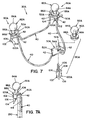
- FIG. 7 is an exploded view of a valve frame, according to an alternative embodiment
- FIG. 7A is an enlarged partially sectioned view of a wireform according to an alternative embodiment
- FIG. 8 is a perspective view of a mounting assembly and a corresponding mounting section, according to an alternative embodiment
- FIG. 9 is a front view of the mounting assembly and the corresponding mounting section of FIG. 8 , wherein said mounting assembly and the corresponding mounting section are in engagement;
- FIG. 10 is a partial cross-sectional view of the mounting assembly engaged with the corresponding mounting section, taken along lines 10 - 10 of FIG. 9 ;
- FIG. 11 is a perspective view of a mounting assembly and a corresponding mounting section, according to another alternative embodiment
- FIG. 12 is a side view of the mounting assembly and the corresponding mounting section of FIG. 11 , wherein said mounting assembly and the corresponding mounting section are in engagement;
- FIG. 13 is a partial cross-sectional view of the mounting assembly and the corresponding mounting section, taken along lines 13 - 13 of FIG. 12 .
- FIG. 14 is a perspective view of a hinged wireform section according to an alternative embodiment
- FIG. 15A is an enlarged cross-sectional view of the hinged wireform section, taken along lines 15 A- 15 A of FIG. 14 , wherein the wireform section is shown in an uncollapsed state;
- FIG. 15B is an enlarged cross-sectional view of the hinged wireform section of FIG. 15A , wherein the wireform section is shown in a collapsed state;
- FIG. 16 is a perspective view of a hinged wireform section according to another alternative embodiment
- FIG. 17A is an enlarged cross-sectional view of the wireform section taken along lines 17 A- 17 A of FIG. 8 , wherein the wireform section is shown in an uncollapsed state;
- FIG. 17B is an enlarged cross-sectional view of the wireform section of FIG. 17A , wherein the wireform is shown in a collapsed state;
- FIGS. 18A-18C illustrate removal of a valve member from a base member using an installation/removal tool.
- the present invention provides improvement to the devices disclosed in U.S. Pat. No. 6,530,952 entitled “Bioprosthetic Cardiovascular Valve System” (issued Mar. 11, 2003) and U.S. Pat. No. 6,569,196 entitled “System for Minimally Invasive Insertion of a Bioprosthetic Heart Valve” (issued May 27, 2003), both of which are fully incorporated herein by reference.
- Disclosed herein are various embodiments of the present invention. It should be understood that the present invention may be practiced using a combination of features from the various embodiments disclosed herein. In the drawings, similar components of the various embodiments will bear the same reference numbers.
- FIG. 1 illustrates a cardiovascular valve assembly 10 according to one embodiment of the present invention.
- Cardiovascular valve assembly 10 is basically comprised of a replaceable valve member 20 and a base member 170 .
- Valve member 20 is generally comprised of a valve frame 30 and a plurality of pericardial leaflets 230 mounted thereto.
- Base member 170 is sewn to a patient using a sewing cuff 270 , as will be described in detail below.
- Replaceable valve member 20 is detachably mountable to base member 170 , as will also be described in detail below.
- valve member 20 is generally comprised of valve frame 30 and a plurality of pericardial leaflets 230 mounted thereto. Pericardial leaflets 230 are omitted from FIGS. 3 and 4 for improved clarity.
- Valve frame 30 includes a wireform comprised of a plurality of wireform sections 40 , and a mounting assembly 80 .
- Each wireform section 40 of valve frame 30 has a generally arcuate shape, and has an end portion 42 at distal ends thereof. In the embodiment shown, each end portion 42 is arranged to form a generally circular loop.
- Wireform sections 40 are preferably made of a medical grade metal wire with suitable elasticity, such as Algiloy, nitinol, stainless steel, platinum, gold, titanium, other biocompatible metals, and combinations thereof. It should be understood that a preferred material for wireform sections 40 has an elasticity such that the material returns to its original shape after being deformed. However, it is contemplated that a material that does not return to its original shape after deformation could also be suitably used.
- Mounting assembly 80 is comprised of a cap 82 and a support member 100 .
- cap 82 has a bulbous portion 84 , a neck 86 and a base 88 .
- a hole 90 extends through cap 82 , as best seen in FIG. 4 .
- Cap 82 is an engagement means for facilitating engagement of mounting assembly 80 with an installation/removal tool, as will be described below.
- Support member 100 comprises a retaining pin 110 and a mounting element 102 .
- Retaining pin 110 includes a split end 112 having locking tabs 114 extending therefrom. Split end 112 compresses to allow retaining pin 110 to be inserted into hole 90 of cap 82 . Locking tabs 114 extend out through hole 90 and lock cap 82 onto support member 100 , as shown in FIG. 1 .
- Mounting element 102 has an inner face 104 , an outer face 106 and a top face 108 .
- mounting element 102 takes the form of a prismatic-shaped “spike” with engagement surfaces formed in inner face 104 .
- Wireform sections 40 are mounted to support member 100 by first mounting end portions 42 of adjacent wireform sections 40 onto retaining pin 110 . Thereafter, cap 82 is slid onto retaining pin 110 to capture end portions 42 between base 88 of cap 82 and top face 108 of mounting element 102 . As indicated above, locking tabs 114 extend out through hole 90 , thereby locking cap 82 onto support member 100 .
- the wireform may be comprised of a single continuous wireform section that is connected with each support member 100 .
- loops may be formed in the single continuous wireform section at appropriate locations for mounting to retaining pins 110 .
- the single continuous wireform section may be connected with the support element by spot welding or other means.
- wireform sections 40 and mounting assemblies 80 While an illustrated embodiment of the present invention shows three (3) wireform sections 40 and three (3) mounting assemblies 80 , it is contemplated that the number of wireform sections 40 and mounting assemblies 80 may be less than or greater than three.
- Base member 170 will now be described in detail with reference to FIGS. 3 and 4 .
- Base member 170 is generally comprised of a plurality of arcuate sections 172 .
- Holes 176 are located along the length of each arcuate section 172 for attachment of a base wrap 250 , as will be described below.
- Distal ends 174 of adjacent arcuate sections 172 join a common mounting section 180 .
- Mounting section 180 includes a mating recess 182 dimensioned to receive mounting element 102 of support member 100 .
- Mounting element 102 and mounting section 180 define interlocking surface means.
- Mounting section 180 has an outer face 186 and an upper face 188 .
- Holes 187 extend through mounting section 180 along the lower end of outer face 186 for attachment of sewing cuff 270 ( FIG. 1 ), as will be described below.
- outer surface 106 is generally flush with outer face 186 of mounting section 180 and top face 108 is generally flush with upper face 188 .
- arcuate sections 172 and mounting sections 180 While an illustrated embodiment shows three (3) arcuate sections 172 and three (3) mounting sections 180 , it is contemplated that the number of arcuate sections 172 and mounting sections 180 may be less than or greater than three.
- a pericardial leaflet 230 and a frame wrap 210 there is shown a pericardial leaflet 230 and a frame wrap 210 .
- Leaflet 230 has a first end 232 and a second end 234 .
- First end 232 is fixed relative to valve frame 30 , as will be described below.
- Second end 234 of leaflet 230 is free to move during ordinary operation of valve member 20 .
- Leaflet 230 also has an inner surface 236 and an outer surface 238 .
- a frame wrap 210 is used to attach each leaflet 230 to wireform sections 40 , as will be described below.
- Frame wrap 210 has a first edge 212 , a second edge 214 , an inner surface 216 , and an outer surface 218 .
- Leaflet 230 and frame wrap 210 are preferably made of a biocompatible, non-thrombogenic material, such as glutaraldehyde-fixed pericardium of bovine, porcine, equine or any other human or animal origin.
- pericardial leaflets 230 are attached to wireform sections 40 by attachment to frame wrap 210 .
- frame wrap 210 is first wrapped around each wireform section 40 , wherein first edge 212 is joined to second edge 214 .
- First edge 212 is stitched to second edge 214 generally along line 215 to capture wireform section 40 , thereby permanently attaching frame wrap 210 to valve frame 30 .
- Outer surface 238 of leaflet 230 is then located adjacent to outer surface 218 of frame wrap 210 .
- First end 232 is stitched to frame wrap 210 generally along line 235 , thereby permanently attaching leaflet 230 to frame wrap 210 .
- end 232 of leaflet 230 extends beyond edges 212 , 214 of frame wrap 210 (e.g., by 1-5 mm) to impede displacement of frame wrap 210 along the length of wireform section 40 . Furthermore, extension of ends 232 beyond edges 212 , 214 of frame wrap 210 allows leaflets 230 to cover any gap that may exist between valve frame 30 and base member 170 when valve member 20 is fully installed in base member 170 . As a result, blood leakage between valve member 20 and base member 170 is prevented.
- Sewing cuff 270 is provided to attach base member 170 to body tissue inside a patient. With particular reference to FIG. 6 , there is shown sewing cuff 270 and a base wrap 250 . Sewing cuff 270 preferably takes the form of a ring having an outer edge 272 and an inner edge 274 . Sewing cuff 270 also has an upper surface 276 . Base wrap 250 is attached to each arcuate section 172 of base member 170 to attach sewing cuff 270 to base member 170 , as will be described below. Base wrap 250 has a first edge 252 , a second edge 254 , an inner surface 256 , and an outer surface 258 . Sewing cuff 270 and base wrap 250 are preferably made of Dacron or other medical grade cloth.
- sewing cuff 270 is attached to base member 170 using base wrap 250 .
- each base wrap 250 is wrapped around an arcuate section 172 of base member 170 .
- First edge 252 is stitched to second edge 254 generally along line 255 to capture each arcuate section 172 , thereby permanently attaching base wrap 250 to base member 170 .
- Holes 176 located along the length of arcuate sections 172 may be used to directly stitch base wrap 250 to base member 170 .
- Upper surface 276 of sewing cuff 270 is located adjacent to outer surface 258 of base wrap 250 , as shown in FIG. 2 .
- Sewing cuff 270 is stitched to base wrap 250 generally along line 275 , thereby permanently attaching sewing cuff 270 to base member 170 .
- outer edge 272 of sewing cuff 270 extends outward from arcuate sections 172 of base member 170 . Holes 187 of mounting sections 180 may be used to stitch sewing cuff 270 directly to base member 170 .
- a mounting assembly 80 A is comprised of a plate 50 A, a cap 82 A, and a support member 100 A.
- Plate 50 A is generally planar, and includes recesses 52 A and a hole 54 A.
- Recesses 52 A are dimensioned to receive end portions 42 of wireform sections 40 .
- end portions 42 are inserted into recesses 52 A and spot welded to plate 50 A. Accordingly, adjacent end portions 42 of wireform sections 40 are joined to a common plate 50 A.
- Hole 54 A is dimensioned to receive a threaded retaining pin 110 A, described below.
- Cap 82 A has a bulbous portion 84 A, a neck 86 A and a base 88 A.
- a threaded recess 90 A extends into cap 82 A from base 88 A.
- Support member 100 A is comprised of threaded retaining pin 110 A and a mounting element 102 .
- Threaded retaining pin 110 A is dimensioned to threadingly engage with threaded hole 90 A.
- Mounting element 102 has been described in detail above.
- retaining pin 110 A is inserted through hole 54 A of plate 50 A, and cap 82 A is then threaded onto retaining pin 110 A. Accordingly, plate 50 A is captured between base 88 A of cap 82 A and top face 108 of mounting element 102 .
- a kink or bend 44 is located in wireform sections 40 proximate to end portion 42 . Kink or bend 44 helps to prevent slippage or dislocation of frame wrap member 210 along wireform section 40 .
- FIGS. 8-10 illustrate a valve frame mounting assembly 120 and a base member mounting section 180 A, according to an alternative embodiment of the present invention.
- mounting assembly 120 is generally comprised of a cap 122 and a mounting element 142 .
- cap 122 has a bulbous portion 124 , a neck 126 and a base 128 .
- Recesses 132 are located in base 128 , and are dimensioned to receive end portions 42 of adjacent wireform sections 40 .
- a slot 130 is formed in base 128 , and is dimensioned to receive a portion of mounting section 180 A, as best seen in FIG. 9 .
- Mounting element 142 takes the form of a pin or bar that extends across slot 130 , as best seen in FIGS. 8 and 9 .
- Mounting section 180 A includes a recess 182 A formed in an upper face 188 A.
- recess 182 A takes the form of a generally L-shaped slot.
- Recess 182 A is dimensioned to receive mounting element 142 to attach mounting assembly 120 to mounting section 180 A.
- Mounting element 142 and mounting section 180 A define interlocking surface means. It should be appreciated that mounting section 180 A has a relatively narrow outer face 186 A.
- FIGS. 11-13 illustrated a valve frame mounting assembly 80 B and a base member mounting section 180 B according to still another alternative embodiment of the present invention.
- mounting assembly 80 B is comprised of a cap 82 B, a plate 50 B, and a mounting element 56 B.
- Cap 82 B includes a bulbous portion 84 B, a neck 86 B and a base 88 B.
- cap 82 B may be attached to plate 50 B by spot welding or by a fastener (e.g., a screw).
- Plate 50 B includes recesses 52 B that are dimensioned to receive end portions 42 of wireform sections 40 .
- mounting element 56 B takes the form of a clip, hook, or latch member that extends from plate 50 B.
- mounting element 56 B includes a downward extending wall 57 B and an inward extending wall or tab 58 B, as best seen in FIGS. 11 and 12 .
- Mounting section 180 B has an outer face 186 B and an upper face 188 B.
- a slot or recess 182 B is formed in outer face 186 B.
- Recess 182 B is dimensioned to receive inward extending tab 58 B of plate 50 B to attach mounting assembly 80 B to mounting section 180 B.
- Mounting element 56 B and mounting section 180 B define interlocking surface means. When tab 58 B is received by recess 182 B, the lower surface of plate 50 B rests on upper face 188 B. It should be appreciated that mounting section 180 B has a relatively narrow outer face 186 B.
- Wireform section 60 is a generally flat ribbon or strip having distal end portions in the form of outward projecting mounting tabs 62 .
- Each mounting tab 62 includes a hole 66 .
- Hole 66 is dimensioned to receive a retaining pin for attachment with a mounting assembly, as described above.
- Holes 65 may be located along the length of wireform section 60 for attachment of base wraps 250 thereto by stitching.
- a notch 68 may be formed therein ( FIG.
- Wireform section 60 is preferably made of a medical grade polymer material, such as poly-ether-ether-ketone (PEEK), polyurethane or polycarbonate.
- PEEK poly-ether-ether-ketone
- the polymer material is preferably fabricated so as to align the molecules along a hinging axis located at notch 68 .
- wireform section 70 also takes the form of a flat ribbon or strip having distal end portions in the form of outward projecting mounting tabs 62 .
- wireform section 70 is comprised of individual wireform portions 70 a and 70 b joined together at or near the center of wireform 70 by a connecting pad 75 ( FIG. 17A ).
- Connecting pad 75 is made of a flexible material that allows wireform portions 70 a and 70 b to flex relative to each other, as shown in FIG. 17B .
- connecting pad 75 forms a hinge for wireform portions 70 a and 70 b .
- Wireform portions 70 a and 70 b are preferably made of a polymer material, such as poly-ether-ether-ketone (PEEK), polyurethane or polycarbonate.
- Connecting pad 75 is preferably made of a polymer material, such as such as poly-ether-ether-ketone (PEEK), polyurethane or polycarbonate.
- the wireform of the present invention may be comprised of a single continuous wireform section.
- a single continuous wireform may take the form of a flat ribbon or strip in a ring-like arrangement, wherein mounting tabs are formed in the single continuous wireform section at appropriate locations.
- cardiovascular valve assembly 10 Assembly and operation of cardiovascular valve assembly 10 will now be described with reference to a cardiovascular valve assembly 10 according to the embodiment shown in FIGS. 1-6 . It should be appreciated that operation of the cardiovascular valve assembly according to alternative embodiments described herein is substantially the same.
- a plurality of frame wraps 210 and leaflets 230 are attached to valve frame 30 , as described above, to form a fully assembled valve member 20 . Furthermore, a plurality of base wraps 250 and sewing cuff 270 are attached to base member 170 , as described above. Thereafter, assembly of cardiovascular valve assembly 10 is completed by engaging valve frame 30 with base member 170 ( FIG. 1 ). In this regard, each mounting element 102 of mounting assemblies 80 is received into a respective mating recess 182 of mounting sections 180 . When assembled, wireform sections 40 of valve frame 30 will extend generally parallel to arcuate sections 172 of base member 170 .
- valve frame 30 may require a small temporary expansion of valve frame 30 in order to fit mounting elements 102 into respective mating recesses 182 . Thereafter, fully assembled cardiovascular valve assembly 10 is sewn to a patient using sewing cuff 270 .
- Tool 300 When it becomes necessary to replace valve member 20 , an installation/removal tool 300 may be used (see FIGS. 18A-18C ).
- Tool 300 includes a plurality of preformed, retractable snares 310 and a plurality of expander elements 320 . In the illustrated embodiment, there are three snares 310 and three expander elements 320 . However, it is contemplated that the number of snares and expander elements may vary depending upon the configuration of cardiovascular valve assembly 10 .
- Each expanding element 320 has an engagement member 322 at a distal end thereof.
- Tool 300 allows for removal and insertion of valve member 20 in a simple pull-out/push-in operation that does not require visualization once tool 300 is attached to the valve member 20 , as will be described below
- valve member 20 Removal of valve member 20 from base member 170 will now be described in detail with reference to FIGS. 18A-18C .
- snares 310 are looped around necks 86 of each cap 82 ( FIG. 18A ). It should be appreciated that the shape and location of cap 82 allows cap 82 to be grabbed by snares 310 even if there is considerable tissue overgrowth.
- mounting elements 102 are disengaged from mounting sections 180 by engaging engagement member 322 of each expanding element 320 with neck 86 of each cap 82 .
- Expanding elements 320 are moved from a retracted position to an expanded position to simultaneously force each mounting assembly 80 outward, thereby disengaging mounting elements 102 from mounting sections 180 .
- valve member 20 is released from base member 170 .
- valve member 20 may then be partially or fully collapsed by moving engagement members 322 from the expanded position to the retracted position, and drawing snares 310 inward, as shown in FIG. 18C . Accordingly, valve member 20 can be conveniently withdrawn from the aorta through a port access system (not shown).
- the port access system may take the form of a temporary Dacron graft sewn onto the vessel.
- a replacement valve member 20 is installed by generally reversing the operation described above for removal.
- valve member 20 is detachable from base member 170 by way of outward deflection of valve frame 30 at mounting assembly 80 . Deflection may occur by use of installation/removal tool 300 , as described above, or alternatively by a surgeon's fingers.
- wireform sections 40 of the valve frame 30 are made of a deformable material and/or include hinge means, as described above.
- wireform sections 40 may be generally rigid (i.e., not be made of a deformable material and/or include any hinge means), and thus do not collapsible as described above.
Abstract
Description
Claims (24)
Priority Applications (4)
| Application Number | Priority Date | Filing Date | Title |
|---|---|---|---|
| US11/296,899 US7758640B2 (en) | 2004-12-16 | 2005-12-08 | Cardiovascular valve assembly |
| AT05027534T ATE402671T1 (en) | 2004-12-16 | 2005-12-15 | CARDIOVASCULAR VALVE PROSTHESIS |
| EP05027534A EP1671608B1 (en) | 2004-12-16 | 2005-12-15 | Cardiovascular valve assembly |
| DE602005008542T DE602005008542D1 (en) | 2004-12-16 | 2005-12-15 | Cardiovascular valve prosthesis |
Applications Claiming Priority (2)
| Application Number | Priority Date | Filing Date | Title |
|---|---|---|---|
| US63660804P | 2004-12-16 | 2004-12-16 | |
| US11/296,899 US7758640B2 (en) | 2004-12-16 | 2005-12-08 | Cardiovascular valve assembly |
Publications (2)
| Publication Number | Publication Date |
|---|---|
| US20060136052A1 US20060136052A1 (en) | 2006-06-22 |
| US7758640B2 true US7758640B2 (en) | 2010-07-20 |
Family
ID=35624128
Family Applications (1)
| Application Number | Title | Priority Date | Filing Date |
|---|---|---|---|
| US11/296,899 Expired - Fee Related US7758640B2 (en) | 2004-12-16 | 2005-12-08 | Cardiovascular valve assembly |
Country Status (4)
| Country | Link |
|---|---|
| US (1) | US7758640B2 (en) |
| EP (1) | EP1671608B1 (en) |
| AT (1) | ATE402671T1 (en) |
| DE (1) | DE602005008542D1 (en) |
Cited By (58)
| Publication number | Priority date | Publication date | Assignee | Title |
|---|---|---|---|---|
| US20100023120A1 (en) * | 2008-04-23 | 2010-01-28 | Holecek Arin N | Tissue attachment devices and methods for prosthetic heart valves |
| US20150272730A1 (en) * | 2014-02-11 | 2015-10-01 | Gilberto Melnick | Modular transcatheter heart valve and implantation method |
| US9186249B2 (en) | 2012-08-10 | 2015-11-17 | Sorin Group Italia S.R.L. | Valve prosthesis and kit |
| US9414913B2 (en) | 2013-10-25 | 2016-08-16 | Medtronic, Inc. | Stented prosthetic heart valve |
| US20160296331A1 (en) * | 2008-09-19 | 2016-10-13 | Edwards Lifesciences Corporation | Surgical heart valves adapted for post implant expansion |
| US9763657B2 (en) | 2010-07-21 | 2017-09-19 | Mitraltech Ltd. | Techniques for percutaneous mitral valve replacement and sealing |
| USD800908S1 (en) | 2016-08-10 | 2017-10-24 | Mitraltech Ltd. | Prosthetic valve element |
| US9895225B2 (en) | 2012-03-23 | 2018-02-20 | Sorin Group Italia S.R.L. | Collapsible valve prosthesis |
| US9974651B2 (en) | 2015-02-05 | 2018-05-22 | Mitral Tech Ltd. | Prosthetic valve with axially-sliding frames |
| US10034747B2 (en) | 2015-08-27 | 2018-07-31 | Medtronic Vascular, Inc. | Prosthetic valve system having a docking component and a prosthetic valve component |
| US10143550B2 (en) | 2013-08-08 | 2018-12-04 | Sorin Group Italia S.R.L. | Heart valve prosthesis |
| USD841812S1 (en) | 2017-08-03 | 2019-02-26 | Cardiovalve Ltd. | Prosthetic heart valve element |
| US10226341B2 (en) | 2011-08-05 | 2019-03-12 | Cardiovalve Ltd. | Implant for heart valve |
| US10245143B2 (en) | 2011-08-05 | 2019-04-02 | Cardiovalve Ltd. | Techniques for percutaneous mitral valve replacement and sealing |
| US10245141B2 (en) | 2014-05-14 | 2019-04-02 | Sorin Group Italia S.R.L. | Implant device and implantation kit |
| US10376361B2 (en) | 2011-08-05 | 2019-08-13 | Cardiovalve Ltd. | Techniques for percutaneous mitral valve replacement and sealing |
| US10390952B2 (en) | 2015-02-05 | 2019-08-27 | Cardiovalve Ltd. | Prosthetic valve with flexible tissue anchor portions |
| US10463478B2 (en) | 2012-12-19 | 2019-11-05 | W. L. Gore & Associates, Inc. | Truncated leaflet for prosthetic heart valves |
| US10492908B2 (en) | 2014-07-30 | 2019-12-03 | Cardiovalve Ltd. | Anchoring of a prosthetic valve |
| US10543085B2 (en) | 2012-12-31 | 2020-01-28 | Edwards Lifesciences Corporation | One-piece heart valve stents adapted for post-implant expansion |
| US10575948B2 (en) | 2017-08-03 | 2020-03-03 | Cardiovalve Ltd. | Prosthetic heart valve |
| US10588745B2 (en) | 2016-06-20 | 2020-03-17 | Medtronic Vascular, Inc. | Modular valve prosthesis, delivery system, and method of delivering and deploying a modular valve prosthesis |
| US10631982B2 (en) | 2013-01-24 | 2020-04-28 | Cardiovale Ltd. | Prosthetic valve and upstream support therefor |
| US10639144B2 (en) | 2012-12-19 | 2020-05-05 | W. L. Gore & Associates, Inc. | Vertical coaptation zone in a planar portion of prosthetic heart valve leaflet |
| US10646333B2 (en) | 2013-10-24 | 2020-05-12 | Medtronic, Inc. | Two-piece valve prosthesis with anchor stent and valve component |
| US10660745B2 (en) | 2012-12-19 | 2020-05-26 | W. L. Gore & Associates, Inc. | Methods for improved prosthetic heart valve with leaflet shelving |
| US10799343B2 (en) | 2015-02-12 | 2020-10-13 | Medtronic, Inc. | Integrated valve assembly and method of delivering and deploying an integrated valve assembly |
| US10856975B2 (en) | 2016-08-10 | 2020-12-08 | Cardiovalve Ltd. | Prosthetic valve with concentric frames |
| US10881507B2 (en) | 2012-12-19 | 2021-01-05 | W. L. Gore & Associates, Inc. | Prosthetic valves, frames and leaflets and methods thereof |
| US10888421B2 (en) | 2017-09-19 | 2021-01-12 | Cardiovalve Ltd. | Prosthetic heart valve with pouch |
| US10959842B2 (en) | 2017-09-12 | 2021-03-30 | W. L. Gore & Associates, Inc. | Leaflet frame attachment for prosthetic valves |
| US10966820B2 (en) | 2012-12-19 | 2021-04-06 | W. L. Gore & Associates, Inc. | Geometric control of bending character in prosthetic heart valve leaflets |
| US10987218B2 (en) | 2017-10-31 | 2021-04-27 | W. L. Gore & Associates, Inc. | Transcatheter deployment systems and associated methods |
| US11020221B2 (en) | 2017-09-27 | 2021-06-01 | W. L. Gore & Associates, Inc. | Prosthetic valve with expandable frame and associated systems and methods |
| US11039917B2 (en) | 2012-12-19 | 2021-06-22 | W. L. Gore & Associates, Inc. | Geometric prosthetic heart valves |
| US11065112B2 (en) | 2014-08-18 | 2021-07-20 | W. L. Gore & Associates, Inc. | Frame with integral sewing cuff for prosthetic valves |
| USD926322S1 (en) | 2018-11-07 | 2021-07-27 | W. L. Gore & Associates, Inc. | Heart valve cover |
| US11090153B2 (en) | 2017-10-13 | 2021-08-17 | W. L. Gore & Associates, Inc. | Telescoping prosthetic valve and delivery system |
| US11109963B2 (en) | 2017-09-27 | 2021-09-07 | W. L. Gore & Associates, Inc. | Prosthetic valves with mechanically coupled leaflets |
| US11109964B2 (en) | 2010-03-10 | 2021-09-07 | Cardiovalve Ltd. | Axially-shortening prosthetic valve |
| US11123183B2 (en) | 2017-10-31 | 2021-09-21 | W. L. Gore & Associates, Inc. | Prosthetic heart valve |
| US11141268B2 (en) | 2009-12-08 | 2021-10-12 | Cardiovalve Ltd. | Prosthetic heart valve with upper and lower skirts |
| US11154397B2 (en) | 2017-10-31 | 2021-10-26 | W. L. Gore & Associates, Inc. | Jacket for surgical heart valve |
| US11166809B2 (en) | 2012-07-25 | 2021-11-09 | W. L. Gore & Associates, Inc. | Everting transcatheter valve and methods |
| US11246704B2 (en) | 2017-08-03 | 2022-02-15 | Cardiovalve Ltd. | Prosthetic heart valve |
| USD944398S1 (en) | 2018-06-13 | 2022-02-22 | Edwards Lifesciences Corporation | Expanded heart valve stent |
| US11291547B2 (en) | 2011-08-05 | 2022-04-05 | Cardiovalve Ltd. | Leaflet clip with collars |
| US11382746B2 (en) | 2017-12-13 | 2022-07-12 | Cardiovalve Ltd. | Prosthetic valve and delivery tool therefor |
| US11413172B2 (en) | 2015-09-01 | 2022-08-16 | Medtronic, Inc. | Stent assemblies including passages to provide blood flow to coronary arteries and methods of delivering and deploying such stent assemblies |
| US11439502B2 (en) | 2017-10-31 | 2022-09-13 | W. L. Gore & Associates, Inc. | Medical valve and leaflet promoting tissue ingrowth |
| US11471276B2 (en) | 2014-09-15 | 2022-10-18 | W. L. Gore & Associates, Inc. | Prosthetic heart valve with retention elements |
| US11497601B2 (en) | 2019-03-01 | 2022-11-15 | W. L. Gore & Associates, Inc. | Telescoping prosthetic valve with retention element |
| US11504231B2 (en) | 2018-05-23 | 2022-11-22 | Corcym S.R.L. | Cardiac valve prosthesis |
| US11633277B2 (en) | 2018-01-10 | 2023-04-25 | Cardiovalve Ltd. | Temperature-control during crimping of an implant |
| US11653910B2 (en) | 2010-07-21 | 2023-05-23 | Cardiovalve Ltd. | Helical anchor implantation |
| US11707355B2 (en) | 2020-05-28 | 2023-07-25 | Medtronic, Inc. | Modular heart valve prosthesis |
| US11793633B2 (en) | 2017-08-03 | 2023-10-24 | Cardiovalve Ltd. | Prosthetic heart valve |
| US11937795B2 (en) | 2016-02-16 | 2024-03-26 | Cardiovalve Ltd. | Techniques for providing a replacement valve and transseptal communication |
Families Citing this family (63)
| Publication number | Priority date | Publication date | Assignee | Title |
|---|---|---|---|---|
| US6602286B1 (en) | 2000-10-26 | 2003-08-05 | Ernst Peter Strecker | Implantable valve system |
| US7201771B2 (en) | 2001-12-27 | 2007-04-10 | Arbor Surgical Technologies, Inc. | Bioprosthetic heart valve |
| US6752828B2 (en) | 2002-04-03 | 2004-06-22 | Scimed Life Systems, Inc. | Artificial valve |
| US7959674B2 (en) | 2002-07-16 | 2011-06-14 | Medtronic, Inc. | Suture locking assembly and method of use |
| US8551162B2 (en) | 2002-12-20 | 2013-10-08 | Medtronic, Inc. | Biologically implantable prosthesis |
| US6945957B2 (en) | 2002-12-30 | 2005-09-20 | Scimed Life Systems, Inc. | Valve treatment catheter and methods |
| US8021421B2 (en) | 2003-08-22 | 2011-09-20 | Medtronic, Inc. | Prosthesis heart valve fixturing device |
| US7556647B2 (en) | 2003-10-08 | 2009-07-07 | Arbor Surgical Technologies, Inc. | Attachment device and methods of using the same |
| US8128681B2 (en) | 2003-12-19 | 2012-03-06 | Boston Scientific Scimed, Inc. | Venous valve apparatus, system, and method |
| US7854761B2 (en) | 2003-12-19 | 2010-12-21 | Boston Scientific Scimed, Inc. | Methods for venous valve replacement with a catheter |
| US7566343B2 (en) | 2004-09-02 | 2009-07-28 | Boston Scientific Scimed, Inc. | Cardiac valve, system, and method |
| US7758640B2 (en) | 2004-12-16 | 2010-07-20 | Valvexchange Inc. | Cardiovascular valve assembly |
| US20060173490A1 (en) | 2005-02-01 | 2006-08-03 | Boston Scientific Scimed, Inc. | Filter system and method |
| US7854755B2 (en) | 2005-02-01 | 2010-12-21 | Boston Scientific Scimed, Inc. | Vascular catheter, system, and method |
| US7780722B2 (en) | 2005-02-07 | 2010-08-24 | Boston Scientific Scimed, Inc. | Venous valve apparatus, system, and method |
| US7670368B2 (en) | 2005-02-07 | 2010-03-02 | Boston Scientific Scimed, Inc. | Venous valve apparatus, system, and method |
| US7867274B2 (en) | 2005-02-23 | 2011-01-11 | Boston Scientific Scimed, Inc. | Valve apparatus, system and method |
| US7513909B2 (en) | 2005-04-08 | 2009-04-07 | Arbor Surgical Technologies, Inc. | Two-piece prosthetic valves with snap-in connection and methods for use |
| US7722666B2 (en) | 2005-04-15 | 2010-05-25 | Boston Scientific Scimed, Inc. | Valve apparatus, system and method |
| WO2006130505A2 (en) | 2005-05-27 | 2006-12-07 | Arbor Surgical Technologies, Inc. | Gasket with collar for prosthetic heart valves and methods for using them |
| US8012198B2 (en) | 2005-06-10 | 2011-09-06 | Boston Scientific Scimed, Inc. | Venous valve, system, and method |
| US7569071B2 (en) | 2005-09-21 | 2009-08-04 | Boston Scientific Scimed, Inc. | Venous valve, system, and method with sinus pocket |
| US7799038B2 (en) | 2006-01-20 | 2010-09-21 | Boston Scientific Scimed, Inc. | Translumenal apparatus, system, and method |
| US7967857B2 (en) | 2006-01-27 | 2011-06-28 | Medtronic, Inc. | Gasket with spring collar for prosthetic heart valves and methods for making and using them |
| EP2023860A2 (en) | 2006-04-29 | 2009-02-18 | Arbor Surgical Technologies, Inc. | Multiple component prosthetic heart valve assemblies and apparatus and methods for delivering them |
| US20080004696A1 (en) | 2006-06-29 | 2008-01-03 | Valvexchange Inc. | Cardiovascular valve assembly with resizable docking station |
| US8133270B2 (en) | 2007-01-08 | 2012-03-13 | California Institute Of Technology | In-situ formation of a valve |
| WO2008088835A1 (en) * | 2007-01-18 | 2008-07-24 | Valvexchange Inc. | Tools for removal and installation of exchangeable cardiovascular valves |
| JP5313928B2 (en) | 2007-02-05 | 2013-10-09 | ボストン サイエンティフィック リミテッド | Percutaneous valves and systems |
| US9504568B2 (en) | 2007-02-16 | 2016-11-29 | Medtronic, Inc. | Replacement prosthetic heart valves and methods of implantation |
| US8092523B2 (en) * | 2007-03-12 | 2012-01-10 | St. Jude Medical, Inc. | Prosthetic heart valves with flexible leaflets |
| US8409274B2 (en) * | 2007-04-26 | 2013-04-02 | St. Jude Medical, Inc. | Techniques for attaching flexible leaflets of prosthetic heart valves to supporting structures |
| US20080294247A1 (en) * | 2007-05-25 | 2008-11-27 | Medical Entrepreneurs Ii, Inc. | Prosthetic Heart Valve |
| US8828079B2 (en) | 2007-07-26 | 2014-09-09 | Boston Scientific Scimed, Inc. | Circulatory valve, system and method |
| US7892276B2 (en) | 2007-12-21 | 2011-02-22 | Boston Scientific Scimed, Inc. | Valve with delayed leaflet deployment |
| US9039756B2 (en) | 2008-07-21 | 2015-05-26 | Jenesis Surgical, Llc | Repositionable endoluminal support structure and its applications |
| AU2009274131B2 (en) | 2008-07-21 | 2015-06-04 | Jennifer K. White | Repositionable endoluminal support structure and its applications |
| US8925164B2 (en) * | 2008-09-12 | 2015-01-06 | Valvexchange Inc. | Valve assembly with exchangeable valve member and a tool set for exchanging the valve member |
| US9402720B2 (en) | 2009-01-12 | 2016-08-02 | Valve Medical Ltd. | Modular percutaneous valve structure and delivery method |
| US8579964B2 (en) | 2010-05-05 | 2013-11-12 | Neovasc Inc. | Transcatheter mitral valve prosthesis |
| ES2861100T3 (en) * | 2010-05-10 | 2021-10-05 | Edwards Lifesciences Corp | Prosthetic heart valve |
| US9308087B2 (en) | 2011-04-28 | 2016-04-12 | Neovasc Tiara Inc. | Sequentially deployed transcatheter mitral valve prosthesis |
| US9554897B2 (en) | 2011-04-28 | 2017-01-31 | Neovasc Tiara Inc. | Methods and apparatus for engaging a valve prosthesis with tissue |
| CA2855943C (en) * | 2011-07-29 | 2019-10-29 | Carnegie Mellon University | Artificial valved conduits for cardiac reconstructive procedures and methods for their production |
| US9668859B2 (en) | 2011-08-05 | 2017-06-06 | California Institute Of Technology | Percutaneous heart valve delivery systems |
| US9345573B2 (en) | 2012-05-30 | 2016-05-24 | Neovasc Tiara Inc. | Methods and apparatus for loading a prosthesis onto a delivery system |
| CN103536377B (en) * | 2012-07-17 | 2018-05-04 | 李莉 | It is a kind of that the heart biology valve for replacing leaflet is repeated by Minimally Invasive Surgery |
| CN107184292B (en) | 2013-03-13 | 2020-07-10 | 爱德华兹生命科学卡迪尔克有限责任公司 | Articulating commissure valve stents and methods |
| US9744037B2 (en) | 2013-03-15 | 2017-08-29 | California Institute Of Technology | Handle mechanism and functionality for repositioning and retrieval of transcatheter heart valves |
| US9572665B2 (en) | 2013-04-04 | 2017-02-21 | Neovasc Tiara Inc. | Methods and apparatus for delivering a prosthetic valve to a beating heart |
| US9867611B2 (en) * | 2013-09-05 | 2018-01-16 | St. Jude Medical, Cardiology Division, Inc. | Anchoring studs for transcatheter valve implantation |
| US9700442B2 (en) | 2013-11-11 | 2017-07-11 | Edwards Lifesciences Cardiaq Llc | Methods for manufacturing a stent frame |
| US10022225B2 (en) * | 2014-07-23 | 2018-07-17 | Clemson University Research Foundation | Self-adjusting tissue holder |
| AU2015364334B2 (en) * | 2014-12-18 | 2018-11-01 | Edwards Lifesciences Corporation | Prosthetic valves with mechanically coupled leaflets |
| US9855141B2 (en) | 2014-12-18 | 2018-01-02 | W. L. Gore & Associates, Inc. | Prosthetic valves with mechanically coupled leaflets |
| CN108882981B (en) | 2016-01-29 | 2021-08-10 | 内奥瓦斯克迪亚拉公司 | Prosthetic valve for preventing outflow obstruction |
| CN109996581B (en) | 2016-11-21 | 2021-10-15 | 内奥瓦斯克迪亚拉公司 | Methods and systems for rapid retrieval of transcatheter heart valve delivery systems |
| CN111263622A (en) | 2017-08-25 | 2020-06-09 | 内奥瓦斯克迪亚拉公司 | Sequentially deployed transcatheter mitral valve prosthesis |
| EP3876870B1 (en) | 2018-11-08 | 2023-12-20 | Neovasc Tiara Inc. | Ventricular deployment of a transcatheter mitral valve prosthesis |
| EP3946163A4 (en) | 2019-04-01 | 2022-12-21 | Neovasc Tiara Inc. | Controllably deployable prosthetic valve |
| EP3952792A4 (en) | 2019-04-10 | 2023-01-04 | Neovasc Tiara Inc. | Prosthetic valve with natural blood flow |
| CN114025813A (en) | 2019-05-20 | 2022-02-08 | 内奥瓦斯克迪亚拉公司 | Introducer with hemostatic mechanism |
| WO2020257643A1 (en) | 2019-06-20 | 2020-12-24 | Neovasc Tiara Inc. | Low profile prosthetic mitral valve |
Citations (75)
| Publication number | Priority date | Publication date | Assignee | Title |
|---|---|---|---|---|
| US3839741A (en) * | 1972-11-17 | 1974-10-08 | J Haller | Heart valve and retaining means therefor |
| US3898701A (en) | 1974-01-17 | 1975-08-12 | Russa Joseph | Implantable heart valve |
| US4056854A (en) | 1976-09-28 | 1977-11-08 | The United States Of America As Represented By The Department Of Health, Education And Welfare | Aortic heart valve catheter |
| US4501030A (en) | 1981-08-17 | 1985-02-26 | American Hospital Supply Corporation | Method of leaflet attachment for prosthetic heart valves |
| US4506394A (en) | 1983-01-13 | 1985-03-26 | Molrose Management, Ltd. | Cardiac valve prosthesis holder |
| US4535483A (en) * | 1983-01-17 | 1985-08-20 | Hemex, Inc. | Suture rings for heart valves |
| US4680031A (en) * | 1982-11-29 | 1987-07-14 | Tascon Medical Technology Corporation | Heart valve prosthesis |
| US4687483A (en) * | 1984-09-28 | 1987-08-18 | University Court Of The University Of Glasgow | Heart valve prosthesis |
| US4705516A (en) * | 1983-04-20 | 1987-11-10 | Barone Hector D | Setting for a cardiac valve |
| US4725274A (en) * | 1986-10-24 | 1988-02-16 | Baxter Travenol Laboratories, Inc. | Prosthetic heart valve |
| US4733665A (en) | 1985-11-07 | 1988-03-29 | Expandable Grafts Partnership | Expandable intraluminal graft, and method and apparatus for implanting an expandable intraluminal graft |
| US4790843A (en) | 1986-06-16 | 1988-12-13 | Baxter Travenol Laboratories, Inc. | Prosthetic heart valve assembly |
| US4851000A (en) * | 1987-07-31 | 1989-07-25 | Pacific Biomedical Holdings, Ltd. | Bioprosthetic valve stent |
| US4909789A (en) | 1986-03-28 | 1990-03-20 | Olympus Optical Co., Ltd. | Observation assisting forceps |
| US4917698A (en) | 1988-12-22 | 1990-04-17 | Baxter International Inc. | Multi-segmented annuloplasty ring prosthesis |
| US5037427A (en) | 1987-03-25 | 1991-08-06 | Terumo Kabushiki Kaisha | Method of implanting a stent within a tubular organ of a living body and of removing same |
| US5061275A (en) | 1986-04-21 | 1991-10-29 | Medinvent S.A. | Self-expanding prosthesis |
| US5071431A (en) | 1990-11-07 | 1991-12-10 | Carbomedics, Inc. | Suture rings for heart valves and method of securing suture rings to heart valves |
| US5113846A (en) | 1990-07-03 | 1992-05-19 | Richard Wolf Gmbh | Organ manipulator |
| US5163953A (en) | 1992-02-10 | 1992-11-17 | Vince Dennis J | Toroidal artificial heart valve stent |
| US5197978A (en) | 1991-04-26 | 1993-03-30 | Advanced Coronary Technology, Inc. | Removable heat-recoverable tissue supporting device |
| US5312360A (en) | 1990-11-20 | 1994-05-17 | Innerdyne Medical, Inc. | Tension guide and dilator |
| US5411552A (en) | 1990-05-18 | 1995-05-02 | Andersen; Henning R. | Valve prothesis for implantation in the body and a catheter for implanting such valve prothesis |
| US5476510A (en) | 1994-04-21 | 1995-12-19 | Medtronic, Inc. | Holder for heart valve |
| WO1996014032A1 (en) * | 1994-11-02 | 1996-05-17 | Duran Carlos M G | Bioprosthetic heart valve with absorbable stent |
| US5545214A (en) | 1991-07-16 | 1996-08-13 | Heartport, Inc. | Endovascular aortic valve replacement |
| US5549665A (en) * | 1993-06-18 | 1996-08-27 | London Health Association | Bioprostethic valve |
| US5554185A (en) | 1994-07-18 | 1996-09-10 | Block; Peter C. | Inflatable prosthetic cardiovascular valve for percutaneous transluminal implantation of same |
| US5571174A (en) | 1991-01-24 | 1996-11-05 | Autogenics | Method of assembling a tissue heart valve |
| US5593424A (en) | 1994-08-10 | 1997-01-14 | Segmed, Inc. | Apparatus and method for reducing and stabilizing the circumference of a vascular structure |
| US5607446A (en) | 1995-01-31 | 1997-03-04 | Beehler; Cecil C. | Pupil dilator |
| US5662676A (en) | 1992-06-24 | 1997-09-02 | K.U. Leuven Research & Development | Instrument set for laparoscopic hysterectomy |
| US5718725A (en) | 1992-12-03 | 1998-02-17 | Heartport, Inc. | Devices and methods for intracardiac procedures |
| US5755783A (en) | 1996-07-29 | 1998-05-26 | Stobie; Robert | Suture rings for rotatable artificial heart valves |
| US5807405A (en) | 1995-09-11 | 1998-09-15 | St. Jude Medical, Inc. | Apparatus for attachment of heart valve holder to heart valve prosthesis |
| US5840081A (en) | 1990-05-18 | 1998-11-24 | Andersen; Henning Rud | System and method for implanting cardiac valves |
| US5843181A (en) | 1994-04-18 | 1998-12-01 | Hancock Jaffe Laboratories | Biological material pre-fixation treatment |
| US5855601A (en) | 1996-06-21 | 1999-01-05 | The Trustees Of Columbia University In The City Of New York | Artificial heart valve and method and device for implanting the same |
| US5910170A (en) * | 1997-12-17 | 1999-06-08 | St. Jude Medical, Inc. | Prosthetic heart valve stent utilizing mounting clips |
| WO1999033414A1 (en) | 1997-12-29 | 1999-07-08 | Ivan Vesely | System for minimally invasive insertion of a bioprosthetic heart valve |
| US5928281A (en) * | 1997-03-27 | 1999-07-27 | Baxter International Inc. | Tissue heart valves |
| US5957949A (en) | 1997-05-01 | 1999-09-28 | World Medical Manufacturing Corp. | Percutaneous placement valve stent |
| US5961545A (en) | 1997-01-17 | 1999-10-05 | Meadox Medicals, Inc. | EPTFE graft-stent composite device |
| US5968070A (en) | 1995-02-22 | 1999-10-19 | Cordis Corporation | Covered expanding mesh stent |
| WO1999053845A1 (en) * | 1998-04-20 | 1999-10-28 | St. Jude Medical, Inc. | Driver tool for heart valve prosthesis fasteners |
| US6071263A (en) | 1992-03-02 | 2000-06-06 | Kirkman; Thomas R. | Apparatus and method for retaining a catheter in a blood vessel in a fixed position |
| WO2000047139A1 (en) | 1999-02-10 | 2000-08-17 | Heartport, Inc. | Methods and devices for implanting cardiac valves |
| US6106550A (en) | 1998-07-10 | 2000-08-22 | Sulzer Carbomedics Inc. | Implantable attaching ring |
| US6168616B1 (en) | 1997-06-02 | 2001-01-02 | Global Vascular Concepts | Manually expandable stent |
| US6197054B1 (en) | 1998-09-01 | 2001-03-06 | Sulzer Carbomedics Inc. | Sutureless cuff for heart valves |
| US6217585B1 (en) | 1996-08-16 | 2001-04-17 | Converge Medical, Inc. | Mechanical stent and graft delivery system |
| US20010002445A1 (en) * | 1997-12-29 | 2001-05-31 | The Cleveland Clinic Foundation | Bioprosthetic cardiovascular valve system |
| US6249952B1 (en) | 1997-08-04 | 2001-06-26 | Scimed Life Systems, Inc. | Method for manufacturing an expandable stent |
| US6312465B1 (en) | 1999-07-23 | 2001-11-06 | Sulzer Carbomedics Inc. | Heart valve prosthesis with a resiliently deformable retaining member |
| US6371983B1 (en) * | 1999-10-04 | 2002-04-16 | Ernest Lane | Bioprosthetic heart valve |
| US20020055775A1 (en) * | 1999-01-26 | 2002-05-09 | Alain F. Carpentier | Flexible heart valve |
| US6454799B1 (en) | 2000-04-06 | 2002-09-24 | Edwards Lifesciences Corporation | Minimally-invasive heart valves and methods of use |
| US6461382B1 (en) | 2000-09-22 | 2002-10-08 | Edwards Lifesciences Corporation | Flexible heart valve having moveable commissures |
| US6562065B1 (en) | 1998-03-30 | 2003-05-13 | Conor Medsystems, Inc. | Expandable medical device with beneficial agent delivery mechanism |
| US6579305B1 (en) | 1995-12-07 | 2003-06-17 | Medtronic Ave, Inc. | Method and apparatus for delivery deployment and retrieval of a stent comprising shape-memory material |
| US6663664B1 (en) * | 2000-10-26 | 2003-12-16 | Advanced Cardiovascular Systems, Inc. | Self-expanding stent with time variable radial force |
| US20040030381A1 (en) | 2002-07-16 | 2004-02-12 | Shu Mark C.S. | Heart valve prosthesis |
| US6733525B2 (en) * | 2001-03-23 | 2004-05-11 | Edwards Lifesciences Corporation | Rolled minimally-invasive heart valves and methods of use |
| US20040122514A1 (en) * | 2002-12-20 | 2004-06-24 | Fogarty Thomas J. | Biologically implantable prosthesis and methods of using the same |
| US20040186563A1 (en) * | 2003-03-18 | 2004-09-23 | Lobbi Mario M. | Minimally-invasive heart valve with cusp positioners |
| US20040225356A1 (en) | 2003-05-09 | 2004-11-11 | Frater Robert W. | Flexible heart valve |
| US20050075717A1 (en) * | 2003-10-06 | 2005-04-07 | Nguyen Tuoc Tan | Minimally invasive valve replacement system |
| US20050159811A1 (en) | 2001-12-27 | 2005-07-21 | Ernest Lane | Bioprosthetic heart valve |
| US20050228494A1 (en) * | 2004-03-29 | 2005-10-13 | Salvador Marquez | Controlled separation heart valve frame |
| US20060136052A1 (en) | 2004-12-16 | 2006-06-22 | Valvexchange Inc. | Cardiovascular valve assembly |
| WO2006127756A2 (en) | 2005-05-24 | 2006-11-30 | Edwards Lifesciences Corporation | Rapid deployment prosthetic heart valve |
| US20080004696A1 (en) | 2006-06-29 | 2008-01-03 | Valvexchange Inc. | Cardiovascular valve assembly with resizable docking station |
| WO2008051428A2 (en) | 2006-10-23 | 2008-05-02 | Valvexchange Inc. | Cardiovascular valve and assembly |
| USRE40377E1 (en) * | 1996-02-23 | 2008-06-10 | Cardiovascular Technologies Llc | Means and method of replacing a heart valve in a minimally invasive manner |
| WO2008088835A1 (en) | 2007-01-18 | 2008-07-24 | Valvexchange Inc. | Tools for removal and installation of exchangeable cardiovascular valves |
-
2005
- 2005-12-08 US US11/296,899 patent/US7758640B2/en not_active Expired - Fee Related
- 2005-12-15 DE DE602005008542T patent/DE602005008542D1/en active Active
- 2005-12-15 AT AT05027534T patent/ATE402671T1/en not_active IP Right Cessation
- 2005-12-15 EP EP05027534A patent/EP1671608B1/en not_active Not-in-force
Patent Citations (88)
| Publication number | Priority date | Publication date | Assignee | Title |
|---|---|---|---|---|
| US3839741A (en) * | 1972-11-17 | 1974-10-08 | J Haller | Heart valve and retaining means therefor |
| US3898701A (en) | 1974-01-17 | 1975-08-12 | Russa Joseph | Implantable heart valve |
| US4056854A (en) | 1976-09-28 | 1977-11-08 | The United States Of America As Represented By The Department Of Health, Education And Welfare | Aortic heart valve catheter |
| US4501030A (en) | 1981-08-17 | 1985-02-26 | American Hospital Supply Corporation | Method of leaflet attachment for prosthetic heart valves |
| US4680031A (en) * | 1982-11-29 | 1987-07-14 | Tascon Medical Technology Corporation | Heart valve prosthesis |
| US4506394A (en) | 1983-01-13 | 1985-03-26 | Molrose Management, Ltd. | Cardiac valve prosthesis holder |
| US4535483A (en) * | 1983-01-17 | 1985-08-20 | Hemex, Inc. | Suture rings for heart valves |
| US4705516A (en) * | 1983-04-20 | 1987-11-10 | Barone Hector D | Setting for a cardiac valve |
| US4687483A (en) * | 1984-09-28 | 1987-08-18 | University Court Of The University Of Glasgow | Heart valve prosthesis |
| US4733665C2 (en) | 1985-11-07 | 2002-01-29 | Expandable Grafts Partnership | Expandable intraluminal graft and method and apparatus for implanting an expandable intraluminal graft |
| US4733665A (en) | 1985-11-07 | 1988-03-29 | Expandable Grafts Partnership | Expandable intraluminal graft, and method and apparatus for implanting an expandable intraluminal graft |
| US4733665B1 (en) | 1985-11-07 | 1994-01-11 | Expandable Grafts Partnership | Expandable intraluminal graft,and method and apparatus for implanting an expandable intraluminal graft |
| US4909789A (en) | 1986-03-28 | 1990-03-20 | Olympus Optical Co., Ltd. | Observation assisting forceps |
| US5061275A (en) | 1986-04-21 | 1991-10-29 | Medinvent S.A. | Self-expanding prosthesis |
| US4790843A (en) | 1986-06-16 | 1988-12-13 | Baxter Travenol Laboratories, Inc. | Prosthetic heart valve assembly |
| US4725274A (en) * | 1986-10-24 | 1988-02-16 | Baxter Travenol Laboratories, Inc. | Prosthetic heart valve |
| US5037427A (en) | 1987-03-25 | 1991-08-06 | Terumo Kabushiki Kaisha | Method of implanting a stent within a tubular organ of a living body and of removing same |
| US4851000A (en) * | 1987-07-31 | 1989-07-25 | Pacific Biomedical Holdings, Ltd. | Bioprosthetic valve stent |
| US4917698A (en) | 1988-12-22 | 1990-04-17 | Baxter International Inc. | Multi-segmented annuloplasty ring prosthesis |
| US5411552A (en) | 1990-05-18 | 1995-05-02 | Andersen; Henning R. | Valve prothesis for implantation in the body and a catheter for implanting such valve prothesis |
| US5840081A (en) | 1990-05-18 | 1998-11-24 | Andersen; Henning Rud | System and method for implanting cardiac valves |
| US6168614B1 (en) | 1990-05-18 | 2001-01-02 | Heartport, Inc. | Valve prosthesis for implantation in the body |
| US5113846A (en) | 1990-07-03 | 1992-05-19 | Richard Wolf Gmbh | Organ manipulator |
| US5071431A (en) | 1990-11-07 | 1991-12-10 | Carbomedics, Inc. | Suture rings for heart valves and method of securing suture rings to heart valves |
| US5312360A (en) | 1990-11-20 | 1994-05-17 | Innerdyne Medical, Inc. | Tension guide and dilator |
| US5571174A (en) | 1991-01-24 | 1996-11-05 | Autogenics | Method of assembling a tissue heart valve |
| US5197978A (en) | 1991-04-26 | 1993-03-30 | Advanced Coronary Technology, Inc. | Removable heat-recoverable tissue supporting device |
| US5197978B1 (en) | 1991-04-26 | 1996-05-28 | Advanced Coronary Tech | Removable heat-recoverable tissue supporting device |
| US5545214A (en) | 1991-07-16 | 1996-08-13 | Heartport, Inc. | Endovascular aortic valve replacement |
| US5163953A (en) | 1992-02-10 | 1992-11-17 | Vince Dennis J | Toroidal artificial heart valve stent |
| US6071263A (en) | 1992-03-02 | 2000-06-06 | Kirkman; Thomas R. | Apparatus and method for retaining a catheter in a blood vessel in a fixed position |
| US5662676A (en) | 1992-06-24 | 1997-09-02 | K.U. Leuven Research & Development | Instrument set for laparoscopic hysterectomy |
| US5718725A (en) | 1992-12-03 | 1998-02-17 | Heartport, Inc. | Devices and methods for intracardiac procedures |
| US5549665A (en) * | 1993-06-18 | 1996-08-27 | London Health Association | Bioprostethic valve |
| US5843181A (en) | 1994-04-18 | 1998-12-01 | Hancock Jaffe Laboratories | Biological material pre-fixation treatment |
| US5476510A (en) | 1994-04-21 | 1995-12-19 | Medtronic, Inc. | Holder for heart valve |
| US5554185A (en) | 1994-07-18 | 1996-09-10 | Block; Peter C. | Inflatable prosthetic cardiovascular valve for percutaneous transluminal implantation of same |
| US5593424A (en) | 1994-08-10 | 1997-01-14 | Segmed, Inc. | Apparatus and method for reducing and stabilizing the circumference of a vascular structure |
| WO1996014032A1 (en) * | 1994-11-02 | 1996-05-17 | Duran Carlos M G | Bioprosthetic heart valve with absorbable stent |
| US5607446A (en) | 1995-01-31 | 1997-03-04 | Beehler; Cecil C. | Pupil dilator |
| US5968070A (en) | 1995-02-22 | 1999-10-19 | Cordis Corporation | Covered expanding mesh stent |
| US5807405A (en) | 1995-09-11 | 1998-09-15 | St. Jude Medical, Inc. | Apparatus for attachment of heart valve holder to heart valve prosthesis |
| US6579305B1 (en) | 1995-12-07 | 2003-06-17 | Medtronic Ave, Inc. | Method and apparatus for delivery deployment and retrieval of a stent comprising shape-memory material |
| USRE40377E1 (en) * | 1996-02-23 | 2008-06-10 | Cardiovascular Technologies Llc | Means and method of replacing a heart valve in a minimally invasive manner |
| US5855601A (en) | 1996-06-21 | 1999-01-05 | The Trustees Of Columbia University In The City Of New York | Artificial heart valve and method and device for implanting the same |
| US5755783A (en) | 1996-07-29 | 1998-05-26 | Stobie; Robert | Suture rings for rotatable artificial heart valves |
| US6143025A (en) * | 1996-07-29 | 2000-11-07 | Edwards Lifesciences Corporation | Suture rings for rotatable artificial heart valves |
| US6217585B1 (en) | 1996-08-16 | 2001-04-17 | Converge Medical, Inc. | Mechanical stent and graft delivery system |
| US5961545A (en) | 1997-01-17 | 1999-10-05 | Meadox Medicals, Inc. | EPTFE graft-stent composite device |
| US5928281A (en) * | 1997-03-27 | 1999-07-27 | Baxter International Inc. | Tissue heart valves |
| US5957949A (en) | 1997-05-01 | 1999-09-28 | World Medical Manufacturing Corp. | Percutaneous placement valve stent |
| US6168616B1 (en) | 1997-06-02 | 2001-01-02 | Global Vascular Concepts | Manually expandable stent |
| US6249952B1 (en) | 1997-08-04 | 2001-06-26 | Scimed Life Systems, Inc. | Method for manufacturing an expandable stent |
| US5910170A (en) * | 1997-12-17 | 1999-06-08 | St. Jude Medical, Inc. | Prosthetic heart valve stent utilizing mounting clips |
| US20060135964A1 (en) | 1997-12-29 | 2006-06-22 | The Cleveland Clinic Foundation | Bioprosthetic cardiovascular valve system |
| WO1999033414A1 (en) | 1997-12-29 | 1999-07-08 | Ivan Vesely | System for minimally invasive insertion of a bioprosthetic heart valve |
| US6530952B2 (en) | 1997-12-29 | 2003-03-11 | The Cleveland Clinic Foundation | Bioprosthetic cardiovascular valve system |
| US20010002445A1 (en) * | 1997-12-29 | 2001-05-31 | The Cleveland Clinic Foundation | Bioprosthetic cardiovascular valve system |
| US20030125793A1 (en) | 1997-12-29 | 2003-07-03 | The Cleveland Clinic Foundation | Bioprosthetic cardiovascular valve system |
| US6569196B1 (en) | 1997-12-29 | 2003-05-27 | The Cleveland Clinic Foundation | System for minimally invasive insertion of a bioprosthetic heart valve |
| US7011681B2 (en) | 1997-12-29 | 2006-03-14 | The Cleveland Clinic Foundation | Bioprosthetic cardiovascular valve system |
| US6562065B1 (en) | 1998-03-30 | 2003-05-13 | Conor Medsystems, Inc. | Expandable medical device with beneficial agent delivery mechanism |
| WO1999053845A1 (en) * | 1998-04-20 | 1999-10-28 | St. Jude Medical, Inc. | Driver tool for heart valve prosthesis fasteners |
| US6074418A (en) * | 1998-04-20 | 2000-06-13 | St. Jude Medical, Inc. | Driver tool for heart valve prosthesis fasteners |
| US6106550A (en) | 1998-07-10 | 2000-08-22 | Sulzer Carbomedics Inc. | Implantable attaching ring |
| US6197054B1 (en) | 1998-09-01 | 2001-03-06 | Sulzer Carbomedics Inc. | Sutureless cuff for heart valves |
| US20020055775A1 (en) * | 1999-01-26 | 2002-05-09 | Alain F. Carpentier | Flexible heart valve |
| WO2000047139A1 (en) | 1999-02-10 | 2000-08-17 | Heartport, Inc. | Methods and devices for implanting cardiac valves |
| US6312465B1 (en) | 1999-07-23 | 2001-11-06 | Sulzer Carbomedics Inc. | Heart valve prosthesis with a resiliently deformable retaining member |
| US6371983B1 (en) * | 1999-10-04 | 2002-04-16 | Ernest Lane | Bioprosthetic heart valve |
| US6454799B1 (en) | 2000-04-06 | 2002-09-24 | Edwards Lifesciences Corporation | Minimally-invasive heart valves and methods of use |
| US20040186565A1 (en) | 2000-04-06 | 2004-09-23 | Stefan Schreck | Minimally-invasive heart valves with wireforms |
| US20020198594A1 (en) * | 2000-04-06 | 2002-12-26 | Stefan Schreck | Minimally-invasive heart valves and methods of use |
| US6461382B1 (en) | 2000-09-22 | 2002-10-08 | Edwards Lifesciences Corporation | Flexible heart valve having moveable commissures |
| US6663664B1 (en) * | 2000-10-26 | 2003-12-16 | Advanced Cardiovascular Systems, Inc. | Self-expanding stent with time variable radial force |
| US6733525B2 (en) * | 2001-03-23 | 2004-05-11 | Edwards Lifesciences Corporation | Rolled minimally-invasive heart valves and methods of use |
| US20050159811A1 (en) | 2001-12-27 | 2005-07-21 | Ernest Lane | Bioprosthetic heart valve |
| US20040030381A1 (en) | 2002-07-16 | 2004-02-12 | Shu Mark C.S. | Heart valve prosthesis |
| US20040122514A1 (en) * | 2002-12-20 | 2004-06-24 | Fogarty Thomas J. | Biologically implantable prosthesis and methods of using the same |
| US20040186563A1 (en) * | 2003-03-18 | 2004-09-23 | Lobbi Mario M. | Minimally-invasive heart valve with cusp positioners |
| US20040225356A1 (en) | 2003-05-09 | 2004-11-11 | Frater Robert W. | Flexible heart valve |
| US20050075717A1 (en) * | 2003-10-06 | 2005-04-07 | Nguyen Tuoc Tan | Minimally invasive valve replacement system |
| US20050228494A1 (en) * | 2004-03-29 | 2005-10-13 | Salvador Marquez | Controlled separation heart valve frame |
| US20060136052A1 (en) | 2004-12-16 | 2006-06-22 | Valvexchange Inc. | Cardiovascular valve assembly |
| WO2006127756A2 (en) | 2005-05-24 | 2006-11-30 | Edwards Lifesciences Corporation | Rapid deployment prosthetic heart valve |
| US20080004696A1 (en) | 2006-06-29 | 2008-01-03 | Valvexchange Inc. | Cardiovascular valve assembly with resizable docking station |
| WO2008051428A2 (en) | 2006-10-23 | 2008-05-02 | Valvexchange Inc. | Cardiovascular valve and assembly |
| WO2008088835A1 (en) | 2007-01-18 | 2008-07-24 | Valvexchange Inc. | Tools for removal and installation of exchangeable cardiovascular valves |
Non-Patent Citations (4)
| Title |
|---|
| European Search Report for European Patent Application No. 01 98 7412.2, Oct. 19, 2006. |
| European Search Report for European Patent Application No. 05 027 534.6, Feb. 16, 2006. |
| European Search Report for European Patent Application No. 07 111 254.4, Aug. 22, 2007. |
| U.S. Appl. No. 10/341,049, filed Jan. 13, 2003, Vesely, entitled: Bioprosthetic Cardiovascular Valve System. |
Cited By (123)
| Publication number | Priority date | Publication date | Assignee | Title |
|---|---|---|---|---|
| US8696743B2 (en) * | 2008-04-23 | 2014-04-15 | Medtronic, Inc. | Tissue attachment devices and methods for prosthetic heart valves |
| US20100023120A1 (en) * | 2008-04-23 | 2010-01-28 | Holecek Arin N | Tissue attachment devices and methods for prosthetic heart valves |
| US10052200B2 (en) * | 2008-09-19 | 2018-08-21 | Edwards Lifesciences Corporation | Surgical heart valves adapted for post implant expansion |
| US20160296331A1 (en) * | 2008-09-19 | 2016-10-13 | Edwards Lifesciences Corporation | Surgical heart valves adapted for post implant expansion |
| US11351026B2 (en) | 2009-12-08 | 2022-06-07 | Cardiovalve Ltd. | Rotation-based anchoring of an implant |
| US11839541B2 (en) | 2009-12-08 | 2023-12-12 | Cardiovalve Ltd. | Prosthetic heart valve with upper skirt |
| US11141268B2 (en) | 2009-12-08 | 2021-10-12 | Cardiovalve Ltd. | Prosthetic heart valve with upper and lower skirts |
| US11109964B2 (en) | 2010-03-10 | 2021-09-07 | Cardiovalve Ltd. | Axially-shortening prosthetic valve |
| US10531872B2 (en) | 2010-07-21 | 2020-01-14 | Cardiovalve Ltd. | Valve prosthesis configured for deployment in annular spacer |
| US9763657B2 (en) | 2010-07-21 | 2017-09-19 | Mitraltech Ltd. | Techniques for percutaneous mitral valve replacement and sealing |
| US10925595B2 (en) | 2010-07-21 | 2021-02-23 | Cardiovalve Ltd. | Valve prosthesis configured for deployment in annular spacer |
| US11426155B2 (en) | 2010-07-21 | 2022-08-30 | Cardiovalve Ltd. | Helical anchor implantation |
| US10512456B2 (en) | 2010-07-21 | 2019-12-24 | Cardiovalve Ltd. | Techniques for percutaneous mitral valve replacement and sealing |
| US11653910B2 (en) | 2010-07-21 | 2023-05-23 | Cardiovalve Ltd. | Helical anchor implantation |
| US10245143B2 (en) | 2011-08-05 | 2019-04-02 | Cardiovalve Ltd. | Techniques for percutaneous mitral valve replacement and sealing |
| US11369469B2 (en) | 2011-08-05 | 2022-06-28 | Cardiovalve Ltd. | Method for use at a heart valve |
| US10226341B2 (en) | 2011-08-05 | 2019-03-12 | Cardiovalve Ltd. | Implant for heart valve |
| US11291545B2 (en) | 2011-08-05 | 2022-04-05 | Cardiovalve Ltd. | Implant for heart valve |
| US11344410B2 (en) | 2011-08-05 | 2022-05-31 | Cardiovalve Ltd. | Implant for heart valve |
| US11291547B2 (en) | 2011-08-05 | 2022-04-05 | Cardiovalve Ltd. | Leaflet clip with collars |
| US10376361B2 (en) | 2011-08-05 | 2019-08-13 | Cardiovalve Ltd. | Techniques for percutaneous mitral valve replacement and sealing |
| US11291546B2 (en) | 2011-08-05 | 2022-04-05 | Cardiovalve Ltd. | Leaflet clip with collars |
| US11864995B2 (en) | 2011-08-05 | 2024-01-09 | Cardiovalve Ltd. | Implant for heart valve |
| US11690712B2 (en) | 2011-08-05 | 2023-07-04 | Cardiovalve Ltd. | Clip-secured implant for heart valve |
| US10695173B2 (en) | 2011-08-05 | 2020-06-30 | Cardiovalve Ltd. | Techniques for percutaneous mitral valve replacement and sealing |
| US11517436B2 (en) | 2011-08-05 | 2022-12-06 | Cardiovalve Ltd. | Implant for heart valve |
| US10702385B2 (en) | 2011-08-05 | 2020-07-07 | Cardiovalve Ltd. | Implant for heart valve |
| US11517429B2 (en) | 2011-08-05 | 2022-12-06 | Cardiovalve Ltd. | Apparatus for use at a heart valve |
| US9895225B2 (en) | 2012-03-23 | 2018-02-20 | Sorin Group Italia S.R.L. | Collapsible valve prosthesis |
| US11166809B2 (en) | 2012-07-25 | 2021-11-09 | W. L. Gore & Associates, Inc. | Everting transcatheter valve and methods |
| US9186249B2 (en) | 2012-08-10 | 2015-11-17 | Sorin Group Italia S.R.L. | Valve prosthesis and kit |
| US11826248B2 (en) | 2012-12-19 | 2023-11-28 | Edwards Lifesciences Corporation | Vertical coaptation zone in a planar portion of prosthetic heart valve leaflet |
| US11896481B2 (en) | 2012-12-19 | 2024-02-13 | Edwards Lifesciences Corporation | Truncated leaflet for prosthetic heart valves |
| US10463478B2 (en) | 2012-12-19 | 2019-11-05 | W. L. Gore & Associates, Inc. | Truncated leaflet for prosthetic heart valves |
| US11039917B2 (en) | 2012-12-19 | 2021-06-22 | W. L. Gore & Associates, Inc. | Geometric prosthetic heart valves |
| US10881507B2 (en) | 2012-12-19 | 2021-01-05 | W. L. Gore & Associates, Inc. | Prosthetic valves, frames and leaflets and methods thereof |
| US11872122B2 (en) | 2012-12-19 | 2024-01-16 | Edwards Lifesciences Corporation | Methods for improved prosthetic heart valve with leaflet shelving |
| US10639144B2 (en) | 2012-12-19 | 2020-05-05 | W. L. Gore & Associates, Inc. | Vertical coaptation zone in a planar portion of prosthetic heart valve leaflet |
| US10966820B2 (en) | 2012-12-19 | 2021-04-06 | W. L. Gore & Associates, Inc. | Geometric control of bending character in prosthetic heart valve leaflets |
| US10660745B2 (en) | 2012-12-19 | 2020-05-26 | W. L. Gore & Associates, Inc. | Methods for improved prosthetic heart valve with leaflet shelving |
| US10543085B2 (en) | 2012-12-31 | 2020-01-28 | Edwards Lifesciences Corporation | One-piece heart valve stents adapted for post-implant expansion |
| US11576772B2 (en) | 2012-12-31 | 2023-02-14 | Edwards Lifesciences Corporation | One-piece heart valve stents adapted for post-implant expansion |
| US10485661B2 (en) | 2012-12-31 | 2019-11-26 | Edwards Lifesciences Corporation | Surgical heart valves adapted for post-implant expansion |
| US11883282B2 (en) | 2012-12-31 | 2024-01-30 | Edwards Lifesciences Corporation | Assembly of heart valves and intermediate adapter stent |
| US10631982B2 (en) | 2013-01-24 | 2020-04-28 | Cardiovale Ltd. | Prosthetic valve and upstream support therefor |
| US11844691B2 (en) | 2013-01-24 | 2023-12-19 | Cardiovalve Ltd. | Partially-covered prosthetic valves |
| US11135059B2 (en) | 2013-01-24 | 2021-10-05 | Cardiovalve Ltd. | Prosthetic valve and upstream support therefor |
| US10143550B2 (en) | 2013-08-08 | 2018-12-04 | Sorin Group Italia S.R.L. | Heart valve prosthesis |
| US10646333B2 (en) | 2013-10-24 | 2020-05-12 | Medtronic, Inc. | Two-piece valve prosthesis with anchor stent and valve component |
| US11628061B2 (en) | 2013-10-24 | 2023-04-18 | Medtronic, Inc. | Modular valve prosthesis with anchor stent and valve component |
| US10226336B2 (en) | 2013-10-25 | 2019-03-12 | Medtronic, Inc. | Stented prosthetic heart valve |
| US9414913B2 (en) | 2013-10-25 | 2016-08-16 | Medtronic, Inc. | Stented prosthetic heart valve |
| US20150272730A1 (en) * | 2014-02-11 | 2015-10-01 | Gilberto Melnick | Modular transcatheter heart valve and implantation method |
| US10245141B2 (en) | 2014-05-14 | 2019-04-02 | Sorin Group Italia S.R.L. | Implant device and implantation kit |
| USRE49792E1 (en) | 2014-05-14 | 2024-01-09 | Corcym S.R.L. | Implant device and implantation kit |
| US10524910B2 (en) | 2014-07-30 | 2020-01-07 | Mitraltech Ltd. 3 Ariel Sharon Avenue | Articulatable prosthetic valve |
| US11872130B2 (en) | 2014-07-30 | 2024-01-16 | Cardiovalve Ltd. | Prosthetic heart valve implant |
| US10492908B2 (en) | 2014-07-30 | 2019-12-03 | Cardiovalve Ltd. | Anchoring of a prosthetic valve |
| US11701225B2 (en) | 2014-07-30 | 2023-07-18 | Cardiovalve Ltd. | Delivery of a prosthetic valve |
| US11065112B2 (en) | 2014-08-18 | 2021-07-20 | W. L. Gore & Associates, Inc. | Frame with integral sewing cuff for prosthetic valves |
| US11471276B2 (en) | 2014-09-15 | 2022-10-18 | W. L. Gore & Associates, Inc. | Prosthetic heart valve with retention elements |
| US10758344B2 (en) | 2015-02-05 | 2020-09-01 | Cardiovalve Ltd. | Prosthetic valve with angularly offset frames |
| US11672658B2 (en) | 2015-02-05 | 2023-06-13 | Cardiovalve Ltd. | Prosthetic valve with aligned inner and outer frames |
| US10973636B2 (en) | 2015-02-05 | 2021-04-13 | Cardiovalve Ltd. | Prosthetic valve with tissue anchors free from lateral interconnections |
| US10357360B2 (en) | 2015-02-05 | 2019-07-23 | Cardiovalve Ltd. | Prosthetic valve with aligned inner and outer frames |
| US10864078B2 (en) | 2015-02-05 | 2020-12-15 | Cardiovalve Ltd. | Prosthetic valve with separably-deployable valve body and tissue anchors |
| US10390952B2 (en) | 2015-02-05 | 2019-08-27 | Cardiovalve Ltd. | Prosthetic valve with flexible tissue anchor portions |
| US10426610B2 (en) | 2015-02-05 | 2019-10-01 | Cardiovalve Ltd. | Prosthetic valve with radially-deflectable tissue anchors |
| US11801135B2 (en) | 2015-02-05 | 2023-10-31 | Cardiovalve Ltd. | Techniques for deployment of a prosthetic valve |
| US10849748B2 (en) | 2015-02-05 | 2020-12-01 | Cardiovalve Ltd. | Prosthetic valve delivery system with independently-movable capsule portions |
| US11793638B2 (en) | 2015-02-05 | 2023-10-24 | Cardiovalve Ltd. | Prosthetic valve with pivoting tissue anchor portions |
| US10524903B2 (en) | 2015-02-05 | 2020-01-07 | Cardiovalve Ltd. | Prosthetic valve with aligned inner and outer frames |
| US10507105B2 (en) | 2015-02-05 | 2019-12-17 | Cardiovalve Ltd. | Prosthetic valve with tissue anchors free from lateral interconnections |
| US11793635B2 (en) | 2015-02-05 | 2023-10-24 | Cardiovalve Ltd. | Prosthetic valve with angularly offset frames |
| US10736742B2 (en) | 2015-02-05 | 2020-08-11 | Cardiovalve Ltd. | Prosthetic valve with atrial arms |
| US10888422B2 (en) | 2015-02-05 | 2021-01-12 | Cardiovalve Ltd. | Prosthetic valve with flexible tissue anchor portions |
| US11534298B2 (en) | 2015-02-05 | 2022-12-27 | Cardiovalve Ltd. | Prosthetic valve with s-shaped tissue anchors |
| US10722360B2 (en) | 2015-02-05 | 2020-07-28 | Cardiovalve Ltd. | Prosthetic valve with radially-deflectable tissue anchors |
| US10695177B2 (en) | 2015-02-05 | 2020-06-30 | Cardiovalve Ltd. | Prosthetic valve with aligned inner and outer frames |
| US10682227B2 (en) | 2015-02-05 | 2020-06-16 | Cardiovalve Ltd. | Prosthetic valve with pivoting tissue anchor portions |
| US10667908B2 (en) | 2015-02-05 | 2020-06-02 | Cardiovalve Ltd. | Prosthetic valve with S-shaped tissue anchors |
| US9974651B2 (en) | 2015-02-05 | 2018-05-22 | Mitral Tech Ltd. | Prosthetic valve with axially-sliding frames |
| US10449047B2 (en) | 2015-02-05 | 2019-10-22 | Cardiovalve Ltd. | Prosthetic heart valve with compressible frames |
| US10918481B2 (en) | 2015-02-05 | 2021-02-16 | Cardiovalve Ltd. | Techniques for deployment of a prosthetic valve |
| US10463487B2 (en) | 2015-02-05 | 2019-11-05 | Cardiovalve Ltd. | Prosthetic valve delivery system with independently-movable capsule portions |
| US10463488B2 (en) | 2015-02-05 | 2019-11-05 | Cardiovalve Ltd. | Prosthetic valve with separably-deployable valve body and tissue anchors |
| US11737869B2 (en) | 2015-02-12 | 2023-08-29 | Medtronic, Inc. | Integrated valve assembly and method of delivering and deploying an integrated valve assembly |
| US10799343B2 (en) | 2015-02-12 | 2020-10-13 | Medtronic, Inc. | Integrated valve assembly and method of delivering and deploying an integrated valve assembly |
| US10034747B2 (en) | 2015-08-27 | 2018-07-31 | Medtronic Vascular, Inc. | Prosthetic valve system having a docking component and a prosthetic valve component |
| US11413172B2 (en) | 2015-09-01 | 2022-08-16 | Medtronic, Inc. | Stent assemblies including passages to provide blood flow to coronary arteries and methods of delivering and deploying such stent assemblies |
| US11937795B2 (en) | 2016-02-16 | 2024-03-26 | Cardiovalve Ltd. | Techniques for providing a replacement valve and transseptal communication |
| US11786371B2 (en) | 2016-06-20 | 2023-10-17 | Medtronic Vascular, Inc. | Modular valve prosthesis, delivery system, and method of delivering and deploying a modular valve prosthesis |
| US10588745B2 (en) | 2016-06-20 | 2020-03-17 | Medtronic Vascular, Inc. | Modular valve prosthesis, delivery system, and method of delivering and deploying a modular valve prosthesis |
| US10856975B2 (en) | 2016-08-10 | 2020-12-08 | Cardiovalve Ltd. | Prosthetic valve with concentric frames |
| US11779458B2 (en) | 2016-08-10 | 2023-10-10 | Cardiovalve Ltd. | Prosthetic valve with leaflet connectors |
| USD800908S1 (en) | 2016-08-10 | 2017-10-24 | Mitraltech Ltd. | Prosthetic valve element |
| US10575948B2 (en) | 2017-08-03 | 2020-03-03 | Cardiovalve Ltd. | Prosthetic heart valve |
| US10537426B2 (en) | 2017-08-03 | 2020-01-21 | Cardiovalve Ltd. | Prosthetic heart valve |
| USD841812S1 (en) | 2017-08-03 | 2019-02-26 | Cardiovalve Ltd. | Prosthetic heart valve element |
| USD841813S1 (en) | 2017-08-03 | 2019-02-26 | Cardiovalve Ltd. | Prosthetic heart valve element |
| US11246704B2 (en) | 2017-08-03 | 2022-02-15 | Cardiovalve Ltd. | Prosthetic heart valve |
| US11571298B2 (en) | 2017-08-03 | 2023-02-07 | Cardiovalve Ltd. | Prosthetic valve with appendages |
| US11793633B2 (en) | 2017-08-03 | 2023-10-24 | Cardiovalve Ltd. | Prosthetic heart valve |
| US10959842B2 (en) | 2017-09-12 | 2021-03-30 | W. L. Gore & Associates, Inc. | Leaflet frame attachment for prosthetic valves |
| US10888421B2 (en) | 2017-09-19 | 2021-01-12 | Cardiovalve Ltd. | Prosthetic heart valve with pouch |
| US11020221B2 (en) | 2017-09-27 | 2021-06-01 | W. L. Gore & Associates, Inc. | Prosthetic valve with expandable frame and associated systems and methods |
| US11109963B2 (en) | 2017-09-27 | 2021-09-07 | W. L. Gore & Associates, Inc. | Prosthetic valves with mechanically coupled leaflets |
| US11857412B2 (en) | 2017-09-27 | 2024-01-02 | Edwards Lifesciences Corporation | Prosthetic valve with expandable frame and associated systems and methods |
| US11090153B2 (en) | 2017-10-13 | 2021-08-17 | W. L. Gore & Associates, Inc. | Telescoping prosthetic valve and delivery system |
| US11154397B2 (en) | 2017-10-31 | 2021-10-26 | W. L. Gore & Associates, Inc. | Jacket for surgical heart valve |
| US11439502B2 (en) | 2017-10-31 | 2022-09-13 | W. L. Gore & Associates, Inc. | Medical valve and leaflet promoting tissue ingrowth |
| US11123183B2 (en) | 2017-10-31 | 2021-09-21 | W. L. Gore & Associates, Inc. | Prosthetic heart valve |
| US10987218B2 (en) | 2017-10-31 | 2021-04-27 | W. L. Gore & Associates, Inc. | Transcatheter deployment systems and associated methods |
| US11382746B2 (en) | 2017-12-13 | 2022-07-12 | Cardiovalve Ltd. | Prosthetic valve and delivery tool therefor |
| US11872131B2 (en) | 2017-12-13 | 2024-01-16 | Cardiovalve Ltd. | Prosthetic valve and delivery tool therefor |
| US11872124B2 (en) | 2018-01-10 | 2024-01-16 | Cardiovalve Ltd. | Temperature-control during crimping of an implant |
| US11633277B2 (en) | 2018-01-10 | 2023-04-25 | Cardiovalve Ltd. | Temperature-control during crimping of an implant |
| US11504231B2 (en) | 2018-05-23 | 2022-11-22 | Corcym S.R.L. | Cardiac valve prosthesis |
| USD944398S1 (en) | 2018-06-13 | 2022-02-22 | Edwards Lifesciences Corporation | Expanded heart valve stent |
| USD979061S1 (en) | 2018-06-13 | 2023-02-21 | Edwards Lifesciences Corporation | Expanded heart valve stent |
| USD926322S1 (en) | 2018-11-07 | 2021-07-27 | W. L. Gore & Associates, Inc. | Heart valve cover |
| US11497601B2 (en) | 2019-03-01 | 2022-11-15 | W. L. Gore & Associates, Inc. | Telescoping prosthetic valve with retention element |
| US11707355B2 (en) | 2020-05-28 | 2023-07-25 | Medtronic, Inc. | Modular heart valve prosthesis |
Also Published As
| Publication number | Publication date |
|---|---|
| EP1671608A1 (en) | 2006-06-21 |
| DE602005008542D1 (en) | 2008-09-11 |
| EP1671608B1 (en) | 2008-07-30 |
| US20060136052A1 (en) | 2006-06-22 |
| ATE402671T1 (en) | 2008-08-15 |
Similar Documents
| Publication | Publication Date | Title |
|---|---|---|
| US7758640B2 (en) | Cardiovascular valve assembly | |
| US10123872B2 (en) | Expandable annuloplasty ring and associated ring holder | |
| US6106550A (en) | Implantable attaching ring | |
| US6309417B1 (en) | Heart valve and apparatus for replacement thereof | |
| US7125421B2 (en) | Method and apparatus for valve repair | |
| CA2436803C (en) | Percutaneous aortic valve | |
| CN102014796B (en) | Stent for the positioning and anchoring of a valvular prosthesis in an implantation site in the heart of a patient | |
| US6974476B2 (en) | Percutaneous aortic valve | |
| US7166126B2 (en) | Heart valve repair apparatus and methods | |
| US5695503A (en) | Apparatus for attachment of heart valve holder to heart valve prosthesis | |
| WO2000067661A2 (en) | Heart valve and apparatus for replacement thereof, blood vessel leak detector and temporary pacemaker lead | |
| CN102247225A (en) | Device for improving the function of heart valve and kit | |
| AU2002225718A1 (en) | Percutaneous aortic valve | |
| WO2002087425A2 (en) | Self-closing surgical clip for tissue | |
| CN113855326B (en) | Artificial heart valve | |
| US20120203335A1 (en) | Collapsible docking station | |
| CN112912034A (en) | Annuloplasty ring assembly comprising a ring holder having a flexible shaft |
Legal Events
| Date | Code | Title | Description |
|---|---|---|---|
| AS | Assignment |
Owner name: VALVEXCHANGE INC., CALIFORNIA Free format text: ASSIGNMENT OF ASSIGNORS INTEREST;ASSIGNOR:VESELY, IVAN;REEL/FRAME:017347/0649 Effective date: 20051207 |
|
| AS | Assignment |
Owner name: VALVEXCHANGE INC., COLORADO Free format text: STATE OF OHIO - CONVERTING OUT TO UNLICENSED FOREIGN CORP;ASSIGNOR:VALVEXCHANGE INC.;REEL/FRAME:026544/0895 Effective date: 20071220 Owner name: VALVEXCHANGE INC., COLORADO Free format text: STATE OF DELAWARE - CERTIFICATE OF CONVERSION OF AN OHIO CORPORATION TO A DELAWARE CORPORATION;ASSIGNOR:VALVEXCHANGE INC.;REEL/FRAME:026544/0903 Effective date: 20071221 |
|
| AS | Assignment |
Owner name: CRYOLIFE, INC., GEORGIA Free format text: SECURITY AGREEMENT;ASSIGNOR:VALVEXCHANGE, INC.;REEL/FRAME:026610/0058 Effective date: 20110706 |
|
| FPAY | Fee payment |
Year of fee payment: 4 |
|
| AS | Assignment |
Owner name: MARK KUSNER CO., LPA DBA KUSNER & JAFFE, OHIO Free format text: LIEN;ASSIGNOR:VALVEXCHANGE, INC.;REEL/FRAME:034795/0589 Effective date: 20150121 |
|
| FEPP | Fee payment procedure |
Free format text: MAINTENANCE FEE REMINDER MAILED (ORIGINAL EVENT CODE: REM.) |
|
| LAPS | Lapse for failure to pay maintenance fees |
Free format text: PATENT EXPIRED FOR FAILURE TO PAY MAINTENANCE FEES (ORIGINAL EVENT CODE: EXP.); ENTITY STATUS OF PATENT OWNER: SMALL ENTITY |
|
| STCH | Information on status: patent discontinuation |
Free format text: PATENT EXPIRED DUE TO NONPAYMENT OF MAINTENANCE FEES UNDER 37 CFR 1.362 |
|
| FP | Lapsed due to failure to pay maintenance fee |
Effective date: 20180720 |