US7575600B2 - Artificial vertebral disk replacement implant with translating articulation contact surface and method - Google Patents
Artificial vertebral disk replacement implant with translating articulation contact surface and method Download PDFInfo
- Publication number
- US7575600B2 US7575600B2 US11/003,624 US362404A US7575600B2 US 7575600 B2 US7575600 B2 US 7575600B2 US 362404 A US362404 A US 362404A US 7575600 B2 US7575600 B2 US 7575600B2
- Authority
- US
- United States
- Prior art keywords
- endplate
- implant
- anterior
- keel
- posterior
- Prior art date
- Legal status (The legal status is an assumption and is not a legal conclusion. Google has not performed a legal analysis and makes no representation as to the accuracy of the status listed.)
- Expired - Fee Related, expires
Links
Images


Classifications
-
- A—HUMAN NECESSITIES
- A61—MEDICAL OR VETERINARY SCIENCE; HYGIENE
- A61B—DIAGNOSIS; SURGERY; IDENTIFICATION
- A61B17/00—Surgical instruments, devices or methods, e.g. tourniquets
- A61B17/16—Bone cutting, breaking or removal means other than saws, e.g. Osteoclasts; Drills or chisels for bones; Trepans
- A61B17/1662—Bone cutting, breaking or removal means other than saws, e.g. Osteoclasts; Drills or chisels for bones; Trepans for particular parts of the body
- A61B17/1671—Bone cutting, breaking or removal means other than saws, e.g. Osteoclasts; Drills or chisels for bones; Trepans for particular parts of the body for the spine
-
- A—HUMAN NECESSITIES
- A61—MEDICAL OR VETERINARY SCIENCE; HYGIENE
- A61B—DIAGNOSIS; SURGERY; IDENTIFICATION
- A61B17/00—Surgical instruments, devices or methods, e.g. tourniquets
- A61B17/16—Bone cutting, breaking or removal means other than saws, e.g. Osteoclasts; Drills or chisels for bones; Trepans
- A61B17/1604—Chisels; Rongeurs; Punches; Stamps
-
- A—HUMAN NECESSITIES
- A61—MEDICAL OR VETERINARY SCIENCE; HYGIENE
- A61F—FILTERS IMPLANTABLE INTO BLOOD VESSELS; PROSTHESES; DEVICES PROVIDING PATENCY TO, OR PREVENTING COLLAPSING OF, TUBULAR STRUCTURES OF THE BODY, e.g. STENTS; ORTHOPAEDIC, NURSING OR CONTRACEPTIVE DEVICES; FOMENTATION; TREATMENT OR PROTECTION OF EYES OR EARS; BANDAGES, DRESSINGS OR ABSORBENT PADS; FIRST-AID KITS
- A61F2/00—Filters implantable into blood vessels; Prostheses, i.e. artificial substitutes or replacements for parts of the body; Appliances for connecting them with the body; Devices providing patency to, or preventing collapsing of, tubular structures of the body, e.g. stents
- A61F2/02—Prostheses implantable into the body
- A61F2/30—Joints
- A61F2/44—Joints for the spine, e.g. vertebrae, spinal discs
- A61F2/442—Intervertebral or spinal discs, e.g. resilient
- A61F2/4425—Intervertebral or spinal discs, e.g. resilient made of articulated components
-
- A—HUMAN NECESSITIES
- A61—MEDICAL OR VETERINARY SCIENCE; HYGIENE
- A61F—FILTERS IMPLANTABLE INTO BLOOD VESSELS; PROSTHESES; DEVICES PROVIDING PATENCY TO, OR PREVENTING COLLAPSING OF, TUBULAR STRUCTURES OF THE BODY, e.g. STENTS; ORTHOPAEDIC, NURSING OR CONTRACEPTIVE DEVICES; FOMENTATION; TREATMENT OR PROTECTION OF EYES OR EARS; BANDAGES, DRESSINGS OR ABSORBENT PADS; FIRST-AID KITS
- A61F2/00—Filters implantable into blood vessels; Prostheses, i.e. artificial substitutes or replacements for parts of the body; Appliances for connecting them with the body; Devices providing patency to, or preventing collapsing of, tubular structures of the body, e.g. stents
- A61F2/02—Prostheses implantable into the body
- A61F2/30—Joints
- A61F2/46—Special tools or methods for implanting or extracting artificial joints, accessories, bone grafts or substitutes, or particular adaptations therefor
- A61F2/4603—Special tools or methods for implanting or extracting artificial joints, accessories, bone grafts or substitutes, or particular adaptations therefor for insertion or extraction of endoprosthetic joints or of accessories thereof
- A61F2/4611—Special tools or methods for implanting or extracting artificial joints, accessories, bone grafts or substitutes, or particular adaptations therefor for insertion or extraction of endoprosthetic joints or of accessories thereof of spinal prostheses
-
- A—HUMAN NECESSITIES
- A61—MEDICAL OR VETERINARY SCIENCE; HYGIENE
- A61B—DIAGNOSIS; SURGERY; IDENTIFICATION
- A61B90/00—Instruments, implements or accessories specially adapted for surgery or diagnosis and not covered by any of the groups A61B1/00 - A61B50/00, e.g. for luxation treatment or for protecting wound edges
- A61B90/08—Accessories or related features not otherwise provided for
- A61B2090/0801—Prevention of accidental cutting or pricking
- A61B2090/08021—Prevention of accidental cutting or pricking of the patient or his organs
-
- A—HUMAN NECESSITIES
- A61—MEDICAL OR VETERINARY SCIENCE; HYGIENE
- A61F—FILTERS IMPLANTABLE INTO BLOOD VESSELS; PROSTHESES; DEVICES PROVIDING PATENCY TO, OR PREVENTING COLLAPSING OF, TUBULAR STRUCTURES OF THE BODY, e.g. STENTS; ORTHOPAEDIC, NURSING OR CONTRACEPTIVE DEVICES; FOMENTATION; TREATMENT OR PROTECTION OF EYES OR EARS; BANDAGES, DRESSINGS OR ABSORBENT PADS; FIRST-AID KITS
- A61F2/00—Filters implantable into blood vessels; Prostheses, i.e. artificial substitutes or replacements for parts of the body; Appliances for connecting them with the body; Devices providing patency to, or preventing collapsing of, tubular structures of the body, e.g. stents
- A61F2/02—Prostheses implantable into the body
- A61F2/30—Joints
- A61F2/30767—Special external or bone-contacting surface, e.g. coating for improving bone ingrowth
- A61F2/30771—Special external or bone-contacting surface, e.g. coating for improving bone ingrowth applied in original prostheses, e.g. holes or grooves
-
- A—HUMAN NECESSITIES
- A61—MEDICAL OR VETERINARY SCIENCE; HYGIENE
- A61F—FILTERS IMPLANTABLE INTO BLOOD VESSELS; PROSTHESES; DEVICES PROVIDING PATENCY TO, OR PREVENTING COLLAPSING OF, TUBULAR STRUCTURES OF THE BODY, e.g. STENTS; ORTHOPAEDIC, NURSING OR CONTRACEPTIVE DEVICES; FOMENTATION; TREATMENT OR PROTECTION OF EYES OR EARS; BANDAGES, DRESSINGS OR ABSORBENT PADS; FIRST-AID KITS
- A61F2/00—Filters implantable into blood vessels; Prostheses, i.e. artificial substitutes or replacements for parts of the body; Appliances for connecting them with the body; Devices providing patency to, or preventing collapsing of, tubular structures of the body, e.g. stents
- A61F2/02—Prostheses implantable into the body
- A61F2/30—Joints
- A61F2/3094—Designing or manufacturing processes
- A61F2/30965—Reinforcing the prosthesis by embedding particles or fibres during moulding or dipping
-
- A—HUMAN NECESSITIES
- A61—MEDICAL OR VETERINARY SCIENCE; HYGIENE
- A61F—FILTERS IMPLANTABLE INTO BLOOD VESSELS; PROSTHESES; DEVICES PROVIDING PATENCY TO, OR PREVENTING COLLAPSING OF, TUBULAR STRUCTURES OF THE BODY, e.g. STENTS; ORTHOPAEDIC, NURSING OR CONTRACEPTIVE DEVICES; FOMENTATION; TREATMENT OR PROTECTION OF EYES OR EARS; BANDAGES, DRESSINGS OR ABSORBENT PADS; FIRST-AID KITS
- A61F2/00—Filters implantable into blood vessels; Prostheses, i.e. artificial substitutes or replacements for parts of the body; Appliances for connecting them with the body; Devices providing patency to, or preventing collapsing of, tubular structures of the body, e.g. stents
- A61F2/02—Prostheses implantable into the body
- A61F2/30—Joints
- A61F2002/30001—Additional features of subject-matter classified in A61F2/28, A61F2/30 and subgroups thereof
- A61F2002/30108—Shapes
- A61F2002/3011—Cross-sections or two-dimensional shapes
- A61F2002/30112—Rounded shapes, e.g. with rounded corners
- A61F2002/30136—Rounded shapes, e.g. with rounded corners undulated or wavy, e.g. serpentine-shaped or zigzag-shaped
-
- A—HUMAN NECESSITIES
- A61—MEDICAL OR VETERINARY SCIENCE; HYGIENE
- A61F—FILTERS IMPLANTABLE INTO BLOOD VESSELS; PROSTHESES; DEVICES PROVIDING PATENCY TO, OR PREVENTING COLLAPSING OF, TUBULAR STRUCTURES OF THE BODY, e.g. STENTS; ORTHOPAEDIC, NURSING OR CONTRACEPTIVE DEVICES; FOMENTATION; TREATMENT OR PROTECTION OF EYES OR EARS; BANDAGES, DRESSINGS OR ABSORBENT PADS; FIRST-AID KITS
- A61F2/00—Filters implantable into blood vessels; Prostheses, i.e. artificial substitutes or replacements for parts of the body; Appliances for connecting them with the body; Devices providing patency to, or preventing collapsing of, tubular structures of the body, e.g. stents
- A61F2/02—Prostheses implantable into the body
- A61F2/30—Joints
- A61F2002/30001—Additional features of subject-matter classified in A61F2/28, A61F2/30 and subgroups thereof
- A61F2002/30108—Shapes
- A61F2002/30199—Three-dimensional shapes
- A61F2002/30224—Three-dimensional shapes cylindrical
-
- A—HUMAN NECESSITIES
- A61—MEDICAL OR VETERINARY SCIENCE; HYGIENE
- A61F—FILTERS IMPLANTABLE INTO BLOOD VESSELS; PROSTHESES; DEVICES PROVIDING PATENCY TO, OR PREVENTING COLLAPSING OF, TUBULAR STRUCTURES OF THE BODY, e.g. STENTS; ORTHOPAEDIC, NURSING OR CONTRACEPTIVE DEVICES; FOMENTATION; TREATMENT OR PROTECTION OF EYES OR EARS; BANDAGES, DRESSINGS OR ABSORBENT PADS; FIRST-AID KITS
- A61F2/00—Filters implantable into blood vessels; Prostheses, i.e. artificial substitutes or replacements for parts of the body; Appliances for connecting them with the body; Devices providing patency to, or preventing collapsing of, tubular structures of the body, e.g. stents
- A61F2/02—Prostheses implantable into the body
- A61F2/30—Joints
- A61F2002/30001—Additional features of subject-matter classified in A61F2/28, A61F2/30 and subgroups thereof
- A61F2002/30316—The prosthesis having different structural features at different locations within the same prosthesis; Connections between prosthetic parts; Special structural features of bone or joint prostheses not otherwise provided for
- A61F2002/30329—Connections or couplings between prosthetic parts, e.g. between modular parts; Connecting elements
- A61F2002/30331—Connections or couplings between prosthetic parts, e.g. between modular parts; Connecting elements made by longitudinally pushing a protrusion into a complementarily-shaped recess, e.g. held by friction fit
-
- A—HUMAN NECESSITIES
- A61—MEDICAL OR VETERINARY SCIENCE; HYGIENE
- A61F—FILTERS IMPLANTABLE INTO BLOOD VESSELS; PROSTHESES; DEVICES PROVIDING PATENCY TO, OR PREVENTING COLLAPSING OF, TUBULAR STRUCTURES OF THE BODY, e.g. STENTS; ORTHOPAEDIC, NURSING OR CONTRACEPTIVE DEVICES; FOMENTATION; TREATMENT OR PROTECTION OF EYES OR EARS; BANDAGES, DRESSINGS OR ABSORBENT PADS; FIRST-AID KITS
- A61F2/00—Filters implantable into blood vessels; Prostheses, i.e. artificial substitutes or replacements for parts of the body; Appliances for connecting them with the body; Devices providing patency to, or preventing collapsing of, tubular structures of the body, e.g. stents
- A61F2/02—Prostheses implantable into the body
- A61F2/30—Joints
- A61F2002/30001—Additional features of subject-matter classified in A61F2/28, A61F2/30 and subgroups thereof
- A61F2002/30316—The prosthesis having different structural features at different locations within the same prosthesis; Connections between prosthetic parts; Special structural features of bone or joint prostheses not otherwise provided for
- A61F2002/30329—Connections or couplings between prosthetic parts, e.g. between modular parts; Connecting elements
- A61F2002/30383—Connections or couplings between prosthetic parts, e.g. between modular parts; Connecting elements made by laterally inserting a protrusion, e.g. a rib into a complementarily-shaped groove
- A61F2002/3039—Connections or couplings between prosthetic parts, e.g. between modular parts; Connecting elements made by laterally inserting a protrusion, e.g. a rib into a complementarily-shaped groove with possibility of relative movement of the rib within the groove
- A61F2002/30397—Limited lateral translation of the rib within a larger groove
-
- A—HUMAN NECESSITIES
- A61—MEDICAL OR VETERINARY SCIENCE; HYGIENE
- A61F—FILTERS IMPLANTABLE INTO BLOOD VESSELS; PROSTHESES; DEVICES PROVIDING PATENCY TO, OR PREVENTING COLLAPSING OF, TUBULAR STRUCTURES OF THE BODY, e.g. STENTS; ORTHOPAEDIC, NURSING OR CONTRACEPTIVE DEVICES; FOMENTATION; TREATMENT OR PROTECTION OF EYES OR EARS; BANDAGES, DRESSINGS OR ABSORBENT PADS; FIRST-AID KITS
- A61F2/00—Filters implantable into blood vessels; Prostheses, i.e. artificial substitutes or replacements for parts of the body; Appliances for connecting them with the body; Devices providing patency to, or preventing collapsing of, tubular structures of the body, e.g. stents
- A61F2/02—Prostheses implantable into the body
- A61F2/30—Joints
- A61F2002/30001—Additional features of subject-matter classified in A61F2/28, A61F2/30 and subgroups thereof
- A61F2002/30316—The prosthesis having different structural features at different locations within the same prosthesis; Connections between prosthetic parts; Special structural features of bone or joint prostheses not otherwise provided for
- A61F2002/30535—Special structural features of bone or joint prostheses not otherwise provided for
- A61F2002/30576—Special structural features of bone or joint prostheses not otherwise provided for with extending fixation tabs
- A61F2002/30578—Special structural features of bone or joint prostheses not otherwise provided for with extending fixation tabs having apertures, e.g. for receiving fixation screws
-
- A—HUMAN NECESSITIES
- A61—MEDICAL OR VETERINARY SCIENCE; HYGIENE
- A61F—FILTERS IMPLANTABLE INTO BLOOD VESSELS; PROSTHESES; DEVICES PROVIDING PATENCY TO, OR PREVENTING COLLAPSING OF, TUBULAR STRUCTURES OF THE BODY, e.g. STENTS; ORTHOPAEDIC, NURSING OR CONTRACEPTIVE DEVICES; FOMENTATION; TREATMENT OR PROTECTION OF EYES OR EARS; BANDAGES, DRESSINGS OR ABSORBENT PADS; FIRST-AID KITS
- A61F2/00—Filters implantable into blood vessels; Prostheses, i.e. artificial substitutes or replacements for parts of the body; Appliances for connecting them with the body; Devices providing patency to, or preventing collapsing of, tubular structures of the body, e.g. stents
- A61F2/02—Prostheses implantable into the body
- A61F2/30—Joints
- A61F2002/30001—Additional features of subject-matter classified in A61F2/28, A61F2/30 and subgroups thereof
- A61F2002/30621—Features concerning the anatomical functioning or articulation of the prosthetic joint
- A61F2002/30649—Ball-and-socket joints
-
- A—HUMAN NECESSITIES
- A61—MEDICAL OR VETERINARY SCIENCE; HYGIENE
- A61F—FILTERS IMPLANTABLE INTO BLOOD VESSELS; PROSTHESES; DEVICES PROVIDING PATENCY TO, OR PREVENTING COLLAPSING OF, TUBULAR STRUCTURES OF THE BODY, e.g. STENTS; ORTHOPAEDIC, NURSING OR CONTRACEPTIVE DEVICES; FOMENTATION; TREATMENT OR PROTECTION OF EYES OR EARS; BANDAGES, DRESSINGS OR ABSORBENT PADS; FIRST-AID KITS
- A61F2/00—Filters implantable into blood vessels; Prostheses, i.e. artificial substitutes or replacements for parts of the body; Appliances for connecting them with the body; Devices providing patency to, or preventing collapsing of, tubular structures of the body, e.g. stents
- A61F2/02—Prostheses implantable into the body
- A61F2/30—Joints
- A61F2/30767—Special external or bone-contacting surface, e.g. coating for improving bone ingrowth
- A61F2002/30769—Special external or bone-contacting surface, e.g. coating for improving bone ingrowth madreporic
-
- A—HUMAN NECESSITIES
- A61—MEDICAL OR VETERINARY SCIENCE; HYGIENE
- A61F—FILTERS IMPLANTABLE INTO BLOOD VESSELS; PROSTHESES; DEVICES PROVIDING PATENCY TO, OR PREVENTING COLLAPSING OF, TUBULAR STRUCTURES OF THE BODY, e.g. STENTS; ORTHOPAEDIC, NURSING OR CONTRACEPTIVE DEVICES; FOMENTATION; TREATMENT OR PROTECTION OF EYES OR EARS; BANDAGES, DRESSINGS OR ABSORBENT PADS; FIRST-AID KITS
- A61F2/00—Filters implantable into blood vessels; Prostheses, i.e. artificial substitutes or replacements for parts of the body; Appliances for connecting them with the body; Devices providing patency to, or preventing collapsing of, tubular structures of the body, e.g. stents
- A61F2/02—Prostheses implantable into the body
- A61F2/30—Joints
- A61F2/30767—Special external or bone-contacting surface, e.g. coating for improving bone ingrowth
- A61F2/30771—Special external or bone-contacting surface, e.g. coating for improving bone ingrowth applied in original prostheses, e.g. holes or grooves
- A61F2002/30878—Special external or bone-contacting surface, e.g. coating for improving bone ingrowth applied in original prostheses, e.g. holes or grooves with non-sharp protrusions, for instance contacting the bone for anchoring, e.g. keels, pegs, pins, posts, shanks, stems, struts
- A61F2002/30884—Fins or wings, e.g. longitudinal wings for preventing rotation within the bone cavity
-
- A—HUMAN NECESSITIES
- A61—MEDICAL OR VETERINARY SCIENCE; HYGIENE
- A61F—FILTERS IMPLANTABLE INTO BLOOD VESSELS; PROSTHESES; DEVICES PROVIDING PATENCY TO, OR PREVENTING COLLAPSING OF, TUBULAR STRUCTURES OF THE BODY, e.g. STENTS; ORTHOPAEDIC, NURSING OR CONTRACEPTIVE DEVICES; FOMENTATION; TREATMENT OR PROTECTION OF EYES OR EARS; BANDAGES, DRESSINGS OR ABSORBENT PADS; FIRST-AID KITS
- A61F2/00—Filters implantable into blood vessels; Prostheses, i.e. artificial substitutes or replacements for parts of the body; Appliances for connecting them with the body; Devices providing patency to, or preventing collapsing of, tubular structures of the body, e.g. stents
- A61F2/02—Prostheses implantable into the body
- A61F2/30—Joints
- A61F2/30767—Special external or bone-contacting surface, e.g. coating for improving bone ingrowth
- A61F2/30771—Special external or bone-contacting surface, e.g. coating for improving bone ingrowth applied in original prostheses, e.g. holes or grooves
- A61F2002/30878—Special external or bone-contacting surface, e.g. coating for improving bone ingrowth applied in original prostheses, e.g. holes or grooves with non-sharp protrusions, for instance contacting the bone for anchoring, e.g. keels, pegs, pins, posts, shanks, stems, struts
- A61F2002/30899—Protrusions pierced with apertures
-
- A—HUMAN NECESSITIES
- A61—MEDICAL OR VETERINARY SCIENCE; HYGIENE
- A61F—FILTERS IMPLANTABLE INTO BLOOD VESSELS; PROSTHESES; DEVICES PROVIDING PATENCY TO, OR PREVENTING COLLAPSING OF, TUBULAR STRUCTURES OF THE BODY, e.g. STENTS; ORTHOPAEDIC, NURSING OR CONTRACEPTIVE DEVICES; FOMENTATION; TREATMENT OR PROTECTION OF EYES OR EARS; BANDAGES, DRESSINGS OR ABSORBENT PADS; FIRST-AID KITS
- A61F2/00—Filters implantable into blood vessels; Prostheses, i.e. artificial substitutes or replacements for parts of the body; Appliances for connecting them with the body; Devices providing patency to, or preventing collapsing of, tubular structures of the body, e.g. stents
- A61F2/02—Prostheses implantable into the body
- A61F2/30—Joints
- A61F2/30767—Special external or bone-contacting surface, e.g. coating for improving bone ingrowth
- A61F2/30771—Special external or bone-contacting surface, e.g. coating for improving bone ingrowth applied in original prostheses, e.g. holes or grooves
- A61F2002/30904—Special external or bone-contacting surface, e.g. coating for improving bone ingrowth applied in original prostheses, e.g. holes or grooves serrated profile, i.e. saw-toothed
-
- A—HUMAN NECESSITIES
- A61—MEDICAL OR VETERINARY SCIENCE; HYGIENE
- A61F—FILTERS IMPLANTABLE INTO BLOOD VESSELS; PROSTHESES; DEVICES PROVIDING PATENCY TO, OR PREVENTING COLLAPSING OF, TUBULAR STRUCTURES OF THE BODY, e.g. STENTS; ORTHOPAEDIC, NURSING OR CONTRACEPTIVE DEVICES; FOMENTATION; TREATMENT OR PROTECTION OF EYES OR EARS; BANDAGES, DRESSINGS OR ABSORBENT PADS; FIRST-AID KITS
- A61F2/00—Filters implantable into blood vessels; Prostheses, i.e. artificial substitutes or replacements for parts of the body; Appliances for connecting them with the body; Devices providing patency to, or preventing collapsing of, tubular structures of the body, e.g. stents
- A61F2/02—Prostheses implantable into the body
- A61F2/30—Joints
- A61F2/30767—Special external or bone-contacting surface, e.g. coating for improving bone ingrowth
- A61F2002/30934—Special articulating surfaces
-
- A—HUMAN NECESSITIES
- A61—MEDICAL OR VETERINARY SCIENCE; HYGIENE
- A61F—FILTERS IMPLANTABLE INTO BLOOD VESSELS; PROSTHESES; DEVICES PROVIDING PATENCY TO, OR PREVENTING COLLAPSING OF, TUBULAR STRUCTURES OF THE BODY, e.g. STENTS; ORTHOPAEDIC, NURSING OR CONTRACEPTIVE DEVICES; FOMENTATION; TREATMENT OR PROTECTION OF EYES OR EARS; BANDAGES, DRESSINGS OR ABSORBENT PADS; FIRST-AID KITS
- A61F2/00—Filters implantable into blood vessels; Prostheses, i.e. artificial substitutes or replacements for parts of the body; Appliances for connecting them with the body; Devices providing patency to, or preventing collapsing of, tubular structures of the body, e.g. stents
- A61F2/02—Prostheses implantable into the body
- A61F2/30—Joints
- A61F2/46—Special tools or methods for implanting or extracting artificial joints, accessories, bone grafts or substitutes, or particular adaptations therefor
- A61F2/4603—Special tools or methods for implanting or extracting artificial joints, accessories, bone grafts or substitutes, or particular adaptations therefor for insertion or extraction of endoprosthetic joints or of accessories thereof
- A61F2002/4625—Special tools or methods for implanting or extracting artificial joints, accessories, bone grafts or substitutes, or particular adaptations therefor for insertion or extraction of endoprosthetic joints or of accessories thereof with relative movement between parts of the instrument during use
- A61F2002/4627—Special tools or methods for implanting or extracting artificial joints, accessories, bone grafts or substitutes, or particular adaptations therefor for insertion or extraction of endoprosthetic joints or of accessories thereof with relative movement between parts of the instrument during use with linear motion along or rotating motion about the instrument axis or the implantation direction, e.g. telescopic, along a guiding rod, screwing inside the instrument
-
- A—HUMAN NECESSITIES
- A61—MEDICAL OR VETERINARY SCIENCE; HYGIENE
- A61F—FILTERS IMPLANTABLE INTO BLOOD VESSELS; PROSTHESES; DEVICES PROVIDING PATENCY TO, OR PREVENTING COLLAPSING OF, TUBULAR STRUCTURES OF THE BODY, e.g. STENTS; ORTHOPAEDIC, NURSING OR CONTRACEPTIVE DEVICES; FOMENTATION; TREATMENT OR PROTECTION OF EYES OR EARS; BANDAGES, DRESSINGS OR ABSORBENT PADS; FIRST-AID KITS
- A61F2220/00—Fixations or connections for prostheses classified in groups A61F2/00 - A61F2/26 or A61F2/82 or A61F9/00 or A61F11/00 or subgroups thereof
- A61F2220/0025—Connections or couplings between prosthetic parts, e.g. between modular parts; Connecting elements
- A61F2220/0033—Connections or couplings between prosthetic parts, e.g. between modular parts; Connecting elements made by longitudinally pushing a protrusion into a complementary-shaped recess, e.g. held by friction fit
-
- A—HUMAN NECESSITIES
- A61—MEDICAL OR VETERINARY SCIENCE; HYGIENE
- A61F—FILTERS IMPLANTABLE INTO BLOOD VESSELS; PROSTHESES; DEVICES PROVIDING PATENCY TO, OR PREVENTING COLLAPSING OF, TUBULAR STRUCTURES OF THE BODY, e.g. STENTS; ORTHOPAEDIC, NURSING OR CONTRACEPTIVE DEVICES; FOMENTATION; TREATMENT OR PROTECTION OF EYES OR EARS; BANDAGES, DRESSINGS OR ABSORBENT PADS; FIRST-AID KITS
- A61F2230/00—Geometry of prostheses classified in groups A61F2/00 - A61F2/26 or A61F2/82 or A61F9/00 or A61F11/00 or subgroups thereof
- A61F2230/0002—Two-dimensional shapes, e.g. cross-sections
- A61F2230/0004—Rounded shapes, e.g. with rounded corners
-
- A—HUMAN NECESSITIES
- A61—MEDICAL OR VETERINARY SCIENCE; HYGIENE
- A61F—FILTERS IMPLANTABLE INTO BLOOD VESSELS; PROSTHESES; DEVICES PROVIDING PATENCY TO, OR PREVENTING COLLAPSING OF, TUBULAR STRUCTURES OF THE BODY, e.g. STENTS; ORTHOPAEDIC, NURSING OR CONTRACEPTIVE DEVICES; FOMENTATION; TREATMENT OR PROTECTION OF EYES OR EARS; BANDAGES, DRESSINGS OR ABSORBENT PADS; FIRST-AID KITS
- A61F2230/00—Geometry of prostheses classified in groups A61F2/00 - A61F2/26 or A61F2/82 or A61F9/00 or A61F11/00 or subgroups thereof
- A61F2230/0063—Three-dimensional shapes
- A61F2230/0069—Three-dimensional shapes cylindrical
-
- A—HUMAN NECESSITIES
- A61—MEDICAL OR VETERINARY SCIENCE; HYGIENE
- A61F—FILTERS IMPLANTABLE INTO BLOOD VESSELS; PROSTHESES; DEVICES PROVIDING PATENCY TO, OR PREVENTING COLLAPSING OF, TUBULAR STRUCTURES OF THE BODY, e.g. STENTS; ORTHOPAEDIC, NURSING OR CONTRACEPTIVE DEVICES; FOMENTATION; TREATMENT OR PROTECTION OF EYES OR EARS; BANDAGES, DRESSINGS OR ABSORBENT PADS; FIRST-AID KITS
- A61F2310/00—Prostheses classified in A61F2/28 or A61F2/30 - A61F2/44 being constructed from or coated with a particular material
- A61F2310/00005—The prosthesis being constructed from a particular material
- A61F2310/00011—Metals or alloys
-
- A—HUMAN NECESSITIES
- A61—MEDICAL OR VETERINARY SCIENCE; HYGIENE
- A61F—FILTERS IMPLANTABLE INTO BLOOD VESSELS; PROSTHESES; DEVICES PROVIDING PATENCY TO, OR PREVENTING COLLAPSING OF, TUBULAR STRUCTURES OF THE BODY, e.g. STENTS; ORTHOPAEDIC, NURSING OR CONTRACEPTIVE DEVICES; FOMENTATION; TREATMENT OR PROTECTION OF EYES OR EARS; BANDAGES, DRESSINGS OR ABSORBENT PADS; FIRST-AID KITS
- A61F2310/00—Prostheses classified in A61F2/28 or A61F2/30 - A61F2/44 being constructed from or coated with a particular material
- A61F2310/00389—The prosthesis being coated or covered with a particular material
- A61F2310/00976—Coating or prosthesis-covering structure made of proteins or of polypeptides, e.g. of bone morphogenic proteins BMP or of transforming growth factors TGF
Definitions
- This field of art of this disclosure is directed to an artificial vertebral disk replacement and method.
- the spinal column is a biomechanical structure composed primarily of ligaments, muscles, vertebrae and intervertebral disks.
- the biomechanical functions of the spine include: (1) support of the body, which involves the transfer of the weight and the bending movements of the head, trunk and arms to the pelvis and legs, (2) complex physiological motion between these parts, and (3) protection of the spinal cord and nerve roots.
- spinal stenosis including, but not limited to, central canal and lateral stenosis
- facet joint degeneration typically results from the thickening of the bones that make up the spinal column and is characterized by a reduction in the available space for the passage of blood vessels and nerves.
- Facet joint degeneration results from the constant load borne by the facet joints, and the eventual wear that results. Pain associated with both conditions can be relieved by medication and/or surgery.
- the primary purpose of the intervertebral disk is to act as a shock absorber.
- the disk is constructed of an inner gel-like structure, the nucleus pulposus (the nucleus), and an outer rigid structure comprised of collagen fibers, the annulus fibrosus (the annulus).
- the disk At birth, the disk is 80% water, and then gradually diminishes with time, becoming stiff. With age, disks may degenerate, and bulge, thin, herniate, or ossify. Additionally, damage to disks may occur as a result disease, trauma or injury to the spine.
- the damage to disks may call for a range of restorative procedures. If the damage is not extensive, repair may be indicated, while extensive damage may indicate full replacement. Regarding the evolution of restoration of damage to intervertebral disks, rigid fixation procedures resulting in fusion are still the most commonly performed surgical intervention. However, trends suggest a move away from such procedures.
- areas evolving to address the shortcomings of fusion for remediation of disk damage include technologies and procedures that preserve or repair the annulus, that replace or repair the nucleus, and that advance implants for total disk replacement.
- the trend away from fusion is driven both by issues concerning the quality of life for those suffering from damaged intervertebral disks, as well as responsible health care management. These issues drive the desire for procedures that are minimally invasive, can be tolerated by patients of all ages, especially seniors, and can be performed preferably on an out patient basis.
- FIG. 1 is a side view of an embodiment of the disclosed implant of the invention which is designed for surgical insertion from a lateral approach.
- the keels depicted in this embodiment are oriented perpendicular to the sagittal plane of the spine upon implantation.
- FIG. 2 is an anterior view of the embodiment of the disclosed implant of the invention depicted in FIG. 1 .
- FIG. 3 is a perspective view of the embodiment of the implant of the invention depicted in FIG. 1 .
- FIG. 4 is a side view of the embodiment of the disclosed implant of the invention depicted in FIG. 1 , shown implanted between adjacent vertebrae.
- FIG. 5 is a side view of a further embodiment of the disclosed implant of the invention, designed for surgical implantation from an anterior or lateral approach.
- FIG. 6 is an anterior view of the embodiment of the disclosed implant of the invention depicted in FIG. 5 .
- FIG. 7 is a perspective view of the embodiment of the disclosed implant of the invention depicted in FIG. 5 .
- FIG. 8A is a side view of the embodiment of the disclosed implant of the invention depicted in FIG. 5 , shown implanted between two adjacent vertebrae and anchored by keels and bone screws.
- FIG. 8B is a side view of the embodiment of the disclosed implant of the invention with the teeth of the keels intended for implantation from the anterior, i.e., from a direction opposite that of the implant depicted in FIG. 8A .
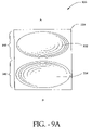
- FIG. 9A is a top view of a lower endplate of a further embodiment of the disclosed implant of the invention.
- FIG. 9B is a top view of an upper endplate of the embodiment of the disclosed implant of the invention depicted in FIG. 9A .
- FIG. 9C is a posterior view of the embodiment of the disclosed implant of the invention depicted in FIGS. 9A and 9B .
- FIG. 10A is a top view of a lower endplate of a further embodiment of the implant of the disclosed invention.
- FIG. 10B is a top view of an upper endplate of the embodiment of the implant of the disclosed invention depicted in FIG. 10A .
- FIG. 10C is an anterior view of the embodiment of the implant of the disclosed invention depicted in FIGS. 10A and 10B .
- FIG. 10D is a posterior view of the embodiment of the implant of the disclosed invention depicted in FIGS. 10A , 10 B, and 10 C.
- FIG. 11 is a block diagram illustrating the steps of a method for inserting the disclosed embodiments of the implant of the invention between two adjacent vertebral bodies. This method can be adapted for lateral, anterior or posterior surgical approaches.
- FIG. 12A is a top view of an embodiment of a cutting tool of the invention used to prepare the vertebral bodies for the implant.
- FIG. 12B is a side view of the embodiment of the cutting tool of the invention.
- FIG. 12C is a distal end view of an embodiment of the cutting tool of the invention.
- FIG. 12D is a top view of the cutting portion of an alternative embodiment of the cutting tool of the invention showing blade protectors.
- FIG. 12E is a side view of the cutting portion of an alternative embodiment of the cutting tool of the invention showing the blade protectors.
- FIG. 13A is a side view of an embodiment of the implant insertion tool of the invention.
- FIG. 13B is a top view of the embodiment of the implant insertion tool of the invention.
- FIG. 13C is a distal end view of the embodiment of the implant insertion tool of the invention.
- FIG. 13D is a top view of an embodiment of the implant insertion tool holding an embodiment of the implant.
- FIGS. 1-4 show an embodiment of the implant 100 of the invention having a two-piece configuration.
- the designations, “A” for anterior, “P” for posterior, “RL” for right lateral, and “LL” for left lateral are given in the drawings for spatial orientation. These designations give the relationship of all faces of embodiments of the disclosed intervertebral implant from the superior perspective; i.e. looking down the axis of the spine.
- the implant 100 has a first endplate, or upper endplate 110 that is configured to mate with a first upper vertebral body.
- the upper endplate 110 of implant 100 has a first exterior surface 112 from which a first keel 114 extends with a first set of teeth 115 .
- the first keel 114 is substantially perpendicular to the median sagittal plane of the spine, in which extension and flexion occur.
- the first keel 114 in this orientation offers substantial stability during extension and flexion for the implant 100 inserted between the vertebrae of a patient.
- the first exterior surface 112 abuts the first vertebral body.
- the first keel 114 extends into the cancellous bone of the upper vertebral body, in which a keel-receiving channel has been cut to receive the first keel 114 , to anchor implant 100 into position.
- the first keel 114 also can have a plurality of apertures 116 through it, to enhance bone ingrowth from the first vertebral body and stabilization of the implant.
- the implant 100 also has a second, or lower, endplate 120 that is configured to mate with a second, lower vertebral body.
- the lower endplate 120 has a second exterior surface 122 from which a keel 124 extends with a second set of teeth 125 .
- the second exterior surface 122 abuts the second vertebral body when the implant 100 is implanted, and the second keel 124 extends into the cancellous bone of the second vertebral body within a keel-receiving channel cut to receive the second keel 124 .
- the second keel 124 thus anchors the implant 100 and stabilizes the spine.
- the second keel 124 extending from the second exterior surface 122 can have a plurality of apertures 116 through the second keel 124 to promote bone ingrowth and further stabilize the anchored implant 100 .
- the second keel 124 like the first keel 114 , is also perpendicular to the median sagittal plane of the spine, in which extension and flexion occur.
- the upper endplate 110 of implant 100 has a first exterior surface 112 from which a first keel 114 extends with a first set of teeth 115 .
- the first keel 114 when implant 100 is inserted between vertebrae, the first keel 114 extends across the first exterior surface 112 , about perpendicular to the sagittal plane of the spine and about perpendicular to the anterior-posterior axis 118 of the implant 100 .
- the first keel 114 extends only partially across the first exterior surface 112 , about perpendicular to the sagittal plane of the spine and the anterior-posterior axis 118 of the implant 100 . It will be appreciated that a plurality of first keels 114 extending from the first exterior surface 112 and oriented along the axis 118 is also contemplated by this disclosure.
- the lower endplate 120 has a second exterior surface 122 from which a keel 124 extends with a second set of teeth 125 .
- the second keel 124 when implant 100 is inserted between vertebrae, the second keel 124 is about perpendicular to the sagittal plane of the spine.
- the second keel 124 extends across the second exterior surface 122
- the second keel 124 extends partially across the second exterior surface 122 . It will be appreciated that a plurality of second keels 124 extending from the second exterior surface 122 is also contemplated by this disclosure.
- the teeth 115 , 125 further serve to anchor the implant and prevent expulsion or displacement after the implant 100 is surgically positioned.
- the teeth 115 , 125 of the keels 114 , 124 point towards the left lateral face of implant 100 when the embodiment is inserted into a keel-receiving channel cut into a vertebral body from the left lateral approach to the spine. This orientation assists in keeping the implant in place as its teeth block backward motion of the implant along the line of implantation. This orientation is shown in the figures, and is particularly evident where the second keel 124 is fully displayed, as in FIG. 2 , for example, which provides an anterior view of implant 100 .
- the teeth 115 , 125 point towards the right lateral face of implant 100 when the embodiments are inserted into a keel-receiving channel cut into a vertebral body from the right lateral approach to the spine.
- the inner surface 126 of the first (upper) endplate 110 and inner surface 127 of the second (lower) endplate 120 oppose each other when the implant 100 is implanted.
- the opposition of the two inner surfaces 126 and 127 aligns two articulating elements 140 , 142 along the antero-posterior axis 118 of the implant 100 to allow flexion and extension of the spine, as well as limited lateral and rotational movement.
- the first articulating element 140 is an anterior articulating element
- the second articulating element 142 is a posterior articulating element.
- Each articulating element 140 , 142 includes two units, with a first unit which can be formed from or connected with one of the inner surfaces 126 , 127 and a second unit which can be formed from or connected with the other of the inner surfaces 126 , 127 .
- the specific configuration of the inner surfaces 126 , 127 of the endplates 110 , 120 of the implant 100 can be as follows.
- the first inner surface 126 of the upper endplate 110 can have a sigmoidal or S-shaped curve that is continuous and smooth all along the curve.
- the S-shape creates contours of the first inner surface 126 .
- the S-shape of the first inner surface 126 creates a first projection 130 and a first depression 128 aligned along an anterior-posterior axis.
- the first depression 128 can be located anteriorly and the first projection 130 can be located posteriorly or, the first depression 128 can be located posteriorly and the first projection 130 can be positioned anteriorly.
- the depression 128 is located anterior and the projection 130 is located posterior to more closely model flexion and extension of the spine. Accordingly, during flexion or forward bending, the anterior articulation element 140 is able to model such forward motion.
- the posterior articulating element 142 can spread apart.
- the posterior articulating element 142 is able to model such backward motion.
- the anterior articulating element 140 can spread apart.
- the exterior edge (either anterior or posterior, depending upon the placement of the depression) of the first depression 128 includes first peak 129 adapted to prevent slippage during movement of the opposing and mating second projection on the second inner surface 127 , discussed in greater detail below.
- the second inner surface 127 also is S-shaped and continuous and smooth along the curve.
- the S-shape of the second inner surface 127 is inverted with respect to the S-shape of the first inner surface 126 , and adapted to mate with the curve of the first inner surface 126 .
- the inverted S-shape likewise bestows contours to the second inner surface 127 .
- the inverted S-shape of the second inner surface 127 creates a second projection 132 and a second depression 134 , aligned next to each other on an anterior-posterior axis 118 .
- the second projection 132 can be positioned anteriorly with the second depression 134 positioned posteriorly, or the second projection 132 can be positioned posteriorly with the second depression 134 located anteriorly.
- An exterior edge (either anterior or posterior, depending upon the placement of the depression) of the second depression 134 includes a peak 135 adapted to prevent slippage during movement of the opposing and mating first projection 130 .
- the two depressions 128 , 134 have peaks 129 , 135 that serve as stops to prevent over-rotation of the two endplates 110 , 120 relative to each other.
- the ligaments and anatomy of the spine further constrain the mobility of the implant.
- the second projection 132 from the second endplate 120 mates with the first depression 128 from the first endplate 110 to permit a smooth rolling motion.
- the mating combination of the second projection 132 with the first depression 128 is a first articulating element 140 .
- the first projection 130 from the first endplate 110 mates with the second depression 134 from the second endplate 120 to permit a smooth rolling motion.
- the mating combination of the first projection 130 and the second depression 134 is a second articulating element 142 .
- the two articulating elements 140 , 142 are joined in continuous smooth fashion in an anterior-posterior plane, so that the endplates 110 , 120 translate motion about a pivot point, which motion creates forward flexion and rearward extension of the spine.
- the smooth surfaces and continuous contours further allow for some lateral and rotational movement of the spine.
- first and second keels 114 , 124 are aligned in the axial plane, perpendicular to the sagittal plane of the vertebrae.
- the first and second keels 114 , 124 extend into the vertebral bodies to anchor implant 100 into position, and are perpendicular to the median sagittal plane of the spine, in which extension and flexion occur.
- the first and second keels 114 , 124 in this orientation offer substantial stability during extension and flexion for implant 100 inserted between the vertebrae of a patient.
- the first and second keels 114 , 124 in this embodiment are aligned with and support the axis of articulation of implant 100 defined by an RL to LL orientation.
- the first and second keels 114 , 124 include apertures 116 that facilitate bone ingrowth.
- bone from the vertebral bodies can grow through the apertures 116 and aid in securing the first and second keels 114 , 124 and thereby also aid in securing implant 100 once inserted between adjacent vertebral bodies.
- surfaces defined by the first and second keels 114 , 124 and the first and second exterior surfaces 112 , 122 of implant 100 can be roughened in order to promote bone ingrowth into these defined surfaces of implant 100 .
- the apertures 116 , the first and second keels 114 , 124 , and the first and second exterior surfaces 112 , 122 of implant 100 can be coated with materials that promote bone growth such as for example bone morphogenic protein, BMP, or structural materials such as hyaluronic acid, HA, or other substance which promotes growth of bone relative to and into the keels 114 , 124 , keel apertures 116 , and other external surfaces of the implant 100 .
- materials that promote bone growth such as for example bone morphogenic protein, BMP, or structural materials such as hyaluronic acid, HA, or other substance which promotes growth of bone relative to and into the keels 114 , 124 , keel apertures 116 , and other external surfaces of the implant 100 .
- the disclosure of the implant of the invention further contemplates treating the exterior surfaces 112 , 122 , including the keels 114 , 124 , to create a porous surface and thereby promote bone ingrowth and fixation.
- One such treatment can be with plasma spray titanium, and another, with a coating of sintered beads.
- the implant 100 can have casted porous surfaces, where the porous surface is integral to the implant 100 .
- the disclosure also contemplates the use of bone screws, as depicted in FIG. 8A or other appropriate bone anchor, to anchor the implant 100 .
- bone screws 225 or anchors can be applied through a bore hole in each of the first and second endplates 210 , 220 and into the vertebral bodies in which the first and second endplates 210 , 220 are embedded.
- the bore hole can be defined by a lip on each of the first endplate 210 and the second end 220 plate.
- the lip 226 wraps partially over each vertebral body and places the bore hold (not shown) over the vertebral body so that the bone screw 225 or other bone anchor can further anchor the implant 200 to the vertebral body.
- Implant 200 is a further embodiment of the invention. Implant 200 is intended for implantation using a posterior surgical approach ( FIGS. 7 , 8 a, e.g.), or postero-lateral surgical approach ( FIG. 8 b, e.g.).
- implant 200 has a first endplate, or upper endplate 210 that is configured to mate with a first vertebra.
- the upper endplate 210 of implant 200 has a first exterior surface 212 from which a first keel 214 extends with a first set of teeth 215 .
- Implant 200 also has a second endplate, or lower endplate 220 that is configured to mate with a second vertebra.
- the lower endplate 220 has a second exterior surface 222 from which a keel 224 extends with a second set of teeth 225 .
- the first exterior surface 212 of the implant 200 When positioned between adjacent vertebrae, the first exterior surface 212 of the implant 200 abuts the vertebral body.
- the first keel 214 extends longitudinally across the first exterior surface 212 , about parallel to the median sagittal plane of the spine, the plane in which extension and flexion occur. This is in contrast to implant 100 , wherein the keel 114 extends across the first exterior surface 112 in a plane that is substantially perpendicular to the sagittal plane of the vertebrae, and parallel to the axial plane of the vertebrae.
- first keel 214 of implant 200 also can extend only partially across the first exterior surface 212 , about parallel to the sagittal plane of the spine. It also will be appreciated that a plurality of keels is further contemplated by this disclosure.
- the keel 214 is received into a keel-receiving channel. If the implantation uses an anterior surgical approach, then the keel-receiving channel is cut into the vertebral body from an anterior approach. If the implantation surgery uses a posterior approach, then the keel-receiving channel is cut from posterior approach. The resulting keel-receiving channel in either surgical approach is parallel to the sagittal plane of the spine.
- the keel-receiving channels would be cut from the left or right lateral side to the opposite side, the keel-receiving channels would perpendicular to the sagittal plane of the spine, and implant 100 should be used.
- Teeth 215 on the keel 214 prevent displacement or expulsion of the implant 200 , and also serve as anchors.
- the teeth 215 on the keel 214 whether the keel 214 extends fully or partially across the first exterior surface 212 of the upper endplate 210 , point anteriorly when the embodiment is to be inserted from an anterior to posterior direction. This orientation is shown in the figures, and is particularly evident where the keel 214 is fully displayed, as in FIGS. 5 and 7 , for example.
- the teeth 215 on the keel 214 point posteriorly when the embodiment is to be inserted from a posterior to anterior direction (see FIG. 8 b ).
- the lower endplate 220 of implant 200 has a second exterior surface 222 from which a keel 224 extends with a second set of teeth 225 .
- exterior surface 222 abuts the lower vertebra.
- the second keel 224 is received into a keel-receiving channel cut into the lower vertebra about parallel to the sagittal plane of the spine.
- the second keel 224 extends longitudinally across the second exterior surface 222 , but it can extend partially, rather than fully.
- a plurality of keels is also contemplated by this disclosure.
- the second set of teeth 225 of the second keel 224 point towards the anterior for this embodiment that is to be implanted from an anterior approach.
- the keel 224 is to be received into a keel-receiving channel cut into a vertebral body from an anterior approach to the spine, and the teeth 215 are intended to prevent displacement. This orientation is shown in the figures, and is particularly evident where the second keel 124 is fully displayed, as in FIG. 5 and 7 , for example.
- the teeth 225 point posteriorly to prevent expulsion of the implant 200 or displacement.
- the keel 224 is received into a keel-receiving channel cut into the lower vertebra from a posterior approach.
- the first and second keels 214 , 224 include apertures 216 to facilitate bone ingrowth.
- surfaces defined by the first and second keels 214 , 224 and the first and second exterior surfaces 212 , 222 of implant 200 also can be roughened in order to promote bone ingrowth into these defined surfaces of implant 200 .
- the apertures 216 , the first and second keels 214 , 224 , and the first and second exterior surfaces 212 , 222 of implant 200 can be coated with materials that promote bone growth.
- the disclosure of the implant of the invention further contemplates treating the exterior surfaces 212 , 222 , including the keels 214 , 224 , to create a porous surface and thereby promote bone ingrowth and fixation.
- One such treatment can be with plasma spray titanium, and another, with a coating of sintered beads.
- the implant 200 can have casted porous surfaces, where the porous surface is integral to the implant 200 .
- the disclosure of the implant of the invention also contemplates the use of bone screws 225 or other appropriate bone anchor as in FIG. 8 a.
- Such bone screws 225 or anchors can be applied through a bore hole in each of the first and second endplates 210 , 220 and into the vertebral bodies in which the first and second endplates 210 , 220 are embedded.
- the bore hole can be defined by a lip on each of the first endplate 210 and the second end 220 plate.
- the lip 226 wraps partially over each vertebral body and places the bore hold (not shown) over the vertebral body so that the bone screw 225 or other bone anchor can further anchor the implant 200 to the vertebral body.
- Each articulating element 240 , 242 includes a projection derived from either the first or second inner surface 226 , 227 , and a depression derived from the other of the first or second inner surface 226 , 227 as described in greater detail below.
- the specific configuration of the articulating elements 240 , 242 can operate essentially as described for the articulating elements 140 , 142 of implant 100 .
- the first inner surface 226 of the upper endplate 210 can have a sigmoidal or S-shaped curve that is continuous and smooth all along the curve.
- the S-shape creates contours of the first inner surface 226 .
- the S-shape of the first inner surface 226 creates a first projection 230 and a first depression 228 aligned in along an anterior-posterior axis.
- the first depression 228 can be located anteriorly and the first projection 230 can be located posteriorly or, the first depression 228 can be located posteriorly and the first projection 230 can be positioned anteriorly.
- the depression 228 is located anterior and the projection 230 is located posterior to more closely model flexion and extension of the spine. Accordingly, during flexion in forward bending, the anterior articulation element 240 is able to model such forward motion.
- the posterior articulating element 242 can spread apart.
- the posterior articulating element 242 is able to model such backward motion.
- the anterior articulating element 240 can spread apart.
- the first depression 228 has an exterior edge (either anterior or posterior, depending upon the placement of the depression) that includes a peak 229 adapted to prevent slippage during movement of the opposing and mating second projection on the second inner surface 227 , discussed in greater detail below.
- the second inner surface 227 also is S-shaped and continuous and smooth along the curve.
- the S-shape of the second inner surface 227 is inverted with respect to the S-shape of the first inner surface 226 , and adapted to mate with the curve of the first inner surface 226 .
- the inverted S-shape likewise bestows contours to the second inner surface 227 .
- the inverted S-shape of the second inner surface 227 creates a second projection 232 and a second depression 234 , aligned next to each other on an anterior-posterior axis 218 .
- the second projection 232 can be positioned anteriorly with the second depression 234 positioned posteriorly, or the second projection 232 can be positioned posteriorly with the second depression 234 located anteriorly.
- the second depression 234 has an exterior edge (either anterior or posterior, depending upon the placement of the depression) that includes a peak 235 adapted to prevent slippage during movement of the opposing and mating first projection 230 .
- the two depressions 228 , 234 have peaks 229 , 235 that serve as stops to prevent over-rotation of the two endplates 210 , 220 relative to each other.
- the ligaments and anatomy of the spine further constrain the mobility of the implant.
- the second projection 232 from the second endplate 220 mates with the first depression 228 from the first endplate 210 to permit a smooth rolling motion.
- the mating combination of the second projection 232 with the first depression 228 is a first articulating element 240 .
- the first projection 230 from the first endplate 210 mates with the second depression 234 from the second endplate 220 to permit a smooth rolling motion.
- the mating combination of the first projection 230 and the second depression 234 is a second articulating element 242 .
- the two articulating elements 240 , 242 are joined in continuous smooth fashion in an anterior-posterior plane, so that the endplates 210 , 220 translate motion about a pivot point, which motion creates forward flexion and rearward extension of the spine.
- the smooth surfaces and continuous contours further allow for some lateral and rotational movement of the spine.
- FIGS. 9A-9C Another embodiment 300 , depicted in FIGS. 9A-9C , has a first exterior surface 312 , second exterior surface 322 , first keel 314 , and second keel 324 substantially similar to the corresponding parts disclosed above for embodiments 100 and 200 . That is, embodiment 300 has a first upper endplate 310 that mates with a first upper vertebral body. The first upper endplate 310 has a first exterior surface 312 from which a first keel 314 extends. First keel 314 has a first set of teeth 315 . The first keel 314 can be substantially perpendicular to the sagittal plate of the spine, where implant 300 is intended and designed to be inserted from a lateral direction. Alternatively, the first keel 314 can be substantially parallel to the sagittal plane of the spine where the implant 300 is intended to be implanted posteriorly or anteriorly.
- the first exterior surface 312 abuts the first vertebral body.
- the first keel 314 extends into the cancellous bone of the upper vertebral body, in which a keel-receiving channel has been cut to receive the first keel 314 , to anchor the implant 300 in position.
- the first keel 314 can have a plurality of apertures 316 (not shown) through it, to enhance bone ingrowth from the first vertebral body and stabilization of the implant 300 .
- the implant 300 also has a second lower endplate 320 , that is configured to mate with a second lower vertebral body.
- the lower endplate 320 has a second exterior surface 322 from which a second keel 324 extends with a second set of teeth 325 .
- the second exterior surface 322 abuts the second vertebral body when the implant 300 is implanted, and the second keel 324 extends into the cancellous bone of the second vertebral body within a keel-receiving channel that is cut to receive the second keel 324 .
- the second keel 324 thus anchors the implant 300 and stabilizes the spine.
- the second keel 324 extending from the second exterior surface 322 can have a plurality of apertures 316 to promote bone ingrowth and further stabilize the anchored implant 300 .
- the second keel 324 like the first keel 314 , is also perpendicular to the median sagittal plane of the spine.
- the second keel 324 can be substantially parallel to the sagittal plane of the spine where the implant 300 is intended to be implanted posteriorly or anteriorly.
- the first keel 314 and second keel 324 when implant 300 is inserted laterally between two vertebral bodies, the first keel 314 and second keel 324 extend fully across the first exterior surfaces 312 , 322 about perpendicular to the sagittal plane of the spine and about perpendicular to the anterior-posterior axis 318 of the implant 300 . In another embodiment, the first keel 314 and second keel 324 extend only partially across the first exterior surface 312 and second exterior surface 322 , about perpendicular to the sagittal plane of the spine and the anterior-posterior axis 318 of the implant 300 .
- first keels 314 extending from the first exterior surface 312
- second keels 324 extending from the second exterior surface 322 and oriented along the axis 118 are also contemplated by this disclosure.
- keels 312 and 324 can be oriented parallel to the sagittal plane of the spine.
- the teeth 315 , 325 further serve to anchor the implant 300 and prevent expulsion or displacement after the implant 300 is surgically positioned.
- the teeth 315 , 325 of the keels 314 , 324 point towards the left lateral face of the implant 300 when the embodiment is inserted into a keel-receiving channel cut into a vertebral body from the left lateral approach to the spine.
- the teeth 315 , 325 point towards the right lateral face of the implant 300 when the embodiment is inserted into a keel-receiving channel cut into a vertebral body from the right lateral approach to the spine.
- embodiment 300 has inner surfaces that differ.
- the projections and depressions are substantially cylindrical which allows for the rolling articulation for extension and flexion. Such arrangements allow for lateral and side-to-side slipping.
- the cylindrical projections and depressions can be curved at the lateral edge in order to enhance lateral or side-to-side slippage.
- the first and second articulating elements 340 , 342 can comprise a ball-and-socket type of interaction by altering somewhat the form of their first and second depressions 328 , 334 and first and second projections 330 , 332 of a substantially hemispherical shape.
- each depression 328 , 334 with a compatible hemispherical projection 330 , 332 should be sufficiently loose to allow for forward-rearward motion that is translated in implant 300 as flexion and extension of the spine.
- Each articulating element 340 , 342 is also sufficiently flexible and loose as to permit rotational and lateral movement of the spine. Free rotational and lateral movement is still restricted by the ligaments associated with the spine. It should be appreciated by one of skill in the art that ball-and-socket type of articulating element need not have hemispherical projections extending from the inner surface but rather, can have any other shape that allows pivoting to occur.
- FIGS. 10A-10D A further embodiment 400 is depicted in FIGS. 10A-10D .
- embodiment 400 like embodiment 300 , has ball-and-socket type first and second articulating elements 440 and 442 aligned along an anterior axis.
- the articulating element 442 has a looser fit than the anterior articulating element 440 . That is, the depression 434 is substantially broader than the second projection 430 that mates with it.
- the anterior articulating element 440 has a relatively tighter fit.
- the depression 428 loosely fits the projection 432 , but not as loosely as the fit of the posterior articulating element 442 .
- This preferred embodiment allows extension and flexion and greater twisting about the anterior articulating element 440 . This configuration can increase flexibility of the spine for flexion and extension, rotational movement, and lateral bending.
- an anterior articulating element 440 that has a looser fit than the posterior articulating element 442 .
- the depression 428 is substantially broader than the projection 432 that mates with it, while the depression 434 of the posterior articulating element 442 has a relatively tighter fit with the projection 430 .
- embodiment 400 has a first exterior surface 412 , second exterior surface 422 , first keel 414 , and second keel 424 . That is, embodiment 400 has a first upper endplate 410 that mates with a first upper vertebral body.
- the first upper endplate 410 has a first exterior surface 412 from which a first keel 414 extends.
- First keel 414 has a first set of teeth 415 .
- the first keel 414 can be substantially perpendicular to the sagittal plate of the spine, where implant 400 is intended and designed to be inserted from a lateral direction. Alternatively, the first keel 414 can be substantially parallel to the sagittal plane of the spine where the implant 400 is intended to be implanted posteriorly or anteriorly.
- the first exterior surface 412 abuts the first vertebral body.
- the first keel 414 extends into the cancellous bone of the upper vertebral body, in which a keel-receiving channel has been cut to receive the first keel 414 , to anchor the implant 400 in position.
- the first keel 414 can have a plurality of apertures 416 through it, to enhance bone ingrowth from the first vertebral body and stabilization of the implant 400 .
- the implant 400 also has a second lower endplate 420 , that is configured to mate with a second lower vertebral body.
- the lower endplate 420 has a second exterior surface 422 from which a second keel 424 extends with a second set of teeth 425 .
- the second exterior surface 422 abuts the second vertebral body when the implant 400 is implanted, and the second keel 424 extends into the cancellous bone of the second vertebral body within a keel-receiving channel that is cut to receive the second keel 424 .
- the second keel 424 thus anchors the implant 400 and stabilizes the spine.
- the second keel 424 extending from the second exterior surface 422 can have a plurality of apertures 416 to promote bone ingrowth and further stabilize the anchored implant 400 .
- the second keel 424 like the first keel 414 , is also perpendicular to the median sagittal plane of the spine.
- the second keel 424 can be substantially parallel to the sagittal plane of the spine where the implant 400 is intended to be implanted postero- or antero- laterally.
- the first keel 414 and second keel 424 when implant 400 is inserted laterally between two vertebral bodies, the first keel 414 and second keel 424 extend fully across the first exterior surfaces 412 , 422 about perpendicular to the sagittal plane of the spine and about perpendicular to the anterior-posterior axis 418 of the implant 400 . In another embodiment, the first keel 414 and second keel 424 extend only partially across the first exterior surface 412 and second exterior surface 422 , about perpendicular to the sagittal plane of the spine and the antero-posterior axis 418 of the implant 400 .
- first keels 414 extending from the first exterior surface 412
- second keels 424 extending from the second exterior surface 422 and oriented along the axis 418 are also contemplated by this disclosure.
- keels 412 and 424 can be oriented parallel to the sagittal plane of the spine.
- the teeth 415 , 425 further serve to anchor the implant 400 and prevent expulsion or displacement after the implant 400 is surgically positioned.
- the teeth 415 , 425 of the keels 414 , 424 point towards the left lateral face of the implant 400 when the embodiment is inserted into a keel-receiving channel cut into a vertebral body from the left lateral approach to the spine.
- the teeth 415 , 425 point towards the right lateral face of the implant 400 when the embodiment is inserted into a keel-receiving channel cut into a vertebral body from the right lateral approach to the spine.
- any of the implants disclosed above can be made of medical grade titanium, stainless steel, or cobalt chrome. Other materials that have appropriate structural strength and that are suitable for implantation into a patient can also be used.
- a copolymer is a polymer derived from more than one species of monomer.
- a polymer composite is a heterogeneous combination of two or more materials, wherein the constituents are not miscible, and therefore exhibit an interface between one another.
- a polymer blend is a macroscopically homogeneous mixture of two or more different species of polymer.
- biocompatible polymers are the polyaryl ester ketones which has several members, which include polyetheretherketone (PEEK), and polyetherketoneketone (PEKK).
- PEEK has proven as a durable material for implants, as well as meeting criteria of biocompatibility.
- Medical grade PEEK is available from Victrex Corporation under the product name PEEK-OPTIMA.
- Medical grade PEKK is available from Oxford Performance Materials under the name OXPEKK, and also from CoorsTek under the name BioPEKK.
- Still another interesting group of biocompatible polymers are polyalkyl biocompatible polymers, such as polyethylenes, polypropylenes, and the like.
- These medical grade biocompatible polymers are also available as reinforced polymer materials.
- fillers are added to a polymer, copolymer, polymer blend, or polymer composite. Fillers are added to modify properties, such as mechanical, optical, and thermal properties. In this case, fillers, such as carbon fibers, are added to reinforce the polymers mechanically to enhance strength for certain uses, such as load bearing devices.
- FIG. 11 is a block diagram showing the basic steps of the method for laterally inserting the implant 100 .
- the spine is exposed through a lateral access 510 , and distracted if necessary 515 .
- the intervertebral disk is removed 520 , if necessary.
- the affected vertebrae are distracted, if necessary 520 .
- a tool such as the one disclosed in application Ser. No. 10/685,134 of James F. Zucherman et al., filed Oct.
- FIG. 12A depicts a top view of a cutting tool 700 used to prepare the vertebral bodies for the implant 100 and FIG. 12B depicts a side view of tool 700 .
- the cutting tool 700 has a handle 710 at its proximal end for controlling the tool during operation. As will be appreciated by those of skill in the art, the handle 710 can be removable or affixed to the cutting end.
- the distal end 702 of the tool 700 is forked to form two prongs or tines 705 , 706 .
- the end of each tine 705 , 706 has a beveled edge 716 at its distal most end.
- Each tine 705 , 706 also has an inner blade 712 located on an inner upper side and an outer blade 714 located on an outer lower side (shown in FIG. 12C ).
- the inner blades 712 are coplanar with the surface of the inner side of the tine and the outer blades 714 are coplanar with the outer side of the tine.
- the inner blades 712 are oriented to cut a space in a first intervertebral body for the first surface keel 116 of the implant and the outer blades 714 are oriented to cut a space in the facing intervertebral body for the second surface keel 126 .
- the orientation of the blades is such that each of the cuts made for the keels of the implant are offset and avoid the nerves in the cauda equina or exiting the cauda equina.
- FIG. 12C is a view of the distal end of the cutting tool 700 showing the beveled edges 716 of the tines 705 , 706 and the inner blades 712 and outer blades 714 .
- the distance 722 between the inner blades 712 is less than the distance 724 between the outer blades and the height h of the tines approximates the distance between two vertebral bodies or the height of the disk space.
- the blades 712 , 714 extend above and below the tines or the height of the tines.
- the beveled sides of the distal end 716 extend and form at least one of the beveled sides of the blades 712 , 714 .
- FIG. 12D depicts an enlarged top view of the tines 705 , 706 of the distal end of cutting tool 700 with the beveled distal edges 716 .
- FIG. 12E is an enlarged side view of the distal end of cutting tool 700 .
- FIGS. 12D and 12E show the retractable blade protector 720 for the blade 712 positioned in a retracted position. As the cutting tool is inserted between vertebral bodies, the retractable blade protector 720 moves in a posterior direction 715 (i.e., toward the handle 710 ) to expose the inner blade 712 and the outer blade 714 and to enable the blades to cut into the vertebral bodies.
- protectors 720 can be spring biased as desired in order to cover the blade 712 , 714 as the tool 700 is inserted past the nerves.
- the protectors 720 are urged in a posterior direction as the blades 712 , 714 are urged into the vertebral bodies in order to cut channels for the keels.
- Springs 721 provide the desired bias to keep the protectors 720 in a forward position covering the blades 712 , 718 .
- the tool shown in FIG. 12 can be modified such that instead of cutting keel-receiving channels in the upper and lower vertebral bodies at the same time, two tools are provided so that only one vertebral body is cut for keel-receiving channels at a time.
- a first tool having two tines as described above could be provided having a pair of inner blades located on an upper surface of the tines.
- a second tool could be provided having tines as described with a pair of outer blades located on the lower surface of the tines.
- the second tool can have a guide corresponding to the location of the first blade on the first tool to ensure that the second cut is optimally aligned with the first cut.
- a pair of channels can be cut into the upper vertebral body using the first tool. Thereafter a second pair of channels can be cut into the lower vertebral body.
- first tool has a pair of outer blades and the second tool has a pair of inner blades, or where the first tool has upper and lower blades on a first tine (e.g., right tine) and the second tool has upper and lower blades on a second tine (e.g., left tine).
- the keel-receiving channels are oriented perpendicular to the sagittal plane of the spine.
- the implant is then inserted laterally 530 between two vertebrae, with the keels aligned and inserted into the keel-receiving channels.
- a tool similar to the one disclosed in application Ser. No. 10/685,134 of James F. Zucherman et al., filed Oct. 14, 2003, and entitled, “Tools for Implanting an Artificial Vertebral Disk and Method,” incorporated herein by reference, can be used to position the implant in the intervertebral disk space 535 .
- FIG. 13A depicts the implanting tool used to insert an implant between vertebral bodies.
- FIG. 13A is a side view of the implantation tool 800 that has a handle 810 and an implant holder 820 .
- the implant holder 820 has an implant conforming surface 824 and two pins 822 for holding a first plate 110 and a second plate 120 of a first half of the implant.
- the implant nests within a conforming surface 824 and is held by pins 822 .
- FIG. 13C shows the distal view of the end of the tool with two pins 822 , 823 for securing the first and second plate of the implant.
- the tool can be rotated by the user 180° to implant the other half of the implant.
- kits can be assembled that include an implant sized for a particular patient.
- the kit could also include several cutting tools 700 and several implanting tools 800 or a single handle that cooperates with cutting ends 702 and implantation ends 820 .
- the implant also can be anchored with bone screws if necessary 540 . After implantation, the wound is closed 545 . This procedure can be followed for either a left lateral approach or right lateral approach.
- the disclosed method further can be used for an anterior or posterior approach to insert implant 200 or any implant wherein the keels are oriented substantially parallel to the sagittal plane of the spine.
- the access step 510 would involve making an incision anteriorly. Keel-receiving channels are cut from an anterior direction to receive first and second keels that are substantially parallel to the sagittal plane of the spine.
- the implant 200 (or other appropriate implant, as indicated) would be inserted from an anterior approach to align the first and second keels 214 , 224 with the keel-receiving channels in the adjacent vertebral bodies.
- the teeth 215 , 225 of the first and second keels 214 , 224 would face anteriorly.
- the access step 510 would involve making an incision posteriorly.
- the keels 214 , 224 would be cut from the posterior of the spine, to create keel-receiving channels that are substantially parallel to the sagittal plane of the vertebrae.
- the implant 200 would be inserted from a posterior approach to align the keels 214 , 224 with the keel-receiving channels in the adjacent vertebral bodies.
- the teeth 215 , 225 of the upper and lower keels 214 , 224 would face posteriorly.
Abstract
Description
Claims (17)
Priority Applications (1)
| Application Number | Priority Date | Filing Date | Title |
|---|---|---|---|
| US11/003,624 US7575600B2 (en) | 2004-09-29 | 2004-12-03 | Artificial vertebral disk replacement implant with translating articulation contact surface and method |
Applications Claiming Priority (2)
| Application Number | Priority Date | Filing Date | Title |
|---|---|---|---|
| US61430204P | 2004-09-29 | 2004-09-29 | |
| US11/003,624 US7575600B2 (en) | 2004-09-29 | 2004-12-03 | Artificial vertebral disk replacement implant with translating articulation contact surface and method |
Publications (2)
| Publication Number | Publication Date |
|---|---|
| US20060069439A1 US20060069439A1 (en) | 2006-03-30 |
| US7575600B2 true US7575600B2 (en) | 2009-08-18 |
Family
ID=36100292
Family Applications (1)
| Application Number | Title | Priority Date | Filing Date |
|---|---|---|---|
| US11/003,624 Expired - Fee Related US7575600B2 (en) | 2004-09-29 | 2004-12-03 | Artificial vertebral disk replacement implant with translating articulation contact surface and method |
Country Status (1)
| Country | Link |
|---|---|
| US (1) | US7575600B2 (en) |
Cited By (54)
| Publication number | Priority date | Publication date | Assignee | Title |
|---|---|---|---|---|
| US20050033435A1 (en) * | 2003-08-04 | 2005-02-10 | Spine Next | Intervertebral disk prosthesis |
| US20080058939A1 (en) * | 2006-08-25 | 2008-03-06 | Warsaw Orthopedic, Inc. | Revision Spacer |
| US20090131986A1 (en) * | 2007-11-19 | 2009-05-21 | David Lee | Method and apparatus for spinal facet joint fusion using irregularly shaped cortical bone implants |
| US20100094422A1 (en) * | 2008-10-13 | 2010-04-15 | Noah Hansell | Intervertebral Spacer |
| US20100106190A1 (en) * | 2008-10-23 | 2010-04-29 | Linares Medical Devices, Llc | Support insert associated with spinal vertebrae |
| US8012207B2 (en) | 2004-10-20 | 2011-09-06 | Vertiflex, Inc. | Systems and methods for posterior dynamic stabilization of the spine |
| US8123782B2 (en) | 2004-10-20 | 2012-02-28 | Vertiflex, Inc. | Interspinous spacer |
| US8123807B2 (en) | 2004-10-20 | 2012-02-28 | Vertiflex, Inc. | Systems and methods for posterior dynamic stabilization of the spine |
| US20120053693A1 (en) * | 2004-04-28 | 2012-03-01 | Ldr Medical | Intervertebral disc prosthesis |
| US8128662B2 (en) | 2004-10-20 | 2012-03-06 | Vertiflex, Inc. | Minimally invasive tooling for delivery of interspinous spacer |
| US8152837B2 (en) | 2004-10-20 | 2012-04-10 | The Board Of Trustees Of The Leland Stanford Junior University | Systems and methods for posterior dynamic stabilization of the spine |
| US8167944B2 (en) | 2004-10-20 | 2012-05-01 | The Board Of Trustees Of The Leland Stanford Junior University | Systems and methods for posterior dynamic stabilization of the spine |
| US8273108B2 (en) | 2004-10-20 | 2012-09-25 | Vertiflex, Inc. | Interspinous spacer |
| US8277488B2 (en) | 2004-10-20 | 2012-10-02 | Vertiflex, Inc. | Interspinous spacer |
| US8292922B2 (en) | 2004-10-20 | 2012-10-23 | Vertiflex, Inc. | Interspinous spacer |
| US8317864B2 (en) | 2004-10-20 | 2012-11-27 | The Board Of Trustees Of The Leland Stanford Junior University | Systems and methods for posterior dynamic stabilization of the spine |
| US8409282B2 (en) | 2004-10-20 | 2013-04-02 | Vertiflex, Inc. | Systems and methods for posterior dynamic stabilization of the spine |
| US8425559B2 (en) | 2004-10-20 | 2013-04-23 | Vertiflex, Inc. | Systems and methods for posterior dynamic stabilization of the spine |
| US8613747B2 (en) | 2004-10-20 | 2013-12-24 | Vertiflex, Inc. | Spacer insertion instrument |
| US8628574B2 (en) | 2004-10-20 | 2014-01-14 | Vertiflex, Inc. | Systems and methods for posterior dynamic stabilization of the spine |
| US8685100B2 (en) | 2007-02-16 | 2014-04-01 | Ldr Medical | Interveterbral disc prosthesis insertion assemblies |
| US8740948B2 (en) | 2009-12-15 | 2014-06-03 | Vertiflex, Inc. | Spinal spacer for cervical and other vertebra, and associated systems and methods |
| US8753397B2 (en) | 2002-11-05 | 2014-06-17 | Ldr Medical | Intervertebral disc prosthesis |
| US8771284B2 (en) | 2005-11-30 | 2014-07-08 | Ldr Medical | Intervertebral disc prosthesis and instrumentation for insertion of the prosthesis between the vertebrae |
| US8808377B2 (en) | 2010-01-13 | 2014-08-19 | Jcbd, Llc | Sacroiliac joint fixation system |
| US8845726B2 (en) | 2006-10-18 | 2014-09-30 | Vertiflex, Inc. | Dilator |
| US8858635B2 (en) | 2004-02-04 | 2014-10-14 | Ldr Medical | Intervertebral disc prosthesis |
| US8864828B2 (en) | 2004-10-20 | 2014-10-21 | Vertiflex, Inc. | Interspinous spacer |
| US8945183B2 (en) | 2004-10-20 | 2015-02-03 | Vertiflex, Inc. | Interspinous process spacer instrument system with deployment indicator |
| US8979932B2 (en) | 2005-09-23 | 2015-03-17 | Ldr Medical | Intervertebral disc prosthesis |
| US9023084B2 (en) | 2004-10-20 | 2015-05-05 | The Board Of Trustees Of The Leland Stanford Junior University | Systems and methods for stabilizing the motion or adjusting the position of the spine |
| US9119680B2 (en) | 2004-10-20 | 2015-09-01 | Vertiflex, Inc. | Interspinous spacer |
| US9161783B2 (en) | 2004-10-20 | 2015-10-20 | Vertiflex, Inc. | Interspinous spacer |
| US9259327B2 (en) | 2008-10-13 | 2016-02-16 | Globus Medical, Inc. | Articulating spacer |
| US9333090B2 (en) | 2010-01-13 | 2016-05-10 | Jcbd, Llc | Systems for and methods of fusing a sacroiliac joint |
| US9358122B2 (en) | 2011-01-07 | 2016-06-07 | K2M, Inc. | Interbody spacer |
| US9381045B2 (en) | 2010-01-13 | 2016-07-05 | Jcbd, Llc | Sacroiliac joint implant and sacroiliac joint instrument for fusing a sacroiliac joint |
| US9393055B2 (en) | 2004-10-20 | 2016-07-19 | Vertiflex, Inc. | Spacer insertion instrument |
| US9421109B2 (en) | 2010-01-13 | 2016-08-23 | Jcbd, Llc | Systems and methods of fusing a sacroiliac joint |
| US20160270928A1 (en) * | 2015-03-18 | 2016-09-22 | Baui Biotech Co., Ltd. | Spinal spacer |
| US9510872B2 (en) | 2013-03-15 | 2016-12-06 | Jcbd, Llc | Spinal stabilization system |
| US9526634B2 (en) | 2005-05-27 | 2016-12-27 | Spinecore, Inc. | Intervertebral disc and insertion methods therefor |
| US9554909B2 (en) | 2012-07-20 | 2017-01-31 | Jcbd, Llc | Orthopedic anchoring system and methods |
| US9675303B2 (en) | 2013-03-15 | 2017-06-13 | Vertiflex, Inc. | Visualization systems, instruments and methods of using the same in spinal decompression procedures |
| US9700356B2 (en) | 2013-07-30 | 2017-07-11 | Jcbd, Llc | Systems for and methods of fusing a sacroiliac joint |
| US9717539B2 (en) | 2013-07-30 | 2017-08-01 | Jcbd, Llc | Implants, systems, and methods for fusing a sacroiliac joint |
| US9788961B2 (en) | 2010-01-13 | 2017-10-17 | Jcbd, Llc | Sacroiliac joint implant system |
| US9801546B2 (en) | 2014-05-27 | 2017-10-31 | Jcbd, Llc | Systems for and methods of diagnosing and treating a sacroiliac joint disorder |
| US9826986B2 (en) | 2013-07-30 | 2017-11-28 | Jcbd, Llc | Systems for and methods of preparing a sacroiliac joint for fusion |
| US10245087B2 (en) | 2013-03-15 | 2019-04-02 | Jcbd, Llc | Systems and methods for fusing a sacroiliac joint and anchoring an orthopedic appliance |
| US10441322B2 (en) | 2016-05-13 | 2019-10-15 | Musc Foundation For Research Development | Anterior spinal implants for reducing spinal malalignment and associated systems and methods |
| US10524772B2 (en) | 2014-05-07 | 2020-01-07 | Vertiflex, Inc. | Spinal nerve decompression systems, dilation systems, and methods of using the same |
| US10603185B2 (en) | 2004-02-04 | 2020-03-31 | Ldr Medical | Intervertebral disc prosthesis |
| US10603055B2 (en) | 2017-09-15 | 2020-03-31 | Jcbd, Llc | Systems for and methods of preparing and fusing a sacroiliac joint |
Families Citing this family (58)
| Publication number | Priority date | Publication date | Assignee | Title |
|---|---|---|---|---|
| US7494507B2 (en) * | 2000-01-30 | 2009-02-24 | Diamicron, Inc. | Articulating diamond-surfaced spinal implants |
| US20080027548A9 (en) * | 2002-04-12 | 2008-01-31 | Ferree Bret A | Spacerless artificial disc replacements |
| US8038713B2 (en) | 2002-04-23 | 2011-10-18 | Spinecore, Inc. | Two-component artificial disc replacements |
| US6706068B2 (en) | 2002-04-23 | 2004-03-16 | Bret A. Ferree | Artificial disc replacements with natural kinematics |
| EP2002805A3 (en) * | 2002-09-19 | 2009-01-07 | Malan De Villiers | Intervertebral prosthesis |
| WO2004066884A1 (en) | 2003-01-31 | 2004-08-12 | Spinalmotion, Inc. | Intervertebral prosthesis placement instrument |
| EP2329778A3 (en) * | 2003-01-31 | 2012-06-20 | Spinalmotion, Inc. | Spinal midline indicator |
| AU2004212942A1 (en) | 2003-02-14 | 2004-09-02 | Depuy Spine, Inc. | In-situ formed intervertebral fusion device |
| US6908484B2 (en) | 2003-03-06 | 2005-06-21 | Spinecore, Inc. | Cervical disc replacement |
| WO2004105638A2 (en) | 2003-05-27 | 2004-12-09 | Spinalmotion, Inc. | Prosthetic disc for intervertebral insertion |
| US20090076614A1 (en) * | 2007-09-17 | 2009-03-19 | Spinalmotion, Inc. | Intervertebral Prosthetic Disc with Shock Absorption Core |
| US7575599B2 (en) | 2004-07-30 | 2009-08-18 | Spinalmotion, Inc. | Intervertebral prosthetic disc with metallic core |
| US10052211B2 (en) | 2003-05-27 | 2018-08-21 | Simplify Medical Pty Ltd. | Prosthetic disc for intervertebral insertion |
| US7585326B2 (en) | 2004-08-06 | 2009-09-08 | Spinalmotion, Inc. | Methods and apparatus for intervertebral disc prosthesis insertion |
| US8083797B2 (en) | 2005-02-04 | 2011-12-27 | Spinalmotion, Inc. | Intervertebral prosthetic disc with shock absorption |
| US8366773B2 (en) | 2005-08-16 | 2013-02-05 | Benvenue Medical, Inc. | Apparatus and method for treating bone |
| AU2006279558B2 (en) | 2005-08-16 | 2012-05-17 | Izi Medical Products, Llc | Spinal tissue distraction devices |
| US8454617B2 (en) | 2005-08-16 | 2013-06-04 | Benvenue Medical, Inc. | Devices for treating the spine |
| US8734519B2 (en) * | 2006-04-12 | 2014-05-27 | Spinalmotion, Inc. | Posterior spinal device and method |
| US20080161923A1 (en) * | 2006-09-28 | 2008-07-03 | Matthew Parsons | Intervertebral Motion Disc Having A Resorbable Keel |
| US8105382B2 (en) | 2006-12-07 | 2012-01-31 | Interventional Spine, Inc. | Intervertebral implant |
| ES2905157T3 (en) | 2007-02-09 | 2022-04-07 | Dimicron Inc | Multilobe Spine Joint |
| EP2124777A4 (en) * | 2007-02-21 | 2013-06-05 | Benvenue Medical Inc | Devices for treating the spine |
| US8900307B2 (en) | 2007-06-26 | 2014-12-02 | DePuy Synthes Products, LLC | Highly lordosed fusion cage |
| US20090043391A1 (en) | 2007-08-09 | 2009-02-12 | Spinalmotion, Inc. | Customized Intervertebral Prosthetic Disc with Shock Absorption |
| US8758441B2 (en) | 2007-10-22 | 2014-06-24 | Spinalmotion, Inc. | Vertebral body replacement and method for spanning a space formed upon removal of a vertebral body |
| CN101909548B (en) | 2008-01-17 | 2014-07-30 | 斯恩蒂斯有限公司 | An expandable intervertebral implant and associated method of manufacturing the same |
| US8764833B2 (en) * | 2008-03-11 | 2014-07-01 | Spinalmotion, Inc. | Artificial intervertebral disc with lower height |
| WO2009124269A1 (en) | 2008-04-05 | 2009-10-08 | Synthes Usa, Llc | Expandable intervertebral implant |
| US9034038B2 (en) | 2008-04-11 | 2015-05-19 | Spinalmotion, Inc. | Motion limiting insert for an artificial intervertebral disc |
| KR20110009216A (en) | 2008-05-05 | 2011-01-27 | 스피날모우션, 인코포레이티드 | Polyaryletherketone artificial intervertebral disc |
| US9220603B2 (en) * | 2008-07-02 | 2015-12-29 | Simplify Medical, Inc. | Limited motion prosthetic intervertebral disc |
| EP2299944A4 (en) | 2008-07-17 | 2013-07-31 | Spinalmotion Inc | Artificial intervertebral disc placement system |
| EP2299941A1 (en) * | 2008-07-18 | 2011-03-30 | Spinalmotion Inc. | Posterior prosthetic intervertebral disc |
| US8535327B2 (en) | 2009-03-17 | 2013-09-17 | Benvenue Medical, Inc. | Delivery apparatus for use with implantable medical devices |
| US9526620B2 (en) | 2009-03-30 | 2016-12-27 | DePuy Synthes Products, Inc. | Zero profile spinal fusion cage |
| US8211178B2 (en) | 2009-06-18 | 2012-07-03 | Warsaw Orthopedic | Intervertebral implant with a pivoting end cap |
| US9393129B2 (en) | 2009-12-10 | 2016-07-19 | DePuy Synthes Products, Inc. | Bellows-like expandable interbody fusion cage |
| US8979860B2 (en) | 2010-06-24 | 2015-03-17 | DePuy Synthes Products. LLC | Enhanced cage insertion device |
| US9907560B2 (en) | 2010-06-24 | 2018-03-06 | DePuy Synthes Products, Inc. | Flexible vertebral body shavers |
| TW201215379A (en) | 2010-06-29 | 2012-04-16 | Synthes Gmbh | Distractible intervertebral implant |
| US9402732B2 (en) | 2010-10-11 | 2016-08-02 | DePuy Synthes Products, Inc. | Expandable interspinous process spacer implant |
| WO2012178018A2 (en) | 2011-06-24 | 2012-12-27 | Benvenue Medical, Inc. | Devices and methods for treating bone tissue |
| US9522070B2 (en) | 2013-03-07 | 2016-12-20 | Interventional Spine, Inc. | Intervertebral implant |
| US10085783B2 (en) | 2013-03-14 | 2018-10-02 | Izi Medical Products, Llc | Devices and methods for treating bone tissue |
| US11426290B2 (en) | 2015-03-06 | 2022-08-30 | DePuy Synthes Products, Inc. | Expandable intervertebral implant, system, kit and method |
| JP7019616B2 (en) | 2016-06-28 | 2022-02-15 | イーアイティー・エマージング・インプラント・テクノロジーズ・ゲーエムベーハー | Expandable and angle adjustable intervertebral cage with range of motion joints |
| JP6995789B2 (en) | 2016-06-28 | 2022-01-17 | イーアイティー・エマージング・インプラント・テクノロジーズ・ゲーエムベーハー | Expandable and angle adjustable intervertebral cage |
| US10888433B2 (en) | 2016-12-14 | 2021-01-12 | DePuy Synthes Products, Inc. | Intervertebral implant inserter and related methods |
| US10398563B2 (en) | 2017-05-08 | 2019-09-03 | Medos International Sarl | Expandable cage |
| US11344424B2 (en) | 2017-06-14 | 2022-05-31 | Medos International Sarl | Expandable intervertebral implant and related methods |
| US10940016B2 (en) | 2017-07-05 | 2021-03-09 | Medos International Sarl | Expandable intervertebral fusion cage |
| CN107753160B (en) * | 2017-11-16 | 2023-08-25 | 天津正天医疗器械有限公司 | Mortise and tenon type artificial vertebral body |
| US11446156B2 (en) | 2018-10-25 | 2022-09-20 | Medos International Sarl | Expandable intervertebral implant, inserter instrument, and related methods |
| US11452618B2 (en) | 2019-09-23 | 2022-09-27 | Dimicron, Inc | Spinal artificial disc removal tool |
| US11426286B2 (en) | 2020-03-06 | 2022-08-30 | Eit Emerging Implant Technologies Gmbh | Expandable intervertebral implant |
| US11850160B2 (en) | 2021-03-26 | 2023-12-26 | Medos International Sarl | Expandable lordotic intervertebral fusion cage |
| US11752009B2 (en) | 2021-04-06 | 2023-09-12 | Medos International Sarl | Expandable intervertebral fusion cage |
Citations (94)
| Publication number | Priority date | Publication date | Assignee | Title |
|---|---|---|---|---|
| US243286A (en) | 1881-06-21 | Charles mowilltam | ||
| US572486A (en) | 1896-12-01 | Gustav horn | ||
| US2261446A (en) | 1939-12-07 | 1941-11-04 | Theodore A Ormsby | Charge former |
| US2456806A (en) | 1947-01-14 | 1948-12-21 | Erwin B Wolffe | Vaginal gauge |
| US2677369A (en) | 1952-03-26 | 1954-05-04 | Fred L Knowles | Apparatus for treatment of the spinal column |
| US2804936A (en) | 1953-07-18 | 1957-09-03 | Drager Otto H | Dust filters |
| US3320951A (en) | 1964-04-21 | 1967-05-23 | Wittebol Paul | Intramedullary prostheses |
| US3426364A (en) | 1966-08-25 | 1969-02-11 | Colorado State Univ Research F | Prosthetic appliance for replacing one or more natural vertebrae |
| US3510883A (en) | 1967-10-30 | 1970-05-12 | Robert F Cathcart | Joint prosthesis |
| US3648691A (en) | 1970-02-24 | 1972-03-14 | Univ Colorado State Res Found | Method of applying vertebral appliance |
| US3740769A (en) | 1971-02-11 | 1973-06-26 | E Haboush | Prosthesis for hip joints |
| US3867728A (en) | 1971-12-30 | 1975-02-25 | Cutter Lab | Prosthesis for spinal repair |
| US3875595A (en) | 1974-04-15 | 1975-04-08 | Edward C Froning | Intervertebral disc prosthesis and instruments for locating same |
| US3903549A (en) | 1974-06-12 | 1975-09-09 | William Minor Deyerle | Acetabular cup prosthesis component for total or subtotal hip prosthesis system |
| US4309777A (en) | 1980-11-13 | 1982-01-12 | Patil Arun A | Artificial intervertebral disc |
| US4349921A (en) | 1980-06-13 | 1982-09-21 | Kuntz J David | Intervertebral disc prosthesis |
| US4369769A (en) | 1980-06-13 | 1983-01-25 | Edwards Charles C | Spinal fixation device and method |
| US4401112A (en) | 1980-09-15 | 1983-08-30 | Rezaian Seyed M | Spinal fixator |
| US4470158A (en) | 1978-03-10 | 1984-09-11 | Biomedical Engineering Corp. | Joint endoprosthesis |
| US4479491A (en) | 1982-07-26 | 1984-10-30 | Martin Felix M | Intervertebral stabilization implant |
| US4499613A (en) | 1983-03-01 | 1985-02-19 | Yarrow Harry A | Ankle joint and coupling for artificial limbs |
| US4501269A (en) | 1981-12-11 | 1985-02-26 | Washington State University Research Foundation, Inc. | Process for fusing bone joints |
| US4550450A (en) | 1984-07-24 | 1985-11-05 | Kinnett James G | Total shoulder prosthesis system |
| US4553273A (en) | 1983-11-23 | 1985-11-19 | Henry Ford Hospital | Vertebral body prosthesis and spine stabilizing method |
| US4554914A (en) | 1983-10-04 | 1985-11-26 | Kapp John P | Prosthetic vertebral body |
| US4599084A (en) | 1983-05-24 | 1986-07-08 | American Hospital Supply Corp. | Method of using biological tissue to promote even bone growth |
| US4599086A (en) | 1985-06-07 | 1986-07-08 | Doty James R | Spine stabilization device and method |
| US4622959A (en) | 1985-03-05 | 1986-11-18 | Marcus Randall E | Multi-use femoral intramedullary nail |
| US4636217A (en) | 1985-04-23 | 1987-01-13 | Regents Of The University Of Minnesota | Anterior spinal implant |
| US4653487A (en) | 1986-01-29 | 1987-03-31 | Maale Gerhard E | Intramedullary rod assembly for cement injection system |
| US4657550A (en) | 1984-12-21 | 1987-04-14 | Daher Youssef H | Buttressing device usable in a vertebral prosthesis |
| US4681589A (en) | 1984-06-01 | 1987-07-21 | Tronzo Raymond G | Adjustable acetabular cup prosthesis as part of a total cup replacement system |
| US4685447A (en) | 1985-03-25 | 1987-08-11 | Pmt Corporation | Tissue expander system |
| US4696290A (en) | 1983-12-16 | 1987-09-29 | Acromed Corporation | Apparatus for straightening spinal columns |
| US4714469A (en) | 1987-02-26 | 1987-12-22 | Pfizer Hospital Products Group, Inc. | Spinal implant |
| US4743256A (en) | 1985-10-04 | 1988-05-10 | Brantigan John W | Surgical prosthetic implant facilitating vertebral interbody fusion and method |
| US4759769A (en) | 1987-02-12 | 1988-07-26 | Health & Research Services Inc. | Artificial spinal disc |
| US4759766A (en) | 1984-09-04 | 1988-07-26 | Humboldt-Universitaet Zu Berlin | Intervertebral disc endoprosthesis |
| US4772287A (en) | 1987-08-20 | 1988-09-20 | Cedar Surgical, Inc. | Prosthetic disc and method of implanting |
| US4790303A (en) | 1987-03-11 | 1988-12-13 | Acromed Corporation | Apparatus and method for securing bone graft |
| US4805607A (en) | 1987-12-03 | 1989-02-21 | Boehringer Mannheim Corporation | Modular intramedullary nail system |
| US4834757A (en) | 1987-01-22 | 1989-05-30 | Brantigan John W | Prosthetic implant |
| US4863477A (en) | 1987-05-12 | 1989-09-05 | Monson Gary L | Synthetic intervertebral disc prosthesis |
| US4874389A (en) | 1987-12-07 | 1989-10-17 | Downey Ernest L | Replacement disc |
| US4875474A (en) | 1988-01-29 | 1989-10-24 | Biomet, Inc. | Variable wall thickness interlocking intramedullary nail |
| US4892545A (en) | 1988-07-14 | 1990-01-09 | Ohio Medical Instrument Company, Inc. | Vertebral lock |
| US4904261A (en) | 1987-08-06 | 1990-02-27 | A. W. Showell (Surgicraft) Limited | Spinal implants |
| US4911718A (en) | 1988-06-10 | 1990-03-27 | University Of Medicine & Dentistry Of N.J. | Functional and biocompatible intervertebral disc spacer |
| US4932969A (en) | 1987-01-08 | 1990-06-12 | Sulzer Brothers Limited | Joint endoprosthesis |
| US4932975A (en) | 1989-10-16 | 1990-06-12 | Vanderbilt University | Vertebral prosthesis |
| US4936848A (en) | 1989-09-22 | 1990-06-26 | Bagby George W | Implant for vertebrae |
| US4946378A (en) | 1987-11-24 | 1990-08-07 | Asahi Kogaku Kogyo Kabushiki Kaisha | Artificial intervertebral disc |
| US4961740A (en) | 1988-10-17 | 1990-10-09 | Surgical Dynamics, Inc. | V-thread fusion cage and method of fusing a bone joint |
| US4969888A (en) | 1989-02-09 | 1990-11-13 | Arie Scholten | Surgical protocol for fixation of osteoporotic bone using inflatable device |
| US4997432A (en) | 1988-03-23 | 1991-03-05 | Waldemar Link Gmbh & Co. | Surgical instrument set |
| US5002576A (en) | 1988-06-06 | 1991-03-26 | Mecron Medizinische Produkte Gmbh | Intervertebral disk endoprosthesis |
| US5004476A (en) | 1989-10-31 | 1991-04-02 | Tulane University | Porous coated total hip replacement system |
| US5011484A (en) | 1987-11-16 | 1991-04-30 | Breard Francis H | Surgical implant for restricting the relative movement of vertebrae |
| US5015247A (en) | 1988-06-13 | 1991-05-14 | Michelson Gary K | Threaded spinal implant |
| US5037438A (en) | 1989-07-25 | 1991-08-06 | Richards Medical Company | Zirconium oxide coated prosthesis for wear and corrosion resistance |
| US5047055A (en) | 1990-12-21 | 1991-09-10 | Pfizer Hospital Products Group, Inc. | Hydrogel intervertebral disc nucleus |
| US5055104A (en) | 1989-11-06 | 1991-10-08 | Surgical Dynamics, Inc. | Surgically implanting threaded fusion cages between adjacent low-back vertebrae by an anterior approach |
| US5059194A (en) | 1990-02-12 | 1991-10-22 | Michelson Gary K | Cervical distractor |
| US5059193A (en) | 1989-11-20 | 1991-10-22 | Spine-Tech, Inc. | Expandable spinal implant and surgical method |
| US5062850A (en) | 1990-01-16 | 1991-11-05 | University Of Florida | Axially-fixed vertebral body prosthesis and method of fixation |
| US5071437A (en) | 1989-02-15 | 1991-12-10 | Acromed Corporation | Artificial disc |
| US5102954A (en) | 1990-11-09 | 1992-04-07 | Baukema Paul R | Low formaldehyde polyacetal containing coating |
| US5108442A (en) | 1991-05-09 | 1992-04-28 | Boehringer Mannheim Corporation | Prosthetic implant locking assembly |
| US5108438A (en) | 1989-03-02 | 1992-04-28 | Regen Corporation | Prosthetic intervertebral disc |
| US5108395A (en) | 1989-09-18 | 1992-04-28 | Societe De Fabrication De Materiel Orthopedique - Sofamor | Implant for anterior dorsolumbar spinal osteosynthesis, intended for the correction of kyphoses |
| US5123926A (en) | 1991-02-22 | 1992-06-23 | Madhavan Pisharodi | Artificial spinal prosthesis |
| US5167662A (en) | 1992-01-24 | 1992-12-01 | Zimmer, Inc. | Temporary clamp and inserter for a posterior midline spinal clamp |
| US5171281A (en) | 1988-08-18 | 1992-12-15 | University Of Medicine & Dentistry Of New Jersey | Functional and biocompatible intervertebral disc spacer containing elastomeric material of varying hardness |
| US5171280A (en) | 1990-04-20 | 1992-12-15 | Sulzer Brothers Limited | Intervertebral prosthesis |
| US5180381A (en) | 1991-09-24 | 1993-01-19 | Aust Gilbert M | Anterior lumbar/cervical bicortical compression plate |
| US5192327A (en) | 1991-03-22 | 1993-03-09 | Brantigan John W | Surgical prosthetic implant for vertebrae |
| US5192326A (en) | 1990-12-21 | 1993-03-09 | Pfizer Hospital Products Group, Inc. | Hydrogel bead intervertebral disc nucleus |
| US5246458A (en) | 1992-10-07 | 1993-09-21 | Graham Donald V | Artificial disk |
| US5258043A (en) | 1987-07-20 | 1993-11-02 | Regen Corporation | Method for making a prosthetic intervertebral disc |
| US5258031A (en) | 1992-01-06 | 1993-11-02 | Danek Medical | Intervertebral disk arthroplasty |
| US5263953A (en) | 1991-12-31 | 1993-11-23 | Spine-Tech, Inc. | Apparatus and system for fusing bone joints |
| US5271737A (en) | 1992-09-04 | 1993-12-21 | U.S. Medical Products, Inc. | Tibial prosthetic implant with offset stem |
| US5282868A (en) | 1991-06-17 | 1994-02-01 | Andre Bahler | Prosthetic arrangement for a complex joint, especially knee joint |
| US5290312A (en) | 1991-09-03 | 1994-03-01 | Alphatec | Artificial vertebral body |
| US5306308A (en) | 1989-10-23 | 1994-04-26 | Ulrich Gross | Intervertebral implant |
| US5306307A (en) | 1991-07-22 | 1994-04-26 | Calcitek, Inc. | Spinal disk implant |
| US5306309A (en) | 1992-05-04 | 1994-04-26 | Calcitek, Inc. | Spinal disk implant and implantation kit |
| US5306275A (en) | 1992-12-31 | 1994-04-26 | Bryan Donald W | Lumbar spine fixation apparatus and method |
| US5313962A (en) | 1991-10-18 | 1994-05-24 | Obenchain Theodore G | Method of performing laparoscopic lumbar discectomy |
| US5314478A (en) | 1991-03-29 | 1994-05-24 | Kyocera Corporation | Artificial bone connection prosthesis |
| US5314477A (en) | 1990-03-07 | 1994-05-24 | J.B.S. Limited Company | Prosthesis for intervertebral discs and instruments for implanting it |
| US5320644A (en) | 1991-08-30 | 1994-06-14 | Sulzer Brothers Limited | Intervertebral disk prosthesis |
| US5336223A (en) | 1993-02-04 | 1994-08-09 | Rogers Charles L | Telescoping spinal fixator |
| US6610093B1 (en) * | 2000-07-28 | 2003-08-26 | Perumala Corporation | Method and apparatus for stabilizing adjacent vertebrae |
Family Cites Families (66)
| Publication number | Priority date | Publication date | Assignee | Title |
|---|---|---|---|---|
| US641706A (en) * | 1899-02-27 | 1900-01-23 | Goetze & Co E | Pastil-press. |
| US5593409A (en) * | 1988-06-13 | 1997-01-14 | Sofamor Danek Group, Inc. | Interbody spinal fusion implants |
| US5484437A (en) * | 1988-06-13 | 1996-01-16 | Michelson; Gary K. | Apparatus and method of inserting spinal implants |
| US5609635A (en) * | 1988-06-28 | 1997-03-11 | Michelson; Gary K. | Lordotic interbody spinal fusion implants |
| US5458638A (en) * | 1989-07-06 | 1995-10-17 | Spine-Tech, Inc. | Non-threaded spinal implant |
| US5390683A (en) * | 1991-02-22 | 1995-02-21 | Pisharodi; Madhavan | Spinal implantation methods utilizing a middle expandable implant |
| US5603713A (en) * | 1991-09-24 | 1997-02-18 | Aust; Gilbert M. | Anterior lumbar/cervical bicortical compression plate |
| US5395317A (en) * | 1991-10-30 | 1995-03-07 | Smith & Nephew Dyonics, Inc. | Unilateral biportal percutaneous surgical procedure |
| GB9125798D0 (en) * | 1991-12-04 | 1992-02-05 | Customflex Limited | Improvements in or relating to spinal vertebrae implants |
| US5509934A (en) * | 1992-02-28 | 1996-04-23 | Osteonics Corp. | Prosthetic knee tibial component constructed of synthetic polymeric material |
| DE4208116C2 (en) * | 1992-03-13 | 1995-08-03 | Link Waldemar Gmbh Co | Intervertebral disc prosthesis |
| FR2693364B1 (en) * | 1992-07-07 | 1995-06-30 | Erpios Snc | INTERVERTEBRAL PROSTHESIS FOR STABILIZING ROTATORY AND FLEXIBLE-EXTENSION CONSTRAINTS. |
| US5383884A (en) * | 1992-12-04 | 1995-01-24 | American Biomed, Inc. | Spinal disc surgical instrument |
| CA2155422C (en) * | 1993-02-10 | 2005-07-12 | Stephen D. Kuslich | Spinal stabilization surgical method |
| FR2701650B1 (en) * | 1993-02-17 | 1995-05-24 | Psi | Double shock absorber for intervertebral stabilization. |
| DE4417629B4 (en) * | 1993-06-24 | 2006-03-16 | SDGI Holdings, Inc., Wilmington | Implant for the replacement of vertebral bodies |
| US5395372A (en) * | 1993-09-07 | 1995-03-07 | Danek Medical, Inc. | Spinal strut graft holding staple |
| BE1007549A3 (en) * | 1993-09-21 | 1995-08-01 | Beckers Louis Francois Charles | Implant. |
| CN1156255C (en) * | 1993-10-01 | 2004-07-07 | 美商-艾克罗米德公司 | Spinal implant |
| US5397364A (en) * | 1993-10-12 | 1995-03-14 | Danek Medical, Inc. | Anterior interbody fusion device |
| US5620458A (en) * | 1994-03-16 | 1997-04-15 | United States Surgical Corporation | Surgical instruments useful for endoscopic spinal procedures |
| CA2144211C (en) * | 1994-03-16 | 2005-05-24 | David T. Green | Surgical instruments useful for endoscopic spinal procedures |
| US6093207A (en) * | 1994-03-18 | 2000-07-25 | Pisharodi; Madhavan | Middle expanded, removable intervertebral disk stabilizer disk |
| JP3509103B2 (en) * | 1994-05-23 | 2004-03-22 | スルザー スパイン−テック インコーポレイテッド | Intervertebral fusion implant |
| US5885299A (en) * | 1994-09-15 | 1999-03-23 | Surgical Dynamics, Inc. | Apparatus and method for implant insertion |
| US5674296A (en) * | 1994-11-14 | 1997-10-07 | Spinal Dynamics Corporation | Human spinal disc prosthesis |
| US5609638A (en) * | 1994-11-29 | 1997-03-11 | Zimmer, Inc. | Reinforced polyethylene for articular surfaces |
| US5860973A (en) * | 1995-02-27 | 1999-01-19 | Michelson; Gary Karlin | Translateral spinal implant |
| US5591235A (en) * | 1995-03-15 | 1997-01-07 | Kuslich; Stephen D. | Spinal fixation device |
| US6206922B1 (en) * | 1995-03-27 | 2001-03-27 | Sdgi Holdings, Inc. | Methods and instruments for interbody fusion |
| US5888222A (en) * | 1995-10-16 | 1999-03-30 | Sdgi Holding, Inc. | Intervertebral spacers |
| KR100415064B1 (en) * | 1995-10-20 | 2005-04-06 | 신테스 아게 츄어 | Intervertebral implant |
| US5709683A (en) * | 1995-12-19 | 1998-01-20 | Spine-Tech, Inc. | Interbody bone implant having conjoining stabilization features for bony fusion |
| US5865845A (en) * | 1996-03-05 | 1999-02-02 | Thalgott; John S. | Prosthetic intervertebral disc |
| US5741261A (en) * | 1996-06-25 | 1998-04-21 | Sdgi Holdings, Inc. | Minimally invasive spinal surgical methods and instruments |
| WO1998009586A1 (en) * | 1996-09-04 | 1998-03-12 | Synthes Ag Chur | Intervertebral implant |
| US5716416A (en) * | 1996-09-10 | 1998-02-10 | Lin; Chih-I | Artificial intervertebral disk and method for implanting the same |
| US6019793A (en) * | 1996-10-21 | 2000-02-01 | Synthes | Surgical prosthetic device |
| US6190414B1 (en) * | 1996-10-31 | 2001-02-20 | Surgical Dynamics Inc. | Apparatus for fusion of adjacent bone structures |
| US6514256B2 (en) * | 1997-01-02 | 2003-02-04 | St. Francis Medical Technologies, Inc. | Spine distraction implant and method |
| US6068630A (en) * | 1997-01-02 | 2000-05-30 | St. Francis Medical Technologies, Inc. | Spine distraction implant |
| US5860977A (en) * | 1997-01-02 | 1999-01-19 | Saint Francis Medical Technologies, Llc | Spine distraction implant and method |
| US6039761A (en) * | 1997-02-12 | 2000-03-21 | Li Medical Technologies, Inc. | Intervertebral spacer and tool and method for emplacement thereof |
| US6641614B1 (en) * | 1997-05-01 | 2003-11-04 | Spinal Concepts, Inc. | Multi-variable-height fusion device |
| US6042582A (en) * | 1997-05-20 | 2000-03-28 | Ray; Charles D. | Instrumentation and method for facilitating insertion of spinal implant |
| US6022376A (en) * | 1997-06-06 | 2000-02-08 | Raymedica, Inc. | Percutaneous prosthetic spinal disc nucleus and method of manufacture |
| US6139579A (en) * | 1997-10-31 | 2000-10-31 | Depuy Motech Acromed, Inc. | Spinal disc |
| US5888226A (en) * | 1997-11-12 | 1999-03-30 | Rogozinski; Chaim | Intervertebral prosthetic disc |
| DE19807236C2 (en) * | 1998-02-20 | 2000-06-21 | Biedermann Motech Gmbh | Intervertebral implant |
| US6019792A (en) * | 1998-04-23 | 2000-02-01 | Cauthen Research Group, Inc. | Articulating spinal implant |
| US6179874B1 (en) * | 1998-04-23 | 2001-01-30 | Cauthen Research Group, Inc. | Articulating spinal implant |
| US6039763A (en) * | 1998-10-27 | 2000-03-21 | Disc Replacement Technologies, Inc. | Articulating spinal disc prosthesis |
| US6193757B1 (en) * | 1998-10-29 | 2001-02-27 | Sdgi Holdings, Inc. | Expandable intervertebral spacers |
| FR2787016B1 (en) * | 1998-12-11 | 2001-03-02 | Dimso Sa | INTERVERTEBRAL DISK PROSTHESIS |
| US6530933B1 (en) * | 1998-12-31 | 2003-03-11 | Teresa T. Yeung | Methods and devices for fastening bulging or herniated intervertebral discs |
| US6342074B1 (en) * | 1999-04-30 | 2002-01-29 | Nathan S. Simpson | Anterior lumbar interbody fusion implant and method for fusing adjacent vertebrae |
| US6520996B1 (en) * | 1999-06-04 | 2003-02-18 | Depuy Acromed, Incorporated | Orthopedic implant |
| US6277149B1 (en) * | 1999-06-08 | 2001-08-21 | Osteotech, Inc. | Ramp-shaped intervertebral implant |
| US6527773B1 (en) * | 1999-10-07 | 2003-03-04 | Osteotech, Inc. | Cervical dowel and insertion tool |
| US6447512B1 (en) * | 2000-01-06 | 2002-09-10 | Spinal Concepts, Inc. | Instrument and method for implanting an interbody fusion device |
| FR2805733B1 (en) * | 2000-03-03 | 2002-06-07 | Scient X | DISC PROSTHESIS FOR CERVICAL VERTEBRUS |
| FR2805985B1 (en) * | 2000-03-10 | 2003-02-07 | Eurosurgical | INTERVERTEBRAL DISK PROSTHESIS |
| US6350283B1 (en) * | 2000-04-19 | 2002-02-26 | Gary K. Michelson | Bone hemi-lumbar interbody spinal implant having an asymmetrical leading end and method of installation thereof |
| US6520993B2 (en) * | 2000-12-29 | 2003-02-18 | Depuy Acromed, Inc. | Spinal implant |
| US6527806B2 (en) * | 2001-07-16 | 2003-03-04 | Third Millennium Engineering, Llc | Intervertebral spacer device having a spiral wave washer force restoring element |
| US6706068B2 (en) * | 2002-04-23 | 2004-03-16 | Bret A. Ferree | Artificial disc replacements with natural kinematics |
-
2004
- 2004-12-03 US US11/003,624 patent/US7575600B2/en not_active Expired - Fee Related
Patent Citations (102)
| Publication number | Priority date | Publication date | Assignee | Title |
|---|---|---|---|---|
| US243286A (en) | 1881-06-21 | Charles mowilltam | ||
| US572486A (en) | 1896-12-01 | Gustav horn | ||
| US2261446A (en) | 1939-12-07 | 1941-11-04 | Theodore A Ormsby | Charge former |
| US2456806A (en) | 1947-01-14 | 1948-12-21 | Erwin B Wolffe | Vaginal gauge |
| US2677369A (en) | 1952-03-26 | 1954-05-04 | Fred L Knowles | Apparatus for treatment of the spinal column |
| US2804936A (en) | 1953-07-18 | 1957-09-03 | Drager Otto H | Dust filters |
| US3320951A (en) | 1964-04-21 | 1967-05-23 | Wittebol Paul | Intramedullary prostheses |
| US3426364A (en) | 1966-08-25 | 1969-02-11 | Colorado State Univ Research F | Prosthetic appliance for replacing one or more natural vertebrae |
| US3510883A (en) | 1967-10-30 | 1970-05-12 | Robert F Cathcart | Joint prosthesis |
| US3648691A (en) | 1970-02-24 | 1972-03-14 | Univ Colorado State Res Found | Method of applying vertebral appliance |
| US3740769A (en) | 1971-02-11 | 1973-06-26 | E Haboush | Prosthesis for hip joints |
| US3867728A (en) | 1971-12-30 | 1975-02-25 | Cutter Lab | Prosthesis for spinal repair |
| US3875595A (en) | 1974-04-15 | 1975-04-08 | Edward C Froning | Intervertebral disc prosthesis and instruments for locating same |
| US3903549A (en) | 1974-06-12 | 1975-09-09 | William Minor Deyerle | Acetabular cup prosthesis component for total or subtotal hip prosthesis system |
| US4470158A (en) | 1978-03-10 | 1984-09-11 | Biomedical Engineering Corp. | Joint endoprosthesis |
| US4349921A (en) | 1980-06-13 | 1982-09-21 | Kuntz J David | Intervertebral disc prosthesis |
| US4369769A (en) | 1980-06-13 | 1983-01-25 | Edwards Charles C | Spinal fixation device and method |
| US4401112A (en) | 1980-09-15 | 1983-08-30 | Rezaian Seyed M | Spinal fixator |
| US4309777A (en) | 1980-11-13 | 1982-01-12 | Patil Arun A | Artificial intervertebral disc |
| US4501269A (en) | 1981-12-11 | 1985-02-26 | Washington State University Research Foundation, Inc. | Process for fusing bone joints |
| US4479491A (en) | 1982-07-26 | 1984-10-30 | Martin Felix M | Intervertebral stabilization implant |
| US4499613A (en) | 1983-03-01 | 1985-02-19 | Yarrow Harry A | Ankle joint and coupling for artificial limbs |
| US4599084A (en) | 1983-05-24 | 1986-07-08 | American Hospital Supply Corp. | Method of using biological tissue to promote even bone growth |
| US4554914A (en) | 1983-10-04 | 1985-11-26 | Kapp John P | Prosthetic vertebral body |
| US4553273A (en) | 1983-11-23 | 1985-11-19 | Henry Ford Hospital | Vertebral body prosthesis and spine stabilizing method |
| US4696290A (en) | 1983-12-16 | 1987-09-29 | Acromed Corporation | Apparatus for straightening spinal columns |
| US4743262A (en) | 1984-06-01 | 1988-05-10 | Tronzo Raymond G | Acetabular cup prosthesis |
| US4743262B1 (en) | 1984-06-01 | 1994-05-17 | Raymond G Tronzo | Acetabular cup prosthesis |
| US4681589A (en) | 1984-06-01 | 1987-07-21 | Tronzo Raymond G | Adjustable acetabular cup prosthesis as part of a total cup replacement system |
| US4550450A (en) | 1984-07-24 | 1985-11-05 | Kinnett James G | Total shoulder prosthesis system |
| US4759766A (en) | 1984-09-04 | 1988-07-26 | Humboldt-Universitaet Zu Berlin | Intervertebral disc endoprosthesis |
| US4657550A (en) | 1984-12-21 | 1987-04-14 | Daher Youssef H | Buttressing device usable in a vertebral prosthesis |
| US4622959A (en) | 1985-03-05 | 1986-11-18 | Marcus Randall E | Multi-use femoral intramedullary nail |
| US4685447A (en) | 1985-03-25 | 1987-08-11 | Pmt Corporation | Tissue expander system |
| US4636217A (en) | 1985-04-23 | 1987-01-13 | Regents Of The University Of Minnesota | Anterior spinal implant |
| US4599086A (en) | 1985-06-07 | 1986-07-08 | Doty James R | Spine stabilization device and method |
| US4743256A (en) | 1985-10-04 | 1988-05-10 | Brantigan John W | Surgical prosthetic implant facilitating vertebral interbody fusion and method |
| US4653487A (en) | 1986-01-29 | 1987-03-31 | Maale Gerhard E | Intramedullary rod assembly for cement injection system |
| US4932969A (en) | 1987-01-08 | 1990-06-12 | Sulzer Brothers Limited | Joint endoprosthesis |
| US4834757A (en) | 1987-01-22 | 1989-05-30 | Brantigan John W | Prosthetic implant |
| US4878915A (en) | 1987-01-22 | 1989-11-07 | Brantigan John W | Surgical prosthetic implant facilitating vertebral interbody fusion |
| US4759769A (en) | 1987-02-12 | 1988-07-26 | Health & Research Services Inc. | Artificial spinal disc |
| US4714469A (en) | 1987-02-26 | 1987-12-22 | Pfizer Hospital Products Group, Inc. | Spinal implant |
| US4790303A (en) | 1987-03-11 | 1988-12-13 | Acromed Corporation | Apparatus and method for securing bone graft |
| US4863477A (en) | 1987-05-12 | 1989-09-05 | Monson Gary L | Synthetic intervertebral disc prosthesis |
| US5258043A (en) | 1987-07-20 | 1993-11-02 | Regen Corporation | Method for making a prosthetic intervertebral disc |
| US4904261A (en) | 1987-08-06 | 1990-02-27 | A. W. Showell (Surgicraft) Limited | Spinal implants |
| US4904260A (en) | 1987-08-20 | 1990-02-27 | Cedar Surgical, Inc. | Prosthetic disc containing therapeutic material |
| US4772287A (en) | 1987-08-20 | 1988-09-20 | Cedar Surgical, Inc. | Prosthetic disc and method of implanting |
| US5011484A (en) | 1987-11-16 | 1991-04-30 | Breard Francis H | Surgical implant for restricting the relative movement of vertebrae |
| US4946378A (en) | 1987-11-24 | 1990-08-07 | Asahi Kogaku Kogyo Kabushiki Kaisha | Artificial intervertebral disc |
| US4805607A (en) | 1987-12-03 | 1989-02-21 | Boehringer Mannheim Corporation | Modular intramedullary nail system |
| US5035716A (en) | 1987-12-07 | 1991-07-30 | Downey Ernest L | Replacement disc |
| US4874389A (en) | 1987-12-07 | 1989-10-17 | Downey Ernest L | Replacement disc |
| US4875474A (en) | 1988-01-29 | 1989-10-24 | Biomet, Inc. | Variable wall thickness interlocking intramedullary nail |
| US5122130A (en) | 1988-03-23 | 1992-06-16 | Waldemar Link Gmbh & Co. | Forceps for inserting intervertebral device |
| US4997432A (en) | 1988-03-23 | 1991-03-05 | Waldemar Link Gmbh & Co. | Surgical instrument set |
| US5002576A (en) | 1988-06-06 | 1991-03-26 | Mecron Medizinische Produkte Gmbh | Intervertebral disk endoprosthesis |
| US4911718A (en) | 1988-06-10 | 1990-03-27 | University Of Medicine & Dentistry Of N.J. | Functional and biocompatible intervertebral disc spacer |
| US5015247A (en) | 1988-06-13 | 1991-05-14 | Michelson Gary K | Threaded spinal implant |
| US4892545A (en) | 1988-07-14 | 1990-01-09 | Ohio Medical Instrument Company, Inc. | Vertebral lock |
| US5171281A (en) | 1988-08-18 | 1992-12-15 | University Of Medicine & Dentistry Of New Jersey | Functional and biocompatible intervertebral disc spacer containing elastomeric material of varying hardness |
| US4961740B1 (en) | 1988-10-17 | 1997-01-14 | Surgical Dynamics Inc | V-thread fusion cage and method of fusing a bone joint |
| US5026373A (en) | 1988-10-17 | 1991-06-25 | Surgical Dynamics, Inc. | Surgical method and apparatus for fusing adjacent bone structures |
| US4961740A (en) | 1988-10-17 | 1990-10-09 | Surgical Dynamics, Inc. | V-thread fusion cage and method of fusing a bone joint |
| US4969888A (en) | 1989-02-09 | 1990-11-13 | Arie Scholten | Surgical protocol for fixation of osteoporotic bone using inflatable device |
| US5071437A (en) | 1989-02-15 | 1991-12-10 | Acromed Corporation | Artificial disc |
| US5108438A (en) | 1989-03-02 | 1992-04-28 | Regen Corporation | Prosthetic intervertebral disc |
| US5037438A (en) | 1989-07-25 | 1991-08-06 | Richards Medical Company | Zirconium oxide coated prosthesis for wear and corrosion resistance |
| US5108395A (en) | 1989-09-18 | 1992-04-28 | Societe De Fabrication De Materiel Orthopedique - Sofamor | Implant for anterior dorsolumbar spinal osteosynthesis, intended for the correction of kyphoses |
| US4936848A (en) | 1989-09-22 | 1990-06-26 | Bagby George W | Implant for vertebrae |
| US4932975A (en) | 1989-10-16 | 1990-06-12 | Vanderbilt University | Vertebral prosthesis |
| US5306308A (en) | 1989-10-23 | 1994-04-26 | Ulrich Gross | Intervertebral implant |
| US5004476A (en) | 1989-10-31 | 1991-04-02 | Tulane University | Porous coated total hip replacement system |
| US5055104A (en) | 1989-11-06 | 1991-10-08 | Surgical Dynamics, Inc. | Surgically implanting threaded fusion cages between adjacent low-back vertebrae by an anterior approach |
| US5059193A (en) | 1989-11-20 | 1991-10-22 | Spine-Tech, Inc. | Expandable spinal implant and surgical method |
| US5062850A (en) | 1990-01-16 | 1991-11-05 | University Of Florida | Axially-fixed vertebral body prosthesis and method of fixation |
| US5059194A (en) | 1990-02-12 | 1991-10-22 | Michelson Gary K | Cervical distractor |
| US5314477A (en) | 1990-03-07 | 1994-05-24 | J.B.S. Limited Company | Prosthesis for intervertebral discs and instruments for implanting it |
| US5171280A (en) | 1990-04-20 | 1992-12-15 | Sulzer Brothers Limited | Intervertebral prosthesis |
| US5102954A (en) | 1990-11-09 | 1992-04-07 | Baukema Paul R | Low formaldehyde polyacetal containing coating |
| US5047055A (en) | 1990-12-21 | 1991-09-10 | Pfizer Hospital Products Group, Inc. | Hydrogel intervertebral disc nucleus |
| US5192326A (en) | 1990-12-21 | 1993-03-09 | Pfizer Hospital Products Group, Inc. | Hydrogel bead intervertebral disc nucleus |
| US5123926A (en) | 1991-02-22 | 1992-06-23 | Madhavan Pisharodi | Artificial spinal prosthesis |
| US5192327A (en) | 1991-03-22 | 1993-03-09 | Brantigan John W | Surgical prosthetic implant for vertebrae |
| US5314478A (en) | 1991-03-29 | 1994-05-24 | Kyocera Corporation | Artificial bone connection prosthesis |
| US5108442A (en) | 1991-05-09 | 1992-04-28 | Boehringer Mannheim Corporation | Prosthetic implant locking assembly |
| US5282868A (en) | 1991-06-17 | 1994-02-01 | Andre Bahler | Prosthetic arrangement for a complex joint, especially knee joint |
| US5306307A (en) | 1991-07-22 | 1994-04-26 | Calcitek, Inc. | Spinal disk implant |
| US5320644A (en) | 1991-08-30 | 1994-06-14 | Sulzer Brothers Limited | Intervertebral disk prosthesis |
| US5290312A (en) | 1991-09-03 | 1994-03-01 | Alphatec | Artificial vertebral body |
| US5180381A (en) | 1991-09-24 | 1993-01-19 | Aust Gilbert M | Anterior lumbar/cervical bicortical compression plate |
| US5313962A (en) | 1991-10-18 | 1994-05-24 | Obenchain Theodore G | Method of performing laparoscopic lumbar discectomy |
| US5263953A (en) | 1991-12-31 | 1993-11-23 | Spine-Tech, Inc. | Apparatus and system for fusing bone joints |
| US5258031A (en) | 1992-01-06 | 1993-11-02 | Danek Medical | Intervertebral disk arthroplasty |
| US5167662A (en) | 1992-01-24 | 1992-12-01 | Zimmer, Inc. | Temporary clamp and inserter for a posterior midline spinal clamp |
| US5306309A (en) | 1992-05-04 | 1994-04-26 | Calcitek, Inc. | Spinal disk implant and implantation kit |
| US5271737A (en) | 1992-09-04 | 1993-12-21 | U.S. Medical Products, Inc. | Tibial prosthetic implant with offset stem |
| US5246458A (en) | 1992-10-07 | 1993-09-21 | Graham Donald V | Artificial disk |
| US5306275A (en) | 1992-12-31 | 1994-04-26 | Bryan Donald W | Lumbar spine fixation apparatus and method |
| US5336223A (en) | 1993-02-04 | 1994-08-09 | Rogers Charles L | Telescoping spinal fixator |
| US6610093B1 (en) * | 2000-07-28 | 2003-08-26 | Perumala Corporation | Method and apparatus for stabilizing adjacent vertebrae |
Non-Patent Citations (20)
| Title |
|---|
| A.H. Crenshaw, Cambell's Operative Orthopedics, Seventh Edition, vol. Two, The C.V. Mosby Company, copyright, 1987. |
| AB Swanson, GD Swanson, T Powers, MA Khalil, BK Maupin, DE Mayhew and SH Moss, The Journal of Bone & Joint Surgery: Unicompartmental and bicompartmental arthroplasty of the knee with a finned metal tibial-plateau implant, vol. 67-A, No. 8, October. |
| Ceramic Interspinous Block (CISB) Assisted Anterior Interbody Fusion, Haruo Tsuji, Norikazu Hirano, Yoshiharu Katoh, Hiroshi Ohsima, Hirokazu Ishihara, Hisao Matsui,and Yohihiko Hayashi, Journal of Spinal Disorders vol. 3. No. 1, pp. 77-86, c1990 Raven Press, Ltd., New York. |
| David S. Hungerford, M.D., and Robert V. Kenna, Preliminary Experience with a Total Knee Prothesis with Porous Coating Used Without Cement, J.B. Lippincott, Co., No. 176, Jun. 1983, pp. 95-107. |
| David S. Hungerford, M.D., Kenneth A. Krackow, M.D., Robert V. Kenna, Total Knee Arthoplasty: A Comprehensive Approach, Williams & Williams, Baltimore, MD., 1984, Chapter 5, pp. 71-88. |
| Grosse, English translation of FR 2742653. |
| Instrumentation and Implants for Spinal Surgery,J. Dabb, Diary of the XVIIIth Scientific Meeting of the PTO Tr/Pamietnik XVIII Zjazdu Naukowego PTO Tr/PZ, WL, Warszawa, Link America Inc., 1971, 665. |
| Jeanette E. Ahrens, PhD, Alexis P. Shelokov, MD, Jeffrey L. Carver, BS, Normal Joint Mobility is Maintained with an Artifical Disc Prothesis, Texas Health Research Institute, Plano, Texas, HCA Columbia Hospital, Plano, Texas, Joint Biomedical Engineering Program. |
| Medtronic Sofamor Dane, "Maverick Total Disc Replacement", brochure, published Dec. 2002, pp. 1-6. |
| Nobou, English translation of JP 2261446. |
| Patent Cooperation Treaty-European Patent Office, "Notification of Transmittal of the International Search Report and the Written Opinion of the International Searching Authority or the Declaration,"International Application No. PC/US2005015581, Aug. 25, 2005. 7. |
| Preliminary Design and Experimental Studies of a Novel Soft Implant for Correcting Sagittal Plan Instability in the Lumbar Spine, R.J.Minns, BEng, Msc, PhD, DscTech, and W.K.Walsh, FRCS, Spine vol. 22, No. 16, pp. 1819-1827, c1997, Lippincott-Raven Publishers. |
| Spinal Stenosis and Neurogenic Claudication, Richard W. Porter, MD, FRCS, FRCSE, Spine vol. 21, No. 17, pp. 2046-2052, c1996, Lippincott-Raven Publishers. |
| T. Hoogland, A. D. Steffe, J.D. Black, A.S. Greenwald, Cleveland Clinic Foundation, 24 Annual ORS Dallas, Texas, Feb. 21-23, 1978. |
| T.Hoggland et al, "Total Lumbar Intervertebral Disc Replacement : Testing of a New Articulating Spacer in Human Cadaver Spines," 24th Annual ORS, Feb. 21-23, 1978, p. 102, Dallas, Texas. |
| TH Marnay, English translation of "L'Arthoplatie Intervertebral Lombaire.", Kennedy Clinic, 30000 Nimes. |
| TH Marnay, L'Arthoplatie Intervertebral Lombaire, Orthopedic Sugeon, Kennedy Clinic, 30000 Nimes. |
| The Journal of Bone and Joint Surgery, Jul. 1970, American Volume, vol. 52-A, No. 5, Zimmer, Warsaw, Indiana, U.S.A., Zimmer of Canada, Ltd. |
| The Journal of Bone and Joint Surgery, Sep. 1971, American Volume, vol. 53-A, No. 6, Zimmer, Warsaw, Indiana, U.S.A., Zimmer of Canada, Ltd. |
| Viscoglioski Bro., LLC, Spine Arthoplasty: Market Potential & Technology Update, Spine Industry Analysis Series, Nov. 2001, pp. 1-215. |
Cited By (121)
| Publication number | Priority date | Publication date | Assignee | Title |
|---|---|---|---|---|
| US8753397B2 (en) | 2002-11-05 | 2014-06-17 | Ldr Medical | Intervertebral disc prosthesis |
| US7611538B2 (en) * | 2003-08-04 | 2009-11-03 | Zimmer Spine S.A.S. | Intervertebral disk prosthesis |
| US7896919B2 (en) | 2003-08-04 | 2011-03-01 | Zimmer Spine S.A.S. | Method of implanting intervertebral disk prosthesis |
| US20110160863A1 (en) * | 2003-08-04 | 2011-06-30 | Karl Belliard | Method of Implanting Intervertebral Disk Prosthesis |
| US20050033435A1 (en) * | 2003-08-04 | 2005-02-10 | Spine Next | Intervertebral disk prosthesis |
| US8226721B2 (en) * | 2003-08-04 | 2012-07-24 | Zimmer Spine S.A.S. | Method of implanting intervertebral disk prosthesis |
| US10603185B2 (en) | 2004-02-04 | 2020-03-31 | Ldr Medical | Intervertebral disc prosthesis |
| US8858635B2 (en) | 2004-02-04 | 2014-10-14 | Ldr Medical | Intervertebral disc prosthesis |
| US20120053693A1 (en) * | 2004-04-28 | 2012-03-01 | Ldr Medical | Intervertebral disc prosthesis |
| US8974532B2 (en) * | 2004-04-28 | 2015-03-10 | Ldr Medical | Intervertebral disc prosthesis |
| US10610267B2 (en) | 2004-10-20 | 2020-04-07 | Vertiflex, Inc. | Spacer insertion instrument |
| US9211146B2 (en) | 2004-10-20 | 2015-12-15 | The Board Of Trustees Of The Leland Stanford Junior University | Systems and methods for posterior dynamic stabilization of the spine |
| US8123782B2 (en) | 2004-10-20 | 2012-02-28 | Vertiflex, Inc. | Interspinous spacer |
| US8128662B2 (en) | 2004-10-20 | 2012-03-06 | Vertiflex, Inc. | Minimally invasive tooling for delivery of interspinous spacer |
| US11076893B2 (en) | 2004-10-20 | 2021-08-03 | Vertiflex, Inc. | Methods for treating a patient's spine |
| US8152837B2 (en) | 2004-10-20 | 2012-04-10 | The Board Of Trustees Of The Leland Stanford Junior University | Systems and methods for posterior dynamic stabilization of the spine |
| US8167944B2 (en) | 2004-10-20 | 2012-05-01 | The Board Of Trustees Of The Leland Stanford Junior University | Systems and methods for posterior dynamic stabilization of the spine |
| US9572603B2 (en) | 2004-10-20 | 2017-02-21 | Vertiflex, Inc. | Interspinous spacer |
| US8273108B2 (en) | 2004-10-20 | 2012-09-25 | Vertiflex, Inc. | Interspinous spacer |
| US8277488B2 (en) | 2004-10-20 | 2012-10-02 | Vertiflex, Inc. | Interspinous spacer |
| US8292922B2 (en) | 2004-10-20 | 2012-10-23 | Vertiflex, Inc. | Interspinous spacer |
| US8317864B2 (en) | 2004-10-20 | 2012-11-27 | The Board Of Trustees Of The Leland Stanford Junior University | Systems and methods for posterior dynamic stabilization of the spine |
| US8409282B2 (en) | 2004-10-20 | 2013-04-02 | Vertiflex, Inc. | Systems and methods for posterior dynamic stabilization of the spine |
| US8425559B2 (en) | 2004-10-20 | 2013-04-23 | Vertiflex, Inc. | Systems and methods for posterior dynamic stabilization of the spine |
| US9532812B2 (en) | 2004-10-20 | 2017-01-03 | Vertiflex, Inc. | Interspinous spacer |
| US9861398B2 (en) | 2004-10-20 | 2018-01-09 | Vertiflex, Inc. | Interspinous spacer |
| US10835295B2 (en) | 2004-10-20 | 2020-11-17 | Vertiflex, Inc. | Interspinous spacer |
| US8613747B2 (en) | 2004-10-20 | 2013-12-24 | Vertiflex, Inc. | Spacer insertion instrument |
| US10835297B2 (en) | 2004-10-20 | 2020-11-17 | Vertiflex, Inc. | Interspinous spacer |
| US10709481B2 (en) | 2004-10-20 | 2020-07-14 | The Board Of Trustees Of The Leland Stanford Junior University | Systems and methods for posterior dynamic stabilization of the spine |
| US8628574B2 (en) | 2004-10-20 | 2014-01-14 | Vertiflex, Inc. | Systems and methods for posterior dynamic stabilization of the spine |
| US8012207B2 (en) | 2004-10-20 | 2011-09-06 | Vertiflex, Inc. | Systems and methods for posterior dynamic stabilization of the spine |
| US9877749B2 (en) | 2004-10-20 | 2018-01-30 | The Board Of Trustees Of The Leland Stanford Junior University | Systems and methods for posterior dynamic stabilization of the spine |
| US9956011B2 (en) | 2004-10-20 | 2018-05-01 | Vertiflex, Inc. | Interspinous spacer |
| US9445843B2 (en) | 2004-10-20 | 2016-09-20 | The Board Of Trustees Of The Leland Stanford Junior University | Systems and methods for posterior dynamic stabilization of the spine |
| US10039576B2 (en) | 2004-10-20 | 2018-08-07 | The Board Of Trustees Of The Leland Stanford Junior University | Systems and methods for posterior dynamic stabilization of the spine |
| US9393055B2 (en) | 2004-10-20 | 2016-07-19 | Vertiflex, Inc. | Spacer insertion instrument |
| US10058358B2 (en) | 2004-10-20 | 2018-08-28 | The Board Of Trustees Of The Leland Stanford Junior University | Systems and methods for posterior dynamic stabilization of the spine |
| US8864828B2 (en) | 2004-10-20 | 2014-10-21 | Vertiflex, Inc. | Interspinous spacer |
| US8900271B2 (en) | 2004-10-20 | 2014-12-02 | The Board Of Trustees Of The Leland Stanford Junior University | Systems and methods for posterior dynamic stabilization of the spine |
| US8945183B2 (en) | 2004-10-20 | 2015-02-03 | Vertiflex, Inc. | Interspinous process spacer instrument system with deployment indicator |
| US10080587B2 (en) | 2004-10-20 | 2018-09-25 | Vertiflex, Inc. | Methods for treating a patient's spine |
| US10166047B2 (en) | 2004-10-20 | 2019-01-01 | Vertiflex, Inc. | Interspinous spacer |
| US9314279B2 (en) | 2004-10-20 | 2016-04-19 | The Board Of Trustees Of The Leland Stanford Junior University | Systems and methods for posterior dynamic stabilization of the spine |
| US9283005B2 (en) | 2004-10-20 | 2016-03-15 | Vertiflex, Inc. | Systems and methods for posterior dynamic stabilization of the spine |
| US8123807B2 (en) | 2004-10-20 | 2012-02-28 | Vertiflex, Inc. | Systems and methods for posterior dynamic stabilization of the spine |
| US9023084B2 (en) | 2004-10-20 | 2015-05-05 | The Board Of Trustees Of The Leland Stanford Junior University | Systems and methods for stabilizing the motion or adjusting the position of the spine |
| US9039742B2 (en) | 2004-10-20 | 2015-05-26 | The Board Of Trustees Of The Leland Stanford Junior University | Systems and methods for posterior dynamic stabilization of the spine |
| US9119680B2 (en) | 2004-10-20 | 2015-09-01 | Vertiflex, Inc. | Interspinous spacer |
| US9125692B2 (en) | 2004-10-20 | 2015-09-08 | The Board Of Trustees Of The Leland Stanford Junior University | Systems and methods for posterior dynamic stabilization of the spine |
| US10292738B2 (en) | 2004-10-20 | 2019-05-21 | The Board Of Trustees Of The Leland Stanford Junior University | Systems and methods for stabilizing the motion or adjusting the position of the spine |
| US9155572B2 (en) | 2004-10-20 | 2015-10-13 | Vertiflex, Inc. | Minimally invasive tooling for delivery of interspinous spacer |
| US9155570B2 (en) | 2004-10-20 | 2015-10-13 | Vertiflex, Inc. | Interspinous spacer |
| US9161783B2 (en) | 2004-10-20 | 2015-10-20 | Vertiflex, Inc. | Interspinous spacer |
| US10278744B2 (en) | 2004-10-20 | 2019-05-07 | The Board Of Trustees Of The Leland Stanford Junior University | Systems and methods for posterior dynamic stabilization of the spine |
| US10258389B2 (en) | 2004-10-20 | 2019-04-16 | The Board Of Trustees Of The Leland Stanford Junior University | Systems and methods for posterior dynamic stabilization of the spine |
| US10653456B2 (en) | 2005-02-04 | 2020-05-19 | Vertiflex, Inc. | Interspinous spacer |
| US10835389B2 (en) | 2005-05-27 | 2020-11-17 | Howmedica Osteonics Corp. | Intervertebral disc and insertion methods therefor |
| US10213322B2 (en) | 2005-05-27 | 2019-02-26 | Spinecore, Inc. | Intervertebral disc and insertion methods therefor |
| US9782272B2 (en) | 2005-05-27 | 2017-10-10 | Spinecore, Inc. | Intervertebral disc and insertion methods therefor |
| US9526634B2 (en) | 2005-05-27 | 2016-12-27 | Spinecore, Inc. | Intervertebral disc and insertion methods therefor |
| US9622882B2 (en) * | 2005-05-27 | 2017-04-18 | Spinecore, Inc. | Intervertebral disc and insertion methods therefor |
| US11642231B2 (en) | 2005-05-27 | 2023-05-09 | Howmedica Osteonics Corp. | Intervertebral disc and insertion methods therefor |
| US11872138B2 (en) | 2005-09-23 | 2024-01-16 | Ldr Medical | Intervertebral disc prosthesis |
| US8979932B2 (en) | 2005-09-23 | 2015-03-17 | Ldr Medical | Intervertebral disc prosthesis |
| US10492919B2 (en) | 2005-09-23 | 2019-12-03 | Ldr Medical | Intervertebral disc prosthesis |
| US8771284B2 (en) | 2005-11-30 | 2014-07-08 | Ldr Medical | Intervertebral disc prosthesis and instrumentation for insertion of the prosthesis between the vertebrae |
| US20080058939A1 (en) * | 2006-08-25 | 2008-03-06 | Warsaw Orthopedic, Inc. | Revision Spacer |
| US8057545B2 (en) * | 2006-08-25 | 2011-11-15 | Warsaw Orthopedic, Inc. | Revision spacer |
| US8845726B2 (en) | 2006-10-18 | 2014-09-30 | Vertiflex, Inc. | Dilator |
| US10588663B2 (en) | 2006-10-18 | 2020-03-17 | Vertiflex, Inc. | Dilator |
| US11229461B2 (en) | 2006-10-18 | 2022-01-25 | Vertiflex, Inc. | Interspinous spacer |
| US11013539B2 (en) | 2006-10-18 | 2021-05-25 | Vertiflex, Inc. | Methods for treating a patient's spine |
| US9566086B2 (en) | 2006-10-18 | 2017-02-14 | VeriFlex, Inc. | Dilator |
| US8685100B2 (en) | 2007-02-16 | 2014-04-01 | Ldr Medical | Interveterbral disc prosthesis insertion assemblies |
| US9480572B2 (en) | 2007-02-16 | 2016-11-01 | Ldr Medical | Intervertebral disc prosthesis insertion assemblies |
| US10188528B2 (en) | 2007-02-16 | 2019-01-29 | Ldr Medical | Interveterbral disc prosthesis insertion assemblies |
| US10398574B2 (en) | 2007-02-16 | 2019-09-03 | Ldr Medical | Intervertebral disc prosthesis insertion assemblies |
| US8961571B2 (en) * | 2007-11-19 | 2015-02-24 | David Lee | Method and apparatus for spinal facet joint fusion using irregularly shaped cortical bone implants |
| US20090131986A1 (en) * | 2007-11-19 | 2009-05-21 | David Lee | Method and apparatus for spinal facet joint fusion using irregularly shaped cortical bone implants |
| US9707016B2 (en) * | 2007-11-19 | 2017-07-18 | Innovative Spinal Design, Llc | Method and apparatus for spinal facet joint fusion using irregularly shaped cortical bone implants |
| US20150313717A1 (en) * | 2007-11-19 | 2015-11-05 | David Lee | Method and apparatus for spinal facet joint fusion using irregularly shaped cortical bone implants |
| US10130490B2 (en) | 2008-10-13 | 2018-11-20 | Globus Medical, Inc. | Intervertebral spacer |
| US9782269B2 (en) | 2008-10-13 | 2017-10-10 | Globus Medical, Inc. | Intervertebral spacer |
| US9138330B2 (en) | 2008-10-13 | 2015-09-22 | Globus Medical, Inc. | Intervertebral spacer |
| US8147554B2 (en) * | 2008-10-13 | 2012-04-03 | Globus Medical, Inc. | Intervertebral spacer |
| US11026803B2 (en) | 2008-10-13 | 2021-06-08 | Globus Medical, Inc. | Intervertebral spacer |
| US9259327B2 (en) | 2008-10-13 | 2016-02-16 | Globus Medical, Inc. | Articulating spacer |
| US11896497B2 (en) | 2008-10-13 | 2024-02-13 | Globus Medical, Inc. | Intervertebral spacer |
| US20100094422A1 (en) * | 2008-10-13 | 2010-04-15 | Noah Hansell | Intervertebral Spacer |
| US8585738B2 (en) | 2008-10-23 | 2013-11-19 | Miguel A. Linares | One and two piece spinal jack incorporating varying mechanical pivot, hinge and cam lift constructions for establishing a desired spacing between succeeding vertebrae |
| US20100106190A1 (en) * | 2008-10-23 | 2010-04-29 | Linares Medical Devices, Llc | Support insert associated with spinal vertebrae |
| US8623056B2 (en) | 2008-10-23 | 2014-01-07 | Linares Medical Devices, Llc | Support insert associated with spinal vertebrae |
| US8617212B2 (en) | 2008-10-23 | 2013-12-31 | Linares Medical Devices, Llc | Inter-vertebral support kit including main insert jack and dual secondary auxiliary support jacks located between succeeding transverse processes |
| US8613758B2 (en) | 2008-10-23 | 2013-12-24 | Linares Medical Devices, Llc | Two piece spinal jack incorporating varying mechanical and fluidic lift mechanisms for establishing a desired spacing between succeeding vertebrae |
| US8574267B2 (en) | 2008-10-23 | 2013-11-05 | Linares Medical Devices, Llc | Assembleable jack braces for seating and supporting angular processes |
| US8740948B2 (en) | 2009-12-15 | 2014-06-03 | Vertiflex, Inc. | Spinal spacer for cervical and other vertebra, and associated systems and methods |
| US9186186B2 (en) | 2009-12-15 | 2015-11-17 | Vertiflex, Inc. | Spinal spacer for cervical and other vertebra, and associated systems and methods |
| US9381045B2 (en) | 2010-01-13 | 2016-07-05 | Jcbd, Llc | Sacroiliac joint implant and sacroiliac joint instrument for fusing a sacroiliac joint |
| US10034676B2 (en) | 2010-01-13 | 2018-07-31 | Jcbd, Llc | Systems for and methods of fusing a sacroiliac joint |
| US9017407B2 (en) | 2010-01-13 | 2015-04-28 | Jcbd, Llc | Systems for and methods of fusing a sacroiliac joint |
| US8979928B2 (en) | 2010-01-13 | 2015-03-17 | Jcbd, Llc | Sacroiliac joint fixation fusion system |
| US9788961B2 (en) | 2010-01-13 | 2017-10-17 | Jcbd, Llc | Sacroiliac joint implant system |
| US9421109B2 (en) | 2010-01-13 | 2016-08-23 | Jcbd, Llc | Systems and methods of fusing a sacroiliac joint |
| US9333090B2 (en) | 2010-01-13 | 2016-05-10 | Jcbd, Llc | Systems for and methods of fusing a sacroiliac joint |
| US8808377B2 (en) | 2010-01-13 | 2014-08-19 | Jcbd, Llc | Sacroiliac joint fixation system |
| US9358122B2 (en) | 2011-01-07 | 2016-06-07 | K2M, Inc. | Interbody spacer |
| US9554909B2 (en) | 2012-07-20 | 2017-01-31 | Jcbd, Llc | Orthopedic anchoring system and methods |
| US9675303B2 (en) | 2013-03-15 | 2017-06-13 | Vertiflex, Inc. | Visualization systems, instruments and methods of using the same in spinal decompression procedures |
| US10245087B2 (en) | 2013-03-15 | 2019-04-02 | Jcbd, Llc | Systems and methods for fusing a sacroiliac joint and anchoring an orthopedic appliance |
| US9510872B2 (en) | 2013-03-15 | 2016-12-06 | Jcbd, Llc | Spinal stabilization system |
| US9826986B2 (en) | 2013-07-30 | 2017-11-28 | Jcbd, Llc | Systems for and methods of preparing a sacroiliac joint for fusion |
| US9700356B2 (en) | 2013-07-30 | 2017-07-11 | Jcbd, Llc | Systems for and methods of fusing a sacroiliac joint |
| US9717539B2 (en) | 2013-07-30 | 2017-08-01 | Jcbd, Llc | Implants, systems, and methods for fusing a sacroiliac joint |
| US11357489B2 (en) | 2014-05-07 | 2022-06-14 | Vertiflex, Inc. | Spinal nerve decompression systems, dilation systems, and methods of using the same |
| US10524772B2 (en) | 2014-05-07 | 2020-01-07 | Vertiflex, Inc. | Spinal nerve decompression systems, dilation systems, and methods of using the same |
| US9801546B2 (en) | 2014-05-27 | 2017-10-31 | Jcbd, Llc | Systems for and methods of diagnosing and treating a sacroiliac joint disorder |
| US20160270928A1 (en) * | 2015-03-18 | 2016-09-22 | Baui Biotech Co., Ltd. | Spinal spacer |
| US10441322B2 (en) | 2016-05-13 | 2019-10-15 | Musc Foundation For Research Development | Anterior spinal implants for reducing spinal malalignment and associated systems and methods |
| US10588670B2 (en) | 2016-05-13 | 2020-03-17 | Musc Foundation For Research Development | Anterior spinal implants for reducing spinal malalignment and associated systems and methods |
| US10603055B2 (en) | 2017-09-15 | 2020-03-31 | Jcbd, Llc | Systems for and methods of preparing and fusing a sacroiliac joint |
Also Published As
| Publication number | Publication date |
|---|---|
| US20060069439A1 (en) | 2006-03-30 |
Similar Documents
| Publication | Publication Date | Title |
|---|---|---|
| US7575600B2 (en) | Artificial vertebral disk replacement implant with translating articulation contact surface and method | |
| US7503935B2 (en) | Method of laterally inserting an artificial vertebral disk replacement with translating pivot point | |
| US11896493B2 (en) | Expandable intervertebral spacer | |
| US20230255788A1 (en) | Articulating expandable intervertebral implant | |
| US7691146B2 (en) | Method of laterally inserting an artificial vertebral disk replacement implant with curved spacer | |
| US10993813B2 (en) | Prosthetic spinal disc replacement and methods thereof | |
| US7887589B2 (en) | Minimally invasive spinal disc stabilizer and insertion tool | |
| US7320707B2 (en) | Method of laterally inserting an artificial vertebral disk replacement implant with crossbar spacer | |
| US7083649B2 (en) | Artificial vertebral disk replacement implant with translating pivot point | |
| US7497859B2 (en) | Tools for implanting an artificial vertebral disk | |
| US11259938B2 (en) | Stabilized intervertebral spacer | |
| EP3769725B1 (en) | Expanding intervertebral implants | |
| US20170165082A1 (en) | Stabilized expandable intervertebral spacer | |
| US20060069438A1 (en) | Multi-piece artificial spinal disk replacement device with multi-segmented support plates | |
| US20070083267A1 (en) | Posterior metal-on-metal disc replacement device and method | |
| US20060069441A1 (en) | Posterior approach implant method for assembly of multi-piece artificial spinal disk replacement device in situ | |
| JP6596026B2 (en) | Artificial spinal disc replacement and method |
Legal Events
| Date | Code | Title | Description |
|---|---|---|---|
| AS | Assignment |
Owner name: ST. FRANCIS MEDICAL TECHNOLOGIES, INC., CALIFORNIA Free format text: ASSIGNMENT OF ASSIGNORS INTEREST;ASSIGNORS:ZUCHERMAN, JAMES F.;HSU, KEN Y.;REEL/FRAME:018819/0746 Effective date: 20061203 |
|
| AS | Assignment |
Owner name: BANK OF AMERICA, N.A., AS ADMINISTRATIVE AGENT,WAS Free format text: SECURITY AGREEMENT;ASSIGNOR:ST. FRANCIS MEDICAL TECHNOLOGIES, INC.;REEL/FRAME:018911/0427 Effective date: 20070118 Owner name: BANK OF AMERICA, N.A., AS ADMINISTRATIVE AGENT, WA Free format text: SECURITY AGREEMENT;ASSIGNOR:ST. FRANCIS MEDICAL TECHNOLOGIES, INC.;REEL/FRAME:018911/0427 Effective date: 20070118 |
|
| AS | Assignment |
Owner name: KYPHON INC., CALIFORNIA Free format text: MERGER;ASSIGNOR:ST. FRANCIS MEDICAL TECHNOLOGIES, INC.;REEL/FRAME:020393/0260 Effective date: 20071128 Owner name: KYPHON INC.,CALIFORNIA Free format text: MERGER;ASSIGNOR:ST. FRANCIS MEDICAL TECHNOLOGIES, INC.;REEL/FRAME:020393/0260 Effective date: 20071128 |
|
| AS | Assignment |
Owner name: KYPHON, INC., CALIFORNIA Free format text: TERMINATION/RELEASE OF SECURITY INTEREST;ASSIGNOR:BANK OF AMERICA, N.A.;REEL/FRAME:020679/0107 Effective date: 20071101 Owner name: KYPHON, INC.,CALIFORNIA Free format text: TERMINATION/RELEASE OF SECURITY INTEREST;ASSIGNOR:BANK OF AMERICA, N.A.;REEL/FRAME:020679/0107 Effective date: 20071101 |
|
| AS | Assignment |
Owner name: MEDTRONIC SPINE LLC, CALIFORNIA Free format text: CHANGE OF NAME;ASSIGNOR:KYPHON INC;REEL/FRAME:020993/0042 Effective date: 20080118 Owner name: MEDTRONIC SPINE LLC,CALIFORNIA Free format text: CHANGE OF NAME;ASSIGNOR:KYPHON INC;REEL/FRAME:020993/0042 Effective date: 20080118 |
|
| AS | Assignment |
Owner name: KYPHON SARL, SWITZERLAND Free format text: ASSIGNMENT OF ASSIGNORS INTEREST;ASSIGNOR:MEDTRONIC SPINE LLC;REEL/FRAME:021070/0278 Effective date: 20080325 Owner name: KYPHON SARL,SWITZERLAND Free format text: ASSIGNMENT OF ASSIGNORS INTEREST;ASSIGNOR:MEDTRONIC SPINE LLC;REEL/FRAME:021070/0278 Effective date: 20080325 |
|
| CC | Certificate of correction | ||
| FPAY | Fee payment |
Year of fee payment: 4 |
|
| REMI | Maintenance fee reminder mailed | ||
| LAPS | Lapse for failure to pay maintenance fees |
Free format text: PATENT EXPIRED FOR FAILURE TO PAY MAINTENANCE FEES (ORIGINAL EVENT CODE: EXP.) |
|
| STCH | Information on status: patent discontinuation |
Free format text: PATENT EXPIRED DUE TO NONPAYMENT OF MAINTENANCE FEES UNDER 37 CFR 1.362 |
|
| FP | Lapsed due to failure to pay maintenance fee |
Effective date: 20170818 |