US7503935B2 - Method of laterally inserting an artificial vertebral disk replacement with translating pivot point - Google Patents
Method of laterally inserting an artificial vertebral disk replacement with translating pivot point Download PDFInfo
- Publication number
- US7503935B2 US7503935B2 US10/981,807 US98180704A US7503935B2 US 7503935 B2 US7503935 B2 US 7503935B2 US 98180704 A US98180704 A US 98180704A US 7503935 B2 US7503935 B2 US 7503935B2
- Authority
- US
- United States
- Prior art keywords
- implant
- keel
- implants
- pair
- intervertebral
- Prior art date
- Legal status (The legal status is an assumption and is not a legal conclusion. Google has not performed a legal analysis and makes no representation as to the accuracy of the status listed.)
- Expired - Fee Related, expires
Links
Images


Classifications
-
- A—HUMAN NECESSITIES
- A61—MEDICAL OR VETERINARY SCIENCE; HYGIENE
- A61F—FILTERS IMPLANTABLE INTO BLOOD VESSELS; PROSTHESES; DEVICES PROVIDING PATENCY TO, OR PREVENTING COLLAPSING OF, TUBULAR STRUCTURES OF THE BODY, e.g. STENTS; ORTHOPAEDIC, NURSING OR CONTRACEPTIVE DEVICES; FOMENTATION; TREATMENT OR PROTECTION OF EYES OR EARS; BANDAGES, DRESSINGS OR ABSORBENT PADS; FIRST-AID KITS
- A61F2/00—Filters implantable into blood vessels; Prostheses, i.e. artificial substitutes or replacements for parts of the body; Appliances for connecting them with the body; Devices providing patency to, or preventing collapsing of, tubular structures of the body, e.g. stents
- A61F2/02—Prostheses implantable into the body
- A61F2/30—Joints
- A61F2/44—Joints for the spine, e.g. vertebrae, spinal discs
- A61F2/442—Intervertebral or spinal discs, e.g. resilient
- A61F2/4425—Intervertebral or spinal discs, e.g. resilient made of articulated components
-
- A—HUMAN NECESSITIES
- A61—MEDICAL OR VETERINARY SCIENCE; HYGIENE
- A61B—DIAGNOSIS; SURGERY; IDENTIFICATION
- A61B17/00—Surgical instruments, devices or methods, e.g. tourniquets
- A61B17/16—Bone cutting, breaking or removal means other than saws, e.g. Osteoclasts; Drills or chisels for bones; Trepans
- A61B17/1662—Bone cutting, breaking or removal means other than saws, e.g. Osteoclasts; Drills or chisels for bones; Trepans for particular parts of the body
- A61B17/1671—Bone cutting, breaking or removal means other than saws, e.g. Osteoclasts; Drills or chisels for bones; Trepans for particular parts of the body for the spine
-
- A—HUMAN NECESSITIES
- A61—MEDICAL OR VETERINARY SCIENCE; HYGIENE
- A61B—DIAGNOSIS; SURGERY; IDENTIFICATION
- A61B17/00—Surgical instruments, devices or methods, e.g. tourniquets
- A61B17/16—Bone cutting, breaking or removal means other than saws, e.g. Osteoclasts; Drills or chisels for bones; Trepans
- A61B17/1604—Chisels; Rongeurs; Punches; Stamps
-
- A—HUMAN NECESSITIES
- A61—MEDICAL OR VETERINARY SCIENCE; HYGIENE
- A61F—FILTERS IMPLANTABLE INTO BLOOD VESSELS; PROSTHESES; DEVICES PROVIDING PATENCY TO, OR PREVENTING COLLAPSING OF, TUBULAR STRUCTURES OF THE BODY, e.g. STENTS; ORTHOPAEDIC, NURSING OR CONTRACEPTIVE DEVICES; FOMENTATION; TREATMENT OR PROTECTION OF EYES OR EARS; BANDAGES, DRESSINGS OR ABSORBENT PADS; FIRST-AID KITS
- A61F2/00—Filters implantable into blood vessels; Prostheses, i.e. artificial substitutes or replacements for parts of the body; Appliances for connecting them with the body; Devices providing patency to, or preventing collapsing of, tubular structures of the body, e.g. stents
- A61F2/02—Prostheses implantable into the body
- A61F2/30—Joints
- A61F2002/30001—Additional features of subject-matter classified in A61F2/28, A61F2/30 and subgroups thereof
- A61F2002/30108—Shapes
- A61F2002/30199—Three-dimensional shapes
- A61F2002/30224—Three-dimensional shapes cylindrical
- A61F2002/30232—Half-cylinders
-
- A—HUMAN NECESSITIES
- A61—MEDICAL OR VETERINARY SCIENCE; HYGIENE
- A61F—FILTERS IMPLANTABLE INTO BLOOD VESSELS; PROSTHESES; DEVICES PROVIDING PATENCY TO, OR PREVENTING COLLAPSING OF, TUBULAR STRUCTURES OF THE BODY, e.g. STENTS; ORTHOPAEDIC, NURSING OR CONTRACEPTIVE DEVICES; FOMENTATION; TREATMENT OR PROTECTION OF EYES OR EARS; BANDAGES, DRESSINGS OR ABSORBENT PADS; FIRST-AID KITS
- A61F2/00—Filters implantable into blood vessels; Prostheses, i.e. artificial substitutes or replacements for parts of the body; Appliances for connecting them with the body; Devices providing patency to, or preventing collapsing of, tubular structures of the body, e.g. stents
- A61F2/02—Prostheses implantable into the body
- A61F2/30—Joints
- A61F2002/30001—Additional features of subject-matter classified in A61F2/28, A61F2/30 and subgroups thereof
- A61F2002/30316—The prosthesis having different structural features at different locations within the same prosthesis; Connections between prosthetic parts; Special structural features of bone or joint prostheses not otherwise provided for
- A61F2002/30535—Special structural features of bone or joint prostheses not otherwise provided for
- A61F2002/30604—Special structural features of bone or joint prostheses not otherwise provided for modular
- A61F2002/30616—Sets comprising a plurality of prosthetic parts of different sizes or orientations
-
- A—HUMAN NECESSITIES
- A61—MEDICAL OR VETERINARY SCIENCE; HYGIENE
- A61F—FILTERS IMPLANTABLE INTO BLOOD VESSELS; PROSTHESES; DEVICES PROVIDING PATENCY TO, OR PREVENTING COLLAPSING OF, TUBULAR STRUCTURES OF THE BODY, e.g. STENTS; ORTHOPAEDIC, NURSING OR CONTRACEPTIVE DEVICES; FOMENTATION; TREATMENT OR PROTECTION OF EYES OR EARS; BANDAGES, DRESSINGS OR ABSORBENT PADS; FIRST-AID KITS
- A61F2/00—Filters implantable into blood vessels; Prostheses, i.e. artificial substitutes or replacements for parts of the body; Appliances for connecting them with the body; Devices providing patency to, or preventing collapsing of, tubular structures of the body, e.g. stents
- A61F2/02—Prostheses implantable into the body
- A61F2/30—Joints
- A61F2002/30001—Additional features of subject-matter classified in A61F2/28, A61F2/30 and subgroups thereof
- A61F2002/30621—Features concerning the anatomical functioning or articulation of the prosthetic joint
- A61F2002/30649—Ball-and-socket joints
- A61F2002/3065—Details of the ball-shaped head
-
- A—HUMAN NECESSITIES
- A61—MEDICAL OR VETERINARY SCIENCE; HYGIENE
- A61F—FILTERS IMPLANTABLE INTO BLOOD VESSELS; PROSTHESES; DEVICES PROVIDING PATENCY TO, OR PREVENTING COLLAPSING OF, TUBULAR STRUCTURES OF THE BODY, e.g. STENTS; ORTHOPAEDIC, NURSING OR CONTRACEPTIVE DEVICES; FOMENTATION; TREATMENT OR PROTECTION OF EYES OR EARS; BANDAGES, DRESSINGS OR ABSORBENT PADS; FIRST-AID KITS
- A61F2/00—Filters implantable into blood vessels; Prostheses, i.e. artificial substitutes or replacements for parts of the body; Appliances for connecting them with the body; Devices providing patency to, or preventing collapsing of, tubular structures of the body, e.g. stents
- A61F2/02—Prostheses implantable into the body
- A61F2/30—Joints
- A61F2002/30001—Additional features of subject-matter classified in A61F2/28, A61F2/30 and subgroups thereof
- A61F2002/30621—Features concerning the anatomical functioning or articulation of the prosthetic joint
- A61F2002/30649—Ball-and-socket joints
- A61F2002/30654—Details of the concave socket
-
- A—HUMAN NECESSITIES
- A61—MEDICAL OR VETERINARY SCIENCE; HYGIENE
- A61F—FILTERS IMPLANTABLE INTO BLOOD VESSELS; PROSTHESES; DEVICES PROVIDING PATENCY TO, OR PREVENTING COLLAPSING OF, TUBULAR STRUCTURES OF THE BODY, e.g. STENTS; ORTHOPAEDIC, NURSING OR CONTRACEPTIVE DEVICES; FOMENTATION; TREATMENT OR PROTECTION OF EYES OR EARS; BANDAGES, DRESSINGS OR ABSORBENT PADS; FIRST-AID KITS
- A61F2/00—Filters implantable into blood vessels; Prostheses, i.e. artificial substitutes or replacements for parts of the body; Appliances for connecting them with the body; Devices providing patency to, or preventing collapsing of, tubular structures of the body, e.g. stents
- A61F2/02—Prostheses implantable into the body
- A61F2/30—Joints
- A61F2002/30001—Additional features of subject-matter classified in A61F2/28, A61F2/30 and subgroups thereof
- A61F2002/30621—Features concerning the anatomical functioning or articulation of the prosthetic joint
- A61F2002/30649—Ball-and-socket joints
- A61F2002/30662—Ball-and-socket joints with rotation-limiting means
-
- A—HUMAN NECESSITIES
- A61—MEDICAL OR VETERINARY SCIENCE; HYGIENE
- A61F—FILTERS IMPLANTABLE INTO BLOOD VESSELS; PROSTHESES; DEVICES PROVIDING PATENCY TO, OR PREVENTING COLLAPSING OF, TUBULAR STRUCTURES OF THE BODY, e.g. STENTS; ORTHOPAEDIC, NURSING OR CONTRACEPTIVE DEVICES; FOMENTATION; TREATMENT OR PROTECTION OF EYES OR EARS; BANDAGES, DRESSINGS OR ABSORBENT PADS; FIRST-AID KITS
- A61F2/00—Filters implantable into blood vessels; Prostheses, i.e. artificial substitutes or replacements for parts of the body; Appliances for connecting them with the body; Devices providing patency to, or preventing collapsing of, tubular structures of the body, e.g. stents
- A61F2/02—Prostheses implantable into the body
- A61F2/30—Joints
- A61F2002/30001—Additional features of subject-matter classified in A61F2/28, A61F2/30 and subgroups thereof
- A61F2002/30621—Features concerning the anatomical functioning or articulation of the prosthetic joint
- A61F2002/30649—Ball-and-socket joints
- A61F2002/30665—Dual arrangement of two adjacent ball-and-socket joints
-
- A—HUMAN NECESSITIES
- A61—MEDICAL OR VETERINARY SCIENCE; HYGIENE
- A61F—FILTERS IMPLANTABLE INTO BLOOD VESSELS; PROSTHESES; DEVICES PROVIDING PATENCY TO, OR PREVENTING COLLAPSING OF, TUBULAR STRUCTURES OF THE BODY, e.g. STENTS; ORTHOPAEDIC, NURSING OR CONTRACEPTIVE DEVICES; FOMENTATION; TREATMENT OR PROTECTION OF EYES OR EARS; BANDAGES, DRESSINGS OR ABSORBENT PADS; FIRST-AID KITS
- A61F2/00—Filters implantable into blood vessels; Prostheses, i.e. artificial substitutes or replacements for parts of the body; Appliances for connecting them with the body; Devices providing patency to, or preventing collapsing of, tubular structures of the body, e.g. stents
- A61F2/02—Prostheses implantable into the body
- A61F2/30—Joints
- A61F2/30767—Special external or bone-contacting surface, e.g. coating for improving bone ingrowth
- A61F2/30771—Special external or bone-contacting surface, e.g. coating for improving bone ingrowth applied in original prostheses, e.g. holes or grooves
- A61F2002/30772—Apertures or holes, e.g. of circular cross section
- A61F2002/30784—Plurality of holes
- A61F2002/30785—Plurality of holes parallel
-
- A—HUMAN NECESSITIES
- A61—MEDICAL OR VETERINARY SCIENCE; HYGIENE
- A61F—FILTERS IMPLANTABLE INTO BLOOD VESSELS; PROSTHESES; DEVICES PROVIDING PATENCY TO, OR PREVENTING COLLAPSING OF, TUBULAR STRUCTURES OF THE BODY, e.g. STENTS; ORTHOPAEDIC, NURSING OR CONTRACEPTIVE DEVICES; FOMENTATION; TREATMENT OR PROTECTION OF EYES OR EARS; BANDAGES, DRESSINGS OR ABSORBENT PADS; FIRST-AID KITS
- A61F2/00—Filters implantable into blood vessels; Prostheses, i.e. artificial substitutes or replacements for parts of the body; Appliances for connecting them with the body; Devices providing patency to, or preventing collapsing of, tubular structures of the body, e.g. stents
- A61F2/02—Prostheses implantable into the body
- A61F2/30—Joints
- A61F2/30767—Special external or bone-contacting surface, e.g. coating for improving bone ingrowth
- A61F2/30771—Special external or bone-contacting surface, e.g. coating for improving bone ingrowth applied in original prostheses, e.g. holes or grooves
- A61F2002/30841—Sharp anchoring protrusions for impaction into the bone, e.g. sharp pins, spikes
-
- A—HUMAN NECESSITIES
- A61—MEDICAL OR VETERINARY SCIENCE; HYGIENE
- A61F—FILTERS IMPLANTABLE INTO BLOOD VESSELS; PROSTHESES; DEVICES PROVIDING PATENCY TO, OR PREVENTING COLLAPSING OF, TUBULAR STRUCTURES OF THE BODY, e.g. STENTS; ORTHOPAEDIC, NURSING OR CONTRACEPTIVE DEVICES; FOMENTATION; TREATMENT OR PROTECTION OF EYES OR EARS; BANDAGES, DRESSINGS OR ABSORBENT PADS; FIRST-AID KITS
- A61F2/00—Filters implantable into blood vessels; Prostheses, i.e. artificial substitutes or replacements for parts of the body; Appliances for connecting them with the body; Devices providing patency to, or preventing collapsing of, tubular structures of the body, e.g. stents
- A61F2/02—Prostheses implantable into the body
- A61F2/30—Joints
- A61F2/30767—Special external or bone-contacting surface, e.g. coating for improving bone ingrowth
- A61F2/30771—Special external or bone-contacting surface, e.g. coating for improving bone ingrowth applied in original prostheses, e.g. holes or grooves
- A61F2002/30878—Special external or bone-contacting surface, e.g. coating for improving bone ingrowth applied in original prostheses, e.g. holes or grooves with non-sharp protrusions, for instance contacting the bone for anchoring, e.g. keels, pegs, pins, posts, shanks, stems, struts
- A61F2002/30884—Fins or wings, e.g. longitudinal wings for preventing rotation within the bone cavity
-
- A—HUMAN NECESSITIES
- A61—MEDICAL OR VETERINARY SCIENCE; HYGIENE
- A61F—FILTERS IMPLANTABLE INTO BLOOD VESSELS; PROSTHESES; DEVICES PROVIDING PATENCY TO, OR PREVENTING COLLAPSING OF, TUBULAR STRUCTURES OF THE BODY, e.g. STENTS; ORTHOPAEDIC, NURSING OR CONTRACEPTIVE DEVICES; FOMENTATION; TREATMENT OR PROTECTION OF EYES OR EARS; BANDAGES, DRESSINGS OR ABSORBENT PADS; FIRST-AID KITS
- A61F2/00—Filters implantable into blood vessels; Prostheses, i.e. artificial substitutes or replacements for parts of the body; Appliances for connecting them with the body; Devices providing patency to, or preventing collapsing of, tubular structures of the body, e.g. stents
- A61F2/02—Prostheses implantable into the body
- A61F2/30—Joints
- A61F2/30767—Special external or bone-contacting surface, e.g. coating for improving bone ingrowth
- A61F2/30771—Special external or bone-contacting surface, e.g. coating for improving bone ingrowth applied in original prostheses, e.g. holes or grooves
- A61F2002/30904—Special external or bone-contacting surface, e.g. coating for improving bone ingrowth applied in original prostheses, e.g. holes or grooves serrated profile, i.e. saw-toothed
-
- A—HUMAN NECESSITIES
- A61—MEDICAL OR VETERINARY SCIENCE; HYGIENE
- A61F—FILTERS IMPLANTABLE INTO BLOOD VESSELS; PROSTHESES; DEVICES PROVIDING PATENCY TO, OR PREVENTING COLLAPSING OF, TUBULAR STRUCTURES OF THE BODY, e.g. STENTS; ORTHOPAEDIC, NURSING OR CONTRACEPTIVE DEVICES; FOMENTATION; TREATMENT OR PROTECTION OF EYES OR EARS; BANDAGES, DRESSINGS OR ABSORBENT PADS; FIRST-AID KITS
- A61F2/00—Filters implantable into blood vessels; Prostheses, i.e. artificial substitutes or replacements for parts of the body; Appliances for connecting them with the body; Devices providing patency to, or preventing collapsing of, tubular structures of the body, e.g. stents
- A61F2/02—Prostheses implantable into the body
- A61F2/30—Joints
- A61F2/44—Joints for the spine, e.g. vertebrae, spinal discs
- A61F2002/448—Joints for the spine, e.g. vertebrae, spinal discs comprising multiple adjacent spinal implants within the same intervertebral space or within the same vertebra, e.g. comprising two adjacent spinal implants
-
- A—HUMAN NECESSITIES
- A61—MEDICAL OR VETERINARY SCIENCE; HYGIENE
- A61F—FILTERS IMPLANTABLE INTO BLOOD VESSELS; PROSTHESES; DEVICES PROVIDING PATENCY TO, OR PREVENTING COLLAPSING OF, TUBULAR STRUCTURES OF THE BODY, e.g. STENTS; ORTHOPAEDIC, NURSING OR CONTRACEPTIVE DEVICES; FOMENTATION; TREATMENT OR PROTECTION OF EYES OR EARS; BANDAGES, DRESSINGS OR ABSORBENT PADS; FIRST-AID KITS
- A61F2230/00—Geometry of prostheses classified in groups A61F2/00 - A61F2/26 or A61F2/82 or A61F9/00 or A61F11/00 or subgroups thereof
- A61F2230/0063—Three-dimensional shapes
- A61F2230/0069—Three-dimensional shapes cylindrical
-
- A—HUMAN NECESSITIES
- A61—MEDICAL OR VETERINARY SCIENCE; HYGIENE
- A61F—FILTERS IMPLANTABLE INTO BLOOD VESSELS; PROSTHESES; DEVICES PROVIDING PATENCY TO, OR PREVENTING COLLAPSING OF, TUBULAR STRUCTURES OF THE BODY, e.g. STENTS; ORTHOPAEDIC, NURSING OR CONTRACEPTIVE DEVICES; FOMENTATION; TREATMENT OR PROTECTION OF EYES OR EARS; BANDAGES, DRESSINGS OR ABSORBENT PADS; FIRST-AID KITS
- A61F2310/00—Prostheses classified in A61F2/28 or A61F2/30 - A61F2/44 being constructed from or coated with a particular material
- A61F2310/00005—The prosthesis being constructed from a particular material
- A61F2310/00011—Metals or alloys
- A61F2310/00017—Iron- or Fe-based alloys, e.g. stainless steel
-
- A—HUMAN NECESSITIES
- A61—MEDICAL OR VETERINARY SCIENCE; HYGIENE
- A61F—FILTERS IMPLANTABLE INTO BLOOD VESSELS; PROSTHESES; DEVICES PROVIDING PATENCY TO, OR PREVENTING COLLAPSING OF, TUBULAR STRUCTURES OF THE BODY, e.g. STENTS; ORTHOPAEDIC, NURSING OR CONTRACEPTIVE DEVICES; FOMENTATION; TREATMENT OR PROTECTION OF EYES OR EARS; BANDAGES, DRESSINGS OR ABSORBENT PADS; FIRST-AID KITS
- A61F2310/00—Prostheses classified in A61F2/28 or A61F2/30 - A61F2/44 being constructed from or coated with a particular material
- A61F2310/00005—The prosthesis being constructed from a particular material
- A61F2310/00011—Metals or alloys
- A61F2310/00023—Titanium or titanium-based alloys, e.g. Ti-Ni alloys
-
- A—HUMAN NECESSITIES
- A61—MEDICAL OR VETERINARY SCIENCE; HYGIENE
- A61F—FILTERS IMPLANTABLE INTO BLOOD VESSELS; PROSTHESES; DEVICES PROVIDING PATENCY TO, OR PREVENTING COLLAPSING OF, TUBULAR STRUCTURES OF THE BODY, e.g. STENTS; ORTHOPAEDIC, NURSING OR CONTRACEPTIVE DEVICES; FOMENTATION; TREATMENT OR PROTECTION OF EYES OR EARS; BANDAGES, DRESSINGS OR ABSORBENT PADS; FIRST-AID KITS
- A61F2310/00—Prostheses classified in A61F2/28 or A61F2/30 - A61F2/44 being constructed from or coated with a particular material
- A61F2310/00005—The prosthesis being constructed from a particular material
- A61F2310/00011—Metals or alloys
- A61F2310/00029—Cobalt-based alloys, e.g. Co-Cr alloys or Vitallium
-
- A—HUMAN NECESSITIES
- A61—MEDICAL OR VETERINARY SCIENCE; HYGIENE
- A61F—FILTERS IMPLANTABLE INTO BLOOD VESSELS; PROSTHESES; DEVICES PROVIDING PATENCY TO, OR PREVENTING COLLAPSING OF, TUBULAR STRUCTURES OF THE BODY, e.g. STENTS; ORTHOPAEDIC, NURSING OR CONTRACEPTIVE DEVICES; FOMENTATION; TREATMENT OR PROTECTION OF EYES OR EARS; BANDAGES, DRESSINGS OR ABSORBENT PADS; FIRST-AID KITS
- A61F2310/00—Prostheses classified in A61F2/28 or A61F2/30 - A61F2/44 being constructed from or coated with a particular material
- A61F2310/00389—The prosthesis being coated or covered with a particular material
- A61F2310/00976—Coating or prosthesis-covering structure made of proteins or of polypeptides, e.g. of bone morphogenic proteins BMP or of transforming growth factors TGF
Definitions
- This field of art of this disclosure is directed to an artificial vertebral disk replacement and method.
- the spinal column is a biomechanical structure composed primarily of ligaments, muscles, vertebrae and intervertebral disks.
- the biomechanical functions of the spine include: (1) support of the body, which involves the transfer of the weight and the bending movements of the head, trunk and arms to the pelvis and legs, (2) complex physiological motion between these parts, and (3) protection of the spinal cord and nerve roots.
- spinal stenosis including, but not limited to, central canal and lateral stenosis
- facet joint degeneration typically results from the thickening of the bones that make up the spinal column and is characterized by a reduction in the available space for the passage of blood vessels and nerves.
- Facet joint degeneration results from the constant load borne by the facet joints, and the eventual wear that results. Pain associated with both conditions can be relieved by medication and/or surgery.
- the primary purpose of the intervertebral disk is to act as a shock absorber.
- the disk is constructed of an inner gel-like structure, the nucleus pulposus (the nucleus), and an outer rigid structure comprised of collagen fibers, the annulus fibrosus (the annulus).
- the disk At birth, the disk is 80% water, and then gradually diminishes with time, becoming stiff. With age, disks may degenerate, and bulge, thin, herniate, or ossify. Additionally, damage to disks may occur as a result disease, trauma or injury to the spine.
- the damage to disks may call for a range of restorative procedures. If the damage is not extensive, repair may be indicated, while extensive damage may indicate full replacement. Regarding the evolution of restoration of damage to intervertebral disks, rigid fixation procedures resulting in fusion are still the most commonly performed surgical intervention. However, trends suggest a move away from such procedures.
- areas evolving to address the shortcomings of fusion for remediation of disk damage include technologies and procedures that preserve or repair the annulus, that replace or repair the nucleus, and that advance implants for total disk replacement.
- the trend away from fusion is driven both by issues concerning the quality of life for those suffering from damaged intervertebral disks, as well as responsible health care management. These issues drive the desire for procedures that are minimally invasive, can be tolerated by patients of all ages, especially seniors, and can be performed preferably on an outpatient basis.
- FIG. 1A is a posterior view of an embodiment of the assembled implant of the invention.
- FIG. 1B is a cross-section of the device shown in FIG. 1A .
- FIG. 1C is a posterior view of two bottom plates of the implant of the embodiment of the invention.
- FIGS. 1D and 1E are posterior views of the embodiment of the implant of the invention shown in FIG. 1A illustrating the operation of the device in bending to the left and bending to the right, respectively.
- FIG. 2A is a side view of the implant of FIG. 1A showing the implant in flexion.
- FIG. 2B is a side view of the implant showing the implant in extension.
- FIG. 2C is a partial cross-sectional view of a side view of the implant of an embodiment of the invention.
- FIG. 2D is a partial cross-sectional view of an alternative embodiment of the implant of the invention having a protuberance adjacent the socket.
- FIG. 3A is a top view of a portion of an embodiment of the assembled implant of the invention.
- FIG. 3B is a top view of an embodiment of the implant of the invention showing a rotation to the right.
- FIG. 3C is a top view of an embodiment of the implant of the invention showing a rotation to the left.
- FIG. 4A and FIG. 4B show perspective views of the first and second inner surfaces of the first end plate and the second end plate of an embodiment of implant 100 .
- FIG. 5A is a posterior view of the embodiment of the implant of the invention after being implanted between two vertebral bodies.
- FIG. 5B is a side view of the embodiment of the implant of the invention after being implanted between two vertebral bodies.
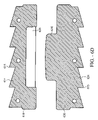
- FIG. 6A is a rear view of an alternate embodiment of the invention having two plates.
- FIG. 6B and FIG. 6C show perspective views of the first and second inner surfaces of the first end plate and the second end plate of an alternative embodiment of implant 600 .
- FIG. 6D is a cross sectional view of the embodiment shown in FIG. 6A .
- FIG. 7A is a top view of an embodiment of a cutting tool of the invention used to prepare the vertebral bodies for the implant.
- FIG. 7B is a side view of the embodiment of the cutting tool of the invention from the distal end.
- FIG. 7C is a distal end view of an embodiment of the cutting tool of the invention.
- FIG. 8A is a side view of an embodiment of the implant lateral insertion tool of the invention.
- FIG. 8B is a top view of the embodiment of the implant lateral insertion tool of the invention.
- FIG. 8C is a distal end view of the embodiment of the implant lateral insertion tool of the invention.
- FIG. 8D is a top view of an embodiment of the implant lateral insertion tool holding an embodiment of the implant.
- FIG. 9 is a block diagram illustrating the steps of a method for inserting the implant between vertebral bodies.
- FIG. 1A shows an embodiment of the implant 100 having a four-piece configuration.
- the designations, “A” for anterior, “P” for posterior, “RL” for right lateral, and “LL” for left lateral are given in the drawings for spatial orientation. These designations give the relationship of all faces of embodiments of the disclosed intervertebral implant from the superior perspective; i.e. looking down the axis of the spine.
- the implant 100 has a pair 131 of first end plates, or upper end plates 110 that are configured to mate with a first vertebra.
- the upper end plate 110 of implant 100 has a first outer surface 112 from which a first keel 114 extends with a first set of teeth 115 .
- the implant 100 has a pair 133 of second end plates, or lower end plates 120 that are configured to mate with a second vertebra.
- the lower end plate 120 has a second outer surface 122 from which a keel 124 extends with a second set of teeth 125 .
- a pair of pivoting or articulating elements or spacers 130 that are part of the pair 133 of lower end plates 120 acts as an articulating element, or spacer between the first end plate 110 and the second end plate 120 and facilitates pivotal or rotational and also twisting movement of the first end plate 110 and the second end plate 120 , relative to each other.
- the pair of articulating elements, or spacers 130 is curved or convex, as will be discussed in more detail below.
- FIG. 6A illustrates a posterior view of an alternate embodiment of the implant shown in FIG. 1A .
- the implant 600 of FIG. 6A is in the form of a two-piece implant 600 having a first end plate 610 and a second end plate 620 .
- the first end plate, or upper end plate 610 is configured to mate with a first vertebra
- a second end plate, or lower end plate 620 is configured to mate with a second vertebra.
- the first inner surface 616 of the upper end plate 610 has a socket or first cavity 636 formed therein.
- a pivoting or articulation element, or spacer 630 is formed on second end plate 620 .
- the spacer 630 at least partially engages the first socket 636 , and facilitates pivotal or rotational and also twisting movement of the first end plate 610 and the second end plate 620 , relative to each other.
- the spacer 630 and corresponding socket 636 are dimensioned so that they are hemi-cylindrical ( FIG. 6D ), while in another embodiment shown in FIG. 6B and FIG. 6C , the articulating element, or spacer 630 and corresponding socket 636 are hemispherical.
- the upper end plate 610 of implant 600 has a first outer surface 612 from which a first keel 614 extends with a first set of teeth 615 .
- first keel 614 when implant 600 is inserted between vertebrae, the first keel 614 extends longitudinally across the first outer surface 612 , about perpendicular to the sagittal plane of the spine. In another embodiment, the first keel 614 extends longitudinally only partially across the first outer surface 612 , about perpendicular to the sagittal plane of the spine.
- the teeth 615 in the two embodiments with complete or partial extension of the keel 614 across the first outer surface 612 of the upper end plate 610 point towards the left lateral face of implant 600 when the embodiment is meant to be put into a slot in a vertebral body from the left lateral approach to the spine.
- This orientation is shown in the figures, and is particularly evident where the keel 614 is fully displayed, as in FIG. 1A and FIG. 6A , for example.
- the teeth 615 point towards the right lateral face of implant 600 when the embodiments are meant to be put into a slot in a vertebral body from the right lateral approach to the spine.
- the first outer surface 612 abuts the vertebral body when the implant 600 is implanted.
- the first keel 614 extends into the vertebral body to anchor implant 600 into position, and is perpendicular to the median sagittal plane of the spine, in which extension and flexion occur.
- the first keel 614 in this orientation offers substantial stability during extension and flexion for the implant 600 inserted between the vertebrae of a patient.
- the first keel 614 in this embodiment is preferably aligned with and supports the articulation of implant 600 .
- the first inner surface 616 with socket 636 at least partially engages the spacer 630 of the implant and opposes the second end plate 620 .
- the first inner surface 616 can form a planar surface that is parallel to the first outer surface 612 , or can form a planar surface that is not parallel to the first outer surface 612 .
- the lower end plate 620 has a second outer surface 622 from which a keel 624 extends with a second set of teeth 625 .
- the second keel 624 when implant 600 is inserted between vertebrae, is about perpendicular to the sagittal plane of the spine.
- the second keel 624 extends longitudinally across the second outer surface 622
- the second keel 624 extends longitudinally partially across the second outer surface 622 .
- the teeth 625 in the two embodiments with complete or partial extension of the second keel 624 across the second outer surface 622 of the lower end plate 620 point towards the left lateral face of implant 600 when the embodiment is meant to be put into a slot in a vertebral body from the left lateral approach to the spine.
- This orientation is shown in the figures, and is particularly evident where the second keel 624 is fully displayed, as in FIG. 1A and FIG. 6A , for example.
- the teeth 625 point towards the right lateral face of implant 600 when the embodiments are meant to be put into a slot in a vertebral body from the right lateral approach to the spine.
- the second outer surface 622 abuts the vertebral body when the implant 600 is implanted.
- the second keel 624 extends into the vertebral body to anchor implant 600 into position, and is perpendicular to the median sagittal plane of the spine, in which extension and flexion occur.
- the second keel 624 in this orientation offers substantial stability during extension and flexion for the implant 600 inserted between the vertebrae of a patient.
- the second keel 624 in this embodiment is aligned with and supports the articulation of implant 600 .
- the second end plate 620 with second inner surface 626 having the spacer 630 opposes the first end plate 610 with first inner surface 616 having socket 636 .
- the spacer 630 of second inner surface 626 at least partially engages socket 636 of first upper surface.
- the second inner surface 626 can form a planar surface that is parallel to the second outer surface 622 , or can form a planar surface that is not parallel to the second outer surface 622 .
- the first inner surface 616 of the first end plate 610 can be parallel to the second inner surface 626 of the second end plate 620 when the implant 600 is assembled and is in a neutral position (i.e., the position where the first end plate 610 has not rotated relative to the second end plate 620 ).
- the first inner surface 616 of the first end plate 610 can be non-parallel to the planar surface of the second inner surface 626 of the second end plate 620 when the implant 600 is assembled and in a neutral position. This non-parallel orientation of the first end plate 610 and the second end plate 620 allows the plates to pivot to a greater degree with respect to each other.
- factors such as the height and position of the spacer 630 , and the, can also be adjusted in order to increase the degree that the first end plate 610 and the second end plate 620 can pivot relative to each other. Other factors that effect the degree of movement of the first end plates 110 or 610 relative to the second end plates 120 or 620 for implant 100 or implant 600 will discussed below.
- the planar surfaces corresponding to the first and second outer surfaces 612 , 622 and the first and second inner surfaces 616 , 626 of the first and second end plates 610 , 620 lie within, or substantially within, the axial plane of the body.
- the first and second keels 614 , 624 are aligned in the axial plane, or perpendicular to the sagittal plane of the vertebrae.
- the first and second keels 614 , 624 extend into the vertebral bodies to anchor implant 600 into position, and are perpendicular to the median sagittal plane of the spine, in which extension and flexion occur.
- the first and second keels 614 , 624 in this orientation offer substantial stability during extension and flexion for implant 600 inserted between the vertebrae of a patient. Additionally, the first and second keels 614 , 624 in this embodiment are aligned with and support the axis of articulation of implant 600 defined by an RL to LL orientation.
- the lateral orientation of the keels allow the implants to be inserted into the spine using a lateral approach as opposed to an anterior or posterior approach.
- the lateral approach is advantageous, because the spinal nerves in the spinal cavity are minimally undisturbed when the implants are inserted laterally into the spine. In comparison to a posterior insertion approach in which the spinal nerves can be substantially disturbed, the spinal nerves are bypassed and relatively undisturbed when the implant is inserted laterally between the vertebral bodies from the side of the spine.
- an anterior insertion approach has its benefits
- the lateral insertion approach can allow the present implant and associated implantation tools, to be inserted into the spine with less disturbance of the patient's internal organs. This can translate into less time and risk associated with preparing the spine for insertion as well as inserting the implant itself into the spine.
- the laterally oriented keels offer substantial stability to the vertebral bodies during extension, flexion and lateral bending of the spine.
- the first and second keels 114 , 124 and 614 , 624 include ports 148 , 152 and 648 , 652 , respectively, that facilitate bone ingrowth.
- bone from the vertebral bodies can grow thorough the ports 148 , 152 and 648 , 652 , and aid in securing the first and second keels 114 , 124 and 614 , 624 , and thereby for securing implants 100 and 600 once inserted between vertebral bodies.
- surfaces defined by the first and second keels 114 , 124 and 614 , 624 and the first and second outer surfaces 112 , 122 and 612 , 622 of implants 100 and 600 can be roughened in order to promote bone ingrowth into these defined surfaces of implants 100 and 600 .
- the ports 148 , 152 and 648 , 652 , the first and second keels 114 , 124 and 614 , 624 , and the first and second outer surfaces 112 , 122 and 612 , 622 of implant 600 can be coated with materials that promote bone growth such as for example bone morphogenic protein, BMP, or structural materials such as hyaluronic acid, HA, or other substance which promotes growth of bone relative to and into the keels 614 , 624 , keel ports 648 , 652 , and other external surfaces of the implant 600 .
- materials that promote bone growth such as for example bone morphogenic protein, BMP, or structural materials such as hyaluronic acid, HA, or other substance which promotes growth of bone relative to and into the keels 614 , 624 , keel ports 648 , 652 , and other external surfaces of the implant 600 .
- FIG. 1A and FIG. 6A can be used to create a three-piece implant as will also be appreciated by those of ordinary skill in the art.
- the first end plate 610 of FIG. 6A with its socket 636 from a two-piece embodiment can be combined with two second end plates 120 of FIG. 1A from a four-piece embodiment to form an implant.
- the second end plate 620 with spacer 630 of a two piece embodiment, such as FIG. 6A can be combined with two first end plates 110 from a four-piece design, such as FIG. 1A , to achieve an implant.
- the features described herein for an interspinous implant for lateral insertion between adjacent vertebrae are applicable to two-, three-, or four-piece embodiments. None of these configurations depart from the scope of the invention.
- FIG. 1B depicts the pair 131 of first or upper end plates 110 and the pair 133 of second or lower end plates 120 in cross-section.
- Each upper and lower end plate 110 , 120 has a keel 114 , 124 with a set of teeth 115 , 125 .
- different embodiments of implant 100 may have complete or partial extension of the first and second keels 114 , 124 across the first and second outer surfaces 112 , 122 of the upper and lower end plates 110 , 120 .
- the teeth 115 , 125 point towards the left lateral face of implant 100 when the embodiment is meant to be put into a slot in a vertebral body from the left lateral approach to the spine, and alternatively, the teeth 115 , 125 point towards the right lateral face of implant 100 when the embodiments are meant to be put into a slot in a vertebral body from the right lateral approach to the spine.
- the socket 136 formed in the first inner surface 116 of first end plate 110 has a first elongated sidewall 150 , a corresponding second elongated sidewall 152 (shown in FIG. 3B ), an end wall 154 , and an open end 156 .
- the open ends 156 of each of the first end plates 110 are oriented so that the open ends 156 face each other.
- Each of the first and second end plates 110 , 120 has a first end 138 , 141 and a second end 139 , 143 .
- the ends 139 of the first end plate 110 face each other, as do the ends 143 of the second end plate 120 .
- the lower plates 120 each have an articulating element, or spacer 130 , which is convex and hemi-cylindrical, that engage the socket 136 .
- the concave hemi-cylindrical inner surface 135 of the socket 136 is sloped to allow the pair 131 of first or upper end plates 110 to easily slide, or rock, side-to-side on the articulating element, or spacer 130 and slide, or ride, forward and backward with enough looseness of fit to allow for some twisting in order to emulate the motion of the vertebral bone and intervertebral disk tissue.
- This arrangement thus, has a sliding or translating pivot point. It is evident from FIG.
- first and second keels 114 , 124 are aligned with and support the axis of articulation of the upper end plate 110 about the spacer 130 for this embodiment.
- This axis of articulation is longitudinally oriented with respect to the vertebrae, or about perpendicular to the sagittal plane of the spine.
- the alignment of the first and second keels 114 , 124 with the axis of articulation offers substantial stability during flexion and extension when implant 100 is inserted between the vertebrae of a patient.
- the articulating element, or spacer 130 has four sides: a first elongated sidewall 140 , a second elongated sidewall 142 , a third end wall 143 , and a fourth end wall 146 .
- the third end wall 144 is flush with the end 143 of the lower end plate 120 of the implant.
- the third end wall 144 has a profile height 160 and the fourth end wall 146 has a profile height 162 . Comparing the profile heights 160 , 162 to each other at the same point on the second inner surface 126 of the second end plate 120 , the overall profile height of the third end wall 144 is greater than the fourth end wall 146 (i.e., 160 > 162 ).
- socket 136 slopes downwardly from the end wall 144 to the end wall 146 .
- spacers 130 comprise an articulating element that has a high surface where the third end walls 144 abut each other and slope to a lower surface adjacent to fourth end walls 146 .
- the edges of the articulating element or spacer 130 are eased or rounded to allow for further range of motion of the pair 131 of upper end plates 110 relative to the pair 133 of lower end plates 120 .
- the overall height of the third end wall 144 and the fourth end wall 146 can be equivalent while still having an effective third end wall height 160 that is greater than the effective fourth end wall height 162 due to the overall slope of the second inner surface 126 .
- the overall height of the third end wall 144 and the fourth end wall 146 can be different with the third end wall 144 having a height greater than the fourth end wall 146 , thus eliminating the need for the second inner surface 126 to have a slope or further increasing the net difference between the height of the third end wall and the forth end wall.
- the spacer 130 is depicted such that the third end wall 144 is flush with the second end 143 , those of skill in the art will appreciate that the spacer 130 could also be configured such that the third end wall 144 is recessed relative to the end 143 of the second end plate. In such a configuration, the third end wall 144 and the end 143 would not be flush.
- FIGS. 1D and 1E illustrate posterior views of the implant 100 showing the clearance for left and right lateral bending.
- left and right lateral bending ranges from 3-5°.
- the length of the spacer 130 can be less than the length of the socket 136 .
- the open ends 156 of the sockets facilitate movement of the articulating elements, or spacers 130 within the socket 136 to accommodate side-bending movement.
- FIG. 2A and FIG. 2B are views of the intervertebral implant 100 , which depict the motion of the first end plate 110 relative to the second end plate 120 .
- a side view of implant 100 is depicted, showing first end plate 110 with socket 136 and the second end plate 120 with the articulating element or spacer 130 .
- the sloping of the first inner surface 116 of the first end plate 110 facilitates rotation of the spacer and socket in an anterior A direction and a posterior P direction.
- the first inner surface 116 slopes from a high point at about where the socket is located to low points at the ends 111 and 113 of the upper end plate 110 .
- the implant 100 is positioned to achieve flexion (i.e., forward bending) in a range up to about 15°, but more preferably 10°, while in FIG. 2B , the implant 100 is positioned to achieve extension (i.e., backward bending) in a preferable range of up to about 5°.
- flexion i.e., forward bending
- extension i.e., backward bending
- FIG. 2C and FIG. 2D show cross sections of implant 100 through the sagittal plane of the vertebrae.
- FIG. 2C is a cross-section of the side view of the intervertebral implant 100 showing the mating of the spacer 130 to the socket 136 .
- FIG. 2D illustrates an alternate embodiment of the first end plate 110 wherein the socket 136 has ridges 268 , 269 forming a protuberance that extends into the channel 264 , 265 respectively on the second end plate 120 .
- the protuberances 268 , 269 can extend partially into the channel, such as the configuration shown, or can have a channel conforming shape such that when the spacer and socket are moved to achieve flexion 272 or extension 274 the protuberance or ridge 268 , 269 extends into the channels 264 , 265 .
- This embodiment allows the first inner surface 116 and second inner surface 126 of the first end plate 110 and the second end plate 120 to be flat and non-sloping as shown while still allowing for the implant to emulate forward and backward bending and allow for the blocking of the motion of the socket relative to the spacer.
- first and second keels 114 , 124 are aligned with and support the articulation of first end plate 110 about the spacer 130 for this embodiment, and where the articulation is about perpendicular to the sagittal plane of the spine.
- FIG. 3A a top view of one-half of the intervertebral implant 100 is shown.
- Each of the top first end plate 110 and the bottom second end plate 120 have a bores 376 for receiving pins of an implant tool.
- the first keel 114 on the first end plate 110 is positioned so that it is aligned in the same plane with the second keel 124 on the second end plate 120 .
- the length of spacer 130 from the third end wall 144 to the fourth end wall 146 is shorter than the length of the socket 136 from the end wall 154 to the open end 156 , so that the fit of the spacer with the socket is somewhat loose.
- implant 100 of this embodiment allows the spine to have movement in three orthogonal degrees of freedom, namely (1) forward and backward bending movement, (2) lateral side-to-side bending, and (3) twisting movement.
- FIGS. 3B and 3C show the relative rotation of the first or upper end plate 110 to the second or lower end plate 120 to achieve rotation about a central axis 378 . This rotation results in about a 3°-6° rotation about the axis (i.e., 3° of torso twisting in each direction).
- FIG. 4A and FIG. 4B show views of the first and second end plates, 110 , 120 .
- FIG. 4A shows a perspective view of a second end plate 120 of the intervertebral implant 100 .
- the second inner surface 126 of the second end plate 120 is shown with a hemi-cylindrical spacer 130 formed therefrom, and channels or grooves 264 , 265 extending about the spacer 130 .
- the channels 264 , 265 are formed on two sides of the spacer 130 .
- the channels 264 , 265 can alternatively surround the spacer 130 .
- FIG. 4B shows a perspective view of the first end plate 110 , with a first inner surface 116 that opposes the second inner surface 126 .
- the first inner surface 116 has a hemi-cylindrical socket 136 formed therein.
- the socket 136 of FIG. 4B is configured to mate with the spacer 130 of FIG. 4A .
- FIG. 4C and FIG. 4D show views of the first and second end plates, 110 , 120 for an alternative embodiment of implant 100 .
- FIG. 4C shows a perspective view of an embodiment of the second inner surface 126 of the second or lower end plate 120 of implant 100 .
- the second inner surface 126 of the lower end plate 120 has a hemispherical spacer 130 formed therefrom.
- FIG. 4 d shows a perspective view of an embodiment of the first inner surface 116 of the first or upper end plate 110 of implant 100 , which opposes the second inner surface 126 .
- the first inner surface 116 of the upper end plate 110 has a socket or cavity 136 formed therein.
- the socket 136 has a concave hemispherical surface.
- the socket 136 allows the first end plate 110 to pivot or rotate on spacer 130 .
- first and second keels 114 , 124 are aligned with and support the articulation of the first end plate 110 about the spacer 130 , relative to the second end plate 120 .
- the first and second keels 114 , 124 in this orientation offer substantial stability during extension and flexion for implant 100 inserted between the vertebrae of a patient.
- the first and second keels 114 , 124 in these embodiments are aligned with and support the lateral axis of articulation of implant 100 , which is perpendicular to the sagittal plane of the spine. Additionally, as evidenced from the perspective views of FIG. 4A and FIG.
- the perimeter shape of the upper and lower end plates 110 , 120 can be configured to correspond to the perimeter shape of a vertebral disk. As will be appreciated by those of ordinary skill in the art, the perimeter shape of the upper end plate 110 and the lower end plate 120 can be the same.
- FIG. 5A and FIG. 5B show the implant after insertion between the vertebrae of a patient.
- FIG. 5A illustrates a posterior view of the implant shown in FIG. 1A implanted between vertebral bodies in a spine.
- FIG. 5A illustrates the spinal column 500 and the cauda equina 504 (a collection of lumbar and sacral nerve roots that fill the caudal end of the spinal cord) with individual nerves 506 exiting the cord between lumbar vertebrae.
- the implant 100 is positioned between two vertebral bodies 520 , 521 such that the first and second keels 114 , 124 lie in a plane parallel to coronal or frontal plane of the body, or perpendicular to the sagittal plane of the vertebrae.
- FIG. 5B illustrates a side view of the implant inserted between vertebral bodies 520 , 521 , for embodiments of the implant as that shown in FIG. 1A , or FIG. 6A .
- the gap between the first end plate 110 and the second end plate 120 at the anterior “A” face of implants 100 , 600 is greater than at the posterior “P” face of implants 100 , 600 .
- the greater gap at the anterior face vs. the posterior face of implants 100 , 600 results in the flexion (forward bending) movement being facilitated to a greater degree than extension (backward bending) movement.
- flexion forward bending
- backward bending extension
- These embodiments show implants 100 , 600 inserted between two vertebrae with two first keels 114 extending from the first end plate 110 , and two second keels 124 extending from the second end plate 120 .
- the first and second keels 114 , 124 are about perpendicular to the sagittal plane of the spine, and support the articulation of the first end plate 110 relative to the second end plate 120 , about the spacer 130 .
- implants 100 , 600 can be made of medical grade titanium, stainless steel or cobalt chrome. Other materials that have appropriate structural strength and that are suitable for implantation into a patient can also be used.
- One class of materials contemplated for use in implant 100 is the class of biocompatible polymers. Copolymers, blends and composites of polymers are also contemplated for fabrication of parts of the disclosed device.
- a copolymer is a polymer derived from more than one species of monomer.
- a polymer composite is a heterogeneous combination of two or more materials, wherein the constituents are not miscible, and therefore exhibit an interface between one another.
- a polymer blend is a macroscopically homogeneous mixture of two or more different species of polymer.
- biocompatible polymers are the polyaryl ester ketones which has several members, which include polyetheretherketone (PEEK), and polyetherketoneketone (PEKK).
- PEEK has proven as a durable material for implants, as well as meeting criteria of biocompatibility.
- Medical grade PEEK is available from Victrex Corporation under the product name PEEK-OPTIMA.
- Medical grade PEKK is available from Oxford Performance Materials under the name OXPEKK, and also from CoorsTek under the name BioPEKK.
- Still another interesting group of biocompatible polymers are polyalkyl biocompatible polymers, such as polyethylenes, polypropylenes, and the like.
- These medical grade biocompatible polymers are also available as reinforced polymer materials.
- fillers are added to a polymer, copolymer, polymer blend, or polymer composite. Fillers are added to modify properties, such as mechanical, optical, and thermal properties. In this case, fillers, such as carbon fibers, are added to reinforce the polymers mechanically to enhance strength for certain uses, such as load bearing devices.
- FIG. 7A through 7D show an embodiment of a tool for preparing vertebral bodies to receive implants 100 , 600
- FIG. 8A through FIG. 8D show an embodiment of a tool for inserting embodiments of the disclosed intervertebral implants 100 , 600 .
- FIG. 7A through FIG. 7C are the top view, the side view, and an end view of the cutting tool 700 .
- the cutting tool 700 has a handle 710 at its proximal end for controlling the tool during operation.
- the handle 710 can be removable or affixed to the cutting end.
- the distal end 702 of the tool 700 is solid head has an upper surface 705 , and a lower surface 706 .
- the upper surface 705 has a first blade 712 mounted thereon, and the lower surface 706 has a second blade 714 mounted thereon.
- the first blade 712 is about centered with the upper surface 705
- the second blade 714 is about centered with the lower surface 706 .
- the first and second blades 712 , 714 are oriented to cut a space in a first and second intervertebral body for the first and second keels 114 , 124 of implants 100 , 600 .
- the space is perpendicular to the sagittal plane of the vertebrae, and allows for the lateral insertion of the implants 100 , 600 .
- FIG. 7C is a view of the distal end of the cutting tool 700 showing the beveled end 716 and the first and second blades 712 , 714 .
- the height h of the head 702 of the cutting tool 700 approximates the distance between two vertebral bodies or the height of the disk space. In this embodiment of cutting tool 700 , the blades 712 , 714 extend above and below the head 702 .
- the tool shown in FIG. 7A can be modified such that instead of cutting keel-receiving channels in the upper and lower vertebral bodies at the same time, two tools are provided so that only one vertebral body is cut for keel-receiving channels at a time.
- an alternative embodiment of cutting tool 700 has a first tool with a single blade mounted on the head 702 .
- a second tool could be provided having a single blade mounted on the head 702 , and additionally on the opposing surface, a guide. The guide on the surface opposite the surface with the blade is designed to engage with the first keel receiving channel cut the first vertebrae with the first tool to ensure that the second cut is optimally aligned with the first cut.
- FIG. 8A through FIG. 8D depict an embodiment of the implanting tool used to insert the implant 600 of FIG. 6A between vertebral bodies.
- FIG. 8A is a side view of the implantation tool 800 that has a handle 810 and an implant holder 820 .
- the implant holder 820 has an implant conforming surface 824 and four pins 822 for holding the first end plate 610 and the second end plate 620 implant 600 .
- the conforming surface 824 is curved to follow the convex outer LL edges of the first and second end plates 610 , 620 , respectively, for an implant inserted from the left lateral side of a patient.
- the implant 600 nests within a conforming surface 824 and is held by pins 822 .
- FIG. 8C shows the distal view of the end of the tool with four pins 822 for securing the first and second end plate of the implant.
- kits can be assembled that include an implant 100 (or 600 ) sized for a particular patient.
- the kit could also include several cutting tools 700 and several implanting tools 800 or a single handle that cooperates with cutting ends 702 and implantation ends 820 .
- FIG. 9 is a block diagram showing the basic steps of the method for laterally inserting the embodiments of implants 100 , 600 .
- a tool, such as the one depicted in FIG. 7A is inserted laterally between the vertebral bodies to create channels in the bodies to receive the keels of the implant.
- the implant is then inserted laterally 930 between two vertebrae and the wound is closed 940 . This procedure can be followed for either a left lateral approach or right lateral approach.
- the teeth 115 , 125 of upper and lower keels 114 , 124 would be pointed towards the left lateral face of the device in order to aid in retaining embodiments of implants 100 , 600 in place.
- the teeth would point towards the right lateral face of the device.
Abstract
Description
Claims (22)
Priority Applications (1)
| Application Number | Priority Date | Filing Date | Title |
|---|---|---|---|
| US10/981,807 US7503935B2 (en) | 2003-12-02 | 2004-11-05 | Method of laterally inserting an artificial vertebral disk replacement with translating pivot point |
Applications Claiming Priority (2)
| Application Number | Priority Date | Filing Date | Title |
|---|---|---|---|
| US52672403P | 2003-12-02 | 2003-12-02 | |
| US10/981,807 US7503935B2 (en) | 2003-12-02 | 2004-11-05 | Method of laterally inserting an artificial vertebral disk replacement with translating pivot point |
Publications (2)
| Publication Number | Publication Date |
|---|---|
| US20050143820A1 US20050143820A1 (en) | 2005-06-30 |
| US7503935B2 true US7503935B2 (en) | 2009-03-17 |
Family
ID=34704248
Family Applications (2)
| Application Number | Title | Priority Date | Filing Date |
|---|---|---|---|
| US10/981,863 Abandoned US20050154462A1 (en) | 2003-12-02 | 2004-11-05 | Laterally insertable artificial vertebral disk replacement implant with translating pivot point |
| US10/981,807 Expired - Fee Related US7503935B2 (en) | 2003-12-02 | 2004-11-05 | Method of laterally inserting an artificial vertebral disk replacement with translating pivot point |
Family Applications Before (1)
| Application Number | Title | Priority Date | Filing Date |
|---|---|---|---|
| US10/981,863 Abandoned US20050154462A1 (en) | 2003-12-02 | 2004-11-05 | Laterally insertable artificial vertebral disk replacement implant with translating pivot point |
Country Status (1)
| Country | Link |
|---|---|
| US (2) | US20050154462A1 (en) |
Cited By (59)
| Publication number | Priority date | Publication date | Assignee | Title |
|---|---|---|---|---|
| US20050033435A1 (en) * | 2003-08-04 | 2005-02-10 | Spine Next | Intervertebral disk prosthesis |
| US20070100212A1 (en) * | 2004-10-08 | 2007-05-03 | Nuvasive, Inc. | Surgical access system and related methods |
| US20070173832A1 (en) * | 2004-10-20 | 2007-07-26 | Vertiflex, Inc. | Systems and methods for posterior dynamic stabilization of the spine |
| US20080287997A1 (en) * | 2004-10-20 | 2008-11-20 | Moti Altarac | Interspinous spacer |
| US20080319550A1 (en) * | 2004-10-20 | 2008-12-25 | Moti Altarac | Interspinous spacer |
| US20090054988A1 (en) * | 2007-05-01 | 2009-02-26 | Harold Hess | Interspinous implants and methods for implanting same |
| US20090138046A1 (en) * | 2004-10-20 | 2009-05-28 | Moti Altarac | Interspinous spacer |
| US20090138055A1 (en) * | 2004-10-20 | 2009-05-28 | Moti Altarac | Spacer insertion instrument |
| US20090222043A1 (en) * | 2004-10-20 | 2009-09-03 | Moti Altarac | Interspinous process spacer instrument system with deployment indicator |
| US20090292316A1 (en) * | 2007-05-01 | 2009-11-26 | Harold Hess | Interspinous process implants having deployable engagement arms |
| US20100004749A1 (en) * | 2008-07-03 | 2010-01-07 | Aesculap Ag | Intervertebral disk prosthesis system |
| US20100094422A1 (en) * | 2008-10-13 | 2010-04-15 | Noah Hansell | Intervertebral Spacer |
| US20100204737A1 (en) * | 2009-02-11 | 2010-08-12 | IMDS, Inc. | Intervertebral implant with integrated fixation |
| US20100234889A1 (en) * | 2009-03-13 | 2010-09-16 | Harold Hess | Interspinous Process Implant and Fusion Cage Spacer |
| US20100331982A1 (en) * | 2005-11-04 | 2010-12-30 | Mccombe Peter | Method of Reducing Loading Failure for a Prosthetic Component |
| US8012207B2 (en) | 2004-10-20 | 2011-09-06 | Vertiflex, Inc. | Systems and methods for posterior dynamic stabilization of the spine |
| US8123807B2 (en) | 2004-10-20 | 2012-02-28 | Vertiflex, Inc. | Systems and methods for posterior dynamic stabilization of the spine |
| US8128662B2 (en) | 2004-10-20 | 2012-03-06 | Vertiflex, Inc. | Minimally invasive tooling for delivery of interspinous spacer |
| US8152837B2 (en) | 2004-10-20 | 2012-04-10 | The Board Of Trustees Of The Leland Stanford Junior University | Systems and methods for posterior dynamic stabilization of the spine |
| US8167944B2 (en) | 2004-10-20 | 2012-05-01 | The Board Of Trustees Of The Leland Stanford Junior University | Systems and methods for posterior dynamic stabilization of the spine |
| US8277488B2 (en) | 2004-10-20 | 2012-10-02 | Vertiflex, Inc. | Interspinous spacer |
| US8292922B2 (en) | 2004-10-20 | 2012-10-23 | Vertiflex, Inc. | Interspinous spacer |
| US8317864B2 (en) | 2004-10-20 | 2012-11-27 | The Board Of Trustees Of The Leland Stanford Junior University | Systems and methods for posterior dynamic stabilization of the spine |
| US8409282B2 (en) | 2004-10-20 | 2013-04-02 | Vertiflex, Inc. | Systems and methods for posterior dynamic stabilization of the spine |
| US20130110240A1 (en) * | 2011-10-26 | 2013-05-02 | Noah Hansell | Artificial Discs |
| US8512408B2 (en) | 2010-12-17 | 2013-08-20 | Warsaw Orthopedic, Inc. | Flexiable spinal implant |
| US8628574B2 (en) | 2004-10-20 | 2014-01-14 | Vertiflex, Inc. | Systems and methods for posterior dynamic stabilization of the spine |
| US8740948B2 (en) | 2009-12-15 | 2014-06-03 | Vertiflex, Inc. | Spinal spacer for cervical and other vertebra, and associated systems and methods |
| US8845726B2 (en) | 2006-10-18 | 2014-09-30 | Vertiflex, Inc. | Dilator |
| US9023084B2 (en) | 2004-10-20 | 2015-05-05 | The Board Of Trustees Of The Leland Stanford Junior University | Systems and methods for stabilizing the motion or adjusting the position of the spine |
| US9033993B2 (en) | 2009-11-03 | 2015-05-19 | Howmedica Osteonics Corp. | Intervertebral implant with integrated fixation |
| US9119680B2 (en) | 2004-10-20 | 2015-09-01 | Vertiflex, Inc. | Interspinous spacer |
| US9161783B2 (en) | 2004-10-20 | 2015-10-20 | Vertiflex, Inc. | Interspinous spacer |
| US9254130B2 (en) | 2011-11-01 | 2016-02-09 | Hyun Bae | Blade anchor systems for bone fusion |
| US9259327B2 (en) | 2008-10-13 | 2016-02-16 | Globus Medical, Inc. | Articulating spacer |
| US9358122B2 (en) | 2011-01-07 | 2016-06-07 | K2M, Inc. | Interbody spacer |
| US9393055B2 (en) | 2004-10-20 | 2016-07-19 | Vertiflex, Inc. | Spacer insertion instrument |
| US20160270928A1 (en) * | 2015-03-18 | 2016-09-22 | Baui Biotech Co., Ltd. | Spinal spacer |
| US9480511B2 (en) | 2009-12-17 | 2016-11-01 | Engage Medical Holdings, Llc | Blade fixation for ankle fusion and arthroplasty |
| US9615856B2 (en) | 2011-11-01 | 2017-04-11 | Imds Llc | Sacroiliac fusion cage |
| US9675303B2 (en) | 2013-03-15 | 2017-06-13 | Vertiflex, Inc. | Visualization systems, instruments and methods of using the same in spinal decompression procedures |
| US9700434B2 (en) | 2009-08-10 | 2017-07-11 | Howmedica Osteonics Corp. | Intervertebral implant with integrated fixation |
| US9730802B1 (en) | 2014-01-14 | 2017-08-15 | Nuvasive, Inc. | Spinal fusion implant and related methods |
| US9757164B2 (en) | 2013-01-07 | 2017-09-12 | Spinal Simplicity Llc | Interspinous process implant having deployable anchor blades |
| US9861399B2 (en) | 2009-03-13 | 2018-01-09 | Spinal Simplicity, Llc | Interspinous process implant having a body with a removable end portion |
| US9925051B2 (en) | 2010-12-16 | 2018-03-27 | Engage Medical Holdings, Llc | Arthroplasty systems and methods |
| US10182923B2 (en) | 2015-01-14 | 2019-01-22 | Stryker European Holdings I, Llc | Spinal implant with porous and solid surfaces |
| US10226354B2 (en) | 2005-04-06 | 2019-03-12 | Nuvasive, Inc. | Prosthesis |
| US10238382B2 (en) | 2012-03-26 | 2019-03-26 | Engage Medical Holdings, Llc | Blade anchor for foot and ankle |
| US10390955B2 (en) | 2016-09-22 | 2019-08-27 | Engage Medical Holdings, Llc | Bone implants |
| US10456272B2 (en) | 2017-03-03 | 2019-10-29 | Engage Uni Llc | Unicompartmental knee arthroplasty |
| US10478313B1 (en) | 2014-01-10 | 2019-11-19 | Nuvasive, Inc. | Spinal fusion implant and related methods |
| US10524772B2 (en) | 2014-05-07 | 2020-01-07 | Vertiflex, Inc. | Spinal nerve decompression systems, dilation systems, and methods of using the same |
| US10537666B2 (en) | 2015-05-18 | 2020-01-21 | Stryker European Holdings I, Llc | Partially resorbable implants and methods |
| US10835388B2 (en) | 2017-09-20 | 2020-11-17 | Stryker European Operations Holdings Llc | Spinal implants |
| US20220008211A1 (en) * | 2020-07-08 | 2022-01-13 | Ctl Medical Corporation | Cage with keel |
| US11266510B2 (en) | 2015-01-14 | 2022-03-08 | Stryker European Operations Holdings Llc | Spinal implant with fluid delivery capabilities |
| US11452618B2 (en) | 2019-09-23 | 2022-09-27 | Dimicron, Inc | Spinal artificial disc removal tool |
| US11540928B2 (en) | 2017-03-03 | 2023-01-03 | Engage Uni Llc | Unicompartmental knee arthroplasty |
Families Citing this family (77)
| Publication number | Priority date | Publication date | Assignee | Title |
|---|---|---|---|---|
| US5836948A (en) * | 1997-01-02 | 1998-11-17 | Saint Francis Medical Technologies, Llc | Spine distraction implant and method |
| US6068630A (en) | 1997-01-02 | 2000-05-30 | St. Francis Medical Technologies, Inc. | Spine distraction implant |
| CA2391330C (en) | 1999-07-02 | 2008-11-18 | Spine Solutions Inc. | Intervertebral implant |
| FR2824261B1 (en) | 2001-05-04 | 2004-05-28 | Ldr Medical | INTERVERTEBRAL DISC PROSTHESIS AND IMPLEMENTATION METHOD AND TOOLS |
| US8388684B2 (en) | 2002-05-23 | 2013-03-05 | Pioneer Signal Technology, Inc. | Artificial disc device |
| FR2846550B1 (en) | 2002-11-05 | 2006-01-13 | Ldr Medical | INTERVERTEBRAL DISC PROSTHESIS |
| JP4410254B2 (en) | 2003-05-14 | 2010-02-03 | キリアン クラウス | Height adjustable implant for insertion between vertebral bodies and corresponding operating tools |
| US7753958B2 (en) | 2003-08-05 | 2010-07-13 | Gordon Charles R | Expandable intervertebral implant |
| US7691146B2 (en) * | 2003-11-21 | 2010-04-06 | Kyphon Sarl | Method of laterally inserting an artificial vertebral disk replacement implant with curved spacer |
| US20050154462A1 (en) * | 2003-12-02 | 2005-07-14 | St. Francis Medical Technologies, Inc. | Laterally insertable artificial vertebral disk replacement implant with translating pivot point |
| DE10357926B3 (en) | 2003-12-11 | 2005-09-01 | Deltacor Gmbh | Length adjustable spinal implant |
| US7771479B2 (en) | 2004-01-09 | 2010-08-10 | Warsaw Orthopedic, Inc. | Dual articulating spinal device and method |
| US7556651B2 (en) | 2004-01-09 | 2009-07-07 | Warsaw Orthopedic, Inc. | Posterior spinal device and method |
| US7901459B2 (en) | 2004-01-09 | 2011-03-08 | Warsaw Orthopedic, Inc. | Split spinal device and method |
| US20050154467A1 (en) * | 2004-01-09 | 2005-07-14 | Sdgi Holdings, Inc. | Interconnected spinal device and method |
| US7550010B2 (en) * | 2004-01-09 | 2009-06-23 | Warsaw Orthopedic, Inc. | Spinal arthroplasty device and method |
| US7875077B2 (en) | 2004-01-09 | 2011-01-25 | Warsaw Orthopedic, Inc. | Support structure device and method |
| FR2865629B1 (en) | 2004-02-04 | 2007-01-26 | Ldr Medical | INTERVERTEBRAL DISC PROSTHESIS |
| PT2113227E (en) | 2004-02-04 | 2015-10-16 | Ldr Medical | Intervertebral disc prosthesis |
| WO2005077013A2 (en) | 2004-02-06 | 2005-08-25 | Georgia Tech Research Corporation | Surface directed cellular attachment |
| CA2558661C (en) | 2004-02-06 | 2012-09-04 | Georgia Tech Research Corporation | Load bearing biocompatible device |
| FR2869528B1 (en) * | 2004-04-28 | 2007-02-02 | Ldr Medical | INTERVERTEBRAL DISC PROSTHESIS |
| US8241330B2 (en) | 2007-01-11 | 2012-08-14 | Lanx, Inc. | Spinous process implants and associated methods |
| CA2614133A1 (en) * | 2004-10-25 | 2006-05-04 | Lanx, Llc | Interspinous distraction devices and associated methods of insertion |
| US7918875B2 (en) * | 2004-10-25 | 2011-04-05 | Lanx, Inc. | Interspinous distraction devices and associated methods of insertion |
| US9055981B2 (en) | 2004-10-25 | 2015-06-16 | Lanx, Inc. | Spinal implants and methods |
| FR2879436B1 (en) | 2004-12-22 | 2007-03-09 | Ldr Medical | INTERVERTEBRAL DISC PROSTHESIS |
| EP1879531A4 (en) * | 2005-05-02 | 2011-08-03 | Seaspine Inc | Motion restoring intervertebral device |
| US7799083B2 (en) * | 2005-05-02 | 2010-09-21 | Seaspine, Inc. | Prosthesis for restoring motion in an appendage or spinal joint and an intervertebral spacer |
| US20060271055A1 (en) * | 2005-05-12 | 2006-11-30 | Jeffery Thramann | Spinal stabilization |
| US8328851B2 (en) | 2005-07-28 | 2012-12-11 | Nuvasive, Inc. | Total disc replacement system and related methods |
| FR2891135B1 (en) | 2005-09-23 | 2008-09-12 | Ldr Medical Sarl | INTERVERTEBRAL DISC PROSTHESIS |
| US7967862B2 (en) * | 2005-11-23 | 2011-06-28 | Warsaw Orthopedic, Inc. | Posterior articular disc and method for implantation |
| FR2893838B1 (en) | 2005-11-30 | 2008-08-08 | Ldr Medical Soc Par Actions Si | PROSTHESIS OF INTERVERTEBRAL DISC AND INSTRUMENTATION OF INSERTION OF THE PROSTHESIS BETWEEN VERTEBRATES |
| US8038920B2 (en) * | 2006-01-25 | 2011-10-18 | Carticept Medical, Inc. | Methods of producing PVA hydrogel implants and related devices |
| US8603171B2 (en) * | 2006-01-25 | 2013-12-10 | Mimedx Group, Inc. | Spinal disc implants with flexible keels and methods of fabricating implants |
| US20070173941A1 (en) * | 2006-01-25 | 2007-07-26 | Sdgi Holdings, Inc. | Intervertebral prosthetic disc and method of installing same |
| US7811326B2 (en) | 2006-01-30 | 2010-10-12 | Warsaw Orthopedic Inc. | Posterior joint replacement device |
| US20070270959A1 (en) * | 2006-04-18 | 2007-11-22 | Sdgi Holdings, Inc. | Arthroplasty device |
| US20070288091A1 (en) * | 2006-05-31 | 2007-12-13 | Braddock Danny H | Intervertebral lordatic adapter |
| US7780676B2 (en) * | 2006-07-11 | 2010-08-24 | Ebi, Llc | Intervertebral implantation apparatus |
| WO2008014258A2 (en) | 2006-07-24 | 2008-01-31 | Spine Solutions, Inc. | Intervertebral implant with keel |
| US8409213B2 (en) * | 2006-08-10 | 2013-04-02 | Pioneer Surgical Technology, Inc. | Insertion instrument for artificial discs |
| US7976550B2 (en) * | 2006-08-10 | 2011-07-12 | Pioneer Surgical Technology | Insertion instrument for artificial discs |
| US8118872B2 (en) | 2006-08-10 | 2012-02-21 | Pioneer Surgical Technology, Inc. | System and methods for inserting a spinal disc device into an intervertebral space |
| US8414616B2 (en) * | 2006-09-12 | 2013-04-09 | Pioneer Surgical Technology, Inc. | Mounting devices for fixation devices and insertion instruments used therewith |
| US8372084B2 (en) * | 2006-09-22 | 2013-02-12 | Pioneer Surgical Technology, Inc. | System and methods for inserting a spinal disc device into an intervertebral space |
| WO2008062397A1 (en) * | 2006-11-24 | 2008-05-29 | Flexsis Surgical Ltd. | Articulating spinal spacer |
| US8715352B2 (en) * | 2006-12-14 | 2014-05-06 | Depuy Spine, Inc. | Buckling disc replacement |
| US20080154378A1 (en) * | 2006-12-22 | 2008-06-26 | Warsaw Orthopedic, Inc. | Bone implant having engineered surfaces |
| US9265532B2 (en) | 2007-01-11 | 2016-02-23 | Lanx, Inc. | Interspinous implants and methods |
| US8075596B2 (en) * | 2007-01-12 | 2011-12-13 | Warsaw Orthopedic, Inc. | Spinal prosthesis systems |
| US9066811B2 (en) * | 2007-01-19 | 2015-06-30 | Flexuspine, Inc. | Artificial functional spinal unit system and method for use |
| US8034081B2 (en) | 2007-02-06 | 2011-10-11 | CollabComl, LLC | Interspinous dynamic stabilization implant and method of implanting |
| ES2905157T3 (en) * | 2007-02-09 | 2022-04-07 | Dimicron Inc | Multilobe Spine Joint |
| US8465546B2 (en) | 2007-02-16 | 2013-06-18 | Ldr Medical | Intervertebral disc prosthesis insertion assemblies |
| US8864832B2 (en) | 2007-06-20 | 2014-10-21 | Hh Spinal Llc | Posterior total joint replacement |
| FR2916956B1 (en) | 2007-06-08 | 2012-12-14 | Ldr Medical | INTERSOMATIC CAGE, INTERVERTEBRAL PROSTHESIS, ANCHORING DEVICE AND IMPLANTATION INSTRUMENTATION |
| US10821003B2 (en) | 2007-06-20 | 2020-11-03 | 3Spline Sezc | Spinal osteotomy |
| US20090012619A1 (en) * | 2007-07-03 | 2009-01-08 | Seaspine, Inc. | Motion restoring intervertebral prosthesis with limited angular displacement |
| US9220603B2 (en) * | 2008-07-02 | 2015-12-29 | Simplify Medical, Inc. | Limited motion prosthetic intervertebral disc |
| WO2013025448A1 (en) * | 2011-08-09 | 2013-02-21 | Nuvasive, Inc. | Vertebral body replacement |
| US9687357B2 (en) | 2009-03-12 | 2017-06-27 | Nuvasive, Inc. | Vertebral body replacement |
| BRPI1014864A2 (en) | 2009-03-31 | 2017-03-28 | Lanx Inc | "implantation of spinous processes and associated methods" |
| EP2432429B1 (en) | 2009-05-19 | 2016-03-30 | Synthes GmbH | Dynamic trial implants |
| EP2757964B1 (en) | 2011-05-26 | 2016-05-04 | Cartiva, Inc. | Tapered joint implant and related tools |
| US11812923B2 (en) | 2011-10-07 | 2023-11-14 | Alan Villavicencio | Spinal fixation device |
| US9132021B2 (en) | 2011-10-07 | 2015-09-15 | Pioneer Surgical Technology, Inc. | Intervertebral implant |
| US9526627B2 (en) | 2011-11-17 | 2016-12-27 | Exactech, Inc. | Expandable interbody device system and method |
| US10350072B2 (en) | 2012-05-24 | 2019-07-16 | Cartiva, Inc. | Tooling for creating tapered opening in tissue and related methods |
| US9492288B2 (en) | 2013-02-20 | 2016-11-15 | Flexuspine, Inc. | Expandable fusion device for positioning between adjacent vertebral bodies |
| US9517144B2 (en) | 2014-04-24 | 2016-12-13 | Exactech, Inc. | Limited profile intervertebral implant with incorporated fastening mechanism |
| US10398565B2 (en) | 2014-04-24 | 2019-09-03 | Choice Spine, Llc | Limited profile intervertebral implant with incorporated fastening and locking mechanism |
| WO2016161025A1 (en) | 2015-03-31 | 2016-10-06 | Cartiva, Inc. | Hydrogel implants with porous materials and methods |
| EP3892241A1 (en) | 2015-03-31 | 2021-10-13 | Cartiva, Inc. | Drill bit for carpometacarpal implant |
| JP2020533070A (en) | 2017-09-08 | 2020-11-19 | パイオニア サージカル テクノロジー インコーポレイテッド | Intervertebral implants, instruments, and methods |
| USD907771S1 (en) | 2017-10-09 | 2021-01-12 | Pioneer Surgical Technology, Inc. | Intervertebral implant |
Citations (139)
| Publication number | Priority date | Publication date | Assignee | Title |
|---|---|---|---|---|
| US2456806A (en) | 1947-01-14 | 1948-12-21 | Erwin B Wolffe | Vaginal gauge |
| US2677369A (en) | 1952-03-26 | 1954-05-04 | Fred L Knowles | Apparatus for treatment of the spinal column |
| US3426364A (en) | 1966-08-25 | 1969-02-11 | Colorado State Univ Research F | Prosthetic appliance for replacing one or more natural vertebrae |
| US3867728A (en) | 1971-12-30 | 1975-02-25 | Cutter Lab | Prosthesis for spinal repair |
| US3875595A (en) | 1974-04-15 | 1975-04-08 | Edward C Froning | Intervertebral disc prosthesis and instruments for locating same |
| US4309777A (en) | 1980-11-13 | 1982-01-12 | Patil Arun A | Artificial intervertebral disc |
| US4349921A (en) | 1980-06-13 | 1982-09-21 | Kuntz J David | Intervertebral disc prosthesis |
| US4369769A (en) | 1980-06-13 | 1983-01-25 | Edwards Charles C | Spinal fixation device and method |
| US4401112A (en) | 1980-09-15 | 1983-08-30 | Rezaian Seyed M | Spinal fixator |
| US4479491A (en) | 1982-07-26 | 1984-10-30 | Martin Felix M | Intervertebral stabilization implant |
| US4501269A (en) | 1981-12-11 | 1985-02-26 | Washington State University Research Foundation, Inc. | Process for fusing bone joints |
| US4553273A (en) | 1983-11-23 | 1985-11-19 | Henry Ford Hospital | Vertebral body prosthesis and spine stabilizing method |
| US4554914A (en) | 1983-10-04 | 1985-11-26 | Kapp John P | Prosthetic vertebral body |
| US4599084A (en) | 1983-05-24 | 1986-07-08 | American Hospital Supply Corp. | Method of using biological tissue to promote even bone growth |
| US4599086A (en) | 1985-06-07 | 1986-07-08 | Doty James R | Spine stabilization device and method |
| US4636217A (en) | 1985-04-23 | 1987-01-13 | Regents Of The University Of Minnesota | Anterior spinal implant |
| US4657550A (en) | 1984-12-21 | 1987-04-14 | Daher Youssef H | Buttressing device usable in a vertebral prosthesis |
| US4685447A (en) | 1985-03-25 | 1987-08-11 | Pmt Corporation | Tissue expander system |
| US4696290A (en) | 1983-12-16 | 1987-09-29 | Acromed Corporation | Apparatus for straightening spinal columns |
| US4714469A (en) | 1987-02-26 | 1987-12-22 | Pfizer Hospital Products Group, Inc. | Spinal implant |
| US4743256A (en) | 1985-10-04 | 1988-05-10 | Brantigan John W | Surgical prosthetic implant facilitating vertebral interbody fusion and method |
| US4759766A (en) | 1984-09-04 | 1988-07-26 | Humboldt-Universitaet Zu Berlin | Intervertebral disc endoprosthesis |
| US4759769A (en) | 1987-02-12 | 1988-07-26 | Health & Research Services Inc. | Artificial spinal disc |
| US4772287A (en) | 1987-08-20 | 1988-09-20 | Cedar Surgical, Inc. | Prosthetic disc and method of implanting |
| US4790303A (en) | 1987-03-11 | 1988-12-13 | Acromed Corporation | Apparatus and method for securing bone graft |
| US4834757A (en) | 1987-01-22 | 1989-05-30 | Brantigan John W | Prosthetic implant |
| US4863477A (en) | 1987-05-12 | 1989-09-05 | Monson Gary L | Synthetic intervertebral disc prosthesis |
| US4874389A (en) | 1987-12-07 | 1989-10-17 | Downey Ernest L | Replacement disc |
| US4904261A (en) | 1987-08-06 | 1990-02-27 | A. W. Showell (Surgicraft) Limited | Spinal implants |
| US4911718A (en) | 1988-06-10 | 1990-03-27 | University Of Medicine & Dentistry Of N.J. | Functional and biocompatible intervertebral disc spacer |
| US4932975A (en) | 1989-10-16 | 1990-06-12 | Vanderbilt University | Vertebral prosthesis |
| US4932969A (en) | 1987-01-08 | 1990-06-12 | Sulzer Brothers Limited | Joint endoprosthesis |
| US4936848A (en) | 1989-09-22 | 1990-06-26 | Bagby George W | Implant for vertebrae |
| US4946378A (en) | 1987-11-24 | 1990-08-07 | Asahi Kogaku Kogyo Kabushiki Kaisha | Artificial intervertebral disc |
| US4961740A (en) | 1988-10-17 | 1990-10-09 | Surgical Dynamics, Inc. | V-thread fusion cage and method of fusing a bone joint |
| US4969888A (en) | 1989-02-09 | 1990-11-13 | Arie Scholten | Surgical protocol for fixation of osteoporotic bone using inflatable device |
| US4997432A (en) | 1988-03-23 | 1991-03-05 | Waldemar Link Gmbh & Co. | Surgical instrument set |
| US5002576A (en) | 1988-06-06 | 1991-03-26 | Mecron Medizinische Produkte Gmbh | Intervertebral disk endoprosthesis |
| US5015247A (en) | 1988-06-13 | 1991-05-14 | Michelson Gary K | Threaded spinal implant |
| US5047055A (en) | 1990-12-21 | 1991-09-10 | Pfizer Hospital Products Group, Inc. | Hydrogel intervertebral disc nucleus |
| US5055104A (en) | 1989-11-06 | 1991-10-08 | Surgical Dynamics, Inc. | Surgically implanting threaded fusion cages between adjacent low-back vertebrae by an anterior approach |
| US5059194A (en) | 1990-02-12 | 1991-10-22 | Michelson Gary K | Cervical distractor |
| US5059193A (en) | 1989-11-20 | 1991-10-22 | Spine-Tech, Inc. | Expandable spinal implant and surgical method |
| US5071437A (en) | 1989-02-15 | 1991-12-10 | Acromed Corporation | Artificial disc |
| US5108438A (en) | 1989-03-02 | 1992-04-28 | Regen Corporation | Prosthetic intervertebral disc |
| US5108442A (en) | 1991-05-09 | 1992-04-28 | Boehringer Mannheim Corporation | Prosthetic implant locking assembly |
| US5123926A (en) | 1991-02-22 | 1992-06-23 | Madhavan Pisharodi | Artificial spinal prosthesis |
| US5167662A (en) | 1992-01-24 | 1992-12-01 | Zimmer, Inc. | Temporary clamp and inserter for a posterior midline spinal clamp |
| US5171280A (en) | 1990-04-20 | 1992-12-15 | Sulzer Brothers Limited | Intervertebral prosthesis |
| US5171281A (en) | 1988-08-18 | 1992-12-15 | University Of Medicine & Dentistry Of New Jersey | Functional and biocompatible intervertebral disc spacer containing elastomeric material of varying hardness |
| US5180381A (en) | 1991-09-24 | 1993-01-19 | Aust Gilbert M | Anterior lumbar/cervical bicortical compression plate |
| US5192327A (en) | 1991-03-22 | 1993-03-09 | Brantigan John W | Surgical prosthetic implant for vertebrae |
| US5192326A (en) | 1990-12-21 | 1993-03-09 | Pfizer Hospital Products Group, Inc. | Hydrogel bead intervertebral disc nucleus |
| US5246458A (en) | 1992-10-07 | 1993-09-21 | Graham Donald V | Artificial disk |
| US5258043A (en) | 1987-07-20 | 1993-11-02 | Regen Corporation | Method for making a prosthetic intervertebral disc |
| US5258031A (en) | 1992-01-06 | 1993-11-02 | Danek Medical | Intervertebral disk arthroplasty |
| US5263953A (en) | 1991-12-31 | 1993-11-23 | Spine-Tech, Inc. | Apparatus and system for fusing bone joints |
| US5290312A (en) | 1991-09-03 | 1994-03-01 | Alphatec | Artificial vertebral body |
| US5306309A (en) | 1992-05-04 | 1994-04-26 | Calcitek, Inc. | Spinal disk implant and implantation kit |
| US5306308A (en) | 1989-10-23 | 1994-04-26 | Ulrich Gross | Intervertebral implant |
| US5306307A (en) | 1991-07-22 | 1994-04-26 | Calcitek, Inc. | Spinal disk implant |
| US5314477A (en) | 1990-03-07 | 1994-05-24 | J.B.S. Limited Company | Prosthesis for intervertebral discs and instruments for implanting it |
| US5313962A (en) | 1991-10-18 | 1994-05-24 | Obenchain Theodore G | Method of performing laparoscopic lumbar discectomy |
| US5314478A (en) | 1991-03-29 | 1994-05-24 | Kyocera Corporation | Artificial bone connection prosthesis |
| US5320644A (en) | 1991-08-30 | 1994-06-14 | Sulzer Brothers Limited | Intervertebral disk prosthesis |
| US5336223A (en) | 1993-02-04 | 1994-08-09 | Rogers Charles L | Telescoping spinal fixator |
| US5350397A (en) | 1992-11-13 | 1994-09-27 | Target Therapeutics, Inc. | Axially detachable embolic coil assembly |
| US5352225A (en) | 1993-01-14 | 1994-10-04 | Yuan Hansen A | Dual-tier spinal clamp locking and retrieving system |
| US5354302A (en) | 1992-11-06 | 1994-10-11 | Ko Sung Tao | Medical device and method for facilitating intra-tissue visual observation and manipulation of distensible tissues |
| US5360430A (en) | 1993-07-29 | 1994-11-01 | Lin Chih I | Intervertebral locking device |
| US5366508A (en) | 1986-01-28 | 1994-11-22 | Thm Biomedical, Inc | Apparatus for biodegradable, osteogenic, bone graft substitute device |
| US5370697A (en) | 1992-04-21 | 1994-12-06 | Sulzer Medizinaltechnik Ag | Artificial intervertebral disk member |
| US5370693A (en) | 1992-09-28 | 1994-12-06 | Depuy Inc. | Orthopedic implant augmentation and stabilization device |
| US5375823A (en) | 1992-06-25 | 1994-12-27 | Societe Psi | Application of an improved damper to an intervertebral stabilization device |
| US5383884A (en) | 1992-12-04 | 1995-01-24 | American Biomed, Inc. | Spinal disc surgical instrument |
| US5390683A (en) | 1991-02-22 | 1995-02-21 | Pisharodi; Madhavan | Spinal implantation methods utilizing a middle expandable implant |
| US5395372A (en) | 1993-09-07 | 1995-03-07 | Danek Medical, Inc. | Spinal strut graft holding staple |
| US5395317A (en) | 1991-10-30 | 1995-03-07 | Smith & Nephew Dyonics, Inc. | Unilateral biportal percutaneous surgical procedure |
| US5397364A (en) * | 1993-10-12 | 1995-03-14 | Danek Medical, Inc. | Anterior interbody fusion device |
| US5401269A (en) * | 1992-03-13 | 1995-03-28 | Waldemar Link Gmbh & Co. | Intervertebral disc endoprosthesis |
| US5415704A (en) | 1992-02-07 | 1995-05-16 | Smith & Nephew Richards Inc. | Surface hardened biocompatible metallic medical implants |
| US5423816A (en) | 1993-07-29 | 1995-06-13 | Lin; Chih I. | Intervertebral locking device |
| US5423817A (en) | 1993-07-29 | 1995-06-13 | Lin; Chih-I | Intervertebral fusing device |
| US5425772A (en) | 1993-09-20 | 1995-06-20 | Brantigan; John W. | Prosthetic implant for intervertebral spinal fusion |
| US5425773A (en) | 1992-01-06 | 1995-06-20 | Danek Medical, Inc. | Intervertebral disk arthroplasty device |
| US5425777A (en) | 1992-12-23 | 1995-06-20 | Sarkisian; James S. | Artificial finger joint |
| US5431658A (en) | 1994-02-14 | 1995-07-11 | Moskovich; Ronald | Facilitator for vertebrae grafts and prostheses |
| US5439464A (en) | 1993-03-09 | 1995-08-08 | Shapiro Partners Limited | Method and instruments for performing arthroscopic spinal surgery |
| US5443515A (en) | 1994-01-26 | 1995-08-22 | Implex Corporation | Vertebral body prosthetic implant with slidably positionable stabilizing member |
| US5443514A (en) | 1993-10-01 | 1995-08-22 | Acromed Corporation | Method for using spinal implants |
| US5445639A (en) | 1989-05-10 | 1995-08-29 | Spine-Tech, Inc. | Intervertebral reamer construction |
| US5454812A (en) | 1993-11-12 | 1995-10-03 | Lin; Chih-I | Spinal clamping device having multiple distance adjusting strands |
| US5456722A (en) | 1993-01-06 | 1995-10-10 | Smith & Nephew Richards Inc. | Load bearing polymeric cable |
| US5458641A (en) | 1993-09-08 | 1995-10-17 | Ramirez Jimenez; Juan J. | Vertebral body prosthesis |
| US5458642A (en) | 1994-01-18 | 1995-10-17 | Beer; John C. | Synthetic intervertebral disc |
| US5458638A (en) | 1989-07-06 | 1995-10-17 | Spine-Tech, Inc. | Non-threaded spinal implant |
| US6190413B1 (en) * | 1998-04-16 | 2001-02-20 | Ulrich Gmbh & Co. Kg | Vertebral implant |
| US6241770B1 (en) * | 1999-03-05 | 2001-06-05 | Gary K. Michelson | Interbody spinal fusion implant having an anatomically conformed trailing end |
| US20020045904A1 (en) * | 1999-01-30 | 2002-04-18 | Aesculap Ag & Co. Kg | Surgical instrument for introducing intervertebral implants |
| US6402785B1 (en) * | 1999-06-04 | 2002-06-11 | Sdgi Holdings, Inc. | Artificial disc implant |
| US6432107B1 (en) * | 2000-01-15 | 2002-08-13 | Bret A. Ferree | Enhanced surface area spinal fusion devices |
| US6517580B1 (en) * | 2000-03-03 | 2003-02-11 | Scient'x Societe A Responsabilite Limited | Disk prosthesis for cervical vertebrae |
| US6607558B2 (en) * | 2001-07-03 | 2003-08-19 | Axiomed Spine Corporation | Artificial disc |
| US20030191534A1 (en) * | 2000-03-10 | 2003-10-09 | Guy Viart | Intervertebral disc prosthesis |
| US20030208273A1 (en) * | 2002-01-09 | 2003-11-06 | Lukas Eisermann | Intervertebral prosthetic joint |
| US6682561B2 (en) * | 1998-06-18 | 2004-01-27 | Pioneer Laboratories, Inc. | Spinal fixation system |
| US20040024462A1 (en) * | 2002-04-12 | 2004-02-05 | Ferree Bret A. | Spacerless artificial disc replacements |
| US6706068B2 (en) * | 2002-04-23 | 2004-03-16 | Bret A. Ferree | Artificial disc replacements with natural kinematics |
| US6749635B1 (en) * | 1998-09-04 | 2004-06-15 | Sdgi Holdings, Inc. | Peanut spectacle multi discoid thoraco-lumbar disc prosthesis |
| US20040117022A1 (en) * | 2002-12-13 | 2004-06-17 | Theirry Marnay | Intervertebral implant, insertion tool and method of inserting same |
| US20040138750A1 (en) * | 2002-10-29 | 2004-07-15 | St. Francis Medical Technologies, Inc. | Artificial vertebral disk replacement implant with a spacer and method |
| US20040143332A1 (en) * | 2002-10-31 | 2004-07-22 | Krueger David J. | Movable disc implant |
| US6793678B2 (en) * | 2002-06-27 | 2004-09-21 | Depuy Acromed, Inc. | Prosthetic intervertebral motion disc having dampening |
| US20040215198A1 (en) * | 2003-04-28 | 2004-10-28 | Spine Solutions, Inc. | Instruments and method for preparing an intervertebral space for receiving an artificial disc implant |
| US20040225365A1 (en) * | 2003-02-12 | 2004-11-11 | Sdgi Holdings, Inc. | Articular disc prosthesis for transforaminal insertion |
| US20050021145A1 (en) * | 2003-05-27 | 2005-01-27 | Spinalmotion, Inc. | Prosthetic disc for intervertebral insertion |
| US20050043800A1 (en) * | 2003-07-31 | 2005-02-24 | Paul David C. | Prosthetic spinal disc replacement |
| US20050065611A1 (en) * | 2001-11-06 | 2005-03-24 | Jean Huppert | Osseous achoring device for a prosthesis |
| US6887248B2 (en) * | 1998-05-27 | 2005-05-03 | Nuvasive, Inc. | Bone blocks and methods for inserting bone blocks into intervertebral spaces |
| US6890355B2 (en) * | 2001-04-02 | 2005-05-10 | Gary K. Michelson | Artificial contoured spinal fusion implants made of a material other than bone |
| US20050102029A1 (en) * | 2003-10-28 | 2005-05-12 | Nu Vasive, Inc. | Total disc replacement system and related methods |
| US20050113926A1 (en) * | 2003-11-21 | 2005-05-26 | St. Francis Medical Technologies, Inc. | Method of laterally inserting an artificial vertebral disk replacement implant with curved spacer |
| US20050125065A1 (en) * | 2003-11-05 | 2005-06-09 | St. Francis Medical Technologies Inc. | Laterally insertable artificial vertebral disk replacement implant with crossbar spacer |
| US20050125061A1 (en) * | 2003-12-08 | 2005-06-09 | Zucherman James F. | System and method for replacing degenerated spinal disks |
| US20050154462A1 (en) * | 2003-12-02 | 2005-07-14 | St. Francis Medical Technologies, Inc. | Laterally insertable artificial vertebral disk replacement implant with translating pivot point |
| US20050159818A1 (en) * | 2002-06-26 | 2005-07-21 | Jason Blain | Total disc replacement system and related methods |
| US6936071B1 (en) * | 1999-07-02 | 2005-08-30 | Spine Solutions, Inc. | Intervertebral implant |
| US20050256579A1 (en) * | 2002-03-12 | 2005-11-17 | Cervitech, Inc. | Intervertebral prosthesis |
| US20060004377A1 (en) * | 2003-07-15 | 2006-01-05 | Cervitech, Inc. | Insertion instrument for cervical prostheses |
| US20060069441A1 (en) * | 2004-09-29 | 2006-03-30 | Zucherman James F | Posterior approach implant method for assembly of multi-piece artificial spinal disk replacement device in situ |
| US7048766B2 (en) * | 2003-06-06 | 2006-05-23 | Ferree Bret A | Methods and apparatus for total disc replacements with oblique keels |
| US20060116769A1 (en) * | 2004-11-26 | 2006-06-01 | Theirry Marnay | Intervertebral implant |
| US7063725B2 (en) * | 2002-10-21 | 2006-06-20 | Sdgi Holdings, Inc. | Systems and techniques for restoring and maintaining intervertebral anatomy |
| US7083649B2 (en) * | 2002-10-29 | 2006-08-01 | St. Francis Medical Technologies, Inc. | Artificial vertebral disk replacement implant with translating pivot point |
| US7105024B2 (en) * | 2003-05-06 | 2006-09-12 | Aesculap Ii, Inc. | Artificial intervertebral disc |
| US7118580B1 (en) * | 1999-09-14 | 2006-10-10 | Spine Solutions Inc. | Instrument for inserting intervertebral implants |
| US7198644B2 (en) * | 2003-07-08 | 2007-04-03 | Aesculap Ag & Co. Kg | Intervertebral implant |
| US7273496B2 (en) * | 2002-10-29 | 2007-09-25 | St. Francis Medical Technologies, Inc. | Artificial vertebral disk replacement implant with crossbar spacer and method |
| US7303584B2 (en) * | 2001-03-23 | 2007-12-04 | Howmedica Osteonics Corp. | Modular implant for fusing adjacent bone structure |
Family Cites Families (74)
| Publication number | Priority date | Publication date | Assignee | Title |
|---|---|---|---|---|
| US5593409A (en) * | 1988-06-13 | 1997-01-14 | Sofamor Danek Group, Inc. | Interbody spinal fusion implants |
| US5484437A (en) * | 1988-06-13 | 1996-01-16 | Michelson; Gary K. | Apparatus and method of inserting spinal implants |
| US5609635A (en) * | 1988-06-28 | 1997-03-11 | Michelson; Gary K. | Lordotic interbody spinal fusion implants |
| US5895427A (en) * | 1989-07-06 | 1999-04-20 | Sulzer Spine-Tech Inc. | Method for spinal fixation |
| US5603713A (en) * | 1991-09-24 | 1997-02-18 | Aust; Gilbert M. | Anterior lumbar/cervical bicortical compression plate |
| GB9125798D0 (en) * | 1991-12-04 | 1992-02-05 | Customflex Limited | Improvements in or relating to spinal vertebrae implants |
| FR2693364B1 (en) * | 1992-07-07 | 1995-06-30 | Erpios Snc | INTERVERTEBRAL PROSTHESIS FOR STABILIZING ROTATORY AND FLEXIBLE-EXTENSION CONSTRAINTS. |
| CA2155422C (en) * | 1993-02-10 | 2005-07-12 | Stephen D. Kuslich | Spinal stabilization surgical method |
| FR2701650B1 (en) * | 1993-02-17 | 1995-05-24 | Psi | Double shock absorber for intervertebral stabilization. |
| DE4417629B4 (en) * | 1993-06-24 | 2006-03-16 | SDGI Holdings, Inc., Wilmington | Implant for the replacement of vertebral bodies |
| BE1007549A3 (en) * | 1993-09-21 | 1995-08-01 | Beckers Louis Francois Charles | Implant. |
| CN1156255C (en) * | 1993-10-01 | 2004-07-07 | 美商-艾克罗米德公司 | Spinal implant |
| FR2715293B1 (en) * | 1994-01-26 | 1996-03-22 | Biomat | Vertebral interbody fusion cage. |
| CA2144211C (en) * | 1994-03-16 | 2005-05-24 | David T. Green | Surgical instruments useful for endoscopic spinal procedures |
| US5620458A (en) * | 1994-03-16 | 1997-04-15 | United States Surgical Corporation | Surgical instruments useful for endoscopic spinal procedures |
| US5893890A (en) * | 1994-03-18 | 1999-04-13 | Perumala Corporation | Rotating, locking intervertebral disk stabilizer and applicator |
| US6093207A (en) * | 1994-03-18 | 2000-07-25 | Pisharodi; Madhavan | Middle expanded, removable intervertebral disk stabilizer disk |
| JP3509103B2 (en) * | 1994-05-23 | 2004-03-22 | スルザー スパイン−テック インコーポレイテッド | Intervertebral fusion implant |
| FR2722980B1 (en) * | 1994-07-26 | 1996-09-27 | Samani Jacques | INTERTEPINOUS VERTEBRAL IMPLANT |
| US5527312A (en) * | 1994-08-19 | 1996-06-18 | Salut, Ltd. | Facet screw anchor |
| US5885299A (en) * | 1994-09-15 | 1999-03-23 | Surgical Dynamics, Inc. | Apparatus and method for implant insertion |
| US5674296A (en) * | 1994-11-14 | 1997-10-07 | Spinal Dynamics Corporation | Human spinal disc prosthesis |
| US5860973A (en) * | 1995-02-27 | 1999-01-19 | Michelson; Gary Karlin | Translateral spinal implant |
| US5591235A (en) * | 1995-03-15 | 1997-01-07 | Kuslich; Stephen D. | Spinal fixation device |
| US6206922B1 (en) * | 1995-03-27 | 2001-03-27 | Sdgi Holdings, Inc. | Methods and instruments for interbody fusion |
| US6055361A (en) * | 1995-06-22 | 2000-04-25 | Canon Kabushiki Kaisha | Printer control with monitor function |
| US5888222A (en) * | 1995-10-16 | 1999-03-30 | Sdgi Holding, Inc. | Intervertebral spacers |
| KR100415064B1 (en) * | 1995-10-20 | 2005-04-06 | 신테스 아게 츄어 | Intervertebral implant |
| PT1704878E (en) * | 1995-12-18 | 2013-07-17 | Angiodevice Internat Gmbh | Crosslinked polymer compositions and methods for their use |
| US5865845A (en) * | 1996-03-05 | 1999-02-02 | Thalgott; John S. | Prosthetic intervertebral disc |
| US5741261A (en) * | 1996-06-25 | 1998-04-21 | Sdgi Holdings, Inc. | Minimally invasive spinal surgical methods and instruments |
| WO1998009586A1 (en) * | 1996-09-04 | 1998-03-12 | Synthes Ag Chur | Intervertebral implant |
| US5895426A (en) * | 1996-09-06 | 1999-04-20 | Osteotech, Inc. | Fusion implant device and method of use |
| US5716416A (en) * | 1996-09-10 | 1998-02-10 | Lin; Chih-I | Artificial intervertebral disk and method for implanting the same |
| US6019793A (en) * | 1996-10-21 | 2000-02-01 | Synthes | Surgical prosthetic device |
| US6190414B1 (en) * | 1996-10-31 | 2001-02-20 | Surgical Dynamics Inc. | Apparatus for fusion of adjacent bone structures |
| US5895428A (en) * | 1996-11-01 | 1999-04-20 | Berry; Don | Load bearing spinal joint implant |
| US6514256B2 (en) * | 1997-01-02 | 2003-02-04 | St. Francis Medical Technologies, Inc. | Spine distraction implant and method |
| US6068630A (en) * | 1997-01-02 | 2000-05-30 | St. Francis Medical Technologies, Inc. | Spine distraction implant |
| US5860977A (en) * | 1997-01-02 | 1999-01-19 | Saint Francis Medical Technologies, Llc | Spine distraction implant and method |
| US7101375B2 (en) * | 1997-01-02 | 2006-09-05 | St. Francis Medical Technologies, Inc. | Spine distraction implant |
| US6039761A (en) * | 1997-02-12 | 2000-03-21 | Li Medical Technologies, Inc. | Intervertebral spacer and tool and method for emplacement thereof |
| US6045579A (en) * | 1997-05-01 | 2000-04-04 | Spinal Concepts, Inc. | Adjustable height fusion device |
| US6641614B1 (en) * | 1997-05-01 | 2003-11-04 | Spinal Concepts, Inc. | Multi-variable-height fusion device |
| US6042582A (en) * | 1997-05-20 | 2000-03-28 | Ray; Charles D. | Instrumentation and method for facilitating insertion of spinal implant |
| US6022376A (en) * | 1997-06-06 | 2000-02-08 | Raymedica, Inc. | Percutaneous prosthetic spinal disc nucleus and method of manufacture |
| US5893889A (en) * | 1997-06-20 | 1999-04-13 | Harrington; Michael | Artificial disc |
| US6048642A (en) * | 1997-06-30 | 2000-04-11 | Lsi Logic Corporation | Adaptive clamping of an electrochemical cell within a replaceable container tray |
| CA2307888C (en) * | 1997-10-27 | 2007-09-18 | Saint Francis Medical Technologies, Inc. | Spine distraction implant |
| US6139579A (en) * | 1997-10-31 | 2000-10-31 | Depuy Motech Acromed, Inc. | Spinal disc |
| US5888226A (en) * | 1997-11-12 | 1999-03-30 | Rogozinski; Chaim | Intervertebral prosthetic disc |
| FR2774581B1 (en) * | 1998-02-10 | 2000-08-11 | Dimso Sa | INTEREPINOUS STABILIZER TO BE ATTACHED TO SPINOUS APOPHYSIS OF TWO VERTEBRES |
| DE19807236C2 (en) * | 1998-02-20 | 2000-06-21 | Biedermann Motech Gmbh | Intervertebral implant |
| FR2775183B1 (en) * | 1998-02-20 | 2000-08-04 | Jean Taylor | INTER-SPINOUS PROSTHESIS |
| US6019792A (en) * | 1998-04-23 | 2000-02-01 | Cauthen Research Group, Inc. | Articulating spinal implant |
| US6179874B1 (en) * | 1998-04-23 | 2001-01-30 | Cauthen Research Group, Inc. | Articulating spinal implant |
| WO2000007527A1 (en) * | 1998-08-03 | 2000-02-17 | Synthes Ag Chur | Intervertebral allograft spacer |
| US6039763A (en) * | 1998-10-27 | 2000-03-21 | Disc Replacement Technologies, Inc. | Articulating spinal disc prosthesis |
| US6193757B1 (en) * | 1998-10-29 | 2001-02-27 | Sdgi Holdings, Inc. | Expandable intervertebral spacers |
| FR2787016B1 (en) * | 1998-12-11 | 2001-03-02 | Dimso Sa | INTERVERTEBRAL DISK PROSTHESIS |
| US6530933B1 (en) * | 1998-12-31 | 2003-03-11 | Teresa T. Yeung | Methods and devices for fastening bulging or herniated intervertebral discs |
| ES2343162T3 (en) * | 1999-01-25 | 2010-07-26 | Warsaw Orthopedic, Inc. | INSTRUMENT TO CREATE AN INTERVERTEBRAL SPACE TO STAY AN IMPLANT. |
| US6342074B1 (en) * | 1999-04-30 | 2002-01-29 | Nathan S. Simpson | Anterior lumbar interbody fusion implant and method for fusing adjacent vertebrae |
| US6520996B1 (en) * | 1999-06-04 | 2003-02-18 | Depuy Acromed, Incorporated | Orthopedic implant |
| US6277149B1 (en) * | 1999-06-08 | 2001-08-21 | Osteotech, Inc. | Ramp-shaped intervertebral implant |
| US6527773B1 (en) * | 1999-10-07 | 2003-03-04 | Osteotech, Inc. | Cervical dowel and insertion tool |
| US6447512B1 (en) * | 2000-01-06 | 2002-09-10 | Spinal Concepts, Inc. | Instrument and method for implanting an interbody fusion device |
| US6350283B1 (en) * | 2000-04-19 | 2002-02-26 | Gary K. Michelson | Bone hemi-lumbar interbody spinal implant having an asymmetrical leading end and method of installation thereof |
| US6458131B1 (en) * | 2000-08-07 | 2002-10-01 | Salut, Ltd. | Apparatus and method for reducing spinal deformity |
| US6520993B2 (en) * | 2000-12-29 | 2003-02-18 | Depuy Acromed, Inc. | Spinal implant |
| US6368351B1 (en) * | 2001-03-27 | 2002-04-09 | Bradley J. Glenn | Intervertebral space implant for use in spinal fusion procedures |
| US6527806B2 (en) * | 2001-07-16 | 2003-03-04 | Third Millennium Engineering, Llc | Intervertebral spacer device having a spiral wave washer force restoring element |
| US6770095B2 (en) * | 2002-06-18 | 2004-08-03 | Depuy Acroned, Inc. | Intervertebral disc |
| US20040106998A1 (en) * | 2002-10-04 | 2004-06-03 | Ferree Bret A. | Multiaxial artificial disc replacements |
-
2004
- 2004-11-05 US US10/981,863 patent/US20050154462A1/en not_active Abandoned
- 2004-11-05 US US10/981,807 patent/US7503935B2/en not_active Expired - Fee Related
Patent Citations (156)
| Publication number | Priority date | Publication date | Assignee | Title |
|---|---|---|---|---|
| US2456806A (en) | 1947-01-14 | 1948-12-21 | Erwin B Wolffe | Vaginal gauge |
| US2677369A (en) | 1952-03-26 | 1954-05-04 | Fred L Knowles | Apparatus for treatment of the spinal column |
| US3426364A (en) | 1966-08-25 | 1969-02-11 | Colorado State Univ Research F | Prosthetic appliance for replacing one or more natural vertebrae |
| US3867728A (en) | 1971-12-30 | 1975-02-25 | Cutter Lab | Prosthesis for spinal repair |
| US3875595A (en) | 1974-04-15 | 1975-04-08 | Edward C Froning | Intervertebral disc prosthesis and instruments for locating same |
| US4349921A (en) | 1980-06-13 | 1982-09-21 | Kuntz J David | Intervertebral disc prosthesis |
| US4369769A (en) | 1980-06-13 | 1983-01-25 | Edwards Charles C | Spinal fixation device and method |
| US4401112A (en) | 1980-09-15 | 1983-08-30 | Rezaian Seyed M | Spinal fixator |
| US4309777A (en) | 1980-11-13 | 1982-01-12 | Patil Arun A | Artificial intervertebral disc |
| US4501269A (en) | 1981-12-11 | 1985-02-26 | Washington State University Research Foundation, Inc. | Process for fusing bone joints |
| US4479491A (en) | 1982-07-26 | 1984-10-30 | Martin Felix M | Intervertebral stabilization implant |
| US4599084A (en) | 1983-05-24 | 1986-07-08 | American Hospital Supply Corp. | Method of using biological tissue to promote even bone growth |
| US4554914A (en) | 1983-10-04 | 1985-11-26 | Kapp John P | Prosthetic vertebral body |
| US4553273A (en) | 1983-11-23 | 1985-11-19 | Henry Ford Hospital | Vertebral body prosthesis and spine stabilizing method |
| US4696290A (en) | 1983-12-16 | 1987-09-29 | Acromed Corporation | Apparatus for straightening spinal columns |
| US4759766A (en) | 1984-09-04 | 1988-07-26 | Humboldt-Universitaet Zu Berlin | Intervertebral disc endoprosthesis |
| US4657550A (en) | 1984-12-21 | 1987-04-14 | Daher Youssef H | Buttressing device usable in a vertebral prosthesis |
| US4685447A (en) | 1985-03-25 | 1987-08-11 | Pmt Corporation | Tissue expander system |
| US4636217A (en) | 1985-04-23 | 1987-01-13 | Regents Of The University Of Minnesota | Anterior spinal implant |
| US4599086A (en) | 1985-06-07 | 1986-07-08 | Doty James R | Spine stabilization device and method |
| US4743256A (en) | 1985-10-04 | 1988-05-10 | Brantigan John W | Surgical prosthetic implant facilitating vertebral interbody fusion and method |
| US5366508A (en) | 1986-01-28 | 1994-11-22 | Thm Biomedical, Inc | Apparatus for biodegradable, osteogenic, bone graft substitute device |
| US4932969A (en) | 1987-01-08 | 1990-06-12 | Sulzer Brothers Limited | Joint endoprosthesis |
| US4834757A (en) | 1987-01-22 | 1989-05-30 | Brantigan John W | Prosthetic implant |
| US4878915A (en) | 1987-01-22 | 1989-11-07 | Brantigan John W | Surgical prosthetic implant facilitating vertebral interbody fusion |
| US4759769A (en) | 1987-02-12 | 1988-07-26 | Health & Research Services Inc. | Artificial spinal disc |
| US4714469A (en) | 1987-02-26 | 1987-12-22 | Pfizer Hospital Products Group, Inc. | Spinal implant |
| US4790303A (en) | 1987-03-11 | 1988-12-13 | Acromed Corporation | Apparatus and method for securing bone graft |
| US4863477A (en) | 1987-05-12 | 1989-09-05 | Monson Gary L | Synthetic intervertebral disc prosthesis |
| US5258043A (en) | 1987-07-20 | 1993-11-02 | Regen Corporation | Method for making a prosthetic intervertebral disc |
| US4904261A (en) | 1987-08-06 | 1990-02-27 | A. W. Showell (Surgicraft) Limited | Spinal implants |
| US4904260A (en) | 1987-08-20 | 1990-02-27 | Cedar Surgical, Inc. | Prosthetic disc containing therapeutic material |
| US4772287A (en) | 1987-08-20 | 1988-09-20 | Cedar Surgical, Inc. | Prosthetic disc and method of implanting |
| US4946378A (en) | 1987-11-24 | 1990-08-07 | Asahi Kogaku Kogyo Kabushiki Kaisha | Artificial intervertebral disc |
| US5035716A (en) | 1987-12-07 | 1991-07-30 | Downey Ernest L | Replacement disc |
| US4874389A (en) | 1987-12-07 | 1989-10-17 | Downey Ernest L | Replacement disc |
| US5122130A (en) | 1988-03-23 | 1992-06-16 | Waldemar Link Gmbh & Co. | Forceps for inserting intervertebral device |
| US4997432A (en) | 1988-03-23 | 1991-03-05 | Waldemar Link Gmbh & Co. | Surgical instrument set |
| US5002576A (en) | 1988-06-06 | 1991-03-26 | Mecron Medizinische Produkte Gmbh | Intervertebral disk endoprosthesis |
| US4911718A (en) | 1988-06-10 | 1990-03-27 | University Of Medicine & Dentistry Of N.J. | Functional and biocompatible intervertebral disc spacer |
| US5015247A (en) | 1988-06-13 | 1991-05-14 | Michelson Gary K | Threaded spinal implant |
| US5171281A (en) | 1988-08-18 | 1992-12-15 | University Of Medicine & Dentistry Of New Jersey | Functional and biocompatible intervertebral disc spacer containing elastomeric material of varying hardness |
| US5026373A (en) | 1988-10-17 | 1991-06-25 | Surgical Dynamics, Inc. | Surgical method and apparatus for fusing adjacent bone structures |
| US4961740A (en) | 1988-10-17 | 1990-10-09 | Surgical Dynamics, Inc. | V-thread fusion cage and method of fusing a bone joint |
| US4961740B1 (en) | 1988-10-17 | 1997-01-14 | Surgical Dynamics Inc | V-thread fusion cage and method of fusing a bone joint |
| US4969888A (en) | 1989-02-09 | 1990-11-13 | Arie Scholten | Surgical protocol for fixation of osteoporotic bone using inflatable device |
| US5071437A (en) | 1989-02-15 | 1991-12-10 | Acromed Corporation | Artificial disc |
| US5108438A (en) | 1989-03-02 | 1992-04-28 | Regen Corporation | Prosthetic intervertebral disc |
| US5445639A (en) | 1989-05-10 | 1995-08-29 | Spine-Tech, Inc. | Intervertebral reamer construction |
| US5458638A (en) | 1989-07-06 | 1995-10-17 | Spine-Tech, Inc. | Non-threaded spinal implant |
| US4936848A (en) | 1989-09-22 | 1990-06-26 | Bagby George W | Implant for vertebrae |
| US4932975A (en) | 1989-10-16 | 1990-06-12 | Vanderbilt University | Vertebral prosthesis |
| US5306308A (en) | 1989-10-23 | 1994-04-26 | Ulrich Gross | Intervertebral implant |
| US5055104A (en) | 1989-11-06 | 1991-10-08 | Surgical Dynamics, Inc. | Surgically implanting threaded fusion cages between adjacent low-back vertebrae by an anterior approach |
| US5059193A (en) | 1989-11-20 | 1991-10-22 | Spine-Tech, Inc. | Expandable spinal implant and surgical method |
| US5059194A (en) | 1990-02-12 | 1991-10-22 | Michelson Gary K | Cervical distractor |
| US5314477A (en) | 1990-03-07 | 1994-05-24 | J.B.S. Limited Company | Prosthesis for intervertebral discs and instruments for implanting it |
| US5171280A (en) | 1990-04-20 | 1992-12-15 | Sulzer Brothers Limited | Intervertebral prosthesis |
| US5047055A (en) | 1990-12-21 | 1991-09-10 | Pfizer Hospital Products Group, Inc. | Hydrogel intervertebral disc nucleus |
| US5192326A (en) | 1990-12-21 | 1993-03-09 | Pfizer Hospital Products Group, Inc. | Hydrogel bead intervertebral disc nucleus |
| US5390683A (en) | 1991-02-22 | 1995-02-21 | Pisharodi; Madhavan | Spinal implantation methods utilizing a middle expandable implant |
| US5123926A (en) | 1991-02-22 | 1992-06-23 | Madhavan Pisharodi | Artificial spinal prosthesis |
| US5192327A (en) | 1991-03-22 | 1993-03-09 | Brantigan John W | Surgical prosthetic implant for vertebrae |
| US5314478A (en) | 1991-03-29 | 1994-05-24 | Kyocera Corporation | Artificial bone connection prosthesis |
| US5108442A (en) | 1991-05-09 | 1992-04-28 | Boehringer Mannheim Corporation | Prosthetic implant locking assembly |
| US5306307A (en) | 1991-07-22 | 1994-04-26 | Calcitek, Inc. | Spinal disk implant |
| US5320644A (en) | 1991-08-30 | 1994-06-14 | Sulzer Brothers Limited | Intervertebral disk prosthesis |
| US5290312A (en) | 1991-09-03 | 1994-03-01 | Alphatec | Artificial vertebral body |
| US5180381A (en) | 1991-09-24 | 1993-01-19 | Aust Gilbert M | Anterior lumbar/cervical bicortical compression plate |
| US5313962A (en) | 1991-10-18 | 1994-05-24 | Obenchain Theodore G | Method of performing laparoscopic lumbar discectomy |
| US5395317A (en) | 1991-10-30 | 1995-03-07 | Smith & Nephew Dyonics, Inc. | Unilateral biportal percutaneous surgical procedure |
| US5263953A (en) | 1991-12-31 | 1993-11-23 | Spine-Tech, Inc. | Apparatus and system for fusing bone joints |
| US5258031A (en) | 1992-01-06 | 1993-11-02 | Danek Medical | Intervertebral disk arthroplasty |
| US5425773A (en) | 1992-01-06 | 1995-06-20 | Danek Medical, Inc. | Intervertebral disk arthroplasty device |
| US5167662A (en) | 1992-01-24 | 1992-12-01 | Zimmer, Inc. | Temporary clamp and inserter for a posterior midline spinal clamp |
| US5415704A (en) | 1992-02-07 | 1995-05-16 | Smith & Nephew Richards Inc. | Surface hardened biocompatible metallic medical implants |
| US5401269A (en) * | 1992-03-13 | 1995-03-28 | Waldemar Link Gmbh & Co. | Intervertebral disc endoprosthesis |
| US5370697A (en) | 1992-04-21 | 1994-12-06 | Sulzer Medizinaltechnik Ag | Artificial intervertebral disk member |
| US5306309A (en) | 1992-05-04 | 1994-04-26 | Calcitek, Inc. | Spinal disk implant and implantation kit |
| US5375823A (en) | 1992-06-25 | 1994-12-27 | Societe Psi | Application of an improved damper to an intervertebral stabilization device |
| US5370693A (en) | 1992-09-28 | 1994-12-06 | Depuy Inc. | Orthopedic implant augmentation and stabilization device |
| US5246458A (en) | 1992-10-07 | 1993-09-21 | Graham Donald V | Artificial disk |
| US5354302A (en) | 1992-11-06 | 1994-10-11 | Ko Sung Tao | Medical device and method for facilitating intra-tissue visual observation and manipulation of distensible tissues |
| US5350397A (en) | 1992-11-13 | 1994-09-27 | Target Therapeutics, Inc. | Axially detachable embolic coil assembly |
| US5383884A (en) | 1992-12-04 | 1995-01-24 | American Biomed, Inc. | Spinal disc surgical instrument |
| US5425777A (en) | 1992-12-23 | 1995-06-20 | Sarkisian; James S. | Artificial finger joint |
| US5456722A (en) | 1993-01-06 | 1995-10-10 | Smith & Nephew Richards Inc. | Load bearing polymeric cable |
| US5352225A (en) | 1993-01-14 | 1994-10-04 | Yuan Hansen A | Dual-tier spinal clamp locking and retrieving system |
| US5336223A (en) | 1993-02-04 | 1994-08-09 | Rogers Charles L | Telescoping spinal fixator |
| US5439464A (en) | 1993-03-09 | 1995-08-08 | Shapiro Partners Limited | Method and instruments for performing arthroscopic spinal surgery |
| US5360430A (en) | 1993-07-29 | 1994-11-01 | Lin Chih I | Intervertebral locking device |
| US5423816A (en) | 1993-07-29 | 1995-06-13 | Lin; Chih I. | Intervertebral locking device |
| US5423817A (en) | 1993-07-29 | 1995-06-13 | Lin; Chih-I | Intervertebral fusing device |
| US5395372A (en) | 1993-09-07 | 1995-03-07 | Danek Medical, Inc. | Spinal strut graft holding staple |
| US5458641A (en) | 1993-09-08 | 1995-10-17 | Ramirez Jimenez; Juan J. | Vertebral body prosthesis |
| US5425772A (en) | 1993-09-20 | 1995-06-20 | Brantigan; John W. | Prosthetic implant for intervertebral spinal fusion |
| US5443514A (en) | 1993-10-01 | 1995-08-22 | Acromed Corporation | Method for using spinal implants |
| US5397364A (en) * | 1993-10-12 | 1995-03-14 | Danek Medical, Inc. | Anterior interbody fusion device |
| US5454812A (en) | 1993-11-12 | 1995-10-03 | Lin; Chih-I | Spinal clamping device having multiple distance adjusting strands |
| US5458642A (en) | 1994-01-18 | 1995-10-17 | Beer; John C. | Synthetic intervertebral disc |
| US5443515A (en) | 1994-01-26 | 1995-08-22 | Implex Corporation | Vertebral body prosthetic implant with slidably positionable stabilizing member |
| US5431658A (en) | 1994-02-14 | 1995-07-11 | Moskovich; Ronald | Facilitator for vertebrae grafts and prostheses |
| US6190413B1 (en) * | 1998-04-16 | 2001-02-20 | Ulrich Gmbh & Co. Kg | Vertebral implant |
| US6887248B2 (en) * | 1998-05-27 | 2005-05-03 | Nuvasive, Inc. | Bone blocks and methods for inserting bone blocks into intervertebral spaces |
| US6682561B2 (en) * | 1998-06-18 | 2004-01-27 | Pioneer Laboratories, Inc. | Spinal fixation system |
| US6749635B1 (en) * | 1998-09-04 | 2004-06-15 | Sdgi Holdings, Inc. | Peanut spectacle multi discoid thoraco-lumbar disc prosthesis |
| US20020045904A1 (en) * | 1999-01-30 | 2002-04-18 | Aesculap Ag & Co. Kg | Surgical instrument for introducing intervertebral implants |
| US6241770B1 (en) * | 1999-03-05 | 2001-06-05 | Gary K. Michelson | Interbody spinal fusion implant having an anatomically conformed trailing end |
| US6402785B1 (en) * | 1999-06-04 | 2002-06-11 | Sdgi Holdings, Inc. | Artificial disc implant |
| US6936071B1 (en) * | 1999-07-02 | 2005-08-30 | Spine Solutions, Inc. | Intervertebral implant |
| US20050267581A1 (en) * | 1999-07-02 | 2005-12-01 | Thierry Marnay | Intervertebral Implant |
| US7118580B1 (en) * | 1999-09-14 | 2006-10-10 | Spine Solutions Inc. | Instrument for inserting intervertebral implants |
| US6432107B1 (en) * | 2000-01-15 | 2002-08-13 | Bret A. Ferree | Enhanced surface area spinal fusion devices |
| US6517580B1 (en) * | 2000-03-03 | 2003-02-11 | Scient'x Societe A Responsabilite Limited | Disk prosthesis for cervical vertebrae |
| US20030191534A1 (en) * | 2000-03-10 | 2003-10-09 | Guy Viart | Intervertebral disc prosthesis |
| US6682562B2 (en) * | 2000-03-10 | 2004-01-27 | Eurosurgical Sa | Intervertebral disc prosthesis |
| US7303584B2 (en) * | 2001-03-23 | 2007-12-04 | Howmedica Osteonics Corp. | Modular implant for fusing adjacent bone structure |
| US6890355B2 (en) * | 2001-04-02 | 2005-05-10 | Gary K. Michelson | Artificial contoured spinal fusion implants made of a material other than bone |
| US6607558B2 (en) * | 2001-07-03 | 2003-08-19 | Axiomed Spine Corporation | Artificial disc |
| US20050065611A1 (en) * | 2001-11-06 | 2005-03-24 | Jean Huppert | Osseous achoring device for a prosthesis |
| US7056344B2 (en) * | 2001-11-06 | 2006-06-06 | Ldr Medical | Osseous anchoring device for a prosthesis |
| US6740118B2 (en) * | 2002-01-09 | 2004-05-25 | Sdgi Holdings, Inc. | Intervertebral prosthetic joint |
| US20030208273A1 (en) * | 2002-01-09 | 2003-11-06 | Lukas Eisermann | Intervertebral prosthetic joint |
| US20040073312A1 (en) * | 2002-01-09 | 2004-04-15 | Lukas Eisermann | Intervertebral prosthetic joint |
| US20050256579A1 (en) * | 2002-03-12 | 2005-11-17 | Cervitech, Inc. | Intervertebral prosthesis |
| US20040024462A1 (en) * | 2002-04-12 | 2004-02-05 | Ferree Bret A. | Spacerless artificial disc replacements |
| US6706068B2 (en) * | 2002-04-23 | 2004-03-16 | Bret A. Ferree | Artificial disc replacements with natural kinematics |
| US20050159818A1 (en) * | 2002-06-26 | 2005-07-21 | Jason Blain | Total disc replacement system and related methods |
| US6793678B2 (en) * | 2002-06-27 | 2004-09-21 | Depuy Acromed, Inc. | Prosthetic intervertebral motion disc having dampening |
| US7063725B2 (en) * | 2002-10-21 | 2006-06-20 | Sdgi Holdings, Inc. | Systems and techniques for restoring and maintaining intervertebral anatomy |
| US20040138750A1 (en) * | 2002-10-29 | 2004-07-15 | St. Francis Medical Technologies, Inc. | Artificial vertebral disk replacement implant with a spacer and method |
| US7083649B2 (en) * | 2002-10-29 | 2006-08-01 | St. Francis Medical Technologies, Inc. | Artificial vertebral disk replacement implant with translating pivot point |
| US7273496B2 (en) * | 2002-10-29 | 2007-09-25 | St. Francis Medical Technologies, Inc. | Artificial vertebral disk replacement implant with crossbar spacer and method |
| US6966929B2 (en) * | 2002-10-29 | 2005-11-22 | St. Francis Medical Technologies, Inc. | Artificial vertebral disk replacement implant with a spacer |
| US20040143332A1 (en) * | 2002-10-31 | 2004-07-22 | Krueger David J. | Movable disc implant |
| US20040117022A1 (en) * | 2002-12-13 | 2004-06-17 | Theirry Marnay | Intervertebral implant, insertion tool and method of inserting same |
| US20040225365A1 (en) * | 2003-02-12 | 2004-11-11 | Sdgi Holdings, Inc. | Articular disc prosthesis for transforaminal insertion |
| US20050043802A1 (en) * | 2003-02-12 | 2005-02-24 | Sdgi Holdings, Inc. | Articular disc prosthesis for lateral insertion |
| US20040230307A1 (en) * | 2003-02-12 | 2004-11-18 | Sdgi Holdings, Inc. | Device for fusing two bone segments |
| US20070208345A1 (en) * | 2003-04-28 | 2007-09-06 | Theirry Marnay | Instruments and method for preparing an intervertebral space for receiving an artificial disc implant |
| US20040215198A1 (en) * | 2003-04-28 | 2004-10-28 | Spine Solutions, Inc. | Instruments and method for preparing an intervertebral space for receiving an artificial disc implant |
| US7105024B2 (en) * | 2003-05-06 | 2006-09-12 | Aesculap Ii, Inc. | Artificial intervertebral disc |
| US20050021145A1 (en) * | 2003-05-27 | 2005-01-27 | Spinalmotion, Inc. | Prosthetic disc for intervertebral insertion |
| US7048766B2 (en) * | 2003-06-06 | 2006-05-23 | Ferree Bret A | Methods and apparatus for total disc replacements with oblique keels |
| US7198644B2 (en) * | 2003-07-08 | 2007-04-03 | Aesculap Ag & Co. Kg | Intervertebral implant |
| US20060004377A1 (en) * | 2003-07-15 | 2006-01-05 | Cervitech, Inc. | Insertion instrument for cervical prostheses |
| US20050043800A1 (en) * | 2003-07-31 | 2005-02-24 | Paul David C. | Prosthetic spinal disc replacement |
| US20050102029A1 (en) * | 2003-10-28 | 2005-05-12 | Nu Vasive, Inc. | Total disc replacement system and related methods |
| US20050283243A1 (en) * | 2003-11-05 | 2005-12-22 | St. Francis Medical Technologies, Inc. | Method of laterally inserting an artificial vertebral disk replacement implant with crossbar spacer |
| US20050125065A1 (en) * | 2003-11-05 | 2005-06-09 | St. Francis Medical Technologies Inc. | Laterally insertable artificial vertebral disk replacement implant with crossbar spacer |
| US7320707B2 (en) * | 2003-11-05 | 2008-01-22 | St. Francis Medical Technologies, Inc. | Method of laterally inserting an artificial vertebral disk replacement implant with crossbar spacer |
| US20050113926A1 (en) * | 2003-11-21 | 2005-05-26 | St. Francis Medical Technologies, Inc. | Method of laterally inserting an artificial vertebral disk replacement implant with curved spacer |
| US20050154462A1 (en) * | 2003-12-02 | 2005-07-14 | St. Francis Medical Technologies, Inc. | Laterally insertable artificial vertebral disk replacement implant with translating pivot point |
| US20050125061A1 (en) * | 2003-12-08 | 2005-06-09 | Zucherman James F. | System and method for replacing degenerated spinal disks |
| US20060069441A1 (en) * | 2004-09-29 | 2006-03-30 | Zucherman James F | Posterior approach implant method for assembly of multi-piece artificial spinal disk replacement device in situ |
| US20060116769A1 (en) * | 2004-11-26 | 2006-06-01 | Theirry Marnay | Intervertebral implant |
Non-Patent Citations (5)
| Title |
|---|
| Ceramic Interspinous Block (CISB) Assisted Anterior Interbody Fusion, Haruo Tsuji, Norikazu Hirano, Yoshiharu Katoh, Hiroshi Ohsima, Hirokazu Ishihara, Hisao Matsui,and Yohihiko Hayashi, Journal of Spinal Disorders vol. 3. No. 1, pp. 77-86, c1990 Raven Press, Ltd., New York. |
| Instrumentation and Implants for Spinal Surgery,J. Dabb, Diary of the XVIIIth Scientific Meeting of the PTO Tr/Pamietnik XVIII Zjazdu Naukowego PTO Tr/PZ,WL, Warszawa, Link America Inc., 1971, 665. |
| International Search Report for PCT/US06/10521 (mailed Nov. 22, 2006). |
| Preliminary Design and Experimental Studies of a Novel Soft Implant for Correcting Sagittal Plan Instability in the Lumbar Spine, R.J.Minns, BEng, Msc, PhD, DscTech, and W.K.Walsh, FRCS, SPINE vol. 22, No. 16, pp. 1819-1827, c1997, Lippincott-Raven Publishers. |
| Spinal Stenosis and Neurogenic Claudication, Richard W. Porter, MD, FRCS, FRCSE, SPINE vol. 21, No. 17, pp. 2046-2052, c1996, Lippincott-Raven Publishers. |
Cited By (147)
| Publication number | Priority date | Publication date | Assignee | Title |
|---|---|---|---|---|
| US7611538B2 (en) * | 2003-08-04 | 2009-11-03 | Zimmer Spine S.A.S. | Intervertebral disk prosthesis |
| US20050033435A1 (en) * | 2003-08-04 | 2005-02-10 | Spine Next | Intervertebral disk prosthesis |
| US8226721B2 (en) * | 2003-08-04 | 2012-07-24 | Zimmer Spine S.A.S. | Method of implanting intervertebral disk prosthesis |
| US20110160863A1 (en) * | 2003-08-04 | 2011-06-30 | Karl Belliard | Method of Implanting Intervertebral Disk Prosthesis |
| US7896919B2 (en) | 2003-08-04 | 2011-03-01 | Zimmer Spine S.A.S. | Method of implanting intervertebral disk prosthesis |
| US20100121454A1 (en) * | 2003-08-04 | 2010-05-13 | Zimmer Spine S.A.S. | Method of implanting intervertebral disk prosthesis |
| US20070100212A1 (en) * | 2004-10-08 | 2007-05-03 | Nuvasive, Inc. | Surgical access system and related methods |
| US9486199B2 (en) | 2004-10-08 | 2016-11-08 | Nuvasive, Inc. | Surgical access system and related methods |
| US8876904B2 (en) | 2004-10-08 | 2014-11-04 | Nuvasive, Inc. | Surgical access system and related methods |
| US9445843B2 (en) | 2004-10-20 | 2016-09-20 | The Board Of Trustees Of The Leland Stanford Junior University | Systems and methods for posterior dynamic stabilization of the spine |
| US9572603B2 (en) | 2004-10-20 | 2017-02-21 | Vertiflex, Inc. | Interspinous spacer |
| US9861398B2 (en) | 2004-10-20 | 2018-01-09 | Vertiflex, Inc. | Interspinous spacer |
| US9877749B2 (en) | 2004-10-20 | 2018-01-30 | The Board Of Trustees Of The Leland Stanford Junior University | Systems and methods for posterior dynamic stabilization of the spine |
| US20090222043A1 (en) * | 2004-10-20 | 2009-09-03 | Moti Altarac | Interspinous process spacer instrument system with deployment indicator |
| US9956011B2 (en) | 2004-10-20 | 2018-05-01 | Vertiflex, Inc. | Interspinous spacer |
| US10039576B2 (en) | 2004-10-20 | 2018-08-07 | The Board Of Trustees Of The Leland Stanford Junior University | Systems and methods for posterior dynamic stabilization of the spine |
| US11076893B2 (en) | 2004-10-20 | 2021-08-03 | Vertiflex, Inc. | Methods for treating a patient's spine |
| US20070173832A1 (en) * | 2004-10-20 | 2007-07-26 | Vertiflex, Inc. | Systems and methods for posterior dynamic stabilization of the spine |
| US10058358B2 (en) | 2004-10-20 | 2018-08-28 | The Board Of Trustees Of The Leland Stanford Junior University | Systems and methods for posterior dynamic stabilization of the spine |
| US20090138055A1 (en) * | 2004-10-20 | 2009-05-28 | Moti Altarac | Spacer insertion instrument |
| US20090138046A1 (en) * | 2004-10-20 | 2009-05-28 | Moti Altarac | Interspinous spacer |
| US8012207B2 (en) | 2004-10-20 | 2011-09-06 | Vertiflex, Inc. | Systems and methods for posterior dynamic stabilization of the spine |
| US10080587B2 (en) | 2004-10-20 | 2018-09-25 | Vertiflex, Inc. | Methods for treating a patient's spine |
| US8123782B2 (en) | 2004-10-20 | 2012-02-28 | Vertiflex, Inc. | Interspinous spacer |
| US8123807B2 (en) | 2004-10-20 | 2012-02-28 | Vertiflex, Inc. | Systems and methods for posterior dynamic stabilization of the spine |
| US8128662B2 (en) | 2004-10-20 | 2012-03-06 | Vertiflex, Inc. | Minimally invasive tooling for delivery of interspinous spacer |
| US20080287997A1 (en) * | 2004-10-20 | 2008-11-20 | Moti Altarac | Interspinous spacer |
| US9393055B2 (en) | 2004-10-20 | 2016-07-19 | Vertiflex, Inc. | Spacer insertion instrument |
| US8152837B2 (en) | 2004-10-20 | 2012-04-10 | The Board Of Trustees Of The Leland Stanford Junior University | Systems and methods for posterior dynamic stabilization of the spine |
| US8167944B2 (en) | 2004-10-20 | 2012-05-01 | The Board Of Trustees Of The Leland Stanford Junior University | Systems and methods for posterior dynamic stabilization of the spine |
| US10166047B2 (en) | 2004-10-20 | 2019-01-01 | Vertiflex, Inc. | Interspinous spacer |
| US9314279B2 (en) | 2004-10-20 | 2016-04-19 | The Board Of Trustees Of The Leland Stanford Junior University | Systems and methods for posterior dynamic stabilization of the spine |
| US8273108B2 (en) | 2004-10-20 | 2012-09-25 | Vertiflex, Inc. | Interspinous spacer |
| US8277488B2 (en) | 2004-10-20 | 2012-10-02 | Vertiflex, Inc. | Interspinous spacer |
| US9532812B2 (en) | 2004-10-20 | 2017-01-03 | Vertiflex, Inc. | Interspinous spacer |
| US8292922B2 (en) | 2004-10-20 | 2012-10-23 | Vertiflex, Inc. | Interspinous spacer |
| US8317864B2 (en) | 2004-10-20 | 2012-11-27 | The Board Of Trustees Of The Leland Stanford Junior University | Systems and methods for posterior dynamic stabilization of the spine |
| US9283005B2 (en) | 2004-10-20 | 2016-03-15 | Vertiflex, Inc. | Systems and methods for posterior dynamic stabilization of the spine |
| US8409282B2 (en) | 2004-10-20 | 2013-04-02 | Vertiflex, Inc. | Systems and methods for posterior dynamic stabilization of the spine |
| US8425559B2 (en) | 2004-10-20 | 2013-04-23 | Vertiflex, Inc. | Systems and methods for posterior dynamic stabilization of the spine |
| US10835295B2 (en) | 2004-10-20 | 2020-11-17 | Vertiflex, Inc. | Interspinous spacer |
| US10835297B2 (en) | 2004-10-20 | 2020-11-17 | Vertiflex, Inc. | Interspinous spacer |
| US8613747B2 (en) | 2004-10-20 | 2013-12-24 | Vertiflex, Inc. | Spacer insertion instrument |
| US8628574B2 (en) | 2004-10-20 | 2014-01-14 | Vertiflex, Inc. | Systems and methods for posterior dynamic stabilization of the spine |
| US10709481B2 (en) | 2004-10-20 | 2020-07-14 | The Board Of Trustees Of The Leland Stanford Junior University | Systems and methods for posterior dynamic stabilization of the spine |
| US9211146B2 (en) | 2004-10-20 | 2015-12-15 | The Board Of Trustees Of The Leland Stanford Junior University | Systems and methods for posterior dynamic stabilization of the spine |
| US9161783B2 (en) | 2004-10-20 | 2015-10-20 | Vertiflex, Inc. | Interspinous spacer |
| US8864828B2 (en) | 2004-10-20 | 2014-10-21 | Vertiflex, Inc. | Interspinous spacer |
| US20080319550A1 (en) * | 2004-10-20 | 2008-12-25 | Moti Altarac | Interspinous spacer |
| US8900271B2 (en) | 2004-10-20 | 2014-12-02 | The Board Of Trustees Of The Leland Stanford Junior University | Systems and methods for posterior dynamic stabilization of the spine |
| US10610267B2 (en) | 2004-10-20 | 2020-04-07 | Vertiflex, Inc. | Spacer insertion instrument |
| US8945183B2 (en) | 2004-10-20 | 2015-02-03 | Vertiflex, Inc. | Interspinous process spacer instrument system with deployment indicator |
| US9155572B2 (en) | 2004-10-20 | 2015-10-13 | Vertiflex, Inc. | Minimally invasive tooling for delivery of interspinous spacer |
| US9023084B2 (en) | 2004-10-20 | 2015-05-05 | The Board Of Trustees Of The Leland Stanford Junior University | Systems and methods for stabilizing the motion or adjusting the position of the spine |
| US10292738B2 (en) | 2004-10-20 | 2019-05-21 | The Board Of Trustees Of The Leland Stanford Junior University | Systems and methods for stabilizing the motion or adjusting the position of the spine |
| US9039742B2 (en) | 2004-10-20 | 2015-05-26 | The Board Of Trustees Of The Leland Stanford Junior University | Systems and methods for posterior dynamic stabilization of the spine |
| US9119680B2 (en) | 2004-10-20 | 2015-09-01 | Vertiflex, Inc. | Interspinous spacer |
| US9125692B2 (en) | 2004-10-20 | 2015-09-08 | The Board Of Trustees Of The Leland Stanford Junior University | Systems and methods for posterior dynamic stabilization of the spine |
| US9155570B2 (en) | 2004-10-20 | 2015-10-13 | Vertiflex, Inc. | Interspinous spacer |
| US10278744B2 (en) | 2004-10-20 | 2019-05-07 | The Board Of Trustees Of The Leland Stanford Junior University | Systems and methods for posterior dynamic stabilization of the spine |
| US10258389B2 (en) | 2004-10-20 | 2019-04-16 | The Board Of Trustees Of The Leland Stanford Junior University | Systems and methods for posterior dynamic stabilization of the spine |
| US10653456B2 (en) | 2005-02-04 | 2020-05-19 | Vertiflex, Inc. | Interspinous spacer |
| US10226354B2 (en) | 2005-04-06 | 2019-03-12 | Nuvasive, Inc. | Prosthesis |
| US10045856B2 (en) * | 2005-11-04 | 2018-08-14 | Nuvasive, Inc. | Method of reducing loading failure for a prosthetic component |
| US20100331982A1 (en) * | 2005-11-04 | 2010-12-30 | Mccombe Peter | Method of Reducing Loading Failure for a Prosthetic Component |
| US10588663B2 (en) | 2006-10-18 | 2020-03-17 | Vertiflex, Inc. | Dilator |
| US8845726B2 (en) | 2006-10-18 | 2014-09-30 | Vertiflex, Inc. | Dilator |
| US9566086B2 (en) | 2006-10-18 | 2017-02-14 | VeriFlex, Inc. | Dilator |
| US11229461B2 (en) | 2006-10-18 | 2022-01-25 | Vertiflex, Inc. | Interspinous spacer |
| US11013539B2 (en) | 2006-10-18 | 2021-05-25 | Vertiflex, Inc. | Methods for treating a patient's spine |
| US20090054988A1 (en) * | 2007-05-01 | 2009-02-26 | Harold Hess | Interspinous implants and methods for implanting same |
| US20090292316A1 (en) * | 2007-05-01 | 2009-11-26 | Harold Hess | Interspinous process implants having deployable engagement arms |
| US8142479B2 (en) | 2007-05-01 | 2012-03-27 | Spinal Simplicity Llc | Interspinous process implants having deployable engagement arms |
| US8075593B2 (en) | 2007-05-01 | 2011-12-13 | Spinal Simplicity Llc | Interspinous implants and methods for implanting same |
| US8262733B2 (en) * | 2008-07-03 | 2012-09-11 | Aesculap Ag | Intervertebral disk prosthesis system |
| US20100004749A1 (en) * | 2008-07-03 | 2010-01-07 | Aesculap Ag | Intervertebral disk prosthesis system |
| US10130490B2 (en) | 2008-10-13 | 2018-11-20 | Globus Medical, Inc. | Intervertebral spacer |
| US11026803B2 (en) | 2008-10-13 | 2021-06-08 | Globus Medical, Inc. | Intervertebral spacer |
| US8147554B2 (en) * | 2008-10-13 | 2012-04-03 | Globus Medical, Inc. | Intervertebral spacer |
| US9138330B2 (en) | 2008-10-13 | 2015-09-22 | Globus Medical, Inc. | Intervertebral spacer |
| US9259327B2 (en) | 2008-10-13 | 2016-02-16 | Globus Medical, Inc. | Articulating spacer |
| US11896497B2 (en) | 2008-10-13 | 2024-02-13 | Globus Medical, Inc. | Intervertebral spacer |
| US20100094422A1 (en) * | 2008-10-13 | 2010-04-15 | Noah Hansell | Intervertebral Spacer |
| US9782269B2 (en) | 2008-10-13 | 2017-10-10 | Globus Medical, Inc. | Intervertebral spacer |
| US8287572B2 (en) | 2009-02-11 | 2012-10-16 | Howmedica Osteonics Corp. | Intervertebral implant with integrated fixation |
| US20100204796A1 (en) * | 2009-02-11 | 2010-08-12 | IMDS, Inc. | Intervertebral implant with integrated fixation |
| US9788968B2 (en) | 2009-02-11 | 2017-10-17 | Howmedica Osteonics Corp. | Intervertebral implant with integrated fixation |
| US20100204737A1 (en) * | 2009-02-11 | 2010-08-12 | IMDS, Inc. | Intervertebral implant with integrated fixation |
| US9138275B2 (en) | 2009-02-11 | 2015-09-22 | Howmedica Osteonics Corp. | Intervertebral implant with integrated fixation |
| US10271959B2 (en) | 2009-02-11 | 2019-04-30 | Howmedica Osteonics Corp. | Intervertebral implant with integrated fixation |
| US9138276B2 (en) | 2009-02-11 | 2015-09-22 | Howmedica Osteonics Corp. | Intervertebral implant with integrated fixation |
| US8349015B2 (en) | 2009-02-11 | 2013-01-08 | Howmedica Osteonics Corp. | Intervertebral implant with integrated fixation |
| US20100204739A1 (en) * | 2009-02-11 | 2010-08-12 | IMDS, Inc. | Intervertebral implant with integrated fixation |
| US8821555B2 (en) | 2009-02-11 | 2014-09-02 | Howmedica Osteonics Corp. | Intervertebral implant with integrated fixation |
| US9907581B2 (en) | 2009-03-13 | 2018-03-06 | Spinal Simplicity Llc. | Interspinous process implant and fusion cage spacer |
| US9314276B2 (en) * | 2009-03-13 | 2016-04-19 | Spinal Simplicity Llc. | Interspinous process implant and fusion cage spacer |
| US9861399B2 (en) | 2009-03-13 | 2018-01-09 | Spinal Simplicity, Llc | Interspinous process implant having a body with a removable end portion |
| US20100234889A1 (en) * | 2009-03-13 | 2010-09-16 | Harold Hess | Interspinous Process Implant and Fusion Cage Spacer |
| US8945184B2 (en) | 2009-03-13 | 2015-02-03 | Spinal Simplicity Llc. | Interspinous process implant and fusion cage spacer |
| US10687964B2 (en) | 2009-08-10 | 2020-06-23 | Howmedica Osteonics Corp. | Intervertebral implant with integrated fixation |
| US9700434B2 (en) | 2009-08-10 | 2017-07-11 | Howmedica Osteonics Corp. | Intervertebral implant with integrated fixation |
| US10799370B2 (en) | 2009-11-03 | 2020-10-13 | Howmedica Osteonics Corp. | Intervertebral implant with integrated fixation |
| US11628071B2 (en) | 2009-11-03 | 2023-04-18 | Howmedica Osteonics Corp. | Intervertebral implant with integrated fixation |
| US9033993B2 (en) | 2009-11-03 | 2015-05-19 | Howmedica Osteonics Corp. | Intervertebral implant with integrated fixation |
| US9861498B2 (en) | 2009-11-03 | 2018-01-09 | Howmedica Osteonics Corp. | Intervertebral implant with integrated fixation |
| US8740948B2 (en) | 2009-12-15 | 2014-06-03 | Vertiflex, Inc. | Spinal spacer for cervical and other vertebra, and associated systems and methods |
| US9186186B2 (en) | 2009-12-15 | 2015-11-17 | Vertiflex, Inc. | Spinal spacer for cervical and other vertebra, and associated systems and methods |
| US10238426B2 (en) | 2009-12-17 | 2019-03-26 | Engage Medical Holdings, Llc | Blade fixation for ankle fusion and arthroplasty |
| US9480511B2 (en) | 2009-12-17 | 2016-11-01 | Engage Medical Holdings, Llc | Blade fixation for ankle fusion and arthroplasty |
| US11197763B2 (en) | 2010-12-16 | 2021-12-14 | Engage Medical Holdings, Llc | Arthroplasty systems and methods |
| US10342667B2 (en) | 2010-12-16 | 2019-07-09 | Engage Medical Holdings, Llc | Arthroplasty systems and methods |
| US9925051B2 (en) | 2010-12-16 | 2018-03-27 | Engage Medical Holdings, Llc | Arthroplasty systems and methods |
| US8512408B2 (en) | 2010-12-17 | 2013-08-20 | Warsaw Orthopedic, Inc. | Flexiable spinal implant |
| US9358122B2 (en) | 2011-01-07 | 2016-06-07 | K2M, Inc. | Interbody spacer |
| US20190167439A1 (en) * | 2011-10-26 | 2019-06-06 | Globus Medical, Inc. | Artificial discs |
| US10245153B2 (en) * | 2011-10-26 | 2019-04-02 | Globus Medical, Inc. | Artificial discs |
| US20130110240A1 (en) * | 2011-10-26 | 2013-05-02 | Noah Hansell | Artificial Discs |
| US11207188B2 (en) * | 2011-10-26 | 2021-12-28 | Globus Medical, Inc. | Artificial discs |
| US20240016620A1 (en) * | 2011-10-26 | 2024-01-18 | Globus Medical, Inc. | Artificial discs |
| US9017410B2 (en) * | 2011-10-26 | 2015-04-28 | Globus Medical, Inc. | Artificial discs |
| US9254130B2 (en) | 2011-11-01 | 2016-02-09 | Hyun Bae | Blade anchor systems for bone fusion |
| US9615856B2 (en) | 2011-11-01 | 2017-04-11 | Imds Llc | Sacroiliac fusion cage |
| US10245090B2 (en) | 2011-11-01 | 2019-04-02 | Engage Medical Holdings, Llc | Blade anchor systems for bone fusion |
| US10238382B2 (en) | 2012-03-26 | 2019-03-26 | Engage Medical Holdings, Llc | Blade anchor for foot and ankle |
| US9757164B2 (en) | 2013-01-07 | 2017-09-12 | Spinal Simplicity Llc | Interspinous process implant having deployable anchor blades |
| US9675303B2 (en) | 2013-03-15 | 2017-06-13 | Vertiflex, Inc. | Visualization systems, instruments and methods of using the same in spinal decompression procedures |
| US10478313B1 (en) | 2014-01-10 | 2019-11-19 | Nuvasive, Inc. | Spinal fusion implant and related methods |
| US9730802B1 (en) | 2014-01-14 | 2017-08-15 | Nuvasive, Inc. | Spinal fusion implant and related methods |
| US11497621B2 (en) | 2014-01-14 | 2022-11-15 | Nuvasive, Inc. | Inserter for implanting a spinal implant |
| US10335287B2 (en) | 2014-01-14 | 2019-07-02 | Nuvasive, Inc. | Spinal fusion implant and related methods |
| US11357489B2 (en) | 2014-05-07 | 2022-06-14 | Vertiflex, Inc. | Spinal nerve decompression systems, dilation systems, and methods of using the same |
| US10524772B2 (en) | 2014-05-07 | 2020-01-07 | Vertiflex, Inc. | Spinal nerve decompression systems, dilation systems, and methods of using the same |
| US11000386B2 (en) | 2015-01-14 | 2021-05-11 | Stryker European Holdings I, Llc | Spinal implant with porous and solid surfaces |
| US10182923B2 (en) | 2015-01-14 | 2019-01-22 | Stryker European Holdings I, Llc | Spinal implant with porous and solid surfaces |
| US11266510B2 (en) | 2015-01-14 | 2022-03-08 | Stryker European Operations Holdings Llc | Spinal implant with fluid delivery capabilities |
| US20160270928A1 (en) * | 2015-03-18 | 2016-09-22 | Baui Biotech Co., Ltd. | Spinal spacer |
| US10537666B2 (en) | 2015-05-18 | 2020-01-21 | Stryker European Holdings I, Llc | Partially resorbable implants and methods |
| US11623027B2 (en) | 2015-05-18 | 2023-04-11 | Stryker European Operations Holdings Llc | Partially resorbable implants and methods |
| US10390955B2 (en) | 2016-09-22 | 2019-08-27 | Engage Medical Holdings, Llc | Bone implants |
| US11369488B2 (en) | 2017-03-03 | 2022-06-28 | Engage Uni Llc | Unicompartmental knee arthroplasty |
| US11540928B2 (en) | 2017-03-03 | 2023-01-03 | Engage Uni Llc | Unicompartmental knee arthroplasty |
| US10456272B2 (en) | 2017-03-03 | 2019-10-29 | Engage Uni Llc | Unicompartmental knee arthroplasty |
| US11622867B2 (en) | 2017-09-20 | 2023-04-11 | Stryker European Operations Holdings Llc | Spinal implants |
| US10835388B2 (en) | 2017-09-20 | 2020-11-17 | Stryker European Operations Holdings Llc | Spinal implants |
| US11452618B2 (en) | 2019-09-23 | 2022-09-27 | Dimicron, Inc | Spinal artificial disc removal tool |
| US11590003B2 (en) | 2019-09-23 | 2023-02-28 | Dimicron Inc. | Spinal artificial disc removal tool |
| US20220008211A1 (en) * | 2020-07-08 | 2022-01-13 | Ctl Medical Corporation | Cage with keel |
Also Published As
| Publication number | Publication date |
|---|---|
| US20050154462A1 (en) | 2005-07-14 |
| US20050143820A1 (en) | 2005-06-30 |
Similar Documents
| Publication | Publication Date | Title |
|---|---|---|
| US7503935B2 (en) | Method of laterally inserting an artificial vertebral disk replacement with translating pivot point | |
| US7691146B2 (en) | Method of laterally inserting an artificial vertebral disk replacement implant with curved spacer | |
| US7575600B2 (en) | Artificial vertebral disk replacement implant with translating articulation contact surface and method | |
| US11896493B2 (en) | Expandable intervertebral spacer | |
| US7320707B2 (en) | Method of laterally inserting an artificial vertebral disk replacement implant with crossbar spacer | |
| US7083649B2 (en) | Artificial vertebral disk replacement implant with translating pivot point | |
| US7497859B2 (en) | Tools for implanting an artificial vertebral disk | |
| US7481840B2 (en) | Multi-piece artificial spinal disk replacement device with selectably positioning articulating element | |
| JP4547420B2 (en) | Arthroplasty spine prosthesis and insertion device | |
| US7273496B2 (en) | Artificial vertebral disk replacement implant with crossbar spacer and method | |
| US20050283237A1 (en) | Artificial spinal disk replacement device with staggered vertebral body attachments | |
| US20070083267A1 (en) | Posterior metal-on-metal disc replacement device and method | |
| JP6971979B2 (en) | Articulated expandable facet implant | |
| US20170165082A1 (en) | Stabilized expandable intervertebral spacer | |
| US20140052256A1 (en) | Transforaminal Prosthetic Spinal Disc Replacement and Methods Thereof | |
| US20050149192A1 (en) | Intervertebral body fusion cage with keels and implantation method | |
| US11259938B2 (en) | Stabilized intervertebral spacer | |
| US20060069438A1 (en) | Multi-piece artificial spinal disk replacement device with multi-segmented support plates | |
| CA2586594A1 (en) | Minimally invasive spinal disc stabilizer and insertion tool | |
| JP2018531096A6 (en) | Articulating expandable intervertebral implant | |
| JP2016527061A (en) | Articulating expandable intervertebral implant | |
| US20090088801A1 (en) | Spinal fixation device and method |
Legal Events
| Date | Code | Title | Description |
|---|---|---|---|
| AS | Assignment |
Owner name: ST. FRANCIS MEDICAL TECHNOLOGIES, INC., CALIFORNIA Free format text: ASSIGNMENT OF ASSIGNORS INTEREST;ASSIGNORS:ZUCHERMAN, JAMES F.;HSU, KEN Y.;WINSLOW, CHARLES J.;AND OTHERS;REEL/FRAME:016266/0074;SIGNING DATES FROM 20050121 TO 20050209 |
|
| AS | Assignment |
Owner name: BANK OF AMERICA, N.A., AS ADMINISTRATIVE AGENT,WAS Free format text: SECURITY AGREEMENT;ASSIGNOR:ST. FRANCIS MEDICAL TECHNOLOGIES, INC.;REEL/FRAME:018911/0427 Effective date: 20070118 Owner name: BANK OF AMERICA, N.A., AS ADMINISTRATIVE AGENT, WA Free format text: SECURITY AGREEMENT;ASSIGNOR:ST. FRANCIS MEDICAL TECHNOLOGIES, INC.;REEL/FRAME:018911/0427 Effective date: 20070118 |
|
| AS | Assignment |
Owner name: KYPHON INC., CALIFORNIA Free format text: MERGER;ASSIGNOR:ST. FRANCIS MEDICAL TECHNOLOGIES, INC.;REEL/FRAME:020393/0260 Effective date: 20071128 Owner name: KYPHON INC.,CALIFORNIA Free format text: MERGER;ASSIGNOR:ST. FRANCIS MEDICAL TECHNOLOGIES, INC.;REEL/FRAME:020393/0260 Effective date: 20071128 |
|
| AS | Assignment |
Owner name: KYPHON, INC., CALIFORNIA Free format text: TERMINATION/RELEASE OF SECURITY INTEREST;ASSIGNOR:BANK OF AMERICA, N.A.;REEL/FRAME:020679/0107 Effective date: 20071101 Owner name: KYPHON, INC.,CALIFORNIA Free format text: TERMINATION/RELEASE OF SECURITY INTEREST;ASSIGNOR:BANK OF AMERICA, N.A.;REEL/FRAME:020679/0107 Effective date: 20071101 |
|
| AS | Assignment |
Owner name: MEDTRONIC SPINE LLC, CALIFORNIA Free format text: CHANGE OF NAME;ASSIGNOR:KYPHON INC;REEL/FRAME:020993/0042 Effective date: 20080118 Owner name: MEDTRONIC SPINE LLC,CALIFORNIA Free format text: CHANGE OF NAME;ASSIGNOR:KYPHON INC;REEL/FRAME:020993/0042 Effective date: 20080118 |
|
| AS | Assignment |
Owner name: KYPHON SARL, SWITZERLAND Free format text: ASSIGNMENT OF ASSIGNORS INTEREST;ASSIGNOR:MEDTRONIC SPINE LLC;REEL/FRAME:021070/0278 Effective date: 20080325 Owner name: KYPHON SARL,SWITZERLAND Free format text: ASSIGNMENT OF ASSIGNORS INTEREST;ASSIGNOR:MEDTRONIC SPINE LLC;REEL/FRAME:021070/0278 Effective date: 20080325 |
|
| FEPP | Fee payment procedure |
Free format text: PAYOR NUMBER ASSIGNED (ORIGINAL EVENT CODE: ASPN); ENTITY STATUS OF PATENT OWNER: LARGE ENTITY Free format text: PAYER NUMBER DE-ASSIGNED (ORIGINAL EVENT CODE: RMPN); ENTITY STATUS OF PATENT OWNER: LARGE ENTITY |
|
| REMI | Maintenance fee reminder mailed | ||
| LAPS | Lapse for failure to pay maintenance fees | ||
| STCH | Information on status: patent discontinuation |
Free format text: PATENT EXPIRED DUE TO NONPAYMENT OF MAINTENANCE FEES UNDER 37 CFR 1.362 |
|
| FP | Lapsed due to failure to pay maintenance fee |
Effective date: 20130317 |