US7182781B1 - Cervical tapered dowel - Google Patents
Cervical tapered dowel Download PDFInfo
- Publication number
- US7182781B1 US7182781B1 US09/704,299 US70429900A US7182781B1 US 7182781 B1 US7182781 B1 US 7182781B1 US 70429900 A US70429900 A US 70429900A US 7182781 B1 US7182781 B1 US 7182781B1
- Authority
- US
- United States
- Prior art keywords
- implant
- bone
- threaded
- subject
- view
- Prior art date
- Legal status (The legal status is an assumption and is not a legal conclusion. Google has not performed a legal analysis and makes no representation as to the accuracy of the status listed.)
- Expired - Fee Related
Links
Images


Classifications
-
- A—HUMAN NECESSITIES
- A61—MEDICAL OR VETERINARY SCIENCE; HYGIENE
- A61F—FILTERS IMPLANTABLE INTO BLOOD VESSELS; PROSTHESES; DEVICES PROVIDING PATENCY TO, OR PREVENTING COLLAPSING OF, TUBULAR STRUCTURES OF THE BODY, e.g. STENTS; ORTHOPAEDIC, NURSING OR CONTRACEPTIVE DEVICES; FOMENTATION; TREATMENT OR PROTECTION OF EYES OR EARS; BANDAGES, DRESSINGS OR ABSORBENT PADS; FIRST-AID KITS
- A61F2/00—Filters implantable into blood vessels; Prostheses, i.e. artificial substitutes or replacements for parts of the body; Appliances for connecting them with the body; Devices providing patency to, or preventing collapsing of, tubular structures of the body, e.g. stents
- A61F2/02—Prostheses implantable into the body
- A61F2/30—Joints
- A61F2/44—Joints for the spine, e.g. vertebrae, spinal discs
- A61F2/4455—Joints for the spine, e.g. vertebrae, spinal discs for the fusion of spinal bodies, e.g. intervertebral fusion of adjacent spinal bodies, e.g. fusion cages
- A61F2/446—Joints for the spine, e.g. vertebrae, spinal discs for the fusion of spinal bodies, e.g. intervertebral fusion of adjacent spinal bodies, e.g. fusion cages having a circular or elliptical cross-section substantially parallel to the axis of the spine, e.g. cylinders or frustocones
-
- A—HUMAN NECESSITIES
- A61—MEDICAL OR VETERINARY SCIENCE; HYGIENE
- A61F—FILTERS IMPLANTABLE INTO BLOOD VESSELS; PROSTHESES; DEVICES PROVIDING PATENCY TO, OR PREVENTING COLLAPSING OF, TUBULAR STRUCTURES OF THE BODY, e.g. STENTS; ORTHOPAEDIC, NURSING OR CONTRACEPTIVE DEVICES; FOMENTATION; TREATMENT OR PROTECTION OF EYES OR EARS; BANDAGES, DRESSINGS OR ABSORBENT PADS; FIRST-AID KITS
- A61F2/00—Filters implantable into blood vessels; Prostheses, i.e. artificial substitutes or replacements for parts of the body; Appliances for connecting them with the body; Devices providing patency to, or preventing collapsing of, tubular structures of the body, e.g. stents
- A61F2/02—Prostheses implantable into the body
- A61F2/28—Bones
-
- A—HUMAN NECESSITIES
- A61—MEDICAL OR VETERINARY SCIENCE; HYGIENE
- A61F—FILTERS IMPLANTABLE INTO BLOOD VESSELS; PROSTHESES; DEVICES PROVIDING PATENCY TO, OR PREVENTING COLLAPSING OF, TUBULAR STRUCTURES OF THE BODY, e.g. STENTS; ORTHOPAEDIC, NURSING OR CONTRACEPTIVE DEVICES; FOMENTATION; TREATMENT OR PROTECTION OF EYES OR EARS; BANDAGES, DRESSINGS OR ABSORBENT PADS; FIRST-AID KITS
- A61F2/00—Filters implantable into blood vessels; Prostheses, i.e. artificial substitutes or replacements for parts of the body; Appliances for connecting them with the body; Devices providing patency to, or preventing collapsing of, tubular structures of the body, e.g. stents
- A61F2/02—Prostheses implantable into the body
- A61F2/30—Joints
- A61F2/44—Joints for the spine, e.g. vertebrae, spinal discs
- A61F2/442—Intervertebral or spinal discs, e.g. resilient
-
- A—HUMAN NECESSITIES
- A61—MEDICAL OR VETERINARY SCIENCE; HYGIENE
- A61F—FILTERS IMPLANTABLE INTO BLOOD VESSELS; PROSTHESES; DEVICES PROVIDING PATENCY TO, OR PREVENTING COLLAPSING OF, TUBULAR STRUCTURES OF THE BODY, e.g. STENTS; ORTHOPAEDIC, NURSING OR CONTRACEPTIVE DEVICES; FOMENTATION; TREATMENT OR PROTECTION OF EYES OR EARS; BANDAGES, DRESSINGS OR ABSORBENT PADS; FIRST-AID KITS
- A61F2/00—Filters implantable into blood vessels; Prostheses, i.e. artificial substitutes or replacements for parts of the body; Appliances for connecting them with the body; Devices providing patency to, or preventing collapsing of, tubular structures of the body, e.g. stents
- A61F2/02—Prostheses implantable into the body
- A61F2/30—Joints
- A61F2/46—Special tools or methods for implanting or extracting artificial joints, accessories, bone grafts or substitutes, or particular adaptations therefor
- A61F2/4603—Special tools or methods for implanting or extracting artificial joints, accessories, bone grafts or substitutes, or particular adaptations therefor for insertion or extraction of endoprosthetic joints or of accessories thereof
- A61F2/4611—Special tools or methods for implanting or extracting artificial joints, accessories, bone grafts or substitutes, or particular adaptations therefor for insertion or extraction of endoprosthetic joints or of accessories thereof of spinal prostheses
-
- A—HUMAN NECESSITIES
- A61—MEDICAL OR VETERINARY SCIENCE; HYGIENE
- A61F—FILTERS IMPLANTABLE INTO BLOOD VESSELS; PROSTHESES; DEVICES PROVIDING PATENCY TO, OR PREVENTING COLLAPSING OF, TUBULAR STRUCTURES OF THE BODY, e.g. STENTS; ORTHOPAEDIC, NURSING OR CONTRACEPTIVE DEVICES; FOMENTATION; TREATMENT OR PROTECTION OF EYES OR EARS; BANDAGES, DRESSINGS OR ABSORBENT PADS; FIRST-AID KITS
- A61F2/00—Filters implantable into blood vessels; Prostheses, i.e. artificial substitutes or replacements for parts of the body; Appliances for connecting them with the body; Devices providing patency to, or preventing collapsing of, tubular structures of the body, e.g. stents
- A61F2/02—Prostheses implantable into the body
- A61F2/28—Bones
- A61F2002/2817—Bone stimulation by chemical reactions or by osteogenic or biological products for enhancing ossification, e.g. by bone morphogenetic or morphogenic proteins [BMP] or by transforming growth factors [TGF]
-
- A—HUMAN NECESSITIES
- A61—MEDICAL OR VETERINARY SCIENCE; HYGIENE
- A61F—FILTERS IMPLANTABLE INTO BLOOD VESSELS; PROSTHESES; DEVICES PROVIDING PATENCY TO, OR PREVENTING COLLAPSING OF, TUBULAR STRUCTURES OF THE BODY, e.g. STENTS; ORTHOPAEDIC, NURSING OR CONTRACEPTIVE DEVICES; FOMENTATION; TREATMENT OR PROTECTION OF EYES OR EARS; BANDAGES, DRESSINGS OR ABSORBENT PADS; FIRST-AID KITS
- A61F2/00—Filters implantable into blood vessels; Prostheses, i.e. artificial substitutes or replacements for parts of the body; Appliances for connecting them with the body; Devices providing patency to, or preventing collapsing of, tubular structures of the body, e.g. stents
- A61F2/02—Prostheses implantable into the body
- A61F2/28—Bones
- A61F2002/2835—Bone graft implants for filling a bony defect or an endoprosthesis cavity, e.g. by synthetic material or biological material
- A61F2002/2839—Bone plugs or bone graft dowels
-
- A—HUMAN NECESSITIES
- A61—MEDICAL OR VETERINARY SCIENCE; HYGIENE
- A61F—FILTERS IMPLANTABLE INTO BLOOD VESSELS; PROSTHESES; DEVICES PROVIDING PATENCY TO, OR PREVENTING COLLAPSING OF, TUBULAR STRUCTURES OF THE BODY, e.g. STENTS; ORTHOPAEDIC, NURSING OR CONTRACEPTIVE DEVICES; FOMENTATION; TREATMENT OR PROTECTION OF EYES OR EARS; BANDAGES, DRESSINGS OR ABSORBENT PADS; FIRST-AID KITS
- A61F2/00—Filters implantable into blood vessels; Prostheses, i.e. artificial substitutes or replacements for parts of the body; Appliances for connecting them with the body; Devices providing patency to, or preventing collapsing of, tubular structures of the body, e.g. stents
- A61F2/02—Prostheses implantable into the body
- A61F2/30—Joints
- A61F2002/30001—Additional features of subject-matter classified in A61F2/28, A61F2/30 and subgroups thereof
- A61F2002/30108—Shapes
- A61F2002/3011—Cross-sections or two-dimensional shapes
- A61F2002/30112—Rounded shapes, e.g. with rounded corners
- A61F2002/30125—Rounded shapes, e.g. with rounded corners elliptical or oval
- A61F2002/30126—Rounded shapes, e.g. with rounded corners elliptical or oval oval-O-shaped
-
- A—HUMAN NECESSITIES
- A61—MEDICAL OR VETERINARY SCIENCE; HYGIENE
- A61F—FILTERS IMPLANTABLE INTO BLOOD VESSELS; PROSTHESES; DEVICES PROVIDING PATENCY TO, OR PREVENTING COLLAPSING OF, TUBULAR STRUCTURES OF THE BODY, e.g. STENTS; ORTHOPAEDIC, NURSING OR CONTRACEPTIVE DEVICES; FOMENTATION; TREATMENT OR PROTECTION OF EYES OR EARS; BANDAGES, DRESSINGS OR ABSORBENT PADS; FIRST-AID KITS
- A61F2/00—Filters implantable into blood vessels; Prostheses, i.e. artificial substitutes or replacements for parts of the body; Appliances for connecting them with the body; Devices providing patency to, or preventing collapsing of, tubular structures of the body, e.g. stents
- A61F2/02—Prostheses implantable into the body
- A61F2/30—Joints
- A61F2002/30001—Additional features of subject-matter classified in A61F2/28, A61F2/30 and subgroups thereof
- A61F2002/30108—Shapes
- A61F2002/3011—Cross-sections or two-dimensional shapes
- A61F2002/30138—Convex polygonal shapes
- A61F2002/30143—Convex polygonal shapes hexagonal
-
- A—HUMAN NECESSITIES
- A61—MEDICAL OR VETERINARY SCIENCE; HYGIENE
- A61F—FILTERS IMPLANTABLE INTO BLOOD VESSELS; PROSTHESES; DEVICES PROVIDING PATENCY TO, OR PREVENTING COLLAPSING OF, TUBULAR STRUCTURES OF THE BODY, e.g. STENTS; ORTHOPAEDIC, NURSING OR CONTRACEPTIVE DEVICES; FOMENTATION; TREATMENT OR PROTECTION OF EYES OR EARS; BANDAGES, DRESSINGS OR ABSORBENT PADS; FIRST-AID KITS
- A61F2/00—Filters implantable into blood vessels; Prostheses, i.e. artificial substitutes or replacements for parts of the body; Appliances for connecting them with the body; Devices providing patency to, or preventing collapsing of, tubular structures of the body, e.g. stents
- A61F2/02—Prostheses implantable into the body
- A61F2/30—Joints
- A61F2002/30001—Additional features of subject-matter classified in A61F2/28, A61F2/30 and subgroups thereof
- A61F2002/30108—Shapes
- A61F2002/30199—Three-dimensional shapes
- A61F2002/30205—Three-dimensional shapes conical
- A61F2002/3021—Three-dimensional shapes conical frustoconical
-
- A—HUMAN NECESSITIES
- A61—MEDICAL OR VETERINARY SCIENCE; HYGIENE
- A61F—FILTERS IMPLANTABLE INTO BLOOD VESSELS; PROSTHESES; DEVICES PROVIDING PATENCY TO, OR PREVENTING COLLAPSING OF, TUBULAR STRUCTURES OF THE BODY, e.g. STENTS; ORTHOPAEDIC, NURSING OR CONTRACEPTIVE DEVICES; FOMENTATION; TREATMENT OR PROTECTION OF EYES OR EARS; BANDAGES, DRESSINGS OR ABSORBENT PADS; FIRST-AID KITS
- A61F2/00—Filters implantable into blood vessels; Prostheses, i.e. artificial substitutes or replacements for parts of the body; Appliances for connecting them with the body; Devices providing patency to, or preventing collapsing of, tubular structures of the body, e.g. stents
- A61F2/02—Prostheses implantable into the body
- A61F2/30—Joints
- A61F2002/30001—Additional features of subject-matter classified in A61F2/28, A61F2/30 and subgroups thereof
- A61F2002/30108—Shapes
- A61F2002/30199—Three-dimensional shapes
- A61F2002/30205—Three-dimensional shapes conical
- A61F2002/30217—Three-dimensional shapes conical hollow cones, e.g. tubular-like cones
-
- A—HUMAN NECESSITIES
- A61—MEDICAL OR VETERINARY SCIENCE; HYGIENE
- A61F—FILTERS IMPLANTABLE INTO BLOOD VESSELS; PROSTHESES; DEVICES PROVIDING PATENCY TO, OR PREVENTING COLLAPSING OF, TUBULAR STRUCTURES OF THE BODY, e.g. STENTS; ORTHOPAEDIC, NURSING OR CONTRACEPTIVE DEVICES; FOMENTATION; TREATMENT OR PROTECTION OF EYES OR EARS; BANDAGES, DRESSINGS OR ABSORBENT PADS; FIRST-AID KITS
- A61F2/00—Filters implantable into blood vessels; Prostheses, i.e. artificial substitutes or replacements for parts of the body; Appliances for connecting them with the body; Devices providing patency to, or preventing collapsing of, tubular structures of the body, e.g. stents
- A61F2/02—Prostheses implantable into the body
- A61F2/30—Joints
- A61F2002/30001—Additional features of subject-matter classified in A61F2/28, A61F2/30 and subgroups thereof
- A61F2002/30108—Shapes
- A61F2002/30199—Three-dimensional shapes
- A61F2002/30224—Three-dimensional shapes cylindrical
-
- A—HUMAN NECESSITIES
- A61—MEDICAL OR VETERINARY SCIENCE; HYGIENE
- A61F—FILTERS IMPLANTABLE INTO BLOOD VESSELS; PROSTHESES; DEVICES PROVIDING PATENCY TO, OR PREVENTING COLLAPSING OF, TUBULAR STRUCTURES OF THE BODY, e.g. STENTS; ORTHOPAEDIC, NURSING OR CONTRACEPTIVE DEVICES; FOMENTATION; TREATMENT OR PROTECTION OF EYES OR EARS; BANDAGES, DRESSINGS OR ABSORBENT PADS; FIRST-AID KITS
- A61F2/00—Filters implantable into blood vessels; Prostheses, i.e. artificial substitutes or replacements for parts of the body; Appliances for connecting them with the body; Devices providing patency to, or preventing collapsing of, tubular structures of the body, e.g. stents
- A61F2/02—Prostheses implantable into the body
- A61F2/30—Joints
- A61F2002/30001—Additional features of subject-matter classified in A61F2/28, A61F2/30 and subgroups thereof
- A61F2002/30316—The prosthesis having different structural features at different locations within the same prosthesis; Connections between prosthetic parts; Special structural features of bone or joint prostheses not otherwise provided for
- A61F2002/30329—Connections or couplings between prosthetic parts, e.g. between modular parts; Connecting elements
- A61F2002/30433—Connections or couplings between prosthetic parts, e.g. between modular parts; Connecting elements using additional screws, bolts, dowels, rivets or washers e.g. connecting screws
-
- A—HUMAN NECESSITIES
- A61—MEDICAL OR VETERINARY SCIENCE; HYGIENE
- A61F—FILTERS IMPLANTABLE INTO BLOOD VESSELS; PROSTHESES; DEVICES PROVIDING PATENCY TO, OR PREVENTING COLLAPSING OF, TUBULAR STRUCTURES OF THE BODY, e.g. STENTS; ORTHOPAEDIC, NURSING OR CONTRACEPTIVE DEVICES; FOMENTATION; TREATMENT OR PROTECTION OF EYES OR EARS; BANDAGES, DRESSINGS OR ABSORBENT PADS; FIRST-AID KITS
- A61F2/00—Filters implantable into blood vessels; Prostheses, i.e. artificial substitutes or replacements for parts of the body; Appliances for connecting them with the body; Devices providing patency to, or preventing collapsing of, tubular structures of the body, e.g. stents
- A61F2/02—Prostheses implantable into the body
- A61F2/30—Joints
- A61F2002/30001—Additional features of subject-matter classified in A61F2/28, A61F2/30 and subgroups thereof
- A61F2002/30316—The prosthesis having different structural features at different locations within the same prosthesis; Connections between prosthetic parts; Special structural features of bone or joint prostheses not otherwise provided for
- A61F2002/30535—Special structural features of bone or joint prostheses not otherwise provided for
- A61F2002/30593—Special structural features of bone or joint prostheses not otherwise provided for hollow
-
- A—HUMAN NECESSITIES
- A61—MEDICAL OR VETERINARY SCIENCE; HYGIENE
- A61F—FILTERS IMPLANTABLE INTO BLOOD VESSELS; PROSTHESES; DEVICES PROVIDING PATENCY TO, OR PREVENTING COLLAPSING OF, TUBULAR STRUCTURES OF THE BODY, e.g. STENTS; ORTHOPAEDIC, NURSING OR CONTRACEPTIVE DEVICES; FOMENTATION; TREATMENT OR PROTECTION OF EYES OR EARS; BANDAGES, DRESSINGS OR ABSORBENT PADS; FIRST-AID KITS
- A61F2/00—Filters implantable into blood vessels; Prostheses, i.e. artificial substitutes or replacements for parts of the body; Appliances for connecting them with the body; Devices providing patency to, or preventing collapsing of, tubular structures of the body, e.g. stents
- A61F2/02—Prostheses implantable into the body
- A61F2/30—Joints
- A61F2/30767—Special external or bone-contacting surface, e.g. coating for improving bone ingrowth
- A61F2/30771—Special external or bone-contacting surface, e.g. coating for improving bone ingrowth applied in original prostheses, e.g. holes or grooves
- A61F2002/30772—Apertures or holes, e.g. of circular cross section
- A61F2002/30777—Oblong apertures
-
- A—HUMAN NECESSITIES
- A61—MEDICAL OR VETERINARY SCIENCE; HYGIENE
- A61F—FILTERS IMPLANTABLE INTO BLOOD VESSELS; PROSTHESES; DEVICES PROVIDING PATENCY TO, OR PREVENTING COLLAPSING OF, TUBULAR STRUCTURES OF THE BODY, e.g. STENTS; ORTHOPAEDIC, NURSING OR CONTRACEPTIVE DEVICES; FOMENTATION; TREATMENT OR PROTECTION OF EYES OR EARS; BANDAGES, DRESSINGS OR ABSORBENT PADS; FIRST-AID KITS
- A61F2/00—Filters implantable into blood vessels; Prostheses, i.e. artificial substitutes or replacements for parts of the body; Appliances for connecting them with the body; Devices providing patency to, or preventing collapsing of, tubular structures of the body, e.g. stents
- A61F2/02—Prostheses implantable into the body
- A61F2/30—Joints
- A61F2/30767—Special external or bone-contacting surface, e.g. coating for improving bone ingrowth
- A61F2/30771—Special external or bone-contacting surface, e.g. coating for improving bone ingrowth applied in original prostheses, e.g. holes or grooves
- A61F2002/30795—Blind bores, e.g. of circular cross-section
- A61F2002/30807—Plurality of blind bores
- A61F2002/3081—Plurality of blind bores inclined obliquely with respect to each other
-
- A—HUMAN NECESSITIES
- A61—MEDICAL OR VETERINARY SCIENCE; HYGIENE
- A61F—FILTERS IMPLANTABLE INTO BLOOD VESSELS; PROSTHESES; DEVICES PROVIDING PATENCY TO, OR PREVENTING COLLAPSING OF, TUBULAR STRUCTURES OF THE BODY, e.g. STENTS; ORTHOPAEDIC, NURSING OR CONTRACEPTIVE DEVICES; FOMENTATION; TREATMENT OR PROTECTION OF EYES OR EARS; BANDAGES, DRESSINGS OR ABSORBENT PADS; FIRST-AID KITS
- A61F2/00—Filters implantable into blood vessels; Prostheses, i.e. artificial substitutes or replacements for parts of the body; Appliances for connecting them with the body; Devices providing patency to, or preventing collapsing of, tubular structures of the body, e.g. stents
- A61F2/02—Prostheses implantable into the body
- A61F2/30—Joints
- A61F2/30767—Special external or bone-contacting surface, e.g. coating for improving bone ingrowth
- A61F2/30771—Special external or bone-contacting surface, e.g. coating for improving bone ingrowth applied in original prostheses, e.g. holes or grooves
- A61F2002/3082—Grooves
-
- A—HUMAN NECESSITIES
- A61—MEDICAL OR VETERINARY SCIENCE; HYGIENE
- A61F—FILTERS IMPLANTABLE INTO BLOOD VESSELS; PROSTHESES; DEVICES PROVIDING PATENCY TO, OR PREVENTING COLLAPSING OF, TUBULAR STRUCTURES OF THE BODY, e.g. STENTS; ORTHOPAEDIC, NURSING OR CONTRACEPTIVE DEVICES; FOMENTATION; TREATMENT OR PROTECTION OF EYES OR EARS; BANDAGES, DRESSINGS OR ABSORBENT PADS; FIRST-AID KITS
- A61F2/00—Filters implantable into blood vessels; Prostheses, i.e. artificial substitutes or replacements for parts of the body; Appliances for connecting them with the body; Devices providing patency to, or preventing collapsing of, tubular structures of the body, e.g. stents
- A61F2/02—Prostheses implantable into the body
- A61F2/30—Joints
- A61F2/30767—Special external or bone-contacting surface, e.g. coating for improving bone ingrowth
- A61F2/30771—Special external or bone-contacting surface, e.g. coating for improving bone ingrowth applied in original prostheses, e.g. holes or grooves
- A61F2002/3085—Special external or bone-contacting surface, e.g. coating for improving bone ingrowth applied in original prostheses, e.g. holes or grooves with a threaded, e.g. self-tapping, bone-engaging surface, e.g. external surface
- A61F2002/30873—Threadings machined on non-cylindrical external surfaces
-
- A—HUMAN NECESSITIES
- A61—MEDICAL OR VETERINARY SCIENCE; HYGIENE
- A61F—FILTERS IMPLANTABLE INTO BLOOD VESSELS; PROSTHESES; DEVICES PROVIDING PATENCY TO, OR PREVENTING COLLAPSING OF, TUBULAR STRUCTURES OF THE BODY, e.g. STENTS; ORTHOPAEDIC, NURSING OR CONTRACEPTIVE DEVICES; FOMENTATION; TREATMENT OR PROTECTION OF EYES OR EARS; BANDAGES, DRESSINGS OR ABSORBENT PADS; FIRST-AID KITS
- A61F2/00—Filters implantable into blood vessels; Prostheses, i.e. artificial substitutes or replacements for parts of the body; Appliances for connecting them with the body; Devices providing patency to, or preventing collapsing of, tubular structures of the body, e.g. stents
- A61F2/02—Prostheses implantable into the body
- A61F2/30—Joints
- A61F2/44—Joints for the spine, e.g. vertebrae, spinal discs
- A61F2002/448—Joints for the spine, e.g. vertebrae, spinal discs comprising multiple adjacent spinal implants within the same intervertebral space or within the same vertebra, e.g. comprising two adjacent spinal implants
-
- A—HUMAN NECESSITIES
- A61—MEDICAL OR VETERINARY SCIENCE; HYGIENE
- A61F—FILTERS IMPLANTABLE INTO BLOOD VESSELS; PROSTHESES; DEVICES PROVIDING PATENCY TO, OR PREVENTING COLLAPSING OF, TUBULAR STRUCTURES OF THE BODY, e.g. STENTS; ORTHOPAEDIC, NURSING OR CONTRACEPTIVE DEVICES; FOMENTATION; TREATMENT OR PROTECTION OF EYES OR EARS; BANDAGES, DRESSINGS OR ABSORBENT PADS; FIRST-AID KITS
- A61F2/00—Filters implantable into blood vessels; Prostheses, i.e. artificial substitutes or replacements for parts of the body; Appliances for connecting them with the body; Devices providing patency to, or preventing collapsing of, tubular structures of the body, e.g. stents
- A61F2/02—Prostheses implantable into the body
- A61F2/30—Joints
- A61F2/46—Special tools or methods for implanting or extracting artificial joints, accessories, bone grafts or substitutes, or particular adaptations therefor
- A61F2/4644—Preparation of bone graft, bone plugs or bone dowels, e.g. grinding or milling bone material
- A61F2002/4649—Bone graft or bone dowel harvest sites
-
- A—HUMAN NECESSITIES
- A61—MEDICAL OR VETERINARY SCIENCE; HYGIENE
- A61F—FILTERS IMPLANTABLE INTO BLOOD VESSELS; PROSTHESES; DEVICES PROVIDING PATENCY TO, OR PREVENTING COLLAPSING OF, TUBULAR STRUCTURES OF THE BODY, e.g. STENTS; ORTHOPAEDIC, NURSING OR CONTRACEPTIVE DEVICES; FOMENTATION; TREATMENT OR PROTECTION OF EYES OR EARS; BANDAGES, DRESSINGS OR ABSORBENT PADS; FIRST-AID KITS
- A61F2220/00—Fixations or connections for prostheses classified in groups A61F2/00 - A61F2/26 or A61F2/82 or A61F9/00 or A61F11/00 or subgroups thereof
- A61F2220/0025—Connections or couplings between prosthetic parts, e.g. between modular parts; Connecting elements
- A61F2220/0041—Connections or couplings between prosthetic parts, e.g. between modular parts; Connecting elements using additional screws, bolts, dowels or rivets, e.g. connecting screws
-
- A—HUMAN NECESSITIES
- A61—MEDICAL OR VETERINARY SCIENCE; HYGIENE
- A61F—FILTERS IMPLANTABLE INTO BLOOD VESSELS; PROSTHESES; DEVICES PROVIDING PATENCY TO, OR PREVENTING COLLAPSING OF, TUBULAR STRUCTURES OF THE BODY, e.g. STENTS; ORTHOPAEDIC, NURSING OR CONTRACEPTIVE DEVICES; FOMENTATION; TREATMENT OR PROTECTION OF EYES OR EARS; BANDAGES, DRESSINGS OR ABSORBENT PADS; FIRST-AID KITS
- A61F2230/00—Geometry of prostheses classified in groups A61F2/00 - A61F2/26 or A61F2/82 or A61F9/00 or A61F11/00 or subgroups thereof
- A61F2230/0002—Two-dimensional shapes, e.g. cross-sections
- A61F2230/0004—Rounded shapes, e.g. with rounded corners
- A61F2230/0008—Rounded shapes, e.g. with rounded corners elliptical or oval
-
- A—HUMAN NECESSITIES
- A61—MEDICAL OR VETERINARY SCIENCE; HYGIENE
- A61F—FILTERS IMPLANTABLE INTO BLOOD VESSELS; PROSTHESES; DEVICES PROVIDING PATENCY TO, OR PREVENTING COLLAPSING OF, TUBULAR STRUCTURES OF THE BODY, e.g. STENTS; ORTHOPAEDIC, NURSING OR CONTRACEPTIVE DEVICES; FOMENTATION; TREATMENT OR PROTECTION OF EYES OR EARS; BANDAGES, DRESSINGS OR ABSORBENT PADS; FIRST-AID KITS
- A61F2230/00—Geometry of prostheses classified in groups A61F2/00 - A61F2/26 or A61F2/82 or A61F9/00 or A61F11/00 or subgroups thereof
- A61F2230/0002—Two-dimensional shapes, e.g. cross-sections
- A61F2230/0017—Angular shapes
-
- A—HUMAN NECESSITIES
- A61—MEDICAL OR VETERINARY SCIENCE; HYGIENE
- A61F—FILTERS IMPLANTABLE INTO BLOOD VESSELS; PROSTHESES; DEVICES PROVIDING PATENCY TO, OR PREVENTING COLLAPSING OF, TUBULAR STRUCTURES OF THE BODY, e.g. STENTS; ORTHOPAEDIC, NURSING OR CONTRACEPTIVE DEVICES; FOMENTATION; TREATMENT OR PROTECTION OF EYES OR EARS; BANDAGES, DRESSINGS OR ABSORBENT PADS; FIRST-AID KITS
- A61F2230/00—Geometry of prostheses classified in groups A61F2/00 - A61F2/26 or A61F2/82 or A61F9/00 or A61F11/00 or subgroups thereof
- A61F2230/0063—Three-dimensional shapes
- A61F2230/0067—Three-dimensional shapes conical
-
- A—HUMAN NECESSITIES
- A61—MEDICAL OR VETERINARY SCIENCE; HYGIENE
- A61F—FILTERS IMPLANTABLE INTO BLOOD VESSELS; PROSTHESES; DEVICES PROVIDING PATENCY TO, OR PREVENTING COLLAPSING OF, TUBULAR STRUCTURES OF THE BODY, e.g. STENTS; ORTHOPAEDIC, NURSING OR CONTRACEPTIVE DEVICES; FOMENTATION; TREATMENT OR PROTECTION OF EYES OR EARS; BANDAGES, DRESSINGS OR ABSORBENT PADS; FIRST-AID KITS
- A61F2230/00—Geometry of prostheses classified in groups A61F2/00 - A61F2/26 or A61F2/82 or A61F9/00 or A61F11/00 or subgroups thereof
- A61F2230/0063—Three-dimensional shapes
- A61F2230/0069—Three-dimensional shapes cylindrical
Definitions
- U.S. Pat. No. 5,814,084 discloses a diaphysial cortical dowel designed for vertebral fusions, which represents a marked improvement over the conventional implants to date.
- the dowel of the '084 patent is made of bone, thus it is remodeled by the patient and does not suffer from many of the drawbacks observed with metals and synthetics, e.g., inflammation, weakening of surrounding tissues, and antigenicity.
- the subject invention builds on the successes in this field, by providing an implant that is shaped for implantation at certain locations of the spine and aids in maintaining the proper curvature of the spine as well.
- the subject invention relates to an implant made of bone that comprises an elongated body having a first and second ends, wherein the elongated body tapers down its length from a point on or proximate to the first end to the second end or a point proximate thereto.
- proximate as used herein is intended to mean a point or region located on the elongated body of the implant that is closer to the end to which it corresponds than the opposing end.
- proximate to said first end would mean a point or region closer to the first end than the second end.
- an implant substantially shaped in the form of a dowel is shaped in the form of a dowel.
- the subject implant has a channel formed therethrough to allow for the disposition therein of osteogenic and other biomedical substances.
- the implant has perforations or holes to facilitate the release and delivery of such substances.
- the subject implant comprises a plurality of sections that can be assembled and secured together.
- the assembled implant can comprise a channel for the disposition of osteogenic and other substances.
- the subject implant is designed for implantation into the spine during spinal surgeries, especially spinal fusions (arthrodesis).
- the taper of the subject invention provides an advantage over conventional implants, as it creates the proper support and angulation to maintain the proper curvature of the spine (lordosis).
- a further embodiment of the subject invention pertains to a method of performing spinal surgery comprising implanting the subject implant into the intervertebral space in a spinal fusion procedure.
- the novel use of bone as the material for producing the subject implant provides other advantages. Such advantages include the provision of an implant that is remodeled by the body into autogenous bone, and thereby incorporated into the existing bone structure. This leads to a more desirable result with respect to the strength and integrity of the implant.
- the subject implant does not have the problem of inflammation at the implant site that is often caused by non-remodelable materials, such as metals or plastics. This inflammation can lead to deterioration of the bone surrounding the implant site, which can cause complications and necessitate follow-up surgeries.
- FIG. 1 shows side view ( FIG. 1A ) and an end view ( FIG. 1B ) of a starting bone block that is machined to obtain a tapered implant according to the teachings herein, and which comprises holes to engage a securing device.
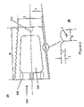
- FIG. 2 shows another embodiment of the subject implant that has a threaded outer surface and comprises a channel that provides a space to dispose biologically active substances.
- FIG. 2A shows a side view of this embodiment and FIG. 2B depicts a close-up of the threaded surface.
- FIG. 3 shows another embodiment of the subject implant that comprises an oval channel and whose threads are slightly modified compared to the threads shown in FIG. 2 .
- FIG. 3A shows a side view capturing the channel of the implant.
- FIG. 3B represents a close-up of the threads machined on the exterior of the implant.
- FIG. 3C represents an end-view of this embodiment.
- FIG. 3D shows a side-view of this embodiment that is rotated as to show the side walls of the implant adjacent to the channel.
- FIG. 4 shows a further embodiment of the subject implant that comprises a wedge-like end to aid in manipulating the implant.
- FIG. 4A shows a side view which depicts the channel and wedge-like end.
- FIG. 4B shows a perspective view of this embodiment.
- FIG. 4C shows an end-view of the wedge-like end.
- FIG. 4D shows a side view that is rotated as to show the side walls of the implant adjacent to the channel.
- FIG. 5 shows a further embodiment of the subject implant that tapers from one end to the other but has a region in the middle of the implant that is more narrow than either end.
- FIG. 6 shows a further embodiment of the subject implant that comprises a slot formed on the wider of the two ends.
- FIG. 6A is a perspective view of this embodiment.
- FIG. 6B is a side view of this embodiment.
- FIG. 6C is an end-view of the wider end of this embodiment.
- FIG. 7 shows an end-view ( FIGS. 7B–C ) and side view ( FIG. 7A ) of several drives for securing the subject implant into place.
- FIG. 8 shows side views ( FIGS. 8A–B ) and end view ( FIG. 8C ) of a further embodiment of the subject implant.
- FIG. 9 shows a further embodiment of the subject implant that comprises pinch cut out for engaging a securing device.
- FIG. 9A is a side view of an embodiment that has a channel and smooth exterior.
- FIG. 9B is an end view of the embodiment shown in FIG. 9A .
- FIG. 9C is a side view of the embodiment of FIG. 9A which has a threaded exterior surface.
- FIG. 10 shows a perspective view of another embodiment of the subject invention that comprises a number of separate pieces ( FIG. 10A ) that are assembled into a single unit ( FIG. 10B ).
- FIG. 11 shows a perspective view ( FIG. 11A ), an end-view ( FIG. 11B ), a cross-sectional view ( FIG. 11C ), and a side view ( FIG. 11D ) of another embodiment of the subject implant that is perforated to facilitate delivery of biologically active substances.
- FIG. 12 shows a perspective view ( FIG. 12A ), an end-view ( FIG. 12B ), a cross-sectional view ( FIG. 12C ), and a side-view ( FIG. 12D ) of an embodiment of the subject implant which is a variation of the embodiment shown in FIG. 11 .
- FIG. 13 depicts an example of a bone that is an appropriate source for deriving an implant having a wedge-like end.
- FIG. 14 represents a schematic for procuring a bone block from the bone depicted in FIG. 13 , which can then be machined to form an implant according to the teachings of the subject invention.
- FIGS. 1A–B show an example of a bone block 100 that is then tapered according to the teachings of the subject invention.
- the dashed lines A depict the tapering of the bone block, which can be accomplished by conventional machining methods, e.g., with a lathe and in particular, a CNC lathe.
- Holes 105 are drilled into the bone block via a drill to engage a securing device for positioning of the implant of the subject invention into the spine.
- 4 holes are drilled in a square configuration suitable for engaging a specially adapted securing device having four prongs for insertion into holes 105 .
- the subject implant is secured by rotation. See FIG. 1B .
- Machining attachment hole 110 is formed in the bone block 100 which provides a means for the block to be positioned in a machine such as a mill or lathe to hold the block steady during machining, to ensure proper alignment, and to permit rotation of the workpiece during machining.
- embodiment 200 comprises holes 205 for engaging a securing and driving device. Further, this embodiment comprises a channel 220 that preferably transverses completely through the implant. Channel 220 provides a space into which an osteogenic material can be disposed to aid in the healing and bone formation process. Also, the inventors have discovered that provision of the channel 220 aids in release of bone morphogenetic proteins (BMP) naturally present in the bone used for producing the subject implant and better contact of adjacent vertebrae with the osteogenic material within said dowel.
- BMP bone morphogenetic proteins
- Embodiment 200 also comprises a machining attachment hole 210 .
- Various dimensions of the implant are noted in FIGS. 2A–B , represented by the letters B–G. The skilled artisan will readily appreciate that these dimensions can be adapted to suit various sized patients, including infants, children, and adults. The following values are to be viewed as preferred values.
- Length B can range from about 5 to about 25 mm, and preferably from about 10 to about 15 mm.
- the root diameter C can range from about 3 to about 15 mm, and preferably from about 4 to about 11 mm.
- the taper angle D can range from about 1 to about 8 degrees, and preferably from about 3 to about 5 degrees.
- E can range from about 0.3 mm to about 1 mm, and preferably from about 0.4 mm to about 0.6 mm.
- the radius F of the thread profile can range from about 0.3 mm to about 1.3 mm, and preferably from about 0.5 mm to about 0.9 mm.
- the pitch G of the thread profile can range from about 0.08 to about 2 mm, and preferably from about 1 mm to about 1.8 mm.
- FIGS. 3A–D there is shown a further embodiment 300 of the subject implant that is similar to embodiment 200 except that the channel 320 is oval in shape and the thread profile is slightly modified.
- the oval shape of the channel 320 is achieved by drilling a circular hole through the implant, and then drawing an appropriately dimensioned broach through the circular hole.
- the broach has disposed thereon cutting teeth which change in shape as the diameter of the broach increases from a circular to an oval circumference.
- Embodiment 300 also comprises a machining attachment hole 310 .
- Dimension H comprises the length of the channel 320 which can range from about 4 to about 8 mm.
- FIG. 3B shows the thread profile comprising a ridge J, which can range from about 0.05 mm to about 0.15 mm. Further, embodiment 300 comprises a machining attachment hole 310 .
- FIGS. 4A–D show a further embodiment 400 of the subject implant which comprises oblique sides 415 thereby forming a “roof-top” or wedge-like shape on end 410 of the implant to engage a securing device, wherein the securing device is shaped to conform to end 410 .
- Embodiment 400 comprises a channel 420 .
- the dimensions noted in FIGS. 4A–D have the same values as above, unless otherwise indicated.
- Embodiment 400 comprises a substantially planar or flat end 425 having a dimension L toward which oblique sides 415 slope and connect. Dimension L preferably ranges from 0.5 to about 5 mm.
- a securing device hole 430 is formed into the wedge end which is designed to engage to a securing device to thereby further stabilize the implant on the securing and driver device during implantation.
- Dimensions M and N preferably range from about 0.5 mm to about 7 mm. More preferably, dimension N is equal to or larger than dimension M.
- Wedge angle P preferably ranges from about 45 to about 90 degrees, and preferably is set to a standard style angle to match a reciprocal angle on a driver tool.
- the tibia comprises an anterior ridge along a substantial portion of its length. It was found that excising block sections along such a ridge can provide oblique sides, thereby avoiding having to machine and discard precious bone material to produce such oblique sides, while preserving donor bone stock for other applications.
- the wedge shaped driving structure fits conveniently into a complementary driver device for rotation of the implant.
- a method of procuring the subject implant comprises obtaining a long bone, such as the tibia 1300 , and cutting off the ends 1310 and 1320 from the elongated central portion (dashed lines AA).
- FIG. 14 shows an end-view of the resulting central portion section produced after excision of the end portions 1310 and 1320 .
- sections (dashed lines BB) along the ridge 1340 of the tibia are excised which comprise a wedge end as a result of the natural architecture of the bone.
- Embodiment 500 also preferably comprises oblique sides 515 and a securing device hole 530 .
- FIGS. 6A–C there is shown another embodiment 600 of the subject implant having a slot 635 formed on the wider of the two ends of the implant.
- the slot 635 is designed to engage a securing and driving device, such as, for example, a flat-head screwdriver.
- embodiment 600 comprises a channel 620 and a securing device hole 630 .
- Dimensions B, D, H, and O shown in FIGS. 6A–C have similar values as described above.
- FIGS. 7A–D there are shown further embodiments of the subject implant that comprises a peg 705 contiguous with and extending from end 750 , the wider of the two ends of the implant.
- the peg acts as driver to turn and secure the implant when engaged to a securing device.
- the peg device may be round for being driven by a collet, or may be square or otherwise shaped for secure torquing by a reciprocal driving means.
- FIG. 7B shows an end-view of the narrower end 755 .
- FIGS. 7C and D show various alternatives for the shape of the peg, e.g., square and hexagonal. The skilled artisan will appreciate other appropriate shapes can be used, e.g. octagonal, triagonal, etc.
- the drive means may be recessed into the implant and driven by an appropriately shaped driver.
- FIGS. 8A–C there is shown another embodiment 800 of the subject implant that comprises both a wedge-like end 810 and a raised vertex 805 to further aid in engaging a securing device.
- Embodiment 800 comprises a securing device hole 830 as well.
- FIG. 8C shows an end-view of embodiment 800 showing the raised vertex 805 , securing device hole 830 , and the oblique sides 815 .
- the value of D is the same as that described above.
- the implant comprises a channel 820 .
- FIGS. 9A–C show a further embodiment 900 of the subject invention that comprises two or more pinch cut outs 905 from the edge of the wider of the two ends 950 of the implant.
- the pinch cut outs 905 act to engage a securing device for securing the implant in the patient.
- FIG. 9A shows a version of the embodiment 900 that does not have threads disposed on its surface.
- FIG. 9B shows an end-view of the wider end 950 , which depicts two pinch cut outs 905 positioned on opposing sides of the implant.
- FIG. 9C shows a threaded embodiment.
- FIG. 9D shows an embodiment that comprises a channel 920 and a narrower stepped portion 930 at its wider end 950 .
- the subject implant does not necessarily comprise threads. However, threads are preferred in most cases, as they aid in securing the implant in the patient. Rotation of the subject implant results in the threads digging into the adjacent bones thereby forming a tight contact.
- Embodiment 1000 comprises a first section 1004 and a second section 1005 that are placed contiguous to each other and then secured together by pins 1010 .
- the pins 1010 may be formed from any appropriate material, including but not limited to cortical bone, titanium, stainless steel, hydroxyapatite, bioactive glass, polylactic acid and like polymers.
- the second section has a slot 1015 formed thereon for engaging a securing device, as well as a securing device hole 1030 for further stabilization on the securing device during implantation.
- FIG. 10B shows the embodiment 1000 as assembled.
- FIG. 10B illustrates the formation of a channel 1020 when the implant is assembled.
- the second section 1005 comprising the slot 1015 could be configured to have formed thereon any of the other driver means described herein, e.g., wedge, raised ridge, peg, pinch, 4-pin, etc.
- FIG. 11A shows a perspective view of further embodiment 1100 of the subject implant, having a tapered body resulting in a smaller diameter for the front end 1110 , and a larger diameter for the back end 1120 .
- the back end 1120 comprises a hex drive 1130 formed therein for insertion and rotation of the implant.
- Implant 1100 defines a channel 1140 for use of packing biologically active substances. Holes 1150 , which radiate from the channel 1140 to the cortical surface 1160 , allow the biologically active substances to penetrate through the entire implant 1100 .
- FIG. 11B is an end plan view of implant 1100 showing the back end 1120 along with the hex drive 1130 .
- FIG. 11C depicts a transverse section of implant 1100 along the AA axis shown in FIG. 11B .
- the hex drive 1130 is shown running from the front end 1110 to the back end 1120 .
- FIG. 11D shows a side view of implant 1100 , holes 1150 , and screw threads 1170 which are inscribed from the front end 1110 to the back end 1120 .
- the screw threads 1170 ease insertion and help to hold the implant in place.
- FIGS. 12A–12D show an alternate embodiment of the cervical tapered dowel depicted in FIGS. 11A–11D .
- FIG. 12A shows a perspective view of implant 1200 , having a tapered body resulting in a smaller diameter for the front end 1210 and a larger diameter for the back end 1220 .
- the back end 1220 contains an instrument hole 1230 along with a score mark 1240 for use with an insertion device to provide torque to the implant.
- Implant 1200 contains a channel 1250 for packing biologically active substances along with holes 1260 that radiate from the channel 1250 to the cortical surface 1270 .
- FIG. 12B is an end plan view of implant 1200 showing back end 1220 along with the instrument hole 1230 and the score mark 1240 .
- FIG. 12C depicts a transverse section of implant 1200 along the AA axis shown in FIG. 12B .
- the instrument hole 1230 is shown extending partially through the implant into the channel 1250 .
- FIG. 12D shows a side view of implant 1200 .
- the screw threads 1280 ease insertion and help the implant retain its position once implanted.
- the implant may be contacted with cells prior to implantation.
- bone implants according to this invention may be cultured with stem cells, fibroblasts, muscle cells, neuronal cells or the like or simply contacted therewith or be infused therewith prior to implantation.
- the cells that are contacted with the implant are stem cells, such as those known in the art or which become known hereafter.
- stem cells such as those known in the art or which become known hereafter.
- human mesenchymal or other stem cells such as those disclosed in any of U.S. Pat. Nos.
- perforations or holes can be formed in the subject implants, which can control and improve the release and delivery of biologically active substances loaded in the channel, or otherwise infused, embedded or coated on or in the implants.
- the rate of release will be dependent on the size and number of holes provided.
- the channel of the subject dowels can be packed with various biologically active substances, including, but not limited to, growth factors, antibiotics, nucleic acids, proteins, peptides, antineoplastics, and anti-inflammatory compounds, and the like.
- the plurality of holes taught herein can facilitate the migration and growth of cells and tissues into the implant.
- any appropriate carrier may be used in association with these biologically active substances, including, but not limited to, gelatin, collagen, mixtures thereof, synthetic compositions, biologically resorbable pastes and the like.
- the composition may comprise a bone paste composition comprising cortical bone chips, cancellous bone chips, demineralized bone matrix powder (DBM), bioactive glass or other ceramics, growth factors, nucleic acids, proteins, peptides, carbohydrates, lipids and the like.
- the substance packed in the canal is an osteogenic substance and/or comprises tissue regenerating growth factors. See, for example, WO98/40113, herein incorporated by reference.
- the subject implants can be infused, soaked and/or coated with various biologically active substances.
- a cut dowel as described above was placed with the anterior end facing the tooling bit in the chuck of the machining lathe and tightened.
- the lathe motor was turned on and the end of the dowel was machined to form 3.5 mm oblique side on the end.
- a starter hole was drilled in the end of the dowel. This operation was repeated until all of the dowels were machined with the oblique side and had the starter hole drilled therein.
- each dowel was individually placed into the chuck with the posterior end of the dowel facing the tooling bit and tightened. The end of the dowel was machined until all the cancellous bone was removed and the dowel was flat. The dowel was then removed from the chuck and measured to determine if the length was at a desired length and to determine whether more bone needed to be removed. Using the center drill in the tail stock, a starter hole in the flattened end of the dowel was drilled. This procedure was repeated for all of the machined dowels. Next, the 3 mm drill bit was secured in the chuck in the tail-stock and tightened.
- a dowel with the 3.5 mm flat was placed in the chuck facing the drill bit and tightened.
- the tail-stock was advanced forward until the tip of the drill bit was about 1 mm from the end of the dowel and the tail-stock was tightened to the lathe bed.
- the motor was activated and the drill bit was advanced into the dowel to form a hole 6 mm in depth. This procedure was repeated for all of the dowels.
- the dowels having the oblique sides, flattened end and holes drilled on both ends were then subjected to the threading lathe.
- the dowel was placed in the threading lathe and tightened.
- the air motor was activated with the milling cutter attached and advanced into the dowel until lightly touching the dowel.
- the threading handle was turned to move the cutter assembly to the right until it cleared the dowel.
- the cutter was advanced forward to remove the desired amount of bone to achieve the desired dowel diameter.
- the foregoing procedure was repeated for all of the dowels. Using a burring tool or a scraper, any burrs present were removed from the dowel.
- a fine tooth brush was used to brush the threads on the dowel to remove any fine burrs.
Abstract
Description
Claims (7)
Priority Applications (3)
| Application Number | Priority Date | Filing Date | Title |
|---|---|---|---|
| US09/704,299 US7182781B1 (en) | 2000-03-02 | 2000-11-01 | Cervical tapered dowel |
| AU2001243280A AU2001243280A1 (en) | 2000-03-02 | 2001-02-26 | Cervical tapered dowel |
| PCT/US2001/006047 WO2001064141A1 (en) | 2000-03-02 | 2001-02-26 | Cervical tapered dowel |
Applications Claiming Priority (2)
| Application Number | Priority Date | Filing Date | Title |
|---|---|---|---|
| US18631200P | 2000-03-02 | 2000-03-02 | |
| US09/704,299 US7182781B1 (en) | 2000-03-02 | 2000-11-01 | Cervical tapered dowel |
Publications (1)
| Publication Number | Publication Date |
|---|---|
| US7182781B1 true US7182781B1 (en) | 2007-02-27 |
Family
ID=26881966
Family Applications (1)
| Application Number | Title | Priority Date | Filing Date |
|---|---|---|---|
| US09/704,299 Expired - Fee Related US7182781B1 (en) | 2000-03-02 | 2000-11-01 | Cervical tapered dowel |
Country Status (3)
| Country | Link |
|---|---|
| US (1) | US7182781B1 (en) |
| AU (1) | AU2001243280A1 (en) |
| WO (1) | WO2001064141A1 (en) |
Cited By (25)
| Publication number | Priority date | Publication date | Assignee | Title |
|---|---|---|---|---|
| US20030023304A1 (en) * | 2000-01-11 | 2003-01-30 | Carter Kevin C. | Materials and methods for improved bone tendon bone transplantation |
| US20040230303A1 (en) * | 2003-05-16 | 2004-11-18 | Gomes Katherine A. | Cartilage allograft plug |
| US20060195095A1 (en) * | 2003-03-24 | 2006-08-31 | Theken Surgical, Llc | Spinal implant adjustment |
| US20060210643A1 (en) * | 2003-04-29 | 2006-09-21 | Truncale Katherine A G | Cartilage repair mixture containing allograft chondrocytes |
| US20060276907A1 (en) * | 2000-03-22 | 2006-12-07 | Boyer Michael L Ii | Multipiece implants formed of bone material |
| US20070009610A1 (en) * | 2005-07-11 | 2007-01-11 | Carina Syring | Engineered osteochondral construct for treatment of articular cartilage defects |
| US20070028710A1 (en) * | 2003-05-14 | 2007-02-08 | Kilian Kraus | Height-adjustable implant to be inserted between vertebral bodies and corresponding handling tool |
| US20070233145A1 (en) * | 2005-08-18 | 2007-10-04 | Biocomposites Ltd. | Tensegrity osteotomy system |
| US20080220044A1 (en) * | 2007-03-06 | 2008-09-11 | Semler Eric J | Cancellous construct with support ring for repair of osteochondral defects |
| US20090043389A1 (en) * | 2004-04-02 | 2009-02-12 | Gordana Vunjak-Novakovic | Cartilage implant plug with fibrin glue and method for implantation |
| US20090149893A1 (en) * | 2007-12-05 | 2009-06-11 | Semler Eric J | Cancellous Bone Implant for Cartilage Repair |
| US20090291112A1 (en) * | 2003-05-16 | 2009-11-26 | Truncale Katherine G | Allograft osteochondral plug combined with cartilage particle mixture |
| US20090319045A1 (en) * | 2004-10-12 | 2009-12-24 | Truncale Katherine G | Cancellous constructs, cartilage particles and combinations of cancellous constructs and cartilage particles |
| US20100015202A1 (en) * | 2007-03-06 | 2010-01-21 | Semler Eric J | Cancellous construct with support ring for repair of osteochondral defects |
| US20100274362A1 (en) * | 2009-01-15 | 2010-10-28 | Avner Yayon | Cartilage particle tissue mixtures optionally combined with a cancellous construct |
| US7837740B2 (en) | 2007-01-24 | 2010-11-23 | Musculoskeletal Transplant Foundation | Two piece cancellous construct for cartilage repair |
| US7837735B2 (en) | 2000-12-14 | 2010-11-23 | Depuy Spine, Inc. | Devices and methods for facilitating controlled bone growth or repair |
| US7909870B2 (en) | 2003-12-11 | 2011-03-22 | Tpl - Kilian Kraus | Height-adjustable spinal implant and operating instrument for the implant |
| US20110160864A1 (en) * | 2001-05-03 | 2011-06-30 | Dominique Messerli | Intervertebral implant for transforaminal posterior lumbar interbody fusion procedure |
| US8920511B2 (en) | 2011-11-17 | 2014-12-30 | Allosource | Multi-piece machine graft systems and methods |
| US9381048B2 (en) | 2011-08-31 | 2016-07-05 | DePuy Synthes Products, Inc. | Devices and methods for cervical lateral fixation |
| US9615913B2 (en) | 2000-01-11 | 2017-04-11 | RTI Surgical, Inc | Materials and methods for improved bone tendon bone transplantation |
| US9701940B2 (en) | 2005-09-19 | 2017-07-11 | Histogenics Corporation | Cell-support matrix having narrowly defined uniformly vertically and non-randomly organized porosity and pore density and a method for preparation thereof |
| US10077420B2 (en) | 2014-12-02 | 2018-09-18 | Histogenics Corporation | Cell and tissue culture container |
| US11744624B2 (en) * | 2017-08-14 | 2023-09-05 | Surgebright Gmbh | Bone screw |
Families Citing this family (3)
| Publication number | Priority date | Publication date | Assignee | Title |
|---|---|---|---|---|
| DE10152567A1 (en) * | 2001-10-24 | 2003-05-08 | Tutogen Medical Gmbh | implant |
| US7008226B2 (en) * | 2002-08-23 | 2006-03-07 | Woodwelding Ag | Implant, in particular a dental implant |
| WO2006107302A1 (en) * | 2005-04-04 | 2006-10-12 | Zimmer Spine, Inc. | Threaded intervertebral implant |
Citations (39)
| Publication number | Priority date | Publication date | Assignee | Title |
|---|---|---|---|---|
| DE3505567A1 (en) | 1984-11-30 | 1986-06-05 | José Manuel Otero Dr. Vigo Pontevedra Vich | Screw-type surgical implant for cervical bones |
| US4721096A (en) | 1986-04-18 | 1988-01-26 | Marrow-Tech Incorporated | Process for replicating bone marrow in vitro and using the same |
| US4878915A (en) * | 1987-01-22 | 1989-11-07 | Brantigan John W | Surgical prosthetic implant facilitating vertebral interbody fusion |
| US4963489A (en) | 1987-04-14 | 1990-10-16 | Marrow-Tech, Inc. | Three-dimensional cell and tissue culture system |
| EP0517030A2 (en) | 1991-06-04 | 1992-12-09 | MAN Ceramics GmbH | Vertebral implant |
| US5197985A (en) | 1990-11-16 | 1993-03-30 | Caplan Arnold I | Method for enhancing the implantation and differentiation of marrow-derived mesenchymal cells |
| US5486359A (en) | 1990-11-16 | 1996-01-23 | Osiris Therapeutics, Inc. | Human mesenchymal stem cells |
| EP0734703A2 (en) | 1995-03-27 | 1996-10-02 | Danek Medical, Inc. | Interbody fusion device and method for restoration of normal spinal anatomy |
| WO1996040019A1 (en) | 1995-06-07 | 1996-12-19 | Michelson Gary K | Frusto-conical interbody spinal fusion implants |
| US5591625A (en) | 1993-11-24 | 1997-01-07 | Case Western Reserve University | Transduced mesenchymal stem cells |
| US5593409A (en) * | 1988-06-13 | 1997-01-14 | Sofamor Danek Group, Inc. | Interbody spinal fusion implants |
| US5609636A (en) * | 1994-05-23 | 1997-03-11 | Spine-Tech, Inc. | Spinal implant |
| US5609635A (en) | 1988-06-28 | 1997-03-11 | Michelson; Gary K. | Lordotic interbody spinal fusion implants |
| WO1997025945A1 (en) | 1996-01-16 | 1997-07-24 | University Of Florida, Tissue Bank, Inc. | Diaphysial cortical dowel |
| US5733542A (en) | 1990-11-16 | 1998-03-31 | Haynesworth; Stephen E. | Enhancing bone marrow engraftment using MSCS |
| US5736396A (en) | 1995-01-24 | 1998-04-07 | Case Western Reserve University | Lineage-directed induction of human mesenchymal stem cell differentiation |
| WO1998038924A2 (en) | 1997-03-06 | 1998-09-11 | Sulzer Spine-Tech, Inc. | Lordotic spinal implant |
| WO1998040113A1 (en) | 1997-03-13 | 1998-09-17 | University Of Florida Tissue Bank, Inc. | Bone paste |
| US5811094A (en) | 1990-11-16 | 1998-09-22 | Osiris Therapeutics, Inc. | Connective tissue regeneration using human mesenchymal stem cell preparations |
| US5827735A (en) | 1992-06-22 | 1998-10-27 | Morphogen Pharmaceuticals, Inc. | Pluripotent mesenchymal stem cells and methods of use thereof |
| WO1999009914A1 (en) | 1997-08-27 | 1999-03-04 | University Of Florida Tissue Bank, Inc. | Cortical bone cervical smith-robinson fusion implant |
| US5902741A (en) | 1986-04-18 | 1999-05-11 | Advanced Tissue Sciences, Inc. | Three-dimensional cartilage cultures |
| US5906934A (en) | 1995-03-14 | 1999-05-25 | Morphogen Pharmaceuticals, Inc. | Mesenchymal stem cells for cartilage repair |
| US5906616A (en) * | 1994-09-15 | 1999-05-25 | Surgical Dynamics, Inc. | Conically shaped anterior fusion cage and method of implantation |
| US5908784A (en) | 1995-11-16 | 1999-06-01 | Case Western Reserve University | In vitro chondrogenic induction of human mesenchymal stem cells |
| US5942255A (en) | 1996-07-15 | 1999-08-24 | The University Of Memphis | Methods of enhancing lean tissue mass and bone mineral content and compositions therefor |
| US5951560A (en) | 1997-10-15 | 1999-09-14 | Applied Biological Concepts, Inc. | Wedge orthopedic screw |
| US6102948A (en) * | 1996-01-16 | 2000-08-15 | Surgical Dynamics Inc. | Spinal fusion device |
| US6111164A (en) * | 1996-06-21 | 2000-08-29 | Musculoskeletal Transplant Foundation | Bone graft insert |
| US6174311B1 (en) * | 1998-10-28 | 2001-01-16 | Sdgi Holdings, Inc. | Interbody fusion grafts and instrumentation |
| US6200347B1 (en) * | 1999-01-05 | 2001-03-13 | Lifenet | Composite bone graft, method of making and using same |
| US6210412B1 (en) * | 1988-06-13 | 2001-04-03 | Gary Karlin Michelson | Method for inserting frusto-conical interbody spinal fusion implants |
| US6258125B1 (en) * | 1998-08-03 | 2001-07-10 | Synthes (U.S.A.) | Intervertebral allograft spacer |
| US6261586B1 (en) * | 1997-06-11 | 2001-07-17 | Sdgi Holdings, Inc. | Bone graft composites and spacers |
| US6277149B1 (en) * | 1999-06-08 | 2001-08-21 | Osteotech, Inc. | Ramp-shaped intervertebral implant |
| US6494883B1 (en) * | 2000-05-26 | 2002-12-17 | Bret A. Ferree | Bone reinforcers |
| US6527805B2 (en) * | 1999-12-15 | 2003-03-04 | Sulzer Orthopedics Ltd | Intervertebral implant |
| US6558423B1 (en) * | 1999-05-05 | 2003-05-06 | Gary K. Michelson | Interbody spinal fusion implants with multi-lock for locking opposed screws |
| US6652584B2 (en) * | 2000-02-04 | 2003-11-25 | Gary K. Michelson | Expandable threaded arcuate interbody spinal fusion implant with lordotic configuration during insertion |
-
2000
- 2000-11-01 US US09/704,299 patent/US7182781B1/en not_active Expired - Fee Related
-
2001
- 2001-02-26 WO PCT/US2001/006047 patent/WO2001064141A1/en active Application Filing
- 2001-02-26 AU AU2001243280A patent/AU2001243280A1/en not_active Abandoned
Patent Citations (45)
| Publication number | Priority date | Publication date | Assignee | Title |
|---|---|---|---|---|
| DE3505567A1 (en) | 1984-11-30 | 1986-06-05 | José Manuel Otero Dr. Vigo Pontevedra Vich | Screw-type surgical implant for cervical bones |
| US5962325A (en) | 1986-04-18 | 1999-10-05 | Advanced Tissue Sciences, Inc. | Three-dimensional stromal tissue cultures |
| US4721096A (en) | 1986-04-18 | 1988-01-26 | Marrow-Tech Incorporated | Process for replicating bone marrow in vitro and using the same |
| US5902741A (en) | 1986-04-18 | 1999-05-11 | Advanced Tissue Sciences, Inc. | Three-dimensional cartilage cultures |
| US4878915A (en) * | 1987-01-22 | 1989-11-07 | Brantigan John W | Surgical prosthetic implant facilitating vertebral interbody fusion |
| US4963489A (en) | 1987-04-14 | 1990-10-16 | Marrow-Tech, Inc. | Three-dimensional cell and tissue culture system |
| US5593409A (en) * | 1988-06-13 | 1997-01-14 | Sofamor Danek Group, Inc. | Interbody spinal fusion implants |
| US6210412B1 (en) * | 1988-06-13 | 2001-04-03 | Gary Karlin Michelson | Method for inserting frusto-conical interbody spinal fusion implants |
| US5609635A (en) | 1988-06-28 | 1997-03-11 | Michelson; Gary K. | Lordotic interbody spinal fusion implants |
| US5486359A (en) | 1990-11-16 | 1996-01-23 | Osiris Therapeutics, Inc. | Human mesenchymal stem cells |
| US5197985A (en) | 1990-11-16 | 1993-03-30 | Caplan Arnold I | Method for enhancing the implantation and differentiation of marrow-derived mesenchymal cells |
| US5811094A (en) | 1990-11-16 | 1998-09-22 | Osiris Therapeutics, Inc. | Connective tissue regeneration using human mesenchymal stem cell preparations |
| US5733542A (en) | 1990-11-16 | 1998-03-31 | Haynesworth; Stephen E. | Enhancing bone marrow engraftment using MSCS |
| EP0517030A2 (en) | 1991-06-04 | 1992-12-09 | MAN Ceramics GmbH | Vertebral implant |
| US5827735A (en) | 1992-06-22 | 1998-10-27 | Morphogen Pharmaceuticals, Inc. | Pluripotent mesenchymal stem cells and methods of use thereof |
| US5591625A (en) | 1993-11-24 | 1997-01-07 | Case Western Reserve University | Transduced mesenchymal stem cells |
| US5609636A (en) * | 1994-05-23 | 1997-03-11 | Spine-Tech, Inc. | Spinal implant |
| US5906616A (en) * | 1994-09-15 | 1999-05-25 | Surgical Dynamics, Inc. | Conically shaped anterior fusion cage and method of implantation |
| US5736396A (en) | 1995-01-24 | 1998-04-07 | Case Western Reserve University | Lineage-directed induction of human mesenchymal stem cell differentiation |
| US5906934A (en) | 1995-03-14 | 1999-05-25 | Morphogen Pharmaceuticals, Inc. | Mesenchymal stem cells for cartilage repair |
| EP0734703A2 (en) | 1995-03-27 | 1996-10-02 | Danek Medical, Inc. | Interbody fusion device and method for restoration of normal spinal anatomy |
| US5782919A (en) | 1995-03-27 | 1998-07-21 | Sdgi Holdings, Inc. | Interbody fusion device and method for restoration of normal spinal anatomy |
| US5669909A (en) | 1995-03-27 | 1997-09-23 | Danek Medical, Inc. | Interbody fusion device and method for restoration of normal spinal anatomy |
| WO1996040019A1 (en) | 1995-06-07 | 1996-12-19 | Michelson Gary K | Frusto-conical interbody spinal fusion implants |
| US5908784A (en) | 1995-11-16 | 1999-06-01 | Case Western Reserve University | In vitro chondrogenic induction of human mesenchymal stem cells |
| US6102948A (en) * | 1996-01-16 | 2000-08-15 | Surgical Dynamics Inc. | Spinal fusion device |
| WO1997025945A1 (en) | 1996-01-16 | 1997-07-24 | University Of Florida, Tissue Bank, Inc. | Diaphysial cortical dowel |
| US5814084A (en) * | 1996-01-16 | 1998-09-29 | University Of Florida Tissue Bank, Inc. | Diaphysial cortical dowel |
| US6111164A (en) * | 1996-06-21 | 2000-08-29 | Musculoskeletal Transplant Foundation | Bone graft insert |
| US5942255A (en) | 1996-07-15 | 1999-08-24 | The University Of Memphis | Methods of enhancing lean tissue mass and bone mineral content and compositions therefor |
| US6165219A (en) * | 1997-03-06 | 2000-12-26 | Sulzer Spine-Tech Inc. | Lordotic spinal implant |
| WO1998038924A2 (en) | 1997-03-06 | 1998-09-11 | Sulzer Spine-Tech, Inc. | Lordotic spinal implant |
| WO1998040113A1 (en) | 1997-03-13 | 1998-09-17 | University Of Florida Tissue Bank, Inc. | Bone paste |
| US6261586B1 (en) * | 1997-06-11 | 2001-07-17 | Sdgi Holdings, Inc. | Bone graft composites and spacers |
| WO1999009914A1 (en) | 1997-08-27 | 1999-03-04 | University Of Florida Tissue Bank, Inc. | Cortical bone cervical smith-robinson fusion implant |
| US5951560A (en) | 1997-10-15 | 1999-09-14 | Applied Biological Concepts, Inc. | Wedge orthopedic screw |
| US6258125B1 (en) * | 1998-08-03 | 2001-07-10 | Synthes (U.S.A.) | Intervertebral allograft spacer |
| US6174311B1 (en) * | 1998-10-28 | 2001-01-16 | Sdgi Holdings, Inc. | Interbody fusion grafts and instrumentation |
| US6200347B1 (en) * | 1999-01-05 | 2001-03-13 | Lifenet | Composite bone graft, method of making and using same |
| US6458158B1 (en) * | 1999-01-05 | 2002-10-01 | Lifenet | Composite bone graft, method of making and using same |
| US6558423B1 (en) * | 1999-05-05 | 2003-05-06 | Gary K. Michelson | Interbody spinal fusion implants with multi-lock for locking opposed screws |
| US6277149B1 (en) * | 1999-06-08 | 2001-08-21 | Osteotech, Inc. | Ramp-shaped intervertebral implant |
| US6527805B2 (en) * | 1999-12-15 | 2003-03-04 | Sulzer Orthopedics Ltd | Intervertebral implant |
| US6652584B2 (en) * | 2000-02-04 | 2003-11-25 | Gary K. Michelson | Expandable threaded arcuate interbody spinal fusion implant with lordotic configuration during insertion |
| US6494883B1 (en) * | 2000-05-26 | 2002-12-17 | Bret A. Ferree | Bone reinforcers |
Cited By (51)
| Publication number | Priority date | Publication date | Assignee | Title |
|---|---|---|---|---|
| US10188505B2 (en) | 2000-01-11 | 2019-01-29 | Rti Surgical, Inc. | Materials and methods for improved bone tendon bone transplantation |
| US20030023304A1 (en) * | 2000-01-11 | 2003-01-30 | Carter Kevin C. | Materials and methods for improved bone tendon bone transplantation |
| US9615913B2 (en) | 2000-01-11 | 2017-04-11 | RTI Surgical, Inc | Materials and methods for improved bone tendon bone transplantation |
| US20060276907A1 (en) * | 2000-03-22 | 2006-12-07 | Boyer Michael L Ii | Multipiece implants formed of bone material |
| US8142503B2 (en) | 2000-12-14 | 2012-03-27 | Depuy Spine, Inc. | Devices and methods for facilitating controlled bone growth or repair |
| US8906093B2 (en) | 2000-12-14 | 2014-12-09 | DePuy Synthes Products, LLC | Devices and methods for facilitating controlled bone growth or repair |
| US7837735B2 (en) | 2000-12-14 | 2010-11-23 | Depuy Spine, Inc. | Devices and methods for facilitating controlled bone growth or repair |
| US8617246B2 (en) | 2000-12-14 | 2013-12-31 | Depuy Spine, Inc. | Devices and methods for facilitating controlled bone growth or repair |
| US8523908B2 (en) | 2000-12-14 | 2013-09-03 | Depuy Synthes Products Llc | Devices and methods for facilitating controlled bone growth or repair |
| US8690949B2 (en) | 2001-05-03 | 2014-04-08 | DePuy Synthes Products, LLC | Intervertebral implant for transforaminal posterior lumbar interbody fusion procedure |
| US8435300B2 (en) * | 2001-05-03 | 2013-05-07 | DePuy Synthes Products, LLC | Intervertebral implant for transforaminal posterior lumbar interbody fusion procedure |
| US20110160864A1 (en) * | 2001-05-03 | 2011-06-30 | Dominique Messerli | Intervertebral implant for transforaminal posterior lumbar interbody fusion procedure |
| USRE46647E1 (en) | 2001-05-03 | 2017-12-26 | DePuy Synthes Products, Inc. | Intervertebral implant for transforaminal posterior lumbar interbody fusion procedure |
| US7918876B2 (en) | 2003-03-24 | 2011-04-05 | Theken Spine, Llc | Spinal implant adjustment device |
| US20060217712A1 (en) * | 2003-03-24 | 2006-09-28 | Richard Mueller | Spinal implant adjustment device |
| US20060195095A1 (en) * | 2003-03-24 | 2006-08-31 | Theken Surgical, Llc | Spinal implant adjustment |
| USRE42208E1 (en) | 2003-04-29 | 2011-03-08 | Musculoskeletal Transplant Foundation | Glue for cartilage repair |
| US20080133008A1 (en) * | 2003-04-29 | 2008-06-05 | Muscuoskeletal Transplant Foundation | Cartilage repair mixture containing allograft chondrocytes |
| US20060210643A1 (en) * | 2003-04-29 | 2006-09-21 | Truncale Katherine A G | Cartilage repair mixture containing allograft chondrocytes |
| USRE43258E1 (en) | 2003-04-29 | 2012-03-20 | Musculoskeletal Transplant Foundation | Glue for cartilage repair |
| US20070028710A1 (en) * | 2003-05-14 | 2007-02-08 | Kilian Kraus | Height-adjustable implant to be inserted between vertebral bodies and corresponding handling tool |
| US8568482B2 (en) | 2003-05-14 | 2013-10-29 | Kilian Kraus | Height-adjustable implant to be inserted between vertebral bodies and corresponding handling tool |
| US20090291112A1 (en) * | 2003-05-16 | 2009-11-26 | Truncale Katherine G | Allograft osteochondral plug combined with cartilage particle mixture |
| US8221500B2 (en) | 2003-05-16 | 2012-07-17 | Musculoskeletal Transplant Foundation | Cartilage allograft plug |
| US20090069901A1 (en) * | 2003-05-16 | 2009-03-12 | Katherine Gomes Truncale | Cartilage allograft plug |
| US20040230303A1 (en) * | 2003-05-16 | 2004-11-18 | Gomes Katherine A. | Cartilage allograft plug |
| US7901457B2 (en) | 2003-05-16 | 2011-03-08 | Musculoskeletal Transplant Foundation | Cartilage allograft plug |
| US8267998B2 (en) | 2003-12-11 | 2012-09-18 | Kilian Kraus | Operating instrument for a height-adjustable spinal implant |
| US7909870B2 (en) | 2003-12-11 | 2011-03-22 | Tpl - Kilian Kraus | Height-adjustable spinal implant and operating instrument for the implant |
| US20090043389A1 (en) * | 2004-04-02 | 2009-02-12 | Gordana Vunjak-Novakovic | Cartilage implant plug with fibrin glue and method for implantation |
| US8292968B2 (en) | 2004-10-12 | 2012-10-23 | Musculoskeletal Transplant Foundation | Cancellous constructs, cartilage particles and combinations of cancellous constructs and cartilage particles |
| US20090319045A1 (en) * | 2004-10-12 | 2009-12-24 | Truncale Katherine G | Cancellous constructs, cartilage particles and combinations of cancellous constructs and cartilage particles |
| US7815926B2 (en) | 2005-07-11 | 2010-10-19 | Musculoskeletal Transplant Foundation | Implant for articular cartilage repair |
| US20070009610A1 (en) * | 2005-07-11 | 2007-01-11 | Carina Syring | Engineered osteochondral construct for treatment of articular cartilage defects |
| US20070233145A1 (en) * | 2005-08-18 | 2007-10-04 | Biocomposites Ltd. | Tensegrity osteotomy system |
| US9701940B2 (en) | 2005-09-19 | 2017-07-11 | Histogenics Corporation | Cell-support matrix having narrowly defined uniformly vertically and non-randomly organized porosity and pore density and a method for preparation thereof |
| US7837740B2 (en) | 2007-01-24 | 2010-11-23 | Musculoskeletal Transplant Foundation | Two piece cancellous construct for cartilage repair |
| US8906110B2 (en) | 2007-01-24 | 2014-12-09 | Musculoskeletal Transplant Foundation | Two piece cancellous construct for cartilage repair |
| US8435551B2 (en) | 2007-03-06 | 2013-05-07 | Musculoskeletal Transplant Foundation | Cancellous construct with support ring for repair of osteochondral defects |
| US20080220044A1 (en) * | 2007-03-06 | 2008-09-11 | Semler Eric J | Cancellous construct with support ring for repair of osteochondral defects |
| US20100015202A1 (en) * | 2007-03-06 | 2010-01-21 | Semler Eric J | Cancellous construct with support ring for repair of osteochondral defects |
| US20090149893A1 (en) * | 2007-12-05 | 2009-06-11 | Semler Eric J | Cancellous Bone Implant for Cartilage Repair |
| US20100274362A1 (en) * | 2009-01-15 | 2010-10-28 | Avner Yayon | Cartilage particle tissue mixtures optionally combined with a cancellous construct |
| US9381048B2 (en) | 2011-08-31 | 2016-07-05 | DePuy Synthes Products, Inc. | Devices and methods for cervical lateral fixation |
| US9724132B2 (en) | 2011-08-31 | 2017-08-08 | DePuy Synthes Products, Inc. | Devices and methods for cervical lateral fixation |
| US10376380B2 (en) | 2011-08-31 | 2019-08-13 | DePuy Synthes Products, Inc. | Devices and methods for cervical lateral fixation |
| US8920511B2 (en) | 2011-11-17 | 2014-12-30 | Allosource | Multi-piece machine graft systems and methods |
| US9364328B2 (en) | 2011-11-17 | 2016-06-14 | Allosource | Multi-piece machine graft systems and methods |
| US10077420B2 (en) | 2014-12-02 | 2018-09-18 | Histogenics Corporation | Cell and tissue culture container |
| US11555172B2 (en) | 2014-12-02 | 2023-01-17 | Ocugen, Inc. | Cell and tissue culture container |
| US11744624B2 (en) * | 2017-08-14 | 2023-09-05 | Surgebright Gmbh | Bone screw |
Also Published As
| Publication number | Publication date |
|---|---|
| WO2001064141A1 (en) | 2001-09-07 |
| AU2001243280A1 (en) | 2001-09-12 |
Similar Documents
| Publication | Publication Date | Title |
|---|---|---|
| US7182781B1 (en) | Cervical tapered dowel | |
| US7553313B2 (en) | Apparatus and method for preparing a spinal implant surgical site for receiving a spinal fusion implant | |
| US7048765B1 (en) | Intervertebral spacers | |
| US7048762B1 (en) | Elongated cortical bone implant | |
| JP4156197B2 (en) | Composite intervertebral spacer | |
| US11471203B2 (en) | Apparatus, system and method for fusion of bone | |
| US6210412B1 (en) | Method for inserting frusto-conical interbody spinal fusion implants | |
| AU746640B2 (en) | Open intervertebral spacer | |
| CA2238117C (en) | Method and instrumentation for implant insertion | |
| US20020138143A1 (en) | Cortical bone cervical Smith-Robinson fusion implant | |
| JP4159255B2 (en) | Spinal fixation implant | |
| US6042582A (en) | Instrumentation and method for facilitating insertion of spinal implant | |
| US6315795B1 (en) | Fusion implant device and method of use | |
| US8291572B2 (en) | Multi-component cortical bone assembled implant | |
| US20020038123A1 (en) | Osteotomy implant | |
| JP4388051B2 (en) | Cortical cervical spine Smith-Robinson fusion implant | |
| WO2002009597A2 (en) | Diaphysial cortical dowel | |
| US20040193174A1 (en) | Spinal implant and driver tool | |
| KR20010024069A (en) | Fusion implant device and method of use | |
| WO2001080753A2 (en) | Cortical bone interference screw | |
| Grooms | Cortical bone-based composite implants |
Legal Events
| Date | Code | Title | Description |
|---|---|---|---|
| AS | Assignment |
Owner name: REGENERATION TECHNOLOGIES, INC., FLORIDA Free format text: ASSIGNMENT OF ASSIGNORS INTEREST;ASSIGNORS:BIANCHI, JOHN R.;CARTER, KEVIN C.;REEL/FRAME:011630/0776;SIGNING DATES FROM 20010226 TO 20010307 |
|
| AS | Assignment |
Owner name: MERRILL LYNCH BUSINESS FINANCIAL SERVICES, INC., T Free format text: SECURITY AGREEMENT;ASSIGNORS:REGENERATION TECHNOLOGIES, INC.;ALABAMA TISSUE CENTER, INC.;RTI SERVICES, INC.;AND OTHERS;REEL/FRAME:015116/0841 Effective date: 20040323 |
|
| AS | Assignment |
Owner name: REGENERATION TECHNOLOGIES, INC., FLORIDA Free format text: ASSIGNMENT OF ASSIGNORS INTEREST;ASSIGNORS:SOUTHEAST TISSUE ALLIANCE, INC.;UNIVERSITY OF FLORIDA ORTHOPAEDIC TISSUE BANK, INC.;UNIVERSITY OF FLORIDA TISSUE BANK, INC.;REEL/FRAME:015796/0186 Effective date: 20050121 Owner name: REGENERATION TECHNOLOGIES, INC.,FLORIDA Free format text: ASSIGNMENT OF ASSIGNORS INTEREST;ASSIGNORS:SOUTHEAST TISSUE ALLIANCE, INC.;UNIVERSITY OF FLORIDA ORTHOPAEDIC TISSUE BANK, INC.;UNIVERSITY OF FLORIDA TISSUE BANK, INC.;REEL/FRAME:015796/0186 Effective date: 20050121 |
|
| AS | Assignment |
Owner name: REGENERATION TECHNOLOGIES, INC., FLORIDA Free format text: ASSIGNMENT OF ASSIGNORS INTEREST;ASSIGNOR:REGENERATION TECHNOLOGIES, INC.;REEL/FRAME:016646/0873 Effective date: 20050805 |
|
| STCF | Information on status: patent grant |
Free format text: PATENTED CASE |
|
| AS | Assignment |
Owner name: RTI BIOLOGICS, INC., FLORIDA Free format text: CHANGE OF NAME;ASSIGNOR:REGENERATION TECHNOLOGIES, INC.;REEL/FRAME:020690/0942 Effective date: 20080227 Owner name: RTI BIOLOGICS, INC.,FLORIDA Free format text: CHANGE OF NAME;ASSIGNOR:REGENERATION TECHNOLOGIES, INC.;REEL/FRAME:020690/0942 Effective date: 20080227 |
|
| AS | Assignment |
Owner name: REGENERATION TECHNOLOGIES, INC.-CARDIOVASCULAR (F/ Free format text: RECORD OF RELEASE OF SECURITY INTEREST;ASSIGNOR:GE BUSINESS FINANCIAL SERVICES INC.;REEL/FRAME:022151/0633 Effective date: 20081230 Owner name: RTI BIOLOGICS, INC. (F/K/A) REGENERATION TECHNOLOG Free format text: RECORD OF RELEASE OF SECURITY INTEREST;ASSIGNOR:GE BUSINESS FINANCIAL SERVICES INC.;REEL/FRAME:022151/0633 Effective date: 20081230 Owner name: RTI SERVICES, INC., FLORIDA Free format text: RECORD OF RELEASE OF SECURITY INTEREST;ASSIGNOR:GE BUSINESS FINANCIAL SERVICES INC.;REEL/FRAME:022151/0633 Effective date: 20081230 Owner name: BIOLOGICAL RECOVERY GROUP, INC., FLORIDA Free format text: RECORD OF RELEASE OF SECURITY INTEREST;ASSIGNOR:GE BUSINESS FINANCIAL SERVICES INC.;REEL/FRAME:022151/0633 Effective date: 20081230 |
|
| FEPP | Fee payment procedure |
Free format text: PAT HOLDER NO LONGER CLAIMS SMALL ENTITY STATUS, ENTITY STATUS SET TO UNDISCOUNTED (ORIGINAL EVENT CODE: STOL); ENTITY STATUS OF PATENT OWNER: LARGE ENTITY |
|
| FPAY | Fee payment |
Year of fee payment: 4 |
|
| AS | Assignment |
Owner name: TD BANK, N.A., AS ADMINISTRATIVE AGENT, FLORIDA Free format text: SECURITY AGREEMENT;ASSIGNOR:RTI SURGICAL, INC.;REEL/FRAME:030888/0001 Effective date: 20130716 |
|
| AS | Assignment |
Owner name: RTI SURGICAL, INC., FLORIDA Free format text: CHANGE OF NAME;ASSIGNOR:RTI BIOLOGICS, INC.;REEL/FRAME:031012/0159 Effective date: 20130716 |
|
| FPAY | Fee payment |
Year of fee payment: 8 |
|
| AS | Assignment |
Owner name: TD BANK, N.A., NEW JERSEY Free format text: SECURITY INTEREST;ASSIGNOR:RTI SURGICAL, INC.;REEL/FRAME:043608/0874 Effective date: 20170718 |
|
| AS | Assignment |
Owner name: JPMORGAN CHASE BANK, N.A., AS THE ADMINISTRATIVE AGENT, ILLINOIS Free format text: SECURITY INTEREST;ASSIGNORS:RTI SURGICAL, INC.;PIONEER SURGICAL TECHNOLOGY, INC.;TUTOGEN MEDICAL, INC.;REEL/FRAME:046303/0926 Effective date: 20180605 Owner name: JPMORGAN CHASE BANK, N.A., AS THE ADMINISTRATIVE A Free format text: SECURITY INTEREST;ASSIGNORS:RTI SURGICAL, INC.;PIONEER SURGICAL TECHNOLOGY, INC.;TUTOGEN MEDICAL, INC.;REEL/FRAME:046303/0926 Effective date: 20180605 |
|
| AS | Assignment |
Owner name: RTI SURGICAL, INC., FLORIDA Free format text: RELEASE BY SECURED PARTY;ASSIGNOR:TD BANK, N.A., AS ADMINISTRATIVE AGENT;REEL/FRAME:046327/0184 Effective date: 20180605 Owner name: RTI SURGICAL, INC., FLORIDA Free format text: RELEASE BY SECURED PARTY;ASSIGNOR:TD BANK, N.A., AS ADMINISTRATIVE AGENT;REEL/FRAME:046327/0864 Effective date: 20180605 |
|
| FEPP | Fee payment procedure |
Free format text: MAINTENANCE FEE REMINDER MAILED (ORIGINAL EVENT CODE: REM.); ENTITY STATUS OF PATENT OWNER: LARGE ENTITY |
|
| AS | Assignment |
Owner name: ARES CAPITAL CORPORATION, AS ADMINISTRATIVE AGENT, Free format text: SECURITY INTEREST;ASSIGNORS:RTI SURGICAL, INC.;PIONEER SURGICAL TECHNOLOGY, INC.;TUTOGEN MEDICAL, INC.;AND OTHERS;REEL/FRAME:048543/0505 Effective date: 20190308 Owner name: ARES CAPITAL CORPORATION, AS ADMINISTRATIVE AGENT, NEW YORK Free format text: SECURITY INTEREST;ASSIGNORS:RTI SURGICAL, INC.;PIONEER SURGICAL TECHNOLOGY, INC.;TUTOGEN MEDICAL, INC.;AND OTHERS;REEL/FRAME:048543/0505 Effective date: 20190308 |
|
| LAPS | Lapse for failure to pay maintenance fees |
Free format text: PATENT EXPIRED FOR FAILURE TO PAY MAINTENANCE FEES (ORIGINAL EVENT CODE: EXP.); ENTITY STATUS OF PATENT OWNER: LARGE ENTITY |
|
| STCH | Information on status: patent discontinuation |
Free format text: PATENT EXPIRED DUE TO NONPAYMENT OF MAINTENANCE FEES UNDER 37 CFR 1.362 |
|
| FP | Lapsed due to failure to pay maintenance fee |
Effective date: 20190227 |
|
| AS | Assignment |
Owner name: FOURTH DIMENSION SPINE, LLC, NEW YORK Free format text: RELEASE BY SECURED PARTY;ASSIGNOR:ARES CAPITAL CORPORATION, AS AGENT;REEL/FRAME:053257/0652 Effective date: 20200720 Owner name: RTI SURGICAL, INC., FLORIDA Free format text: RELEASE BY SECURED PARTY;ASSIGNOR:ARES CAPITAL CORPORATION, AS AGENT;REEL/FRAME:053257/0652 Effective date: 20200720 Owner name: TUTOGEN MEDICAL, INC., FLORIDA Free format text: RELEASE BY SECURED PARTY;ASSIGNOR:ARES CAPITAL CORPORATION, AS AGENT;REEL/FRAME:053257/0652 Effective date: 20200720 Owner name: PARADIGM SPINE, LLC, NEW YORK Free format text: RELEASE BY SECURED PARTY;ASSIGNOR:ARES CAPITAL CORPORATION, AS AGENT;REEL/FRAME:053257/0652 Effective date: 20200720 Owner name: PIONEER SURGICAL TECHNOLOGY, INC., FLORIDA Free format text: RELEASE BY SECURED PARTY;ASSIGNOR:ARES CAPITAL CORPORATION, AS AGENT;REEL/FRAME:053257/0652 Effective date: 20200720 |
|
| AS | Assignment |
Owner name: PIONEER SURGICAL TECHNOLOGY, INC., FLORIDA Free format text: RELEASE BY SECURED PARTY;ASSIGNOR:JPMORGAN CHASE BANK, N.A., AS ADMINISTRATIVE AGENT;REEL/FRAME:053260/0398 Effective date: 20200720 Owner name: TUTOGEN MEDICAL, INC., FLORIDA Free format text: RELEASE BY SECURED PARTY;ASSIGNOR:JPMORGAN CHASE BANK, N.A., AS ADMINISTRATIVE AGENT;REEL/FRAME:053260/0398 Effective date: 20200720 Owner name: RTI SURGICAL, INC., FLORIDA Free format text: RELEASE BY SECURED PARTY;ASSIGNOR:JPMORGAN CHASE BANK, N.A., AS ADMINISTRATIVE AGENT;REEL/FRAME:053260/0398 Effective date: 20200720 |