US7088219B2 - Method for remote vehicle ignition enablement and disablement via broadband enabled security mechanisms - Google Patents
Method for remote vehicle ignition enablement and disablement via broadband enabled security mechanisms Download PDFInfo
- Publication number
- US7088219B2 US7088219B2 US10/759,937 US75993704A US7088219B2 US 7088219 B2 US7088219 B2 US 7088219B2 US 75993704 A US75993704 A US 75993704A US 7088219 B2 US7088219 B2 US 7088219B2
- Authority
- US
- United States
- Prior art keywords
- condition
- vehicle
- enablement
- ignition
- receiving
- Prior art date
- Legal status (The legal status is an assumption and is not a legal conclusion. Google has not performed a legal analysis and makes no representation as to the accuracy of the status listed.)
- Active, expires
Links
Images


Classifications
-
- B—PERFORMING OPERATIONS; TRANSPORTING
- B60—VEHICLES IN GENERAL
- B60R—VEHICLES, VEHICLE FITTINGS, OR VEHICLE PARTS, NOT OTHERWISE PROVIDED FOR
- B60R25/00—Fittings or systems for preventing or indicating unauthorised use or theft of vehicles
- B60R25/20—Means to switch the anti-theft system on or off
- B60R25/24—Means to switch the anti-theft system on or off using electronic identifiers containing a code not memorised by the user
- B60R25/241—Means to switch the anti-theft system on or off using electronic identifiers containing a code not memorised by the user whereby access privileges are related to the identifiers
-
- B—PERFORMING OPERATIONS; TRANSPORTING
- B60—VEHICLES IN GENERAL
- B60R—VEHICLES, VEHICLE FITTINGS, OR VEHICLE PARTS, NOT OTHERWISE PROVIDED FOR
- B60R25/00—Fittings or systems for preventing or indicating unauthorised use or theft of vehicles
- B60R25/01—Fittings or systems for preventing or indicating unauthorised use or theft of vehicles operating on vehicle systems or fittings, e.g. on doors, seats or windscreens
- B60R25/04—Fittings or systems for preventing or indicating unauthorised use or theft of vehicles operating on vehicle systems or fittings, e.g. on doors, seats or windscreens operating on the propulsion system, e.g. engine or drive motor
-
- B—PERFORMING OPERATIONS; TRANSPORTING
- B60—VEHICLES IN GENERAL
- B60R—VEHICLES, VEHICLE FITTINGS, OR VEHICLE PARTS, NOT OTHERWISE PROVIDED FOR
- B60R25/00—Fittings or systems for preventing or indicating unauthorised use or theft of vehicles
- B60R25/20—Means to switch the anti-theft system on or off
- B60R25/2009—Antitheft state indicator
-
- B—PERFORMING OPERATIONS; TRANSPORTING
- B60—VEHICLES IN GENERAL
- B60R—VEHICLES, VEHICLE FITTINGS, OR VEHICLE PARTS, NOT OTHERWISE PROVIDED FOR
- B60R2325/00—Indexing scheme relating to vehicle anti-theft devices
- B60R2325/20—Communication devices for vehicle anti-theft devices
- B60R2325/202—Personal digital assistant [PDA]
-
- B—PERFORMING OPERATIONS; TRANSPORTING
- B60—VEHICLES IN GENERAL
- B60R—VEHICLES, VEHICLE FITTINGS, OR VEHICLE PARTS, NOT OTHERWISE PROVIDED FOR
- B60R2325/00—Indexing scheme relating to vehicle anti-theft devices
- B60R2325/20—Communication devices for vehicle anti-theft devices
- B60R2325/205—Mobile phones
Definitions
- the present invention relates generally to vehicle enablement and disablement and, more particularly, to remotely controlling vehicle ignition enablement and disablement through various wireless technologies.
- On Star® and LoJack® are examples of systems used to track stolen vehicles. Each of these two systems utilize a patch antenna on a vehicle to transmit and receive signals from a Global Positioning System (GPS) satellite. These services not only can provide detection of a location of a stolen vehicle, but can also allow for remote access to the vehicle if the keys are locked inside.
- GPS Global Positioning System
- Interactive theft deterrent systems typically though, do not connect to the ignition system of a vehicle.
- the present invention provides a method and computer program for remotely controlling vehicle ignition. At least one condition for disablement is received. Also, a vehicle ignition switch is disabled.
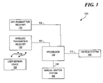
- FIG. 1 is a block diagram depicting the vehicle ignition computer
- FIG. 2 is a block diagram depicting the communication system for a vehicle.
- the reference numeral 100 generally designates a block diagram depicting the vehicle ignition computer.
- the ignition computer 100 comprises a GPS Transmitter/Receiver 110 , a wireless transmitter/receiver 120 , a processor 130 , a manual ignition system 140 , an ignition system 160 , and a user defined usage 150 .
- a user or owner can define specific parameters under which the vehicle can operate, thereby allowing the user or owner to maintain overall control of the vehicle without the need to be physically with the vehicle. For example, if a parent is out of town, the parent can remotely define a specific time and geographical area under which a child can operate the vehicle.
- the ignition computer 100 utilizes a logical AND function. In other words, in terms of Boolean algebra, the user defined usage 150 and the manual ignition system 140 must both be TRUE.
- the proactive mode can either be enabled or disabled based on user desire, geography, time of allowed usage and so forth. Examples of a particular enablement or disablement are the so-called “safe zones” and “unsafe zones.” An owner or user can predefine certain geographical regions in which the manual ignition switch would function therein without the need for a predefined usage. In other words, a key would turn the engine over in a safe zone.
- the processor can also be equipped to effectively be trained and to learn where safe and unsafe zones are located based on history.
- the processor 130 can crosscheck and historically compare the GPS-provided coordinates, the alarm system, and any other sensors that the car is equipped with to detect any potentially harmful scenarios. Essentially the computer can “learn” what zones are safe zones and anticipate potential unsafe zones.
- the proactive mode there are a variety of other features that can be realized.
- No attempt to re-enable the vehicle using the manual ignition system 140 can cause the processor to reactivate the ignition system 160 .
- the owner of the vehicle can “check up” on the vehicle by utilizing one of the wireless/broadband access technologies that utilize the wireless transmitter/receiver 120 . To accomplish this, the owner calls the vehicle and authenticates using a private key. Once authenticated, the owner contacts the vehicle and asks for status. For example, if the vehicle processor is configured to utilize a cellular network, the owner can “dial” the vehicle. The vehicle can reply with a variety of responses, such as a longitude and latitude.
- a “disable” signal is sent securely over one of the transport mediums to the vehicle, such as a satellite uplink.
- the vehicle can be stopped when it is safe to do so and allows for either silent mode disabling, where the driver of the vehicle is not notified, or non-silent where a warning message can be communicated to the driver of the impending stop.
- Law enforcement can have a database linking license plates, car Vehicle Identification Numbers (VINs), and so forth for an embedded code needed to send to the vehicle to make it stop. That way, any law enforcement vehicle can stop a vehicle fitted with a disablement system. Conversely, the database could proactively notify a law enforcement vehicle when in proximity of the suspect VIN number via message broadcast to the law enforcement vehicle.
- the processor 130 is coupled to the GPS transmitter/receiver 110 through a first communications channel 102 .
- the processor 130 is also coupled to the wireless transmitter/receiver 120 through a second communications channel 104 .
- the processor 130 is coupled to the manual ignition system 140 through a third communications channel 106 .
- the processor is also coupled to the ignition system 160 through a fourth communications channel 112 .
- the user defined usage 150 is coupled to the wireless transmitter/receiver 120 through a first wireless communications channel 108 .
- any of the aforementioned communication channels would encompass wireless links, optical links, conductor cable links, packet switched channels, direct communication channels, and any combination thereof.
- the reference numeral 200 generally designates the communication system for a vehicle.
- the communication system 200 comprises a vehicle 214 , a wireless phone interface 208 , a pager interface 206 , a satellite interface 210 , a radio/microwave interface 212 , a computer network 204 , and an owner/user 202 .
- an owner/user 202 can remotely enable as described in FIG. 1 .
- the user/owner 202 is coupled to the computer network 204 through a fifth communications channel 220 .
- the computer network 204 is coupled to the wireless phone interface 208 through a sixth communications channel 222 .
- the computer network 204 is also connected to the pager interface 206 through a seventh communications channel 224 .
- the computer network 204 is also coupled to the other wireless communications interface 216 through an eighth communication channel 226 .
- the computer network 204 is also coupled to the satellite interface 110 through a ninth communications channel 228 .
- the computer network 204 is also coupled to the radio/microwave interface 212 through a tenth communications channel 230 .
- the wireless phone interface 208 is coupled to the vehicle 214 through an eleventh communications channel 232 .
- the pager interface 206 is coupled to the vehicle 214 through a twelfth communications channel 234 .
- the other wireless communications interface 216 is coupled to the vehicle 214 through a thirteenth communications channel 236 .
- the satellite interface 210 is coupled to the vehicle 214 through a fourteenth communications channel 238 .
- the radio/microwave interface 212 is coupled to the vehicle 214 through a fifteenth communications channel 240 .
- the computer network can be any type of computer network including, but not limited to, the Internet.
- any of the aforementioned communications channels would encompass wireless links, optical links, conductor cable links, packet switched channels, direct communication channels, and any combination thereof.
Abstract
Description
Claims (20)
Priority Applications (1)
| Application Number | Priority Date | Filing Date | Title |
|---|---|---|---|
| US10/759,937 US7088219B2 (en) | 2004-01-16 | 2004-01-16 | Method for remote vehicle ignition enablement and disablement via broadband enabled security mechanisms |
Applications Claiming Priority (1)
| Application Number | Priority Date | Filing Date | Title |
|---|---|---|---|
| US10/759,937 US7088219B2 (en) | 2004-01-16 | 2004-01-16 | Method for remote vehicle ignition enablement and disablement via broadband enabled security mechanisms |
Publications (2)
| Publication Number | Publication Date |
|---|---|
| US20050156706A1 US20050156706A1 (en) | 2005-07-21 |
| US7088219B2 true US7088219B2 (en) | 2006-08-08 |
Family
ID=34749805
Family Applications (1)
| Application Number | Title | Priority Date | Filing Date |
|---|---|---|---|
| US10/759,937 Active 2024-10-14 US7088219B2 (en) | 2004-01-16 | 2004-01-16 | Method for remote vehicle ignition enablement and disablement via broadband enabled security mechanisms |
Country Status (1)
| Country | Link |
|---|---|
| US (1) | US7088219B2 (en) |
Cited By (13)
| Publication number | Priority date | Publication date | Assignee | Title |
|---|---|---|---|---|
| US20050082913A1 (en) * | 2003-10-20 | 2005-04-21 | Hiroaki Nomura | Vehicle antitheft system |
| US20070200663A1 (en) * | 2006-02-13 | 2007-08-30 | Steve White | Method and system for controlling a vehicle given to a third party |
| US20070239992A1 (en) * | 2006-02-13 | 2007-10-11 | Steve White | Method and system for preventing unauthorized use of a vehicle by an operator of the vehicle |
| US20090085731A1 (en) * | 2007-10-01 | 2009-04-02 | Honda R&D America, Inc. | Vehicle Disabling System and Process |
| DE102009005613A1 (en) * | 2009-01-22 | 2010-06-24 | Continental Automotive Gmbh | Arrangement for control of vehicle functions, has module or tracking module formed to prevent execution of vehicle functions when examination of validity of identification indicates invalid identification |
| US7825782B2 (en) | 2007-03-20 | 2010-11-02 | Ford Global Technologies, Llc | Device and method for wireless vehicle communication |
| US9047494B1 (en) * | 2008-09-08 | 2015-06-02 | United Services Automobile Association | System and method for disabling and/or enabling a device |
| US9168893B1 (en) | 2014-04-22 | 2015-10-27 | Ituran Usa | System, method, and appartus for remotely disabling or enabling a vehicle |
| US9880186B2 (en) | 2014-09-29 | 2018-01-30 | Laird Technologies, Inc. | Telematics devices and methods for vehicle speeding detection |
| US10019771B2 (en) | 2013-10-24 | 2018-07-10 | General Motors Llc | Method and system for enabling after-hours vehicle pick up |
| US10155498B2 (en) | 2015-08-05 | 2018-12-18 | Frederick Howroyd | Remote vehicle disabling system and method |
| DE102017010059A1 (en) | 2017-10-27 | 2019-05-02 | Giesecke+Devrient Mobile Security Gmbh | System and method for authenticating a person to start a vehicle |
| US20220063556A1 (en) * | 2018-12-21 | 2022-03-03 | Volkswagen Aktiengesellschaft | Method for Deactivating a Motor Vehicle, Deactivation System for a Motor Vehicle, and Motor Vehicle |
Families Citing this family (6)
| Publication number | Priority date | Publication date | Assignee | Title |
|---|---|---|---|---|
| GB2439955A (en) * | 2006-07-11 | 2008-01-16 | Ian Christopher Aviet | Motor vehicle safety unit using mobile telephone signals |
| US20090091419A1 (en) * | 2007-10-08 | 2009-04-09 | Gm Global Technology Operations, Inc. | Methods and systems to control remote access to a vehicle module |
| US20090143878A1 (en) * | 2007-12-04 | 2009-06-04 | Caterpillar Inc. | Operator profile control system for a machine |
| US9311616B2 (en) * | 2010-06-14 | 2016-04-12 | On-Board Communications, Inc. | System and method for determining equipment utilization changes based on ignition and motion status |
| EP2666138A4 (en) * | 2011-01-17 | 2014-08-06 | Imetrik Technologies Inc | Computer-implemented method and system for reporting a confidence score in relation to a vehicle equipped with a wireless-enabled usage reporting device |
| US9811247B2 (en) * | 2013-11-25 | 2017-11-07 | Lg Electronics Inc. | In-vehicle infotainment device and image display method using the same |
Citations (10)
| Publication number | Priority date | Publication date | Assignee | Title |
|---|---|---|---|---|
| US5276728A (en) * | 1991-11-06 | 1994-01-04 | Kenneth Pagliaroli | Remotely activated automobile disabling system |
| US5805057A (en) * | 1997-11-05 | 1998-09-08 | Eslaminovin; Firooz B. | Remote vehicle disabling and distress indicator system |
| US5874889A (en) * | 1997-01-09 | 1999-02-23 | Roadtrac Llc | System and methods for triggering and transmitting vehicle alarms to a central monitoring station |
| US5918180A (en) * | 1995-12-22 | 1999-06-29 | Dimino; Michael | Telephone operable global tracking system for vehicles |
| US6011321A (en) * | 1998-05-11 | 2000-01-04 | Stancu; Dumitru V | Page receiver security system |
| US6028537A (en) * | 1996-06-14 | 2000-02-22 | Prince Corporation | Vehicle communication and remote control system |
| US6275773B1 (en) * | 1993-08-11 | 2001-08-14 | Jerome H. Lemelson | GPS vehicle collision avoidance warning and control system and method |
| US6664888B1 (en) * | 1997-12-16 | 2003-12-16 | Vetronix Telematics Llc | Method and apparatus for enabling and disabling certain functions of an automobile |
| US6900723B2 (en) * | 2000-08-15 | 2005-05-31 | Pioneer Corporation | Anti-theft system for vehicles |
| US6924728B2 (en) * | 2001-05-14 | 2005-08-02 | No-Start Inc. | Safety feature for vehicles parked indoors |
-
2004
- 2004-01-16 US US10/759,937 patent/US7088219B2/en active Active
Patent Citations (10)
| Publication number | Priority date | Publication date | Assignee | Title |
|---|---|---|---|---|
| US5276728A (en) * | 1991-11-06 | 1994-01-04 | Kenneth Pagliaroli | Remotely activated automobile disabling system |
| US6275773B1 (en) * | 1993-08-11 | 2001-08-14 | Jerome H. Lemelson | GPS vehicle collision avoidance warning and control system and method |
| US5918180A (en) * | 1995-12-22 | 1999-06-29 | Dimino; Michael | Telephone operable global tracking system for vehicles |
| US6028537A (en) * | 1996-06-14 | 2000-02-22 | Prince Corporation | Vehicle communication and remote control system |
| US5874889A (en) * | 1997-01-09 | 1999-02-23 | Roadtrac Llc | System and methods for triggering and transmitting vehicle alarms to a central monitoring station |
| US5805057A (en) * | 1997-11-05 | 1998-09-08 | Eslaminovin; Firooz B. | Remote vehicle disabling and distress indicator system |
| US6664888B1 (en) * | 1997-12-16 | 2003-12-16 | Vetronix Telematics Llc | Method and apparatus for enabling and disabling certain functions of an automobile |
| US6011321A (en) * | 1998-05-11 | 2000-01-04 | Stancu; Dumitru V | Page receiver security system |
| US6900723B2 (en) * | 2000-08-15 | 2005-05-31 | Pioneer Corporation | Anti-theft system for vehicles |
| US6924728B2 (en) * | 2001-05-14 | 2005-08-02 | No-Start Inc. | Safety feature for vehicles parked indoors |
Cited By (23)
| Publication number | Priority date | Publication date | Assignee | Title |
|---|---|---|---|---|
| US20050082913A1 (en) * | 2003-10-20 | 2005-04-21 | Hiroaki Nomura | Vehicle antitheft system |
| US20070200663A1 (en) * | 2006-02-13 | 2007-08-30 | Steve White | Method and system for controlling a vehicle given to a third party |
| US20070239992A1 (en) * | 2006-02-13 | 2007-10-11 | Steve White | Method and system for preventing unauthorized use of a vehicle by an operator of the vehicle |
| US8549318B2 (en) | 2006-02-13 | 2013-10-01 | Affirmed Technologies, Llc | Method and system for preventing unauthorized use of a vehicle by an operator of the vehicle |
| US20100152976A1 (en) * | 2006-02-13 | 2010-06-17 | All Protect, Lllc | Method and system for controlling a vehicle given to a third party |
| US7956730B2 (en) | 2006-02-13 | 2011-06-07 | All Protect, Llc | Method and system for controlling a vehicle given to a third party |
| US7812712B2 (en) * | 2006-02-13 | 2010-10-12 | All Protect, Llc | Method and system for controlling a vehicle given to a third party |
| US20110015809A1 (en) * | 2007-03-20 | 2011-01-20 | Ford Global Technologies, Llc | Device and Method for Wireless Vehicle Communication |
| US7825782B2 (en) | 2007-03-20 | 2010-11-02 | Ford Global Technologies, Llc | Device and method for wireless vehicle communication |
| US20090085731A1 (en) * | 2007-10-01 | 2009-04-02 | Honda R&D America, Inc. | Vehicle Disabling System and Process |
| US7760076B2 (en) | 2007-10-01 | 2010-07-20 | Honda Motor Co., Ltd. | Vehicle disabling system and process |
| US10425394B1 (en) | 2008-09-08 | 2019-09-24 | United Services Automobile Association (Usaa) | System and method for disabling and/or enabling a device |
| US9047494B1 (en) * | 2008-09-08 | 2015-06-02 | United Services Automobile Association | System and method for disabling and/or enabling a device |
| DE102009005613A1 (en) * | 2009-01-22 | 2010-06-24 | Continental Automotive Gmbh | Arrangement for control of vehicle functions, has module or tracking module formed to prevent execution of vehicle functions when examination of validity of identification indicates invalid identification |
| US10019771B2 (en) | 2013-10-24 | 2018-07-10 | General Motors Llc | Method and system for enabling after-hours vehicle pick up |
| US9688245B2 (en) | 2014-04-22 | 2017-06-27 | Ituran Usa | System, method, and appartus for remotely disabling or enabling a vehicle |
| US9168893B1 (en) | 2014-04-22 | 2015-10-27 | Ituran Usa | System, method, and appartus for remotely disabling or enabling a vehicle |
| US9880186B2 (en) | 2014-09-29 | 2018-01-30 | Laird Technologies, Inc. | Telematics devices and methods for vehicle speeding detection |
| US9934622B2 (en) | 2014-09-29 | 2018-04-03 | Laird Technologies, Inc. | Telematics devices and methods for vehicle ignition detection |
| US10155498B2 (en) | 2015-08-05 | 2018-12-18 | Frederick Howroyd | Remote vehicle disabling system and method |
| DE102017010059A1 (en) | 2017-10-27 | 2019-05-02 | Giesecke+Devrient Mobile Security Gmbh | System and method for authenticating a person to start a vehicle |
| US20220063556A1 (en) * | 2018-12-21 | 2022-03-03 | Volkswagen Aktiengesellschaft | Method for Deactivating a Motor Vehicle, Deactivation System for a Motor Vehicle, and Motor Vehicle |
| US11872954B2 (en) * | 2018-12-21 | 2024-01-16 | Volkswagen Aktiengesellschaft | Method for deactivating a motor vehicle, deactivation system for a motor vehicle, and motor vehicle |
Also Published As
| Publication number | Publication date |
|---|---|
| US20050156706A1 (en) | 2005-07-21 |
Similar Documents
| Publication | Publication Date | Title |
|---|---|---|
| US7088219B2 (en) | Method for remote vehicle ignition enablement and disablement via broadband enabled security mechanisms | |
| CN103164892B (en) | Access road controls and monitoring system | |
| US5986543A (en) | Programmable vehicle monitoring and security system having multiple access verification devices | |
| US6731195B2 (en) | Tamper-resistant theft deterrent method and system | |
| KR100586467B1 (en) | Vehicle security system | |
| CA1277400C (en) | Anti-theft and locating system | |
| EP1564690B1 (en) | Security control system for managing registration of ID codes for portable devices | |
| US20040021550A1 (en) | Electronic key system | |
| JP5082729B2 (en) | Wireless device, control method thereof, and program | |
| US20080012693A1 (en) | Vehicle communication system | |
| CN102656829B (en) | For detecting equipment and the method for communication interference | |
| US20050116816A1 (en) | Vehicle theft protection system, a method of protecting a vehicle from theft, a vehicle-onboard device, a management station, and a program for protecting a vehicle from theft | |
| US8798855B2 (en) | System and method for self-detecting vehicle theft | |
| KR101745443B1 (en) | Authentication system for driver of vehicle | |
| US20050231335A1 (en) | Vehicle alarm remote paging system | |
| WO2005112276A2 (en) | Vehicle anti-theft entry system | |
| JP2004502061A (en) | Method and apparatus for controlling a parking space shut-off device for a vehicle | |
| CN101445095A (en) | Anti-theft alarming method of an on-line automobile and alarm system thereof | |
| Alli et al. | Design and Construction of a remotely controlled vehicle anti-theft system via GSM network | |
| JP2004237814A (en) | Electronic license plate recognizing system | |
| JP3994702B2 (en) | Vehicle control device, vehicle control method, vehicle control program, and computer-readable recording medium recording the same | |
| JP2001010448A (en) | Wireless method and device for preventing theft of vehicle | |
| JPH11170981A (en) | Method for discovering and alarming vehicle theft, and its device | |
| JP2003044989A (en) | Method and device for providing vehicle position information, program for controlling the vehicle position information providing device, and storage medium with the program recorded thereon | |
| KR20040003766A (en) | Automotive anti theft device with telematics device |
Legal Events
| Date | Code | Title | Description |
|---|---|---|---|
| AS | Assignment |
Owner name: INTERNATIONAL BUSINESS MACHINES CORPORATION, NEW Y Free format text: ASSIGNMENT OF ASSIGNORS INTEREST;ASSIGNORS:DAWSON, CHRISTOPHER JAMES;FELLENSTEIN, CRAIG WILLIAM;HAMILTON, RICK ALLEN;AND OTHERS;REEL/FRAME:014909/0882;SIGNING DATES FROM 20031205 TO 20031212 |
|
| FEPP | Fee payment procedure |
Free format text: PAYOR NUMBER ASSIGNED (ORIGINAL EVENT CODE: ASPN); ENTITY STATUS OF PATENT OWNER: LARGE ENTITY |
|
| STCF | Information on status: patent grant |
Free format text: PATENTED CASE |
|
| FPAY | Fee payment |
Year of fee payment: 4 |
|
| REMI | Maintenance fee reminder mailed | ||
| FPAY | Fee payment |
Year of fee payment: 8 |
|
| SULP | Surcharge for late payment |
Year of fee payment: 7 |
|
| MAFP | Maintenance fee payment |
Free format text: PAYMENT OF MAINTENANCE FEE, 12TH YEAR, LARGE ENTITY (ORIGINAL EVENT CODE: M1553) Year of fee payment: 12 |
|
| AS | Assignment |
Owner name: DAEDALUS GROUP LLC, NEW YORK Free format text: ASSIGNMENT OF ASSIGNORS INTEREST;ASSIGNOR:INTERNATIONAL BUSINESS MACHINES CORPORATION;REEL/FRAME:051032/0784 Effective date: 20190930 |
|
| AS | Assignment |
Owner name: DAEDALUS GROUP, LLC, NEW YORK Free format text: ASSIGNMENT OF ASSIGNORS INTEREST;ASSIGNOR:INTERNATIONAL BUSINESS MACHINES CORPORATION;REEL/FRAME:051710/0445 Effective date: 20191230 |
|
| AS | Assignment |
Owner name: SLINGSHOT IOT LLC, MARYLAND Free format text: ASSIGNMENT OF ASSIGNORS INTEREST;ASSIGNOR:DAEDALUS GROUP, LLC;REEL/FRAME:051733/0463 Effective date: 20200129 |