US6655488B2 - Gearbox, particularly for automotive vehicle with telescopic load-carrying arm - Google Patents
Gearbox, particularly for automotive vehicle with telescopic load-carrying arm Download PDFInfo
- Publication number
- US6655488B2 US6655488B2 US09/971,636 US97163601A US6655488B2 US 6655488 B2 US6655488 B2 US 6655488B2 US 97163601 A US97163601 A US 97163601A US 6655488 B2 US6655488 B2 US 6655488B2
- Authority
- US
- United States
- Prior art keywords
- shaft
- gearbox
- drive
- shaft line
- toothed
- Prior art date
- Legal status (The legal status is an assumption and is not a legal conclusion. Google has not performed a legal analysis and makes no representation as to the accuracy of the status listed.)
- Expired - Lifetime, expires
Links
- 230000005540 biological transmission Effects 0.000 claims abstract description 31
- 238000002485 combustion reaction Methods 0.000 claims abstract description 7
- 230000002706 hydrostatic effect Effects 0.000 claims abstract description 6
- 230000009471 action Effects 0.000 claims description 4
- 230000000694 effects Effects 0.000 description 4
- 230000004048 modification Effects 0.000 description 3
- 238000012986 modification Methods 0.000 description 3
- 238000010276 construction Methods 0.000 description 2
- 230000008901 benefit Effects 0.000 description 1
- 230000008859 change Effects 0.000 description 1
- 230000008878 coupling Effects 0.000 description 1
- 238000010168 coupling process Methods 0.000 description 1
- 238000005859 coupling reaction Methods 0.000 description 1
- 239000007788 liquid Substances 0.000 description 1
- 230000001050 lubricating effect Effects 0.000 description 1
- 238000004519 manufacturing process Methods 0.000 description 1
- 230000009347 mechanical transmission Effects 0.000 description 1
- 238000000034 method Methods 0.000 description 1
- 230000009467 reduction Effects 0.000 description 1
- 230000000153 supplemental effect Effects 0.000 description 1
- 230000001360 synchronised effect Effects 0.000 description 1
Images


Classifications
-
- B—PERFORMING OPERATIONS; TRANSPORTING
- B60—VEHICLES IN GENERAL
- B60K—ARRANGEMENT OR MOUNTING OF PROPULSION UNITS OR OF TRANSMISSIONS IN VEHICLES; ARRANGEMENT OR MOUNTING OF PLURAL DIVERSE PRIME-MOVERS IN VEHICLES; AUXILIARY DRIVES FOR VEHICLES; INSTRUMENTATION OR DASHBOARDS FOR VEHICLES; ARRANGEMENTS IN CONNECTION WITH COOLING, AIR INTAKE, GAS EXHAUST OR FUEL SUPPLY OF PROPULSION UNITS IN VEHICLES
- B60K17/00—Arrangement or mounting of transmissions in vehicles
- B60K17/28—Arrangement or mounting of transmissions in vehicles characterised by arrangement, location, or type of power take-off
-
- F—MECHANICAL ENGINEERING; LIGHTING; HEATING; WEAPONS; BLASTING
- F16—ENGINEERING ELEMENTS AND UNITS; GENERAL MEASURES FOR PRODUCING AND MAINTAINING EFFECTIVE FUNCTIONING OF MACHINES OR INSTALLATIONS; THERMAL INSULATION IN GENERAL
- F16H—GEARING
- F16H3/00—Toothed gearings for conveying rotary motion with variable gear ratio or for reversing rotary motion
- F16H3/02—Toothed gearings for conveying rotary motion with variable gear ratio or for reversing rotary motion without gears having orbital motion
- F16H3/08—Toothed gearings for conveying rotary motion with variable gear ratio or for reversing rotary motion without gears having orbital motion exclusively or essentially with continuously meshing gears, that can be disengaged from their shafts
- F16H3/087—Toothed gearings for conveying rotary motion with variable gear ratio or for reversing rotary motion without gears having orbital motion exclusively or essentially with continuously meshing gears, that can be disengaged from their shafts characterised by the disposition of the gears
-
- F—MECHANICAL ENGINEERING; LIGHTING; HEATING; WEAPONS; BLASTING
- F16—ENGINEERING ELEMENTS AND UNITS; GENERAL MEASURES FOR PRODUCING AND MAINTAINING EFFECTIVE FUNCTIONING OF MACHINES OR INSTALLATIONS; THERMAL INSULATION IN GENERAL
- F16H—GEARING
- F16H2200/00—Transmissions for multiple ratios
- F16H2200/003—Transmissions for multiple ratios characterised by the number of forward speeds
- F16H2200/0043—Transmissions for multiple ratios characterised by the number of forward speeds the gear ratios comprising four forward speeds
-
- F—MECHANICAL ENGINEERING; LIGHTING; HEATING; WEAPONS; BLASTING
- F16—ENGINEERING ELEMENTS AND UNITS; GENERAL MEASURES FOR PRODUCING AND MAINTAINING EFFECTIVE FUNCTIONING OF MACHINES OR INSTALLATIONS; THERMAL INSULATION IN GENERAL
- F16H—GEARING
- F16H2200/00—Transmissions for multiple ratios
- F16H2200/0082—Transmissions for multiple ratios characterised by the number of reverse speeds
- F16H2200/0091—Transmissions for multiple ratios characterised by the number of reverse speeds the gear ratios comprising three reverse speeds
-
- F—MECHANICAL ENGINEERING; LIGHTING; HEATING; WEAPONS; BLASTING
- F16—ENGINEERING ELEMENTS AND UNITS; GENERAL MEASURES FOR PRODUCING AND MAINTAINING EFFECTIVE FUNCTIONING OF MACHINES OR INSTALLATIONS; THERMAL INSULATION IN GENERAL
- F16H—GEARING
- F16H3/00—Toothed gearings for conveying rotary motion with variable gear ratio or for reversing rotary motion
- F16H3/02—Toothed gearings for conveying rotary motion with variable gear ratio or for reversing rotary motion without gears having orbital motion
- F16H3/08—Toothed gearings for conveying rotary motion with variable gear ratio or for reversing rotary motion without gears having orbital motion exclusively or essentially with continuously meshing gears, that can be disengaged from their shafts
- F16H3/14—Gearings for reversal only
- F16H3/145—Gearings for reversal only with a pair of coaxial bevel gears, rotatable in opposite directions
-
- Y—GENERAL TAGGING OF NEW TECHNOLOGICAL DEVELOPMENTS; GENERAL TAGGING OF CROSS-SECTIONAL TECHNOLOGIES SPANNING OVER SEVERAL SECTIONS OF THE IPC; TECHNICAL SUBJECTS COVERED BY FORMER USPC CROSS-REFERENCE ART COLLECTIONS [XRACs] AND DIGESTS
- Y10—TECHNICAL SUBJECTS COVERED BY FORMER USPC
- Y10T—TECHNICAL SUBJECTS COVERED BY FORMER US CLASSIFICATION
- Y10T74/00—Machine element or mechanism
- Y10T74/19—Gearing
- Y10T74/19023—Plural power paths to and/or from gearing
- Y10T74/19074—Single drive plural driven
- Y10T74/19079—Parallel
- Y10T74/19084—Spur
-
- Y—GENERAL TAGGING OF NEW TECHNOLOGICAL DEVELOPMENTS; GENERAL TAGGING OF CROSS-SECTIONAL TECHNOLOGIES SPANNING OVER SEVERAL SECTIONS OF THE IPC; TECHNICAL SUBJECTS COVERED BY FORMER USPC CROSS-REFERENCE ART COLLECTIONS [XRACs] AND DIGESTS
- Y10—TECHNICAL SUBJECTS COVERED BY FORMER USPC
- Y10T—TECHNICAL SUBJECTS COVERED BY FORMER US CLASSIFICATION
- Y10T74/00—Machine element or mechanism
- Y10T74/19—Gearing
- Y10T74/19023—Plural power paths to and/or from gearing
- Y10T74/19074—Single drive plural driven
- Y10T74/19079—Parallel
- Y10T74/19088—Bevel
Definitions
- the invention relates to gearboxes, particularly for automotive vehicles with telescopic load-bearing arms.
- the invention also relates to an automotive vehicle with a telescopic load-bearing arm provided with a gearbox according to the invention.
- Automotive vehicles with telescopic load-bearing arms are known, produced and sold by the MANITOU BF Company in France, in which a diesel motor is oriented transversely to the longitudinal axis of the machine.
- the diesel motor drives an angled transmission, of which an output drives a gearbox oriented longitudinally and disposed substantially in a central position and of which another output continuously drives a hydraulic pump upon startup of the motor.
- the invention has for its object to overcome the drawbacks of the prior art, by providing a new gearbox, adapted particularly for new automotive vehicles with a telescopic load-carrying arm, of simple and economical construction and of reduced size.
- the invention has for its object a gearbox, particularly for an automotive vehicle with a telescopic load-carrying arm, adapted to transmit directly or indirectly the drive movement of a transversely oriented internal combustion engine, to at least one front or rear axle having drive wheels, by means of at least one longitudinally oriented shaft, characterized in that the casing of the gearbox contains an angled transmission, whose transversely oriented input is adapted to be driven by a clutch means, and whose longitudinally oriented output defines a first shaft line of the gearbox.
- the gearbox comprises moreover a through power takeoff shaft arranged to drive a pump generating hydraulic or hydrostatic energy
- the angled transmission comprises a double conical pinion: a forward drive pinion and a rear drive pinion, with at least one associated clutch,
- the gearbox is driven by a torque converter connected to the output of the internal combustion motor by constituting the first drive member from the gearbox, whilst the angled transmission is the second driving member secured to the turbine of the converter.
- the casing of the gearbox contains at least three parallel shaft lines: a first shaft line corresponding to the angled transmission, a second intermediate shaft for transmission between the first shaft line and a third shaft line, this third shaft line corresponding to the shaft (or shafts) for driving the front or rear axle (or front or rear drive axles),
- the first shaft line corresponding to the angled transmission comprises a double conical pinion engaging with a conical pinion adapted to be driven by the output shaft of the motor, and a double clutch for selectively driving a toothed forward drive wheel or a toothed rearward drive wheel, and these two toothed front and rear drive wheels engaging continuously with toothed wheels of the second intermediate transmission shaft,
- the second shaft line comprises several toothed wheels for transmission of movement imparted by the first shaft line to the corresponding toothed wheels of the third shaft line with which they are continuously in engagement,
- the corresponding toothed wheels of the third shaft line are mounted freely in rotation on the third shaft, and are adapted to drive this third shaft under the action of clutch or toothed means,
- the third shaft line moreover comprises a toothed wheel mounted securely on the third shaft and engaging with a toothed wheel disengageable from the second shaft line, so as to provide a number of forward drive speeds that is greater than the number of rearward drive speeds,
- the third shaft line comprises two shaft output adapted to drive simultaneously a front drive axle and a rear drive axle of an automotive vehicle, particularly a vehicle with a telescopic load-carrying arm.
- the invention also has for its object an automotive vehicle with a telescopic load-carrying arm, of the type comprising two front and rear axles provided with wheels, and an internal combustion engine driving a gearbox.
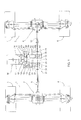
- FIG. 1 shows schematically in a view from above the kinematic arrangement of one embodiment of automotive vehicle according to the invention.
- FIG. 2 shows schematically a side view of a gearbox according to the invention.
- FIG. 3 shows schematically a kinematic chain of a first embodiment of gearbox according to the invention.
- FIG. 4 shows schematically a kinematic chain of a second embodiment of gearbox according to the invention.
- FIG. 5 represents schematically a kinematic chain of a third embodiment of gearbox according to the invention.
- FIG. 6 shows schematically a perspective view of an assembly comprising a gearbox according to the invention shown with the casing partially broken away.
- an embodiment of a vehicle according to the invention comprises a kinematic arrangement with a front axle 1 and a rear axle 2 .
- Front axle 1 is a self-blocking differential axle with limited sliding, driving two front driven and steering wheels 3 and 4 .
- the control of the front axle is a hydrostatic control with a central double-acting jack 5 .
- the rear axle 2 is a self-blocking differential axle with limited sliding to drive and orient two driven and steerable rear wheels 6 and 7 .
- the control of the rear axle is also a hydrostatic control with a central double-acting jack 8 .
- the drive of the front axle 1 is ensured by means of a cardan shaft 9
- the drive of the rear axle 2 is ensured by means of a cardan shaft 10
- the cardan shafts 9 and 10 are connected to two corresponding power outputs of a gearbox 12 designed such that the cardan shafts 9 and 10 will be driven simultaneously at the same speed when the vehicle moves and such that the cardan shafts 9 and 10 will be simultaneously stopped when the vehicle is stopped.
- the gearbox 12 comprises a casing 13 surrounding a torque converter 14 or equivalent clutch with a hollow shaft, adapted to drive an angled transmission 15 with a double conical pinion.
- the converter 14 with a hollow shaft and the angled transmission 15 are traversed by a central shaft 16 for power takeoff, secured to the output shaft 17 of the motor M, or to the inertial flywheel of the internal combustion engine M so as continuously to drive the power takeoff shaft 16 upon starting up the motor M.
- the power takeoff shaft 16 is preferably adapted to drive a pump generating hydraulic or hydrostatic energy, not shown and external to the casing 13 of the gearbox 12 .
- the converter 14 with a hollow shaft or equivalent clutch is connected to the output drive of the internal combustion motor M and constitutes the first member driving the gearbox 12 , whilst the angled transmission 15 is the second driving member secured to the turbine of the converter 14 with a hollow shaft and integrated into the casing 13 of the gearbox 12 .
- the angled transmission 15 with double conical pinion comprises a forward drive pinion 15 a with an associated clutch 18 a and a reverse drive pinion 15 b with an associated clutch 18 b.
- the casing 13 of the gearbox 12 contains three parallel shaft lines A 1 , A 2 , A 3 .
- the first shaft line A 1 corresponding to the angled transmission 15 comprises for forward drive: the pinion 15 a , the associated clutch 18 a and the toothed forward drive wheel 19 a ; and for reverse drive: the pinion 15 b , the associated clutch 18 b and the reverse drive toothed wheel 19 b.
- the toothed wheels for forward drive 19 a or reverse drive 19 b continuously engage with the toothed wheels 20 a , 20 b of the second intermediate shaft A 2 of the transmission, which also comprises toothed wheels 21 , 22 , 23 fixed in rotation with the toothed wheels 20 a , 20 b.
- Each toothed wheel 20 a or 21 or 22 or 23 continuously engages with the toothed wheel 30 or 31 or 32 or 33 of the third shaft line A 3 for driving the cardan shafts 9 and 10 of front and rear axles 1 and 2 .
- the toothed wheels 30 to 33 are mounted freely in rotation on the third shaft line with the possibility of engagement or equivalent synchronous drive with the crowns 34 , 35 mounted securely in rotation with the third shaft line, preferably mounted on grooves on the third shaft 37 with the possibility of lateral movement under the action of mechanical controls of a type known per se and not illustrated.
- the toothed engagement of a crown 34 or 35 with one of the toothed wheels 30 to 33 thus permits selecting the forward speed or rearward speed.
- FIGS. 2 to 4 identical or functionally equivalent elements to FIG. 1 are indicated by the same reference numerals.
- the casing 13 comprises flange 13 a for mounting on the casing C of the flywheel V of the motor M (not shown).
- the converter 14 with a hollow shaft comprises a turbine 14 a with a hollow shaft for driving the angled transmission 15 , a reactor 14 b , and an impeller 14 c secured to the flywheel V of the motor M (not shown).
- the power takeoff shaft 16 is driven by the output shaft 17 of the motor M and passes between the pinions 15 a , 15 b to leave the casing 13 and to drive a hydraulic pump (not shown).
- the three shaft lines described with reference to FIGS. 1 to 6 are schematically shown by the geometrical axes A 1 , A 2 , A 3 .
- the reduced size of the casing 13 and of the gearbox 12 according to the invention corresponds to the mounting of the three shaft lines A 1 , A 2 , A 3 on sealed bearings of known type and does not require a more detailed description.
- the reduction of size in the transverse direction permits obtaining a reduced distance d between the flange 13 a and the axis A 3 of the shaft 37 , preferably comprised between 200 and 500 mm and permits mounting substantially in alignment the cardan shafts 9 and 10 and the third shaft 37 , thereby avoiding the addition of any intermediate transmission and any supplemental gearing.
- the shaft 37 is thus preferably located, after mounting, substantially in the median longitudinal plane of the machine for which the gearbox 12 is provided.
- FIG. 3 shows schematically a first embodiment of gearbox according to the invention adapted for an automotive vehicle of the type described with reference to FIG. 1, comprising reference numerals identical to the reference numerals of FIGS. 1 and 2.
- the casing 13 of gearbox comprises a bell 13 b surrounding the torque converter 14 or equivalent clutch, and a sealed chamber 13 c receiving a hydraulic liquid for lubricating the gearing and the clutches of the gearbox 12 .
- Bell 13 b of casing 13 of gearbox 12 is mounted on the casing C of the motor flywheel V by its flange 13 a.
- the selection of the speed ratio results from the coaction or the reciprocal activity of the different clutch or mechanically toothed members, as indicated in the speed table in which the numeral 1 indicates the clutching activity 18 a or 18 b , or the drive of a crown 34 or 35 and the drive axles 1 and 2 by one of the toothed wheels 30 to 33 of the shaft 34 , whilst the numeral 0 indicates the dead point of the clutch 18 a or 18 b or the absence of activity of a toothed wheel 30 to 33 in the free wheel condition on shaft 37 .
- FIG. 4 shows schematically a second embodiment of gearbox according to the invention, comprising reference numerals identical to those of FIG. 2 .
- This second embodiment differs from the first embodiment by the mechanical arrangement of the third shaft line A 3 , which comprises double clutches, permitting speed change under torque, the “power shift” transmission so called by specialists, with electrical or hydraulic control of known type and not shown in detail.
- the selection of the speed ratio results from the coaction or reciprocal inactivity of the different mechanical clutch members, as indicated in the speed table, in which the numeral 1 indicates the clutching activity 18 a or 18 b or the drive by one of the clutch wheels 40 to 43 with a plate 44 or 45 of the shaft 37 and of the drive axles 1 and 2 , whilst the numeral 0 indicates the dead point of the clutch 18 a or 18 b , or the absence of clutching of a toothed wheel 40 to 43 in the free wheel condition on shaft 37 .
- a third embodiment of gearbox permits changing speeds under torque, the “power shift” transmission so called by specialists, by modifying the mechanical arrangements of the three shaft lines A 1 , A 2 , A 3 .
- These arrangements comprise for example intermediate support bearings 108 and 109 for the first shaft line A 1 comprising the double conical pinion 15 a or 15 b , a double hydraulic forward drive clutch with three plates 100 - 101 - 102 , and associated toothed wheels 103 and 104 secured respectively to the plates 101 and 102 , and a hydraulic clutch with two plates 105 - 106 for reverse drive with an associated toothed wheel 107 secured to the plate 106 .
- the toothed wheels 103 , 104 and 107 of the first shaft line A 1 engage continuously with the corresponding toothed wheels 24 , 26 and 29 of the second shaft line A 2 .
- a wheel 25 or 28 or 29 of the second shaft line A 2 can transmit the movement of the second shaft line A 2 to the third shaft 37 , as a function of the force of the various clutches of the gearbox, and in particular the clutch 27 - 28 of the second shaft line A 2 .
- the toothed wheels 25 , 28 and 29 engage with toothed wheels 50 , 52 and 54 of the third shaft 37 : the first and third toothed wheels 50 and 54 are mounted disengageably and engageably under the action of clutch means 50 - 51 and 53 - 54 respectively.
- the second toothed wheel 52 is mounted fixedly on the shaft 37 , because the toothed wheel 28 of the second shaft line A 2 is disengageable.
- an arrangement with three parallel shaft lines A 1 , A 2 , A 3 of a gearbox according to the invention provides the advantage of having shaft outputs to drive the front and rear axles substantially in the desired plane (in general the longitudinal median plane of the corresponding machine), and moreover permits substantially reducing the longitudinal size of the mechanical assembly comprising the motor M and the gearbox 12 .
- the passage provided through the hollow shaft of the converter 14 to transmit the movement of drive shaft 17 permits reducing the transverse size of the mounting of the hydraulic pumps P driven by the power takeoff shaft 16 , such that the assembly shown comprising the motor M, the gearbox 12 and these hydraulic pumps P has a limited transverse size.
- angled transmission 15 with a double conical pinion 15 a , 15 b supplying alternatively forward movement and reverse movement, permits having a relay shaft to reverse the direction of rotation for reverse drive.
- the invention also covers any modified embodiment not shown, of a gearbox comprising at least three parallel shaft lines and arranged substantially longitudinally, having a reduced size, and of simple and economic construction.
- a gearbox comprising at least three parallel shaft lines and arranged substantially longitudinally, having a reduced size, and of simple and economic construction.
- This modification to reduce the size requires providing a fourth shaft, namely a reversing shaft for reverse movement, parallel to the three shaft lines A 1 , A 2 , A 3 described with reference to FIGS. 1 to 6 .
- This reversing shaft for reverse drive coacts disengageably with the shafts A 1 and A 2 ; when this reversing shaft is disengaged, the gear box according to the invention operates in forward drive; when this reversing shaft is engaged, the movement of shaft A 1 drives the reversing shaft which in turn drives the shaft A 2 and the gearbox operates in reverse drive.
Abstract
A gearbox, particularly for an automotive vehicle with a telescopic load-carrying arm, is adapted to transmit directly or indirectly the drive movement of an internal combustion motor (M) with at least one front or rear axle provided with driven wheels. This gearbox includes a casing (13) containing an angled transmission (15) arranged to transmit the movement of the output shaft (17) of the motor, to a drive shaft (9 or 10) of the front or rear axle, or both. The gearbox further comprises a power takeoff through shaft (16) arranged to drive a pump that generates hydraulic or hydrostatic energy.
Description
This application is based on the disclosure of French application 00.12861 filed in France on Oct. 9, 2000, the entirety of which application is hereby expressly incorporated by reference.
The invention relates to gearboxes, particularly for automotive vehicles with telescopic load-bearing arms.
The invention also relates to an automotive vehicle with a telescopic load-bearing arm provided with a gearbox according to the invention.
Automotive vehicles with telescopic load-bearing arms are known, produced and sold by the MANITOU BF Company in France, in which a diesel motor is oriented transversely to the longitudinal axis of the machine.
The diesel motor drives an angled transmission, of which an output drives a gearbox oriented longitudinally and disposed substantially in a central position and of which another output continuously drives a hydraulic pump upon startup of the motor.
These machines are generally satisfactory, but have a large number of mechanical members (resilient coupling, cardan transmission, angled transmission, torque converter, gearbox), of which certain ones are mounted in individual casings before being assembled together.
This technique results in a substantial size of the assembly produced and a costly fabrication of the mechanical transmission means of these machines.
The invention has for its object to overcome the drawbacks of the prior art, by providing a new gearbox, adapted particularly for new automotive vehicles with a telescopic load-carrying arm, of simple and economical construction and of reduced size.
The invention has for its object a gearbox, particularly for an automotive vehicle with a telescopic load-carrying arm, adapted to transmit directly or indirectly the drive movement of a transversely oriented internal combustion engine, to at least one front or rear axle having drive wheels, by means of at least one longitudinally oriented shaft, characterized in that the casing of the gearbox contains an angled transmission, whose transversely oriented input is adapted to be driven by a clutch means, and whose longitudinally oriented output defines a first shaft line of the gearbox.
According to other advantageous characteristics of the invention:
the gearbox comprises moreover a through power takeoff shaft arranged to drive a pump generating hydraulic or hydrostatic energy
the angled transmission comprises a double conical pinion: a forward drive pinion and a rear drive pinion, with at least one associated clutch,
the gearbox is driven by a torque converter connected to the output of the internal combustion motor by constituting the first drive member from the gearbox, whilst the angled transmission is the second driving member secured to the turbine of the converter.
the casing of the gearbox contains at least three parallel shaft lines: a first shaft line corresponding to the angled transmission, a second intermediate shaft for transmission between the first shaft line and a third shaft line, this third shaft line corresponding to the shaft (or shafts) for driving the front or rear axle (or front or rear drive axles),
the first shaft line corresponding to the angled transmission comprises a double conical pinion engaging with a conical pinion adapted to be driven by the output shaft of the motor, and a double clutch for selectively driving a toothed forward drive wheel or a toothed rearward drive wheel, and these two toothed front and rear drive wheels engaging continuously with toothed wheels of the second intermediate transmission shaft,
the second shaft line comprises several toothed wheels for transmission of movement imparted by the first shaft line to the corresponding toothed wheels of the third shaft line with which they are continuously in engagement,
the corresponding toothed wheels of the third shaft line are mounted freely in rotation on the third shaft, and are adapted to drive this third shaft under the action of clutch or toothed means,
the third shaft line moreover comprises a toothed wheel mounted securely on the third shaft and engaging with a toothed wheel disengageable from the second shaft line, so as to provide a number of forward drive speeds that is greater than the number of rearward drive speeds,
the third shaft line comprises two shaft output adapted to drive simultaneously a front drive axle and a rear drive axle of an automotive vehicle, particularly a vehicle with a telescopic load-carrying arm.
The invention also has for its object an automotive vehicle with a telescopic load-carrying arm, of the type comprising two front and rear axles provided with wheels, and an internal combustion engine driving a gearbox.
The invention will be better understood from the description which follows, given by way of non-limiting example, with reference to the accompanying drawings, in which:
FIG. 1 shows schematically in a view from above the kinematic arrangement of one embodiment of automotive vehicle according to the invention.
FIG. 2 shows schematically a side view of a gearbox according to the invention.
FIG. 3 shows schematically a kinematic chain of a first embodiment of gearbox according to the invention.
FIG. 4 shows schematically a kinematic chain of a second embodiment of gearbox according to the invention.
FIG. 5 represents schematically a kinematic chain of a third embodiment of gearbox according to the invention.
FIG. 6 shows schematically a perspective view of an assembly comprising a gearbox according to the invention shown with the casing partially broken away.
Referring to FIG. 1, an embodiment of a vehicle according to the invention comprises a kinematic arrangement with a front axle 1 and a rear axle 2. Front axle 1 is a self-blocking differential axle with limited sliding, driving two front driven and steering wheels 3 and 4. The control of the front axle is a hydrostatic control with a central double-acting jack 5.
The rear axle 2 is a self-blocking differential axle with limited sliding to drive and orient two driven and steerable rear wheels 6 and 7.
The control of the rear axle is also a hydrostatic control with a central double-acting jack 8.
The drive of the front axle 1 is ensured by means of a cardan shaft 9, whilst the drive of the rear axle 2 is ensured by means of a cardan shaft 10. The cardan shafts 9 and 10 are connected to two corresponding power outputs of a gearbox 12 designed such that the cardan shafts 9 and 10 will be driven simultaneously at the same speed when the vehicle moves and such that the cardan shafts 9 and 10 will be simultaneously stopped when the vehicle is stopped.
The gearbox 12 comprises a casing 13 surrounding a torque converter 14 or equivalent clutch with a hollow shaft, adapted to drive an angled transmission 15 with a double conical pinion.
The converter 14 with a hollow shaft and the angled transmission 15 are traversed by a central shaft 16 for power takeoff, secured to the output shaft 17 of the motor M, or to the inertial flywheel of the internal combustion engine M so as continuously to drive the power takeoff shaft 16 upon starting up the motor M. The power takeoff shaft 16 is preferably adapted to drive a pump generating hydraulic or hydrostatic energy, not shown and external to the casing 13 of the gearbox 12.
Preferably, the converter 14 with a hollow shaft or equivalent clutch is connected to the output drive of the internal combustion motor M and constitutes the first member driving the gearbox 12, whilst the angled transmission 15 is the second driving member secured to the turbine of the converter 14 with a hollow shaft and integrated into the casing 13 of the gearbox 12.
The angled transmission 15 with double conical pinion comprises a forward drive pinion 15 a with an associated clutch 18 a and a reverse drive pinion 15 b with an associated clutch 18 b.
The casing 13 of the gearbox 12 contains three parallel shaft lines A1, A2, A3.
The first shaft line A1 corresponding to the angled transmission 15 comprises for forward drive: the pinion 15 a, the associated clutch 18 a and the toothed forward drive wheel 19 a; and for reverse drive: the pinion 15 b, the associated clutch 18 b and the reverse drive toothed wheel 19 b.
The toothed wheels for forward drive 19 a or reverse drive 19 b continuously engage with the toothed wheels 20 a, 20 b of the second intermediate shaft A2 of the transmission, which also comprises toothed wheels 21, 22, 23 fixed in rotation with the toothed wheels 20 a, 20 b.
Each toothed wheel 20 a or 21 or 22 or 23 continuously engages with the toothed wheel 30 or 31 or 32 or 33 of the third shaft line A3 for driving the cardan shafts 9 and 10 of front and rear axles 1 and 2.
The toothed wheels 30 to 33 are mounted freely in rotation on the third shaft line with the possibility of engagement or equivalent synchronous drive with the crowns 34, 35 mounted securely in rotation with the third shaft line, preferably mounted on grooves on the third shaft 37 with the possibility of lateral movement under the action of mechanical controls of a type known per se and not illustrated.
The toothed engagement of a crown 34 or 35 with one of the toothed wheels 30 to 33 thus permits selecting the forward speed or rearward speed.
With reference to FIGS. 2 to 4, identical or functionally equivalent elements to FIG. 1 are indicated by the same reference numerals.
In FIG. 2, the casing 13 comprises flange 13 a for mounting on the casing C of the flywheel V of the motor M (not shown). The converter 14 with a hollow shaft comprises a turbine 14 a with a hollow shaft for driving the angled transmission 15, a reactor 14 b, and an impeller 14 c secured to the flywheel V of the motor M (not shown). The power takeoff shaft 16 is driven by the output shaft 17 of the motor M and passes between the pinions 15 a, 15 b to leave the casing 13 and to drive a hydraulic pump (not shown).
The three shaft lines described with reference to FIGS. 1 to 6 are schematically shown by the geometrical axes A1, A2, A3.
The reduced size of the casing 13 and of the gearbox 12 according to the invention corresponds to the mounting of the three shaft lines A1, A2, A3 on sealed bearings of known type and does not require a more detailed description.
The reduction of size in the transverse direction permits obtaining a reduced distance d between the flange 13 a and the axis A3 of the shaft 37, preferably comprised between 200 and 500 mm and permits mounting substantially in alignment the cardan shafts 9 and 10 and the third shaft 37, thereby avoiding the addition of any intermediate transmission and any supplemental gearing.
The shaft 37 is thus preferably located, after mounting, substantially in the median longitudinal plane of the machine for which the gearbox 12 is provided.
FIG. 3 shows schematically a first embodiment of gearbox according to the invention adapted for an automotive vehicle of the type described with reference to FIG. 1, comprising reference numerals identical to the reference numerals of FIGS. 1 and 2.
In this embodiment, the casing 13 of gearbox comprises a bell 13 b surrounding the torque converter 14 or equivalent clutch, and a sealed chamber 13 c receiving a hydraulic liquid for lubricating the gearing and the clutches of the gearbox 12.
Bell 13 b of casing 13 of gearbox 12 is mounted on the casing C of the motor flywheel V by its flange 13 a.
The selection of the speed ratio results from the coaction or the reciprocal activity of the different clutch or mechanically toothed members, as indicated in the speed table in which the numeral 1 indicates the clutching activity 18 a or 18 b, or the drive of a crown 34 or 35 and the drive axles 1 and 2 by one of the toothed wheels 30 to 33 of the shaft 34, whilst the numeral 0 indicates the dead point of the clutch 18 a or 18 b or the absence of activity of a toothed wheel 30 to 33 in the free wheel condition on shaft 37.
FIG. 4 shows schematically a second embodiment of gearbox according to the invention, comprising reference numerals identical to those of FIG. 2.
This second embodiment differs from the first embodiment by the mechanical arrangement of the third shaft line A3, which comprises double clutches, permitting speed change under torque, the “power shift” transmission so called by specialists, with electrical or hydraulic control of known type and not shown in detail.
In the first and second embodiments described with reference to FIGS. 3 and 4, it is possible to select four forward speeds and four reverse speeds, to turn the shaft 37 in the corresponding regime and in the corresponding direction and to transmit its movement by cardan shafts 9 and 10 in the middle of the drive axles 1 and 2.
The selection of the speed ratio results from the coaction or reciprocal inactivity of the different mechanical clutch members, as indicated in the speed table, in which the numeral 1 indicates the clutching activity 18 a or 18 b or the drive by one of the clutch wheels 40 to 43 with a plate 44 or 45 of the shaft 37 and of the drive axles 1 and 2, whilst the numeral 0 indicates the dead point of the clutch 18 a or 18 b, or the absence of clutching of a toothed wheel 40 to 43 in the free wheel condition on shaft 37.
With reference to FIG. 5, identical or functionally equivalent elements to those of FIG. 4 are shown by the same reference numerals.
In FIG. 5, a third embodiment of gearbox according to the invention permits changing speeds under torque, the “power shift” transmission so called by specialists, by modifying the mechanical arrangements of the three shaft lines A1, A2, A3. These arrangements comprise for example intermediate support bearings 108 and 109 for the first shaft line A1 comprising the double conical pinion 15 a or 15 b, a double hydraulic forward drive clutch with three plates 100-101-102, and associated toothed wheels 103 and 104 secured respectively to the plates 101 and 102, and a hydraulic clutch with two plates 105-106 for reverse drive with an associated toothed wheel 107 secured to the plate 106. The toothed wheels 103, 104 and 107 of the first shaft line A1 engage continuously with the corresponding toothed wheels 24, 26 and 29 of the second shaft line A2.
A wheel 25 or 28 or 29 of the second shaft line A2 can transmit the movement of the second shaft line A2 to the third shaft 37, as a function of the force of the various clutches of the gearbox, and in particular the clutch 27-28 of the second shaft line A2.
The toothed wheels 25, 28 and 29 engage with toothed wheels 50, 52 and 54 of the third shaft 37: the first and third toothed wheels 50 and 54 are mounted disengageably and engageably under the action of clutch means 50-51 and 53-54 respectively. The second toothed wheel 52 is mounted fixedly on the shaft 37, because the toothed wheel 28 of the second shaft line A2 is disengageable.
These arrangements permit obtaining six forward speeds and three reverse speeds, as will be seen from the speed table indicating the condition of driving (1) or not (0) of one of the toothed wheels 103, 104 or 107 or of a member 51, 52 or 53 of the third shaft 37 as a function of the force of the various forward drive clutches 100-101, 100-102, or of reverse drive 105-106 and selection clutches 50-51, 27-28, 53-54 of the two shaft lines A2 and A3.
With reference to FIG. 6, an arrangement with three parallel shaft lines A1, A2, A3 of a gearbox according to the invention provides the advantage of having shaft outputs to drive the front and rear axles substantially in the desired plane (in general the longitudinal median plane of the corresponding machine), and moreover permits substantially reducing the longitudinal size of the mechanical assembly comprising the motor M and the gearbox 12.
Similarly, the passage provided through the hollow shaft of the converter 14 to transmit the movement of drive shaft 17 permits reducing the transverse size of the mounting of the hydraulic pumps P driven by the power takeoff shaft 16, such that the assembly shown comprising the motor M, the gearbox 12 and these hydraulic pumps P has a limited transverse size.
Moreover, the use of angled transmission 15 with a double conical pinion 15 a, 15 b supplying alternatively forward movement and reverse movement, permits having a relay shaft to reverse the direction of rotation for reverse drive.
The invention described with reference to particular embodiments is in no way thereby limited, but on the contrary covers any modification of form and all variation of embodiment within the scope and spirit of the invention.
Thus, the invention also covers any modified embodiment not shown, of a gearbox comprising at least three parallel shaft lines and arranged substantially longitudinally, having a reduced size, and of simple and economic construction. To this end, there can be used an angled transmission with a single conical pinion instead of an angled transmission with a double conical pinion described with reference to FIGS. 1 to 6, so as to reduce the longitudinal size of the gearbox by a length corresponding to the reverse drive pinion 15 b, to the associated clutch 18 b and to the toothed reverse drive wheel 19 b. This modification to reduce the size requires providing a fourth shaft, namely a reversing shaft for reverse movement, parallel to the three shaft lines A1, A2, A3 described with reference to FIGS. 1 to 6.
This reversing shaft for reverse drive coacts disengageably with the shafts A1 and A2; when this reversing shaft is disengaged, the gear box according to the invention operates in forward drive; when this reversing shaft is engaged, the movement of shaft A1 drives the reversing shaft which in turn drives the shaft A2 and the gearbox operates in reverse drive.
The increase of the dimension of the gearbox in the transverse direction by virtue of the addition of this reversing shaft is compensated by the decrease of the longitudinal size of the gearbox, such that the volume of the casing of this modification is comparable to the volume of the casing 13 described with reference to FIGS. 5 and 6.
Claims (8)
1. A gearbox adapted to transmit drive movement from an internal combustion motor oriented transversely, to at least one front or rear axle provided with driven wheels via at least one longitudinally oriented shaft, the gearbox comprising:
a casing that contains an angled transmission having a transversely oriented input and a longitudinally oriented output defining a first shaft line of the gearbox;
at least three parallel shaft lines comprising the first shaft line corresponding to the angled transmission, a second shaft line for transmission between the first and a third shaft line, said third shaft line corresponding to a drive shaft of a said front or rear axle;
the first shaft line corresponding to the angled transmission comprising a double conical pinion engaging with a conical portion adapted to be driven by an output shaft of the motor and a double clutch for selectively driving a toothed forward drive wheel or a toothed reverse drive wheel, said two toothed wheels engaging continuously with toothed wheels on said second intermediate transmission shaft; and
a torque converter structured and arranged to drive the transversely oriented input.
2. The gearbox according to claim 1 , further comprising a power takeoff through shaft that drives a pump which generates hydraulic or hydrostatic energy.
3. The gearbox according to claim 1 , wherein said double conical pinion comprises a forward drive pinion and a rearward drive pinion, with at least one associated clutch.
4. The gearbox according to claim 1 , wherein the second shaft line comprises several toothed wheels for transmission of movement imparted by the first shaft line to corresponding toothed wheels of the third shaft line with which said toothed wheels are continuously in engagement.
5. The gearbox according to claim 4 , wherein said corresponding toothed wheels of the third shaft line are mounted freely in rotation on said third shaft, and are adapted to drive said third shaft under the action of clutch or toothed means.
6. The gearbox according to claim 5 , wherein the third shaft line further comprises a toothed wheel mounted securely to the third shaft and engaging with a disengageable toothed wheel of the second shaft line, so as to provide a number of forward speeds greater than the number of reverse speeds.
7. The gearbox according to claim 6 , wherein the third shaft line comprises two output shafts adapted simultaneously to drive said front and rear axles.
8. An automotive vehicle comprising a telescopic load-carrying arm, and a gearbox as claimed in claim 1 .
Applications Claiming Priority (2)
| Application Number | Priority Date | Filing Date | Title |
|---|---|---|---|
| FR00.12861 | 2000-10-09 | ||
| FR0012861A FR2815102B1 (en) | 2000-10-09 | 2000-10-09 | GEARBOX, PARTICULARLY FOR SELF-PROPELLED VEHICLES WITH TELESCOPIC LOADER ARM |
Publications (2)
| Publication Number | Publication Date |
|---|---|
| US20020040621A1 US20020040621A1 (en) | 2002-04-11 |
| US6655488B2 true US6655488B2 (en) | 2003-12-02 |
Family
ID=8855120
Family Applications (1)
| Application Number | Title | Priority Date | Filing Date |
|---|---|---|---|
| US09/971,636 Expired - Lifetime US6655488B2 (en) | 2000-10-09 | 2001-10-09 | Gearbox, particularly for automotive vehicle with telescopic load-carrying arm |
Country Status (5)
| Country | Link |
|---|---|
| US (1) | US6655488B2 (en) |
| EP (1) | EP1195282B1 (en) |
| AT (1) | ATE313453T1 (en) |
| DE (1) | DE60116023T2 (en) |
| FR (1) | FR2815102B1 (en) |
Cited By (14)
| Publication number | Priority date | Publication date | Assignee | Title |
|---|---|---|---|---|
| US20030230444A1 (en) * | 2002-06-13 | 2003-12-18 | Mathukia Shri Bhanjibhai | Tractor having a convertible front end and variable track width and related methods |
| US20040251069A1 (en) * | 2003-06-07 | 2004-12-16 | Scott Austin | 4 x 4 Conversion kit |
| US20050115750A1 (en) * | 2003-12-02 | 2005-06-02 | Aisin Aw Co., Ltd. | Hybrid drive unit and vehicle mounted therewith |
| US20070227282A1 (en) * | 2006-03-31 | 2007-10-04 | Magna Powertrain Usa, Inc. | Dual Clutch Powershift Transmission |
| WO2008067207A1 (en) | 2006-11-29 | 2008-06-05 | Cadbury Adams Usa Llc | Confectionery compositions including an elastomeric component and a saccharide component |
| US20080271940A1 (en) * | 2007-05-04 | 2008-11-06 | De Craemer Thomas M M | Transmission system for a vehicle |
| US20090235780A1 (en) * | 2008-03-20 | 2009-09-24 | American Axle & Manufacturing, Inc. | Power Transfer Unit with Dual Hypoid Geartrain |
| US20090240388A1 (en) * | 2008-03-19 | 2009-09-24 | Zero Emission Systems, Inc. | Data acquisition for operation of a vehicle |
| US7921950B2 (en) * | 2006-11-10 | 2011-04-12 | Clean Emissions Technologies, Inc. | Electric traction retrofit |
| US20110202234A1 (en) * | 2007-04-03 | 2011-08-18 | Zero Emission Systems, Inc. | Over the road/traction/cabin comfort retrofit |
| US8286440B2 (en) | 2005-03-14 | 2012-10-16 | Clean Emissions Technologies, Inc. | Operating a comfort subsystem for a vehicle |
| US9631528B2 (en) | 2009-09-03 | 2017-04-25 | Clean Emissions Technologies, Inc. | Vehicle reduced emission deployment |
| US9758146B2 (en) | 2008-04-01 | 2017-09-12 | Clean Emissions Technologies, Inc. | Dual mode clutch pedal for vehicle |
| US11287016B2 (en) | 2016-03-03 | 2022-03-29 | Dana Belgium N.V. | Multi-gear transmission layout |
Families Citing this family (8)
| Publication number | Priority date | Publication date | Assignee | Title |
|---|---|---|---|---|
| JP2002362174A (en) * | 2001-04-03 | 2002-12-18 | Komatsu Ltd | Wheel type running work vehicle |
| JP4805350B2 (en) * | 2005-06-15 | 2011-11-02 | ボルボ ラストバグナー アーベー | Vehicle drive system |
| DE102005029112A1 (en) * | 2005-06-23 | 2007-01-11 | Volkswagen Ag | Powertrain of a motor vehicle |
| CN103387183B (en) * | 2013-08-20 | 2015-09-16 | 徐州重型机械有限公司 | A kind of oil pump device without drift angle driving and hoisting crane |
| CN103738171B (en) * | 2013-12-21 | 2016-01-20 | 柳州正菱集团有限公司 | Automotive trannsmission system |
| CN103738175B (en) * | 2013-12-21 | 2016-01-20 | 柳州正菱集团有限公司 | Automotive trannsmission system |
| CN103738172B (en) * | 2013-12-21 | 2016-01-20 | 柳州正菱集团有限公司 | Automotive trannsmission system |
| CN103738170B (en) * | 2013-12-21 | 2016-03-30 | 柳州正菱集团有限公司 | Automotive trannsmission system |
Citations (12)
| Publication number | Priority date | Publication date | Assignee | Title |
|---|---|---|---|---|
| US751540A (en) * | 1904-02-09 | David L Mcclintock | Power-transmitting mechanism. | |
| US1678411A (en) * | 1926-12-31 | 1928-07-24 | Ennes L Westmoreland | Extensible chassis for automobiles |
| US2262710A (en) * | 1937-11-16 | 1941-11-11 | Maybach Motorenbau Gmbh | Transmission for rail cars driven by internal combustion engines |
| FR2339509A2 (en) | 1975-01-22 | 1977-08-26 | Durand Francois | Motor vehicle transmission system - has engine mounted at side of vehicle, with rear wheel at opposite side driven through converting gears and propellor shafts |
| US4618022A (en) * | 1985-01-16 | 1986-10-21 | Toyota Jidosha Kabushiki Kaisha | Power transfer device for four-wheel drive vehicle |
| US4819755A (en) * | 1988-03-14 | 1989-04-11 | Deere & Company | Telescoping drive shaft having lubricating passage |
| US4895217A (en) * | 1986-12-20 | 1990-01-23 | Deere & Company | Drive system for two pairs of wheels |
| DE3925409A1 (en) * | 1989-08-01 | 1991-02-07 | Getrag Getriebe Zahnrad | Vehicle engine, gearbox and driven axle - are assembled with gearbox mounted at angle, pref. between 60 and 90 deg., to the transverse engine |
| JPH0478620A (en) * | 1990-03-20 | 1992-03-12 | Mitsubishi Motors Corp | Structure of driving force distribution system for four wheel drive |
| FR2700303A1 (en) | 1993-01-08 | 1994-07-13 | Renault | Transmission device for four wheel drive vehicle having central differential locking mechanism |
| EP0656315A1 (en) | 1993-12-01 | 1995-06-07 | Manitou Bf | Forklift truck with telescopic arm |
| EP0937827A1 (en) | 1998-02-20 | 1999-08-25 | Manitou Bf | Motor vehicle with telescopic loader arm |
Family Cites Families (5)
| Publication number | Priority date | Publication date | Assignee | Title |
|---|---|---|---|---|
| US1991575A (en) * | 1934-01-20 | 1935-02-19 | Gen Motors Corp | Cross engine drive |
| FR2164001A5 (en) * | 1971-12-09 | 1973-07-27 | Peugeot & Renault | |
| GB2154963A (en) * | 1984-02-27 | 1985-09-18 | Nat Res Dev | Drive systems for automobile vehicles |
| JPH079870A (en) * | 1993-06-23 | 1995-01-13 | Yamaha Motor Co Ltd | Power unit for vehicle |
| ATE240852T1 (en) * | 1997-10-16 | 2003-06-15 | Msd Special Vehicle Engineerin | POWERTRAIN ARRANGEMENT |
-
2000
- 2000-10-09 FR FR0012861A patent/FR2815102B1/en not_active Expired - Lifetime
-
2001
- 2001-10-01 EP EP01402521A patent/EP1195282B1/en not_active Expired - Lifetime
- 2001-10-01 AT AT01402521T patent/ATE313453T1/en active
- 2001-10-01 DE DE60116023T patent/DE60116023T2/en not_active Expired - Lifetime
- 2001-10-09 US US09/971,636 patent/US6655488B2/en not_active Expired - Lifetime
Patent Citations (12)
| Publication number | Priority date | Publication date | Assignee | Title |
|---|---|---|---|---|
| US751540A (en) * | 1904-02-09 | David L Mcclintock | Power-transmitting mechanism. | |
| US1678411A (en) * | 1926-12-31 | 1928-07-24 | Ennes L Westmoreland | Extensible chassis for automobiles |
| US2262710A (en) * | 1937-11-16 | 1941-11-11 | Maybach Motorenbau Gmbh | Transmission for rail cars driven by internal combustion engines |
| FR2339509A2 (en) | 1975-01-22 | 1977-08-26 | Durand Francois | Motor vehicle transmission system - has engine mounted at side of vehicle, with rear wheel at opposite side driven through converting gears and propellor shafts |
| US4618022A (en) * | 1985-01-16 | 1986-10-21 | Toyota Jidosha Kabushiki Kaisha | Power transfer device for four-wheel drive vehicle |
| US4895217A (en) * | 1986-12-20 | 1990-01-23 | Deere & Company | Drive system for two pairs of wheels |
| US4819755A (en) * | 1988-03-14 | 1989-04-11 | Deere & Company | Telescoping drive shaft having lubricating passage |
| DE3925409A1 (en) * | 1989-08-01 | 1991-02-07 | Getrag Getriebe Zahnrad | Vehicle engine, gearbox and driven axle - are assembled with gearbox mounted at angle, pref. between 60 and 90 deg., to the transverse engine |
| JPH0478620A (en) * | 1990-03-20 | 1992-03-12 | Mitsubishi Motors Corp | Structure of driving force distribution system for four wheel drive |
| FR2700303A1 (en) | 1993-01-08 | 1994-07-13 | Renault | Transmission device for four wheel drive vehicle having central differential locking mechanism |
| EP0656315A1 (en) | 1993-12-01 | 1995-06-07 | Manitou Bf | Forklift truck with telescopic arm |
| EP0937827A1 (en) | 1998-02-20 | 1999-08-25 | Manitou Bf | Motor vehicle with telescopic loader arm |
Cited By (23)
| Publication number | Priority date | Publication date | Assignee | Title |
|---|---|---|---|---|
| US20030230444A1 (en) * | 2002-06-13 | 2003-12-18 | Mathukia Shri Bhanjibhai | Tractor having a convertible front end and variable track width and related methods |
| US6902022B2 (en) * | 2002-06-13 | 2005-06-07 | Society For Research And Initiatives (Sristi) | Tractor having a convertible front end and variable track width and related methods |
| US20040251069A1 (en) * | 2003-06-07 | 2004-12-16 | Scott Austin | 4 x 4 Conversion kit |
| US20050115750A1 (en) * | 2003-12-02 | 2005-06-02 | Aisin Aw Co., Ltd. | Hybrid drive unit and vehicle mounted therewith |
| US7350603B2 (en) * | 2003-12-02 | 2008-04-01 | Aisin Aw Co., Ltd. | Hybrid drive unit and vehicle mounted therewith |
| US8286440B2 (en) | 2005-03-14 | 2012-10-16 | Clean Emissions Technologies, Inc. | Operating a comfort subsystem for a vehicle |
| US9457792B2 (en) | 2006-03-14 | 2016-10-04 | Clean Emissions Technologies, Inc. | Retrofitting a vehicle drive train |
| US8668035B2 (en) | 2006-03-14 | 2014-03-11 | Clean Emissions Technologies, Inc. | Electric traction system and method |
| US7665376B2 (en) * | 2006-03-31 | 2010-02-23 | Magna Powertrain Usa, Inc. | Dual clutch powershift transmission |
| US20070227282A1 (en) * | 2006-03-31 | 2007-10-04 | Magna Powertrain Usa, Inc. | Dual Clutch Powershift Transmission |
| US7921950B2 (en) * | 2006-11-10 | 2011-04-12 | Clean Emissions Technologies, Inc. | Electric traction retrofit |
| EP2548452A1 (en) | 2006-11-29 | 2013-01-23 | Kraft Foods Global Brands LLC | Confectionery compositions uncluding an elstomeric component and a saccharide component |
| WO2008067207A1 (en) | 2006-11-29 | 2008-06-05 | Cadbury Adams Usa Llc | Confectionery compositions including an elastomeric component and a saccharide component |
| US20110202234A1 (en) * | 2007-04-03 | 2011-08-18 | Zero Emission Systems, Inc. | Over the road/traction/cabin comfort retrofit |
| US8565969B2 (en) | 2007-04-03 | 2013-10-22 | Clean Emissions Technologies, Inc. | Over the road/traction/cabin comfort retrofit |
| US20080271940A1 (en) * | 2007-05-04 | 2008-11-06 | De Craemer Thomas M M | Transmission system for a vehicle |
| US20090240388A1 (en) * | 2008-03-19 | 2009-09-24 | Zero Emission Systems, Inc. | Data acquisition for operation of a vehicle |
| US9707861B2 (en) | 2008-03-19 | 2017-07-18 | Clean Emissions Technologies, Inc. | Data acquisition for operation of a vehicle |
| US8381861B2 (en) * | 2008-03-20 | 2013-02-26 | American Axle & Manufacturing, Inc. | Power transfer unit with dual hypoid geartrain |
| US20090235780A1 (en) * | 2008-03-20 | 2009-09-24 | American Axle & Manufacturing, Inc. | Power Transfer Unit with Dual Hypoid Geartrain |
| US9758146B2 (en) | 2008-04-01 | 2017-09-12 | Clean Emissions Technologies, Inc. | Dual mode clutch pedal for vehicle |
| US9631528B2 (en) | 2009-09-03 | 2017-04-25 | Clean Emissions Technologies, Inc. | Vehicle reduced emission deployment |
| US11287016B2 (en) | 2016-03-03 | 2022-03-29 | Dana Belgium N.V. | Multi-gear transmission layout |
Also Published As
| Publication number | Publication date |
|---|---|
| DE60116023T2 (en) | 2006-07-27 |
| US20020040621A1 (en) | 2002-04-11 |
| ATE313453T1 (en) | 2006-01-15 |
| FR2815102B1 (en) | 2004-11-26 |
| DE60116023D1 (en) | 2006-01-26 |
| FR2815102A1 (en) | 2002-04-12 |
| EP1195282A1 (en) | 2002-04-10 |
| EP1195282B1 (en) | 2005-12-21 |
Similar Documents
| Publication | Publication Date | Title |
|---|---|---|
| US6655488B2 (en) | Gearbox, particularly for automotive vehicle with telescopic load-carrying arm | |
| KR101575272B1 (en) | Transmission system of hybrid electric vehicle | |
| KR100354183B1 (en) | Multi-speed reverse transmission | |
| JPS5884248A (en) | Driving equipment for automobile | |
| CN218777413U (en) | Electric drive bridge structure driven by single motor | |
| JP3431928B2 (en) | Power transmission device | |
| KR950002365B1 (en) | Transmission for working vehicle | |
| CN110778664A (en) | Transmission transfer case of amphibious vehicle | |
| CN202674221U (en) | Six-gear planetary type hydrodynamic drive device | |
| GB1097241A (en) | Improvements in or relating to power plants, especially but not exclusively ground vehicle power plants | |
| JP4326977B2 (en) | Transmission | |
| CN112356653A (en) | Hybrid electric drive device | |
| JP2802626B2 (en) | Power transmission case structure | |
| US3332299A (en) | Drive particularly for small tractors with high-speed driving motors | |
| CN218400195U (en) | Two grades of hybrid assembly structures | |
| CN218343265U (en) | Power transmission system and engineering machinery | |
| CN215673428U (en) | Gearbox assembly and tractor | |
| CN220785437U (en) | Double-planet row mixing system | |
| EP4116122A1 (en) | An electric powertrain for a vehicle | |
| CN111765221B (en) | Compound differential planetary mechanism of stepless speed change tractor | |
| CN211820589U (en) | Transmission transfer case of amphibious vehicle | |
| US4805713A (en) | Power transmitting system for a four-wheel drive vehicle | |
| CN214699151U (en) | Reverse gear assembly with hydraulic oil pump output | |
| CN212643451U (en) | Tractor front power output mechanism | |
| CN218953941U (en) | Harvester gearbox of vertical overall arrangement |
Legal Events
| Date | Code | Title | Description |
|---|---|---|---|
| AS | Assignment |
Owner name: MANIFOU BF, FRANCE Free format text: ASSIGNMENT OF ASSIGNORS INTEREST;ASSIGNOR:BRAUD, MARCEL-CLAUDE;REEL/FRAME:012241/0629 Effective date: 20010924 |
|
| STCF | Information on status: patent grant |
Free format text: PATENTED CASE |
|
| FPAY | Fee payment |
Year of fee payment: 4 |
|
| FEPP | Fee payment procedure |
Free format text: PAYOR NUMBER ASSIGNED (ORIGINAL EVENT CODE: ASPN); ENTITY STATUS OF PATENT OWNER: LARGE ENTITY |
|
| FPAY | Fee payment |
Year of fee payment: 8 |
|
| FPAY | Fee payment |
Year of fee payment: 12 |