US6510491B1 - System and method for accomplishing data storage migration between raid levels - Google Patents
System and method for accomplishing data storage migration between raid levels Download PDFInfo
- Publication number
- US6510491B1 US6510491B1 US09/465,057 US46505799A US6510491B1 US 6510491 B1 US6510491 B1 US 6510491B1 US 46505799 A US46505799 A US 46505799A US 6510491 B1 US6510491 B1 US 6510491B1
- Authority
- US
- United States
- Prior art keywords
- container
- data
- container structure
- mapping
- raid
- Prior art date
- Legal status (The legal status is an assumption and is not a legal conclusion. Google has not performed a legal analysis and makes no representation as to the accuracy of the status listed.)
- Expired - Lifetime
Links
- 238000000034 method Methods 0.000 title claims abstract description 26
- 238000013508 migration Methods 0.000 title description 23
- 230000005012 migration Effects 0.000 title description 23
- 238000013500 data storage Methods 0.000 title description 4
- 238000013507 mapping Methods 0.000 claims abstract description 37
- 238000012546 transfer Methods 0.000 claims abstract description 6
- 238000004891 communication Methods 0.000 claims description 5
- 238000005192 partition Methods 0.000 description 18
- 230000008569 process Effects 0.000 description 12
- 238000010586 diagram Methods 0.000 description 10
- 238000012545 processing Methods 0.000 description 6
- 230000008901 benefit Effects 0.000 description 2
- 230000008859 change Effects 0.000 description 2
- 230000008520 organization Effects 0.000 description 2
- 238000007792 addition Methods 0.000 description 1
- 238000013459 approach Methods 0.000 description 1
- 230000008602 contraction Effects 0.000 description 1
- 230000000694 effects Effects 0.000 description 1
- 230000006870 function Effects 0.000 description 1
- 238000007726 management method Methods 0.000 description 1
- 238000012986 modification Methods 0.000 description 1
- 230000004048 modification Effects 0.000 description 1
Images


Classifications
-
- G—PHYSICS
- G06—COMPUTING; CALCULATING OR COUNTING
- G06F—ELECTRIC DIGITAL DATA PROCESSING
- G06F11/00—Error detection; Error correction; Monitoring
- G06F11/07—Responding to the occurrence of a fault, e.g. fault tolerance
- G06F11/08—Error detection or correction by redundancy in data representation, e.g. by using checking codes
- G06F11/10—Adding special bits or symbols to the coded information, e.g. parity check, casting out 9's or 11's
- G06F11/1076—Parity data used in redundant arrays of independent storages, e.g. in RAID systems
- G06F11/1096—Parity calculation or recalculation after configuration or reconfiguration of the system
-
- G—PHYSICS
- G06—COMPUTING; CALCULATING OR COUNTING
- G06F—ELECTRIC DIGITAL DATA PROCESSING
- G06F3/00—Input arrangements for transferring data to be processed into a form capable of being handled by the computer; Output arrangements for transferring data from processing unit to output unit, e.g. interface arrangements
- G06F3/06—Digital input from, or digital output to, record carriers, e.g. RAID, emulated record carriers or networked record carriers
- G06F3/0601—Interfaces specially adapted for storage systems
-
- G—PHYSICS
- G06—COMPUTING; CALCULATING OR COUNTING
- G06F—ELECTRIC DIGITAL DATA PROCESSING
- G06F3/00—Input arrangements for transferring data to be processed into a form capable of being handled by the computer; Output arrangements for transferring data from processing unit to output unit, e.g. interface arrangements
- G06F3/06—Digital input from, or digital output to, record carriers, e.g. RAID, emulated record carriers or networked record carriers
- G06F2003/0697—Digital input from, or digital output to, record carriers, e.g. RAID, emulated record carriers or networked record carriers device management, e.g. handlers, drivers, I/O schedulers
Definitions
- the invention relates generally to the field of computer systems and more particularly to system that employ redundant array of independent disks (RAID) architecture.
- RAID redundant array of independent disks
- a computer system includes an operating system whose primary function is the management of hardware and software resources in the computer system.
- the operating system handles input/output (I/O) requests from software processes or applications to exchange data with on-line external storage devices in a storage subsystem.
- the operating system (such as Windows NT® available from Microsoft, Corp. of Redmond, Wash.) forwards I/O requests to an I/O subsystem, which, in turn, converts the logical addresses is into physical locations in the storage devices and commands the latter devices to engage in the requested storage or retrieval operations.
- the on-line storage devices on a computer are configured from one or more disks into logical units of storage space referred to herein as “containers.”
- containers include volume sets, stripe sets, mirror sets, and various Redundant Array of Independent Disk (RAID) implementations.
- a volume set comprises one or more physical partitions, i.e., collections of blocks of contiguous space on disks, and is composed of space on one or more disks. Data is stored in a volume set by filling all of the volume's partitions in one disk drive before using volume partitions in another disk drive.
- a stripe set is a series of partitions on multiple disks, one partition per disk, that is combined into a single logical volume.
- a stripe set In its basic configuration, a stripe set is also known as a “RAID 0 ” configuration.
- a mirror set is composed of volumes on multiple disks, whereby a volume on one disk is a duplicate copy of an equal sized volume on another disk in order to provide data redundancy.
- a basic configuration for a mirror set is known as “RAID 1 .”
- the configuration is known as “RAID 5 .”
- RAID 10 the resulting configuration.
- all configurations of the RAID implementation (RAID 0 - 10 ) provide a collection of partitions, where each partition is composed of space from one disk in order to support data redundancy.
- the I/O subsystem configures the containers through a software entity called a “container manager.” Essentially the container manager sets up a mapping structure to efficiently map logical addresses received from the operating system to physical addresses on storage devices.
- the I/O subsystem also includes a software driver for each type of container configuration on the system. These drivers use the mapping structure to derive the physical addresses, which they then pass to the prospective storage devices for storage and retrieval operations.
- the I/O subsystem's container manager configures the containers and maintains the configuration tables in a container layer of the I/O subsystem.
- the container layer of the I/O subsystem comprises a Device Switch Table, a Container Array, and a Partition Table.
- the teachings of this application are expressly incorporated herein by reference.
- the Device Switch table consists of entries; each of which ordinarily points to the entry point of a container driver that performs I/O operations on a particular type of container.
- the Container Array is a table of entries, each of which ordinarily points to data structures used by a container driver. There is a fixed one-to-one relationship between the Device Switch Table and the Container Array.
- the Partition Table contains partition structures copied from disk drives for each container on the system. Each Partition Table entry points to one physical disk drive and allows the container driver to access physical location in the on-line storage devices.
- the operating system When a software process issues an I/O request, the operating system accepts I/O request and translates it into an I/O request bound for a particular device.
- the operating system sends the I/O request which includes, inter alia, a block number for the first block of data requested by the application and also a pointer to a Device Switch Table entry which points to a container driver for the container where the requested data is stored.
- the container driver accesses the Container Array entry for pointers to the data structures used in that container and to Partition Table entries for that container. Based on the information in the data structures, the container driver also accesses Partition Table entries to obtain the starting physical locations of the container on the storage devices. Based on the structures pointed to by the Container Array entry and partition structures in the Partition Table, the container driver sends the I/O request to the appropriate disk drivers for access to the disk drives.
- the containers are configured during the initial computer setup and can not be reconfigured during I/O processing without corrupting currently processing I/O requests.
- the system administrators may need to reconfigure containers to add disks to them or remove disks from them, partition disks drives to form new containers, and/or increase the size of existing containers. If containers are reconfigured during I/O processing in the I/O subsystem, the reconfiguration may corrupt or erase the currently processing I/O requests. However, shutting down the system to reconfigure containers may be unacceptable for businesses that require high availability, i.e., twenty-four hours/seven days a week on-line activity.
- One aspect of the system described herein is to provide a method of routing processing I/O requests in the I/O subsystem to a different container than previously pointed to by the operating system.
- On-line storage devices are configured from one or more disks into logical units of storage space referred to herein as “containers.”
- Containers are created and maintained by a software entity called the “container manager.”
- Each type of container on the system has an associated driver, which processes system requests on that type of container.
- This technique should enable migration of data between a wide range of RAID levels, and should allow data to move readily into new physical space or into the same physical space in which it originally resided.
- This invention overcomes the disadvantages of the prior art by providing a system and method for changing (migrating) data between various levels and configurations of RAID implementations.
- a specialized driver establishes a specialized “morph” container in a top level above primary and secondary level containers.
- the morph container communicates with the host computer I/O and arranges mapping of data between an original source container configuration and a new destination configuration.
- a morph container mapping structure is implemented to accomplish the mapping therebetween. Where data is migrated from an original container space back into an original space, a temporary container can be established to facilitate the transfer between the space.
- the migration of data can be used to establish fewer or greater number of containers in the second structure than in the first structure—in the manner of an on-line container expansion (OCE) process.
- OCE on-line container expansion
- the drivers for the morph and other containers typically reside in the RAID driver, which can be implemented as hardware, software or a combination thereof.
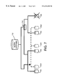
- FIG. 1 is a block diagram of a typical RAID storage implementation showing a partitioned set of disks according to the principles of this invention
- FIG. 2 is a schematic diagram of a container structure including a specialized container layer according to the principles of this invention
- FIG. 3 is a block diagram of an exemplary RAID storage configuration before data migration according to an embodiment of this invention
- FIG. 4 is a block diagram of an exemplary RAID storage configuration after the creation of a specialized morph container and associated data migration therewith according to an embodiment of this invention
- FIG. 5 is a block diagram showing the mapping of data migrating between source and destination containers during a data migration procedure in accordance with the configuration shown in FIG. 4;
- FIG. 6 is a block diagram showing the mapping of a completed data migration from the source to the destination container as begun in accordance with FIG. 5;
- FIG. 7 is a block diagram of an exemplary RAID storage configuration showing the migration of data from one configuration of a given container space back into the same space with a new configuration
- FIG. 8 is a block diagram showing the mapping of data migrating between a source container and a temporary container, during a data migration procedure in accordance with the configuration shown in FIG. 7;
- FIG. 9 is a block diagram showing the mapping of a completed data migration from the temporary container to the destination container as begun in accordance with FIG. 8 .
- FIG. 1 is a schematic block diagram of a typical computer system that is as a RAID 5 storage configuration in accordance with the present invention.
- the computer system processor 100 comprises a memory 106 and an input/output (I/O) subsystem 112 interconnected with a central processing unit (CPU) 108 .
- User applications 102 are run by the host computer.
- the memory 106 comprises storage locations addressable by the CPU 108 and I/O subsystem 112 for storing software programs and data structures.
- An operating system 104 portions of which are typically resident in the memory 106 and executed by the CPU 108 , functionally organizes the computer processor 100 by, inter alia, handling I/O operations invoked by software processes or application programs executing on the computer.
- a file system 110 may reside in the operating system 104 , such as the NT File System (NTFS) from Microsoft.
- NTFS NT File System
- the I/O subsystem 112 is, in turn, connected to a set of on-line storage devices 116 . These on-line storage devices 116 are partitioned into units of physical space.
- the operating system 104 sends I/O requests to a I/O subsystem 112 which, in turn, converts the logical addresses into physical locations in the storage devices 116 and commands the latter devices to engage in the requested storage or retrieval operations.
- the I/O subsystem 112 configures the partitions of the physical storage devices 116 into containers and stores container configuration tables in the container layer 120 of the I/O subsystem 112 .
- Container configuration enables the system administrator to partition a disk drive into one or more virtual disks.
- a container manager 118 operates in association with the I/O subsystem 112 .
- disk space is initially configured based upon a “firmware” application that comprises the RAID adapter.
- the application initializes each disk drive to include metadata, needed for operation of the disk and not directly manipulated by the host computer or user, and free space.
- containers may be created. This is typically accomplished by a user interface/utility that can be termed a “configuration wizard.” This utility can prompt the user for types/levels of RAID to be established, and the size and number of containers, as well as other known parameters.
- a container driver is established by, and within, the adapter firmware.
- the container drivers map user I/O requests to and from containers. In this manner, the user and host do not communicate directly with the containers, but rather do so through the drivers via the host communication layer and associated bus (a PCI bus for example).
- the host I/O driver only has information on so-called higher-level containers. For example, if there are defined containers 0-63, the host I/O driver may have information only on 0-23 (e.g. 0-23 are visible to the host), while 24-63 are “hidden” containers accessible only by the adapter and container drivers. Such hidden containers are employed (for example, to hide original containers) during the use of specialized containers—these specialized containers being established particularly for special procedures such as the snapshot backup operation, as known generally in the art. Other forms of data migration can be used to enable OCE processes and RAID level migration according to this invention.
- an exemplary container level structure is shown.
- a series of disk drives 202 , 204 , 206 , 208 and 210 At the base of the structure are a series of disk drives 202 , 204 , 206 , 208 and 210 .
- Each of the disk drives includes a certain amount of metadata 212 , as described above.
- Disks 202 and 204 include some amount of free disk space 214 that can be allocated for further data storage.
- Each disk 202 , 204 , 206 , 208 and 210 includes a partitioned space that is used for current data storage (e.g. respective used space 222 , 224 , 226 , 228 and 230 ).
- the used space in the various disk drives is organized, as shown into a pair of containers 240 (grouping used space 222 , 224 , 226 ) and 242 (grouping used space 228 and 230 ).
- the two containers are controlled by drivers that generate mirror configurations therein for redundancy. This level can also be termed the “primary” container level.
- the two mirror containers are, likewise, grouped into a higher level of organization that defines a “stripe” container 250 with an associated stripe driver. This level is termed a “secondary” container level.
- Primary and secondary levels are typically provided in a conventional RAID implementation, particularly where a RAID “stripe with mirrors” configuration is employed.
- a tertiary container level be established above the primary and secondary levels.
- This higher-level container exists during the contemplated data migration process, and also during that time, becomes a higher level container visible to the host.
- This tertiary container is the higher-level specialized container 260 , that forms over the secondary container 250 and also joins to specialized drivers as shown.
- FIG. 3 shows a conventional, simplified configuration 300 of RAID disk containers 302 , 304 , 306 and 308 within a primary container level 310 . These are organized within a secondary container level 312 that communicates with the host I/O drivers and other adapter controllers as described generally above.
- a specialized container is formed by an associated specialized driver within the firmware.
- container is termed the “morph” container 402 , but any identifier can be used.
- the morph container 402 is now addressed as such.
- the original configuration becomes known as the data source within the migration process to be described.
- the goal of the migration is to transfer the data from the source configuration to a new destination RAID configuration 420 , which shows a different exemplary RAID organization. In this example there is a primary container level with three containers 422 , 424 and 426 .
- FIG. 5 shows a block representation of the source container 502 , a destination container 504 , the morph container 506 .
- Each denotes a series of storage blocks (e.g. 0, 1, 2 . . . ).
- the morph container when established, takes the place of the source container as a visible I/O location. Accordingly, user/host I/O requests recognize the morph as the top-level container.
- the modified bit map (not shown) for mapping I/O typically designates the morph with a high-level number such as “1” and makes the top level of the source (formerly “1” a hidden container during the migration process.
- a further mapping structure 510 controls the movement of data between containers. Data is moved from container to container. The mapping is typically a task controlled by the specialized RAID driver.
- mapping enables the morph container 506 to become the storage site of data from the source 502 .
- the data is then moved by mapping to the destination container 504 via the morph container.
- the mapping of an exemplary DATA 0 is moved (line 516 ) from the source 502 (see dashed line 520 indicating a broken map) to the destination 404 (as indicated by a new map line 522 ).
- the movement of data is completed with all map lines 602 to the source container 502 being broken, while the new mapping of the data is made into the destination container 504 (in accordance with to map lines 604 ).
- the source container is now considered “free” and may be eliminated entirely as a space.
- the top-level container mapping (e.g. “1”) is now passed to the destination container set. This is recognized as such for further I/O purposes.
- the morph container and the source container(s) are no longer recognized by the system.
- An advantage of the migration system according to this invention is that the morph driver enables ready reconfiguration from any RAID implementation to any other implementation with relative ease, including the expansion of the storage into a greater number of containers, or contraction thereof into fewer containers.
- the container space may be directly overwritten by the migrating data.
- an implementation as shown generally in FIG. 7 may be desired, in which the data is “moved” back into essentially the same container space with a concomitant change in RAID level and removal of containers.
- original primary level container pairs 702 , 704 and 706 , 708 are organized under original secondary level container 710 .
- the morph container 712 is established with associated driver above this container structure.
- the resulting migration of data (shown in dashed-line form) causes blocks to be moved into three of the same primary level containers ( 702 A, 704 A and 706 A) while container 708 and the secondary level container 710 are eliminated. Since blocks are rewritten into the same container space, there may be conflicts and collisions between old and new data.
- the morph driver can be used to resolve any conflicts, and a further step within the mapping process is employed.
- a morph container 802 is represented. Also shown is a source container 804 , which corresponds with the original RAID implementation of FIG. 7.
- a map 806 constructed as a task, similar to that described above is also shown.
- a temporary container 808 there is provided a temporary container 808 .
- the temporary container allows data to be mapped in the interim as it is moved from the source and back to the destination, which, in this example is the same space as the source.
- the temporary container can be established by the driver arrangement when it detects that destination addresses are the same as source addresses for a particular data migration process requested by the user.
- the first data move is depicted.
- mapping of data to the source has been broken (denoted by dashed lines 810 ). Rather, the morph container map 806 now points to the temporary container 808 (mapping lines 812 ). Consequently, the mapping “moves” the data from the source blocks to the temporary container blocks as denoted by lines 814 .
- FIG. 9 shows the completed data migration.
- the source container is redesignated as the destination container 904 .
- the mapping to the temporary container 808 has been broken (denoted by dashed lines 906 ).
- a new mapping (lines 908 ) is made from the map 806 to the destination container 904 and associated movement of data occurs as denoted by lines 910 .
- the temporary container is typically arranged to transfer a portion (a block, blocks or other-sized chunk) of the entire data in a given operation.
- the movement of data may occur in a number of separate moves, each occurring through the temporary container, in turn.
- RAID drivers and associated container drivers are shown as part of the adapter firmware, they may reside at a variety of physical locations.
- the principles described herein may be implemented in hardware, software or a combination of both.
- the number of physical disk drives used to implement the teachings described herein is highly variable, and, in fact a single, sufficiently large disk drive can be employed in an alternate embodiment. Accordingly, this description is meant to be taken only by way of example, and not to otherwise limit the scope of the invention.
Abstract
Description
Claims (10)
Priority Applications (1)
| Application Number | Priority Date | Filing Date | Title |
|---|---|---|---|
| US09/465,057 US6510491B1 (en) | 1999-12-16 | 1999-12-16 | System and method for accomplishing data storage migration between raid levels |
Applications Claiming Priority (1)
| Application Number | Priority Date | Filing Date | Title |
|---|---|---|---|
| US09/465,057 US6510491B1 (en) | 1999-12-16 | 1999-12-16 | System and method for accomplishing data storage migration between raid levels |
Publications (1)
| Publication Number | Publication Date |
|---|---|
| US6510491B1 true US6510491B1 (en) | 2003-01-21 |
Family
ID=23846333
Family Applications (1)
| Application Number | Title | Priority Date | Filing Date |
|---|---|---|---|
| US09/465,057 Expired - Lifetime US6510491B1 (en) | 1999-12-16 | 1999-12-16 | System and method for accomplishing data storage migration between raid levels |
Country Status (1)
| Country | Link |
|---|---|
| US (1) | US6510491B1 (en) |
Cited By (24)
| Publication number | Priority date | Publication date | Assignee | Title |
|---|---|---|---|---|
| US6618794B1 (en) * | 2000-10-31 | 2003-09-09 | Hewlett-Packard Development Company, L.P. | System for generating a point-in-time copy of data in a data storage system |
| US6708232B2 (en) * | 2000-06-29 | 2004-03-16 | Hitachi, Ltd. | Data migration method, protocol converter and switching apparatus using it |
| US20040162940A1 (en) * | 2003-02-17 | 2004-08-19 | Ikuya Yagisawa | Storage system |
| US6813687B1 (en) * | 2000-08-25 | 2004-11-02 | Lsi Logic Corporation | Raid volume for sequential use that needs no redundancy pre-initialization |
| US20040230787A1 (en) * | 1999-04-21 | 2004-11-18 | Emc Corporation | Method and apparatus for dynamically modifying a computer system configuration |
| US20040236908A1 (en) * | 2003-05-22 | 2004-11-25 | Katsuyoshi Suzuki | Disk array apparatus and method for controlling the same |
| US20050050270A1 (en) * | 2003-08-27 | 2005-03-03 | Horn Robert L. | System and method of establishing and reconfiguring volume profiles in a storage system |
| US20050117462A1 (en) * | 2003-11-28 | 2005-06-02 | Azuma Kano | Disk array system and method for controlling disk array system |
| US20050141184A1 (en) * | 2003-12-25 | 2005-06-30 | Hiroshi Suzuki | Storage system |
| US20060161752A1 (en) * | 2005-01-18 | 2006-07-20 | Burkey Todd R | Method, apparatus and program storage device for providing adaptive, attribute driven, closed-loop storage management configuration and control |
| US20060179218A1 (en) * | 2005-02-10 | 2006-08-10 | Burkey Todd R | Method, apparatus and program storage device for providing geographically isolated failover using instant RAID swapping in mirrored virtual disks |
| US20060206660A1 (en) * | 2003-05-22 | 2006-09-14 | Hiromi Matsushige | Storage unit and circuit for shaping communication signal |
| US20060218360A1 (en) * | 2005-03-22 | 2006-09-28 | Burkey Todd R | Method, apparatus and program storage device for providing an optimized read methodology for synchronously mirrored virtual disk pairs |
| US20060255409A1 (en) * | 2004-02-04 | 2006-11-16 | Seiki Morita | Anomaly notification control in disk array |
| US20070011401A1 (en) * | 2005-07-06 | 2007-01-11 | Exavio, Inc. | System and method for adaptive operation of storage capacities of RAID systems |
| US7281104B1 (en) | 2005-03-21 | 2007-10-09 | Acronis Inc. | System and method for online data migration |
| US20070283119A1 (en) * | 2006-05-31 | 2007-12-06 | International Business Machines Corporation | System and Method for Providing Automated Storage Provisioning |
| US7454566B1 (en) * | 2005-05-02 | 2008-11-18 | Nvidia Corporation | System and method for adaptive RAID configuration |
| US20090276567A1 (en) * | 2008-04-30 | 2009-11-05 | Burkey Todd R | Compensating for write speed differences between mirroring storage devices by striping |
| US20100011176A1 (en) * | 2008-07-11 | 2010-01-14 | Burkey Todd R | Performance of binary bulk IO operations on virtual disks by interleaving |
| US20100011371A1 (en) * | 2008-07-11 | 2010-01-14 | Burkey Todd R | Performance of unary bulk IO operations on virtual disks by interleaving |
| US9513823B2 (en) | 2012-04-30 | 2016-12-06 | Hewlett Packard Enterprise Development Lp | Data migration |
| US10235053B1 (en) * | 2014-03-31 | 2019-03-19 | Emc Corporation | Method and system for using host driver for flexible allocation fast-sideways data movements |
| US20190087111A1 (en) * | 2017-09-15 | 2019-03-21 | Seagate Technology Llc | Common logical block addressing translation layer for a storage array |
Citations (12)
| Publication number | Priority date | Publication date | Assignee | Title |
|---|---|---|---|---|
| US5263154A (en) | 1992-04-20 | 1993-11-16 | International Business Machines Corporation | Method and system for incremental time zero backup copying of data |
| US5568629A (en) | 1991-12-23 | 1996-10-22 | At&T Global Information Solutions Company | Method for partitioning disk drives within a physical disk array and selectively assigning disk drive partitions into a logical disk array |
| US5675769A (en) | 1995-02-23 | 1997-10-07 | Powerquest Corporation | Method for manipulating disk partitions |
| US5721858A (en) | 1995-12-12 | 1998-02-24 | International Business Machines Corporation | Virtual memory mapping method and system for memory management of pools of logical partitions for bat and TLB entries in a data processing system |
| US5794254A (en) | 1996-12-03 | 1998-08-11 | Fairbanks Systems Group | Incremental computer file backup using a two-step comparison of first two characters in the block and a signature with pre-stored character and signature sets |
| US5835953A (en) | 1994-10-13 | 1998-11-10 | Vinca Corporation | Backup system that takes a snapshot of the locations in a mass storage device that has been identified for updating prior to updating |
| US5875457A (en) * | 1996-10-08 | 1999-02-23 | Mylex Corporation | Fault-tolerant preservation of data integrity during dynamic raid set expansion |
| US5907672A (en) | 1995-10-04 | 1999-05-25 | Stac, Inc. | System for backing up computer disk volumes with error remapping of flawed memory addresses |
| US5930831A (en) | 1995-02-23 | 1999-07-27 | Powerquest Corporation | Partition manipulation architecture supporting multiple file systems |
| US6275898B1 (en) * | 1999-05-13 | 2001-08-14 | Lsi Logic Corporation | Methods and structure for RAID level migration within a logical unit |
| US6282619B1 (en) * | 1997-07-02 | 2001-08-28 | International Business Machines Corporation | Logical drive migration for a raid adapter |
| US6304942B1 (en) * | 1999-08-09 | 2001-10-16 | Lsi Logic Corporation | Providing an upgrade path for an existing data storage system |
-
1999
- 1999-12-16 US US09/465,057 patent/US6510491B1/en not_active Expired - Lifetime
Patent Citations (12)
| Publication number | Priority date | Publication date | Assignee | Title |
|---|---|---|---|---|
| US5568629A (en) | 1991-12-23 | 1996-10-22 | At&T Global Information Solutions Company | Method for partitioning disk drives within a physical disk array and selectively assigning disk drive partitions into a logical disk array |
| US5263154A (en) | 1992-04-20 | 1993-11-16 | International Business Machines Corporation | Method and system for incremental time zero backup copying of data |
| US5835953A (en) | 1994-10-13 | 1998-11-10 | Vinca Corporation | Backup system that takes a snapshot of the locations in a mass storage device that has been identified for updating prior to updating |
| US5675769A (en) | 1995-02-23 | 1997-10-07 | Powerquest Corporation | Method for manipulating disk partitions |
| US5930831A (en) | 1995-02-23 | 1999-07-27 | Powerquest Corporation | Partition manipulation architecture supporting multiple file systems |
| US5907672A (en) | 1995-10-04 | 1999-05-25 | Stac, Inc. | System for backing up computer disk volumes with error remapping of flawed memory addresses |
| US5721858A (en) | 1995-12-12 | 1998-02-24 | International Business Machines Corporation | Virtual memory mapping method and system for memory management of pools of logical partitions for bat and TLB entries in a data processing system |
| US5875457A (en) * | 1996-10-08 | 1999-02-23 | Mylex Corporation | Fault-tolerant preservation of data integrity during dynamic raid set expansion |
| US5794254A (en) | 1996-12-03 | 1998-08-11 | Fairbanks Systems Group | Incremental computer file backup using a two-step comparison of first two characters in the block and a signature with pre-stored character and signature sets |
| US6282619B1 (en) * | 1997-07-02 | 2001-08-28 | International Business Machines Corporation | Logical drive migration for a raid adapter |
| US6275898B1 (en) * | 1999-05-13 | 2001-08-14 | Lsi Logic Corporation | Methods and structure for RAID level migration within a logical unit |
| US6304942B1 (en) * | 1999-08-09 | 2001-10-16 | Lsi Logic Corporation | Providing an upgrade path for an existing data storage system |
Non-Patent Citations (1)
| Title |
|---|
| U.S. patent application Ser. No. 08/964,304, Napolitano et al., filed Nov. 4, 1997. |
Cited By (87)
| Publication number | Priority date | Publication date | Assignee | Title |
|---|---|---|---|---|
| US6931440B1 (en) * | 1999-04-21 | 2005-08-16 | Emc Corporation | Method and apparatus for dynamically determining whether access to a resource connected to a computer has changed and determining how to access the resource with a new identifier |
| US20040230787A1 (en) * | 1999-04-21 | 2004-11-18 | Emc Corporation | Method and apparatus for dynamically modifying a computer system configuration |
| US7519696B2 (en) | 1999-04-21 | 2009-04-14 | Emc Corporation | Method and apparatus for dynamically modifying a computer system configuration |
| US6708232B2 (en) * | 2000-06-29 | 2004-03-16 | Hitachi, Ltd. | Data migration method, protocol converter and switching apparatus using it |
| US20040158652A1 (en) * | 2000-06-29 | 2004-08-12 | Kiyohiro Obara | Data migration method, protocol converter and switching apparatus using it |
| US7130954B2 (en) | 2000-06-29 | 2006-10-31 | Hitachi, Ltd. | Data migration method, protocol converter and switching apparatus using it |
| US6813687B1 (en) * | 2000-08-25 | 2004-11-02 | Lsi Logic Corporation | Raid volume for sequential use that needs no redundancy pre-initialization |
| US6618794B1 (en) * | 2000-10-31 | 2003-09-09 | Hewlett-Packard Development Company, L.P. | System for generating a point-in-time copy of data in a data storage system |
| US20050066128A1 (en) * | 2003-02-17 | 2005-03-24 | Ikuya Yagisawa | Storage system |
| US20110167220A1 (en) * | 2003-02-17 | 2011-07-07 | Hitachi, Ltd. | Storage system for holding a remaining available lifetime of a logical storage region |
| US20050066126A1 (en) * | 2003-02-17 | 2005-03-24 | Ikuya Yagisawa | Storage system |
| US20050065984A1 (en) * | 2003-02-17 | 2005-03-24 | Ikuya Yagisawa | Storage system |
| US20050050275A1 (en) * | 2003-02-17 | 2005-03-03 | Ikuya Yagisawa | Storage system |
| US20050071525A1 (en) * | 2003-02-17 | 2005-03-31 | Ikuya Yagisawa | Storage system |
| US7925830B2 (en) | 2003-02-17 | 2011-04-12 | Hitachi, Ltd. | Storage system for holding a remaining available lifetime of a logical storage region |
| US20050066078A1 (en) * | 2003-02-17 | 2005-03-24 | Ikuya Yagisawa | Storage system |
| US8370572B2 (en) | 2003-02-17 | 2013-02-05 | Hitachi, Ltd. | Storage system for holding a remaining available lifetime of a logical storage region |
| US20080172528A1 (en) * | 2003-02-17 | 2008-07-17 | Hitachi, Ltd. | Storage system |
| US7366839B2 (en) | 2003-02-17 | 2008-04-29 | Hitachi, Ltd. | Storage system |
| US7275133B2 (en) | 2003-02-17 | 2007-09-25 | Hitachi, Ltd. | Storage system |
| US7272686B2 (en) | 2003-02-17 | 2007-09-18 | Hitachi, Ltd. | Storage system |
| US7146464B2 (en) | 2003-02-17 | 2006-12-05 | Hitachi, Ltd. | Storage system |
| US20040162940A1 (en) * | 2003-02-17 | 2004-08-19 | Ikuya Yagisawa | Storage system |
| US7047354B2 (en) | 2003-02-17 | 2006-05-16 | Hitachi, Ltd. | Storage system |
| US7587548B2 (en) | 2003-05-22 | 2009-09-08 | Hitachi, Ltd. | Disk array apparatus and method for controlling the same |
| US20050149668A1 (en) * | 2003-05-22 | 2005-07-07 | Katsuyoshi Suzuki | Disk array apparatus and method for controlling the same |
| US8429342B2 (en) | 2003-05-22 | 2013-04-23 | Hitachi, Ltd. | Drive apparatus and method for controlling the same |
| US20050149669A1 (en) * | 2003-05-22 | 2005-07-07 | Katsuyoshi Suzuki | Disk array apparatus and method for controlling the same |
| US20050149670A1 (en) * | 2003-05-22 | 2005-07-07 | Katsuyoshi Suzuki | Disk array apparatus and method for controlling the same |
| US20040236908A1 (en) * | 2003-05-22 | 2004-11-25 | Katsuyoshi Suzuki | Disk array apparatus and method for controlling the same |
| US7080201B2 (en) | 2003-05-22 | 2006-07-18 | Hitachi, Ltd. | Disk array apparatus and method for controlling the same |
| US8200898B2 (en) | 2003-05-22 | 2012-06-12 | Hitachi, Ltd. | Storage apparatus and method for controlling the same |
| US8151046B2 (en) | 2003-05-22 | 2012-04-03 | Hitachi, Ltd. | Disk array apparatus and method for controlling the same |
| US20060206660A1 (en) * | 2003-05-22 | 2006-09-14 | Hiromi Matsushige | Storage unit and circuit for shaping communication signal |
| US7461203B2 (en) | 2003-05-22 | 2008-12-02 | Hitachi, Ltd. | Disk array apparatus and method for controlling the same |
| US20050149672A1 (en) * | 2003-05-22 | 2005-07-07 | Katsuyoshi Suzuki | Disk array apparatus and method for controlling the same |
| US7685362B2 (en) | 2003-05-22 | 2010-03-23 | Hitachi, Ltd. | Storage unit and circuit for shaping communication signal |
| US20050149673A1 (en) * | 2003-05-22 | 2005-07-07 | Katsuyoshi Suzuki | Disk array apparatus and method for controlling the same |
| US20090150609A1 (en) * | 2003-05-22 | 2009-06-11 | Katsuyoshi Suzuki | Disk array apparatus and method for controlling the same |
| US7523258B2 (en) | 2003-05-22 | 2009-04-21 | Hitachi, Ltd. | Disk array apparatus and method for controlling the same |
| US7480765B2 (en) | 2003-05-22 | 2009-01-20 | Hitachi, Ltd. | Storage unit and circuit for shaping communication signal |
| US20050149674A1 (en) * | 2003-05-22 | 2005-07-07 | Katsuyoshi Suzuki | Disk array apparatus and method for controlling the same |
| US20080301365A1 (en) * | 2003-05-22 | 2008-12-04 | Hiromi Matsushige | Storage unit and circuit for shaping communication signal |
| US20050149671A1 (en) * | 2003-05-22 | 2005-07-07 | Katsuyoshi Suzuki | Disk array apparatus and method for controlling the same |
| US7287121B2 (en) | 2003-08-27 | 2007-10-23 | Aristos Logic Corporation | System and method of establishing and reconfiguring volume profiles in a storage system |
| US20050050270A1 (en) * | 2003-08-27 | 2005-03-03 | Horn Robert L. | System and method of establishing and reconfiguring volume profiles in a storage system |
| US7203135B2 (en) | 2003-11-28 | 2007-04-10 | Hitachi, Ltd. | Disk array system and method for controlling disk array system |
| US7057981B2 (en) | 2003-11-28 | 2006-06-06 | Hitachi, Ltd. | Disk array system and method for controlling disk array system |
| US20050120264A1 (en) * | 2003-11-28 | 2005-06-02 | Azuma Kano | Disk array system and method for controlling disk array system |
| US20050117468A1 (en) * | 2003-11-28 | 2005-06-02 | Azuma Kano | Disk array system and method of controlling disk array system |
| US7865665B2 (en) | 2003-11-28 | 2011-01-04 | Hitachi, Ltd. | Storage system for checking data coincidence between a cache memory and a disk drive |
| US7447121B2 (en) | 2003-11-28 | 2008-11-04 | Hitachi, Ltd. | Disk array system |
| US7453774B2 (en) | 2003-11-28 | 2008-11-18 | Hitachi, Ltd. | Disk array system |
| US8468300B2 (en) | 2003-11-28 | 2013-06-18 | Hitachi, Ltd. | Storage system having plural controllers and an expansion housing with drive units |
| US20050154942A1 (en) * | 2003-11-28 | 2005-07-14 | Azuma Kano | Disk array system and method for controlling disk array system |
| US20050120263A1 (en) * | 2003-11-28 | 2005-06-02 | Azuma Kano | Disk array system and method for controlling disk array system |
| US7200074B2 (en) | 2003-11-28 | 2007-04-03 | Hitachi, Ltd. | Disk array system and method for controlling disk array system |
| US20050117462A1 (en) * | 2003-11-28 | 2005-06-02 | Azuma Kano | Disk array system and method for controlling disk array system |
| US20070170782A1 (en) * | 2003-12-25 | 2007-07-26 | Hiroshi Suzuki | Storage system |
| US7423354B2 (en) | 2003-12-25 | 2008-09-09 | Hitachi, Ltd. | Storage system |
| US20050141184A1 (en) * | 2003-12-25 | 2005-06-30 | Hiroshi Suzuki | Storage system |
| US20070063587A1 (en) * | 2003-12-25 | 2007-03-22 | Hiroshi Suzuki | Storage system |
| US7671485B2 (en) | 2003-12-25 | 2010-03-02 | Hitachi, Ltd. | Storage system |
| US8015442B2 (en) | 2004-02-04 | 2011-09-06 | Hitachi, Ltd. | Anomaly notification control in disk array |
| US20060255409A1 (en) * | 2004-02-04 | 2006-11-16 | Seiki Morita | Anomaly notification control in disk array |
| US7457981B2 (en) | 2004-02-04 | 2008-11-25 | Hitachi, Ltd. | Anomaly notification control in disk array |
| US8365013B2 (en) | 2004-02-04 | 2013-01-29 | Hitachi, Ltd. | Anomaly notification control in disk array |
| US7475283B2 (en) | 2004-02-04 | 2009-01-06 | Hitachi, Ltd. | Anomaly notification control in disk array |
| US7823010B2 (en) | 2004-02-04 | 2010-10-26 | Hitachi, Ltd. | Anomaly notification control in disk array |
| US20060161752A1 (en) * | 2005-01-18 | 2006-07-20 | Burkey Todd R | Method, apparatus and program storage device for providing adaptive, attribute driven, closed-loop storage management configuration and control |
| US20060179218A1 (en) * | 2005-02-10 | 2006-08-10 | Burkey Todd R | Method, apparatus and program storage device for providing geographically isolated failover using instant RAID swapping in mirrored virtual disks |
| US7941602B2 (en) * | 2005-02-10 | 2011-05-10 | Xiotech Corporation | Method, apparatus and program storage device for providing geographically isolated failover using instant RAID swapping in mirrored virtual disks |
| US7281104B1 (en) | 2005-03-21 | 2007-10-09 | Acronis Inc. | System and method for online data migration |
| US20060218360A1 (en) * | 2005-03-22 | 2006-09-28 | Burkey Todd R | Method, apparatus and program storage device for providing an optimized read methodology for synchronously mirrored virtual disk pairs |
| US7454566B1 (en) * | 2005-05-02 | 2008-11-18 | Nvidia Corporation | System and method for adaptive RAID configuration |
| US7512736B1 (en) * | 2005-05-02 | 2009-03-31 | Nvidia Corporation | System and method for adaptive raid configuration |
| US7774542B2 (en) * | 2005-07-06 | 2010-08-10 | Ji Zhang | System and method for adaptive operation of storage capacities of RAID systems |
| US20070011401A1 (en) * | 2005-07-06 | 2007-01-11 | Exavio, Inc. | System and method for adaptive operation of storage capacities of RAID systems |
| US7587570B2 (en) * | 2006-05-31 | 2009-09-08 | International Business Machines Corporation | System and method for providing automated storage provisioning |
| US20070283119A1 (en) * | 2006-05-31 | 2007-12-06 | International Business Machines Corporation | System and Method for Providing Automated Storage Provisioning |
| US7971013B2 (en) | 2008-04-30 | 2011-06-28 | Xiotech Corporation | Compensating for write speed differences between mirroring storage devices by striping |
| US20090276567A1 (en) * | 2008-04-30 | 2009-11-05 | Burkey Todd R | Compensating for write speed differences between mirroring storage devices by striping |
| US20100011176A1 (en) * | 2008-07-11 | 2010-01-14 | Burkey Todd R | Performance of binary bulk IO operations on virtual disks by interleaving |
| US20100011371A1 (en) * | 2008-07-11 | 2010-01-14 | Burkey Todd R | Performance of unary bulk IO operations on virtual disks by interleaving |
| US9513823B2 (en) | 2012-04-30 | 2016-12-06 | Hewlett Packard Enterprise Development Lp | Data migration |
| US10235053B1 (en) * | 2014-03-31 | 2019-03-19 | Emc Corporation | Method and system for using host driver for flexible allocation fast-sideways data movements |
| US20190087111A1 (en) * | 2017-09-15 | 2019-03-21 | Seagate Technology Llc | Common logical block addressing translation layer for a storage array |
Similar Documents
| Publication | Publication Date | Title |
|---|---|---|
| US6510491B1 (en) | System and method for accomplishing data storage migration between raid levels | |
| US6341341B1 (en) | System and method for disk control with snapshot feature including read-write snapshot half | |
| US7676628B1 (en) | Methods, systems, and computer program products for providing access to shared storage by computing grids and clusters with large numbers of nodes | |
| US6460054B1 (en) | System and method for data storage archive bit update after snapshot backup | |
| US5129088A (en) | Data processing method to create virtual disks from non-contiguous groups of logically contiguous addressable blocks of direct access storage device | |
| US5809279A (en) | Computer system including a device with a plurality of identifiers | |
| US7836272B1 (en) | Methods and apparatus for interfacing to a data storage system | |
| CA2355546C (en) | Mirroring agent accessible to remote host computers, and accessing remote data-storage devices, via a communications medium | |
| US7340640B1 (en) | System and method for recoverable mirroring in a storage environment employing asymmetric distributed block virtualization | |
| US6275892B1 (en) | System for on-line disk system configuration | |
| US6633962B1 (en) | Method, system, program, and data structures for restricting host access to a storage space | |
| US20060047926A1 (en) | Managing multiple snapshot copies of data | |
| US7337288B2 (en) | Instant refresh of a data volume copy | |
| US6041366A (en) | System and method for dynamic specification of input/output attributes | |
| US6915403B2 (en) | Apparatus and method for logical volume reallocation | |
| EP1796004A1 (en) | Storage system and data processing system | |
| US6081879A (en) | Data processing system and virtual partitioning method for creating logical multi-level units of online storage | |
| US9557933B1 (en) | Selective migration of physical data | |
| JP2004127294A (en) | Virtual storage system and its operation method | |
| JP2007133471A (en) | Storage device, and method for restoring snapshot | |
| KR20100077156A (en) | Thin provisioning migration and scrubbing | |
| KR20010007111A (en) | Data processor storage systems with dynamic resynchronization of mirrored logical data volumes subsequent to a storage system failure | |
| US20100088279A1 (en) | Information processing apparatus and operation method thereof | |
| US6105118A (en) | System and method for selecting which data copy to read in an information handling system | |
| US7685129B1 (en) | Dynamic data set migration |
Legal Events
| Date | Code | Title | Description |
|---|---|---|---|
| AS | Assignment |
Owner name: ADAPTEC, INC., CALIFORNIA Free format text: ASSIGNMENT OF ASSIGNORS INTEREST;ASSIGNORS:FRANKLIN, CHRIS R.;ARNOTT, RANDY M.;WONG, JEFFREY T.;REEL/FRAME:010644/0432 Effective date: 20000322 |
|
| STCF | Information on status: patent grant |
Free format text: PATENTED CASE |
|
| FPAY | Fee payment |
Year of fee payment: 4 |
|
| REMI | Maintenance fee reminder mailed | ||
| FPAY | Fee payment |
Year of fee payment: 8 |
|
| SULP | Surcharge for late payment |
Year of fee payment: 7 |
|
| AS | Assignment |
Owner name: PMC-SIERRA, INC., CALIFORNIA Free format text: ASSIGNMENT OF ASSIGNORS INTEREST;ASSIGNOR:ADAPTEC, INC.;REEL/FRAME:030899/0567 Effective date: 20100608 |
|
| AS | Assignment |
Owner name: BANK OF AMERICA, N.A., NORTH CAROLINA Free format text: SECURITY INTEREST IN PATENTS;ASSIGNORS:PMC-SIERRA, INC.;PMC-SIERRA US, INC.;WINTEGRA, INC.;REEL/FRAME:030947/0710 Effective date: 20130802 |
|
| FPAY | Fee payment |
Year of fee payment: 12 |
|
| AS | Assignment |
Owner name: PMC-SIERRA, INC., CALIFORNIA Free format text: RELEASE BY SECURED PARTY;ASSIGNOR:BANK OF AMERICA, N.A.;REEL/FRAME:037675/0129 Effective date: 20160115 Owner name: PMC-SIERRA US, INC., CALIFORNIA Free format text: RELEASE BY SECURED PARTY;ASSIGNOR:BANK OF AMERICA, N.A.;REEL/FRAME:037675/0129 Effective date: 20160115 Owner name: WINTEGRA, INC., CALIFORNIA Free format text: RELEASE BY SECURED PARTY;ASSIGNOR:BANK OF AMERICA, N.A.;REEL/FRAME:037675/0129 Effective date: 20160115 |
|
| AS | Assignment |
Owner name: MORGAN STANLEY SENIOR FUNDING, INC., NEW YORK Free format text: PATENT SECURITY AGREEMENT;ASSIGNORS:MICROSEMI STORAGE SOLUTIONS, INC. (F/K/A PMC-SIERRA, INC.);MICROSEMI STORAGE SOLUTIONS (U.S.), INC. (F/K/A PMC-SIERRA US, INC.);REEL/FRAME:037689/0719 Effective date: 20160115 |
|
| AS | Assignment |
Owner name: MICROSEMI STORAGE SOLUTIONS, INC., CALIFORNIA Free format text: RELEASE BY SECURED PARTY;ASSIGNOR:MORGAN STANLEY SENIOR FUNDING, INC.;REEL/FRAME:046251/0271 Effective date: 20180529 Owner name: MICROSEMI STORAGE SOLUTIONS (U.S.), INC., CALIFORN Free format text: RELEASE BY SECURED PARTY;ASSIGNOR:MORGAN STANLEY SENIOR FUNDING, INC.;REEL/FRAME:046251/0271 Effective date: 20180529 |
|
| AS | Assignment |
Owner name: JPMORGAN CHASE BANK, N.A., AS ADMINISTRATIVE AGENT, ILLINOIS Free format text: SECURITY INTEREST;ASSIGNORS:MICROCHIP TECHNOLOGY INCORPORATED;SILICON STORAGE TECHNOLOGY, INC.;ATMEL CORPORATION;AND OTHERS;REEL/FRAME:046426/0001 Effective date: 20180529 Owner name: JPMORGAN CHASE BANK, N.A., AS ADMINISTRATIVE AGENT Free format text: SECURITY INTEREST;ASSIGNORS:MICROCHIP TECHNOLOGY INCORPORATED;SILICON STORAGE TECHNOLOGY, INC.;ATMEL CORPORATION;AND OTHERS;REEL/FRAME:046426/0001 Effective date: 20180529 |
|
| AS | Assignment |
Owner name: WELLS FARGO BANK, NATIONAL ASSOCIATION, AS NOTES COLLATERAL AGENT, CALIFORNIA Free format text: SECURITY INTEREST;ASSIGNORS:MICROCHIP TECHNOLOGY INCORPORATED;SILICON STORAGE TECHNOLOGY, INC.;ATMEL CORPORATION;AND OTHERS;REEL/FRAME:047103/0206 Effective date: 20180914 Owner name: WELLS FARGO BANK, NATIONAL ASSOCIATION, AS NOTES C Free format text: SECURITY INTEREST;ASSIGNORS:MICROCHIP TECHNOLOGY INCORPORATED;SILICON STORAGE TECHNOLOGY, INC.;ATMEL CORPORATION;AND OTHERS;REEL/FRAME:047103/0206 Effective date: 20180914 |
|
| AS | Assignment |
Owner name: JPMORGAN CHASE BANK, N.A., AS ADMINISTRATIVE AGENT, DELAWARE Free format text: SECURITY INTEREST;ASSIGNORS:MICROCHIP TECHNOLOGY INC.;SILICON STORAGE TECHNOLOGY, INC.;ATMEL CORPORATION;AND OTHERS;REEL/FRAME:053311/0305 Effective date: 20200327 |
|
| AS | Assignment |
Owner name: MICROSEMI CORPORATION, CALIFORNIA Free format text: RELEASE BY SECURED PARTY;ASSIGNOR:JPMORGAN CHASE BANK, N.A, AS ADMINISTRATIVE AGENT;REEL/FRAME:053466/0011 Effective date: 20200529 Owner name: SILICON STORAGE TECHNOLOGY, INC., ARIZONA Free format text: RELEASE BY SECURED PARTY;ASSIGNOR:JPMORGAN CHASE BANK, N.A, AS ADMINISTRATIVE AGENT;REEL/FRAME:053466/0011 Effective date: 20200529 Owner name: MICROCHIP TECHNOLOGY INC., ARIZONA Free format text: RELEASE BY SECURED PARTY;ASSIGNOR:JPMORGAN CHASE BANK, N.A, AS ADMINISTRATIVE AGENT;REEL/FRAME:053466/0011 Effective date: 20200529 Owner name: ATMEL CORPORATION, ARIZONA Free format text: RELEASE BY SECURED PARTY;ASSIGNOR:JPMORGAN CHASE BANK, N.A, AS ADMINISTRATIVE AGENT;REEL/FRAME:053466/0011 Effective date: 20200529 Owner name: MICROSEMI STORAGE SOLUTIONS, INC., ARIZONA Free format text: RELEASE BY SECURED PARTY;ASSIGNOR:JPMORGAN CHASE BANK, N.A, AS ADMINISTRATIVE AGENT;REEL/FRAME:053466/0011 Effective date: 20200529 |
|
| AS | Assignment |
Owner name: WELLS FARGO BANK, NATIONAL ASSOCIATION, MINNESOTA Free format text: SECURITY INTEREST;ASSIGNORS:MICROCHIP TECHNOLOGY INC.;SILICON STORAGE TECHNOLOGY, INC.;ATMEL CORPORATION;AND OTHERS;REEL/FRAME:053468/0705 Effective date: 20200529 |
|
| AS | Assignment |
Owner name: WELLS FARGO BANK, NATIONAL ASSOCIATION, AS COLLATERAL AGENT, MINNESOTA Free format text: SECURITY INTEREST;ASSIGNORS:MICROCHIP TECHNOLOGY INCORPORATED;SILICON STORAGE TECHNOLOGY, INC.;ATMEL CORPORATION;AND OTHERS;REEL/FRAME:055671/0612 Effective date: 20201217 |
|
| AS | Assignment |
Owner name: MICROSEMI STORAGE SOLUTIONS, INC., ARIZONA Free format text: RELEASE BY SECURED PARTY;ASSIGNOR:JPMORGAN CHASE BANK, N.A., AS ADMINISTRATIVE AGENT;REEL/FRAME:059333/0222 Effective date: 20220218 Owner name: MICROSEMI CORPORATION, ARIZONA Free format text: RELEASE BY SECURED PARTY;ASSIGNOR:JPMORGAN CHASE BANK, N.A., AS ADMINISTRATIVE AGENT;REEL/FRAME:059333/0222 Effective date: 20220218 Owner name: ATMEL CORPORATION, ARIZONA Free format text: RELEASE BY SECURED PARTY;ASSIGNOR:JPMORGAN CHASE BANK, N.A., AS ADMINISTRATIVE AGENT;REEL/FRAME:059333/0222 Effective date: 20220218 Owner name: SILICON STORAGE TECHNOLOGY, INC., ARIZONA Free format text: RELEASE BY SECURED PARTY;ASSIGNOR:JPMORGAN CHASE BANK, N.A., AS ADMINISTRATIVE AGENT;REEL/FRAME:059333/0222 Effective date: 20220218 Owner name: MICROCHIP TECHNOLOGY INCORPORATED, ARIZONA Free format text: RELEASE BY SECURED PARTY;ASSIGNOR:JPMORGAN CHASE BANK, N.A., AS ADMINISTRATIVE AGENT;REEL/FRAME:059333/0222 Effective date: 20220218 |
|
| AS | Assignment |
Owner name: MICROSEMI STORAGE SOLUTIONS, INC., ARIZONA Free format text: RELEASE BY SECURED PARTY;ASSIGNOR:WELLS FARGO BANK, NATIONAL ASSOCIATION, AS NOTES COLLATERAL AGENT;REEL/FRAME:059358/0001 Effective date: 20220228 Owner name: MICROSEMI CORPORATION, ARIZONA Free format text: RELEASE BY SECURED PARTY;ASSIGNOR:WELLS FARGO BANK, NATIONAL ASSOCIATION, AS NOTES COLLATERAL AGENT;REEL/FRAME:059358/0001 Effective date: 20220228 Owner name: ATMEL CORPORATION, ARIZONA Free format text: RELEASE BY SECURED PARTY;ASSIGNOR:WELLS FARGO BANK, NATIONAL ASSOCIATION, AS NOTES COLLATERAL AGENT;REEL/FRAME:059358/0001 Effective date: 20220228 Owner name: SILICON STORAGE TECHNOLOGY, INC., ARIZONA Free format text: RELEASE BY SECURED PARTY;ASSIGNOR:WELLS FARGO BANK, NATIONAL ASSOCIATION, AS NOTES COLLATERAL AGENT;REEL/FRAME:059358/0001 Effective date: 20220228 Owner name: MICROCHIP TECHNOLOGY INCORPORATED, ARIZONA Free format text: RELEASE BY SECURED PARTY;ASSIGNOR:WELLS FARGO BANK, NATIONAL ASSOCIATION, AS NOTES COLLATERAL AGENT;REEL/FRAME:059358/0001 Effective date: 20220228 |
|
| AS | Assignment |
Owner name: MICROSEMI STORAGE SOLUTIONS, INC., ARIZONA Free format text: RELEASE BY SECURED PARTY;ASSIGNOR:WELLS FARGO BANK, NATIONAL ASSOCIATION, AS NOTES COLLATERAL AGENT;REEL/FRAME:059863/0400 Effective date: 20220228 Owner name: MICROSEMI CORPORATION, ARIZONA Free format text: RELEASE BY SECURED PARTY;ASSIGNOR:WELLS FARGO BANK, NATIONAL ASSOCIATION, AS NOTES COLLATERAL AGENT;REEL/FRAME:059863/0400 Effective date: 20220228 Owner name: ATMEL CORPORATION, ARIZONA Free format text: RELEASE BY SECURED PARTY;ASSIGNOR:WELLS FARGO BANK, NATIONAL ASSOCIATION, AS NOTES COLLATERAL AGENT;REEL/FRAME:059863/0400 Effective date: 20220228 Owner name: SILICON STORAGE TECHNOLOGY, INC., ARIZONA Free format text: RELEASE BY SECURED PARTY;ASSIGNOR:WELLS FARGO BANK, NATIONAL ASSOCIATION, AS NOTES COLLATERAL AGENT;REEL/FRAME:059863/0400 Effective date: 20220228 Owner name: MICROCHIP TECHNOLOGY INCORPORATED, ARIZONA Free format text: RELEASE BY SECURED PARTY;ASSIGNOR:WELLS FARGO BANK, NATIONAL ASSOCIATION, AS NOTES COLLATERAL AGENT;REEL/FRAME:059863/0400 Effective date: 20220228 |
|
| AS | Assignment |
Owner name: MICROSEMI STORAGE SOLUTIONS, INC., ARIZONA Free format text: RELEASE BY SECURED PARTY;ASSIGNOR:WELLS FARGO BANK, NATIONAL ASSOCIATION, AS NOTES COLLATERAL AGENT;REEL/FRAME:059363/0001 Effective date: 20220228 Owner name: MICROSEMI CORPORATION, ARIZONA Free format text: RELEASE BY SECURED PARTY;ASSIGNOR:WELLS FARGO BANK, NATIONAL ASSOCIATION, AS NOTES COLLATERAL AGENT;REEL/FRAME:059363/0001 Effective date: 20220228 Owner name: ATMEL CORPORATION, ARIZONA Free format text: RELEASE BY SECURED PARTY;ASSIGNOR:WELLS FARGO BANK, NATIONAL ASSOCIATION, AS NOTES COLLATERAL AGENT;REEL/FRAME:059363/0001 Effective date: 20220228 Owner name: SILICON STORAGE TECHNOLOGY, INC., ARIZONA Free format text: RELEASE BY SECURED PARTY;ASSIGNOR:WELLS FARGO BANK, NATIONAL ASSOCIATION, AS NOTES COLLATERAL AGENT;REEL/FRAME:059363/0001 Effective date: 20220228 Owner name: MICROCHIP TECHNOLOGY INCORPORATED, ARIZONA Free format text: RELEASE BY SECURED PARTY;ASSIGNOR:WELLS FARGO BANK, NATIONAL ASSOCIATION, AS NOTES COLLATERAL AGENT;REEL/FRAME:059363/0001 Effective date: 20220228 |
|
| AS | Assignment |
Owner name: MICROSEMI STORAGE SOLUTIONS, INC., ARIZONA Free format text: RELEASE BY SECURED PARTY;ASSIGNOR:WELLS FARGO BANK, NATIONAL ASSOCIATION, AS NOTES COLLATERAL AGENT;REEL/FRAME:060894/0437 Effective date: 20220228 Owner name: MICROSEMI CORPORATION, ARIZONA Free format text: RELEASE BY SECURED PARTY;ASSIGNOR:WELLS FARGO BANK, NATIONAL ASSOCIATION, AS NOTES COLLATERAL AGENT;REEL/FRAME:060894/0437 Effective date: 20220228 Owner name: ATMEL CORPORATION, ARIZONA Free format text: RELEASE BY SECURED PARTY;ASSIGNOR:WELLS FARGO BANK, NATIONAL ASSOCIATION, AS NOTES COLLATERAL AGENT;REEL/FRAME:060894/0437 Effective date: 20220228 Owner name: SILICON STORAGE TECHNOLOGY, INC., ARIZONA Free format text: RELEASE BY SECURED PARTY;ASSIGNOR:WELLS FARGO BANK, NATIONAL ASSOCIATION, AS NOTES COLLATERAL AGENT;REEL/FRAME:060894/0437 Effective date: 20220228 Owner name: MICROCHIP TECHNOLOGY INCORPORATED, ARIZONA Free format text: RELEASE BY SECURED PARTY;ASSIGNOR:WELLS FARGO BANK, NATIONAL ASSOCIATION, AS NOTES COLLATERAL AGENT;REEL/FRAME:060894/0437 Effective date: 20220228 |