US6151891A - Heat exchanger for a motor vehicle exhaust - Google Patents
Heat exchanger for a motor vehicle exhaust Download PDFInfo
- Publication number
- US6151891A US6151891A US09/158,711 US15871198A US6151891A US 6151891 A US6151891 A US 6151891A US 15871198 A US15871198 A US 15871198A US 6151891 A US6151891 A US 6151891A
- Authority
- US
- United States
- Prior art keywords
- tubular body
- conduit
- outer tubular
- fluid
- inner tubular
- Prior art date
- Legal status (The legal status is an assumption and is not a legal conclusion. Google has not performed a legal analysis and makes no representation as to the accuracy of the status listed.)
- Expired - Fee Related
Links
Images

Classifications
-
- F—MECHANICAL ENGINEERING; LIGHTING; HEATING; WEAPONS; BLASTING
- F01—MACHINES OR ENGINES IN GENERAL; ENGINE PLANTS IN GENERAL; STEAM ENGINES
- F01N—GAS-FLOW SILENCERS OR EXHAUST APPARATUS FOR MACHINES OR ENGINES IN GENERAL; GAS-FLOW SILENCERS OR EXHAUST APPARATUS FOR INTERNAL COMBUSTION ENGINES
- F01N5/00—Exhaust or silencing apparatus combined or associated with devices profiting from exhaust energy
- F01N5/02—Exhaust or silencing apparatus combined or associated with devices profiting from exhaust energy the devices using heat
-
- F—MECHANICAL ENGINEERING; LIGHTING; HEATING; WEAPONS; BLASTING
- F01—MACHINES OR ENGINES IN GENERAL; ENGINE PLANTS IN GENERAL; STEAM ENGINES
- F01N—GAS-FLOW SILENCERS OR EXHAUST APPARATUS FOR MACHINES OR ENGINES IN GENERAL; GAS-FLOW SILENCERS OR EXHAUST APPARATUS FOR INTERNAL COMBUSTION ENGINES
- F01N3/00—Exhaust or silencing apparatus having means for purifying, rendering innocuous, or otherwise treating exhaust
- F01N3/02—Exhaust or silencing apparatus having means for purifying, rendering innocuous, or otherwise treating exhaust for cooling, or for removing solid constituents of, exhaust
- F01N3/04—Exhaust or silencing apparatus having means for purifying, rendering innocuous, or otherwise treating exhaust for cooling, or for removing solid constituents of, exhaust using liquids
- F01N3/043—Exhaust or silencing apparatus having means for purifying, rendering innocuous, or otherwise treating exhaust for cooling, or for removing solid constituents of, exhaust using liquids without contact between liquid and exhaust gases
-
- F—MECHANICAL ENGINEERING; LIGHTING; HEATING; WEAPONS; BLASTING
- F01—MACHINES OR ENGINES IN GENERAL; ENGINE PLANTS IN GENERAL; STEAM ENGINES
- F01N—GAS-FLOW SILENCERS OR EXHAUST APPARATUS FOR MACHINES OR ENGINES IN GENERAL; GAS-FLOW SILENCERS OR EXHAUST APPARATUS FOR INTERNAL COMBUSTION ENGINES
- F01N3/00—Exhaust or silencing apparatus having means for purifying, rendering innocuous, or otherwise treating exhaust
- F01N3/08—Exhaust or silencing apparatus having means for purifying, rendering innocuous, or otherwise treating exhaust for rendering innocuous
- F01N3/10—Exhaust or silencing apparatus having means for purifying, rendering innocuous, or otherwise treating exhaust for rendering innocuous by thermal or catalytic conversion of noxious components of exhaust
- F01N3/24—Exhaust or silencing apparatus having means for purifying, rendering innocuous, or otherwise treating exhaust for rendering innocuous by thermal or catalytic conversion of noxious components of exhaust characterised by constructional aspects of converting apparatus
- F01N3/28—Construction of catalytic reactors
- F01N3/2882—Catalytic reactors combined or associated with other devices, e.g. exhaust silencers or other exhaust purification devices
-
- F—MECHANICAL ENGINEERING; LIGHTING; HEATING; WEAPONS; BLASTING
- F28—HEAT EXCHANGE IN GENERAL
- F28D—HEAT-EXCHANGE APPARATUS, NOT PROVIDED FOR IN ANOTHER SUBCLASS, IN WHICH THE HEAT-EXCHANGE MEDIA DO NOT COME INTO DIRECT CONTACT
- F28D7/00—Heat-exchange apparatus having stationary tubular conduit assemblies for both heat-exchange media, the media being in contact with different sides of a conduit wall
- F28D7/02—Heat-exchange apparatus having stationary tubular conduit assemblies for both heat-exchange media, the media being in contact with different sides of a conduit wall the conduits being helically coiled
- F28D7/024—Heat-exchange apparatus having stationary tubular conduit assemblies for both heat-exchange media, the media being in contact with different sides of a conduit wall the conduits being helically coiled the conduits of only one medium being helically coiled tubes, the coils having a cylindrical configuration
-
- F—MECHANICAL ENGINEERING; LIGHTING; HEATING; WEAPONS; BLASTING
- F01—MACHINES OR ENGINES IN GENERAL; ENGINE PLANTS IN GENERAL; STEAM ENGINES
- F01N—GAS-FLOW SILENCERS OR EXHAUST APPARATUS FOR MACHINES OR ENGINES IN GENERAL; GAS-FLOW SILENCERS OR EXHAUST APPARATUS FOR INTERNAL COMBUSTION ENGINES
- F01N2240/00—Combination or association of two or more different exhaust treating devices, or of at least one such device with an auxiliary device, not covered by indexing codes F01N2230/00 or F01N2250/00, one of the devices being
- F01N2240/02—Combination or association of two or more different exhaust treating devices, or of at least one such device with an auxiliary device, not covered by indexing codes F01N2230/00 or F01N2250/00, one of the devices being a heat exchanger
-
- Y—GENERAL TAGGING OF NEW TECHNOLOGICAL DEVELOPMENTS; GENERAL TAGGING OF CROSS-SECTIONAL TECHNOLOGIES SPANNING OVER SEVERAL SECTIONS OF THE IPC; TECHNICAL SUBJECTS COVERED BY FORMER USPC CROSS-REFERENCE ART COLLECTIONS [XRACs] AND DIGESTS
- Y02—TECHNOLOGIES OR APPLICATIONS FOR MITIGATION OR ADAPTATION AGAINST CLIMATE CHANGE
- Y02A—TECHNOLOGIES FOR ADAPTATION TO CLIMATE CHANGE
- Y02A50/00—TECHNOLOGIES FOR ADAPTATION TO CLIMATE CHANGE in human health protection, e.g. against extreme weather
- Y02A50/20—Air quality improvement or preservation, e.g. vehicle emission control or emission reduction by using catalytic converters
-
- Y—GENERAL TAGGING OF NEW TECHNOLOGICAL DEVELOPMENTS; GENERAL TAGGING OF CROSS-SECTIONAL TECHNOLOGIES SPANNING OVER SEVERAL SECTIONS OF THE IPC; TECHNICAL SUBJECTS COVERED BY FORMER USPC CROSS-REFERENCE ART COLLECTIONS [XRACs] AND DIGESTS
- Y02—TECHNOLOGIES OR APPLICATIONS FOR MITIGATION OR ADAPTATION AGAINST CLIMATE CHANGE
- Y02T—CLIMATE CHANGE MITIGATION TECHNOLOGIES RELATED TO TRANSPORTATION
- Y02T10/00—Road transport of goods or passengers
- Y02T10/10—Internal combustion engine [ICE] based vehicles
- Y02T10/12—Improving ICE efficiencies
Definitions
- the present invention relates to a heat exchanger for motor vehicle exhaust.
- the conduit of the spiral coil has an inlet end and an outlet end, whereby fluid is circulated through the coil.
- An exhaust pipe connection is provided at each of the first end and the second end of the outer tubular body, whereby exhaust from an exhaust pipe is diverted through the interior cavity of the outer tubular body.
- each side of the spiral transfer coil is exposed to exhaust gases which serves to improve the heat transfer rate.
- the spiral baffle slows down the axial flow of exhaust gases, thereby increasing the time over which heat transfer can take place. This feature is of greater importance with diesel engines, where the heat of the exhaust gases is not as extreme as with gasoline engines.
- lubricant and coolant are both sensitive to heat. If they are heated above threshold temperatures they start to deteriorate. Even more beneficial results may, therefore, be obtained when a temperature sensor coupled to a temperature actuated control valve is provided on the closed loop fluid circulation conduit. The control valve is closed to stop flow through the heat exchanger upon the temperature of fluid in the closed loop circulation conduit as sensed by the temperature sensor exceeding a preset temperature threshold actuation temperature of the control valve.
- beneficial results may be obtained through the use of the combination, as described above, when the control valve closes there is a danger that fluid may be trapped within the heat exchanger. Even more beneficial results may, therefore, be obtained when a pump is connected to the outlet end of the conduit forming the spiral coil, whereby fluid is pumped from the spiral coil after the control valve has closed to stop further flow through the heat exchanger.
- beneficial results may be obtained through the use of the combination, as described above, heat results in expansion of most fluids. Even more beneficial results may, therefore, be obtained when an overflow drain line is connected to the closed loop fluid circulation conduit, whereby excess fluid is diverted from said closed loop fluid circulation conduit. It is preferred that an overflow container is connected to a remote end of the drain line to maintain the integrity of the closed loop system and prevent environmental contamination.
- beneficial results may be obtained through the use of the combination, as described above, should the pump fail and fluid become trapped within the heat exchanger pressure in the closed loop circulation conduit will rise. Even more beneficial results may, therefore, be obtained when a pressure relief valve is provided on the closed loop fluid circulation conduit thereby providing relief against pressure build up within said closed loop fluid circulation conduit.
- beneficial results may be obtained through the use of the combination, as described above, there are various places along the exhaust system where the heat exchanger can be positioned. The most extreme heat problem in the exhaust system tends to be at the catalytic converter. Even more beneficial results may, therefore, be obtained when the exhaust system includes a catalytic converter and the heat exchanger is connected to the exhaust system downstream or and immediately adjacent to the catalytic converter.
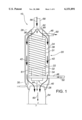
- FIG. 1 is a schematic diagram of a first embodiment heat exchanger for a motor vehicle exhaust constructed in accordance with the teachings of the present invention combined in combination with a motor vehicle exhaust.
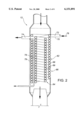
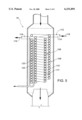
- FIG. 2 is side elevation, in section, of a second embodiment of heat exchanger.
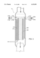
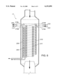
- FIG. 3 is a side elevation, in section, of a third embodiment of heat exchanger.
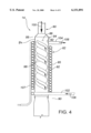
- FIG. 4 is a side elevation, in section, of a fourth embodiment of heat exchanger.
- FIG. 5 is a side elevation, in section, of a fifth embodiment of a heat exchanger.
- FIG. 6 is a side elevation, in sedtion, of a sixth embodiment of a heat exchanger.
- FIG. 7 is a schematic for a plurality of exhause pipes useful with the heat exchangers of the present invention.
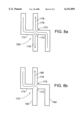
- FIG. 8 is a plan view of exhause pipes useful in the schematic of FIG. 7.
- a first embodiment, generally identified by reference numeral 10, will be described with reference to FIG. 1.
- a second embodiment, generally identified by reference numeral 12, will be described with reference to FIG. 2.
- a third embodiment, generally identified by reference numeral 13, will be described with reference to FIG. 3.
- a fourth embodiment, generally identified by reference numeral 14, will be described with reference to FIG. 4.
- a fifth embodiment, generally identified by reference numeral 16, will be described with reference to FIG. 5.
- a sixth embodiment, generally identified by reference numeral 17, will be described with reference to FIG. 6.
- first embodiment of heat exchanger 10 for a motor vehicle exhaust comprises an outer tubular body 20 and an inner tubular body 22.
- Outer tubular body 20 has peripheral sidewalls 24, an interior cavity 26, a first end 28 and a second end 30.
- Inner tubular body 22 has fluid impervious sidewalls 31 formed out of a single length of conduit wound in a spiral coil 32 which has an exterior surface 34 and an interior surface 36.
- Inner tubular body 22 is disposed within the interior cavity 26 of outer tubular body 20 so that spiral coil 32 is spaced from the peripheral sidewalls 24, thereby providing a first flow channel 38 between the exterior surface 34 of the inner tubular body 22 and the peripheral sidewalls 24 of the outer tubular body 20, and a second flow channel 40 along the interior surface 36 of the inner tubular body 22.
- the directions of flow of fluids in first flow channel 38 is shown by arrows 42 and the direction of flow in second flow channel 40 is shown by arrows 44.
- the conduit of the spiral coil 32 has an inlet end 46 and an outlet end 48 whereby fluid is circulated through coil 32 in the direction shown by the arrows 50.
- Exhaust pipe connections 52 and 54 at each of the first end 28 and the second end 30 of the outer tubular body 20 respectively permit exhaust 56 from an exhaust pipe 58 to be diverted through interior cavity 26 of outer tubular body 20 before venting in the direction shown by arrow 60.
- fluid may be pumped from spiral coil 32 via conduit 61.
- second embodiment of heat exchanger 12 for a motor vehicle exhaust includes an outer tubular body 62 and an inner tubular body 64 formed out of a single length of conduit 66 wound in a concentric double spiral coil 68 and 69.
- Conduit 66 has fluid impervious sidewalls 70, an inlet end 72 and an outlet end 74, whereby fluid is circulated through the spiral coils 68 and 69 in the direction shown by the arrow 76.
- fluid may be pumped from spiral coils 68 and 69 via conduits 78 and 79.
- third embodiment of heat exchanger 13 is substantially similar in construction to heat exchanger 12, illustrated in FIG. 2.
- heat exchanger 12 illustrated in FIG. 2.
- each of coils 268 and 269 has a separate inlet, 272a and 272b, respectively and a separate outlet, 274a and 274b, respectively.
- Fluid is circulated through spiral coil 268 in the direction shown by the arrow 276a.
- Fluid is circulated through spiral coil 269 in the direction shown by the arrow 276b.
- fluid may be pumped from spiral coils 268 and 269 via conduits 278 and 279, respectively.
- fourth embodiment of heat exchanger 14 for a motor vehicle exhaust has an inner tubular body 80 and an outer tubular body 82.
- Inner tubular body 80 has fluid impervious peripheral sidewalls 84, an interior cavity 86, a first end 88 and a second end 90.
- Sidewalls 84 have an interior surface 92 and an outer surface 94.
- Outer tubular body 82 has fluid impervious sidewalls 95 and is formed out of a single length of conduit wound in a spiral coil 96.
- Outer tubular body 82 is disposed concentrically around inner tubular body 80 so that spiral coil 92 is wound around the peripheral sidewalls 84.
- Inner tubular body 80 has a spiral baffle 98 positioned in the flow channel in interior cavity 86, with flow in the direction indicated by the arrow 100.
- Outer tubular body 82 has an inlet end 102 and an outlet end 104 whereby fluid is circulated through the spiral coil 92 in the direction shown by the arrow 106. When heat exchanger 14 is not in operation, fluid may be pumped from spiral coil 92 through conduit 107.
- fifth embodiment of heat exchanger 16 for a motor vehicle exhaust has several concentric inner tubular bodies 108 and 109.
- Tubular bodies 108 and 109 are formed out of a single length of conduit 112 wound in concentric multiple spiral coils 110 and 111.
- Conduit 112 has an inlet end 114 and an outlet end 116 whereby fluid is circulated through spiral coils 110 and 111 in the direction shown by the arrows 118 and 119.
- fluid may be pumped from spiral coils 110 and 111 through conduits 120 and 122.
- sixth embodiment of heat exchanger 17 for a motor vehicle exhaust is substantially similar in construction to heat exchanger 16, illustrated in FIG. 5.
- Coils 210 and 211 instead of a single length of conduit 112 wound in concentric multiple spiral coils 110 and 111, there are two separate and distinct spiral coils 210 and 211 arranged concentrically.
- Coils 210 and 211 have separate inlets 214a and 214b, respectively and separate outlets 216a and 216b, respectively. Fluid is circulated through the spiral coil 210 in the direction shown by the arrows 218 and 219. Fluid is circulated through the spiral coil 211 in the direction shown by the arrows 224 and 226.
- fluid may be pumped from spiral coils 210 and 211 through conduits 228 and 230.
- At least one heat exchanger 124 selected from heat exchanger 10, heat exchanger 12, heat exchanger 13, heat exchanger 14, heat exchanger 16 or heat exchanger 17 is used in combination with a hydrocarbon fuelled engine 126, and an exhaust system 128.
- Exhaust system 128 includes a plurality of exhaust pipes 130 and 132, and a catalytic converter 136.
- the system is capable of being used to heat either lubricant or coolant. Coolant circulates through closed loop fluid recirculation system 134 to radiator 137 or heater core 139. The coolant is heated to improve operation of heater core 139. In summer operation, the emphasis is dissipating heat build in the vicinity of the catalytic converter 136.
- Engine lubricant can similarly be passed through closed loop fluid recirculation conduit 134. The heating of engine lubricant improves the operation of engine 126 during periods of extremely cold weather.
- Exhaust heat exchanger 124 is secured at each of a first end 138 and a second end 140 of an outer tubular body 142 to exhaust pipes 130 and 132, whereby exhaust from the exhaust system 128 is diverted through the interior cavity 144 of outer tubular body 142.
- the direction of flow of the exhaust is indicated by arrows 145.
- a temperature sensor 146 located in engine 126 is coupled to a temperature actuated two-way control valve 148 provided on closed loop fluid circulation conduit 134.
- a switch 149 is used remotely to set two-way control valve 148 to either an "off" position or an "on” position.
- the direction of fluid flow in closed loop fluid circulation conduit 134 is indicated by arrows 150.
- Control valve 148 is closed to stop flow through heat exchanger 124 upon the temperature of fluid in closed loop circulation conduit 134 as sensed by temperature sensor 146 exceeding a preset temperature threshold actuation temperature of control valve 148.
- a pump 152 is connected to the outlet end of closed loop fluid recirculation conduit 134, whereby fluid is pumped from spiral coil 154 after control valve 148 has closed to stop further flow through heat exchanger 124.
- An overflow drain line 156 is connected to closed loop fluid circulation conduit 134, whereby excess fluid is diverted from said closed loop fluid circulation conduit 134 to a fluid overflow container 158.
- An overflow drain line 160 is connected to access port 162 of radiator 137, whereby excess fluid is drained from radiator 137 to overflow container 158.
- the level of the fluid in overflow container 158 is indicated by dashed line 164.
- a pressure relief valve 166 is provided on closed loop fluid circulation conduit 134 thereby providing relief against pressure build up within said closed loop fluid circulation conduit 134.
- Heat exchanger 124 is connected to exhaust system 128 downstream from and preferably immediately adjacent to catalytic converter 136.
- two-way shut off valve 148 can be set to either of an "on" position 168 or an "off" position 170 using switch 149.
- a barrier 172 at a junction 173 between sections 174 and 176 of closed loop fluid recirculation conduit 134 is positioned to prevent flow of fluid from conduit section 174 to conduit section 176, thereby causing the fluid to flow through the entire length of closed loop fluid circulation conduit 134.
- the direction of flow of the fluid is indicated by arrows 178.
- barrier 172 at junction 173 is positioned to permit flow of fluid from conduit section 174 to conduit section 176.
- the present invention can be used to preheat engine oil, hydraulic oil, transmission oil or fluids used in the heater.
- the use of multiple coils enables two or more fluid streams to be preheated at the same time. This provides a number of benefits. It reduces interior heat up time and generally improves interior heating. It reduces engine warm up time and generally increases the operating temperature of the engine for winter use. It reduces fuel consumption during warm up, by reducing engine and interior warm up time. It reduces emissions on cold start up.
- a separate problem is the build up of heat that is occurring in automotive exhaust systems in the area of the catalytic converter.
- a liquid can be run through multiple coils positioned in the exhaust.
- the sole purpose of the multiple coils can be heat dissipation and the liquid circulated can be dedicated to that purpose.
- the liquid can be passed through cooling fins or other such means to release the heat from the liquid prior to recirculation through the multiple coils.
Abstract
A heat exchanger for a motor vehicle exhaust includes an outer tubular body and an inner tubular body. The outer tubular body has peripheral sidewalls, an interior cavity, a first end and a second end. The inner tubular body has fluid impervious sidewalls formed out of a single length of conduit wound in a spiral coil. The spiral coil has an exterior surface and an interior surface. The inner tubular body is disposed within the interior cavity of the outer tubular body spaced from the peripheral sidewalls. This provides a first flow channel between the exterior surface of the inner tubular body and the peripheral sidewalls of the outer tubular body, and a second flow channel along the interior surface of the inner tubular body. The conduit of the spiral coil has an inlet end and an outlet end, whereby fluid is circulated through the coil.
Description
The present invention relates to a heat exchanger for motor vehicle exhaust.
In a prior United States Patent Application, now U.S. Pat. No. 5,799,632, Easton Bennett taught how to improve heat transfer from a motor vehicle exhaust through the use of a tubular body having fluid impervious sidewalls formed out of a single length of conduit wound in a spiral coil. This structure brought the exhaust in closer contact with fluid to which a heat transfer was to be effected.
Experience has now shown that there are a variety of types of motor vehicles, the needs of which differ. In some makes of gasoline powered automobile the problem is one of heat management. A build up of heat occurs behind the catalytic converter and there exists a need to dissipate that heat. In contrast, diesel engines have a comparatively low heat production and there is a need to obtain maximum heat transfer from the exhaust gases that pass through the heat exchanger. In each case, there is a common problem of maximizing the rate of heat transfer, while avoiding heat build ups which could cause damage to the exhaust system or the engine.
What is required is a heat exchanger for a motor vehicle exhaust that has further enhanced heat transfer capability.
According to one aspect of the present invention there is provided a heat exchanger for a motor vehicle exhaust including an outer tubular body and an inner tubular body. The outer tubular body has peripheral sidewalls, an interior cavity, a first end and a second end. The inner tubular body has fluid impervious sidewalls formed out of a single length of conduit wound in a spiral coil. The spiral coil has an exterior surface and an interior surface. The inner tubular body is disposed within the interior cavity of the outer tubular body spaced from the peripheral sidewalls. This provides a first flow channel between the exterior surface of the inner tubular body and the peripheral sidewalls of the outer tubular body, and a second flow channel along the interior surface of the inner tubular body. The conduit of the spiral coil has an inlet end and an outlet end, whereby fluid is circulated through the coil. An exhaust pipe connection is provided at each of the first end and the second end of the outer tubular body, whereby exhaust from an exhaust pipe is diverted through the interior cavity of the outer tubular body.
With the heat exchanger, as described above, each side of the spiral transfer coil is exposed to exhaust gases which serves to improve the heat transfer rate.
Although beneficial results may be obtained through the use of the heat exchanger for a motor vehicle exhaust, as described above, even more beneficial results may be obtained when the outer tubular body has fluid impervious sidewalls formed out of a single length of conduit wound in a spiral coil, the conduit of the spiral coil having an inlet end and an outlet end, whereby fluid is circulated through the coil.
With this version of the heat exchanger there can be two streams of fluid being circulated through both the inner coil and the outer coil. This increases the volume of fluid being circulated and, thereby, improves the rate of heat transfer.
Although beneficial results may be obtained through the use of the heat exchanger for a motor vehicle exhaust, as described above, the more spiral coils provided the greater the volume of fluid that can be used for heat exchange. It is also preferable that both the inside surface and the outside surface of each spiral coil be exposed to hot exhaust gases. Even more beneficial results may, therefore, be obtained when there are several concentric inner tubular bodies.
Although beneficial results may be obtained through the use of the heat exchanger for a motor vehicle exhaust, as described above, the transfer rate is also related to the rate of flow of hot exhaust gases through the interior cavity of the outer tubular body. Even more beneficial results may, therefore, be obtained when the inner tubular body has a spiral baffle positioned in the second flow channel.
With this version of the heat exchanger, the spiral baffle slows down the axial flow of exhaust gases, thereby increasing the time over which heat transfer can take place. This feature is of greater importance with diesel engines, where the heat of the exhaust gases is not as extreme as with gasoline engines.
According to another aspect of the invention there is provided in combination a hydrocarbon fuelled engine; an exhaust system including a plurality of exhaust pipes; a closed loop fluid circulation conduit through which circulates one of lubricant or coolant; and a heat exchanger for a motor vehicle exhaust as described above.
Although beneficial results may be obtained through the use of the combination, as described above, lubricant and coolant are both sensitive to heat. If they are heated above threshold temperatures they start to deteriorate. Even more beneficial results may, therefore, be obtained when a temperature sensor coupled to a temperature actuated control valve is provided on the closed loop fluid circulation conduit. The control valve is closed to stop flow through the heat exchanger upon the temperature of fluid in the closed loop circulation conduit as sensed by the temperature sensor exceeding a preset temperature threshold actuation temperature of the control valve.
Although beneficial results may be obtained through the use of the combination, as described above, when the control valve closes there is a danger that fluid may be trapped within the heat exchanger. Even more beneficial results may, therefore, be obtained when a pump is connected to the outlet end of the conduit forming the spiral coil, whereby fluid is pumped from the spiral coil after the control valve has closed to stop further flow through the heat exchanger.
Although beneficial results may be obtained through the use of the combination, as described above, heat results in expansion of most fluids. Even more beneficial results may, therefore, be obtained when an overflow drain line is connected to the closed loop fluid circulation conduit, whereby excess fluid is diverted from said closed loop fluid circulation conduit. It is preferred that an overflow container is connected to a remote end of the drain line to maintain the integrity of the closed loop system and prevent environmental contamination.
Although beneficial results may be obtained through the use of the combination, as described above, should the pump fail and fluid become trapped within the heat exchanger pressure in the closed loop circulation conduit will rise. Even more beneficial results may, therefore, be obtained when a pressure relief valve is provided on the closed loop fluid circulation conduit thereby providing relief against pressure build up within said closed loop fluid circulation conduit.
Although beneficial results may be obtained through the use of the combination, as described above, there are various places along the exhaust system where the heat exchanger can be positioned. The most extreme heat problem in the exhaust system tends to be at the catalytic converter. Even more beneficial results may, therefore, be obtained when the exhaust system includes a catalytic converter and the heat exchanger is connected to the exhaust system downstream or and immediately adjacent to the catalytic converter.
These and other features of the invention will become more apparent from the following description in which reference is made to the appended drawings, wherein:
FIG. 1 is a schematic diagram of a first embodiment heat exchanger for a motor vehicle exhaust constructed in accordance with the teachings of the present invention combined in combination with a motor vehicle exhaust.
FIG. 2 is side elevation, in section, of a second embodiment of heat exchanger.
FIG. 3 is a side elevation, in section, of a third embodiment of heat exchanger.
FIG. 4 is a side elevation, in section, of a fourth embodiment of heat exchanger.
FIG. 5 is a side elevation, in section, of a fifth embodiment of a heat exchanger.
FIG. 6 is a side elevation, in sedtion, of a sixth embodiment of a heat exchanger.
FIG. 7 is a schematic for a plurality of exhause pipes useful with the heat exchangers of the present invention.
FIG. 8 is a plan view of exhause pipes useful in the schematic of FIG. 7.
Several preferred embodiments of heat exchanger for a motor vehicle exhaust will hereinafter be described. A first embodiment, generally identified by reference numeral 10, will be described with reference to FIG. 1. A second embodiment, generally identified by reference numeral 12, will be described with reference to FIG. 2. A third embodiment, generally identified by reference numeral 13, will be described with reference to FIG. 3. A fourth embodiment, generally identified by reference numeral 14, will be described with reference to FIG. 4. A fifth embodiment, generally identified by reference numeral 16, will be described with reference to FIG. 5. A sixth embodiment, generally identified by reference numeral 17, will be described with reference to FIG. 6. A combination of a hydrocarbon fuelled engine and an exhaust system including a plurality of heat exchangers which can be of any one of the first, second, third, fourth, fifth or sixth embodiments above and a plurality of exhaust pipes will be described with reference to FIGS. 7 and 8.
Referring to FIG. 1, first embodiment of heat exchanger 10 for a motor vehicle exhaust comprises an outer tubular body 20 and an inner tubular body 22. Outer tubular body 20 has peripheral sidewalls 24, an interior cavity 26, a first end 28 and a second end 30. Inner tubular body 22 has fluid impervious sidewalls 31 formed out of a single length of conduit wound in a spiral coil 32 which has an exterior surface 34 and an interior surface 36. Inner tubular body 22 is disposed within the interior cavity 26 of outer tubular body 20 so that spiral coil 32 is spaced from the peripheral sidewalls 24, thereby providing a first flow channel 38 between the exterior surface 34 of the inner tubular body 22 and the peripheral sidewalls 24 of the outer tubular body 20, and a second flow channel 40 along the interior surface 36 of the inner tubular body 22. The directions of flow of fluids in first flow channel 38 is shown by arrows 42 and the direction of flow in second flow channel 40 is shown by arrows 44. The conduit of the spiral coil 32 has an inlet end 46 and an outlet end 48 whereby fluid is circulated through coil 32 in the direction shown by the arrows 50. Exhaust pipe connections 52 and 54 at each of the first end 28 and the second end 30 of the outer tubular body 20 respectively permit exhaust 56 from an exhaust pipe 58 to be diverted through interior cavity 26 of outer tubular body 20 before venting in the direction shown by arrow 60. When heat exchanger 10 is not in operation, fluid may be pumped from spiral coil 32 via conduit 61.
With reference to FIG. 2, second embodiment of heat exchanger 12 for a motor vehicle exhaust includes an outer tubular body 62 and an inner tubular body 64 formed out of a single length of conduit 66 wound in a concentric double spiral coil 68 and 69. Conduit 66 has fluid impervious sidewalls 70, an inlet end 72 and an outlet end 74, whereby fluid is circulated through the spiral coils 68 and 69 in the direction shown by the arrow 76. When heat exchanger 12 is not in operation, fluid may be pumped from spiral coils 68 and 69 via conduits 78 and 79.
With reference to FIG. 3, third embodiment of heat exchanger 13 is substantially similar in construction to heat exchanger 12, illustrated in FIG. 2. However, instead of a single length of conduit 66 wound in a concentric double spiral coil 68 and 69 there are two separate and distinct spiral coils 268 and 269 arranged concentrically. Each of coils 268 and 269 has a separate inlet, 272a and 272b, respectively and a separate outlet, 274a and 274b, respectively. Fluid is circulated through spiral coil 268 in the direction shown by the arrow 276a. Fluid is circulated through spiral coil 269 in the direction shown by the arrow 276b. When heat exchanger 13 is not in operation, fluid may be pumped from spiral coils 268 and 269 via conduits 278 and 279, respectively.
With reference to FIG. 4, fourth embodiment of heat exchanger 14 for a motor vehicle exhaust has an inner tubular body 80 and an outer tubular body 82. Inner tubular body 80 has fluid impervious peripheral sidewalls 84, an interior cavity 86, a first end 88 and a second end 90. Sidewalls 84 have an interior surface 92 and an outer surface 94. Outer tubular body 82 has fluid impervious sidewalls 95 and is formed out of a single length of conduit wound in a spiral coil 96. Outer tubular body 82 is disposed concentrically around inner tubular body 80 so that spiral coil 92 is wound around the peripheral sidewalls 84. Inner tubular body 80 has a spiral baffle 98 positioned in the flow channel in interior cavity 86, with flow in the direction indicated by the arrow 100. Outer tubular body 82 has an inlet end 102 and an outlet end 104 whereby fluid is circulated through the spiral coil 92 in the direction shown by the arrow 106. When heat exchanger 14 is not in operation, fluid may be pumped from spiral coil 92 through conduit 107.
With reference to FIG. 5, fifth embodiment of heat exchanger 16 for a motor vehicle exhaust has several concentric inner tubular bodies 108 and 109. Tubular bodies 108 and 109 are formed out of a single length of conduit 112 wound in concentric multiple spiral coils 110 and 111. Conduit 112 has an inlet end 114 and an outlet end 116 whereby fluid is circulated through spiral coils 110 and 111 in the direction shown by the arrows 118 and 119. When heat exchanger 16 is not in operation, fluid may be pumped from spiral coils 110 and 111 through conduits 120 and 122.
With reference to FIG. 6, sixth embodiment of heat exchanger 17 for a motor vehicle exhaust is substantially similar in construction to heat exchanger 16, illustrated in FIG. 5. However, instead of a single length of conduit 112 wound in concentric multiple spiral coils 110 and 111, there are two separate and distinct spiral coils 210 and 211 arranged concentrically. Coils 210 and 211 have separate inlets 214a and 214b, respectively and separate outlets 216a and 216b, respectively. Fluid is circulated through the spiral coil 210 in the direction shown by the arrows 218 and 219. Fluid is circulated through the spiral coil 211 in the direction shown by the arrows 224 and 226. When heat exchanger 17 is not in operation, fluid may be pumped from spiral coils 210 and 211 through conduits 228 and 230.
With reference to FIG. 7, at least one heat exchanger 124 selected from heat exchanger 10, heat exchanger 12, heat exchanger 13, heat exchanger 14, heat exchanger 16 or heat exchanger 17 is used in combination with a hydrocarbon fuelled engine 126, and an exhaust system 128. Exhaust system 128 includes a plurality of exhaust pipes 130 and 132, and a catalytic converter 136. The system is capable of being used to heat either lubricant or coolant. Coolant circulates through closed loop fluid recirculation system 134 to radiator 137 or heater core 139. The coolant is heated to improve operation of heater core 139. In summer operation, the emphasis is dissipating heat build in the vicinity of the catalytic converter 136. Engine lubricant can similarly be passed through closed loop fluid recirculation conduit 134. The heating of engine lubricant improves the operation of engine 126 during periods of extremely cold weather.
Exhaust heat exchanger 124 is secured at each of a first end 138 and a second end 140 of an outer tubular body 142 to exhaust pipes 130 and 132, whereby exhaust from the exhaust system 128 is diverted through the interior cavity 144 of outer tubular body 142. The direction of flow of the exhaust is indicated by arrows 145.
A temperature sensor 146 located in engine 126 is coupled to a temperature actuated two-way control valve 148 provided on closed loop fluid circulation conduit 134. A switch 149 is used remotely to set two-way control valve 148 to either an "off" position or an "on" position. The direction of fluid flow in closed loop fluid circulation conduit 134 is indicated by arrows 150. Control valve 148 is closed to stop flow through heat exchanger 124 upon the temperature of fluid in closed loop circulation conduit 134 as sensed by temperature sensor 146 exceeding a preset temperature threshold actuation temperature of control valve 148. A pump 152 is connected to the outlet end of closed loop fluid recirculation conduit 134, whereby fluid is pumped from spiral coil 154 after control valve 148 has closed to stop further flow through heat exchanger 124. An overflow drain line 156 is connected to closed loop fluid circulation conduit 134, whereby excess fluid is diverted from said closed loop fluid circulation conduit 134 to a fluid overflow container 158. An overflow drain line 160 is connected to access port 162 of radiator 137, whereby excess fluid is drained from radiator 137 to overflow container 158. The level of the fluid in overflow container 158 is indicated by dashed line 164. A pressure relief valve 166 is provided on closed loop fluid circulation conduit 134 thereby providing relief against pressure build up within said closed loop fluid circulation conduit 134. Heat exchanger 124 is connected to exhaust system 128 downstream from and preferably immediately adjacent to catalytic converter 136.
Referring to FIG. 8, two-way shut off valve 148 can be set to either of an "on" position 168 or an "off" position 170 using switch 149. When two-way shut off valve 148 is in the on position 168 a barrier 172 at a junction 173 between sections 174 and 176 of closed loop fluid recirculation conduit 134 is positioned to prevent flow of fluid from conduit section 174 to conduit section 176, thereby causing the fluid to flow through the entire length of closed loop fluid circulation conduit 134. The direction of flow of the fluid is indicated by arrows 178. When two-way shut off valve 148 is in the off position 170 barrier 172 at junction 173 is positioned to permit flow of fluid from conduit section 174 to conduit section 176. The direction of flow of fluid in conduit sections 174 and 176 is indicated by arrow 180. When two-way shut off valve 148 is in the off position sections 182 and 184 of closed loop fluid recirculation conduit 134, safety relief valve 166 and coil 154 of heat exchanger 124 are isolated from the remaining sections of closed loop fluid recirculation conduit 134. Consequently there is no flow of fluid in conduit sections 182 and 184 or coil 154.
The present invention can be used to preheat engine oil, hydraulic oil, transmission oil or fluids used in the heater. The use of multiple coils enables two or more fluid streams to be preheated at the same time. This provides a number of benefits. It reduces interior heat up time and generally improves interior heating. It reduces engine warm up time and generally increases the operating temperature of the engine for winter use. It reduces fuel consumption during warm up, by reducing engine and interior warm up time. It reduces emissions on cold start up.
A separate problem is the build up of heat that is occurring in automotive exhaust systems in the area of the catalytic converter. To dissipate such heat build up, a liquid can be run through multiple coils positioned in the exhaust. In hot weather operation, the sole purpose of the multiple coils can be heat dissipation and the liquid circulated can be dedicated to that purpose. The liquid can be passed through cooling fins or other such means to release the heat from the liquid prior to recirculation through the multiple coils.
It will be apparent to one skilled in the art that modifications may be made to the illustrated embodiment without departing from the spirit and scope of the invention as hereinafter defined in the Claims.
Claims (13)
1. A heat exchanger for a motor vehicle exhaust, comprising:
an outer tubular body having peripheral sidewalls, an interior cavity, a first end and a second end;
an inner tubular body having fluid impervious sidewalls formed out of a single length of conduit wound in a spiral coil, the spiral coil having an exterior surface and an interior surface, the inner tubular body disposed within the interior cavity of the outer tubular body spaced from the peripheral sidewalls, thereby providing a first flow channel between the exterior surface of the inner tubular body and the peripheral sidewalls of the outer tubular body, and a second flow channel along the interior surface of the inner tubular body;
the conduit of the spiral coil having an inlet end and an outlet end, whereby fluid is circulated through the coil;
an exhaust pipe connection at each of the first end and the second end of the outer tubular body, whereby exhaust from an exhaust pipe is diverted through the interior cavity of the outer tubular body.
2. The heat exchanger for a motor vehicle exhaust as defined in claim 1, wherein the outer tubular body has fluid impervious sidewalls formed out of a single length of conduit wound in a spiral coil, the conduit of the spiral coil having an inlet end and an outlet end, whereby fluid is circulated through the coil.
3. A heat exchanger for a motor vehicle exhaust, comprising:
an outer tubular body having peripheral sidewalls, an interior cavity, a first end and a second end;
an inner tubular body having fluid impervious sidewalls formed out of a single length of conduit wound in a spiral coil, the spiral coil having an exterior surface and an interior surface, the inner tubular body disposed within the interior cavity of the outer tubular body spaced from the peripheral sidewalls, thereby providing a first flow channel between the exterior surface of the inner tubular body and the peripheral sidewalls of the outer tubular body, and a second flow channel along the interior surface of the inner tubular body;
the conduit of the spiral coil having an inlet end and an outlet end, whereby fluid is circulated through the coil; and
an exhaust pipe connection at each of the first end and the second end of the outer tubular body, whereby exhaust from an exhaust pipe is diverted through the interior cavity of the outer tubular body;
wherein the inner tubular body has a spiral baffle positioned in the second flow channel.
4. A heat exchanger for a motor vehicle exhaust, comprising:
an outer tubular body having peripheral sidewalls, an interior cavity, a first end and a second end;
an inner tubular body having fluid impervious sidewalls formed out of a single length of conduit wound in a spiral coil, the spiral coil having an exterior surface and an interior surface, the inner tubular body disposed within the interior cavity of the outer tubular body spaced from the peripheral sidewalls, thereby providing a first flow channel between the exterior surface of the inner tubular body and the peripheral sidewalls of the outer tubular body, and a second flow channel along the interior surface of the inner tubular body;
the conduit of the spiral coil having an inlet end and an outlet end, whereby fluid is circulated through the coil;
an exhaust pipe connection at each of the first end and the second end of the outer tubular body, whereby exhaust from an exhaust pipe is diverted through the interior cavity of the outer tubular body,
wherein there are several concentric inner tubular bodies.
5. In combination:
a hydrocarbon fuelled engine;
an exhaust system including a plurality of exhaust pipes;
a closed loop fluid circulation conduit through which circulates one of lubricant and coolant;
a heat exchanger for a motor vehicle exhaust, comprising:
an outer tubular body having peripheral sidewalls, an interior cavity, a first end and a second end;
an inner tubular body having fluid impervious sidewalls formed out of a single length of conduit wound in a spiral coil, the spiral coil having an exterior surface and an interior surface, the inner tubular body disposed within the interior cavity of the outer tubular body spaced from the peripheral sidewalls, thereby providing a first flow channel between the exterior surface of the inner tubular body and the peripheral sidewalls of the outer tubular body, and a second flow channel along the interior surface of the inner tubular body;
the conduit of the spiral coil having an inlet end and an outlet end, the inlet end and the outlet end being connected to the closed loop fluid circulation conduit whereby one of lubricant or coolant is circulated through the coil;
an exhaust pipe connection at each of the first end and the second end of the outer tubular body, each of the first end and the second end being secured to exhaust pipes whereby exhaust from the exhaust system is diverted through the interior cavity of the outer tubular body; and
the inner tubular body of the heat exchanger having a spiral baffle positioned in the second flow channel.
6. The combination as defined in claim 5, wherein the outer tubular body of the heat exchanger has fluid impervious sidewalls formed out of a single length of conduit wound in a spiral coil, the conduit of the spiral coil having an inlet end and an outlet end, whereby a fluid is circulated through the coil.
7. The combination as defined in claim 5, wherein there are several concentric inner tubular bodies.
8. The combination as defined in claim 5, wherein a temperature sensor coupled to a temperature actuated control valve is provided on the closed loop fluid circulation conduit, whereby the control valve is closed to stop flow through the heat exchanger upon the temperature of fluid in the closed loop circulation conduit as sensed by the temperature sensor exceeding a preset temperature threshold actuation temperature of the control valve.
9. The combination as defined in claim 8, wherein a pump is connected to the outlet end of the conduit forming the spiral coil, whereby fluid is pumped from the spiral coil after the control valve has closed to stop further flow through the heat exchanger.
10. The combination as defined in claim 8, wherein an overflow drain line is connected to the closed loop fluid circulation conduit, whereby excess fluid is diverted from said closed loop fluid circulation conduit.
11. The combination as defined in claim 10, wherein an overflow container is connected to a remote end of the drain line.
12. The combination as defined in claim 5, wherein a pressure relief valve is provided on the closed loop fluid circulation conduit thereby providing relief against pressure build up within said closed loop fluid circulation conduit.
13. The combination as defined in claim 5, wherein the exhaust system includes a catalytic converter and the heat exchanger is connected to the exhaust system downstream or and immediately adjacent to the catalytic converter.
Priority Applications (1)
| Application Number | Priority Date | Filing Date | Title |
|---|---|---|---|
| US09/158,711 US6151891A (en) | 1998-09-22 | 1998-09-22 | Heat exchanger for a motor vehicle exhaust |
Applications Claiming Priority (1)
| Application Number | Priority Date | Filing Date | Title |
|---|---|---|---|
| US09/158,711 US6151891A (en) | 1998-09-22 | 1998-09-22 | Heat exchanger for a motor vehicle exhaust |
Publications (1)
| Publication Number | Publication Date |
|---|---|
| US6151891A true US6151891A (en) | 2000-11-28 |
Family
ID=22569364
Family Applications (1)
| Application Number | Title | Priority Date | Filing Date |
|---|---|---|---|
| US09/158,711 Expired - Fee Related US6151891A (en) | 1998-09-22 | 1998-09-22 | Heat exchanger for a motor vehicle exhaust |
Country Status (1)
| Country | Link |
|---|---|
| US (1) | US6151891A (en) |
Cited By (46)
| Publication number | Priority date | Publication date | Assignee | Title |
|---|---|---|---|---|
| US6330910B1 (en) * | 1999-03-03 | 2001-12-18 | Easton Bennett | Heat exchanger for a motor vehicle exhaust |
| US6450252B1 (en) * | 2001-08-15 | 2002-09-17 | Lih Yann Co., Ltd. | Oil changing unit having heat exchanger |
| US6505466B1 (en) * | 1999-02-12 | 2003-01-14 | Yamaha Hatsudoki Kabushiki Kaisha | Engine temperature control system |
| US6564545B1 (en) * | 2002-01-31 | 2003-05-20 | Visteon Global Technologies, Inc. | Superintegration of three way catalyst and heat exchanger for HCCI engine intake air temperature control |
| US20030145583A1 (en) * | 2000-01-21 | 2003-08-07 | Hiroyuki Tanaka | Combustion gas purifier and internal combustion engine |
| US6702190B1 (en) | 2001-07-02 | 2004-03-09 | Arvin Technologies, Inc. | Heat transfer system for a vehicle |
| US20040144084A1 (en) * | 2002-11-19 | 2004-07-29 | Calsonic Kansei Corporation | Exhaust-heat recovery system for engine |
| US20050051322A1 (en) * | 2003-09-05 | 2005-03-10 | Gregg Speer | Method for controlling a valve for an exhaust system |
| US20050202933A1 (en) * | 2004-03-15 | 2005-09-15 | Jagadish Sorab | Transmission fluid heating using engine exhaust |
| US20060037351A1 (en) * | 2004-08-17 | 2006-02-23 | Lg Electronics Inc. | Cogeneration system and exhaust gas heat exchanger assembly thereof |
| US20060207274A1 (en) * | 2005-03-14 | 2006-09-21 | Harris Warner O | Fuel cell-driven auxiliary system, and method therefor |
| US20070119157A1 (en) * | 2004-11-29 | 2007-05-31 | Longdill Simon J | Exhaust cooling system of an amphibious vehicle |
| US20070240408A1 (en) * | 2006-04-14 | 2007-10-18 | Ewa Environmental, Inc. | Particle burner including a catalyst booster for exhaust systems |
| US20080141664A1 (en) * | 2006-12-18 | 2008-06-19 | David Bidner | Engine System Including Heat Pipe |
| US20080271448A1 (en) * | 2007-05-03 | 2008-11-06 | Ewa Environmental, Inc. | Particle burner disposed between an engine and a turbo charger |
| US20080314035A1 (en) * | 2006-04-14 | 2008-12-25 | Lincoln Evan-Beauchamp | Temperature Ladder and Applications Thereof |
| US20090071135A1 (en) * | 2006-04-26 | 2009-03-19 | Ewa Enviromental Inc. Corporation | Reverse flow heat exchanger for exhaust systems |
| US7574858B2 (en) * | 2001-06-20 | 2009-08-18 | Moody Eugene I | Method of and system for heat recovery for an internal combustion engine |
| US7600595B2 (en) | 2005-03-14 | 2009-10-13 | Zero Emission Systems, Inc. | Electric traction |
| US20090280045A1 (en) * | 2006-04-26 | 2009-11-12 | Lincoln Evans-Beauchamp | Air Purification System Employing Particle Burning |
| US20090320477A1 (en) * | 2007-03-02 | 2009-12-31 | Victor Juchymenko | Supplementary Thermal Energy Transfer in Thermal Energy Recovery Systems |
| US20100058759A1 (en) * | 2008-09-08 | 2010-03-11 | Guillaume Huard | Device and method for operating an internal combustion engine, computer program, computer program product |
| US20100095682A1 (en) * | 2008-10-16 | 2010-04-22 | Lincoln Evans-Beauchamp | Removing Particulate Matter From Air |
| US20100146943A1 (en) * | 2008-12-11 | 2010-06-17 | Denso Corporation | Exhaust heat recovery device |
| US20100146949A1 (en) * | 2006-09-25 | 2010-06-17 | The University Of Sussex | Vehicle power supply system |
| US20100263610A1 (en) * | 2002-05-15 | 2010-10-21 | Behr Gmbh & Co.Kg | Switchable waste gas exchanger |
| US20110041784A1 (en) * | 2009-02-17 | 2011-02-24 | Mcalister Technologies, Llc | Energy system for dwelling support |
| US7921945B2 (en) | 2006-02-21 | 2011-04-12 | Clean Emissions Technologies, Inc. | Vehicular switching, including switching traction modes and shifting gears while in electric traction mode |
| US7921950B2 (en) | 2006-11-10 | 2011-04-12 | Clean Emissions Technologies, Inc. | Electric traction retrofit |
| CN102086821A (en) * | 2009-12-04 | 2011-06-08 | 现代自动车株式会社 | Exhaust heat recovery device |
| US20110180234A1 (en) * | 2008-07-29 | 2011-07-28 | Heat Recovery Solutions Limited | Heat exchanger |
| US20110220072A1 (en) * | 2010-03-09 | 2011-09-15 | GM Global Technology Operations LLC | Coaxial heat exchanger for a motor vehicle exhaust gas system |
| CN102235212A (en) * | 2010-04-01 | 2011-11-09 | 通用汽车环球科技运作有限责任公司 | Exhaust bypass flow control for exhaust heat recovery |
| WO2011153179A1 (en) | 2010-06-01 | 2011-12-08 | Delphi Technologies, Inc. | Exhaust gas heat recovery heat exchanger |
| US20130000286A1 (en) * | 2010-03-12 | 2013-01-03 | Yanmar Co., Ltd. | Engine exhaust gas heat exchanger and energy supplying device using the same |
| US8424296B2 (en) | 2010-06-11 | 2013-04-23 | Dana Canada Corporation | Annular heat exchanger |
| US20130247864A1 (en) * | 2012-03-20 | 2013-09-26 | GM Global Technology Operations LLC | Compact transmission fluid heater |
| US8565969B2 (en) | 2007-04-03 | 2013-10-22 | Clean Emissions Technologies, Inc. | Over the road/traction/cabin comfort retrofit |
| US8668035B2 (en) | 2006-03-14 | 2014-03-11 | Clean Emissions Technologies, Inc. | Electric traction system and method |
| US20140157775A1 (en) * | 2010-06-03 | 2014-06-12 | Ford Global Technologies, Llc | Exhaust heat recovery for engine heating and exhaust cooling |
| US8978745B2 (en) | 2011-11-04 | 2015-03-17 | Delphi Technologies, Inc. | Exhaust gas heat recovery heat exchanger having a lobed tube coil |
| US20150337760A1 (en) * | 1998-11-24 | 2015-11-26 | Claudio Filippone | Miniaturized waste heat engine |
| US9631528B2 (en) | 2009-09-03 | 2017-04-25 | Clean Emissions Technologies, Inc. | Vehicle reduced emission deployment |
| US9758146B2 (en) | 2008-04-01 | 2017-09-12 | Clean Emissions Technologies, Inc. | Dual mode clutch pedal for vehicle |
| US9796244B2 (en) | 2014-01-17 | 2017-10-24 | Honda Motor Co., Ltd. | Thermal management system for a vehicle and method |
| US20190072018A1 (en) * | 2017-09-07 | 2019-03-07 | Denso International America, Inc. | Systems And Methods For Exhaust Heat Recovery And Heat Storage |
Citations (18)
| Publication number | Priority date | Publication date | Assignee | Title |
|---|---|---|---|---|
| US1168623A (en) * | 1915-08-04 | 1916-01-18 | Frederick M Furber | Temperature-controlling apparatus for internal-combustion engines. |
| US1231208A (en) * | 1914-01-24 | 1917-06-26 | Carl Semmler | Pertaining to the utilization of the waste heat of gas-engines. |
| US1884538A (en) * | 1929-03-21 | 1932-10-25 | Forsythe Metal Goods Company I | Automobile heater |
| US2919540A (en) * | 1957-02-25 | 1960-01-05 | Gen Motors Corp | Mechanism for utilizing waste heat |
| US3158192A (en) * | 1957-12-16 | 1964-11-24 | Heat King Corp | Booster heater |
| US3691772A (en) * | 1970-10-29 | 1972-09-19 | Sidney E Cross | Exhaust gas cleansing system |
| US3903694A (en) * | 1971-06-14 | 1975-09-09 | Harry E Aine | Exhaust emission control means for internal combustion apparatus |
| US4272958A (en) * | 1979-05-08 | 1981-06-16 | U.S. Emission Systems, Inc. | Anti-pollution treating device |
| US4391235A (en) * | 1981-05-28 | 1983-07-05 | Majkrzak David S | Vehicle exhaust gas warm-up heater system |
| US4424775A (en) * | 1981-11-09 | 1984-01-10 | Microphor, Inc. | Apparatus for maintaining a diesel engine in restarting condition |
| US4537349A (en) * | 1983-07-05 | 1985-08-27 | Daimler-Benz Aktiengesellschaft | Motor vehicle with an internal-combustion engine and with means for heating a payload space |
| US4593748A (en) * | 1982-11-22 | 1986-06-10 | Kramb Mothermik Kg | Process for the cleaning of heat exchangers for exhaust gases from engines |
| US4611466A (en) * | 1985-02-04 | 1986-09-16 | Remi L. Victor | Vehicle power system comprising an auxiliary engine in combination with the main vehicle engine |
| US4813632A (en) * | 1987-03-31 | 1989-03-21 | Allied-Signal Inc. | Ballast management system for lighter than air craft |
| US5005542A (en) * | 1990-01-02 | 1991-04-09 | David Rissanen | Engine preheating device |
| US5033264A (en) * | 1989-06-16 | 1991-07-23 | Tecogen Inc. | Compact cogeneration system |
| US5551384A (en) * | 1995-05-23 | 1996-09-03 | Hollis; Thomas J. | System for heating temperature control fluid using the engine exhaust manifold |
| US5799632A (en) * | 1996-09-09 | 1998-09-01 | Bennett; Easton | Heat exchanger for a hydrocarbon fuelled motor vehicle |
-
1998
- 1998-09-22 US US09/158,711 patent/US6151891A/en not_active Expired - Fee Related
Patent Citations (18)
| Publication number | Priority date | Publication date | Assignee | Title |
|---|---|---|---|---|
| US1231208A (en) * | 1914-01-24 | 1917-06-26 | Carl Semmler | Pertaining to the utilization of the waste heat of gas-engines. |
| US1168623A (en) * | 1915-08-04 | 1916-01-18 | Frederick M Furber | Temperature-controlling apparatus for internal-combustion engines. |
| US1884538A (en) * | 1929-03-21 | 1932-10-25 | Forsythe Metal Goods Company I | Automobile heater |
| US2919540A (en) * | 1957-02-25 | 1960-01-05 | Gen Motors Corp | Mechanism for utilizing waste heat |
| US3158192A (en) * | 1957-12-16 | 1964-11-24 | Heat King Corp | Booster heater |
| US3691772A (en) * | 1970-10-29 | 1972-09-19 | Sidney E Cross | Exhaust gas cleansing system |
| US3903694A (en) * | 1971-06-14 | 1975-09-09 | Harry E Aine | Exhaust emission control means for internal combustion apparatus |
| US4272958A (en) * | 1979-05-08 | 1981-06-16 | U.S. Emission Systems, Inc. | Anti-pollution treating device |
| US4391235A (en) * | 1981-05-28 | 1983-07-05 | Majkrzak David S | Vehicle exhaust gas warm-up heater system |
| US4424775A (en) * | 1981-11-09 | 1984-01-10 | Microphor, Inc. | Apparatus for maintaining a diesel engine in restarting condition |
| US4593748A (en) * | 1982-11-22 | 1986-06-10 | Kramb Mothermik Kg | Process for the cleaning of heat exchangers for exhaust gases from engines |
| US4537349A (en) * | 1983-07-05 | 1985-08-27 | Daimler-Benz Aktiengesellschaft | Motor vehicle with an internal-combustion engine and with means for heating a payload space |
| US4611466A (en) * | 1985-02-04 | 1986-09-16 | Remi L. Victor | Vehicle power system comprising an auxiliary engine in combination with the main vehicle engine |
| US4813632A (en) * | 1987-03-31 | 1989-03-21 | Allied-Signal Inc. | Ballast management system for lighter than air craft |
| US5033264A (en) * | 1989-06-16 | 1991-07-23 | Tecogen Inc. | Compact cogeneration system |
| US5005542A (en) * | 1990-01-02 | 1991-04-09 | David Rissanen | Engine preheating device |
| US5551384A (en) * | 1995-05-23 | 1996-09-03 | Hollis; Thomas J. | System for heating temperature control fluid using the engine exhaust manifold |
| US5799632A (en) * | 1996-09-09 | 1998-09-01 | Bennett; Easton | Heat exchanger for a hydrocarbon fuelled motor vehicle |
Non-Patent Citations (1)
| Title |
|---|
| Abstract, cover page and drawings from German patent 2829454, Jan. 1980, 5 pages. * |
Cited By (74)
| Publication number | Priority date | Publication date | Assignee | Title |
|---|---|---|---|---|
| US20150337760A1 (en) * | 1998-11-24 | 2015-11-26 | Claudio Filippone | Miniaturized waste heat engine |
| US6505466B1 (en) * | 1999-02-12 | 2003-01-14 | Yamaha Hatsudoki Kabushiki Kaisha | Engine temperature control system |
| US6330910B1 (en) * | 1999-03-03 | 2001-12-18 | Easton Bennett | Heat exchanger for a motor vehicle exhaust |
| US20030145583A1 (en) * | 2000-01-21 | 2003-08-07 | Hiroyuki Tanaka | Combustion gas purifier and internal combustion engine |
| US6832475B2 (en) * | 2000-01-21 | 2004-12-21 | Honda Giken Koygo Kabushi Kaisha | Combustion gas purifier and internal combustion engine |
| US7574858B2 (en) * | 2001-06-20 | 2009-08-18 | Moody Eugene I | Method of and system for heat recovery for an internal combustion engine |
| US6702190B1 (en) | 2001-07-02 | 2004-03-09 | Arvin Technologies, Inc. | Heat transfer system for a vehicle |
| US6450252B1 (en) * | 2001-08-15 | 2002-09-17 | Lih Yann Co., Ltd. | Oil changing unit having heat exchanger |
| US6564545B1 (en) * | 2002-01-31 | 2003-05-20 | Visteon Global Technologies, Inc. | Superintegration of three way catalyst and heat exchanger for HCCI engine intake air temperature control |
| US8365813B2 (en) * | 2002-05-15 | 2013-02-05 | Behr Gmbh & Co. Kg | Switchable waste gas exchanger |
| US20100263610A1 (en) * | 2002-05-15 | 2010-10-21 | Behr Gmbh & Co.Kg | Switchable waste gas exchanger |
| US7246487B2 (en) * | 2002-11-19 | 2007-07-24 | Calsonic Kansei Corporation | Exhaust-heat recovery system for engine |
| US20040144084A1 (en) * | 2002-11-19 | 2004-07-29 | Calsonic Kansei Corporation | Exhaust-heat recovery system for engine |
| US7353865B2 (en) * | 2003-09-05 | 2008-04-08 | Arvinmeritor Technology, Llc | Method for controlling a valve for an exhaust system |
| US7836945B2 (en) | 2003-09-05 | 2010-11-23 | Emcon Technologies Llc | Method for controlling a valve for an exhaust system |
| US20080135029A1 (en) * | 2003-09-05 | 2008-06-12 | Gregg Speer | Method for controlling a valve for an exhaust system |
| US20050051322A1 (en) * | 2003-09-05 | 2005-03-10 | Gregg Speer | Method for controlling a valve for an exhaust system |
| US7077776B2 (en) | 2004-03-15 | 2006-07-18 | Ford Global Technologies, Llc | Transmission fluid heating using engine exhaust |
| US20050202933A1 (en) * | 2004-03-15 | 2005-09-15 | Jagadish Sorab | Transmission fluid heating using engine exhaust |
| US20060037351A1 (en) * | 2004-08-17 | 2006-02-23 | Lg Electronics Inc. | Cogeneration system and exhaust gas heat exchanger assembly thereof |
| US7856810B2 (en) * | 2004-11-29 | 2010-12-28 | Gibbs Technologies Ltd | Exhaust cooling system of an amphibious vehicle |
| US20070119157A1 (en) * | 2004-11-29 | 2007-05-31 | Longdill Simon J | Exhaust cooling system of an amphibious vehicle |
| US8286440B2 (en) | 2005-03-14 | 2012-10-16 | Clean Emissions Technologies, Inc. | Operating a comfort subsystem for a vehicle |
| US7543454B2 (en) | 2005-03-14 | 2009-06-09 | Zero Emission Systems, Inc. | Method and auxiliary system for operating a comfort subsystem for a vehicle |
| US7600595B2 (en) | 2005-03-14 | 2009-10-13 | Zero Emission Systems, Inc. | Electric traction |
| US20060207274A1 (en) * | 2005-03-14 | 2006-09-21 | Harris Warner O | Fuel cell-driven auxiliary system, and method therefor |
| US7921945B2 (en) | 2006-02-21 | 2011-04-12 | Clean Emissions Technologies, Inc. | Vehicular switching, including switching traction modes and shifting gears while in electric traction mode |
| US8668035B2 (en) | 2006-03-14 | 2014-03-11 | Clean Emissions Technologies, Inc. | Electric traction system and method |
| US9457792B2 (en) | 2006-03-14 | 2016-10-04 | Clean Emissions Technologies, Inc. | Retrofitting a vehicle drive train |
| US20080314035A1 (en) * | 2006-04-14 | 2008-12-25 | Lincoln Evan-Beauchamp | Temperature Ladder and Applications Thereof |
| US20070240408A1 (en) * | 2006-04-14 | 2007-10-18 | Ewa Environmental, Inc. | Particle burner including a catalyst booster for exhaust systems |
| US20090280045A1 (en) * | 2006-04-26 | 2009-11-12 | Lincoln Evans-Beauchamp | Air Purification System Employing Particle Burning |
| US20090071135A1 (en) * | 2006-04-26 | 2009-03-19 | Ewa Enviromental Inc. Corporation | Reverse flow heat exchanger for exhaust systems |
| US20100146949A1 (en) * | 2006-09-25 | 2010-06-17 | The University Of Sussex | Vehicle power supply system |
| US7921950B2 (en) | 2006-11-10 | 2011-04-12 | Clean Emissions Technologies, Inc. | Electric traction retrofit |
| US20080141664A1 (en) * | 2006-12-18 | 2008-06-19 | David Bidner | Engine System Including Heat Pipe |
| US7832204B2 (en) | 2006-12-18 | 2010-11-16 | Ford Global Technologies, Llc | Engine system including heat pipe |
| US20090320477A1 (en) * | 2007-03-02 | 2009-12-31 | Victor Juchymenko | Supplementary Thermal Energy Transfer in Thermal Energy Recovery Systems |
| US9777602B2 (en) * | 2007-03-02 | 2017-10-03 | Victor Juchymenko | Supplementary thermal energy transfer in thermal energy recovery systems |
| US8565969B2 (en) | 2007-04-03 | 2013-10-22 | Clean Emissions Technologies, Inc. | Over the road/traction/cabin comfort retrofit |
| US20080271448A1 (en) * | 2007-05-03 | 2008-11-06 | Ewa Environmental, Inc. | Particle burner disposed between an engine and a turbo charger |
| US9707861B2 (en) | 2008-03-19 | 2017-07-18 | Clean Emissions Technologies, Inc. | Data acquisition for operation of a vehicle |
| US9758146B2 (en) | 2008-04-01 | 2017-09-12 | Clean Emissions Technologies, Inc. | Dual mode clutch pedal for vehicle |
| US20110180234A1 (en) * | 2008-07-29 | 2011-07-28 | Heat Recovery Solutions Limited | Heat exchanger |
| US10526967B2 (en) * | 2008-07-30 | 2020-01-07 | Heat Recovery Solutions Limited | Exhaust recovery heat exchanger with inlet damper |
| US20150285142A1 (en) * | 2008-07-30 | 2015-10-08 | Heat Recovery Solutions Limited | Exhaust recovery heat exchanger with inlet damper |
| US9080816B2 (en) * | 2008-07-30 | 2015-07-14 | Heat Recovery Solutions Limited | Exhaust recovery heat exchanger with inlet damper |
| US8281589B2 (en) * | 2008-09-08 | 2012-10-09 | Robert Bosch Gmbh | Device and method for operating an internal combustion engine, computer program, computer program product |
| US20100058759A1 (en) * | 2008-09-08 | 2010-03-11 | Guillaume Huard | Device and method for operating an internal combustion engine, computer program, computer program product |
| US20100095682A1 (en) * | 2008-10-16 | 2010-04-22 | Lincoln Evans-Beauchamp | Removing Particulate Matter From Air |
| US20100146943A1 (en) * | 2008-12-11 | 2010-06-17 | Denso Corporation | Exhaust heat recovery device |
| US8333068B2 (en) * | 2008-12-11 | 2012-12-18 | Denso Corporation | Exhaust heat recovery device |
| US9097152B2 (en) * | 2009-02-17 | 2015-08-04 | Mcalister Technologies, Llc | Energy system for dwelling support |
| US20110041784A1 (en) * | 2009-02-17 | 2011-02-24 | Mcalister Technologies, Llc | Energy system for dwelling support |
| US9631528B2 (en) | 2009-09-03 | 2017-04-25 | Clean Emissions Technologies, Inc. | Vehicle reduced emission deployment |
| US8522537B2 (en) * | 2009-12-04 | 2013-09-03 | Hyundai Motor Company | Exhaust heat recovery device |
| CN102086821A (en) * | 2009-12-04 | 2011-06-08 | 现代自动车株式会社 | Exhaust heat recovery device |
| US20110131961A1 (en) * | 2009-12-04 | 2011-06-09 | Hyundai Motor Company | Exhaust heat recovery device |
| US20110220072A1 (en) * | 2010-03-09 | 2011-09-15 | GM Global Technology Operations LLC | Coaxial heat exchanger for a motor vehicle exhaust gas system |
| US8904772B2 (en) * | 2010-03-12 | 2014-12-09 | Yanmar Co., Ltd. | Engine exhaust gas heat exchanger and energy supplying device using the same |
| US20130000286A1 (en) * | 2010-03-12 | 2013-01-03 | Yanmar Co., Ltd. | Engine exhaust gas heat exchanger and energy supplying device using the same |
| CN102235212A (en) * | 2010-04-01 | 2011-11-09 | 通用汽车环球科技运作有限责任公司 | Exhaust bypass flow control for exhaust heat recovery |
| CN102235212B (en) * | 2010-04-01 | 2013-10-16 | 通用汽车环球科技运作有限责任公司 | Exhaust bypass flow control for exhaust heat recovery |
| WO2011153179A1 (en) | 2010-06-01 | 2011-12-08 | Delphi Technologies, Inc. | Exhaust gas heat recovery heat exchanger |
| US9328657B2 (en) * | 2010-06-03 | 2016-05-03 | Ford Global Technologies, Llc | Exhaust heat recovery for engine heating and exhaust cooling |
| US20140157775A1 (en) * | 2010-06-03 | 2014-06-12 | Ford Global Technologies, Llc | Exhaust heat recovery for engine heating and exhaust cooling |
| US8424296B2 (en) | 2010-06-11 | 2013-04-23 | Dana Canada Corporation | Annular heat exchanger |
| US8689547B2 (en) | 2010-06-11 | 2014-04-08 | Dana Canada Corporation | Annular heat exchanger |
| US8978745B2 (en) | 2011-11-04 | 2015-03-17 | Delphi Technologies, Inc. | Exhaust gas heat recovery heat exchanger having a lobed tube coil |
| US8622040B2 (en) * | 2012-03-20 | 2014-01-07 | GM Global Technology Operations LLC | Compact transmission fluid heater |
| US20130247864A1 (en) * | 2012-03-20 | 2013-09-26 | GM Global Technology Operations LLC | Compact transmission fluid heater |
| US9796244B2 (en) | 2014-01-17 | 2017-10-24 | Honda Motor Co., Ltd. | Thermal management system for a vehicle and method |
| US20190072018A1 (en) * | 2017-09-07 | 2019-03-07 | Denso International America, Inc. | Systems And Methods For Exhaust Heat Recovery And Heat Storage |
| US10428713B2 (en) * | 2017-09-07 | 2019-10-01 | Denso International America, Inc. | Systems and methods for exhaust heat recovery and heat storage |
Similar Documents
| Publication | Publication Date | Title |
|---|---|---|
| US6151891A (en) | Heat exchanger for a motor vehicle exhaust | |
| US6330910B1 (en) | Heat exchanger for a motor vehicle exhaust | |
| US9321479B2 (en) | Vehicle power steering waste heat recovery | |
| EP1873421B1 (en) | Method and apparatus for improving vehicle fuel economy | |
| US4391235A (en) | Vehicle exhaust gas warm-up heater system | |
| US8181610B2 (en) | Vehicle cooling system with directed flows | |
| US7216609B2 (en) | Motor vehicle cooling system | |
| JP5835505B2 (en) | Dual radiator engine cooling module-single coolant loop | |
| US20110214629A1 (en) | Waste Heat Accumulator/Distributor System | |
| US5799632A (en) | Heat exchanger for a hydrocarbon fuelled motor vehicle | |
| CA2247759C (en) | Heat exchanger for a motor vehicle exhaust | |
| US10253679B2 (en) | Vehicle thermal management system, and methods of use and manufacture thereof | |
| US2749050A (en) | Heating system for automotive vehicles | |
| US6499442B2 (en) | Integral water pump/electronic engine temperature control valve | |
| US6164553A (en) | Heat recovery system and heat exchanger therefor | |
| CA1143618A (en) | Apparatus and method of heating cold engine | |
| JP2004278522A (en) | Cooling device of hybrid vehicle | |
| JP2008175125A (en) | Exhaust gas heat recovery device of internal combustion engine | |
| CA2264186A1 (en) | Heat exchanger for a motor vehicle exhaust | |
| JP2002047935A (en) | Heat exchanger and structure for mounting heat exchanger | |
| EP2944785B1 (en) | Vehicle driven by an internal combustion engine and provided with a liquid cooling system | |
| CN218235332U (en) | Engine cooling system and engineering vehicle | |
| JP4034010B2 (en) | Vehicle heat storage system | |
| JPH07180554A (en) | Engine cooling device | |
| EP4071339A1 (en) | A conditioning apparatus for an engine and control methods thereof |
Legal Events
| Date | Code | Title | Description |
|---|---|---|---|
| REMI | Maintenance fee reminder mailed | ||
| LAPS | Lapse for failure to pay maintenance fees | ||
| STCH | Information on status: patent discontinuation |
Free format text: PATENT EXPIRED DUE TO NONPAYMENT OF MAINTENANCE FEES UNDER 37 CFR 1.362 |
|
| FP | Lapsed due to failure to pay maintenance fee |
Effective date: 20041128 |