US5686928A - Phased array antenna for radio frequency identification - Google Patents
Phased array antenna for radio frequency identification Download PDFInfo
- Publication number
- US5686928A US5686928A US08/542,755 US54275595A US5686928A US 5686928 A US5686928 A US 5686928A US 54275595 A US54275595 A US 54275595A US 5686928 A US5686928 A US 5686928A
- Authority
- US
- United States
- Prior art keywords
- printed circuit
- circuit boards
- pair
- dipole elements
- dipole
- Prior art date
- Legal status (The legal status is an assumption and is not a legal conclusion. Google has not performed a legal analysis and makes no representation as to the accuracy of the status listed.)
- Expired - Lifetime
Links
Images


Classifications
-
- H—ELECTRICITY
- H01—ELECTRIC ELEMENTS
- H01Q—ANTENNAS, i.e. RADIO AERIALS
- H01Q19/00—Combinations of primary active antenna elements and units with secondary devices, e.g. with quasi-optical devices, for giving the antenna a desired directional characteristic
- H01Q19/28—Combinations of primary active antenna elements and units with secondary devices, e.g. with quasi-optical devices, for giving the antenna a desired directional characteristic using a secondary device in the form of two or more substantially straight conductive elements
- H01Q19/30—Combinations of primary active antenna elements and units with secondary devices, e.g. with quasi-optical devices, for giving the antenna a desired directional characteristic using a secondary device in the form of two or more substantially straight conductive elements the primary active element being centre-fed and substantially straight, e.g. Yagi antenna
-
- H—ELECTRICITY
- H01—ELECTRIC ELEMENTS
- H01Q—ANTENNAS, i.e. RADIO AERIALS
- H01Q1/00—Details of, or arrangements associated with, antennas
- H01Q1/27—Adaptation for use in or on movable bodies
- H01Q1/32—Adaptation for use in or on road or rail vehicles
- H01Q1/3208—Adaptation for use in or on road or rail vehicles characterised by the application wherein the antenna is used
- H01Q1/3225—Cooperation with the rails or the road
-
- H—ELECTRICITY
- H01—ELECTRIC ELEMENTS
- H01Q—ANTENNAS, i.e. RADIO AERIALS
- H01Q19/00—Combinations of primary active antenna elements and units with secondary devices, e.g. with quasi-optical devices, for giving the antenna a desired directional characteristic
- H01Q19/10—Combinations of primary active antenna elements and units with secondary devices, e.g. with quasi-optical devices, for giving the antenna a desired directional characteristic using reflecting surfaces
-
- H—ELECTRICITY
- H01—ELECTRIC ELEMENTS
- H01Q—ANTENNAS, i.e. RADIO AERIALS
- H01Q21/00—Antenna arrays or systems
- H01Q21/0006—Particular feeding systems
-
- H—ELECTRICITY
- H01—ELECTRIC ELEMENTS
- H01Q—ANTENNAS, i.e. RADIO AERIALS
- H01Q3/00—Arrangements for changing or varying the orientation or the shape of the directional pattern of the waves radiated from an antenna or antenna system
- H01Q3/26—Arrangements for changing or varying the orientation or the shape of the directional pattern of the waves radiated from an antenna or antenna system varying the relative phase or relative amplitude of energisation between two or more active radiating elements; varying the distribution of energy across a radiating aperture
-
- H—ELECTRICITY
- H01—ELECTRIC ELEMENTS
- H01Q—ANTENNAS, i.e. RADIO AERIALS
- H01Q9/00—Electrically-short antennas having dimensions not more than twice the operating wavelength and consisting of conductive active radiating elements
- H01Q9/04—Resonant antennas
- H01Q9/16—Resonant antennas with feed intermediate between the extremities of the antenna, e.g. centre-fed dipole
- H01Q9/26—Resonant antennas with feed intermediate between the extremities of the antenna, e.g. centre-fed dipole with folded element or elements, the folded parts being spaced apart a small fraction of operating wavelength
Definitions
- This invention relates to compact, phase array antennas and, more particularly, to a phase array antenna for use in a vehicular radio frequency identification system.
- RFID radio frequency identification
- the tags on the inside car surfaces i.e. the car surface between the two tracks
- a low-profile trackside antenna The top surface of a trackside antenna for such an interior antenna must be close to the ground (i.e. not extend above the rail), both by regulation, and by the nature of its environment.
- the trackside antenna is necessarily close to the passing RFID tags.
- An object of this invention is the provision of a fixed, restricted-height antenna, which provides enhanced tag illumination in a radio frequency identification system.
- Another object of this invention is the provision of a mechanically simple, printed circuit antenna array with a printed circuit unbalanced to balanced feed, so that critical parts of the assembly can be readily manufactured using printed wiring technology.
- this invention contemplates the provision of a multi-element, H plane, phased, dipole array antenna with a useful gain over a wide angle in azimuth and over a controlled sector in elevation.
- Two printed wiring boards feed and can support the dipole antenna elements.
- the phase and spacing of the dipole elements establish the radiation elevation angle, and a planar metallic reflector, spaced on the order of a half wavelength of the RF signal from the dipole array, interacts with the dipole-element pattern, to provide the wide angle azimuth gain.
- FIG. 1 is a pictorial diagram illustrating the limitations of the track-based antennas used in prior art railroad, radio-frequency identification systems.
- FIG. 2 is a schematic, isometric drawing of one embodiment of an antenna in accordance with the teachings of this invention.
- FIG. 2A is a plan drawing of a bent dipole for use in the antenna of FIG. 2.
- FIG. 3 is a pictorial diagram of a railroad, radio-frequency identification system with an antenna installation in accordance with the teachings of this invention.
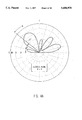
- FIG. 4A is a polar plot of an example of a radiation pattern, in elevation, of a phase array antenna in accordance with the teachings of this invention.
- FIG. 4B is representation of a rectangular and spherical coordinate system showing the antenna of the present invention at the origin and defining the angles ⁇ , and ⁇ used in the polar plots of FIGS. 4A and 5, relative to the rectangular coordinate system.
- the conical cut creates a surface representation of the antenna gain.
- FIG. 6 is block diagram of the antenna shown in FIG. 2, constructed in accordance with the teachings of this invention.
- FIGS. 7A and 7B are plan views of a printed circuit board pair used to construct the antenna shown schematically in FIG. 6.
- FIGS. 8A and 8B are plan views of the opposite sides of the printed circuit boards shown in FIGS. 7A and 7B.
- FIG. 9 is a sectional view of the assembled printed circuit board pair taken at the balun location.
- dipole antenna elements 14 each comprised of a pair of radiation elements 15 and 16, are supported by and fed by a pair of printed circuit boards 18 and 20.
- the antenna elements are arranged in an H plane array; i.e. the E planes of all elements are parallel and the H planes of all elements are coplanar.
- the radiation elements 15 and 16 are shown here as simple metal rods, but other dipole geometries may be used, such as the bent dipole geometry shown in the inset to FIG. 2.
- a metallic reflector 22 is disposed approximately 0.5 RF wavelengths from the dipole array (with the best spacing a function of the overall geometry). As will be explained more completely in connection with FIGS.
- the space 24 may be essentially void or may be filled with dielectric material appropriate to the electrical and mechanical design.
- the stripline terminology refers to a symmetrical pair of flat conductors forming a balanced configuration rather than the commonly used triplate (unbalanced) stripline configuration.
- the array axis 26 is along the line which connects the centers of all the array elements.
- FIG. 3 depicts the antenna shown in FIG. 2 installed between parallel sets of railroad tracks.
- the antenna includes a radome housing 27 for protection from weather and other things in the environment which would adversely effect the antenna operation.
- the radome cover can be fabricated of commonly available plastic, such as polycarbonate.
- the overall height of the antenna allows it to be placed on the ground below level of the top-of-rail.
- the array axis 26 is normal to the track path and the antenna beam is tilted, by phasing, toward the passing tags 10 as illustrated, with a beamwidth, in elevation, designed to illuminate as strongly as practical the range in elevation where the tag may be located (24" to 60" above rail).
- FIG. 4A shows an example of a desired pattern in elevation.
- FIG. 4B shows that angle ⁇ is measured from the z axis to the beam.
- the angle ⁇ is measured from the x axis to the projection of the beam in the x-y plane.
- the azimuth pattern of the antenna i.e. the pattern along the path of the passing railroad car tags
- the gain on either side of the principal lobe axis in azimuth 21 is relatively flat or is enhanced depending on zenith angle.
- the azimuth pattern characteristic is primarily a result of the shape of the dipole radiator elements 15 and 16 and the spacing of the dipole elements from the reflector 22.
- the polar plots of FIGS. 4A and 5 have concentric circles showing the absolute gain in decibels increasing in the radially outward direction.
- the bent dipole depicted in the inset of FIG. 2A contributes additional radiation at wide angles compared to a straight dipole. Also, the reflection (or the image) of the dipole element spaced 0.48 wavelengths from the reflector surface produces a net pattern with the useful shape of FIG. 5. Since the reflector is a primary contributor to the wide-angle pattern, its dimension W parallel to rails is large compared to conventional reflector-backed antennas; the width W of the antenna shown in FIG. 2 has a 2.8 wavelength-wide reflector compared to a one-wavelength (or less) reflector width for a common antenna. However, those skilled in the art will recognize this as a non-critical dimension. Narrower reflectors could alternatively be used without substantial change in performance.
- FIG. 6 is an electrical, block diagram of the antenna shown in FIG. 2.
- a balun 30, which is integrated onto the circuit boards 18 and 20, provides a conversion and impedance matching from an unbalanced coaxial input 32 to a stripline feed network comprised of a "tree" of balanced transmission lines of various characteristic impedances labeled ZoL, etc., and electrical lengths labeled dL, etc.
- the antenna element loads are shown as boxes with Z1, Z2, Z3 and Z4.
- the impedance Z and length d of each stripline branch of the tree is selected to excite the antenna elements with phase displaced currents I1, I2, I3 and I4 so that the array gives a desired pattern factor in elevation.
- the parameters Z and d which determine the element-to-element phase shift, can be determined by transmission-line circuit analysis, with due treatment of the mutual coupling of antenna elements.
- the distribution network parameters (Z, d) were adjusted to give a nominally uniform amplitude distribution with a progressive phase shift of 100 degrees per element in an array with an element-to-element spacing of 0.58 wavelengths. This simple design is not broadband, but has more than adequate bandwidth for many applications.
- FIGS. 7A and 7B show respectively the surfaces of the boards 18 and 20 that face one another when the boards are assembled.
- FIG. 7B is up-side-down with respect to FIG. 7A.
- Each board has four antenna element terminals 40 to which the elements 15 and 16 are respectively electrically and mechanically coupled.
- each board has a set of circuit traces 42 extending horizontally from a vertical circuit trace 44 that form components of the balun. It will be appreciated that when the boards 18 and 20 are assembled, the traces on their interior surfaces shown here match up with one another and form strip transmission lines for the RF power.
- the corresponding trace patterns while preferably on the interior surface of the boards, as shown, could alternatively be positioned on the exterior surfaces of the boards.
- Varying the width and board-to-board spacing of the circuit traces of the power distribution network varies the impedance of the resulting strip transmission lines from the balun to the dipole elements 15 and 16 and the combination of variations in impedance and length from one element to the next varies the relative phase of the excitation of the respective dipole elements.
- baluns i.e. unbalanced to balanced signal transformation devices
- the balun structure here, comprises, in addition to the vertical stripline transmission line formed by the traces 44 on each board, a shorting plate 46 on the interior surface of the board 18. Plate 46 shorts the vertical trace 44 on board 18 to a corresponding section of the vertical trace on board 20, so that the remaining (unshorted) parts of the vertical traces form a balanced quarter-wavelength stub in parallel with the balanced feed point near the feed hole.
- a central conductor 48 of a coaxial feed is connected to a circuit trace 50 on the outer surface of printed circuit board 18, and forms a microstrip transmission line with the vertical trace 44 on the interior surface of the board 18.
- This trace 50 which is a component of the balun, extends to a hole 52, through which extends a bridge wire 54, connecting the trace 50 to a circuit trace 56 on the outer surface of board 18.
- the bridge wire is insulated from the interior traces 44 on each board allowing only the direct electrical connection between the traces on the exterior surfaces of the boards. This topology, using an insulated through hole permits proper excitation of the interior traces 40, 42, and 44 by means of electromagnetic coupling.
- Circuit trace 56 which forms a microstrip transmission line with the vertical trace 46 on the inner side of the board, serves as an impedance matching and compensation stub in the balun.
- the outer conductor 58 of the coaxial feed is connected, via the reflector 22, to the shorting plate 42 and the circuit traces 50 on the outer surface of the printed circuit board 18.
Abstract
Description
Claims (7)
Priority Applications (2)
| Application Number | Priority Date | Filing Date | Title |
|---|---|---|---|
| US08/542,755 US5686928A (en) | 1995-10-13 | 1995-10-13 | Phased array antenna for radio frequency identification |
| US08/899,166 US6127981A (en) | 1995-10-13 | 1997-07-23 | Phased array antenna for radio frequency identification |
Applications Claiming Priority (1)
| Application Number | Priority Date | Filing Date | Title |
|---|---|---|---|
| US08/542,755 US5686928A (en) | 1995-10-13 | 1995-10-13 | Phased array antenna for radio frequency identification |
Related Child Applications (1)
| Application Number | Title | Priority Date | Filing Date |
|---|---|---|---|
| US08/899,166 Continuation US6127981A (en) | 1995-10-13 | 1997-07-23 | Phased array antenna for radio frequency identification |
Publications (1)
| Publication Number | Publication Date |
|---|---|
| US5686928A true US5686928A (en) | 1997-11-11 |
Family
ID=24165151
Family Applications (2)
| Application Number | Title | Priority Date | Filing Date |
|---|---|---|---|
| US08/542,755 Expired - Lifetime US5686928A (en) | 1995-10-13 | 1995-10-13 | Phased array antenna for radio frequency identification |
| US08/899,166 Expired - Lifetime US6127981A (en) | 1995-10-13 | 1997-07-23 | Phased array antenna for radio frequency identification |
Family Applications After (1)
| Application Number | Title | Priority Date | Filing Date |
|---|---|---|---|
| US08/899,166 Expired - Lifetime US6127981A (en) | 1995-10-13 | 1997-07-23 | Phased array antenna for radio frequency identification |
Country Status (1)
| Country | Link |
|---|---|
| US (2) | US5686928A (en) |
Cited By (37)
| Publication number | Priority date | Publication date | Assignee | Title |
|---|---|---|---|---|
| US6046683A (en) * | 1996-12-31 | 2000-04-04 | Lucent Technologies Inc. | Modulated backscatter location system |
| US6084530A (en) * | 1996-12-30 | 2000-07-04 | Lucent Technologies Inc. | Modulated backscatter sensor system |
| US6130623A (en) * | 1996-12-31 | 2000-10-10 | Lucent Technologies Inc. | Encryption for modulated backscatter systems |
| US6177872B1 (en) * | 1998-03-13 | 2001-01-23 | Intermec Ip Corp. | Distributed impedance matching circuit for high reflection coefficient load |
| US6184841B1 (en) * | 1996-12-31 | 2001-02-06 | Lucent Technologies Inc. | Antenna array in an RFID system |
| US6215402B1 (en) * | 1998-03-13 | 2001-04-10 | Intermec Ip Corp. | Radio frequency identification transponder employing patch antenna |
| US6239764B1 (en) | 1998-06-09 | 2001-05-29 | Samsung Electronics Co., Ltd. | Wideband microstrip dipole antenna array and method for forming such array |
| US6281794B1 (en) * | 1998-01-02 | 2001-08-28 | Intermec Ip Corp. | Radio frequency transponder with improved read distance |
| US6369710B1 (en) | 2000-03-27 | 2002-04-09 | Lucent Technologies Inc. | Wireless security system |
| US6396449B1 (en) | 2001-03-15 | 2002-05-28 | The Boeing Company | Layered electronically scanned antenna and method therefor |
| US6441740B1 (en) * | 1998-02-27 | 2002-08-27 | Intermec Ip Corp. | Radio frequency identification transponder having a reflector |
| US6456668B1 (en) | 1996-12-31 | 2002-09-24 | Lucent Technologies Inc. | QPSK modulated backscatter system |
| US6615026B1 (en) * | 1999-02-01 | 2003-09-02 | A. W. Technologies, Llc | Portable telephone with directional transmission antenna |
| US6661339B2 (en) | 2000-01-24 | 2003-12-09 | Nextreme, L.L.C. | High performance fuel tank |
| US20040201539A1 (en) * | 2003-04-09 | 2004-10-14 | Yewen Robert G. | Radio frequency identification system and antenna system |
| US20040263390A1 (en) * | 2003-06-26 | 2004-12-30 | Skypilot Network, Inc. | Planar antenna for a wireless mesh network |
| US20050197074A1 (en) * | 2004-02-12 | 2005-09-08 | Cullen James M. | RFID tag and method of manufacturing the same |
| US20060232422A1 (en) * | 2005-03-29 | 2006-10-19 | Zhong-Min Liu | RFID conveyor system |
| US20060273865A1 (en) * | 2005-06-02 | 2006-12-07 | Timofeev Igor E | Dipole antenna array |
| US20070132591A1 (en) * | 2005-12-08 | 2007-06-14 | Ncr Corporation | RFID device |
| US20100141530A1 (en) * | 2008-12-10 | 2010-06-10 | Sensis Corporation | Dipole array with reflector and integrated electronics |
| US7752980B2 (en) | 2000-01-24 | 2010-07-13 | Nextreme Llc | Material handling apparatus having a reader/writer |
| US20100219953A1 (en) * | 2009-02-27 | 2010-09-02 | Rf Controls, Llc | Radio Frequency Environment Object Monitoring System and Methods of Use |
| US20100225480A1 (en) * | 2007-09-11 | 2010-09-09 | Rf Controls, Llc | Radio frequency signal acquisition and source location system |
| US20100277319A1 (en) * | 2009-03-30 | 2010-11-04 | Goidas Peter J | Radio frequency identification tag identification system |
| US20110032079A1 (en) * | 2009-08-10 | 2011-02-10 | Rf Controls, Llc | Antenna switching arrangement |
| US20110063113A1 (en) * | 2009-09-10 | 2011-03-17 | Rf Controls, Llc | Calibration and Operational Assurance Method and Apparatus for RFID Object Monitoring System |
| US7948371B2 (en) | 2000-01-24 | 2011-05-24 | Nextreme Llc | Material handling apparatus with a cellular communications device |
| US8077040B2 (en) | 2000-01-24 | 2011-12-13 | Nextreme, Llc | RF-enabled pallet |
| US20150022413A1 (en) * | 2013-07-17 | 2015-01-22 | Thomson Licensing | Multi-sector directive antenna |
| US9227641B2 (en) | 2013-05-03 | 2016-01-05 | Thales Canada Inc | Vehicle position determining system and method of using the same |
| CN106374219A (en) * | 2016-09-20 | 2017-02-01 | 深圳市中天迅通信技术有限公司 | Non-frequency-offset copper bush antenna for POS machine |
| CN107546478A (en) * | 2017-07-25 | 2018-01-05 | 西安电子科技大学 | Using the large-angle scanning phased array antenna and design method of particular orientation figure array element |
| CN107611597A (en) * | 2017-07-25 | 2018-01-19 | 西安电子科技大学 | With shaped-beam and close coupling submatrix and design method can be cutd open as the low of array element |
| CN109346826A (en) * | 2018-09-12 | 2019-02-15 | 上海无线电设备研究所 | Multipolarization dipole antenna |
| US20190214713A1 (en) * | 2016-09-21 | 2019-07-11 | Hirschmann Car Communication Gmbh | Antenna device |
| US20230114757A1 (en) * | 2021-10-12 | 2023-04-13 | Qualcomm Incorporated | Multi-directional dual-polarized antenna system |
Families Citing this family (14)
| Publication number | Priority date | Publication date | Assignee | Title |
|---|---|---|---|---|
| USRE47599E1 (en) | 2000-10-20 | 2019-09-10 | Promega Corporation | RF point of sale and delivery method and system using communication with remote computer and having features to read a large number of RF tags |
| US20020183882A1 (en) | 2000-10-20 | 2002-12-05 | Michael Dearing | RF point of sale and delivery method and system using communication with remote computer and having features to read a large number of RF tags |
| WO2002035432A1 (en) | 2000-10-20 | 2002-05-02 | Promega Corporation | Radio frequency identification method and system of distributing products |
| US6429816B1 (en) * | 2001-05-04 | 2002-08-06 | Harris Corporation | Spatially orthogonal signal distribution and support architecture for multi-beam phased array antenna |
| GB2402920A (en) * | 2003-06-21 | 2004-12-22 | Arjo Med Aktiebolag Ltd | Sling attachment device |
| US7027005B1 (en) * | 2004-09-23 | 2006-04-11 | Smartant Telecom Co., Ltd. | Broadband dipole array antenna |
| US7873326B2 (en) | 2006-07-11 | 2011-01-18 | Mojix, Inc. | RFID beam forming system |
| US7710275B2 (en) | 2007-03-16 | 2010-05-04 | Promega Corporation | RFID reader enclosure and man-o-war RFID reader system |
| WO2009151778A2 (en) | 2008-04-14 | 2009-12-17 | Mojix, Inc. | Radio frequency identification tag location estimation and tracking system and method |
| US8461965B2 (en) * | 2010-01-13 | 2013-06-11 | The Boeing Company | Portable radio frequency identification (RFID) reader |
| US8929494B2 (en) | 2010-11-30 | 2015-01-06 | Mojix, Inc. | Systems and methods for joint beamforming and preamble detection |
| CN102280717B (en) * | 2011-04-26 | 2014-07-30 | 惠州Tcl移动通信有限公司 | Mobile terminal antenna and realization method thereof |
| IL223415A (en) * | 2012-12-04 | 2017-06-29 | Elta Systems Ltd | Rotatable transponder system |
| US9883337B2 (en) | 2015-04-24 | 2018-01-30 | Mijix, Inc. | Location based services for RFID and sensor networks |
Citations (14)
| Publication number | Priority date | Publication date | Assignee | Title |
|---|---|---|---|---|
| US3681769A (en) * | 1970-07-30 | 1972-08-01 | Itt | Dual polarized printed circuit dipole antenna array |
| US3750185A (en) * | 1972-01-18 | 1973-07-31 | Westinghouse Electric Corp | Dipole antenna array |
| US3845490A (en) * | 1973-05-03 | 1974-10-29 | Gen Electric | Stripline slotted balun dipole antenna |
| US4075632A (en) * | 1974-08-27 | 1978-02-21 | The United States Of America As Represented By The United States Department Of Energy | Interrogation, and detection system |
| US4287518A (en) * | 1980-04-30 | 1981-09-01 | Nasa | Cavity-backed, micro-strip dipole antenna array |
| JPS5862902A (en) * | 1981-10-09 | 1983-04-14 | Mitsubishi Electric Corp | Printed dipole antenna |
| US4460877A (en) * | 1982-11-22 | 1984-07-17 | International Telephone And Telegraph Corporation | Broad-band printed-circuit balun employing coupled-strip all pass filters |
| US4495505A (en) * | 1983-05-10 | 1985-01-22 | The United States Of America As Represented By The Secretary Of The Air Force | Printed circuit balun with a dipole antenna |
| US4739328A (en) * | 1986-07-14 | 1988-04-19 | Amtech Corporation | System for identifying particular objects |
| US4800393A (en) * | 1987-08-03 | 1989-01-24 | General Electric Company | Microstrip fed printed dipole with an integral balun and 180 degree phase shift bit |
| US4847626A (en) * | 1987-07-01 | 1989-07-11 | Motorola, Inc. | Microstrip balun-antenna |
| US5087922A (en) * | 1989-12-08 | 1992-02-11 | Hughes Aircraft Company | Multi-frequency band phased array antenna using coplanar dipole array with multiple feed ports |
| US5258770A (en) * | 1991-08-29 | 1993-11-02 | Mcdonnell Douglas Corporation | Ground independent feed network for a multiterminal antenna |
| US5440318A (en) * | 1990-08-22 | 1995-08-08 | Butland; Roger J. | Panel antenna having groups of dipoles fed with insertable delay lines for electrical beam tilting and a mechanically tiltable ground plane |
Family Cites Families (2)
| Publication number | Priority date | Publication date | Assignee | Title |
|---|---|---|---|---|
| JPS5910623B2 (en) * | 1976-11-16 | 1984-03-10 | 住友電気工業株式会社 | bus detection device |
| JPH0643900B2 (en) * | 1987-06-22 | 1994-06-08 | 住友電気工業株式会社 | Roadside beacon method |
-
1995
- 1995-10-13 US US08/542,755 patent/US5686928A/en not_active Expired - Lifetime
-
1997
- 1997-07-23 US US08/899,166 patent/US6127981A/en not_active Expired - Lifetime
Patent Citations (14)
| Publication number | Priority date | Publication date | Assignee | Title |
|---|---|---|---|---|
| US3681769A (en) * | 1970-07-30 | 1972-08-01 | Itt | Dual polarized printed circuit dipole antenna array |
| US3750185A (en) * | 1972-01-18 | 1973-07-31 | Westinghouse Electric Corp | Dipole antenna array |
| US3845490A (en) * | 1973-05-03 | 1974-10-29 | Gen Electric | Stripline slotted balun dipole antenna |
| US4075632A (en) * | 1974-08-27 | 1978-02-21 | The United States Of America As Represented By The United States Department Of Energy | Interrogation, and detection system |
| US4287518A (en) * | 1980-04-30 | 1981-09-01 | Nasa | Cavity-backed, micro-strip dipole antenna array |
| JPS5862902A (en) * | 1981-10-09 | 1983-04-14 | Mitsubishi Electric Corp | Printed dipole antenna |
| US4460877A (en) * | 1982-11-22 | 1984-07-17 | International Telephone And Telegraph Corporation | Broad-band printed-circuit balun employing coupled-strip all pass filters |
| US4495505A (en) * | 1983-05-10 | 1985-01-22 | The United States Of America As Represented By The Secretary Of The Air Force | Printed circuit balun with a dipole antenna |
| US4739328A (en) * | 1986-07-14 | 1988-04-19 | Amtech Corporation | System for identifying particular objects |
| US4847626A (en) * | 1987-07-01 | 1989-07-11 | Motorola, Inc. | Microstrip balun-antenna |
| US4800393A (en) * | 1987-08-03 | 1989-01-24 | General Electric Company | Microstrip fed printed dipole with an integral balun and 180 degree phase shift bit |
| US5087922A (en) * | 1989-12-08 | 1992-02-11 | Hughes Aircraft Company | Multi-frequency band phased array antenna using coplanar dipole array with multiple feed ports |
| US5440318A (en) * | 1990-08-22 | 1995-08-08 | Butland; Roger J. | Panel antenna having groups of dipoles fed with insertable delay lines for electrical beam tilting and a mechanically tiltable ground plane |
| US5258770A (en) * | 1991-08-29 | 1993-11-02 | Mcdonnell Douglas Corporation | Ground independent feed network for a multiterminal antenna |
Non-Patent Citations (2)
| Title |
|---|
| IBM Technical Disclosure Bulletin, vol. 37, No. 06A, Jun. 1994, pp. 145 146. * |
| IBM Technical Disclosure Bulletin, vol. 37, No. 06A, Jun. 1994, pp. 145-146. |
Cited By (67)
| Publication number | Priority date | Publication date | Assignee | Title |
|---|---|---|---|---|
| US6084530A (en) * | 1996-12-30 | 2000-07-04 | Lucent Technologies Inc. | Modulated backscatter sensor system |
| US6130623A (en) * | 1996-12-31 | 2000-10-10 | Lucent Technologies Inc. | Encryption for modulated backscatter systems |
| US6046683A (en) * | 1996-12-31 | 2000-04-04 | Lucent Technologies Inc. | Modulated backscatter location system |
| US6184841B1 (en) * | 1996-12-31 | 2001-02-06 | Lucent Technologies Inc. | Antenna array in an RFID system |
| US6456668B1 (en) | 1996-12-31 | 2002-09-24 | Lucent Technologies Inc. | QPSK modulated backscatter system |
| US6281794B1 (en) * | 1998-01-02 | 2001-08-28 | Intermec Ip Corp. | Radio frequency transponder with improved read distance |
| US6441740B1 (en) * | 1998-02-27 | 2002-08-27 | Intermec Ip Corp. | Radio frequency identification transponder having a reflector |
| US6215402B1 (en) * | 1998-03-13 | 2001-04-10 | Intermec Ip Corp. | Radio frequency identification transponder employing patch antenna |
| US6177872B1 (en) * | 1998-03-13 | 2001-01-23 | Intermec Ip Corp. | Distributed impedance matching circuit for high reflection coefficient load |
| US6239764B1 (en) | 1998-06-09 | 2001-05-29 | Samsung Electronics Co., Ltd. | Wideband microstrip dipole antenna array and method for forming such array |
| US6615026B1 (en) * | 1999-02-01 | 2003-09-02 | A. W. Technologies, Llc | Portable telephone with directional transmission antenna |
| US7948371B2 (en) | 2000-01-24 | 2011-05-24 | Nextreme Llc | Material handling apparatus with a cellular communications device |
| US7752980B2 (en) | 2000-01-24 | 2010-07-13 | Nextreme Llc | Material handling apparatus having a reader/writer |
| US6661339B2 (en) | 2000-01-24 | 2003-12-09 | Nextreme, L.L.C. | High performance fuel tank |
| US9230227B2 (en) | 2000-01-24 | 2016-01-05 | Nextreme, Llc | Pallet |
| US7804400B2 (en) | 2000-01-24 | 2010-09-28 | Nextreme, Llc | Thermoformed platform having a communications device |
| US8585850B2 (en) | 2000-01-24 | 2013-11-19 | Nextreme, Llc | Thermoformed platform having a communications device |
| US8077040B2 (en) | 2000-01-24 | 2011-12-13 | Nextreme, Llc | RF-enabled pallet |
| US6369710B1 (en) | 2000-03-27 | 2002-04-09 | Lucent Technologies Inc. | Wireless security system |
| US6396449B1 (en) | 2001-03-15 | 2002-05-28 | The Boeing Company | Layered electronically scanned antenna and method therefor |
| US20040201539A1 (en) * | 2003-04-09 | 2004-10-14 | Yewen Robert G. | Radio frequency identification system and antenna system |
| US7053853B2 (en) | 2003-06-26 | 2006-05-30 | Skypilot Network, Inc. | Planar antenna for a wireless mesh network |
| US20040263390A1 (en) * | 2003-06-26 | 2004-12-30 | Skypilot Network, Inc. | Planar antenna for a wireless mesh network |
| US7755484B2 (en) | 2004-02-12 | 2010-07-13 | Avery Dennison Corporation | RFID tag and method of manufacturing the same |
| US20050197074A1 (en) * | 2004-02-12 | 2005-09-08 | Cullen James M. | RFID tag and method of manufacturing the same |
| US7576655B2 (en) | 2005-03-29 | 2009-08-18 | Accu-Sort Systems, Inc. | RFID conveyor system and method |
| US20060244609A1 (en) * | 2005-03-29 | 2006-11-02 | Zhong-Min Liu | RFID conveyor system |
| US7592915B2 (en) | 2005-03-29 | 2009-09-22 | Accu-Sort Systems, Inc. | RFID conveyor system |
| US7538675B2 (en) | 2005-03-29 | 2009-05-26 | Accu-Sort Systems, Inc. | RFID conveyor system |
| US20060232422A1 (en) * | 2005-03-29 | 2006-10-19 | Zhong-Min Liu | RFID conveyor system |
| US7518513B2 (en) | 2005-03-29 | 2009-04-14 | Accu-Sort Systems, Inc. | RFID conveyor system |
| US20060250253A1 (en) * | 2005-03-29 | 2006-11-09 | Zhong-Min Liu | RFID conveyor system and method |
| US20060238351A1 (en) * | 2005-03-29 | 2006-10-26 | Hillegass Raymond R | RFID conveyor system |
| US7639198B2 (en) * | 2005-06-02 | 2009-12-29 | Andrew Llc | Dipole antenna array having dipole arms tilted at an acute angle |
| US20060273865A1 (en) * | 2005-06-02 | 2006-12-07 | Timofeev Igor E | Dipole antenna array |
| US7573388B2 (en) * | 2005-12-08 | 2009-08-11 | The Kennedy Group, Inc. | RFID device with augmented grain |
| US20070132591A1 (en) * | 2005-12-08 | 2007-06-14 | Ncr Corporation | RFID device |
| US8421631B2 (en) | 2007-09-11 | 2013-04-16 | Rf Controls, Llc | Radio frequency signal acquisition and source location system |
| US20100225480A1 (en) * | 2007-09-11 | 2010-09-09 | Rf Controls, Llc | Radio frequency signal acquisition and source location system |
| US8742896B2 (en) | 2007-09-11 | 2014-06-03 | Rf Controls, Llc | Steerable phase array antenna RFID tag locater and tracking system and methods |
| US8659430B2 (en) | 2007-09-11 | 2014-02-25 | Rf Controls, Llc | Radio frequency signal acquisition and source location system |
| US8138986B2 (en) | 2008-12-10 | 2012-03-20 | Sensis Corporation | Dipole array with reflector and integrated electronics |
| US20100141530A1 (en) * | 2008-12-10 | 2010-06-10 | Sensis Corporation | Dipole array with reflector and integrated electronics |
| US20100219953A1 (en) * | 2009-02-27 | 2010-09-02 | Rf Controls, Llc | Radio Frequency Environment Object Monitoring System and Methods of Use |
| US8120488B2 (en) | 2009-02-27 | 2012-02-21 | Rf Controls, Llc | Radio frequency environment object monitoring system and methods of use |
| US8599024B2 (en) | 2009-02-27 | 2013-12-03 | Rf Controls, Llc | Radio frequency environment object monitoring system and methods of use |
| US8854212B2 (en) | 2009-03-30 | 2014-10-07 | Datalogic Automation, Inc. | Radio frequency identification tag identification system |
| US20100277319A1 (en) * | 2009-03-30 | 2010-11-04 | Goidas Peter J | Radio frequency identification tag identification system |
| US10262173B2 (en) | 2009-03-30 | 2019-04-16 | Datalogic Usa, Inc. | Radio frequency identification tag identification system |
| US9262657B2 (en) | 2009-03-30 | 2016-02-16 | Datalogic Automation, Inc. | Radio frequency identification tag identification system |
| US8698575B2 (en) | 2009-08-10 | 2014-04-15 | Rf Controls, Llc | Antenna switching arrangement |
| US20110032079A1 (en) * | 2009-08-10 | 2011-02-10 | Rf Controls, Llc | Antenna switching arrangement |
| US8344823B2 (en) | 2009-08-10 | 2013-01-01 | Rf Controls, Llc | Antenna switching arrangement |
| US8451121B2 (en) | 2009-09-10 | 2013-05-28 | PF Controls, LLC | Calibration and operational assurance method and apparatus for RFID object monitoring system |
| US20110063113A1 (en) * | 2009-09-10 | 2011-03-17 | Rf Controls, Llc | Calibration and Operational Assurance Method and Apparatus for RFID Object Monitoring System |
| US9227641B2 (en) | 2013-05-03 | 2016-01-05 | Thales Canada Inc | Vehicle position determining system and method of using the same |
| US9499184B2 (en) | 2013-05-03 | 2016-11-22 | Thales Canada Inc | Method of determining a position of a vehicle on a guideway |
| US20150022413A1 (en) * | 2013-07-17 | 2015-01-22 | Thomson Licensing | Multi-sector directive antenna |
| US9912080B2 (en) * | 2013-07-17 | 2018-03-06 | Thomson Licensing | Multi-sector directive antenna |
| CN106374219A (en) * | 2016-09-20 | 2017-02-01 | 深圳市中天迅通信技术有限公司 | Non-frequency-offset copper bush antenna for POS machine |
| US20190214713A1 (en) * | 2016-09-21 | 2019-07-11 | Hirschmann Car Communication Gmbh | Antenna device |
| US10559876B2 (en) * | 2016-09-21 | 2020-02-11 | Hirschmann Car Communication Gmbh | Antenna device |
| CN107546478A (en) * | 2017-07-25 | 2018-01-05 | 西安电子科技大学 | Using the large-angle scanning phased array antenna and design method of particular orientation figure array element |
| CN107611597A (en) * | 2017-07-25 | 2018-01-19 | 西安电子科技大学 | With shaped-beam and close coupling submatrix and design method can be cutd open as the low of array element |
| CN109346826A (en) * | 2018-09-12 | 2019-02-15 | 上海无线电设备研究所 | Multipolarization dipole antenna |
| US20230114757A1 (en) * | 2021-10-12 | 2023-04-13 | Qualcomm Incorporated | Multi-directional dual-polarized antenna system |
| US11784418B2 (en) * | 2021-10-12 | 2023-10-10 | Qualcomm Incorporated | Multi-directional dual-polarized antenna system |
Also Published As
| Publication number | Publication date |
|---|---|
| US6127981A (en) | 2000-10-03 |
Similar Documents
| Publication | Publication Date | Title |
|---|---|---|
| US5686928A (en) | Phased array antenna for radio frequency identification | |
| EP1590857B1 (en) | Low profile dual frequency dipole antenna structure | |
| JP3093715B2 (en) | Microstrip dipole antenna array with resonator attachment | |
| US4724443A (en) | Patch antenna with a strip line feed element | |
| US6424311B1 (en) | Dual-fed coupled stripline PCB dipole antenna | |
| US6008764A (en) | Broadband antenna realized with shorted microstrips | |
| EP1263085B1 (en) | Omnidirectional antenna | |
| US4916457A (en) | Printed-circuit crossed-slot antenna | |
| US4899164A (en) | Slot coupled microstrip constrained lens | |
| US6970134B2 (en) | Broadband antenna apparatus | |
| US5212494A (en) | Compact multi-polarized broadband antenna | |
| US11095040B2 (en) | Antenna and mimo antenna | |
| US5444452A (en) | Dual frequency antenna | |
| US20070013599A1 (en) | Apparatus and methods for constructing and packaging printed antenna devices | |
| CN112635988B (en) | Antenna element unit | |
| US20030112200A1 (en) | Horizontally polarized printed circuit antenna array | |
| US7375697B2 (en) | Meandered slit antenna | |
| JPH03213005A (en) | Forced excitation array antenna | |
| CN210111048U (en) | Microstrip array antenna | |
| WO2001028111A1 (en) | Wide beamwidth antenna | |
| CN111684656A (en) | Antenna for communication with a transponder | |
| KR20230048359A (en) | antenna array | |
| US20200136272A1 (en) | Dual-polarized Wide-Bandwidth Antenna | |
| US10862220B2 (en) | Antenna for use in electronic communication systems | |
| JPS60803B2 (en) | antenna device |
Legal Events
| Date | Code | Title | Description |
|---|---|---|---|
| AS | Assignment |
Owner name: LORAL FEDERAL SYSTEMS COMPANY, CALIFORNIA Free format text: ASSIGNMENT OF ASSIGNORS INTEREST;ASSIGNORS:PRITCHETT, DONALD MICHAEL;MILICIC, MATTHEW J., JR.;GREENE, EDWARD E.;REEL/FRAME:007784/0685 Effective date: 19960102 |
|
| STCF | Information on status: patent grant |
Free format text: PATENTED CASE |
|
| AS | Assignment |
Owner name: LOCKHEED MARTIN FEDERAL SYSTEMS, INC., MARYLAND Free format text: CHANGE OF NAME;ASSIGNOR:LORAL FEDERAL SYSTEMS COMPANY;REEL/FRAME:009586/0397 Effective date: 19960429 |
|
| AS | Assignment |
Owner name: LOCKHEED MARTIN CORP., MARYLAND Free format text: MERGER;ASSIGNOR:LOCKHEED MARTIN FEDERAL SYSTEMS, INC.;REEL/FRAME:010848/0560 Effective date: 19980617 |
|
| FEPP | Fee payment procedure |
Free format text: PAYOR NUMBER ASSIGNED (ORIGINAL EVENT CODE: ASPN); ENTITY STATUS OF PATENT OWNER: LARGE ENTITY |
|
| REFU | Refund |
Free format text: REFUND - SURCHARGE FOR LATE PAYMENT, LARGE ENTITY (ORIGINAL EVENT CODE: R186); ENTITY STATUS OF PATENT OWNER: LARGE ENTITY |
|
| FPAY | Fee payment |
Year of fee payment: 4 |
|
| FPAY | Fee payment |
Year of fee payment: 8 |
|
| FPAY | Fee payment |
Year of fee payment: 12 |