US5682098A - Open quadrature whole volume imaging NMR surface coil array including three figure-8 shaped surface coils - Google Patents
Open quadrature whole volume imaging NMR surface coil array including three figure-8 shaped surface coils Download PDFInfo
- Publication number
- US5682098A US5682098A US08/584,847 US58484796A US5682098A US 5682098 A US5682098 A US 5682098A US 58484796 A US58484796 A US 58484796A US 5682098 A US5682098 A US 5682098A
- Authority
- US
- United States
- Prior art keywords
- coil
- shaped
- coils
- quadrature
- shaped antenna
- Prior art date
- Legal status (The legal status is an assumption and is not a legal conclusion. Google has not performed a legal analysis and makes no representation as to the accuracy of the status listed.)
- Expired - Lifetime
Links
Images


Classifications
-
- G—PHYSICS
- G01—MEASURING; TESTING
- G01R—MEASURING ELECTRIC VARIABLES; MEASURING MAGNETIC VARIABLES
- G01R33/00—Arrangements or instruments for measuring magnetic variables
- G01R33/20—Arrangements or instruments for measuring magnetic variables involving magnetic resonance
- G01R33/28—Details of apparatus provided for in groups G01R33/44 - G01R33/64
- G01R33/32—Excitation or detection systems, e.g. using radio frequency signals
- G01R33/34—Constructional details, e.g. resonators, specially adapted to MR
- G01R33/341—Constructional details, e.g. resonators, specially adapted to MR comprising surface coils
- G01R33/3415—Constructional details, e.g. resonators, specially adapted to MR comprising surface coils comprising arrays of sub-coils, i.e. phased-array coils with flexible receiver channels
-
- G—PHYSICS
- G01—MEASURING; TESTING
- G01R—MEASURING ELECTRIC VARIABLES; MEASURING MAGNETIC VARIABLES
- G01R33/00—Arrangements or instruments for measuring magnetic variables
- G01R33/20—Arrangements or instruments for measuring magnetic variables involving magnetic resonance
- G01R33/28—Details of apparatus provided for in groups G01R33/44 - G01R33/64
- G01R33/32—Excitation or detection systems, e.g. using radio frequency signals
- G01R33/34—Constructional details, e.g. resonators, specially adapted to MR
- G01R33/34046—Volume type coils, e.g. bird-cage coils; Quadrature bird-cage coils; Circularly polarised coils
Definitions
- This invention generally relates to the field of magnetic resonance imaging (MRI), also known as nuclear magnetic resonance (NMR) imaging. More particularly, the present invention relates to an open, whole volume, general purpose, quadrature radio frequency (RF) surface coil array comprised entirely of figure eight shaped coils for magnetic resonance imaging.
- MRI magnetic resonance imaging
- NMR nuclear magnetic resonance
- RF radio frequency
- a conventional MRI imaging system is comprised of at least in part a super conducting magnet that generates a static, highly homogenous magnetic field B o ; a gradient coil system that generates gradient fields G x , G y , and G z in the X, Y, and Z directions; a body coil that generates polarized RF excitations and that also detects RF signals; and a signal detection and image reconstruction system that generates suitable images of an object to be viewed.
- NMR nuclear magnetic resonance
- ⁇ is the gyromagnetic constant which has a different value for different nuclei
- ⁇ is the Larmor frequency
- a body coil is used to generate a plane polarized magnetic field in a plane perpendicular to the static magnetic field B o .
- Such a field couples to the nuclei and excites them.
- the gradient coil system is used at the same time to modulate the static magnetic field B o such that a unique Larmor frequency is provided at different points in space.
- the nuclear spins relax back to the original state and in doing so, they generate signals at the Larmor frequency. These signals are then detected by the body coil and fed to the image reconstruction system.
- SNR Signal-to-noise ratio
- the simplest surface coils are single loop coils of different diameters. Although such coils produce a high SNR, they also produce a very nonhomogenous field, which rapidly drops off as the distance between the loop and the volume being imaged increases. Accordingly, these single loop type surface coils are unsuitable for whole volume imaging. If two such coils are tuned to a frequency F 0 and brought close to each other in order to improve the homogeneity, there is a split in frequency response, reduction in sensitivity and a decrease in SNR.
- Saddle coils generally consisting of two oppositely disposed loops which enclose the volume being imaged, have been used to overcome the homogeneity shortcomings of the single loop coils.
- the splitting of frequency response of the two loops is overcome by connecting the coils in series with a crossover such that the direction of current is always the same in the two loops.
- FIG. 1a illustrates the flux lines generated by single loop coils and saddle coils.
- Improvement in SNR performance also can be achieved by orienting two coils at 90° angles about the imaged object so that each detects RF energy along one of a pair of mutually perpendicular axes.
- This technique is generally known as quadrature detection, and the signals collected are termed quadrature signals.
- quadrature signals are summed together, using hybrid combiners, which phase shift one channel by 90° with respect to the other, and then add the signals.
- the uncorrelated noise from the two channels does not add up like the signals. Instead, the uncorrelated noise from the two channels adds up to ⁇ 2 times the value of the noise in one channel. Therefore, the SNR of the added signals is: ##EQU1## or, in other words, a 40% improvement over the SNR of a single channel, which is S/N.
- quadrature coil and quadrature signal will refer to the detecting of the NMR signal along perpendicular axes, and combining the signals so collected, with the appropriate phase shifts, to produce a signal of improved signal-to-noise ratio.
- FIG. 2a shows a conductor geometry that generates quadrature fields.
- the simple loop generates the vertical field, while the figure eight shaped coil generates the horizontal fields.
- the horizontal fields rapidly die down as the distance, in a vertical direction, from the figure eight shaped coil is increased. Therefore, the quadrature gain area is very close to the coils. Accordingly, such an arrangement is not suitable for imaging over a large volume.
- Such coils are mainly employed for imaging planar anatomy that is very close to the coils, e.g. a spine.
- FIG. 2b illustrates a coil pair which does not produce orthogonal fields, however, the individual coils are electrically well isolated.
- the direction of the flux lines in the overlap area is opposite to the direction of the flux lines in the nonoverlapped area. Isolation is achieved by overlapping the two coils such that the total flux coupling to a coil due to current flowing in the paired coil is zero.
- a bird cage coil When a bird cage coil is employed as a local coil, such as the coil disclosed in U.S. Pat. No. 5,370,118, the diameter of the loops and the length of the segments are reduced, so that the volume within the bird cage conforms closely to the imaged part.
- the bird cage structure For the imaging of human limbs, and particularly for the imaging of the knee, the bird cage structure is dimensioned so that its cylindrical volume conforms closely to the outer surface of the leg.
- the smallest practical radius of the bird cage is rarely realized for the reason that it is desired that the coil be suitable for imaging other members besides the knee, such as the foot.
- Imaging of the foot is preferably done with the foot in the anatomical position essentially perpendicular to the axis of the leg. The radial extension of the toes in this position limits how small the radius of the loops of the bird cage coil may be.
- the signal-to-noise ratio for bird cage coils intended for multipurpose imaging is significantly less than may be obtained for a coil not used for imaging the foot.
- a "bird cage” type coil is limited to cylindrical body parts that will fit inside the coil, e.g., a head or extremities. It is not possible to realize such a design for imaging odd shaped anatomy such as the shoulder. For such applications, a design that is open on one side such that the anatomy can be easily placed inside the coil is highly desirable.
- quadrature coil designs may operate with varying degrees of success, the opposing single loops of such quadrature coils couple strongly to each other and are not electrically isolated from each other. Accordingly, the quadrature gain of these coils is significantly reduced and costly preamplifiers must be employed to reduce the effects of mutual inductance.
- a general purpose quadrature whole volume NMR coil array for obtaining an NMR signal from precessing nuclei within an imaging volume.
- the coil array comprises at least three figure eight shaped antenna coils. Each figure eight shaped antenna coil is electrically isolated from each other figure eight shaped antenna coil.
- the figure eight shaped antenna coils are arranged such that quadrature fields are generated by the antenna coils, and a region of quadrature gain is created within a predetermined volume between the figure eight shaped coils.
- the NMR coil array is open and is configured to selectively wrap about an object to be imaged
- FIG. 1a illustrates the flux lines generated by a prior art single loop coil
- FIG. 1b illustrates the flux lines generated by a prior art saddle coil
- FIG. 2a illustrates the quadrature flux lines generated by a prior art loop and butterfly coil
- FIG. 2b illustrates the flux lines of a prior art coil pair
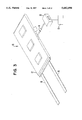
- FIG. 3 is an environmental view of one embodiment of the apparatus of the present invention.
- FIG. 4a illustrates the apparatus of FIG. 3 arranged for wrist imaging
- FIG. 4b illustrates the apparatus of FIG. 3 arranged for ankle imaging
- FIG. 4c illustrates the apparatus of FIG. 3 arranged for orbit imaging
- FIG. 5a illustrates a cutaway view of an antenna housing of the present invention revealing an antenna geometry on a flexible circuit
- FIG. 5b illustrates a wire line description of the antenna geometry of FIG. 5a
- FIG. 5c illustrates the flux generated in the X-Y plane by the antenna geometry of FIG. 5a
- FIG. 6 illustrates an alternate antenna configuration of the present invention
- FIG. 7 illustrates an alternate antenna configuration of the present invention.
- FIG. 8 illustrates a detailed electrical schematic of one embodiment of the present invention.
- the open quadrature whole volume imaging NMR surface coil array of the present invention is generally illustrated at 10 in the Figures.
- the coil 10 includes a flexible antenna package 12, which is electrically connected to an MRI scanner (schematically represented at 13) by way of a cable assembly 14, and an interconnect device 16.
- the flexible antenna package 12 houses the novel NMR coil array 10 of the present invention.
- the flexible antenna package 12 is fabricated from a suitable non-magnetic, non-conductive, low dielectric loss material, such as polymeric foam or fabric materials, or any other suitable materials.
- the cable assembly 14 may be comprised of a plurality of 50 ohm coaxial cables disposed in a soft, non-magnetic, non-conductive, low dielectric loss jacket material. In the illustrated embodiment of FIG. 8, three 50 ohm coaxial cables are provided. Each coaxial cable is electrically connected to an individual coil of the open quadrature whole volume imaging NMR coil array 10.
- the interconnect device 16 establishes electrical connection between the NMR coil array 10 and the MRI scanner 13.
- the interconnect device may include combiner electronics for adding channels, phase shifters for multichannel acquisitions, or coil identity electronics which permit the MRI scanner to recognize the NMR coil 10, and automatically load an appropriate software configuration.
- the flexible antenna package 12 may include a plurality of straps 18 for attachment to an object to be imaged.
- the straps 18 may include suitable fastener assemblies, such as but not limited to hook and pile type fasteners.
- FIGS. 4a, 4b and 4c generally illustrate the flexible antenna package 12 suitably attached to objects to be imaged. For example, in FIG. 4a the flexible antenna package 12 is attached to a patient's wrist; in FIG. 4b the flexible antenna package 12 is attached to a patient's ankle; and in FIG. 4c the flexible antenna package 12 is attached to a patient's head.
- FIG. 5a illustrates a cutaway view of the flexible antenna package 12 to reveal the internal components thereof.
- a flexible printed circuit board (PCB) 20 Internally disposed within the flexible antenna package 12 is a flexible printed circuit board (PCB) 20, which has etched thereon antenna traces in accordance with the teachings of the present invention.
- PCB printed circuit board
- the flexible antenna package 12 of the present invention is comprised entirely of figure eight shaped coils which are each electrically isolated from each other thereby eliminating the need for preamplifiers to minimize interactions between the coils. Two small figure eight shaped coils are illustrated at 32 and 34. A large figure eight shaped coil is illustrated at 36.
- Rigid printed circuit boards are provided on the flexible printed circuit board 20 at 22, 24 and 26.
- Rigid PCBs 22, 24 and 26 are electrically interconnected by way of 50 ⁇ coaxial cables 30.
- Cable assembly 14 is electrically connected to rigid PCB 24 by way of a nonmagnetic connector.
- a suitable nonmagnetic connector may be obtained from E. F. Johnson Connectors, Part No. 142-0407.014.
- FIG. 5b illustrates a three dimensional wire diagram of the flexible antenna package 12 of FIG. 5a.
- the three dimensional wire diagram comprises two small figure eight shaped quadrature coils 32 and 34 which are oppositely disposed to each other.
- a large figure eight shaped quadrature coil is provided at 36.
- the large figure eight shaped coil is disposed such that each half thereof is arranged in an opposite facing orientation.
- Each of the small figure eight shaped quadrature coils 32 and 34 are disposed within a respective half of the large figure eight shaped quadrature coil 36.
- FIG. 5c is a diagram showing quadrature detection of the three figure eight shaped coils in a region of interest between the figure eight shaped coils.
- flux line 40 is generated by the small figure eight shaped quadrature coil 32 and flux line 42 is generated by the small figure eight shaped quadrature coil 34.
- Solid flux lines 46 are generated by the large figure eight shaped quadrature coil 36.
- a region of quadrature gain is illustrated generally at 47.
- the flux lines 40 and 42 generated by the small figure eight shaped quadrature coils 32 and 34 are perpendicular to flux lines 46 generated by the large figure eight shaped coil 36. Therefore, the area of quadrature gain is defined generally at 47.
- the flux lines 40 and 42 weaken as the distance from the respective figure eight shaped quadrature coils 32 and 34 increases.
- the distance ⁇ D ⁇ which is located between the two opposing halves of the large figure eight shaped coil 36 determines the shape of the quadrature gain area. As the distance ⁇ D ⁇ decreases, the shape of the quadrature gain area changes from an hour glass shape to a more rectangular shape.
- FIG. 6 illustrates an alternate antenna embodiment comprising four figure eight shaped quadrature coils 48, 50, 52, and 54.
- quadrature coils 48 and 52 are electrically isolated from each other by using an overlapping technique.
- the static magnetic field B o produced by these quadrature coils is represented by the arrows.
- the length of the arrows is proportional to the magnitude of the field B o at that point, while the direction of the arrow is the same as that of the field.
- the geometry of the embodiment of FIG. 6 offers the advantage of a higher SNR as compared with the embodiment illustrated in FIGS. 5a-5c.
- FIG. 6 comprises two large figure eight shaped quadrature coils covering the same volume to be imaged, instead of the one quadrature coil of the embodiment of FIGS. 5a-5c. Accordingly, the size of the figure eight shaped quadrature coils of FIG. 6 are smaller than the quadrature coils of FIGS. 5a-5c thereby providing a higher SNR.
- FIG. 7 illustrates yet another alternate embodiment of the open, whole volume, general purpose, quadrature radio frequency (RF) surface coil array 10 of the present invention.
- the embodiment of FIG. 7 comprises six figure eight shaped quadrature coils 56, 58, 60, 62, 64, and 66.
- the embodiment of FIG. 7 will provide an even higher SNR than the embodiments of FIGS. 5a-5c and FIG. 6.
- FIG. 8 illustrates a detailed electrical schematic of one embodiment of the present invention.
- the detailed electrical schematic is generally representative of all embodiments of the present invention, except that the below described components of the electrical schematic will be suitably multiplied as individual antennas are added to alternate embodiments.
- the quadrature coils 32, 34 and 36 are disposed on the flexible PCB 20.
- Rigid PCBs 22, 24 and 26 are suitably attached to the flexible PCB 20, such as by rivets, for example.
- Each rigid PCB has a blocking circuit 68 which comprises a PIN type diode and an inductor tuned to a blocking capacitor.
- the PIN type diode is turned on by positive DC bias originating from the MRI scanner (not shown). Once the PIN diode is on, it open circuits a respective antenna coil. This is done automatically by the MRI scanner hardware when the body coil (not shown) is transmitting.
- Illustrated at 72 in each rigid PCB is an RF choke that permits a direct current through. Also, the RF choke 72 blocks any RF from passing through the choke.
- the matching capacitor 70 matches a respective antenna coil to 50 ohms when the antenna coil is employed on an average patient.
- Each quadrature antenna 32, 34 and 36 is electrically connected to the cable assembly 14.
- the cable 14 may be terminated by at least two methods. More particularly, if the NMR coil array 10 is used for phased array operation, the interconnect device 16 comprises three phase shifters 74 which transform preamplifier impedance such that at the matching capacitor 70, an inductor is formed. In a receive mode, this inductor resonates with a matching capacitor or tuning capacitor to block the flow of current in a quadrature coil.
- the interconnect device comprises a zero degree combiner 78 for adding the two small figure eight coils 32 and 34, first, and then a 90 degree hybrid combiner 76 for adding the signals from coil 36 to the sum of 32 and 34.
- An additional DC bias splitting circuit 80 is provided for splitting the DC bias current for each of the three blocking networks.
Abstract
Description
ω=γ.B.sub.o ;
Claims (8)
Priority Applications (1)
| Application Number | Priority Date | Filing Date | Title |
|---|---|---|---|
| US08/584,847 US5682098A (en) | 1996-01-11 | 1996-01-11 | Open quadrature whole volume imaging NMR surface coil array including three figure-8 shaped surface coils |
Applications Claiming Priority (1)
| Application Number | Priority Date | Filing Date | Title |
|---|---|---|---|
| US08/584,847 US5682098A (en) | 1996-01-11 | 1996-01-11 | Open quadrature whole volume imaging NMR surface coil array including three figure-8 shaped surface coils |
Publications (1)
| Publication Number | Publication Date |
|---|---|
| US5682098A true US5682098A (en) | 1997-10-28 |
Family
ID=24339029
Family Applications (1)
| Application Number | Title | Priority Date | Filing Date |
|---|---|---|---|
| US08/584,847 Expired - Lifetime US5682098A (en) | 1996-01-11 | 1996-01-11 | Open quadrature whole volume imaging NMR surface coil array including three figure-8 shaped surface coils |
Country Status (1)
| Country | Link |
|---|---|
| US (1) | US5682098A (en) |
Cited By (61)
| Publication number | Priority date | Publication date | Assignee | Title |
|---|---|---|---|---|
| US6114854A (en) * | 1997-05-26 | 2000-09-05 | Siemens Aktiengesellschaft | Antenna for a magnetic resonance device |
| US6144203A (en) * | 1997-11-28 | 2000-11-07 | Hitachi Medical Corporation | Coil harness assembly for interventional MRI application |
| EP1126285A1 (en) * | 2000-02-09 | 2001-08-22 | Ge Yokogawa Medical Systems, Ltd. | Phased array MRI RF coils |
| US6437567B1 (en) * | 1999-12-06 | 2002-08-20 | General Electric Company | Radio frequency coil for open magnetic resonance imaging system |
| US6438402B1 (en) * | 1997-11-20 | 2002-08-20 | Igc-Medical Advances, Inc. | Step-tapered flexible peripheral coil |
| US6498489B1 (en) | 2001-05-04 | 2002-12-24 | Kamal Vij | Magnetic resonance imaging coil arrays with separable imaging coil elements |
| US20020198450A1 (en) * | 2001-05-30 | 2002-12-26 | Siemens Aktiengesellschaft | High-frequency coil arrangement for a magnetic resonance tomography apparatus |
| US20030094948A1 (en) * | 2001-11-22 | 2003-05-22 | Kazuya Okamoto | RF coil and magnetic resonance imaging apparatus |
| US20030184294A1 (en) * | 2002-04-01 | 2003-10-02 | Boskamp Eddy Benjamin | Multiple channel, neuro vascular array coil for magnetic resonance imaging |
| US6777937B1 (en) | 2003-03-06 | 2004-08-17 | The United States Of America As Represented By The Secretary Of The Navy | Nuclear quadrupole resonance method and apparatus |
| US20040183534A1 (en) * | 2003-01-21 | 2004-09-23 | Chan Pei Hsuon | Diagonal-arranged quadrature MRI radio frequency array coil system for three dimensional parallel imaging |
| US6822450B2 (en) | 2002-04-26 | 2004-11-23 | Ge Medical Systems Global Technology Company, Llc | Multiple channel, cardiac array for sensitivity encoding in magnetic resonance imaging |
| US6825660B2 (en) | 2002-04-26 | 2004-11-30 | Ge Medical Systems Global Technology Company, Llc | Degenerate birdcage resonator for magnetic resonance imaging |
| US6850064B1 (en) * | 1999-11-24 | 2005-02-01 | Advanced Imaging Research, Inc. | Radio-frequency coil array for resonance imaging analysis |
| WO2005052621A1 (en) * | 2003-11-25 | 2005-06-09 | Koninklijke Philips Electronics, N.V. | Magnetic resonance coil element with embedded electronics module |
| US6995561B2 (en) | 2002-04-01 | 2006-02-07 | Ge Medical Systems Global Technology Company, Llc | Multiple channel, microstrip transceiver volume array for magnetic resonance imaging |
| US20060077029A1 (en) * | 2004-10-07 | 2006-04-13 | Freescale Semiconductor, Inc. | Apparatus and method for constructions of stacked inductive components |
| US20060255803A1 (en) * | 2005-05-13 | 2006-11-16 | General Electric Company | System and apparatus for a high resolution peripheral vascular coil array |
| US20060255804A1 (en) * | 2005-05-13 | 2006-11-16 | General Electric | Three concentric coil array |
| US20070016003A1 (en) * | 2003-09-30 | 2007-01-18 | Sunnybrook And Women's College Health Sciences Centre | Open architecture imaging apparatus and coil system for magnetic resonance imaging |
| WO2007049167A2 (en) * | 2005-10-28 | 2007-05-03 | Koninklijke Philips Electronics, N.V. | Non- cylindrical rf coil for mri |
| US20070152667A1 (en) * | 2005-11-23 | 2007-07-05 | Schubert Thomas E | Wrist coil for magnetic resonance imaging |
| US20070159170A1 (en) * | 2005-10-06 | 2007-07-12 | Bruker Biospin Ag | Electrically symmetric NMR coils with a plurality of windings connected in series |
| US20070257857A1 (en) * | 2003-07-25 | 2007-11-08 | Marino Ronald A | Apparatus for and Method of Using a Diversity Antenna |
| EP1875862A1 (en) * | 2005-04-25 | 2008-01-09 | Hitachi, Ltd. | Inspection equipment employing magnetic resonance |
| US20080077005A1 (en) * | 2004-08-12 | 2008-03-27 | Piron Cameron A | System and Method for Multimodality Breast Imaging |
| US20080132785A1 (en) * | 2003-09-30 | 2008-06-05 | Cameron Anthony Piron | Hybrid imaging method to monitor medical device delivery and patient support for use in method |
| US20080216239A1 (en) * | 2003-09-30 | 2008-09-11 | Christopher Alexander Luginbuhl | Supine patient support for medical imaging |
| EP1986477A2 (en) * | 2007-04-24 | 2008-10-29 | Ningbo Sagem Bird Research and Development Co. Ltd | Connecting structure in mobile terminal RF circuits and antennas |
| US7449888B1 (en) * | 2005-07-27 | 2008-11-11 | General Electric Company | Method and apparatus for multi-dimensional parallel MR imaging |
| US20090021256A1 (en) * | 2007-07-19 | 2009-01-22 | Hitachi, Ltd. | High frequency coil and magnetic resonance imaging apparatus |
| US20090021261A1 (en) * | 2004-01-14 | 2009-01-22 | Koninklijke Philips Electronics Nv | Rf trap tuned by selectively inserting electrically conductive tuning elements |
| US20090216110A1 (en) * | 2007-11-23 | 2009-08-27 | Cameron Piron | Open Architecture Tabletop Patient Support and Coil System |
| US20090322334A1 (en) * | 2008-03-05 | 2009-12-31 | Hai Ning Wang | Knee coil for magnetic resonance imaging |
| US7701209B1 (en) * | 2001-10-05 | 2010-04-20 | Fonar Corporation | Coils for horizontal field magnetic resonance imaging |
| US20100121180A1 (en) * | 2007-11-02 | 2010-05-13 | Stephan Biber | Head coil for a magnetic resonance device |
| US20100182149A1 (en) * | 2004-05-18 | 2010-07-22 | Marino Ronald A | Apparatus for and method of using rfid antenna configurations |
| US20100244836A1 (en) * | 2009-03-31 | 2010-09-30 | General Electric Company | Interleaved gradient coil for magnetic resonance imaging |
| US7906966B1 (en) | 2001-10-05 | 2011-03-15 | Fonar Corporation | Quadrature foot coil antenna for magnetic resonance imaging |
| US20110115483A1 (en) * | 2007-12-12 | 2011-05-19 | Koninklijke Philips Electronics N.V. | Transmit/receive coil for ultra-high field mri |
| US20110152714A1 (en) * | 2009-06-23 | 2011-06-23 | Luginbuhl Christopher | Variable angle guide holder for a biopsy guide plug |
| WO2013017041A1 (en) * | 2011-08-01 | 2013-02-07 | 苏州众志医疗科技有限公司 | Carotid artery coil |
| US8401615B1 (en) | 2004-11-12 | 2013-03-19 | Fonar Corporation | Planar coil flexion fixture for magnetic resonance imaging and use thereof |
| US8599215B1 (en) | 2008-05-07 | 2013-12-03 | Fonar Corporation | Method, apparatus and system for joining image volume data |
| CN103901374A (en) * | 2012-12-27 | 2014-07-02 | 通用电气公司 | Matrix shim coil apparatus |
| US20140346886A1 (en) * | 2012-02-13 | 2014-11-27 | Songnan Yang | Antenna configuration to facilitate near field coupling |
| US20150022209A1 (en) * | 2011-06-14 | 2015-01-22 | The University Of Chicago | Method and Apparatus for Resonator Signal Production and Measurement |
| US9332926B2 (en) | 2010-11-25 | 2016-05-10 | Invivo Corporation | MRI imaging probe |
| US9386939B1 (en) | 2007-05-10 | 2016-07-12 | Fonar Corporation | Magnetic resonance imaging of the spine to detect scoliosis |
| US9646376B2 (en) | 2013-03-15 | 2017-05-09 | Hologic, Inc. | System and method for reviewing and analyzing cytological specimens |
| US9766310B1 (en) | 2013-03-13 | 2017-09-19 | Fonar Corporation | Method and apparatus for magnetic resonance imaging of the cranio-cervical junction |
| CN111785472A (en) * | 2020-06-22 | 2020-10-16 | 上海卫星工程研究所 | Double-super-satellite magnetic suspension low-resistance PCB coil |
| US10921401B2 (en) | 2016-11-23 | 2021-02-16 | GE Precision Healthcare LLC | Anterior radio frequency (RF) coil array for a magnetic resonance imaging (MRI) system |
| US10921400B2 (en) | 2016-11-23 | 2021-02-16 | GE Precision Healthcare LLC | Conforming posterior radio frequency (RF) coil array for a magnetic resonance imaging (MRI) system |
| US10921399B2 (en) * | 2017-11-22 | 2021-02-16 | GE Precision Healthcare LLC | Radio frequency (RF) coil array for a magnetic resonance imaging (MRI) system for use in interventional and surgical procedures |
| US11079450B2 (en) | 2016-11-23 | 2021-08-03 | General Electric Company | Systems for a radio frequency coil for MR imaging |
| US11280858B2 (en) | 2016-11-23 | 2022-03-22 | General Electric Company | Systems for a radio frequency coil for MR imaging |
| US11500046B2 (en) | 2016-11-25 | 2022-11-15 | General Electric Company | Radio frequency head coil for a magnetic resonance imaging system and methods thereof |
| CN115629346A (en) * | 2022-11-10 | 2023-01-20 | 中国科学院深圳先进技术研究院 | Multi-channel transrectal prostate coil, system and working method |
| US11567153B2 (en) | 2016-11-23 | 2023-01-31 | General Electric Company | Systems for a radio frequency coil for MR imaging |
| US11656305B2 (en) * | 2020-10-20 | 2023-05-23 | Quality Electrodynamics, Llc | MRI saddle based flexible array coil |
Citations (13)
| Publication number | Priority date | Publication date | Assignee | Title |
|---|---|---|---|---|
| US4680548A (en) * | 1984-10-09 | 1987-07-14 | General Electric Company | Radio frequency field coil for NMR |
| US4692705A (en) * | 1983-12-23 | 1987-09-08 | General Electric Company | Radio frequency field coil for NMR |
| US4694255A (en) * | 1983-11-04 | 1987-09-15 | General Electric Company | Radio frequency field coil for NMR |
| US4799016A (en) * | 1987-07-31 | 1989-01-17 | General Electric Company | Dual frequency NMR surface coil |
| US4825162A (en) * | 1987-12-07 | 1989-04-25 | General Electric Company | Nuclear magnetic resonance (NMR) imaging with multiple surface coils |
| US4943775A (en) * | 1986-11-27 | 1990-07-24 | U.S. Philips Corporation | Magnetic resonance apparatus with uncoupled rf coils |
| US4973908A (en) * | 1989-06-23 | 1990-11-27 | General Electric Company | NMR probe with multiple isolated coplanar surface coils |
| US5208534A (en) * | 1989-08-09 | 1993-05-04 | Kabushiki Kaisha Toshiba | Magnetic resonance imaging system |
| US5256971A (en) * | 1992-05-18 | 1993-10-26 | Medical Advances, Inc. | Multiple loop coil with improved decoupling |
| US5277183A (en) * | 1992-06-22 | 1994-01-11 | Medical Advances, Inc. | NMR local coil for foot imaging |
| US5370118A (en) * | 1993-12-23 | 1994-12-06 | Medical Advances, Inc. | Opposed loop-pair quadrature NMR coil |
| US5471142A (en) * | 1992-09-30 | 1995-11-28 | Siemens Aktiengesellschaft | Circularly polarized local antenna arrangement for a nuclear magnetic resonance tomography apparatus and method for operating same |
| US5548218A (en) * | 1995-10-19 | 1996-08-20 | North Shore University Hospital Research Corporation | Flexible RF coils for MRI system |
-
1996
- 1996-01-11 US US08/584,847 patent/US5682098A/en not_active Expired - Lifetime
Patent Citations (13)
| Publication number | Priority date | Publication date | Assignee | Title |
|---|---|---|---|---|
| US4694255A (en) * | 1983-11-04 | 1987-09-15 | General Electric Company | Radio frequency field coil for NMR |
| US4692705A (en) * | 1983-12-23 | 1987-09-08 | General Electric Company | Radio frequency field coil for NMR |
| US4680548A (en) * | 1984-10-09 | 1987-07-14 | General Electric Company | Radio frequency field coil for NMR |
| US4943775A (en) * | 1986-11-27 | 1990-07-24 | U.S. Philips Corporation | Magnetic resonance apparatus with uncoupled rf coils |
| US4799016A (en) * | 1987-07-31 | 1989-01-17 | General Electric Company | Dual frequency NMR surface coil |
| US4825162A (en) * | 1987-12-07 | 1989-04-25 | General Electric Company | Nuclear magnetic resonance (NMR) imaging with multiple surface coils |
| US4973908A (en) * | 1989-06-23 | 1990-11-27 | General Electric Company | NMR probe with multiple isolated coplanar surface coils |
| US5208534A (en) * | 1989-08-09 | 1993-05-04 | Kabushiki Kaisha Toshiba | Magnetic resonance imaging system |
| US5256971A (en) * | 1992-05-18 | 1993-10-26 | Medical Advances, Inc. | Multiple loop coil with improved decoupling |
| US5277183A (en) * | 1992-06-22 | 1994-01-11 | Medical Advances, Inc. | NMR local coil for foot imaging |
| US5471142A (en) * | 1992-09-30 | 1995-11-28 | Siemens Aktiengesellschaft | Circularly polarized local antenna arrangement for a nuclear magnetic resonance tomography apparatus and method for operating same |
| US5370118A (en) * | 1993-12-23 | 1994-12-06 | Medical Advances, Inc. | Opposed loop-pair quadrature NMR coil |
| US5548218A (en) * | 1995-10-19 | 1996-08-20 | North Shore University Hospital Research Corporation | Flexible RF coils for MRI system |
Cited By (106)
| Publication number | Priority date | Publication date | Assignee | Title |
|---|---|---|---|---|
| US6114854A (en) * | 1997-05-26 | 2000-09-05 | Siemens Aktiengesellschaft | Antenna for a magnetic resonance device |
| US6438402B1 (en) * | 1997-11-20 | 2002-08-20 | Igc-Medical Advances, Inc. | Step-tapered flexible peripheral coil |
| US6144203A (en) * | 1997-11-28 | 2000-11-07 | Hitachi Medical Corporation | Coil harness assembly for interventional MRI application |
| US6850064B1 (en) * | 1999-11-24 | 2005-02-01 | Advanced Imaging Research, Inc. | Radio-frequency coil array for resonance imaging analysis |
| US6437567B1 (en) * | 1999-12-06 | 2002-08-20 | General Electric Company | Radio frequency coil for open magnetic resonance imaging system |
| EP1126285A1 (en) * | 2000-02-09 | 2001-08-22 | Ge Yokogawa Medical Systems, Ltd. | Phased array MRI RF coils |
| US6498489B1 (en) | 2001-05-04 | 2002-12-24 | Kamal Vij | Magnetic resonance imaging coil arrays with separable imaging coil elements |
| US6806711B2 (en) * | 2001-05-30 | 2004-10-19 | Siemens Aktiengesellschaft | High-frequency volume coil/surface coil arrangement for a magnetic resonance tomography apparatus |
| US20020198450A1 (en) * | 2001-05-30 | 2002-12-26 | Siemens Aktiengesellschaft | High-frequency coil arrangement for a magnetic resonance tomography apparatus |
| US7906966B1 (en) | 2001-10-05 | 2011-03-15 | Fonar Corporation | Quadrature foot coil antenna for magnetic resonance imaging |
| US7701209B1 (en) * | 2001-10-05 | 2010-04-20 | Fonar Corporation | Coils for horizontal field magnetic resonance imaging |
| US8055326B1 (en) | 2001-10-05 | 2011-11-08 | Fonar Corporation | Coils for horizontal field magnetic resonance imaging |
| US20060181279A1 (en) * | 2001-11-22 | 2006-08-17 | Kabushiki Kaisha Toshiba | RF coil and magnetic resonance imaging apparatus |
| US7227361B2 (en) | 2001-11-22 | 2007-06-05 | Kabushiki Kaisha Toshiba | RF coil and magnetic resonance imaging apparatus |
| US20050122113A1 (en) * | 2001-11-22 | 2005-06-09 | Kabushiki Kaisha Toshiba | RF coil and magnetic resonance imaging apparatus |
| US20030094948A1 (en) * | 2001-11-22 | 2003-05-22 | Kazuya Okamoto | RF coil and magnetic resonance imaging apparatus |
| US6930481B2 (en) * | 2001-11-22 | 2005-08-16 | Kabushiki Kaisha Toshiba | Three dimensional MRI RF coil unit capable of parallel imaging |
| US20050264292A1 (en) * | 2001-11-22 | 2005-12-01 | Kabushiki Kaisha Toshiba | RF coil and magnetic resonance imaging apparatus |
| US6998843B2 (en) | 2001-11-22 | 2006-02-14 | Kabushiki Kaisha Toshiba | RF coil and magnetic resonance imaging apparatus |
| US7109713B2 (en) | 2001-11-22 | 2006-09-19 | Kabushiki Kaisha Toshiba | RF coil and magnetic resonance imaging apparatus |
| US20030184294A1 (en) * | 2002-04-01 | 2003-10-02 | Boskamp Eddy Benjamin | Multiple channel, neuro vascular array coil for magnetic resonance imaging |
| US6995561B2 (en) | 2002-04-01 | 2006-02-07 | Ge Medical Systems Global Technology Company, Llc | Multiple channel, microstrip transceiver volume array for magnetic resonance imaging |
| US6822450B2 (en) | 2002-04-26 | 2004-11-23 | Ge Medical Systems Global Technology Company, Llc | Multiple channel, cardiac array for sensitivity encoding in magnetic resonance imaging |
| US6825660B2 (en) | 2002-04-26 | 2004-11-30 | Ge Medical Systems Global Technology Company, Llc | Degenerate birdcage resonator for magnetic resonance imaging |
| US20040183534A1 (en) * | 2003-01-21 | 2004-09-23 | Chan Pei Hsuon | Diagonal-arranged quadrature MRI radio frequency array coil system for three dimensional parallel imaging |
| US7049819B2 (en) * | 2003-01-21 | 2006-05-23 | General Electric Company | Diagonal-arranged quadrature MRI radio frequency array coil system for three dimensional parallel imaging |
| US6777937B1 (en) | 2003-03-06 | 2004-08-17 | The United States Of America As Represented By The Secretary Of The Navy | Nuclear quadrupole resonance method and apparatus |
| US7834816B2 (en) | 2003-07-25 | 2010-11-16 | Sensormatic Electronics Llc | Apparatus for and method of using a diversity antenna |
| US20070257857A1 (en) * | 2003-07-25 | 2007-11-08 | Marino Ronald A | Apparatus for and Method of Using a Diversity Antenna |
| US8050736B2 (en) | 2003-09-30 | 2011-11-01 | Hologic, Inc. | Hybrid imaging method to monitor medical device delivery and patient support for use in the method |
| US20080216239A1 (en) * | 2003-09-30 | 2008-09-11 | Christopher Alexander Luginbuhl | Supine patient support for medical imaging |
| US20080306377A1 (en) * | 2003-09-30 | 2008-12-11 | Cameron Anthony Piron | Open architecture imaging apparatus and coil system for magnetic resonance imaging |
| US9241765B2 (en) | 2003-09-30 | 2016-01-26 | Invivo Corporation | Open architecture imaging apparatus and coil system for magnetic resonance imaging |
| US8571632B2 (en) | 2003-09-30 | 2013-10-29 | Hologic, Inc. | Open architecture imaging apparatus and coil system for magnetic resonance imaging |
| US7908690B2 (en) | 2003-09-30 | 2011-03-22 | Sentinelle Medical, Inc. | Supine patient support for medical imaging |
| US20070016003A1 (en) * | 2003-09-30 | 2007-01-18 | Sunnybrook And Women's College Health Sciences Centre | Open architecture imaging apparatus and coil system for magnetic resonance imaging |
| US20080255443A1 (en) * | 2003-09-30 | 2008-10-16 | Cameron Anthony Piron | Hybrid imaging method to monitor medical device delivery and patient support for use in the method |
| US20080132785A1 (en) * | 2003-09-30 | 2008-06-05 | Cameron Anthony Piron | Hybrid imaging method to monitor medical device delivery and patient support for use in method |
| US7970452B2 (en) | 2003-09-30 | 2011-06-28 | Hologic, Inc. | Open architecture imaging apparatus and coil system for magnetic resonance imaging |
| US7937132B2 (en) | 2003-09-30 | 2011-05-03 | Sunnybrook Health Sciences Center | Hybrid imaging method to monitor medical device delivery and patient support for use in method |
| US8560051B2 (en) | 2003-09-30 | 2013-10-15 | Hologic, Inc. | Open architecture imaging apparatus and coil system for magnetic resonance imaging |
| WO2005052621A1 (en) * | 2003-11-25 | 2005-06-09 | Koninklijke Philips Electronics, N.V. | Magnetic resonance coil element with embedded electronics module |
| US20080284435A1 (en) * | 2003-11-25 | 2008-11-20 | Koninklijke Philips Electronics Nv | Magnetic Resonance Coil Element With Embedded Electronics Module |
| US20090021261A1 (en) * | 2004-01-14 | 2009-01-22 | Koninklijke Philips Electronics Nv | Rf trap tuned by selectively inserting electrically conductive tuning elements |
| US20100182149A1 (en) * | 2004-05-18 | 2010-07-22 | Marino Ronald A | Apparatus for and method of using rfid antenna configurations |
| US20080077005A1 (en) * | 2004-08-12 | 2008-03-27 | Piron Cameron A | System and Method for Multimodality Breast Imaging |
| US20060077029A1 (en) * | 2004-10-07 | 2006-04-13 | Freescale Semiconductor, Inc. | Apparatus and method for constructions of stacked inductive components |
| US8401615B1 (en) | 2004-11-12 | 2013-03-19 | Fonar Corporation | Planar coil flexion fixture for magnetic resonance imaging and use thereof |
| EP1875862A1 (en) * | 2005-04-25 | 2008-01-09 | Hitachi, Ltd. | Inspection equipment employing magnetic resonance |
| EP1875862A4 (en) * | 2005-04-25 | 2009-11-25 | Hitachi Ltd | Inspection equipment employing magnetic resonance |
| US20060255803A1 (en) * | 2005-05-13 | 2006-11-16 | General Electric Company | System and apparatus for a high resolution peripheral vascular coil array |
| US7348778B2 (en) * | 2005-05-13 | 2008-03-25 | General Electric Company | System and apparatus for a high resolution peripheral vascular coil array |
| US20060255804A1 (en) * | 2005-05-13 | 2006-11-16 | General Electric | Three concentric coil array |
| US7449888B1 (en) * | 2005-07-27 | 2008-11-11 | General Electric Company | Method and apparatus for multi-dimensional parallel MR imaging |
| US20070159170A1 (en) * | 2005-10-06 | 2007-07-12 | Bruker Biospin Ag | Electrically symmetric NMR coils with a plurality of windings connected in series |
| US7397246B2 (en) * | 2005-10-06 | 2008-07-08 | Bruker Biospin Ag | Electrically symmetric NMR coils with a plurality of windings connected in series |
| WO2007049167A3 (en) * | 2005-10-28 | 2007-10-25 | Koninkl Philips Electronics Nv | Non- cylindrical rf coil for mri |
| WO2007049167A2 (en) * | 2005-10-28 | 2007-05-03 | Koninklijke Philips Electronics, N.V. | Non- cylindrical rf coil for mri |
| US7728591B2 (en) | 2005-10-28 | 2010-06-01 | Koninklijke Philips Electronics N.V. | Imaging region-specific radio frequency coils for MRI |
| US20080284436A1 (en) * | 2005-10-28 | 2008-11-20 | Koninklijke Philips Electronics N. V. | Imaging Region-Specific Radio Frequency Coils for Mri |
| US7394256B2 (en) * | 2005-11-23 | 2008-07-01 | Koninklijke Philips Electronics N.V. | Wrist coil for magnetic resonance imaging |
| US20070152667A1 (en) * | 2005-11-23 | 2007-07-05 | Schubert Thomas E | Wrist coil for magnetic resonance imaging |
| EP1986477A2 (en) * | 2007-04-24 | 2008-10-29 | Ningbo Sagem Bird Research and Development Co. Ltd | Connecting structure in mobile terminal RF circuits and antennas |
| EP1986477A3 (en) * | 2007-04-24 | 2009-10-21 | Ningbo Sagem Bird Research and Development Co. Ltd | Connecting structure in mobile terminal RF circuits and antennas |
| US9386939B1 (en) | 2007-05-10 | 2016-07-12 | Fonar Corporation | Magnetic resonance imaging of the spine to detect scoliosis |
| US9730610B1 (en) | 2007-05-10 | 2017-08-15 | Fonar Corporation | Magnetic resonance imaging of the spine to detect scoliosis |
| US7884609B2 (en) * | 2007-07-19 | 2011-02-08 | Hitachi, Ltd. | High frequency coil and magnetic resonance imaging apparatus |
| US20090021256A1 (en) * | 2007-07-19 | 2009-01-22 | Hitachi, Ltd. | High frequency coil and magnetic resonance imaging apparatus |
| US20100121180A1 (en) * | 2007-11-02 | 2010-05-13 | Stephan Biber | Head coil for a magnetic resonance device |
| US8244328B2 (en) * | 2007-11-02 | 2012-08-14 | Siemens Aktiengesellschaft | Head coil for a magnetic resonance device |
| US8744550B2 (en) | 2007-11-23 | 2014-06-03 | Hologic, Inc. | Open architecture tabletop patient support and coil system |
| US20090216110A1 (en) * | 2007-11-23 | 2009-08-27 | Cameron Piron | Open Architecture Tabletop Patient Support and Coil System |
| US8290569B2 (en) | 2007-11-23 | 2012-10-16 | Hologic, Inc. | Open architecture tabletop patient support and coil system |
| US20110115483A1 (en) * | 2007-12-12 | 2011-05-19 | Koninklijke Philips Electronics N.V. | Transmit/receive coil for ultra-high field mri |
| US8441259B2 (en) * | 2007-12-12 | 2013-05-14 | Koninklijke Philips Electronics N.V. | Transmit/receive coil for ultra-high field MRI |
| US7876099B2 (en) * | 2008-03-05 | 2011-01-25 | Siemens Aktiengesellschaft | Knee coil for magnetic resonance imaging |
| US20090322334A1 (en) * | 2008-03-05 | 2009-12-31 | Hai Ning Wang | Knee coil for magnetic resonance imaging |
| US8599215B1 (en) | 2008-05-07 | 2013-12-03 | Fonar Corporation | Method, apparatus and system for joining image volume data |
| US8018232B2 (en) * | 2009-03-31 | 2011-09-13 | General Electric Company | Interleaved gradient coil for magnetic resonance imaging |
| US20100244836A1 (en) * | 2009-03-31 | 2010-09-30 | General Electric Company | Interleaved gradient coil for magnetic resonance imaging |
| US20110152714A1 (en) * | 2009-06-23 | 2011-06-23 | Luginbuhl Christopher | Variable angle guide holder for a biopsy guide plug |
| US8747331B2 (en) | 2009-06-23 | 2014-06-10 | Hologic, Inc. | Variable angle guide holder for a biopsy guide plug |
| US9332926B2 (en) | 2010-11-25 | 2016-05-10 | Invivo Corporation | MRI imaging probe |
| US10551450B2 (en) * | 2011-06-14 | 2020-02-04 | The University Of Chicago | Method and apparatus for resonator signal production and measurement |
| US20150022209A1 (en) * | 2011-06-14 | 2015-01-22 | The University Of Chicago | Method and Apparatus for Resonator Signal Production and Measurement |
| WO2013017041A1 (en) * | 2011-08-01 | 2013-02-07 | 苏州众志医疗科技有限公司 | Carotid artery coil |
| US20140346886A1 (en) * | 2012-02-13 | 2014-11-27 | Songnan Yang | Antenna configuration to facilitate near field coupling |
| US9520917B2 (en) * | 2012-02-13 | 2016-12-13 | Intel Corporation | Antenna configuration to facilitate near field coupling |
| CN103901374A (en) * | 2012-12-27 | 2014-07-02 | 通用电气公司 | Matrix shim coil apparatus |
| US11141080B1 (en) | 2013-03-13 | 2021-10-12 | Fonar Corporation | Cervical vertebra angle measurement |
| US9766310B1 (en) | 2013-03-13 | 2017-09-19 | Fonar Corporation | Method and apparatus for magnetic resonance imaging of the cranio-cervical junction |
| US9646376B2 (en) | 2013-03-15 | 2017-05-09 | Hologic, Inc. | System and method for reviewing and analyzing cytological specimens |
| US11402447B2 (en) | 2016-11-23 | 2022-08-02 | GE Precision Healthcare LLC | Conforming posterior radio frequency (RF) coil array for a magnetic resonance imaging (MRI) system |
| US11567153B2 (en) | 2016-11-23 | 2023-01-31 | General Electric Company | Systems for a radio frequency coil for MR imaging |
| US10921400B2 (en) | 2016-11-23 | 2021-02-16 | GE Precision Healthcare LLC | Conforming posterior radio frequency (RF) coil array for a magnetic resonance imaging (MRI) system |
| US11079450B2 (en) | 2016-11-23 | 2021-08-03 | General Electric Company | Systems for a radio frequency coil for MR imaging |
| US10921401B2 (en) | 2016-11-23 | 2021-02-16 | GE Precision Healthcare LLC | Anterior radio frequency (RF) coil array for a magnetic resonance imaging (MRI) system |
| US11280858B2 (en) | 2016-11-23 | 2022-03-22 | General Electric Company | Systems for a radio frequency coil for MR imaging |
| US11500046B2 (en) | 2016-11-25 | 2022-11-15 | General Electric Company | Radio frequency head coil for a magnetic resonance imaging system and methods thereof |
| US11624792B2 (en) | 2016-11-25 | 2023-04-11 | General Electric Company | Radio frequency head coil for a magnetic resonance imaging system and methods thereof |
| US10921399B2 (en) * | 2017-11-22 | 2021-02-16 | GE Precision Healthcare LLC | Radio frequency (RF) coil array for a magnetic resonance imaging (MRI) system for use in interventional and surgical procedures |
| CN111785472B (en) * | 2020-06-22 | 2022-07-01 | 上海卫星工程研究所 | Double-super-satellite magnetic levitation low-resistance PCB coil |
| CN111785472A (en) * | 2020-06-22 | 2020-10-16 | 上海卫星工程研究所 | Double-super-satellite magnetic suspension low-resistance PCB coil |
| US11656305B2 (en) * | 2020-10-20 | 2023-05-23 | Quality Electrodynamics, Llc | MRI saddle based flexible array coil |
| CN115629346A (en) * | 2022-11-10 | 2023-01-20 | 中国科学院深圳先进技术研究院 | Multi-channel transrectal prostate coil, system and working method |
| CN115629346B (en) * | 2022-11-10 | 2023-12-26 | 中国科学院深圳先进技术研究院 | Multichannel transrectal prostate coil, system and working method |
Similar Documents
| Publication | Publication Date | Title |
|---|---|---|
| US5682098A (en) | Open quadrature whole volume imaging NMR surface coil array including three figure-8 shaped surface coils | |
| US6701177B2 (en) | Flexible, region-selectable inherently de-coupled sandwiched solenoidal array coil | |
| US4721913A (en) | NMR local coil network | |
| US4766383A (en) | Quadrature antenna for magnetic resonance imaging using elliptical coils | |
| US5951474A (en) | Magnetic resonance imaging apparatus for detecting magnetic resonance signals by radio frequency receiving coils | |
| US7088104B2 (en) | MRI tunable antenna and system | |
| US6437567B1 (en) | Radio frequency coil for open magnetic resonance imaging system | |
| US6727703B2 (en) | Method and apparatus for decoupling RF detector arrays for magnetic resonance imaging | |
| US6714013B2 (en) | Magnetic resonance imaging receiver/transmitter coils | |
| US5258717A (en) | Geometrically isolated multiple port volume MRI receiving coil comprising multiple quadrature coils | |
| US5198768A (en) | Quadrature surface coil array | |
| US5050605A (en) | Magnetic resonance imaging antennas with spiral coils and imaging methods employing the same | |
| US6396271B1 (en) | Tunable birdcage transmitter coil | |
| US5905378A (en) | Flexible lightweight attached phased-array (FLAP) receive coils | |
| US5661400A (en) | Antenna for nuclear magnetic resonance tomography | |
| US6008649A (en) | RF coil apparatus for MR system with lateral B0 field | |
| US5898306A (en) | Single circuit ladder resonator quadrature surface RF coil | |
| US5680047A (en) | Multipl-tuned radio frequency coil for simultaneous magnetic resonance imaging and spectroscopy | |
| US6404199B1 (en) | Quadrature RF coil for vertical field MRI systems | |
| US5689189A (en) | Technique for designing distributed radio frequency coils and distributed radio frequency coils designed thereby | |
| EP1004885A2 (en) | Quadrature RF surface coil for magnetic resonance imaging | |
| US4866387A (en) | NMR detector network | |
| US4906933A (en) | Quadrature surface coil | |
| US5543710A (en) | NMR conformal solenoidal coil | |
| US7602188B2 (en) | System of electric coils for transmitting and receiving radio-frequency magnetic fields in a magnetic-resonance imaging apparatus, and magnetic-resonance imaging apparatus provided with such a system of electric coils |
Legal Events
| Date | Code | Title | Description |
|---|---|---|---|
| AS | Assignment |
Owner name: W. L. GORE & ASSOCIATES, INC., DELAWARE Free format text: ASSIGNMENT OF ASSIGNORS INTEREST;ASSIGNOR:VIJ, KAMAL;REEL/FRAME:007955/0319 Effective date: 19960117 |
|
| STCF | Information on status: patent grant |
Free format text: PATENTED CASE |
|
| AS | Assignment |
Owner name: GORE ENTERPRISE HOLDINGS, INC., DELAWARE Free format text: ASSIGNMENT OF ASSIGNORS INTEREST;ASSIGNOR:W.L. GORE & ASSOCIATES, INC.;REEL/FRAME:010175/0437 Effective date: 19990825 |
|
| FEPP | Fee payment procedure |
Free format text: PAYOR NUMBER ASSIGNED (ORIGINAL EVENT CODE: ASPN); ENTITY STATUS OF PATENT OWNER: LARGE ENTITY |
|
| FPAY | Fee payment |
Year of fee payment: 4 |
|
| FPAY | Fee payment |
Year of fee payment: 8 |
|
| FPAY | Fee payment |
Year of fee payment: 12 |
|
| AS | Assignment |
Owner name: W. L. GORE & ASSOCIATES, INC., DELAWARE Free format text: ASSIGNMENT OF ASSIGNORS INTEREST;ASSIGNOR:GORE ENTERPRISE HOLDINGS, INC.;REEL/FRAME:027906/0508 Effective date: 20120130 |