US5312446A - Compressed storage of data in cardiac pacemakers - Google Patents
Compressed storage of data in cardiac pacemakers Download PDFInfo
- Publication number
- US5312446A US5312446A US07/935,953 US93595392A US5312446A US 5312446 A US5312446 A US 5312446A US 93595392 A US93595392 A US 93595392A US 5312446 A US5312446 A US 5312446A
- Authority
- US
- United States
- Prior art keywords
- medical device
- implantable medical
- storage
- device recited
- patient
- Prior art date
- Legal status (The legal status is an assumption and is not a legal conclusion. Google has not performed a legal analysis and makes no representation as to the accuracy of the status listed.)
- Expired - Lifetime
Links
- 230000000747 cardiac effect Effects 0.000 title claims description 24
- 238000007906 compression Methods 0.000 claims abstract description 16
- 238000012544 monitoring process Methods 0.000 claims abstract description 14
- 230000006835 compression Effects 0.000 claims abstract description 12
- 230000015654 memory Effects 0.000 claims description 57
- 230000006870 function Effects 0.000 claims description 22
- 238000001514 detection method Methods 0.000 claims description 16
- 230000004044 response Effects 0.000 claims description 12
- 230000000763 evoking effect Effects 0.000 claims description 9
- 238000005070 sampling Methods 0.000 claims description 9
- 238000011156 evaluation Methods 0.000 claims description 7
- 230000000737 periodic effect Effects 0.000 claims description 6
- 230000001965 increasing effect Effects 0.000 claims description 4
- 230000002763 arrhythmic effect Effects 0.000 claims description 3
- 238000002560 therapeutic procedure Methods 0.000 claims description 3
- 235000014676 Phragmites communis Nutrition 0.000 claims description 2
- 230000000977 initiatory effect Effects 0.000 claims description 2
- 238000010079 rubber tapping Methods 0.000 claims description 2
- 230000028161 membrane depolarization Effects 0.000 claims 5
- 230000010287 polarization Effects 0.000 claims 5
- 238000002513 implantation Methods 0.000 claims 1
- 230000000717 retained effect Effects 0.000 claims 1
- 238000000034 method Methods 0.000 abstract description 22
- 239000007943 implant Substances 0.000 abstract description 3
- 238000010586 diagram Methods 0.000 description 35
- 230000000694 effects Effects 0.000 description 20
- 238000002565 electrocardiography Methods 0.000 description 10
- 239000003550 marker Substances 0.000 description 10
- 230000002093 peripheral effect Effects 0.000 description 8
- 230000005540 biological transmission Effects 0.000 description 7
- 238000012360 testing method Methods 0.000 description 6
- 230000002861 ventricular Effects 0.000 description 6
- 230000004913 activation Effects 0.000 description 5
- 239000003990 capacitor Substances 0.000 description 5
- 238000006243 chemical reaction Methods 0.000 description 4
- 239000004020 conductor Substances 0.000 description 4
- 230000008569 process Effects 0.000 description 4
- 206010047289 Ventricular extrasystoles Diseases 0.000 description 3
- 206010003119 arrhythmia Diseases 0.000 description 3
- 230000006793 arrhythmia Effects 0.000 description 3
- 230000008602 contraction Effects 0.000 description 3
- 230000007257 malfunction Effects 0.000 description 3
- 230000002503 metabolic effect Effects 0.000 description 3
- 238000012545 processing Methods 0.000 description 3
- 206010011906 Death Diseases 0.000 description 2
- 206010053486 Pacemaker generated arrhythmia Diseases 0.000 description 2
- 208000003734 Supraventricular Tachycardia Diseases 0.000 description 2
- 230000001154 acute effect Effects 0.000 description 2
- 230000001746 atrial effect Effects 0.000 description 2
- 238000004891 communication Methods 0.000 description 2
- 239000013078 crystal Substances 0.000 description 2
- 238000013144 data compression Methods 0.000 description 2
- 238000003745 diagnosis Methods 0.000 description 2
- 230000009977 dual effect Effects 0.000 description 2
- 230000001667 episodic effect Effects 0.000 description 2
- 230000007774 longterm Effects 0.000 description 2
- 230000009467 reduction Effects 0.000 description 2
- 230000035945 sensitivity Effects 0.000 description 2
- 208000033986 Device capturing issue Diseases 0.000 description 1
- 230000004075 alteration Effects 0.000 description 1
- 230000003190 augmentative effect Effects 0.000 description 1
- 238000013194 cardioversion Methods 0.000 description 1
- 230000008859 change Effects 0.000 description 1
- 230000008878 coupling Effects 0.000 description 1
- 238000010168 coupling process Methods 0.000 description 1
- 238000005859 coupling reaction Methods 0.000 description 1
- 238000013500 data storage Methods 0.000 description 1
- 230000008030 elimination Effects 0.000 description 1
- 238000003379 elimination reaction Methods 0.000 description 1
- 210000001174 endocardium Anatomy 0.000 description 1
- 230000008014 freezing Effects 0.000 description 1
- 238000007710 freezing Methods 0.000 description 1
- 210000002837 heart atrium Anatomy 0.000 description 1
- 238000010348 incorporation Methods 0.000 description 1
- 230000010354 integration Effects 0.000 description 1
- 230000003993 interaction Effects 0.000 description 1
- 238000005259 measurement Methods 0.000 description 1
- 230000007246 mechanism Effects 0.000 description 1
- 230000005055 memory storage Effects 0.000 description 1
- 238000012986 modification Methods 0.000 description 1
- 230000004048 modification Effects 0.000 description 1
- 230000001537 neural effect Effects 0.000 description 1
- 238000005457 optimization Methods 0.000 description 1
- 230000037081 physical activity Effects 0.000 description 1
- 230000035485 pulse pressure Effects 0.000 description 1
- 230000004213 regulation of atrial cardiomyocyte membrane depolarization Effects 0.000 description 1
- 230000034225 regulation of ventricular cardiomyocyte membrane depolarization Effects 0.000 description 1
- 230000002336 repolarization Effects 0.000 description 1
- 230000035939 shock Effects 0.000 description 1
- 238000010561 standard procedure Methods 0.000 description 1
- 230000004936 stimulating effect Effects 0.000 description 1
- 238000006467 substitution reaction Methods 0.000 description 1
- 208000024891 symptom Diseases 0.000 description 1
- 230000001360 synchronised effect Effects 0.000 description 1
- 206010042772 syncope Diseases 0.000 description 1
- 230000002123 temporal effect Effects 0.000 description 1
- 230000001052 transient effect Effects 0.000 description 1
- 230000007704 transition Effects 0.000 description 1
- 238000013024 troubleshooting Methods 0.000 description 1
- 210000003462 vein Anatomy 0.000 description 1
Images


Classifications
-
- A—HUMAN NECESSITIES
- A61—MEDICAL OR VETERINARY SCIENCE; HYGIENE
- A61B—DIAGNOSIS; SURGERY; IDENTIFICATION
- A61B5/00—Measuring for diagnostic purposes; Identification of persons
- A61B5/0002—Remote monitoring of patients using telemetry, e.g. transmission of vital signals via a communication network
- A61B5/0004—Remote monitoring of patients using telemetry, e.g. transmission of vital signals via a communication network characterised by the type of physiological signal transmitted
- A61B5/0006—ECG or EEG signals
-
- A—HUMAN NECESSITIES
- A61—MEDICAL OR VETERINARY SCIENCE; HYGIENE
- A61N—ELECTROTHERAPY; MAGNETOTHERAPY; RADIATION THERAPY; ULTRASOUND THERAPY
- A61N1/00—Electrotherapy; Circuits therefor
- A61N1/18—Applying electric currents by contact electrodes
- A61N1/32—Applying electric currents by contact electrodes alternating or intermittent currents
- A61N1/36—Applying electric currents by contact electrodes alternating or intermittent currents for stimulation
- A61N1/362—Heart stimulators
- A61N1/37—Monitoring; Protecting
- A61N1/3702—Physiological parameters
-
- A—HUMAN NECESSITIES
- A61—MEDICAL OR VETERINARY SCIENCE; HYGIENE
- A61B—DIAGNOSIS; SURGERY; IDENTIFICATION
- A61B5/00—Measuring for diagnostic purposes; Identification of persons
- A61B5/72—Signal processing specially adapted for physiological signals or for diagnostic purposes
- A61B5/7232—Signal processing specially adapted for physiological signals or for diagnostic purposes involving compression of the physiological signal, e.g. to extend the signal recording period
Definitions
- This invention relates generally to the field of cardiac pacemakers, and more particularly relates to the compression and storage of analog signals therein.
- Pacemakers are generally characterized by which chambers of the heart they are capable of sensing, the chambers to which they deliver pacing stimuli, and their responses, if any, to sensed intrinsic electrical cardiac activity. Some pacemakers deliver pacing stimuli at fixed, regular intervals without regard to naturally occurring cardiac activity. More commonly, however, pacemakers sense electrical cardiac activity in one or both of the chambers of the heart, and inhibit or trigger delivery of pacing stimuli to the heart based on the occurrence and recognition of sensed intrinsic electrical events.
- a so-called "VVI” pacemaker senses electrical cardiac activity in the ventricle of the patient's heart, and delivers pacing stimuli to the ventricle only in the absence of electrical signals indicative of natural ventricular contractions.
- a "DDD" pacemaker senses electrical signals in both the atrium and ventricle of the patient's heart, and delivers atrial pacing stimuli in the absence of signals indicative of natural atrial contractions, and ventricular pacing stimuli in the absence of signals indicative of natural ventricular contractions. The delivery of each pacing stimulus by a DDD pacemaker is synchronized with prior sensed or paced events.
- Pacemakers are also known which respond to other types of physiological based signals, such as signals from sensors for measuring the pressure inside the patient's ventricle or measuring the level of the patient's physical activity. These are labeled “VVIR” for a single chamber version or “DDDR” for a dual chamber version.
- Ambulatory EKG monitoring is the most effective way of determining satisfactory pacemaker or cardioverter/defibrillator function.
- a malfunction that has occurred or has been provoked by daily activity there is no technique that provides better accuracy for determination of the state of the function of the implanted device and its interaction with the patient.
- Passive EKG monitoring with provocative testing can frequently detect a malfunction of the implanted device and is the basic technique utilized today.
- the storage of data in counters or, more recently, rate or trend histograms, and the use of telemetry markers to indicate device function may aid in the diagnosis of malfunction or may allow optimization of device performance.
- it is often impossible in an acute, clinical setting to duplicate specific daily events and activities thus many problems are unresolved.
- event counters and histograms do not provide the temporal relationship between events to enable diagnosis of transiently occurring problems.
- Episodic events such as transiently brief runs of pacemaker mediated tachycardia (PMT), supraventricular tachycardia (SVT) or syncope can be detected as a source of clinically significant symptoms by ambulatory monitoring and rarely occur during clinical passive EKG evaluation. Events related to daily activity, electromagnetic interference (EMI), loss of capture via specific body position or activity, and the effect of sleep or activity on patient/device interaction may be readily demonstrated by ambulatory monitoring.
- PMT pacemaker mediated tachycardia
- SVT supraventricular tachycardia
- EMI electromagnetic interference
- ambulatory “holter” monitoring typically entails attaching tape-on electrodes to a patient and monitoring the surface EKG via a tape recorder or integrated circuit (IC) memory recorder worn on the patient's belt for a 24-hour period.
- This "strapped on” device causes patient discomfort and limits activity. If the transient event is not captured, the trial must be repeated or the troubleshooting process must be curtailed or changed to a trial and error method for problem resolution. Additionally, the evaluation of the 24 hours of stored data is a time intensive and expensive process.
- standard holter monitoring has no capability for determining device function simultaneous with the stored EKG artifacts.
- U.S. Pat. No. 4,407,288 by Langer, et al. discloses a two micro-processor based implantable defibrillator with ECG recording capability. Pre-event detection data is stored via a low speed processor into memory via direct memory access (DMA). Upon event detection, the data for a single event is frozen.
- DMA direct memory access
- U.S. Pat. No. 4,625,730 by Fountain, et al. discloses the storage of ECG data via DMA to memory. One event may be stored for a total time duration of 10.24 seconds. Also, the '730 patent discloses a hand-held patient programmer used as an actuator to trigger the storage of an event.
- U.S. Pat. No. 4,295,474 by Fishell discloses the recording of ECGs as in the '678 patent along with the recording of time and number of arrhythmic episodes since the previous office visit.
- the ECG is converted by a six bit ADC at 50 Hz for the storage and memory of one event for a total duration of 80 seconds.
- Ten seconds of continuously stored data is contained in a section of memory to enable the freezing and storage of 10 seconds of pre-event data and 70 seconds of post-event data.
- the prior art listed above may be typically characterized by digitizing data with an ADC, the storage of a single event with limited duration (10-80 seconds), no provision for extended storage times or storage of multiple events/episodes, generally low fidelity signals, and extended telemetry transmission times to external peripherals.
- CORTES Coordinate-Reduction-Time-Encoding-System
- AZTEC Amplitude-Zone-Epoch-Time-Coding
- What is needed is a device that can electrically store analog information in an implantable medical device with reasonable precision, for long terms, with substantially reduced complexity, minimized current drain from the battery, greatly reduced memory requirements, increased telemetry transmission rates and the integration of signals marking specific function of the implanted device simultaneous with the recording of the analog signal.
- the system of the present invention provides for an efficient electronic recording and playback system for an implantable medical device which stores signal information in considerably less memory, with reduced complexity, and reduced current drain than that required for digital storage, and includes markers indicative of device function.
- an objective of the present invention to provide an apparatus for placing and storing analog data into nonvolatile memory of an implantable medical device.
- FIG. 1 is a diagram showing the placement in a patient of a pacemaker in accordance with the present invention
- FIG. 2 is a block diagram of the circuitry of a pacemaker in accordance with one embodiment of the present invention
- FIG. 3 is a flow diagram illustrating a mode of operation of the pacemaker of FIG. 2;
- FIG. 4 is a flow diagram further illustrating the mode of operation of the pacemaker of FIG. 2;
- FIGS. 5 and 6 are flow diagrams with alternative modes of operation of the pacemaker of FIG. 2;
- FIG. 7 is a diagram with an alternative mode of operation of the pacemaker of FIG. 2;
- FIG. 8 is a flow diagram further illustrating the mode of operation of the pacemaker of FIG. 7;
- FIG. 9 is a diagram illustrating the analog voltage waveform stored in memory of the pacemaker of FIG. 2.
- FIG. 10 is a diagram illustrating the display of an external programmer showing the reconstructed analog waveform of FIG. 9 simultaneous with a marker indicator of device function.
- FIG. 1 showing generally how a pacemaker 10 in accordance with the present invention may be implanted in a patient 12.
- a pacemaker lead 14 is electrically coupled to pacemaker 10 and extends into the patient's heart 16 via a vein 18.
- the distal end of lead 14 includes one or more exposed conductive electrodes for receiving electrical cardiac signals and for delivering electrical pacing stimuli to the patient's heart 16.
- the distal end of pacemaker lead 14 may also incorporate a pressure transducer (not shown in FIG. 1 due to the small scale of that Figure) for producing electrical signals representative of the pressure inside heart 16.
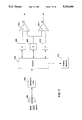
- FIG. 2 a block diagram of pacemaker 10 from FIG. 1 is shown.
- the present invention is described in conjunction with a pacemaker 10 having a microprocessor-based architecture, it will be understood that it could be implemented in any logic based, custom integrated circuit architecture, if desired. It will also be understood that the present invention may be utilized in conjunction with other implantable medical devices, such as cardioverters, defibrillators, neural stimulators, cardiac assist systems, and the like.
- pacemaker 10 includes an activity sensor 20, which may be, for example, a piezoelectric element bonded to the inside of the pacemaker's housing. Sensor 20 provides a sensor output which varies as a function of a measured parameter that relates to the metabolic requirements of patient 12.
- pacemaker 10 includes a pressure sensor 22 disposed at the distal end of lead 14, as previously noted, which may be similarly used to ascertain the metabolic requirements and/or cardiac output of patient 12.
- Pressure sensor 22 may be a piezoelectric element such as is disclosed in U.S. Pat. No. 4,407,296 to Anderson, entitled “Integral Hermetic Implantable Pressure Transducer," or U.S. Pat. No. 4,485,813 to Anderson et al., entitled “Implantable Dynamic Pressure Transducer System,” each assigned to the assignee of the present invention and incorporated herein by reference.
- Pacemaker 10 is schematically shown in FIG. 2 to be electrically coupled via a pacing lead 14 to a patient's heart 16.
- Lead 14 includes an intracardiac electrode 24 and pressure sensor 22 located near its distal end and positioned within the right ventricular (RV) chamber of heart 16.
- Lead 14 can carry either unipolar or bipolar electrodes as is well known in the art.
- lead 14 which couples pacemaker 10 to the ventricula endocardium can comprise a steroid-tipped, unipolar lead with an integral pressure transducer of the type described in the aforementioned references.
- Electrode 24 is coupled via suitable lead conductor 14a through input capacitor 26 to node 28 and to input/output terminals of an input/output circuit 30.
- Output from first sensor 20 is coupled to input/output circuit 30.
- Output from pressure sensor 22 is also coupled to input/output circuit 30 via suitable lead conductor 14b.
- Input/output circuit 30 contains the analog circuits for interface to the heart 16, activity sensor 20, pressure sensor 22, and antenna 52, as well as for the application of stimulating pulses to heart 16 to control its rate as a function thereof under control of the software-implemented algorithms in a microcomputer circuit 32.
- Microcomputer circuit 32 comprises an on-board circuit 34 and an off-board circuit 36.
- On-board circuit 34 includes a microprocessor 38, a system clock circuit 40, and on-board RAM 42 and ROM 44.
- Off-board circuit 36 includes an off-board RAM/ROM unit 46.
- Microcomputer circuit 32 is coupled by data communication bus 48 to a digital controller/timer circuit 50.
- Microcomputer circuit 32 may be fabricated of custom integrated circuit devices augmented by standard RAM/ROM components.
- Data communication bus 48 is also coupled to an analog memory integrated circuit 80 which includes a DAC 82, an address decode circuit 84, a sample and hold circuit 86, a high voltage supply and associated switches 88 and EEPROM memory cells 90.
- FIG. 2 the electrical components represented in FIG. 2 are powered by an appropriate implantable battery power source, not shown, in accordance with common practice in the art.
- a crystal oscillator circuit 56 typically a 32,768-Hz crystal-controlled oscillator, provides main timing clock signals to digital controller/timer circuit 50.
- a Vref/Bias circuit 58 generates a stable voltage reference and bias currents for the analog circuits of input/output circuit 30.
- An analog-to-digital converter/multiplexor (ADC/MUX) unit 60 digitizes analog signals and voltages to provide "real-time" telemetry of pressure and intracardiac signals and battery end-of-life (EOL) replacement function.
- ADC/MUX analog-to-digital converter/multiplexor
- the operating commands for controlling the timing of pacemaker 10 are coupled by bus 48 to digital controller/timer circuit 50 wherein digital timers and counters are employed to establish the overall escape interval of the pacemaker, as well as various refractory, blanking, and other timing windows for controlling the operation of the peripheral components within input/output circuit 30.
- Digital controller/timer circuit 50 is coupled to a sense amplifier 64 and an electrogram amplifier 66 for receiving amplified and processed signals picked up from electrode 24 through lead conductor 14a and capacitor 26 representative of the electrical activity of the patient's heart 16.
- Sense amplifier 64 amplifies sensed electrical cardiac signals and provides this amplified signal to peak sense and threshold measurement circuitry 65, which provides an indication of peak sensed voltages and the measured sense amplifier threshold voltage on multiple conductor signal path 67 to digital controller/timer circuit 50.
- the amplified sense amplifier signal is also provided to a comparator 69.
- the electrogram signal developed by EGM amplifier 66 is used in those occasions when the implanted device is being interrogated by an external programmer, not shown, in order to transmit by uplink telemetry a representation of the analog electrogram of the patient's electrical heart activity as described in U.S. Pat. No. 4,556,063, issued to Thompson et al., assigned to the assignee of the present invention and incorporated herein by reference.
- An output pulse generator 68 provides the pacing stimulus to the patient's heart 16 through coupling capacitor 74 in response to a pacing trigger signal developed by digital controller/timer circuit 50 each time the escape interval times out, or an externally transmitted pacing command has been received, or in response to other stored commands as is well known in the pacing art.
- Digital controller/timer circuit 50 is coupled to an activity circuit 70 for receiving, processing, and amplifying signals received from activity sensor 20.
- Activity circuit 70 produces an activity signal which is representative of the patient's metabolic requirements.
- digital controller/timer circuit 50 is coupled to a pressure circuit 72 for receiving, amplifying and processing sensor output from pressure sensor 22.
- pressure circuit 72 produces an amplified, filtered analog pressure signal which is received by digital controller/timer circuit 50.
- digital controller/timer circuit samples and digitizes the pressure signal from pressure circuit 72 to obtain a digital representation of the peak value of intracardiac pressure during each cardiac cycle. This value is provided to microprocessor 34, which maintains a running average over a previous number of cardiac cycles (e.g. sixteen) of the intracardiac pulse pressure.
- input/output circuit 30 further includes sensitivity control circuitry 75 coupled between digital controller/timer circuit 50 and sense amplifier circuit 64.
- Sensitivity control circuit 75 controls the sense amplifier gain and thus the sensing threshold of sense amplifier 64 as instructed by digital controller/timer circuit 50.
- digital to analog converter (DAC) 82 converts a digital representation of a signal into an analog signal.
- Address decode 84 controls the addressing of the row and column of analog memory 90 for both writing and reading data.
- Sample and hold circuit 86 samples an analog signal at a periodic rate to enable the storage of an analog signal in analog memory 90.
- High voltage (HV) and switch circuit 88 generates an approximate 20 volt DC voltage and, via the switches, stores a representation of an analog signal in analog memory 90.
- Analog memory 90 is a standard EEPROM memory utilized in this application to store analog signals.
- the data is stored in a section of analog memory 90 via address decode 84 and high voltage supply (HV) and switch circuit 88, all of FIG. 2.
- Digital data indicative of device function may also be stored interdispersed among the analog signal as herein described later in association with FIGS. 9 and 10.
- Analog memory 90 may be of the type incorporated in ISD 1016, a telecommunication monolithic integrated circuit from Information Storage Devices, Inc. A preliminary specification dated March, 1991 is incorporated herein by reference in its entirety.
- Analog data is continuously stored in a circular buffer (a section of analog memory 90), enabling 30 seconds of pre-event data to be frozen upon an event detection period.
- Automatic event detection is tested for in block 108 by microcomputer circuit 32 of FIG. 2 which monitors the intracardiac electrogram for arrhythmias, PVCs or runs of PVCs, as shown in co-pending U.S. patent application Ser. No. 07/881,996, filed on May 1, 1992 entitled “Diagnostic Function Data Storage and Telemetry Out for Rate Responsive Cardiac Pacemaker,” and assigned to the assignee of the present invention and incorporated herein by reference in its entirety.
- patient activation by reed switch closure with a hand-held magnet placed over the implant site may also trigger storage of signals.
- the analog data is converted to digital data at block 110 by 8 bit ADC 60 of FIG. 2.
- the sample and hold 104 and storage in buffer 106 are bypassed and the analog data is compressed in real-time.
- the digital data is compressed as will herein below be described.
- the compressed data is reconverted to analog voltage levels at block 114 via DAC 82 of FIG. 2.
- the marker data from the microcomputer 32 and the reconverted data from block 114 are stored in analog memory 90 via address decode 84 and high voltage supply (HV) and switch circuit 88, all of FIG. 2.
- a test for 2 more data values is evaluated at block 118. If ⁇ YES ⁇ , the flow diagram returns to block 110.
- five minutes of data may be stored along with the 30 seconds of pre-event data from the circular buffer and the time of occurrence from a system clock from microcomputer circuit 32 of FIG. 2.
- Nine separate events including pre-event, post-event and time of occurrence of each may be stored in an ISD 1016 (a 128K byte) analog memory 80. More or longer episodes may be stored if larger memory capacity or multiple integrated circuits are available.
- Memory 80 may operate in a freeze mode whereupon being filled with nine separate events, the data is frozen under command of microcomputer 32 until interrogation and reset by an external programmer, not shown.
- memory 80 may operate in a circular buffer or over-write mode whereby the most recent nine events will be stored in memory and may be read and reviewed by a clinician upon interrogation by the programmer. In either storage mode, the external programmer may reset and reinitiate the storage function under program commands as is well known in the art.
- the reading of the stored data from analog memory 90 is under control of microcomputer 32, address decode 84 and high voltage and switch circuit 88 whereby a specific memory bit is addressed and the analog signal is reconstructed sequentially, one bit at a time. This signal is routed through bus 48 to input/output circuit 30 for transmission to an external programmer (not shown) via RF transmit/receive circuit 54 and antenna 52.
- block 208 returns a ⁇ YES ⁇ and the larger of n 2 or n 3 is saved at block 210. If n 2 is smaller than n 1 , then the smaller of n 2 or n 3 is saved at block 220. More data is tested for at block 212. If at least 2 more data values are available, the flow diagram returns to block 206. If block 212 returns a ⁇ NO ⁇ , the COMPRESS -- CYCLE counter is incremented by 1. At block 216, if the COMPRESS -- CYCLE counter is greater than 2 the flow diagram is exited at block 218. If the COMPRESS -- CYCLE counter is less than, or equal to 2 the flow diagram returns to block 204.
- the flow diagram is serially repeated a second time on the data compressed and stored by the algorithm of FIG. 4 to enable the compression of data by a factor of 4 to 1.
- the flow diagram of FIG. 4 retains good fidelity by storing the maximum or minimum transition points in a waveform while reducing the stored data by 75%.
- FIG. 5 a flow diagram is shown which illustrates an alternative embodiment whereby the implantable device 10 of FIG. 1 incorporates an implantable 24 hour holter monitor.
- the signal to be stored may be one or both, the intracardiac signal from EGM amplifier 66 of FIG. 2 and/or the signal from a sensor such as the pressure sensor 22 shown in FIG. 2.
- the flow diagram is initiated at block 302 by the methods as herein described above (e.g. event detection, programming or patient activation).
- the analog signal is converted to a digital word in block 304 via the 8-bit ADC 60 of FIG. 2.
- the data is compressed via the technique as described herein above and shown in FIG. 4.
- the compressed digital data is reconverted to voltage levels via the DAC 82 shown in FIG.
- Block 310 the marker data from the microcomputer circuit 32 of FIG. 2 and the reconverted data from block 308 are stored in analog memory 90 of FIG. 2.
- a test for more data is evaluated at block 312. If ⁇ YES ⁇ , the flow diagram returns to block 304. If ⁇ NO ⁇ , the flow diagram exits at block 314.
- Block 310 may store data in a freeze mode or an over-write mode under control of microcomputer 32, FIG. 2.
- FIG. 6 a flow diagram is shown which illustrates an alternative embodiment whereby the implantable device 10, FIG. 1, incorporates storage of analog EGM data directly without an intervening conversion to digital data and subsequent reconversion to analog data.
- the signal to be stored may be one or both, the intracardiac signal from EGM amplifier 66 of FIG. 2 and/or the signal from a sensor such as the pressure sensor 22 shown in FIG. 2.
- the flow diagram is initiated at block 402 by the methods as described herein above (e.g. event detection, programming or patient activation).
- the analog data is sampled and held at block 404 by a sample and hold circuit 86 of FIG. 2. The sampling may occur at a 128 Hz rate for adequate clinically useful data.
- the data is stored in analog memory 90 via address control 84 and high voltage supply (HV) and switches 88 of FIG. 2.
- HV high voltage supply
- a test for more data is entered. If ⁇ YES ⁇ , the flow diagram returns to sample and hold block 404. If ⁇ NO ⁇ , the flow diagram is exited at block 410.
- This embodiment is simpler, requires less circuitry and less current drain from the battery because of the elimination of the analog to digital conversion 304, the compression of data 306 and the digital to analog conversion 308 from FIG. 5. The embodiment shown in FIG. 6 will have improved fidelity and will compress data to 8:1 versus a digital equivalent.
- FIG. 7 a block diagram is shown which illustrates an alternative embodiment whereby the implantable device 10, FIG. 1, incorporates the storage and compression of analog data without the conversion of the analog data to digital data and the subsequent reconversion to analog data as described in the embodiment of FIG. 5.
- the signal to be stored may be one or both, the intracardiac signal from EGM amplifier 66 of FIG. 2 and/or the signal from a sensor such as the pressure sensor 22 shown in FIG. 2.
- a sample and hold circuit 502 sampled at a 128 Hz rate, generates analog voltage data that is stored temporarily in analog memory cells 506, 508, and 510 under control of MUX control circuit 504.
- the first analog voltage value/data is stored in cell 510 and in the first memory location.
- the next two data samples are stored in cells 506 and 508, respectively.
- Comparator 512 compares the voltage level of analog cells 506 and 508 indicating, by a true logic level, if the voltage in cell 506 is greater than 508. Alternatively, a false logic level indicates that the voltage in cell 508 is greater than the voltage in cell 506.
- comparator 514 compares the voltage level of analog cells 508 and 510 indicating by a true logic level if the voltage in cell 508 is greater than 510. Alternatively, a false logic level indicates that the voltage in cell 510 is greater than the voltage in cell 508.
- Microcomputer 32, FIG. 2 determines by a simple process flow, shown in FIG. 8, which value is stored in analog memory 516 by control/MUX circuit 504.
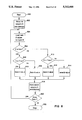
- FIG. 8 a block diagram is shown which illustrates a flow diagram associated with the compression of data from FIG. 7.
- the flow diagram of FIG. 8 begins by initiating the compression process at block 600 by event detection 104 of FIG. 3.
- the first data value (C) is stored in temporary cell 510 and the first address in memory in block 602.
- the next two values of data are stored in cells 508 (B) and 506 (A) respectively by block 624.
- comparator 514 is ⁇ TRUE ⁇ at block 604
- the flow diagram tests if comparator 512 (D) is TRUE in block 606. If ⁇ TRUE ⁇ , the analog value stored in 506 is stored in memory and in cell 510 by block 618.
- comparator 514 (E) is ⁇ FALSE ⁇
- the analog value stored in cell 508 is stored in memory and cell 510 by block 618.
- comparator 514 is ⁇ FALSE ⁇ and comparator 512 is ⁇ TRUE ⁇
- the analog value in cell 506 is stored in memory and cell 510 at block 618.
- comparator 512 is ⁇ FALSE ⁇
- Block 620 tests for 2 more data values; if ⁇ YES ⁇ , the flow diagram returns to block 624. If ⁇ NO ⁇ , the compression process exits and stops at block 622.
- the analog data is converted to a signal for transmission to an external peripheral, such as a programmer, at a subsequent follow-up either via a clinic or hospital office visit or transtelephonically.
- Telemetry techniques are well known to those skilled in the art. Specific reference is made to converting the stored analog voltage to a pulse position modulated format as taught in Medtronic U.S. Pat. No. 4,556,063 to Thompson et. al, and incorporated herein by reference.
- the stored analog voltage may be digitized by an ADC and transmitted via the method taught in copending U.S. patent application Ser. No. 07/468,407 filed on Jan.
- the high data rate telemetry system of the '407 application would be a preferred method for transmitting the stored data to a peripheral allowing data to be stored at a low rate (e.g., 32 samples per second to even one sample per hour or per day) and transmitted to a peripheral at a very high rate.
- a low rate e.g. 32 samples per second to even one sample per hour or per day
- FIGS. 9 and 10 demonstrate the incorporation of marker or event indication information into the stored data.
- a marker indication of device function is entered into the stored analog data stream by utilizing a single bit indicator of -V MAX followed by a selectable voltage value indicating a marker of specific device function.
- intracardiac signal data is lost when digital marker information is simultaneously transmitted with the intracardiac signal because signal data bits are removed and replaced with digital data indicative of device function.
- FIG. 9 shows an example of the stored voltage 700 in the preferred embodiment of FIG. 3.
- the marker indicator of -30 mVolts (-V MAX ) is indicated.
- a value of -10 mVolts indicates a ventricular event.
- DDD dual chamber
- FIG. 10 shows the reconstructed and displayed EGM signal 802 with a ventricular sense (V Sense ) marker indicator 800 displayed on an external peripheral/programmer graphics screen or printed or plotted to a paper hardcopy. Note that the marker information has been removed from the analog data signal and the adjacent analog data points reconnected. Similarly, the time of occurrence of each stored event may be encoded and stored as herein described above.
- V Sense ventricular sense
- a stored arrhythmia episode may be processed by microcomputer 32 to initiate a pacing, cardioversion or defibrillation therapy as is known in the art.
- a stored signal indicative of capture, non-capture or a fusion beat may be compared on a periodic, or a beat-by-beat basis to the signal seen by the sense amplifier 64 after a pacing stimulus from output circuit 68. If an evoked response is not indicated (non-capture), the output stimulus pulse width and/or amplitude may be increased to regain capture as disclosed in U.S. Pat. No. 4,858,610 issued to Callaghan, et al., U.S. Pat.
- the compression function may be performed by microcomputer 32 by pattern matching the periodic signal within a window from 5 to 80 mSec after output stimulus to the stored representation of the signal indicative of capture.
- the negative magnitude of the stored non-capture signal may be summed with the periodic signal with the resultant signal being indicative of an evoked response, if present.
Abstract
Description
______________________________________
Event            Voltage
______________________________________
.sup.V Sense     -10 mV
.sup.V Refractory Sense
                 -20 mV
.sup.V Pace      -30 mV
.sup.A Sense     +10 mV
.sup.A Refractory Sense
                 +20 mV
.sup.A Pace      +30 mV
______________________________________
Claims (19)
Priority Applications (7)
| Application Number | Priority Date | Filing Date | Title |
|---|---|---|---|
| US07/935,953 US5312446A (en) | 1992-08-26 | 1992-08-26 | Compressed storage of data in cardiac pacemakers |
| CA002120243A CA2120243C (en) | 1992-08-26 | 1993-07-23 | Compressed storage of data in cardiac pacemakers |
| PCT/US1993/006907 WO1994005371A1 (en) | 1992-08-26 | 1993-07-23 | Compressed storage of data in cardiac pacemakers |
| JP6507172A JP2939660B2 (en) | 1992-08-26 | 1993-07-23 | Medical device that can be implanted under the skin |
| DE69329526T DE69329526T2 (en) | 1992-08-26 | 1993-07-23 | STORAGE OF DATA IN HEART PACEMAKERS |
| AU46870/93A AU654446B2 (en) | 1992-08-26 | 1993-07-23 | Compressed storage of data in cardiac pacemakers |
| EP93917318A EP0613390B1 (en) | 1992-08-26 | 1993-07-23 | Storage of data in cardiac pacemakers |
Applications Claiming Priority (1)
| Application Number | Priority Date | Filing Date | Title |
|---|---|---|---|
| US07/935,953 US5312446A (en) | 1992-08-26 | 1992-08-26 | Compressed storage of data in cardiac pacemakers |
Publications (1)
| Publication Number | Publication Date |
|---|---|
| US5312446A true US5312446A (en) | 1994-05-17 |
Family
ID=25467960
Family Applications (1)
| Application Number | Title | Priority Date | Filing Date |
|---|---|---|---|
| US07/935,953 Expired - Lifetime US5312446A (en) | 1992-08-26 | 1992-08-26 | Compressed storage of data in cardiac pacemakers |
Country Status (7)
| Country | Link |
|---|---|
| US (1) | US5312446A (en) |
| EP (1) | EP0613390B1 (en) |
| JP (1) | JP2939660B2 (en) |
| AU (1) | AU654446B2 (en) |
| CA (1) | CA2120243C (en) |
| DE (1) | DE69329526T2 (en) |
| WO (1) | WO1994005371A1 (en) |
Cited By (130)
| Publication number | Priority date | Publication date | Assignee | Title |
|---|---|---|---|---|
| US5391188A (en) * | 1992-05-01 | 1995-02-21 | Medtronic, Inc. | Low cost implantable medical device |
| US5518001A (en) * | 1994-06-17 | 1996-05-21 | Pacesetter, Inc. | Cardiac device with patient-triggered storage of physiological sensor data |
| EP0793980A2 (en) * | 1996-03-04 | 1997-09-10 | BIOTRONIK Mess- und Therapiegeräte GmbH & Co Ingenieurbüro Berlin | Signal storage device in an implantable medical apparatus |
| US5693076A (en) * | 1996-01-16 | 1997-12-02 | Medtronic, Inc. | Compressed patient narrative storage in and full text reconstruction from implantable medical devices |
| US5727552A (en) * | 1996-01-11 | 1998-03-17 | Medtronic, Inc. | Catheter and electrical lead location system |
| US5732708A (en) * | 1996-08-09 | 1998-03-31 | Pacesetter, Inc. | Method for storing EGM and diagnostic data in a read/write memory of an implantable cardiac therapy device |
| US5785660A (en) * | 1996-03-28 | 1998-07-28 | Pacesetter, Inc. | Methods and apparatus for storing intracardiac electrograms |
| US5819740A (en) * | 1995-11-22 | 1998-10-13 | Medtronic, Inc. | System and method for compressing digitized signals in implantable and battery powered devices |
| US5836982A (en) * | 1997-02-19 | 1998-11-17 | Medtronic, Inc. | System and method of data compression and non-linear sampling for implantable and battery-powered devices |
| US5861013A (en) * | 1997-04-29 | 1999-01-19 | Medtronic Inc. | Peak tracking capture detection circuit and method |
| US5871512A (en) * | 1997-04-29 | 1999-02-16 | Medtronic, Inc. | Microprocessor capture detection circuit and method |
| US5944745A (en) * | 1996-09-25 | 1999-08-31 | Medtronic, Inc. | Implantable medical device capable of prioritizing diagnostic data and allocating memory for same |
| US5954756A (en) * | 1998-04-09 | 1999-09-21 | Medtronic, Inc. | Microprocessor capture detection circuit and method |
| WO1999058056A1 (en) | 1998-05-13 | 1999-11-18 | Medtronic, Inc. | Implantable medical device for tracking patient functional status |
| US6038474A (en) * | 1999-03-02 | 2000-03-14 | Cardiac Pacemakers, Inc. | Pseudo-fusion management during automatic capture verification |
| US6068651A (en) * | 1998-03-26 | 2000-05-30 | Pacesetter, Inc. | Atrial defibrillation lock out feature |
| WO2000051680A1 (en) | 1999-03-05 | 2000-09-08 | Medtronic, Inc. | Method and apparatus for monitoring heart rate |
| US6190324B1 (en) | 1999-04-28 | 2001-02-20 | Medtronic, Inc. | Implantable medical device for tracking patient cardiac status |
| US6200265B1 (en) | 1999-04-16 | 2001-03-13 | Medtronic, Inc. | Peripheral memory patch and access method for use with an implantable medical device |
| US6230059B1 (en) | 1999-03-17 | 2001-05-08 | Medtronic, Inc. | Implantable monitor |
| WO2001070331A2 (en) | 2000-03-20 | 2001-09-27 | Medtronic, Inc. | Method and apparatus for monitoring physiologic parameters in conjunction with a treatment regimen |
| US6317626B1 (en) | 1999-11-03 | 2001-11-13 | Medtronic, Inc. | Method and apparatus for monitoring heart rate |
| US6385485B1 (en) * | 1999-12-20 | 2002-05-07 | Ela Medical S.A. | Continuously monitoring cardiac events in an active implantable medical device |
| WO2002056961A2 (en) | 2000-11-28 | 2002-07-25 | Medtronic, Inc. | Method and apparatus for discrimination of atrial fibrillation using ventricular rate detection |
| US6473649B1 (en) | 1999-12-22 | 2002-10-29 | Cardiac Pacemakers, Inc. | Rate management during automatic capture verification |
| US20020188773A1 (en) * | 2001-04-30 | 2002-12-12 | Frederik Augustijn | Method and system for transferring and storing data in a medical device with limited storage and memory |
| US6564807B1 (en) * | 1997-02-26 | 2003-05-20 | Alfred E. Mann Foundation For Scientific Research | System of implantable devices for monitoring and/or affecting body parameters |
| US6582365B1 (en) * | 1998-07-09 | 2003-06-24 | The United States Of America As Represented By The Administrator Of The National Aeronautics And Space Administration | Advanced sensor systems for biotelemetry |
| US6599242B1 (en) | 2000-07-19 | 2003-07-29 | Medtronic, Inc. | Method and apparatus for data compression of heart signals |
| US6649078B2 (en) | 2000-12-06 | 2003-11-18 | The Regents Of The University Of California | Thin film capillary process and apparatus |
| US6690959B2 (en) | 2000-09-01 | 2004-02-10 | Medtronic, Inc. | Skin-mounted electrodes with nano spikes |
| US6714811B1 (en) | 1999-03-05 | 2004-03-30 | Medtronic, Inc. | Method and apparatus for monitoring heart rate |
| US6719689B2 (en) * | 2001-04-30 | 2004-04-13 | Medtronic, Inc. | Method and system for compressing and storing data in a medical device having limited storage |
| US20040103906A1 (en) * | 1997-02-26 | 2004-06-03 | Schulman Joseph H. | Battery-powered patient implantable device |
| US6760615B2 (en) | 2001-10-31 | 2004-07-06 | Medtronic, Inc. | Method and apparatus for discriminating between tachyarrhythmias |
| US6766190B2 (en) | 2001-10-31 | 2004-07-20 | Medtronic, Inc. | Method and apparatus for developing a vectorcardiograph in an implantable medical device |
| US20050049647A1 (en) * | 2003-08-29 | 2005-03-03 | Olson Walter H. | Subcutaneous switch for implantable medical device |
| US20050137627A1 (en) * | 2003-12-22 | 2005-06-23 | Koshiol Allan T. | Synchronizing continuous signals and discrete events for an implantable medical device |
| US20050171448A1 (en) * | 2004-02-02 | 2005-08-04 | Lev Korzinov | Biological signal management |
| US20050245794A1 (en) * | 2004-04-29 | 2005-11-03 | Medtronic, Inc. | Communication with implantable monitoring probe |
| US7027858B2 (en) | 2002-09-11 | 2006-04-11 | Medtronic, Inc. | Methods and apparatus for cardiac R-wave sensing in a subcutaneous ECG waveform |
| US7031765B2 (en) | 2002-11-11 | 2006-04-18 | Medtronic, Inc | Algorithms for detecting atrial arrhythmias from discriminatory signatures of ventricular cycle lengths |
| US20060094972A1 (en) * | 2004-11-02 | 2006-05-04 | Medtronic, Inc. | Techniques for user-activated data retention in an implantable medical device |
| US20060095092A1 (en) * | 2004-11-02 | 2006-05-04 | Medtronic, Inc. | Techniques for data reporting in an implantable medical device |
| US20060094968A1 (en) * | 2004-11-01 | 2006-05-04 | Drew Touby A | Data compression method for implantable medical devices |
| US20060195039A1 (en) * | 2004-11-02 | 2006-08-31 | Medtronic, Inc. | Clustering with combined physiological signals |
| US20060235489A1 (en) * | 2004-11-02 | 2006-10-19 | Medtronic, Inc. | Patient event marking in combination with physiological signals |
| US7167755B2 (en) | 2004-10-05 | 2007-01-23 | Cardiac Pacemakers, Inc. | Adaptive software configuration for a medical device |
| US20070129774A1 (en) * | 2005-12-02 | 2007-06-07 | Medtronic, Inc. | Closed-loop therapy adjustment |
| US20070150026A1 (en) * | 2005-12-02 | 2007-06-28 | Medtronic, Inc. | Closed-loop therapy adjustment |
| US20070150029A1 (en) * | 2005-12-02 | 2007-06-28 | Medtronic, Inc. | Closed-loop therapy adjustment |
| US7286872B2 (en) | 2003-10-07 | 2007-10-23 | Cardiac Pacemakers, Inc. | Method and apparatus for managing data from multiple sensing channels |
| US20070255155A1 (en) * | 2006-04-27 | 2007-11-01 | Medtronic, Inc. | Method and system for loop recording with overlapping events |
| US20070255531A1 (en) * | 2006-04-27 | 2007-11-01 | Medtronic, Inc. | Peak data retention of signal data in an implantable medical device |
| US7294108B1 (en) | 2005-01-27 | 2007-11-13 | Pacesetter, Inc. | Cardiac event microrecorder and method for implanting same |
| US20080058651A1 (en) * | 2006-09-05 | 2008-03-06 | Cardiac Pacemakers, Inc. | Implantable Medical Device Diagnostic Data Acquisition and Storage |
| US20080119758A1 (en) * | 2006-11-20 | 2008-05-22 | Radi Medical Systems Ab | Transceiver unit in a pressure measurement system |
| US7450998B2 (en) | 2003-11-21 | 2008-11-11 | Alfred E. Mann Foundation For Scientific Research | Method of placing an implantable device proximate to neural/muscular tissue |
| US20090228073A1 (en) * | 2008-03-07 | 2009-09-10 | Patrick Scholten | Implantable medical device with patient input mechanism |
| US7621905B2 (en) | 1997-12-30 | 2009-11-24 | Remon Medical Technologies Ltd. | Devices for intrabody delivery of molecules and systems and methods utilizing same |
| US7641619B2 (en) | 2000-10-16 | 2010-01-05 | Remon Medical Technologies, Ltd. | Barometric pressure correction based on remote sources of information |
| US20100010575A1 (en) * | 2008-07-11 | 2010-01-14 | Medtronic, Inc. | Patient interaction with posture-responsive therapy |
| US20100010389A1 (en) * | 2008-07-11 | 2010-01-14 | Medtronic, Inc. | Generation of proportional posture information over multiple time intervals |
| US20100010390A1 (en) * | 2008-07-11 | 2010-01-14 | Medtronic, Inc. | Dwell time adjustments for posture state-responsive therapy |
| US20100010578A1 (en) * | 2008-07-11 | 2010-01-14 | Medtronic, Inc. | Patient assignment of therapy parameter to posture state |
| US7764988B2 (en) | 2006-04-27 | 2010-07-27 | Medtronic, Inc. | Flexible memory management scheme for loop recording in an implantable device |
| US7813808B1 (en) | 2004-11-24 | 2010-10-12 | Remon Medical Technologies Ltd | Implanted sensor system with optimized operational and sensing parameters |
| US20100280330A1 (en) * | 2006-11-20 | 2010-11-04 | St. Jude Medical Systems Ab | Transceiver unit in a measurement system |
| US20100286536A1 (en) * | 2006-11-20 | 2010-11-11 | St. Jude Medical Systems Ab | Transceiver unit in a measurement system |
| US20100312301A1 (en) * | 2009-06-03 | 2010-12-09 | Cardiac Pacemakers, Inc. | System and method for monitoring cardiovascular pressure |
| US20110112416A1 (en) * | 2009-11-10 | 2011-05-12 | Makor Issues And Rights Ltd. | System and apparatus for providing diagnosis and personalized abnormalities alerts and for providing adaptive responses in clinical trials |
| US7955268B2 (en) | 2006-07-21 | 2011-06-07 | Cardiac Pacemakers, Inc. | Multiple sensor deployment |
| US8115635B2 (en) | 2005-02-08 | 2012-02-14 | Abbott Diabetes Care Inc. | RF tag on test strips, test strip vials and boxes |
| US8150531B2 (en) | 2008-07-11 | 2012-04-03 | Medtronic, Inc. | Associating therapy adjustments with patient posture states |
| US8175720B2 (en) | 2009-04-30 | 2012-05-08 | Medtronic, Inc. | Posture-responsive therapy control based on patient input |
| US8231555B2 (en) | 2009-04-30 | 2012-07-31 | Medtronic, Inc. | Therapy system including multiple posture sensors |
| US8271093B2 (en) | 2004-09-17 | 2012-09-18 | Cardiac Pacemakers, Inc. | Systems and methods for deriving relative physiologic measurements using a backend computing system |
| US8280517B2 (en) | 2008-09-19 | 2012-10-02 | Medtronic, Inc. | Automatic validation techniques for validating operation of medical devices |
| US8388555B2 (en) | 2010-01-08 | 2013-03-05 | Medtronic, Inc. | Posture state classification for a medical device |
| US8396565B2 (en) | 2003-09-15 | 2013-03-12 | Medtronic, Inc. | Automatic therapy adjustments |
| US8401666B2 (en) | 2008-07-11 | 2013-03-19 | Medtronic, Inc. | Modification profiles for posture-responsive therapy |
| US8504150B2 (en) | 2008-07-11 | 2013-08-06 | Medtronic, Inc. | Associating therapy adjustments with posture states using a stability timer |
| US8579834B2 (en) | 2010-01-08 | 2013-11-12 | Medtronic, Inc. | Display of detected patient posture state |
| US8649860B2 (en) | 2009-05-27 | 2014-02-11 | Cardiac Pacemakers, Inc. | Adaptive event storage in implantable device |
| US8708934B2 (en) | 2008-07-11 | 2014-04-29 | Medtronic, Inc. | Reorientation of patient posture states for posture-responsive therapy |
| US8757485B2 (en) | 2012-09-05 | 2014-06-24 | Greatbatch Ltd. | System and method for using clinician programmer and clinician programming data for inventory and manufacturing prediction and control |
| US8761897B2 (en) | 2012-08-31 | 2014-06-24 | Greatbatch Ltd. | Method and system of graphical representation of lead connector block and implantable pulse generators on a clinician programmer |
| US8812125B2 (en) | 2012-08-31 | 2014-08-19 | Greatbatch Ltd. | Systems and methods for the identification and association of medical devices |
| US8868199B2 (en) | 2012-08-31 | 2014-10-21 | Greatbatch Ltd. | System and method of compressing medical maps for pulse generator or database storage |
| US8903496B2 (en) | 2012-08-31 | 2014-12-02 | Greatbatch Ltd. | Clinician programming system and method |
| US8983616B2 (en) | 2012-09-05 | 2015-03-17 | Greatbatch Ltd. | Method and system for associating patient records with pulse generators |
| WO2015077568A1 (en) | 2013-11-21 | 2015-05-28 | Medtronic, Inc. | Method and apparatus for accurately determining heart rate variability and sympathetic reserve |
| US9050471B2 (en) | 2008-07-11 | 2015-06-09 | Medtronic, Inc. | Posture state display on medical device user interface |
| US9180302B2 (en) | 2012-08-31 | 2015-11-10 | Greatbatch Ltd. | Touch screen finger position indicator for a spinal cord stimulation programming device |
| US9259577B2 (en) | 2012-08-31 | 2016-02-16 | Greatbatch Ltd. | Method and system of quick neurostimulation electrode configuration and positioning |
| US9327070B2 (en) | 2009-04-30 | 2016-05-03 | Medtronic, Inc. | Medical device therapy based on posture and timing |
| US9357949B2 (en) | 2010-01-08 | 2016-06-07 | Medtronic, Inc. | User interface that displays medical therapy and posture data |
| US9375582B2 (en) | 2012-08-31 | 2016-06-28 | Nuvectra Corporation | Touch screen safety controls for clinician programmer |
| US20160213268A1 (en) * | 2013-09-09 | 2016-07-28 | Agency For Science, Technology And Research | Device for detecting a spike in one of a plurality of neural signals |
| US9471753B2 (en) | 2012-08-31 | 2016-10-18 | Nuvectra Corporation | Programming and virtual reality representation of stimulation parameter Groups |
| US9507912B2 (en) | 2012-08-31 | 2016-11-29 | Nuvectra Corporation | Method and system of simulating a pulse generator on a clinician programmer |
| US9566441B2 (en) | 2010-04-30 | 2017-02-14 | Medtronic, Inc. | Detecting posture sensor signal shift or drift in medical devices |
| US9594877B2 (en) | 2012-08-31 | 2017-03-14 | Nuvectra Corporation | Virtual reality representation of medical devices |
| US9615788B2 (en) | 2012-08-31 | 2017-04-11 | Nuvectra Corporation | Method and system of producing 2D representations of 3D pain and stimulation maps and implant models on a clinician programmer |
| US9737719B2 (en) | 2012-04-26 | 2017-08-22 | Medtronic, Inc. | Adjustment of therapy based on acceleration |
| US9767255B2 (en) | 2012-09-05 | 2017-09-19 | Nuvectra Corporation | Predefined input for clinician programmer data entry |
| US9907959B2 (en) | 2012-04-12 | 2018-03-06 | Medtronic, Inc. | Velocity detection for posture-responsive therapy |
| US9956418B2 (en) | 2010-01-08 | 2018-05-01 | Medtronic, Inc. | Graphical manipulation of posture zones for posture-responsive therapy |
| US10639488B2 (en) | 2015-02-23 | 2020-05-05 | Cardiac Pacemakers, Inc. | Tap sensor-enabled IMD |
| US10668276B2 (en) | 2012-08-31 | 2020-06-02 | Cirtec Medical Corp. | Method and system of bracketing stimulation parameters on clinician programmers |
| US11234650B2 (en) | 2006-11-20 | 2022-02-01 | St. Jude Medical Coordination Center Bvba | Measurement system |
| US20230019441A1 (en) * | 2013-09-25 | 2023-01-19 | Bardy Diagnostics, Inc. | Subcutaneous electrocardiography monitor configured for test-based data compression |
| US11647939B2 (en) | 2013-09-25 | 2023-05-16 | Bardy Diagnostics, Inc. | System and method for facilitating a cardiac rhythm disorder diagnosis with the aid of a digital computer |
| US11647941B2 (en) | 2013-09-25 | 2023-05-16 | Bardy Diagnostics, Inc. | System and method for facilitating a cardiac rhythm disorder diagnosis with the aid of a digital computer |
| US11653868B2 (en) | 2013-09-25 | 2023-05-23 | Bardy Diagnostics, Inc. | Subcutaneous insertable cardiac monitor optimized for electrocardiographic (ECG) signal acquisition |
| US11653869B2 (en) | 2013-09-25 | 2023-05-23 | Bardy Diagnostics, Inc. | Multicomponent electrocardiography monitor |
| US11653870B2 (en) | 2013-09-25 | 2023-05-23 | Bardy Diagnostics, Inc. | System and method for display of subcutaneous cardiac monitoring data |
| US11653880B2 (en) | 2019-07-03 | 2023-05-23 | Bardy Diagnostics, Inc. | System for cardiac monitoring with energy-harvesting-enhanced data transfer capabilities |
| US11660035B2 (en) | 2013-09-25 | 2023-05-30 | Bardy Diagnostics, Inc. | Insertable cardiac monitor |
| US11660037B2 (en) | 2013-09-25 | 2023-05-30 | Bardy Diagnostics, Inc. | System for electrocardiographic signal acquisition and processing |
| US11678832B2 (en) | 2013-09-25 | 2023-06-20 | Bardy Diagnostics, Inc. | System and method for atrial fibrillation detection in non-noise ECG data with the aid of a digital computer |
| US11678830B2 (en) | 2017-12-05 | 2023-06-20 | Bardy Diagnostics, Inc. | Noise-separating cardiac monitor |
| US11678798B2 (en) | 2019-07-03 | 2023-06-20 | Bardy Diagnostics Inc. | System and method for remote ECG data streaming in real-time |
| US11696681B2 (en) | 2019-07-03 | 2023-07-11 | Bardy Diagnostics Inc. | Configurable hardware platform for physiological monitoring of a living body |
| US11701045B2 (en) | 2013-09-25 | 2023-07-18 | Bardy Diagnostics, Inc. | Expended wear ambulatory electrocardiography monitor |
| US11723575B2 (en) | 2013-09-25 | 2023-08-15 | Bardy Diagnostics, Inc. | Electrocardiography patch |
| US11744513B2 (en) | 2013-09-25 | 2023-09-05 | Bardy Diagnostics, Inc. | Electrocardiography and respiratory monitor |
| US11786159B2 (en) | 2013-09-25 | 2023-10-17 | Bardy Diagnostics, Inc. | Self-authenticating electrocardiography and physiological sensor monitor |
| US11826151B2 (en) | 2013-09-25 | 2023-11-28 | Bardy Diagnostics, Inc. | System and method for physiological data classification for use in facilitating diagnosis |
| US11918364B2 (en) | 2013-09-25 | 2024-03-05 | Bardy Diagnostics, Inc. | Extended wear ambulatory electrocardiography and physiological sensor monitor |
Families Citing this family (1)
| Publication number | Priority date | Publication date | Assignee | Title |
|---|---|---|---|---|
| US11857793B2 (en) * | 2020-06-10 | 2024-01-02 | Medtronic, Inc. | Managing storage of sensed information |
Citations (12)
| Publication number | Priority date | Publication date | Assignee | Title |
|---|---|---|---|---|
| US4223678A (en) * | 1978-05-03 | 1980-09-23 | Mieczyslaw Mirowski | Arrhythmia recorder for use with an implantable defibrillator |
| US4295474A (en) * | 1979-10-02 | 1981-10-20 | The Johns Hopkins University | Recorder with patient alarm and service request systems suitable for use with automatic implantable defibrillator |
| US4407288A (en) * | 1981-02-18 | 1983-10-04 | Mieczyslaw Mirowski | Implantable heart stimulator and stimulation method |
| US4407296A (en) * | 1980-09-12 | 1983-10-04 | Medtronic, Inc. | Integral hermetic impantable pressure transducer |
| US4485813A (en) * | 1981-11-19 | 1984-12-04 | Medtronic, Inc. | Implantable dynamic pressure transducer system |
| US4556063A (en) * | 1980-10-07 | 1985-12-03 | Medtronic, Inc. | Telemetry system for a medical device |
| US4625730A (en) * | 1985-04-09 | 1986-12-02 | The Johns Hopkins University | Patient ECG recording control for an automatic implantable defibrillator |
| US4729376A (en) * | 1985-05-28 | 1988-03-08 | Cordis Corporation | Cardiac pacer and method providing means for periodically determining capture threshold and adjusting pulse output level accordingly |
| US4800883A (en) * | 1986-04-02 | 1989-01-31 | Intermedics, Inc. | Apparatus for generating multiphasic defibrillation pulse waveform |
| US4858610A (en) * | 1985-12-11 | 1989-08-22 | Telectronics, N.V. | Detection of cardiac evoked potentials |
| US4878497A (en) * | 1988-03-25 | 1989-11-07 | Telectronics N.V. | Pacemaker with improved automatic output regulation |
| US5127404A (en) * | 1990-01-22 | 1992-07-07 | Medtronic, Inc. | Telemetry format for implanted medical device |
Family Cites Families (6)
| Publication number | Priority date | Publication date | Assignee | Title |
|---|---|---|---|---|
| US3847346A (en) * | 1972-08-30 | 1974-11-12 | Scanner | Data field recognition and reading method and system |
| SE7402575L (en) * | 1974-02-27 | 1975-08-28 | Asea Ab | |
| SU878309A1 (en) * | 1980-01-03 | 1981-11-07 | Предприятие П/Я А-1882 | Defibrillator |
| US4716903A (en) * | 1986-10-06 | 1988-01-05 | Telectronics N.V. | Storage in a pacemaker memory |
| JPH0338791A (en) * | 1989-06-30 | 1991-02-19 | Veritel Inc | Symbol for confirmation and confirmation device thereof |
| US5080096A (en) * | 1990-07-06 | 1992-01-14 | Medtronic, Inc. | Method and apparatus for accessing a nonvolatile memory |
-
1992
- 1992-08-26 US US07/935,953 patent/US5312446A/en not_active Expired - Lifetime
-
1993
- 1993-07-23 AU AU46870/93A patent/AU654446B2/en not_active Ceased
- 1993-07-23 EP EP93917318A patent/EP0613390B1/en not_active Expired - Lifetime
- 1993-07-23 CA CA002120243A patent/CA2120243C/en not_active Expired - Fee Related
- 1993-07-23 JP JP6507172A patent/JP2939660B2/en not_active Expired - Fee Related
- 1993-07-23 WO PCT/US1993/006907 patent/WO1994005371A1/en active IP Right Grant
- 1993-07-23 DE DE69329526T patent/DE69329526T2/en not_active Expired - Fee Related
Patent Citations (13)
| Publication number | Priority date | Publication date | Assignee | Title |
|---|---|---|---|---|
| US4223678A (en) * | 1978-05-03 | 1980-09-23 | Mieczyslaw Mirowski | Arrhythmia recorder for use with an implantable defibrillator |
| US4295474A (en) * | 1979-10-02 | 1981-10-20 | The Johns Hopkins University | Recorder with patient alarm and service request systems suitable for use with automatic implantable defibrillator |
| US4407296A (en) * | 1980-09-12 | 1983-10-04 | Medtronic, Inc. | Integral hermetic impantable pressure transducer |
| US4556063A (en) * | 1980-10-07 | 1985-12-03 | Medtronic, Inc. | Telemetry system for a medical device |
| US4407288B1 (en) * | 1981-02-18 | 2000-09-19 | Mieczyslaw Mirowski | Implantable heart stimulator and stimulation method |
| US4407288A (en) * | 1981-02-18 | 1983-10-04 | Mieczyslaw Mirowski | Implantable heart stimulator and stimulation method |
| US4485813A (en) * | 1981-11-19 | 1984-12-04 | Medtronic, Inc. | Implantable dynamic pressure transducer system |
| US4625730A (en) * | 1985-04-09 | 1986-12-02 | The Johns Hopkins University | Patient ECG recording control for an automatic implantable defibrillator |
| US4729376A (en) * | 1985-05-28 | 1988-03-08 | Cordis Corporation | Cardiac pacer and method providing means for periodically determining capture threshold and adjusting pulse output level accordingly |
| US4858610A (en) * | 1985-12-11 | 1989-08-22 | Telectronics, N.V. | Detection of cardiac evoked potentials |
| US4800883A (en) * | 1986-04-02 | 1989-01-31 | Intermedics, Inc. | Apparatus for generating multiphasic defibrillation pulse waveform |
| US4878497A (en) * | 1988-03-25 | 1989-11-07 | Telectronics N.V. | Pacemaker with improved automatic output regulation |
| US5127404A (en) * | 1990-01-22 | 1992-07-07 | Medtronic, Inc. | Telemetry format for implanted medical device |
Non-Patent Citations (4)
| Title |
|---|
| Edited by Barold et al., "Memory Technology and Implantable Holter Systems", Advances in Technology and Clinical Applications: The Third Decade of Cardiac Pacing, Chapter Three, Part IV, Futura Publishing Company, Mount Kisco, N.Y., 1982. |
| Edited by Barold et al., Memory Technology and Implantable Holter Systems , Advances in Technology and Clinical Applications: The Third Decade of Cardiac Pacing, Chapter Three, Part IV, Futura Publishing Company, Mount Kisco, N.Y., 1982. * |
| Thomas J. Lynch, Ph.D., Data Compression Techniques and Applications, Van Nostrand Reinhold Company, New York, pp. 256 259. * |
| Thomas J. Lynch, Ph.D., Data Compression Techniques and Applications, Van Nostrand Reinhold Company, New York, pp. 256-259. |
Cited By (262)
| Publication number | Priority date | Publication date | Assignee | Title |
|---|---|---|---|---|
| US5391188A (en) * | 1992-05-01 | 1995-02-21 | Medtronic, Inc. | Low cost implantable medical device |
| US5518001A (en) * | 1994-06-17 | 1996-05-21 | Pacesetter, Inc. | Cardiac device with patient-triggered storage of physiological sensor data |
| US5819740A (en) * | 1995-11-22 | 1998-10-13 | Medtronic, Inc. | System and method for compressing digitized signals in implantable and battery powered devices |
| US5727552A (en) * | 1996-01-11 | 1998-03-17 | Medtronic, Inc. | Catheter and electrical lead location system |
| US5693076A (en) * | 1996-01-16 | 1997-12-02 | Medtronic, Inc. | Compressed patient narrative storage in and full text reconstruction from implantable medical devices |
| US5836889A (en) * | 1996-03-04 | 1998-11-17 | Biotronik Mess- Und Therapiegeraete Gmbh & Co. Ingenieurbuero Berlin | Method and apparatus for storing signals in an implantable medical device |
| DE19609411A1 (en) * | 1996-03-04 | 1997-09-11 | Biotronik Mess & Therapieg | Method and device for storing signals in an implantable medical device |
| USRE38712E1 (en) * | 1996-03-04 | 2005-03-22 | Biotronik Mess- Und Therapiegeraete Gmbh & Co. | Method and apparatus for storing signals in an implantable medical device |
| DE19609411C2 (en) * | 1996-03-04 | 1999-11-25 | Biotronik Mess & Therapieg | Method and device for storing signals in an implantable medical device |
| EP0793980A2 (en) * | 1996-03-04 | 1997-09-10 | BIOTRONIK Mess- und Therapiegeräte GmbH & Co Ingenieurbüro Berlin | Signal storage device in an implantable medical apparatus |
| EP0793980A3 (en) * | 1996-03-04 | 1999-04-21 | BIOTRONIK Mess- und Therapiegeräte GmbH & Co Ingenieurbüro Berlin | Signal storage device in an implantable medical apparatus |
| US5785660A (en) * | 1996-03-28 | 1998-07-28 | Pacesetter, Inc. | Methods and apparatus for storing intracardiac electrograms |
| US5732708A (en) * | 1996-08-09 | 1998-03-31 | Pacesetter, Inc. | Method for storing EGM and diagnostic data in a read/write memory of an implantable cardiac therapy device |
| US5944745A (en) * | 1996-09-25 | 1999-08-31 | Medtronic, Inc. | Implantable medical device capable of prioritizing diagnostic data and allocating memory for same |
| US5836982A (en) * | 1997-02-19 | 1998-11-17 | Medtronic, Inc. | System and method of data compression and non-linear sampling for implantable and battery-powered devices |
| US20040103906A1 (en) * | 1997-02-26 | 2004-06-03 | Schulman Joseph H. | Battery-powered patient implantable device |
| US6564807B1 (en) * | 1997-02-26 | 2003-05-20 | Alfred E. Mann Foundation For Scientific Research | System of implantable devices for monitoring and/or affecting body parameters |
| US20050256551A1 (en) * | 1997-02-26 | 2005-11-17 | Alfred E Mann Foundation For Scientific Research | System of implantable devices for monitoring and/or affecting body parameters |
| US20040011366A1 (en) * | 1997-02-26 | 2004-01-22 | Schulman Joseph H. | System of implantable devices for monitoring and/or affecting body parameters |
| US7513257B2 (en) | 1997-02-26 | 2009-04-07 | Alfred E. Mann Foundation For Scientific Research | System of implantable devices for monitoring and/or affecting body parameters |
| US7114502B2 (en) | 1997-02-26 | 2006-10-03 | Alfred E. Mann Foundation For Scientific Research | Battery-powered patient implantable device |
| US6144881A (en) * | 1997-04-29 | 2000-11-07 | Medtronic, Inc. | Capture detection circuit for pulses and physiologic signals |
| US6134473A (en) * | 1997-04-29 | 2000-10-17 | Medtronic, Inc. | Microprocessor capture detection circuit and method |
| US5873898A (en) * | 1997-04-29 | 1999-02-23 | Medtronic, Inc. | Microprocessor capture detection circuit and method |
| US5871512A (en) * | 1997-04-29 | 1999-02-16 | Medtronic, Inc. | Microprocessor capture detection circuit and method |
| US5861013A (en) * | 1997-04-29 | 1999-01-19 | Medtronic Inc. | Peak tracking capture detection circuit and method |
| US7621905B2 (en) | 1997-12-30 | 2009-11-24 | Remon Medical Technologies Ltd. | Devices for intrabody delivery of molecules and systems and methods utilizing same |
| US7948148B2 (en) | 1997-12-30 | 2011-05-24 | Remon Medical Technologies Ltd. | Piezoelectric transducer |
| US6068651A (en) * | 1998-03-26 | 2000-05-30 | Pacesetter, Inc. | Atrial defibrillation lock out feature |
| US5954756A (en) * | 1998-04-09 | 1999-09-21 | Medtronic, Inc. | Microprocessor capture detection circuit and method |
| US6102874A (en) * | 1998-05-13 | 2000-08-15 | Medtronic, Inc. | Implantable medical device for tracking patient functional status |
| WO1999058056A1 (en) | 1998-05-13 | 1999-11-18 | Medtronic, Inc. | Implantable medical device for tracking patient functional status |
| US6280409B1 (en) | 1998-05-13 | 2001-08-28 | Medtronic, Inc. | Medical for tracking patient functional status |
| US6582365B1 (en) * | 1998-07-09 | 2003-06-24 | The United States Of America As Represented By The Administrator Of The National Aeronautics And Space Administration | Advanced sensor systems for biotelemetry |
| US6038474A (en) * | 1999-03-02 | 2000-03-14 | Cardiac Pacemakers, Inc. | Pseudo-fusion management during automatic capture verification |
| US6275731B1 (en) | 1999-03-02 | 2001-08-14 | Cardiac Pacemakers, Inc. | Pseudo-fusion management during automatic capture verification |
| US6714811B1 (en) | 1999-03-05 | 2004-03-30 | Medtronic, Inc. | Method and apparatus for monitoring heart rate |
| WO2000051680A1 (en) | 1999-03-05 | 2000-09-08 | Medtronic, Inc. | Method and apparatus for monitoring heart rate |
| US6508771B1 (en) | 1999-03-05 | 2003-01-21 | Medtronic, Inc. | Method and apparatus for monitoring heart rate |
| US6230059B1 (en) | 1999-03-17 | 2001-05-08 | Medtronic, Inc. | Implantable monitor |
| US6200265B1 (en) | 1999-04-16 | 2001-03-13 | Medtronic, Inc. | Peripheral memory patch and access method for use with an implantable medical device |
| US6190324B1 (en) | 1999-04-28 | 2001-02-20 | Medtronic, Inc. | Implantable medical device for tracking patient cardiac status |
| US6317626B1 (en) | 1999-11-03 | 2001-11-13 | Medtronic, Inc. | Method and apparatus for monitoring heart rate |
| US6385485B1 (en) * | 1999-12-20 | 2002-05-07 | Ela Medical S.A. | Continuously monitoring cardiac events in an active implantable medical device |
| US6473649B1 (en) | 1999-12-22 | 2002-10-29 | Cardiac Pacemakers, Inc. | Rate management during automatic capture verification |
| WO2001070331A2 (en) | 2000-03-20 | 2001-09-27 | Medtronic, Inc. | Method and apparatus for monitoring physiologic parameters in conjunction with a treatment regimen |
| US6438407B1 (en) | 2000-03-20 | 2002-08-20 | Medtronic, Inc. | Method and apparatus for monitoring physiologic parameters conjunction with a treatment |
| US6599242B1 (en) | 2000-07-19 | 2003-07-29 | Medtronic, Inc. | Method and apparatus for data compression of heart signals |
| US6690959B2 (en) | 2000-09-01 | 2004-02-10 | Medtronic, Inc. | Skin-mounted electrodes with nano spikes |
| US7641619B2 (en) | 2000-10-16 | 2010-01-05 | Remon Medical Technologies, Ltd. | Barometric pressure correction based on remote sources of information |
| US6922584B2 (en) | 2000-11-28 | 2005-07-26 | Medtronic, Inc. | Method and apparatus for discrimination atrial fibrillation using ventricular rate detection |
| WO2002056961A2 (en) | 2000-11-28 | 2002-07-25 | Medtronic, Inc. | Method and apparatus for discrimination of atrial fibrillation using ventricular rate detection |
| US6649078B2 (en) | 2000-12-06 | 2003-11-18 | The Regents Of The University Of California | Thin film capillary process and apparatus |
| US20020188773A1 (en) * | 2001-04-30 | 2002-12-12 | Frederik Augustijn | Method and system for transferring and storing data in a medical device with limited storage and memory |
| US6719689B2 (en) * | 2001-04-30 | 2004-04-13 | Medtronic, Inc. | Method and system for compressing and storing data in a medical device having limited storage |
| US6910084B2 (en) | 2001-04-30 | 2005-06-21 | Medtronic, Inc | Method and system for transferring and storing data in a medical device with limited storage and memory |
| US6766190B2 (en) | 2001-10-31 | 2004-07-20 | Medtronic, Inc. | Method and apparatus for developing a vectorcardiograph in an implantable medical device |
| US6760615B2 (en) | 2001-10-31 | 2004-07-06 | Medtronic, Inc. | Method and apparatus for discriminating between tachyarrhythmias |
| US7027858B2 (en) | 2002-09-11 | 2006-04-11 | Medtronic, Inc. | Methods and apparatus for cardiac R-wave sensing in a subcutaneous ECG waveform |
| US7031765B2 (en) | 2002-11-11 | 2006-04-18 | Medtronic, Inc | Algorithms for detecting atrial arrhythmias from discriminatory signatures of ventricular cycle lengths |
| US20050049647A1 (en) * | 2003-08-29 | 2005-03-03 | Olson Walter H. | Subcutaneous switch for implantable medical device |
| US8396565B2 (en) | 2003-09-15 | 2013-03-12 | Medtronic, Inc. | Automatic therapy adjustments |
| US10130815B2 (en) | 2003-09-15 | 2018-11-20 | Medtronic, Inc. | Automatic therapy adjustments |
| US7286872B2 (en) | 2003-10-07 | 2007-10-23 | Cardiac Pacemakers, Inc. | Method and apparatus for managing data from multiple sensing channels |
| US7450998B2 (en) | 2003-11-21 | 2008-11-11 | Alfred E. Mann Foundation For Scientific Research | Method of placing an implantable device proximate to neural/muscular tissue |
| US20050137627A1 (en) * | 2003-12-22 | 2005-06-23 | Koshiol Allan T. | Synchronizing continuous signals and discrete events for an implantable medical device |
| US7471980B2 (en) * | 2003-12-22 | 2008-12-30 | Cardiac Pacemakers, Inc. | Synchronizing continuous signals and discrete events for an implantable medical device |
| US7587237B2 (en) | 2004-02-02 | 2009-09-08 | Cardionet, Inc. | Biological signal management |
| US20050171448A1 (en) * | 2004-02-02 | 2005-08-04 | Lev Korzinov | Biological signal management |
| US9775534B2 (en) | 2004-02-02 | 2017-10-03 | Braemar Manufacturing, Llc | Biological signal management |
| US20070293776A1 (en) * | 2004-02-02 | 2007-12-20 | Cardionet, Inc. | Biological signal management |
| US20050245794A1 (en) * | 2004-04-29 | 2005-11-03 | Medtronic, Inc. | Communication with implantable monitoring probe |
| US8271093B2 (en) | 2004-09-17 | 2012-09-18 | Cardiac Pacemakers, Inc. | Systems and methods for deriving relative physiologic measurements using a backend computing system |
| US7630773B2 (en) | 2004-10-05 | 2009-12-08 | Cardiac Pacemakers, Inc. | Adaptive software configuration for a medical device |
| US7167755B2 (en) | 2004-10-05 | 2007-01-23 | Cardiac Pacemakers, Inc. | Adaptive software configuration for a medical device |
| US7288066B2 (en) | 2004-11-01 | 2007-10-30 | Medtronic, Inc. | Data compression method for implantable medical devices |
| US20060094968A1 (en) * | 2004-11-01 | 2006-05-04 | Drew Touby A | Data compression method for implantable medical devices |
| US7917199B2 (en) | 2004-11-02 | 2011-03-29 | Medtronic, Inc. | Patient event marking in combination with physiological signals |
| US20060095091A1 (en) * | 2004-11-02 | 2006-05-04 | Medtronic, Inc. | Apparatus for data retention in an implantable medical device |
| US20060094972A1 (en) * | 2004-11-02 | 2006-05-04 | Medtronic, Inc. | Techniques for user-activated data retention in an implantable medical device |
| US9259177B2 (en) | 2004-11-02 | 2016-02-16 | Medtronic, Inc. | Techniques for data retention upon detection of an event in an implantable medical device |
| US10111613B2 (en) | 2004-11-02 | 2018-10-30 | Medtronic, Inc. | Methods for data retention in an implantable medical device |
| US8108033B2 (en) | 2004-11-02 | 2012-01-31 | Medtronic, Inc. | Techniques for data retention upon detection of an event in an implantable medical device |
| US8024029B2 (en) | 2004-11-02 | 2011-09-20 | Medtronic, Inc. | Techniques for user-activated data retention in an implantable medical device |
| US20110166471A1 (en) * | 2004-11-02 | 2011-07-07 | Medtronic, Inc. | Patient Event Marking in Combination with Physiological Signals |
| US20060094970A1 (en) * | 2004-11-02 | 2006-05-04 | Medtronic, Inc. | Techniques for selective channel processing and data retention in an implantable medical device |
| US20060195039A1 (en) * | 2004-11-02 | 2006-08-31 | Medtronic, Inc. | Clustering with combined physiological signals |
| US8224431B2 (en) | 2004-11-02 | 2012-07-17 | Medtronic, Inc. | Techniques for selective channel processing and data retention in an implantable medical device |
| US10201305B2 (en) | 2004-11-02 | 2019-02-12 | Medtronic, Inc. | Apparatus for data retention in an implantable medical device |
| US20060094971A1 (en) * | 2004-11-02 | 2006-05-04 | Medtronic, Inc. | Techniques for data retention upon detection of an event in an implantable medical device |
| US20060287691A1 (en) * | 2004-11-02 | 2006-12-21 | Medtronic, Inc. | Methods for data retention in an implantable medical device |
| US20060235489A1 (en) * | 2004-11-02 | 2006-10-19 | Medtronic, Inc. | Patient event marking in combination with physiological signals |
| US8478417B2 (en) | 2004-11-02 | 2013-07-02 | Medtronic, Inc. | Techniques for data reporting in an implantable medical device |
| US20060095092A1 (en) * | 2004-11-02 | 2006-05-04 | Medtronic, Inc. | Techniques for data reporting in an implantable medical device |
| US8768446B2 (en) | 2004-11-02 | 2014-07-01 | Medtronic, Inc. | Clustering with combined physiological signals |
| US7813808B1 (en) | 2004-11-24 | 2010-10-12 | Remon Medical Technologies Ltd | Implanted sensor system with optimized operational and sensing parameters |
| US7294108B1 (en) | 2005-01-27 | 2007-11-13 | Pacesetter, Inc. | Cardiac event microrecorder and method for implanting same |
| US8223021B2 (en) | 2005-02-08 | 2012-07-17 | Abbott Diabetes Care Inc. | RF tag on test strips, test strip vials and boxes |
| US8542122B2 (en) | 2005-02-08 | 2013-09-24 | Abbott Diabetes Care Inc. | Glucose measurement device and methods using RFID |
| US8390455B2 (en) | 2005-02-08 | 2013-03-05 | Abbott Diabetes Care Inc. | RF tag on test strips, test strip vials and boxes |
| US8115635B2 (en) | 2005-02-08 | 2012-02-14 | Abbott Diabetes Care Inc. | RF tag on test strips, test strip vials and boxes |
| US8358210B2 (en) | 2005-02-08 | 2013-01-22 | Abbott Diabetes Care Inc. | RF tag on test strips, test strip vials and boxes |
| US20070150026A1 (en) * | 2005-12-02 | 2007-06-28 | Medtronic, Inc. | Closed-loop therapy adjustment |
| US7957809B2 (en) | 2005-12-02 | 2011-06-07 | Medtronic, Inc. | Closed-loop therapy adjustment |
| US8731656B2 (en) | 2005-12-02 | 2014-05-20 | Medtronic, Inc. | Closed-loop therapy adjustment |
| US7853322B2 (en) | 2005-12-02 | 2010-12-14 | Medtronic, Inc. | Closed-loop therapy adjustment |
| US20070129774A1 (en) * | 2005-12-02 | 2007-06-07 | Medtronic, Inc. | Closed-loop therapy adjustment |
| US10471264B2 (en) | 2005-12-02 | 2019-11-12 | Medtronic, Inc. | Closed-loop therapy adjustment |
| US20070150029A1 (en) * | 2005-12-02 | 2007-06-28 | Medtronic, Inc. | Closed-loop therapy adjustment |
| US7957797B2 (en) | 2005-12-02 | 2011-06-07 | Medtronic, Inc. | Closed-loop therapy adjustment |
| US20110238136A1 (en) * | 2005-12-02 | 2011-09-29 | Medtronic, Inc. | Closed-loop therapy adjustment |
| US8903486B2 (en) | 2005-12-02 | 2014-12-02 | Medtronic, Inc. | Closed-loop therapy adjustment |
| US20110238130A1 (en) * | 2005-12-02 | 2011-09-29 | Medtronic, Inc. | Closed-loop therapy adjustment |
| US20070255531A1 (en) * | 2006-04-27 | 2007-11-01 | Medtronic, Inc. | Peak data retention of signal data in an implantable medical device |
| US20070255155A1 (en) * | 2006-04-27 | 2007-11-01 | Medtronic, Inc. | Method and system for loop recording with overlapping events |
| US20080235469A1 (en) * | 2006-04-27 | 2008-09-25 | Medtronic, Inc. | Peak Data Retention of Signal Data In An Implantable Medical Device |
| US7765088B2 (en) | 2006-04-27 | 2010-07-27 | Medtronic, Inc. | Peak data retention of signal data in an implantable medical device |
| US7764988B2 (en) | 2006-04-27 | 2010-07-27 | Medtronic, Inc. | Flexible memory management scheme for loop recording in an implantable device |
| US7359837B2 (en) | 2006-04-27 | 2008-04-15 | Medtronic, Inc. | Peak data retention of signal data in an implantable medical device |
| US7610083B2 (en) | 2006-04-27 | 2009-10-27 | Medtronic, Inc. | Method and system for loop recording with overlapping events |
| US7955268B2 (en) | 2006-07-21 | 2011-06-07 | Cardiac Pacemakers, Inc. | Multiple sensor deployment |
| US8200324B2 (en) | 2006-09-05 | 2012-06-12 | Cardiac Pacemakers, Inc. | Implantable medical device diagnostic data acquisition and storage |
| US7756573B2 (en) | 2006-09-05 | 2010-07-13 | Cardiac Pacemakers, Inc. | Implantable medical device diagnostic data acquisition and storage |
| US20080058651A1 (en) * | 2006-09-05 | 2008-03-06 | Cardiac Pacemakers, Inc. | Implantable Medical Device Diagnostic Data Acquisition and Storage |
| US8704688B2 (en) | 2006-09-05 | 2014-04-22 | Cardiac Pacemakers, Inc. | Implantable medical device diagnostic data acquisition and storage |
| US7724148B2 (en) * | 2006-11-20 | 2010-05-25 | Radi Medical Systems Ab | Transceiver unit in a pressure measurement system |
| US10736573B2 (en) | 2006-11-20 | 2020-08-11 | St. Jude Medical Coordination Center Bvba | Measurement system |
| US9220461B2 (en) | 2006-11-20 | 2015-12-29 | St. Jude Medical Coordination Center Bvba | Transceiver unit in a measurement system |
| US20100280330A1 (en) * | 2006-11-20 | 2010-11-04 | St. Jude Medical Systems Ab | Transceiver unit in a measurement system |
| US8410940B2 (en) | 2006-11-20 | 2013-04-02 | St. Jude Medical Systems Ab | Transceiver unit in a measurement system |
| US9888848B2 (en) | 2006-11-20 | 2018-02-13 | St. Jude Medical Coordination Center Bvba | Measurement system |
| US10314488B2 (en) | 2006-11-20 | 2019-06-11 | St. Jude Medical Coordination Center Bvba | Measurement system |
| US20100286536A1 (en) * | 2006-11-20 | 2010-11-11 | St. Jude Medical Systems Ab | Transceiver unit in a measurement system |
| US8174395B2 (en) | 2006-11-20 | 2012-05-08 | St. Jude Medical Systems Ab | Transceiver unit in a measurement system |
| US8698638B2 (en) | 2006-11-20 | 2014-04-15 | St. Jude Medical Systems Ab | Transceiver unit in a measurement system |
| US11234650B2 (en) | 2006-11-20 | 2022-02-01 | St. Jude Medical Coordination Center Bvba | Measurement system |
| US11813086B2 (en) | 2006-11-20 | 2023-11-14 | St. Jude Medical Coordination Center Bvba | Measurement system |
| US9585566B2 (en) | 2006-11-20 | 2017-03-07 | St. Jude Medical Coordination Center Bvba | Transceiver unit in a measurement system |
| US20080119758A1 (en) * | 2006-11-20 | 2008-05-22 | Radi Medical Systems Ab | Transceiver unit in a pressure measurement system |
| US8461997B2 (en) | 2006-11-20 | 2013-06-11 | St. Jude Medical Systems Ab | Transceiver unit in a measurement system |
| US20090228073A1 (en) * | 2008-03-07 | 2009-09-10 | Patrick Scholten | Implantable medical device with patient input mechanism |
| US8249718B2 (en) | 2008-07-11 | 2012-08-21 | Medtronic, Inc. | Programming posture state-responsive therapy with nominal therapy parameters |
| US20100010578A1 (en) * | 2008-07-11 | 2010-01-14 | Medtronic, Inc. | Patient assignment of therapy parameter to posture state |
| US8437861B2 (en) | 2008-07-11 | 2013-05-07 | Medtronic, Inc. | Posture state redefinition based on posture data and therapy adjustments |
| US8447411B2 (en) | 2008-07-11 | 2013-05-21 | Medtronic, Inc. | Patient interaction with posture-responsive therapy |
| US20100010575A1 (en) * | 2008-07-11 | 2010-01-14 | Medtronic, Inc. | Patient interaction with posture-responsive therapy |
| US8332041B2 (en) | 2008-07-11 | 2012-12-11 | Medtronic, Inc. | Patient interaction with posture-responsive therapy |
| US8504150B2 (en) | 2008-07-11 | 2013-08-06 | Medtronic, Inc. | Associating therapy adjustments with posture states using a stability timer |
| US8515550B2 (en) | 2008-07-11 | 2013-08-20 | Medtronic, Inc. | Assignment of therapy parameter to multiple posture states |
| US8515549B2 (en) | 2008-07-11 | 2013-08-20 | Medtronic, Inc. | Associating therapy adjustments with intended patient posture states |
| US8323218B2 (en) | 2008-07-11 | 2012-12-04 | Medtronic, Inc. | Generation of proportional posture information over multiple time intervals |
| US8583252B2 (en) | 2008-07-11 | 2013-11-12 | Medtronic, Inc. | Patient interaction with posture-responsive therapy |
| US11672989B2 (en) | 2008-07-11 | 2023-06-13 | Medtronic, Inc. | Posture state responsive therapy delivery using dwell times |
| US8644945B2 (en) | 2008-07-11 | 2014-02-04 | Medtronic, Inc. | Patient interaction with posture-responsive therapy |
| US20100010389A1 (en) * | 2008-07-11 | 2010-01-14 | Medtronic, Inc. | Generation of proportional posture information over multiple time intervals |
| US8688225B2 (en) | 2008-07-11 | 2014-04-01 | Medtronic, Inc. | Posture state detection using selectable system control parameters |
| US8326420B2 (en) | 2008-07-11 | 2012-12-04 | Medtronic, Inc. | Associating therapy adjustments with posture states using stability timers |
| US8315710B2 (en) | 2008-07-11 | 2012-11-20 | Medtronic, Inc. | Associating therapy adjustments with patient posture states |
| US8708934B2 (en) | 2008-07-11 | 2014-04-29 | Medtronic, Inc. | Reorientation of patient posture states for posture-responsive therapy |
| US8282580B2 (en) | 2008-07-11 | 2012-10-09 | Medtronic, Inc. | Data rejection for posture state analysis |
| US8751011B2 (en) | 2008-07-11 | 2014-06-10 | Medtronic, Inc. | Defining therapy parameter values for posture states |
| US8755901B2 (en) | 2008-07-11 | 2014-06-17 | Medtronic, Inc. | Patient assignment of therapy parameter to posture state |
| US11004556B2 (en) | 2008-07-11 | 2021-05-11 | Medtronic, Inc. | Associating therapy adjustments with posture states using a stability timer |
| US10925517B2 (en) | 2008-07-11 | 2021-02-23 | Medtronic, Inc. | Posture state redefinition based on posture data |
| US20100010390A1 (en) * | 2008-07-11 | 2010-01-14 | Medtronic, Inc. | Dwell time adjustments for posture state-responsive therapy |
| US9327129B2 (en) | 2008-07-11 | 2016-05-03 | Medtronic, Inc. | Blended posture state classification and therapy delivery |
| US9440084B2 (en) | 2008-07-11 | 2016-09-13 | Medtronic, Inc. | Programming posture responsive therapy |
| US20100121415A1 (en) * | 2008-07-11 | 2010-05-13 | Medtronic, Inc. | Patient interaction with posture-responsive therapy |
| US10231650B2 (en) | 2008-07-11 | 2019-03-19 | Medtronic, Inc. | Generation of sleep quality information based on posture state data |
| US10207118B2 (en) | 2008-07-11 | 2019-02-19 | Medtronic, Inc. | Associating therapy adjustments with posture states using a stability timer |
| US8886302B2 (en) | 2008-07-11 | 2014-11-11 | Medtronic, Inc. | Adjustment of posture-responsive therapy |
| US8401666B2 (en) | 2008-07-11 | 2013-03-19 | Medtronic, Inc. | Modification profiles for posture-responsive therapy |
| US8150531B2 (en) | 2008-07-11 | 2012-04-03 | Medtronic, Inc. | Associating therapy adjustments with patient posture states |
| US8905948B2 (en) | 2008-07-11 | 2014-12-09 | Medtronic, Inc. | Generation of proportional posture information over multiple time intervals |
| US8958885B2 (en) | 2008-07-11 | 2015-02-17 | Medtronic, Inc. | Posture state classification for a medical device |
| US9968784B2 (en) | 2008-07-11 | 2018-05-15 | Medtronic, Inc. | Posture state redefinition based on posture data |
| US9956412B2 (en) | 2008-07-11 | 2018-05-01 | Medtronic, Inc. | Linking posture states for posture responsive therapy |
| US9919159B2 (en) | 2008-07-11 | 2018-03-20 | Medtronic, Inc. | Programming posture responsive therapy |
| US9050471B2 (en) | 2008-07-11 | 2015-06-09 | Medtronic, Inc. | Posture state display on medical device user interface |
| US8200340B2 (en) | 2008-07-11 | 2012-06-12 | Medtronic, Inc. | Guided programming for posture-state responsive therapy |
| US9776008B2 (en) | 2008-07-11 | 2017-10-03 | Medtronic, Inc. | Posture state responsive therapy delivery using dwell times |
| US9662045B2 (en) | 2008-07-11 | 2017-05-30 | Medtronic, Inc. | Generation of sleep quality information based on posture state data |
| US9592387B2 (en) | 2008-07-11 | 2017-03-14 | Medtronic, Inc. | Patient-defined posture states for posture responsive therapy |
| US8231556B2 (en) | 2008-07-11 | 2012-07-31 | Medtronic, Inc. | Obtaining baseline patient information |
| US8209028B2 (en) | 2008-07-11 | 2012-06-26 | Medtronic, Inc. | Objectification of posture state-responsive therapy based on patient therapy adjustments |
| US8219206B2 (en) | 2008-07-11 | 2012-07-10 | Medtronic, Inc. | Dwell time adjustments for posture state-responsive therapy |
| US9272091B2 (en) | 2008-07-11 | 2016-03-01 | Medtronic, Inc. | Posture state display on medical device user interface |
| US9560990B2 (en) | 2008-07-11 | 2017-02-07 | Medtronic, Inc. | Obtaining baseline patient information |
| US9545518B2 (en) | 2008-07-11 | 2017-01-17 | Medtronic, Inc. | Posture state classification for a medical device |
| US8280517B2 (en) | 2008-09-19 | 2012-10-02 | Medtronic, Inc. | Automatic validation techniques for validating operation of medical devices |
| US8231555B2 (en) | 2009-04-30 | 2012-07-31 | Medtronic, Inc. | Therapy system including multiple posture sensors |
| US10071197B2 (en) | 2009-04-30 | 2018-09-11 | Medtronic, Inc. | Therapy system including multiple posture sensors |
| US8175720B2 (en) | 2009-04-30 | 2012-05-08 | Medtronic, Inc. | Posture-responsive therapy control based on patient input |
| US9327070B2 (en) | 2009-04-30 | 2016-05-03 | Medtronic, Inc. | Medical device therapy based on posture and timing |
| US9026223B2 (en) | 2009-04-30 | 2015-05-05 | Medtronic, Inc. | Therapy system including multiple posture sensors |
| US9662504B2 (en) | 2009-05-27 | 2017-05-30 | Cardiac Pacemakers, Inc. | Adaptive event storage in a medical device |
| US9339658B2 (en) | 2009-05-27 | 2016-05-17 | Cardiac Pacemakers, Inc. | Adaptive event storage in implantable device |
| US8649860B2 (en) | 2009-05-27 | 2014-02-11 | Cardiac Pacemakers, Inc. | Adaptive event storage in implantable device |
| US8862229B2 (en) | 2009-06-03 | 2014-10-14 | Cardiac Pacemakers, Inc. | System and method for monitoring cardiovascular pressure |
| US20100312301A1 (en) * | 2009-06-03 | 2010-12-09 | Cardiac Pacemakers, Inc. | System and method for monitoring cardiovascular pressure |
| US9131843B2 (en) | 2009-11-10 | 2015-09-15 | Makor Issues and Rights, Ltd. | System and apparatus for providing diagnosis and personalized abnormalities alerts and for providing adaptive responses in clinical trials |
| US8838217B2 (en) * | 2009-11-10 | 2014-09-16 | Makor Issues And Rights Ltd. | System and apparatus for providing diagnosis and personalized abnormalities alerts and for providing adaptive responses in clinical trials |
| US20110112416A1 (en) * | 2009-11-10 | 2011-05-12 | Makor Issues And Rights Ltd. | System and apparatus for providing diagnosis and personalized abnormalities alerts and for providing adaptive responses in clinical trials |
| US8758274B2 (en) | 2010-01-08 | 2014-06-24 | Medtronic, Inc. | Automated adjustment of posture state definitions for a medical device |
| US8579834B2 (en) | 2010-01-08 | 2013-11-12 | Medtronic, Inc. | Display of detected patient posture state |
| US9174055B2 (en) | 2010-01-08 | 2015-11-03 | Medtronic, Inc. | Display of detected patient posture state |
| US9357949B2 (en) | 2010-01-08 | 2016-06-07 | Medtronic, Inc. | User interface that displays medical therapy and posture data |
| US9956418B2 (en) | 2010-01-08 | 2018-05-01 | Medtronic, Inc. | Graphical manipulation of posture zones for posture-responsive therapy |
| US9149210B2 (en) | 2010-01-08 | 2015-10-06 | Medtronic, Inc. | Automated calibration of posture state classification for a medical device |
| US8388555B2 (en) | 2010-01-08 | 2013-03-05 | Medtronic, Inc. | Posture state classification for a medical device |
| US9566441B2 (en) | 2010-04-30 | 2017-02-14 | Medtronic, Inc. | Detecting posture sensor signal shift or drift in medical devices |
| US9907959B2 (en) | 2012-04-12 | 2018-03-06 | Medtronic, Inc. | Velocity detection for posture-responsive therapy |
| US9737719B2 (en) | 2012-04-26 | 2017-08-22 | Medtronic, Inc. | Adjustment of therapy based on acceleration |
| US9471753B2 (en) | 2012-08-31 | 2016-10-18 | Nuvectra Corporation | Programming and virtual reality representation of stimulation parameter Groups |
| US9594877B2 (en) | 2012-08-31 | 2017-03-14 | Nuvectra Corporation | Virtual reality representation of medical devices |
| US9375582B2 (en) | 2012-08-31 | 2016-06-28 | Nuvectra Corporation | Touch screen safety controls for clinician programmer |
| US9259577B2 (en) | 2012-08-31 | 2016-02-16 | Greatbatch Ltd. | Method and system of quick neurostimulation electrode configuration and positioning |
| US9615788B2 (en) | 2012-08-31 | 2017-04-11 | Nuvectra Corporation | Method and system of producing 2D representations of 3D pain and stimulation maps and implant models on a clinician programmer |
| US9776007B2 (en) | 2012-08-31 | 2017-10-03 | Nuvectra Corporation | Method and system of quick neurostimulation electrode configuration and positioning |
| US9507912B2 (en) | 2012-08-31 | 2016-11-29 | Nuvectra Corporation | Method and system of simulating a pulse generator on a clinician programmer |
| US10083261B2 (en) | 2012-08-31 | 2018-09-25 | Nuvectra Corporation | Method and system of simulating a pulse generator on a clinician programmer |
| US8903496B2 (en) | 2012-08-31 | 2014-12-02 | Greatbatch Ltd. | Clinician programming system and method |
| US9180302B2 (en) | 2012-08-31 | 2015-11-10 | Greatbatch Ltd. | Touch screen finger position indicator for a spinal cord stimulation programming device |
| US10141076B2 (en) | 2012-08-31 | 2018-11-27 | Nuvectra Corporation | Programming and virtual reality representation of stimulation parameter groups |
| US8761897B2 (en) | 2012-08-31 | 2014-06-24 | Greatbatch Ltd. | Method and system of graphical representation of lead connector block and implantable pulse generators on a clinician programmer |
| US8868199B2 (en) | 2012-08-31 | 2014-10-21 | Greatbatch Ltd. | System and method of compressing medical maps for pulse generator or database storage |
| US9314640B2 (en) | 2012-08-31 | 2016-04-19 | Greatbatch Ltd. | Touch screen finger position indicator for a spinal cord stimulation programming device |
| US9555255B2 (en) | 2012-08-31 | 2017-01-31 | Nuvectra Corporation | Touch screen finger position indicator for a spinal cord stimulation programming device |
| US10347381B2 (en) | 2012-08-31 | 2019-07-09 | Nuvectra Corporation | Programming and virtual reality representation of stimulation parameter groups |
| US10376701B2 (en) | 2012-08-31 | 2019-08-13 | Nuvectra Corporation | Touch screen safety controls for clinician programmer |
| US8812125B2 (en) | 2012-08-31 | 2014-08-19 | Greatbatch Ltd. | Systems and methods for the identification and association of medical devices |
| US9901740B2 (en) | 2012-08-31 | 2018-02-27 | Nuvectra Corporation | Clinician programming system and method |
| US10668276B2 (en) | 2012-08-31 | 2020-06-02 | Cirtec Medical Corp. | Method and system of bracketing stimulation parameters on clinician programmers |
| US8983616B2 (en) | 2012-09-05 | 2015-03-17 | Greatbatch Ltd. | Method and system for associating patient records with pulse generators |
| US9767255B2 (en) | 2012-09-05 | 2017-09-19 | Nuvectra Corporation | Predefined input for clinician programmer data entry |
| US8757485B2 (en) | 2012-09-05 | 2014-06-24 | Greatbatch Ltd. | System and method for using clinician programmer and clinician programming data for inventory and manufacturing prediction and control |
| US20160213268A1 (en) * | 2013-09-09 | 2016-07-28 | Agency For Science, Technology And Research | Device for detecting a spike in one of a plurality of neural signals |
| US11701044B2 (en) | 2013-09-25 | 2023-07-18 | Bardy Diagnostics, Inc. | Electrocardiography patch |
| US11678832B2 (en) | 2013-09-25 | 2023-06-20 | Bardy Diagnostics, Inc. | System and method for atrial fibrillation detection in non-noise ECG data with the aid of a digital computer |
| US11647939B2 (en) | 2013-09-25 | 2023-05-16 | Bardy Diagnostics, Inc. | System and method for facilitating a cardiac rhythm disorder diagnosis with the aid of a digital computer |
| US11647941B2 (en) | 2013-09-25 | 2023-05-16 | Bardy Diagnostics, Inc. | System and method for facilitating a cardiac rhythm disorder diagnosis with the aid of a digital computer |
| US11653868B2 (en) | 2013-09-25 | 2023-05-23 | Bardy Diagnostics, Inc. | Subcutaneous insertable cardiac monitor optimized for electrocardiographic (ECG) signal acquisition |
| US11653869B2 (en) | 2013-09-25 | 2023-05-23 | Bardy Diagnostics, Inc. | Multicomponent electrocardiography monitor |
| US11653870B2 (en) | 2013-09-25 | 2023-05-23 | Bardy Diagnostics, Inc. | System and method for display of subcutaneous cardiac monitoring data |
| US20230019441A1 (en) * | 2013-09-25 | 2023-01-19 | Bardy Diagnostics, Inc. | Subcutaneous electrocardiography monitor configured for test-based data compression |
| US11660035B2 (en) | 2013-09-25 | 2023-05-30 | Bardy Diagnostics, Inc. | Insertable cardiac monitor |
| US11918364B2 (en) | 2013-09-25 | 2024-03-05 | Bardy Diagnostics, Inc. | Extended wear ambulatory electrocardiography and physiological sensor monitor |
| US11793441B2 (en) | 2013-09-25 | 2023-10-24 | Bardy Diagnostics, Inc. | Electrocardiography patch |
| US11786159B2 (en) | 2013-09-25 | 2023-10-17 | Bardy Diagnostics, Inc. | Self-authenticating electrocardiography and physiological sensor monitor |
| US11744513B2 (en) | 2013-09-25 | 2023-09-05 | Bardy Diagnostics, Inc. | Electrocardiography and respiratory monitor |
| US11660037B2 (en) | 2013-09-25 | 2023-05-30 | Bardy Diagnostics, Inc. | System for electrocardiographic signal acquisition and processing |
| US11678799B2 (en) * | 2013-09-25 | 2023-06-20 | Bardy Diagnostics, Inc. | Subcutaneous electrocardiography monitor configured for test-based data compression |
| US11826151B2 (en) | 2013-09-25 | 2023-11-28 | Bardy Diagnostics, Inc. | System and method for physiological data classification for use in facilitating diagnosis |
| US11701045B2 (en) | 2013-09-25 | 2023-07-18 | Bardy Diagnostics, Inc. | Expended wear ambulatory electrocardiography monitor |
| US11723575B2 (en) | 2013-09-25 | 2023-08-15 | Bardy Diagnostics, Inc. | Electrocardiography patch |
| WO2015077568A1 (en) | 2013-11-21 | 2015-05-28 | Medtronic, Inc. | Method and apparatus for accurately determining heart rate variability and sympathetic reserve |
| US10736516B2 (en) | 2013-11-21 | 2020-08-11 | Medtronic, Inc. | Method and apparatus for accurately determining heart rate variability and sympathetic reserve |
| US10639488B2 (en) | 2015-02-23 | 2020-05-05 | Cardiac Pacemakers, Inc. | Tap sensor-enabled IMD |
| US11678830B2 (en) | 2017-12-05 | 2023-06-20 | Bardy Diagnostics, Inc. | Noise-separating cardiac monitor |
| US11653880B2 (en) | 2019-07-03 | 2023-05-23 | Bardy Diagnostics, Inc. | System for cardiac monitoring with energy-harvesting-enhanced data transfer capabilities |
| US11696681B2 (en) | 2019-07-03 | 2023-07-11 | Bardy Diagnostics Inc. | Configurable hardware platform for physiological monitoring of a living body |
| US11678798B2 (en) | 2019-07-03 | 2023-06-20 | Bardy Diagnostics Inc. | System and method for remote ECG data streaming in real-time |
Also Published As
| Publication number | Publication date |
|---|---|
| WO1994005371A1 (en) | 1994-03-17 |
| DE69329526D1 (en) | 2000-11-09 |
| AU654446B2 (en) | 1994-11-03 |
| EP0613390A1 (en) | 1994-09-07 |
| DE69329526T2 (en) | 2001-02-08 |
| EP0613390B1 (en) | 2000-10-04 |
| JP2939660B2 (en) | 1999-08-25 |
| CA2120243A1 (en) | 1994-03-17 |
| JPH06510693A (en) | 1994-12-01 |
| CA2120243C (en) | 1998-10-13 |
| AU4687093A (en) | 1994-03-29 |
Similar Documents
| Publication | Publication Date | Title |
|---|---|---|
| US5312446A (en) | Compressed storage of data in cardiac pacemakers | |
| US4895152A (en) | System for cardiac pacing | |
| US6163724A (en) | Microprocessor capture detection circuit and method | |
| US5873898A (en) | Microprocessor capture detection circuit and method | |
| US6230059B1 (en) | Implantable monitor | |
| US7016721B2 (en) | Medical device ECG marker for use in compressed data stream | |
| US5899928A (en) | Descriptive transtelephonic pacing intervals for use by an emplantable pacemaker | |
| US6915157B2 (en) | Implantable medical device for assessing heart failure state from Mechanical Pulsus Alternans | |
| US6719689B2 (en) | Method and system for compressing and storing data in a medical device having limited storage | |
| EP0232528B1 (en) | Rate responsive pacing system | |
| US7292168B2 (en) | DSP with variable sample frequency | |
| US5954756A (en) | Microprocessor capture detection circuit and method | |
| US6007493A (en) | Implanted automated last session identification | |
| US7447544B1 (en) | System and method for controlling the recording of diagnostic medical data in an implantable medical device | |
| US5891043A (en) | Implantable medical device with automated last session identification | |
| US20030032991A1 (en) | Ambulatory recording device for use with an implantable cardiac stimulation device | |
| US7421292B1 (en) | System and method for controlling the recording of diagnostic medical data in an implantable medical device | |
| EP1427335B1 (en) | Automatic threshold generation for electrogram measurement | |
| Nathan | Comparison of different pacemakers with Holter functions | |
| Edgar et al. | Development and preliminary clinical tests of an impedance sensing VDD recording pacemaker for diagnosis and research |
Legal Events
| Date | Code | Title | Description |
|---|---|---|---|
| AS | Assignment |
Owner name: MEDTRONIC, INC., A CORP. OF MINNESOTA, MINNESOTA Free format text: ASSIGNMENT OF ASSIGNORS INTEREST.;ASSIGNORS:HOLSCHBACH, JEAN M.;NICHOLS, LUCY M.;THOMPSON, DAVID L.;REEL/FRAME:006256/0952 Effective date: 19920825 |
|
| FEPP | Fee payment procedure |
Free format text: PAYOR NUMBER ASSIGNED (ORIGINAL EVENT CODE: ASPN); ENTITY STATUS OF PATENT OWNER: LARGE ENTITY |
|
| STCF | Information on status: patent grant |
Free format text: PATENTED CASE |
|
| FPAY | Fee payment |
Year of fee payment: 4 |
|
| FPAY | Fee payment |
Year of fee payment: 8 |
|
| FPAY | Fee payment |
Year of fee payment: 12 |