US5292343A - Hand shake for implanted medical device telemetry - Google Patents
Hand shake for implanted medical device telemetry Download PDFInfo
- Publication number
- US5292343A US5292343A US07/896,645 US89664592A US5292343A US 5292343 A US5292343 A US 5292343A US 89664592 A US89664592 A US 89664592A US 5292343 A US5292343 A US 5292343A
- Authority
- US
- United States
- Prior art keywords
- data
- link
- frame
- message
- hand shake
- Prior art date
- Legal status (The legal status is an assumption and is not a legal conclusion. Google has not performed a legal analysis and makes no representation as to the accuracy of the status listed.)
- Expired - Lifetime
Links
Images


Classifications
-
- A—HUMAN NECESSITIES
- A61—MEDICAL OR VETERINARY SCIENCE; HYGIENE
- A61N—ELECTROTHERAPY; MAGNETOTHERAPY; RADIATION THERAPY; ULTRASOUND THERAPY
- A61N1/00—Electrotherapy; Circuits therefor
- A61N1/18—Applying electric currents by contact electrodes
- A61N1/32—Applying electric currents by contact electrodes alternating or intermittent currents
- A61N1/36—Applying electric currents by contact electrodes alternating or intermittent currents for stimulation
- A61N1/372—Arrangements in connection with the implantation of stimulators
- A61N1/37211—Means for communicating with stimulators
- A61N1/37252—Details of algorithms or data aspects of communication system, e.g. handshaking, transmitting specific data or segmenting data
- A61N1/3727—Details of algorithms or data aspects of communication system, e.g. handshaking, transmitting specific data or segmenting data characterised by the modulation technique
-
- A—HUMAN NECESSITIES
- A61—MEDICAL OR VETERINARY SCIENCE; HYGIENE
- A61N—ELECTROTHERAPY; MAGNETOTHERAPY; RADIATION THERAPY; ULTRASOUND THERAPY
- A61N1/00—Electrotherapy; Circuits therefor
- A61N1/18—Applying electric currents by contact electrodes
- A61N1/32—Applying electric currents by contact electrodes alternating or intermittent currents
- A61N1/36—Applying electric currents by contact electrodes alternating or intermittent currents for stimulation
- A61N1/362—Heart stimulators
- A61N1/37—Monitoring; Protecting
- A61N1/3706—Pacemaker parameters
- A61N1/3708—Pacemaker parameters for power depletion
-
- A—HUMAN NECESSITIES
- A61—MEDICAL OR VETERINARY SCIENCE; HYGIENE
- A61N—ELECTROTHERAPY; MAGNETOTHERAPY; RADIATION THERAPY; ULTRASOUND THERAPY
- A61N1/00—Electrotherapy; Circuits therefor
- A61N1/18—Applying electric currents by contact electrodes
- A61N1/32—Applying electric currents by contact electrodes alternating or intermittent currents
- A61N1/36—Applying electric currents by contact electrodes alternating or intermittent currents for stimulation
- A61N1/372—Arrangements in connection with the implantation of stimulators
- A61N1/37211—Means for communicating with stimulators
-
- A—HUMAN NECESSITIES
- A61—MEDICAL OR VETERINARY SCIENCE; HYGIENE
- A61N—ELECTROTHERAPY; MAGNETOTHERAPY; RADIATION THERAPY; ULTRASOUND THERAPY
- A61N1/00—Electrotherapy; Circuits therefor
- A61N1/18—Applying electric currents by contact electrodes
- A61N1/32—Applying electric currents by contact electrodes alternating or intermittent currents
- A61N1/36—Applying electric currents by contact electrodes alternating or intermittent currents for stimulation
- A61N1/372—Arrangements in connection with the implantation of stimulators
- A61N1/378—Electrical supply
-
- Y—GENERAL TAGGING OF NEW TECHNOLOGICAL DEVELOPMENTS; GENERAL TAGGING OF CROSS-SECTIONAL TECHNOLOGIES SPANNING OVER SEVERAL SECTIONS OF THE IPC; TECHNICAL SUBJECTS COVERED BY FORMER USPC CROSS-REFERENCE ART COLLECTIONS [XRACs] AND DIGESTS
- Y10—TECHNICAL SUBJECTS COVERED BY FORMER USPC
- Y10S—TECHNICAL SUBJECTS COVERED BY FORMER USPC CROSS-REFERENCE ART COLLECTIONS [XRACs] AND DIGESTS
- Y10S128/00—Surgery
- Y10S128/903—Radio telemetry
Definitions
- the present invention generally relates to implantable medical devices, and more particularly, pertains to telemetry for percutaneously transmitting analog and digital data between a programmer and an implantable medical device.
- the communication between the implant and the external world was at first primarily indirect.
- the operation of an implantable cardiac pacer could be observed, for example, in the electrocardiogram of the patient.
- data could be sent from the implanted cardiac pacer by modulating the stimulation pulses in some manner. This can only provide a low band pass channel, of course, without interfering with the clinical application of the device.
- Change of the pacing rate to indicate battery condition was a commonly used application of this technique.
- the data to be transmitted is of two basic types, namely, analog and digital.
- the analog information can include, for example, battery voltage, intracardiac electrocardiogram, sensor signals, output amplitude, output energy, output current, and lead impedance.
- the digital information can include, for example, statistics on performance, time markers, current values of programmable parameters, implant data, and patient and unit identifiers.
- RF telemetry systems are known to be used in connection with implantable medical devices, such as cardiac pacemakers.
- An example of a pulse interval modulation telemetry system used for transmitting analog and digital data, individually and serially, from an implanted pacemaker to a remote programmer is disclosed in U.S. Pat. No. 4,556,063 issued to Thompson et al., herein incorporated by reference.
- An example of a modern pacemaker programmer for use with programmable cardiac pacemakers having RF telemetric capabilities is disclosed in U.S. Pat. No. 4,550,370 issued to Baker, herein incorporated by reference.
- a major difficulty in the use of such prior art systems is the need to maintain the communication link using continuous activation of the reed switch.
- the present invention overcomes the disadvantages of the prior art systems by percutaneously transmitting both analog and digital data between the implantable medical device and the external device in a single format.
- This format provides for transmission of both data types while employing a hand shake protocol to maintain continuity of the link and while using cyclic redundancy coding to provide forward detection of link transmission errors.
- the RF carrier is pulse position modulated with the digital data to conserve battery energy. In this manner, only a short burst of the carrier, e.g., one cycle, is actually needed to transmit a given unit of digital data. The time position of that burst relative to a synchronizing standard determines the value of the digital data unit transmitted.
- a frame of about 2 milliseconds is defined. Within this frame are positioned a synchronizing burst, a frame identifier burst, and two data bursts.
- the synchronizing burst is positioned at a fixed position in every frame.
- the frame identifier and data positions are variable, such that the corresponding bursts occur within a range of time within the frame.
- the range in which a burst is found defines the nature or type of the variable.
- the position in the range defines the value of the variable.
- the frame identifier burst defines the type of data to be found within the frame.
- One particular frame identifier defines a two frame couplet as a hand shake link maintenance verification.
- the hand shake request is made by the transmitting device at approximately 250 millisecond intervals.
- the receiving device must transmit a hand shake reply within the data range of that same frame.
- the transmitting device Upon receiving the hand shake reply, the transmitting device sends a unique hand shake confirmation within the second frame of the couplet.
- the link is initiated by closing of the reed switch by a magnetic field sourced from the RF head. Because the hand shake protocol is used to maintain the link, the reed switch need not be closed during the entire data transmission. However, to ensure that devices made in accordance with the present invention are downward compatible, preferably, the link may be maintained by continuous closure of the reed switch during the entire transmission without regard to whether any hand shake attempts are successful.
- Analog data may be transmitted in two ways in accordance with the present invention.
- the first technique is to convert the analog data into digital information.
- This digital information is used to pulse position modulate the burst of carrier energy in the same manner as other digital information.
- a second technique for transmitting the analog information is to phase shift modulate the carrier bursts in response to the analog data. Because an ordinary frame lasting two milliseconds contains four bursts of 175 kilohertz energy, it is theoretically possible to transmit analog data with a pass band of up to one kilohertz. However, most of the analog signals of interest tend to have a much lower pass band. Therefore, the burst used to synchronize the frame for digital purposes is also used to transmit a constant phase standard. This means that only three bursts per frame are available for analog transmission lowering the theoretical pass band of the analog channel to 750 hertz. However, the constant transmission of the phase standard prevents the low frequency shifts associated with phase drift between the transmitting and receiving devices.
- a cyclic redundancy code is transmitted along with the digital data. This code is computed to be the remainder bits after a polynomial using the transmitted data bits as coefficients, is divided by a generator polynomial. The receiving device divides the polynomial formed using the received data bits and cyclic redundancy code as coefficients. If the remainder is not zero, a transmission error has occurred and the transmitting device is notified that the subject data block must be retransmitted.
- the cyclic redundancy function may be implemented in either software or hardware within the transmitting and receiving devices. However, for greatest efficiency, a given device should employ only one form. In the preferred embodiments, hardware implementation is utilized for both transmitting and receiving.
- FIG. 1 is a simplified schematic view of an implantable medical device employing the improved telemetry format of the present invention
- FIG. 2 is a Conceptual view of one frame of the improved telemetry format of the present invention
- FIG. 3 is a view of the actual transmission pattern of two frames of the improved telemetry format
- FIG. 4 is a flow chart of a prior art method of link management
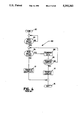
- FIG. 5 is a flow chart showing link maintenance according to the present invention.
- FIG. 6 is a flow chart of the basic hand shake procedure
- FIG. 7 is a timing diagram of a successful hand shake
- FIG. 8 is a block diagram of the transmitter base band circuitry
- FIG. 9 is a flow chart for establishing link availability of the transmitter channel
- FIG. 10 is a block diagram showing the analog modulation circuitry
- FIG. 11 is a block diagram of the digital modulation circuitry
- FIG. 12 is a schematic diagram of the transmitter rf circuitry
- FIG. 13 is a block diagram of the receiver circuitry
- FIG. 14 is a block diagram of the cyclic redundancy code circuitry
- FIG. 15 is a detailed schematic diagram of the up link CRC control circuitry
- FIG. 16 is a schematic diagram of the CRC parser
- FIG. 17 is a schematic diagram of the overall CRC control circuit.
- FIG. 18 is a detailed schematic diagram of the CRC calculation circuitry.
- FIG. 1 is a simplified schematic diagram of the present invention as employed in a communication link between an external programmer and an implanted cardiac pacer.
- An implantable pulse generation 10 is implanted in the patient under the outer skin barrier 28.
- Implantable pulse generator 10 is electrically coupled to the heart of the patient using at least one cardiac pacing lead 12 in a manner known in the art.
- Percutaneous telemetry data is transmitted from implantable pulse generator 10 by an RF up link 26 utilizing the improved telemetry format to a receiving antenna 22, which is coupled to a programmer 20 via a cable 24.
- Receiving antenna 22 also contains a magnet which activates a reed switch in implantable pulse generator 10 as a safety feature, as taught in U.S. Pat. No. 4,006,086 issued to Alferness et al., herein incorporated by reference.
- the telemetry data is demodulated and presented to the attending medical personnel by programmer 20.
- programmer 20 transmits signals via radio frequency energy sent from antenna 22 under control of signals transferred from programmer 20 along cable 24. This energy reaches implantable pulse generator 10 by down link 27. The transmitted signals are utilized by implantable pulse generator 10 after demodulation.
- indicator 25 provides notification to the operator of the link that a disruption has occurred.
- indicator 25 is a light emitting diode, LED.
- the LED is illuminated whenever a periodically scheduled (i.e. approximately every 250 milliseconds) handshake has been unsuccessful.
- the operator Upon seeing indicator 25 illuminated, the operator is instructed to reposition antenna 22 slightly to improve reception along the link. Failure to properly reposition antenna 22 for five seconds (i.e. 20 unsuccessful hand shake attempts) causes the link to be terminated.
- the operator is so notified by programmer 20 using standard techniques. The hand shake protocol is explained in more detail below.
- FIG. 2 is a schematic diagram of the protocol utilized by RF up link 26. These links use a damped 175 kilohertz RF carrier which is phase shift modulated for analog data and pulse position modulated for digital (or digitized) data, as described in detail below. Shown at 30, the basic timing unit of the format is a frame, having a duration of t n5 . It will be understood by those skilled in the art, however, that the present invention can be practiced using fixed-length frames having periods of shorter or longer duration.
- the main timing source of implantable pulse generator 10 comprises a standard 32.768 kilohertz crystal clock which provides a basic clock cycle of 30.52 microseconds.
- a frame comprised of 64 clock cycles and extending over a fixed time interval of 1.953125 milliseconds a convenient frame period, since such frame period is a binary multiple of the basic clock cycle.
- a unique synchronizing signal is positioned within a first fixed range of each frame 30.
- This signal comprises a synchronizing RF pulse 32 which is located a time t n1 within frame 30. To properly function as a synchronizing pulse, it must be located at a fixed point within the first fixed range of frame 30, as shown at 34.
- a four-bit frame identifier code is positioned within a second fixed range of each frame 30, such second fixed range comprising an identifier range 38.
- Identifier range 38 uses a total of eleven basic clock cycles as shown.
- This identifier code comprises an identifier RF pulse 36 which is pulse position modulated within the identifier range 38.
- the position of identifier pulse 36 within identifier range 38 identifies the nature or type of data found within each frame 30 which is being transmitted, such as peak sense, peak pressure, sense threshold and others, as described in further detail below.
- time interval t n2 thus uniquely represents the value of identifier pulse 36, which value in turn identifies the data type being transmitted within frame 30.
- one unique frame identifier code is a hand shake request employed within the hand shake protocol to maintain the link communication.
- Each frame 30 transfers one eight-bit byte of digital data along with the identifier code.
- This data is divided into two portions comprised of four bits of data each.
- a first portion of this data namely the four least significant bits of the data byte, is positioned within a third fixed range of frame 30, such third fixed range comprising a lower nibble range 44.
- a second portion of this data namely the four most significant bits of the data byte, is positioned within a fourth fixed range of frame 30, such fourth fixed range comprising an upper nibble range 48.
- a lower nibble pulse 42 is pulse position modulated within lower nibble range 44, such that its value is uniquely identified by its location, such as at a time t n3 shown at 45.
- An upper nibble pulse 46 is also pulse position modulated within upper nibble range 48, such that its value is uniquely identified by its location, such as at a time t nr shown at 50.
- Lower nibble range 44 and upper nibble range 48 each comprise sixteen basic clock cycles, permitting each of the sixteen unique values of the four-bit nibble to be specified.
- suitable guard bands are positioned between each of the ranges within the frame to uniquely identify the synchronizing pulses, thereby avoiding undefined and erroneous data transmission.
- identifier pulse 36, lower nibble pulse 42, and upper nibble pulse 46 are phase shift modulated with analog data in addition to being pulse position modulated with digital information.
- the pulse position within the frame is used along with the instantaneous analog signal value to define the instantaneous phase of the carrier.
- Synchronizing RF pulse 32 has a fixed phase as well as a fixed pulse position such that it can conveniently serve as a phase standard for analog demodulation as well as a time standard for digital demodulation.
- FIG. 3 is a diagram of two frames of transmission from either RF up link 26 or down link 27, wherein a first frame corresponds to Word 1 shown at 70, and a second frame corresponds to Word 2 shown at 72.
- a count of clock cycles is indicated along an upper horizontal axis of this diagram for each frame. Each basic clock cycle has a duration of 30.52 microseconds.
- the first frame at 70 is initiated by an RF pulse 52.
- a synchronizing RF pulse 54 is shown uniquely identified as precisely four clock cycles later. Because the guard bands are all greater than four clock cycles, no combination of a frame identifier and data can appear as a synchronizing pulse. Synchronizing pulse 54 is used to provide frame synchronization between the transmitter and the receiver.
- An identifier RF pulse 56 is located within identifier range 38, defined as nine to nineteen basic clock cycles from the beginning of frame 70. In Word 1, for example, identifier pulse 56 is located at clock cycle nineteen. For RF up link 26, this identifies the frame as a particular type of data transfer, namely, "Sense Threshold" as indicated in Table 1 below.
- a lower nibble RF pulse 58 is located within lower nibble range 44, which range is defined as twenty-four to thirty-nine basic clock cycles from the beginning of frame 70.
- lower nibble pulse 58 is located at clock cycle thirty-one, specifying a decimal value of seven on a scale of zero to fifteen.
- An upper nibble RF pulse 60 is located at clock cycle fifty-eight within upper nibble range 48, which range is defined as forty-four to fifty-nine basic clock cycles from the beginning of frame 70, and is demodulated in similar fashion.
- RF pulses 56, 58, and 60 can be phase shift modulated with analog data as well.
- RF pulses 52 and 54 have a constant phase and thus serve as a phase standard for analog demodulation.
- FIG. 4 is a flow chart 100 for the common prior art method of maintaining the transmission link.
- the basis of this technique is a magnet located within the housing of antenna 22 (see also FIG. 1). This housing is often called an RF head within the art. Presence of the magnetic field generated by this magnet closes a reed switch within implantable pulse generator 10 if in sufficiently close proximity.
- the hardware details of this approach are provided in the above identified and incorporated U.S. patent to Alferness et al.
- the technique is started at element 102.
- the RF head is manually positioned by the attending medical personnel at element 105.
- Element 103 determines whether the magnet within the RF head has in fact closed the reed switch within implantable pulse generator 10. If element 107 extinguishes the LED indicator, the operator is notified that the RF head position is satisfactory.
- element 104 permits further data transfer via element 112 as long as the reed switch within implantable pulse generator 10 remains closed. If the reed switch opens before the transfer is completed, element 110 records a failure to complete the transmission. If the transfer has been completed, however, as determined by element 108, element 114 provides a normal exit.
- the reed switch must be closed and remain closed for the entire duration of the transmission to be deemed satisfactory.
- incomplete transfers become more prevalent because of patient movement, inadvertent movement of antenna 22, and other practical difficulties.
- FIG. 5 is a flow chart 116 of the method of maintaining the link according to the preferred mode of the present invention.
- the link protocol is entered at element 118.
- the RF head is manually positioned at element 119 and checked by element 120, which causes initiation of the link upon the closing of the reed switch.
- the link may be maintained without continuous closing of the reed switch as will become apparent.
- element 122 causes implantable pulse generator 10 to commence sending the marker channel timing signals which are well known in the art to programmer 20.
- the basic hand shake procedure is performed at element 124. This procedure is described in more detail below. If a reply was not received by the requesting device during the hand shake procedure, element 126 routes control to element 128 to determine whether a time out has occurred. Time out is defined as a five second period of time during which no hand shake procedure has been successful. In the preferred mode, the hand shake procedure is executed every 250 milliseconds, which means that time out corresponds to 20 consecutive unsuccessful hand shake procedures. If a time out has occurred, element 130 records an incomplete transfer and exit is obtained via element 132. If a time out has not occurred, element 129 increments the time out counter indicating that another unsuccessful consecutive hand shake procedure has been experienced and returns control to element 136 for data transfer.
- element 134 Whenever element 126 determines that the hand shake procedure has been successful, element 134 rests the session time out timer. This corresponds to a break in the chain of unsuccessful hand shake procedures if any. After the reset, the link will not time out for at least five more seconds.
- Element 138 determines whether the current data transfer is complete. This may be defined within the data stream itself. If yes, element 140 records a successfully completed data transfer and exit occurs via element 144. If the entire data transfer is not yet complete, element 142 determines whether it is time for another hand shake procedure. A new hand shake procedure is scheduled every 250 milliseconds. The resultant time interval between hand shake procedures (requiring two frames) corresponds to 124 data frames which consume about 248 milliseconds.
- control is returned to element 136 for additional data transfer. If the 250 milliseconds has elapsed, however, control is given to element 124 to schedule another hand shake procedure.
- the link can maintained without continuous closure of the reed switch.
- forward error detection techniques along with retransmission of incorrect data blocks, as described below, the link can be efficiently maintained even though actual data transmission continuity is temporarily interrupted.
- FIG. 6 is a flow chart 146 of the hand shake procedure. Upon being called, entry is via element 148. In the preferred mode, implantable pulse generator 10 transmits the hand shake request at element 150. However, those of skill in the art will readily appreciate that the hand shake request could also be transmitted from programmer 20.
- the transmitted hand shake request is a frame having a unique frame identifier (see above) without any data pulses (as shown below).
- element 155 transfers control to element 158 to record a hand shake failure and exit the procedure at element 160.
- Element 154 determines whether implantable pulse generator 10 has received the reply.
- Element 156 illustrates that some tens of microseconds are expended awaiting the reply. If none is received in time, element 158 records the hand shake failure and exits via element 160.
- a properly timed reply received by implantable pulse generator 10 causes transmission of a confirmation signal as shown at element 162.
- Element 164 causes element 166 to extinguish indicator 25 if programmer 20 receives the confirmation and to illuminate indicator 25 if programmer 20 does not receive the confirmation. Exit is via element 170.
- FIG. 7 is a timing diagram showing the two frame couplet associated with the hand shake procedure.
- the lower time line comprising request frame 190 and confirmation frame 192 shows that the total transmission time for a successful hand shake is two frames or approximately four milliseconds.
- the hand shake requestor is implantable pulse generator 10, although those of skill in the art can readily appreciate that this function could also be assigned to programmer 20.
- Implantable pulse generator transmits a standard frame initiation pulse at 176 and frame synchronizing pulse 178 (see also FIG. 2).
- the frame identification pulse 180 is chosen to uniquely identify this as a hand shake request (see also Table 1 above).
- Frame identification pulse 180 is placed within the frame identification range as with other frame identifiers (see also FIGS. 2 and 3).
- Time window 182 is the time relative to the frame synchronizing pulse (i.e. pulse 178) during which the implantable pulse generator must receive a hand shake reply to achieve a successful hand shake.
- Time window 182 corresponds to the time during which the lower nibble and upper nibble of data would ordinarily be transmitted (see also FIG. 2).
- the frame for programmer 20 begins at point 172. If it has received and properly decoded frame identification pulse 180 as a hand shake request, it transmits hand shake reply pulse 174 as shown.
- implantable pulse generator 10 If implantable pulse generator 10 receives and properly decodes hand shake reply pulse 174 during time window 182, it transmits confirmation pulses 186 and 188 during the next succeeding frame which begins at point 184 and is defined by frame synch pulse 185 and frame identifier pulse 187. Note that the hand shake has been successful to implantable pulse generator 10 if it receives hand shake reply pulse 174 during the first frame. However, programmer 20 must wait until receipt of confirmation pulses 186 and 188 during the second frame to record a successful hand shake.
- this particular handshake technique which uses the standard frame size and protocol, periodically ensures that synchronization between programmer 20 and implantable pulse generator 10 is maintained throughout the entire transmission. Furthermore, no data is lost following confirmation due to the need to re-synchronize.
- FIG. 8 is a block diagram of that portion of implantable pulse generator 10 which is associated with formatting and transmission of RF up link 26.
- Most of the unique hardware which embodies the present invention is located on a single substrate, including custom hybridized circuitry indicated generally by arrow 105.
- the remainder of the hardware, which is preferably located on the same substrate, is microprocessor-based logic indicated generally by arrow 100, comprising microprocessor 102, random access memory (RAM) 104, and parallel bus 106.
- RAM random access memory
- Hybrid circuit 105 has an analog-to-digital (A/D) converter 108 which receives a number of analog inputs 110 from a multiplexer (not shown). A/D converter 108 permits data to be transferred via RF up link 26 to be digitized as necessary. The same data may also be transmitted in analog form as discussed further below. Circuitry (CRC) for generating and analyzing the cyclic redundancy code used to forward error detect telemetry data transmitted over RF up link 26 is indicated at 112. The structure and operation of CRC 112 is also discussed in greater detail below. Because of the forward error detection technique chosen for the preferred embodiment, CRC 112 is also used for data received by implantable pulse generator 10 via down link 27.
- Circuitry (DMA) for providing direct memory access to RAM 104 is indicated at 114, thus permitting multiple byte transfers without constant management by microprocessor 102.
- Key hardware used to implement RF up link 26 comprises telemetry control and data buffer circuitry indicated generally within dashed lines at 121, which circuitry includes data buffer 116 and telemetry control 120, and up-link timing circuitry 118.
- Data buffer 116 includes storage for twelve bits of data. This storage is partitioned into a four-bit section 119 for storage of the frame identifier code, and an eight-bit section 117 for storage of the lower nibble and upper nibble of a frame. Data buffer 116 thus stores all of the variables for one complete frame. Data buffer 116 is used to stage the variables for the frame Which may be received from RAM 104, A/D converter 108, CRC 112, or elsewhere along parallel bus 106.
- Telemetry control 120 consists primarily of a telemetry status register. This register stores the telemetry commands and status as loaded by microprocessor 102. The contents of the register are thus used to gate the data at the proper time of the defined protocol.
- Up-link timing 118 decodes the twelve bits of data stored in data buffer 116 to produce a set of timing signals which key bursts of RF energy at the appropriate times to pulse position modulate the 175 kilohertz carrier. Up-link timing 118 also keys bursts of RF energy at the fixed positions within the frame corresponding to the frame-initiating pulse and the synchronizing pulse.
- Analog inputs 110 are also presented to analog switch 111, which serves as a simple analog multiplexer.
- the particular analog signal to be selected for transmission on the analog channel is determined by control bus 109 which similarly selects the desired analog input for the digital channel.
- the analog signal selected by analog switch 111 is transferred via line 113 to the modulation hardware. The instantaneous analog value on this line will determine the instantaneous phase of the modulated bursts of carrier energy even as the output of link timing 118 determines the pulse position of those same bursts.
- FIG. 9 is a basic flow chart showing the overall scheduling function of the microprocessor-based logic 100. The role is essentially one of initiation of the transfer, rather than management of each detail of the transmission.
- Software associated with RF up link 26 is started at element 130, usually by the initial reed switch closure (see also FIG. 5).
- Element 132 schedules the requested transmission via the up-link facilities. This scheduling prioritizes up link transmission requests. Lower priority is given to continuous real time transfers, such as EGM and battery voltage, whereas higher priority is given to single occurrence transmissions of status information. Also considered is the internal timing of the cardiac pacer functions. It has been determined through experience that the most reliable results are obtained when the up-link transmission occurs between paced QRS events. Therefore, it is desirable to schedule up-link transmissions to be initiated after the conclusion of a QRS event and to be concluded before the beginning of the next QRS event.
- element 134 determines whether an up link transmission is currently in progress. If an up link transmission is in progress, element 132 reschedules the request.
- element 136 initiates the up link transmission by activating telemetry control 120. Exit is via element 138. While some additional management of the process is required during the transmission, a description of such further details has been omitted, since it is not believed necessary to one skilled in the art to fully understand the present invention.
- Appendix A a source code listing of the pertinent sections of such software has been attached hereto as Appendix A, and is incorporated by reference herein.
- FIG. 10 is a block diagram showing the modulation circuitry. It includes major data and control elements of telemetry control and data buffer 121 (which includes data buffer 116 and telemetry control 120 shown in FIG. 8), and also of up-link timing 118 which provide the digital modulation. The remaining elements shown provide the analog channel modulation.
- a primary function of data buffer 116 is the staging of the twelve variable bits of a given frame which correspond to a four-bit frame identifier ID, and dual-nibble data comprising a four-bit lower nibble LN and a four-bit upper nibble UN.
- the data is received over an eight-bit, parallel bus 159 and can be from any one of several sources.
- Control lines EGMDATA at 150, PRSDATA at 151, DLDMA at 153, DMADS at 155, LDANDAT at 156, ENCRC at 161 and LDCRC at 171 specify the source.
- the output of A/D converter 108 of FIG. 8 is presented separately to data buffer 116 as an eight-bit parallel transfer to ACD(0-7) at 154 (see also FIG. 11).
- the output of CRC 112 is presented separately to data buffer 116 to CRC(0-15) at 160, since those devices are located on the same substrate.
- Telemetry control 120 outputs a number of control signals, including EGMGAIN at 162, RVPGAIN at 163, EGMTELEN at 164, ANULON at 165, RAMULON at 166, MEMEN at 167, PRSTELEN at 168, HDRCRCEN at 169 and EGMNPRS at 170. These control outputs are used to enable and control inputs to data buffer 116.
- the key outputs of telemetry control and data buffer 121 are TELRST at 182, which resets up-link timing and initiates the beginning of a frame, and a parallel data transfer at 184, which transfers the frame identifier ID, lower nibble LN and upper nibble UN to up-link timing 118.
- Up-link timing 118 receives the frame-initiating control signal TELRST at 182 and the parallel data transfer (ID, LN and UN) at 184.
- a primary function of up-link timing 118 is to key the transmission of 175 kilohertz RF energy at the proper times to indicate start of frame, frame, frame synchronization, frame identifier, lower nibble and upper nibble.
- Timing for the radio frequency carrier generation is provided by the 32.768 kilohertz crystal oscillator 179. Its output is provided to phase shift modulator 181 which varies the phase in response to the analog signal present on line 113. Because the 32.768 kilohertz signal is being phase modulated, the modulation pass band of phase shift modulator 181 is about thirty times that of the effective pass band of the analog transmission channel which is limited by the number of modulated carrier bursts (i.e. three) per two millisecond frame.
- RF switch 185 is a double throw switch which switches between the phase shift modulated signal received from phase shift modulator 181 and the unmodulated signal received directly from crystal oscillator 179.
- the switch operates in response to the state of input line 183 which indicates whether or not a frame synchronizing pulse is to transmitted. If yes, RF switch provides the unmodulated output of crystal oscillator 179 to the oscillator input of up-link timing 118 via line 186. This means that frame synchronizing bursts will have a constant phase and may therefore be utilized by the receiver as a phase standard to prevent long term phase drift.
- RF switch 185 provides link timing 118 with a 32.768 kilohertz signal via line 186 which has been phase shift modulated with the selected analog data.
- FIG. 11 is a block diagram of up-link timing 118.
- a frame timing generator 202 provides the desired timing for a frame according to clock input OSC. at 186, in a manner herein above explained.
- each frame is comprised of sixty-four basic clock cycles. The process is initiated by receipt of the frame-initiating control signal TELRST at 182, which enables up link when in a low state and disables up link when in a high state.
- the initial clock cycle of a frame contains a burst of RF energy which is keyed by control signal TELCLK at 188, which is also used to trigger the start of the data decoding by an up link word multiplexer 200.
- a telemetry pulse timer 204 determines the appropriate timing for a burst to be provided to frame timing generator 202, and a corresponding burst of RF energy is keyed. Each of the four-bit quantities thus results in the keying of a burst of RF energy at the appropriate time within each frame.
- FIG. 12 is a circuit diagram for the drive circuit for generating the RF carrier.
- a control signal TELCLK at 188 provides the timing information for keying the carrier.
- a non-overlap generator 220 functions as a delay device to save current by preventing output transistors 230 and 232 from conducting simultaneously. Every transition of control signal TELCLK at 188 causes one transition by non-overlap generator 220.
- Inverters 222, 224, 226 and 228 are scaled to provide efficient switching with sufficient drive to the gates of transistors 230 and 232.
- Transistors 230 and 232 drive the signal off of chip 105 to ANTDR at 234 to an antenna circuit.
- a tuned circuit of discreet components, capacitor 236 and coil 238, are located external to chip 105. Each transition thus causes this tuned circuit to resonate at 175 kilohertz, thereby generating one up link burst.
- FIG. 13 is a block diagram of the receiver circuit 300 for demodulating both analog and digital channels.
- the radio frequency energy is received by antenna 302.
- antenna 302 is the functional equivalent of the physical antenna 22 (see also FIG. 1).
- the radio frequency energy is amplified by rf amplifier 304 and provided to filter 306 to select the desired pass band (i.e. narrowly tuned about the 175 kilohertz carrier).
- the amplified and filtered radio frequency data is provided by cable 314 to digital demodulator 318 for conversion to the base band digital data stream output on cable 332.
- the amplified and filtered radio frequency energy is also provided to rf switch 310 which is a simple double throw switch. Whenever a digital synchronizing pulse is present at digital demodulator 318, line 320 cause rf switch 310 to route the radio frequency energy received on cable 314 to phase lock loop 312 via cable 334. In this way the constant phase synchronizing pulses are utilized by the receiver as a phase standard for the internal 175 kilohertz oscillator 308.
- the phase corrected internal standard is provided to phase shift demodulator 328 via cable 322.
- line 320 causes rf switch 310 to switch the radio frequency energy received on cable 314 to integrator 324 via cable 316.
- the radio frequency stream sent to phase shift demodulator 328 via cable 326 appears to be a continuous 175 kilohertz carrier which has been phase shift modulated using a relatively low frequency (i.e. less than 200 hertz) analog base band signal.
- Phase shift demodulator 328 demodulates the 175 kilohertz signal received via cable 326 using the internal 175 kilohertz phase standard received via cable 322 in accordance with known techniques.
- the analog output on line 330 is typically an EGM or other relatively low frequency analog signal.
- FIG. 14 is an overall block diagram of cyclic redundancy circuit, CRC 112. The importance of this circuit is that it provides forward error detection in a highly efficient manner using a minimum of redundant transmission band width. This becomes a significant feature for transcutaneous data links wherein total data transmission requirements are relatively large.
- Forward error detection is provided by using the transmission data as coefficients of a polynomial.
- this polynomial is divided (in modulo 2 arithmetic, i.e. no carry/borrow function) by a generator polynomial, the remainder is the cyclic redundancy code which is transmitted as 16 redundant bits appended to the end of the transmitted data block.
- the receiving device utilizes the received data, along with the cyclic redundancy code to generate a new polynomial. If division by the same generator polynomial results in a zero remainder, the transmission is assumed to have been error free.
- hardware has been used to perform these functions although those of skill in the art can appreciate that software implementation is also feasible.
- the CRC 112 comprises four principle circuits.
- the up link controller 400 provides timing signals for generation and insertion of the cyclic redundancy codes.
- the parser 402 serializes the incoming transmission data.
- Control 404 sets up the calculation process, and calculator 406 produces the actual 16 bit cyclic redundancy code, as two eight bit words. Note that except for interpretation of the result, receipt and processing of the received cyclic redundancy codes is nearly identical and is accomplished with the same hardware elements.
- FIG. 15 is a detailed schematic diagram of the up link controller 400.
- the basic crystal timing standard is received via line 434. This signal times the output on line 420 of the up link shift signal held by flip flop 458, which clocks parser 402 as explained below.
- Flip flops 460, 462, 464, and 466 clear flip flop 458 after an appropriate delay.
- Flip flop 458 is clocked by the up link DMA reply (i.e. data is available on the data bus) received via line 436 and the header enable received via line 438. Resetting of these flip flops is enabled by the signal received via line 440.
- the up link load and up link shift timing signals basically control timing of the operation of parser 402.
- Control of insertion of the cyclic redundancy code into the transmitted data stream is achieved using the CRC second byte signal on line 424, the enable CRC signal on line 426, the load CRC signal on line 428, the sum signal on line 430, and the telemetry interrupt signal on line 432 (see also FIG. 14). These signals are generated as shown using DMS data synch signal on line 444, the zero signal on line 446, the memory enable signal on line 448, the header timing signal on line 450, the frame place signal on line 452, and the synch place signal on line 454 (see also FIG. 11).
- FIG. 16 is a schematic diagram of parser 402.
- the eight transmission data bits are received via cable 414. Each is loaded into the corresponding one of the flip flops 484, 486, 488, 490, 492, 494, 496, and 498, respectively. Loading is enabled by the up link load signal received on line 500 (see also FIG. 15) with inverter 480 providing the corresponding opposite load signal for each flip flop.
- the data After loading of an eight bit byte into the eight bit register, the data is clocked serially from one bit position to the next to serialize the data. Clocking of this shift function which serializes the data is provided by the up link shift signal received on line 502 and invertor 482. The resulting bit stream is output on line 416.
- FIG. 17 is a schematic diagram of control circuit 404 which controls the CRC calculation process.
- the delayed clock signal received on line 528 is used to switch the CRC data in signal of line 526 alternately between the serialized up-link data received via line 416 and the down-link data received on line 540.
- the outputs on lines 522 and 524 correspond to the CRC clock signal and the inverted CRC clock signal. This is produced by alternately switching between the up link shift signal received via line 536 and the synch clock signal received via line 538. This switching is accomplished at the same rate as the switching which produces the CRC data in signal. However, the latter is generally delayed by one more inverter level before being placed on line 526.
- the CRC reset signal which is placed on line 520 is produced by the not output of flip flop 542 as enabled by the header enable, down-link signal or fourth delay of the crystal output.
- Flip flop 542 is reset by the fourth delay of the crystal output.
- FIG. 17 is a detailed schematic diagram of CRC calculation circuitry 406.
- the outputs of this circuit are the 16 bit up-link cyclic redundancy code for transmitted data transferred via bus 408, and the corresponding down-link CRC zero check for received data, which is output on line 410.
- the serialized data to be transmitted is presented to exclusive or 550 by line 526 (see also FIG. 17).
- This serialized bit stream is presented to flip flops 552, 554, 556, 558, 560, 562, 564, 566, 568, 570, 572, 574, 576, 578, 580, and 582.
- These devices provide a CRC shift register which is a single 16-bit shift register with mod 2 sum feedback. This effectively implements the modulo 2 division resulting in a 16 bit remainder.
- the CRC second byte signal is used to stage the two bytes of the 16-bit remainder, appending the CRC to the up-linked data stream.
- the received data is clocked into the flip flops by the CRC clock signal received via line 524.
- Each flip flop is reset by the CRC reset signal presented on line 520.
- the zero check signal presented on line 410 is produced by flip flop 584, if no error is present in the received data.
Abstract
Description
TABLE 1 ______________________________________ (Up link Frame Identifiers) Position Identification ______________________________________ 9Memory 10 Hand shake request 11 EGM-1 12 Markers 13 Peak Sense 14Pressure Waveform 15 Peak dp/dt 16Peak Pressure 17 Delta Capacitor Voltage 18Activity Counts 19 Sense Threshold ______________________________________
Claims (3)
Priority Applications (1)
| Application Number | Priority Date | Filing Date | Title |
|---|---|---|---|
| US07/896,645 US5292343A (en) | 1990-01-22 | 1992-06-10 | Hand shake for implanted medical device telemetry |
Applications Claiming Priority (3)
| Application Number | Priority Date | Filing Date | Title |
|---|---|---|---|
| US46840790A | 1990-01-22 | 1990-01-22 | |
| US07/765,475 US5127404A (en) | 1990-01-22 | 1991-09-25 | Telemetry format for implanted medical device |
| US07/896,645 US5292343A (en) | 1990-01-22 | 1992-06-10 | Hand shake for implanted medical device telemetry |
Related Parent Applications (1)
| Application Number | Title | Priority Date | Filing Date |
|---|---|---|---|
| US07/765,475 Continuation-In-Part US5127404A (en) | 1990-01-22 | 1991-09-25 | Telemetry format for implanted medical device |
Publications (1)
| Publication Number | Publication Date |
|---|---|
| US5292343A true US5292343A (en) | 1994-03-08 |
Family
ID=27042382
Family Applications (4)
| Application Number | Title | Priority Date | Filing Date |
|---|---|---|---|
| US07/765,475 Expired - Lifetime US5127404A (en) | 1990-01-22 | 1991-09-25 | Telemetry format for implanted medical device |
| US07/896,641 Expired - Lifetime US5314450A (en) | 1990-01-22 | 1992-06-10 | Dual channel telemetry for implanted medical device |
| US07/896,645 Expired - Lifetime US5292343A (en) | 1990-01-22 | 1992-06-10 | Hand shake for implanted medical device telemetry |
| US07/944,872 Expired - Lifetime US5344431A (en) | 1990-01-22 | 1992-09-14 | Method and apparatus for determination of end-of-service for implantable devices |
Family Applications Before (2)
| Application Number | Title | Priority Date | Filing Date |
|---|---|---|---|
| US07/765,475 Expired - Lifetime US5127404A (en) | 1990-01-22 | 1991-09-25 | Telemetry format for implanted medical device |
| US07/896,641 Expired - Lifetime US5314450A (en) | 1990-01-22 | 1992-06-10 | Dual channel telemetry for implanted medical device |
Family Applications After (1)
| Application Number | Title | Priority Date | Filing Date |
|---|---|---|---|
| US07/944,872 Expired - Lifetime US5344431A (en) | 1990-01-22 | 1992-09-14 | Method and apparatus for determination of end-of-service for implantable devices |
Country Status (1)
| Country | Link |
|---|---|
| US (4) | US5127404A (en) |
Cited By (122)
| Publication number | Priority date | Publication date | Assignee | Title |
|---|---|---|---|---|
| US5562713A (en) * | 1995-01-18 | 1996-10-08 | Pacesetter, Inc. | Bidirectional telemetry apparatus and method for implantable device |
| US5752977A (en) * | 1997-04-15 | 1998-05-19 | Medtronic, Inc. | Efficient high data rate telemetry format for implanted medical device |
| WO1998025669A1 (en) | 1996-12-13 | 1998-06-18 | Medtronic, Inc. | Method and apparatus for diagnosis and treatment of arrhythmias |
| WO1998033554A1 (en) | 1997-01-31 | 1998-08-06 | Medtronic, Inc. | Implantable impedance measurement system |
| WO1998033553A1 (en) | 1997-01-31 | 1998-08-06 | Medtronic, Inc. | Impedance respiratory rate measuring edema monitor |
| US5836975A (en) * | 1996-12-19 | 1998-11-17 | Medtronic, Inc. | Method and apparatus for diagnosis and treatment of arrhythmias |
| US5861019A (en) * | 1997-07-25 | 1999-01-19 | Medtronic Inc. | Implantable medical device microstrip telemetry antenna |
| US5987356A (en) * | 1997-06-05 | 1999-11-16 | Medtronic, Inc. | Method and apparatus for diagnosis and treatment of arrhythmias |
| US6009350A (en) * | 1998-02-06 | 1999-12-28 | Medtronic, Inc. | Implant device telemetry antenna |
| EP1018217A1 (en) * | 1997-09-08 | 2000-07-12 | Tut Systems, Inc. | Method and apparatus for encoding and decoding a bit sequence for transmission over pots wiring |
| US6163721A (en) * | 1998-04-29 | 2000-12-19 | Medtronic, Inc. | Power consumption reduction in medical devices by employing pipeline architecture |
| US6167310A (en) * | 1999-03-31 | 2000-12-26 | Medtronic, Inc. | Downlink telemetry system and method for implantable medical device |
| US6167303A (en) * | 1998-04-29 | 2000-12-26 | Medtronic, Inc. | Power consumption reduction in medical devices employing just-in-time clock |
| DE19930263A1 (en) * | 1999-06-25 | 2000-12-28 | Biotronik Mess & Therapieg | Method and device for data transmission between an electromedical implant and an external device |
| US6185454B1 (en) | 1998-04-29 | 2001-02-06 | Medtronic, Inc. | Power consumption reduction in medical devices employing just-in-time voltage control |
| US6200265B1 (en) | 1999-04-16 | 2001-03-13 | Medtronic, Inc. | Peripheral memory patch and access method for use with an implantable medical device |
| US6201993B1 (en) * | 1998-12-09 | 2001-03-13 | Medtronic, Inc. | Medical device telemetry receiver having improved noise discrimination |
| US6223083B1 (en) | 1999-04-16 | 2001-04-24 | Medtronic, Inc. | Receiver employing digital filtering for use with an implantable medical device |
| WO2001032261A1 (en) * | 1999-10-29 | 2001-05-10 | Medtronic, Inc. | Tactile feedback for indicating validity of communication link with an implantable medical device |
| US6285909B1 (en) | 1999-05-27 | 2001-09-04 | Cardiac Pacemakers, Inc. | Preserving patient specific data in implantable pulse generator systems |
| US6295473B1 (en) | 1999-04-16 | 2001-09-25 | Medtronic, Inc. | Digital delay line receiver for use with an implantable medical device |
| US6317626B1 (en) | 1999-11-03 | 2001-11-13 | Medtronic, Inc. | Method and apparatus for monitoring heart rate |
| US6332094B1 (en) | 1993-03-19 | 2001-12-18 | Peter Gregory Gorman | Personal monitor and method using identification to minimize interference |
| US6434429B1 (en) | 1999-06-25 | 2002-08-13 | Biotronik Mess- Und Therapiegeraete Gmbh & Co. Ingenieurbuero Berlin | Implant with close and long-range telemetry |
| US20020109621A1 (en) * | 2000-04-18 | 2002-08-15 | Motorola, Inc. | Wireless system protocol for telemetry monitoring |
| US6438407B1 (en) | 2000-03-20 | 2002-08-20 | Medtronic, Inc. | Method and apparatus for monitoring physiologic parameters conjunction with a treatment |
| US6470215B1 (en) | 1999-06-25 | 2002-10-22 | Biotronik Mess-Und Therapiegeraete Gmbh & Co Ingenieurbuero Berlin | Method of data transmission in implant monitoring |
| US20020161328A1 (en) * | 2001-03-16 | 2002-10-31 | Medtronic, Inc. | Implantable therapeutic substance infusion device with active longevity projection |
| US6490487B1 (en) | 1999-06-25 | 2002-12-03 | Biotronki Mess - Und Therapiegeraete Gmbh & Co. Ingenieurbuero Berlin | Transmitter of the telemetry device of an implant |
| US6508771B1 (en) | 1999-03-05 | 2003-01-21 | Medtronic, Inc. | Method and apparatus for monitoring heart rate |
| US6512949B1 (en) | 1999-07-12 | 2003-01-28 | Medtronic, Inc. | Implantable medical device for measuring time varying physiologic conditions especially edema and for responding thereto |
| US20030040305A1 (en) * | 2000-04-18 | 2003-02-27 | Motorola, Inc. | Programmable wireless electrode system for medical monitoring |
| US6548826B2 (en) | 2000-04-25 | 2003-04-15 | Andreas A. Fenner | Apparatus for wafer-level burn-in and testing of integrated circuits |
| US6574509B1 (en) | 1999-06-25 | 2003-06-03 | Biotronik Mass- Und Therapiegerate Gmbh & Co. Ingenieurbuero Berlin | Apparatus for the transmission of data in particular from an electromedical implant |
| US6577896B2 (en) | 1998-05-07 | 2003-06-10 | Medtronic, Inc. | Single complex electrogram display having a sensing threshold for an implantable medical device |
| US20030114897A1 (en) * | 2001-12-19 | 2003-06-19 | Von Arx Jeffrey A. | Implantable medical device with two or more telemetry systems |
| US20030176906A1 (en) * | 2002-03-15 | 2003-09-18 | Medtronic, Inc | Method and apparatus for connecting various implantable medical treatment system component devices |
| US20030191503A1 (en) * | 2001-07-31 | 2003-10-09 | Cardiac Pacemakers, Inc. | Cardiac rhythm management system for edema |
| US20030199777A1 (en) * | 2000-07-18 | 2003-10-23 | Motorola, Inc. | Wireless electrocardiograph system and method |
| US20040049246A1 (en) * | 2000-06-19 | 2004-03-11 | Medtronic, Inc. | Implantable medical device telemetry processor |
| US6714811B1 (en) | 1999-03-05 | 2004-03-30 | Medtronic, Inc. | Method and apparatus for monitoring heart rate |
| US20040116981A1 (en) * | 2002-12-13 | 2004-06-17 | Cardiac Pacemakers, Inc. | Device communications of an implantable medical device and an external system |
| US6752765B1 (en) | 1999-12-01 | 2004-06-22 | Medtronic, Inc. | Method and apparatus for monitoring heart rate and abnormal respiration |
| US20040122489A1 (en) * | 2002-12-23 | 2004-06-24 | Cardiac Pacemakers, Inc. | Implantable medical device having long-term wireless capabilities |
| US20040122488A1 (en) * | 2002-12-23 | 2004-06-24 | Cardiac Pacemakers, Inc. | Method and apparatus for enabling data communication between an implantable medical device and a patient management system |
| US20040127802A1 (en) * | 2001-07-17 | 2004-07-01 | Gmp Companies, Inc. | Wireless ECG system |
| US20040172080A1 (en) * | 2002-12-04 | 2004-09-02 | Stadler Robert W. | Method and apparatus for detecting change in intrathoracic electrical impedance |
| US6804559B1 (en) | 1999-06-25 | 2004-10-12 | Biotronik Mess -Und Therapiegeraete Gmbh & Co. Ingenieurbuero Berlin | Electromedical implant |
| US6820019B1 (en) | 1999-07-31 | 2004-11-16 | Medtronic, Inc. | Device and method for determining and communicating the remaining life of a battery in an implantable neurological tissue stimulating device |
| US20040230233A1 (en) * | 2003-05-13 | 2004-11-18 | Gunderson Bruce D. | Identification of oversensing using sinus R-wave template |
| WO2004112897A1 (en) | 2003-06-19 | 2004-12-29 | Medtronic, Inc. | Method and apparatus for temporarily varying a parameter in an implantable medical device |
| US20050021098A1 (en) * | 2001-07-27 | 2005-01-27 | Cardiac Pacemakers, Inc. | Method and system for treatment of neurocardiogenic syncope |
| US6901293B2 (en) | 2003-04-07 | 2005-05-31 | Medtronic, Inc. | System and method for monitoring power source longevity of an implantable medical device |
| US20050124900A1 (en) * | 2003-12-03 | 2005-06-09 | Stadler Robert W. | Method and apparatus for detecting change in physiologic parameters |
| US20050137639A1 (en) * | 2003-12-23 | 2005-06-23 | Havel William J. | Method and apparatus for actively determining a coupling interval corresponding to a cardiac vulnerable zone |
| US6912420B2 (en) | 2001-04-10 | 2005-06-28 | Cardiac Pacemakers, Inc. | Cardiac rhythm management system for hypotension |
| US20050177206A1 (en) * | 2003-02-21 | 2005-08-11 | North Richard B. | Implantable neurostimulator programming with battery longevity indication |
| US6947795B2 (en) | 2001-10-01 | 2005-09-20 | Transoma Medical, Inc. | Frame length modulation and pulse position modulation for telemetry of analog and digital data |
| US6978182B2 (en) | 2002-12-27 | 2005-12-20 | Cardiac Pacemakers, Inc. | Advanced patient management system including interrogator/transceiver unit |
| US20060025834A1 (en) * | 2002-02-07 | 2006-02-02 | Cardiac Pacemakers, Inc. | Methods and apparatuses for implantable medical device telemetry power management |
| US20060030903A1 (en) * | 2004-08-09 | 2006-02-09 | Michael Seeberger | Dynamic telemetry link selection for an implantable device |
| US20060030902A1 (en) * | 2004-08-09 | 2006-02-09 | Sylvia Quiles | Telemetry switchover state machine with firmware priority control |
| US20060030901A1 (en) * | 2004-08-09 | 2006-02-09 | Sylvia Quiles | Automatic power control for a radio frequency transceiver of an implantable device |
| US20060041280A1 (en) * | 2004-08-19 | 2006-02-23 | Cardiac Pacemakers, Inc. | Thoracic impedance detection with blood resistivity compensation |
| US7009511B2 (en) | 2002-12-17 | 2006-03-07 | Cardiac Pacemakers, Inc. | Repeater device for communications with an implantable medical device |
| US20060089592A1 (en) * | 2004-10-21 | 2006-04-27 | Cardiac Pacemakers, Inc. | Systems and methods for drug therapy enhancement using expected pharmacodynamic models |
| US20060089856A1 (en) * | 2004-10-21 | 2006-04-27 | Cardiac Pacemakers | Integrated pharmaceutical dispensing and patient management monitoring |
| US20060116733A1 (en) * | 2004-12-01 | 2006-06-01 | Gunderson Bruce D | Method and apparatus for identifying lead-related conditions using prediction and detection criteria |
| US20060116732A1 (en) * | 2004-12-01 | 2006-06-01 | Gunderson Bruce D | Method and apparatus for determining oversensing in a medical device |
| US20060116730A1 (en) * | 2004-12-01 | 2006-06-01 | Gunderson Bruce D | Method and apparatus for determining oversensing in a medical device |
| US20060116744A1 (en) * | 2001-12-19 | 2006-06-01 | Cardiac Pacemakers, Inc. | Telemetry duty cycle management system for an implantable medical device |
| US20060161222A1 (en) * | 2005-01-15 | 2006-07-20 | Haubrich Gregory J | Multiple band communications for an implantable medical device |
| US20060293609A1 (en) * | 2005-05-11 | 2006-12-28 | Cardiac Pacemakers, Inc. | Sensitivity and specificity of pulmonary edema detection when using transthoracic impedance |
| US20070011028A1 (en) * | 2005-07-05 | 2007-01-11 | Cardiac Pacemakers, Inc. | Optimization of timing for data collection and analysis in advanced patient management system |
| US20070106130A1 (en) * | 2002-10-09 | 2007-05-10 | Cardiac Pacemakers, Inc. | Detection of congestion from monitoring patient response to a recumbent position |
| US20070156061A1 (en) * | 2005-12-30 | 2007-07-05 | Hess Michael F | Advanced thoracic fluid monitoring capability with impedance |
| US20070260293A1 (en) * | 2006-05-03 | 2007-11-08 | Greg Carpenter | Configurable medical telemetry radio system |
| US20070282398A1 (en) * | 2004-03-15 | 2007-12-06 | Cardiac Pacemakers, Inc. | Cryptographic authentication for telemetry with an implantable medical device |
| US7340296B2 (en) | 2005-05-18 | 2008-03-04 | Cardiac Pacemakers, Inc. | Detection of pleural effusion using transthoracic impedance |
| US20080097545A1 (en) * | 2006-10-20 | 2008-04-24 | Pacesetter, Inc. | Method and Apparatus for Preventing Excessive Power Drain from an Implantable Device |
| US20080215121A1 (en) * | 2004-04-07 | 2008-09-04 | Cardiac Pacemakers, Inc. | System and method for rf wake-up of implantable medical device |
| US20090273349A1 (en) * | 2008-04-30 | 2009-11-05 | Medtronic, Inc. | System and method for monitoring a power source of an implantable medical device |
| US20090299429A1 (en) * | 2008-06-02 | 2009-12-03 | Medtronic, Inc. | Sensing integrity determination based on cardiovascular pressure |
| US20090299432A1 (en) * | 2008-06-02 | 2009-12-03 | Metronic, Inc. | Impedance variability analysis to identify lead-related conditions |
| US20090299201A1 (en) * | 2008-06-02 | 2009-12-03 | Medtronic, Inc. | Electrode lead integrity reports |
| US20090299421A1 (en) * | 2008-06-02 | 2009-12-03 | Medtronic, Inc. | Evaluation of implantable medical device sensing integrity based on evoked signals |
| US20090326600A1 (en) * | 2008-06-30 | 2009-12-31 | Medtronic, Inc. | Lead integrity testing during suspected tachyarrhythmias |
| US20090326599A1 (en) * | 2005-04-26 | 2009-12-31 | John Hatlestad | Calibration of impedance monitoring of respiratory volumes using thoracic d.c. impedance |
| US20100030289A1 (en) * | 2008-07-31 | 2010-02-04 | Medtronic, Inc. | Pre-qualification of an alternate sensing configuration |
| US20100030292A1 (en) * | 2008-07-31 | 2010-02-04 | Medtronic, Inc. | Detecting worsening heart failure based on impedance measurements |
| US20100030293A1 (en) * | 2008-07-31 | 2010-02-04 | Medtronic, Inc. | Using multiple diagnostic parameters for predicting heart failure events |
| US20100045480A1 (en) * | 2005-02-28 | 2010-02-25 | Vineel Vallapureddy | Method and apparatus for antenna selection in a diversity antenna system for communicating with implantable medical device |
| US20100106209A1 (en) * | 2008-10-29 | 2010-04-29 | Medtronic, Inc. | Identification and remediation of oversensed cardiac events using far-field electrograms |
| US20100152562A1 (en) * | 2005-02-08 | 2010-06-17 | Abbott Diabetes Care Inc. | RF Tag on Test Strips, Test Strip Vials and Boxes |
| US20100198097A1 (en) * | 2009-01-30 | 2010-08-05 | Medtronic, Inc. | Detecting worsening heart failure based on fluid accumulation with respiratory confirmation |
| US7818061B1 (en) | 2006-10-13 | 2010-10-19 | Advanced Bionics, Llc | Systems and methods for detecting an error associated with an implantable device |
| US7933642B2 (en) | 2001-07-17 | 2011-04-26 | Rud Istvan | Wireless ECG system |
| US20110105860A1 (en) * | 2009-10-30 | 2011-05-05 | Medtronic, Inc. | Detecting worsening heart failure |
| US20110144526A1 (en) * | 2005-05-11 | 2011-06-16 | Stahmann Jeffrey E | Enhancements to the detection of pulmonary edema when using transthoracic impedance |
| US20110171905A1 (en) * | 2010-01-13 | 2011-07-14 | Roberts Earle T | Proximity based selection of an implantable medical device for far field communication |
| US20110184481A1 (en) * | 2010-01-28 | 2011-07-28 | Medtronic, Inc. | Storage of data for evaluation of lead integrity |
| US8055350B2 (en) | 2005-04-27 | 2011-11-08 | Cardiac Pacemakers, Inc. | System and method for enabling communications with implantable medical devices |
| WO2012058398A1 (en) | 2010-10-29 | 2012-05-03 | Medtronic, Inc. | Method and apparatus for reducing noise in a medical device |
| US8200322B2 (en) | 2008-06-02 | 2012-06-12 | Medtronic, Inc. | Electrogram storage for suspected non-physiological episodes |
| US8437840B2 (en) | 2011-09-26 | 2013-05-07 | Medtronic, Inc. | Episode classifier algorithm |
| US8521281B2 (en) | 2011-10-14 | 2013-08-27 | Medtronic, Inc. | Electrogram classification algorithm |
| US8744560B2 (en) | 2011-09-30 | 2014-06-03 | Medtronic, Inc. | Electrogram summary |
| US8753276B2 (en) | 2006-08-24 | 2014-06-17 | Cardiac Pacemakers, Inc. | Physiological response to posture change |
| US8771184B2 (en) | 1993-09-04 | 2014-07-08 | Body Science Llc | Wireless medical diagnosis and monitoring equipment |
| US8774909B2 (en) | 2011-09-26 | 2014-07-08 | Medtronic, Inc. | Episode classifier algorithm |
| US20140323902A1 (en) * | 2002-01-29 | 2014-10-30 | Neuropace, Inc. | Systems and methods for interacting with an implantable medical device |
| US8886296B2 (en) | 2011-10-14 | 2014-11-11 | Medtronic, Inc. | T-wave oversensing |
| US8947848B2 (en) | 2011-02-08 | 2015-02-03 | International Business Machines Corporation | Smarter health conscious electroshock device with medical implant detection |
| WO2015077568A1 (en) | 2013-11-21 | 2015-05-28 | Medtronic, Inc. | Method and apparatus for accurately determining heart rate variability and sympathetic reserve |
| US9522277B2 (en) | 2008-07-28 | 2016-12-20 | Medtronic, Inc. | Lead integrity testing triggered by sensed signal saturation |
| US9636506B2 (en) | 2003-04-18 | 2017-05-02 | Medtronic, Inc. | Method and apparatus for reducing inappropriate detection of lead-related noise |
| US9668668B2 (en) | 2011-09-30 | 2017-06-06 | Medtronic, Inc. | Electrogram summary |
| US10118042B2 (en) | 2008-10-31 | 2018-11-06 | Medtronic, Inc. | Lead integrity testing triggered by sensed asystole |
| US10952686B2 (en) | 2016-08-02 | 2021-03-23 | Medtronic, Inc. | Mobile application to prompt physical action to measure physiologic response in implantable device |
| US20210407261A1 (en) * | 2020-06-30 | 2021-12-30 | Stichting Imec Nederland | Event-driven transmission method and device |
| US11602313B2 (en) | 2020-07-28 | 2023-03-14 | Medtronic, Inc. | Determining a fall risk responsive to detecting body position movements |
| US11717186B2 (en) | 2019-08-27 | 2023-08-08 | Medtronic, Inc. | Body stability measurement |
Families Citing this family (351)
| Publication number | Priority date | Publication date | Assignee | Title |
|---|---|---|---|---|
| US5127404A (en) * | 1990-01-22 | 1992-07-07 | Medtronic, Inc. | Telemetry format for implanted medical device |
| US5354319A (en) * | 1990-01-22 | 1994-10-11 | Medtronic, Inc. | Telemetry system for an implantable medical device |
| US5241961A (en) * | 1990-07-13 | 1993-09-07 | Cook Pacemaker Corporation | Synchronous telemetry receiver and receiving method for an implantable medical device |
| WO1993008872A1 (en) * | 1991-10-31 | 1993-05-13 | Medtronic, Inc. | Implantable medical device with flexible hardware platform |
| US5374282A (en) * | 1991-10-31 | 1994-12-20 | Medtronic, Inc. | Automatic sensitivity adjust for cardiac pacemakers |
| US5243979A (en) * | 1991-11-15 | 1993-09-14 | Medtronic, Inc. | Method and apparatus for implementing activity sensing in a pulse generator |
| US5271395A (en) * | 1992-04-17 | 1993-12-21 | Medtronic, Inc. | Method and apparatus for rate-responsive cardiac pacing |
| US5330513A (en) * | 1992-05-01 | 1994-07-19 | Medtronic, Inc. | Diagnostic function data storage and telemetry out for rate responsive cardiac pacemaker |
| US5312453A (en) * | 1992-05-11 | 1994-05-17 | Medtronic, Inc. | Rate responsive cardiac pacemaker and method for work-modulating pacing rate deceleration |
| US5483239A (en) * | 1992-05-22 | 1996-01-09 | Westinghouse Electric Corporation | Direct memory access (DMA) sampler |
| US5402794A (en) * | 1992-07-01 | 1995-04-04 | Medtronic, Inc. | Method and apparatus for heart transplant monitoring and analog telemetry calibration |
| US5782890A (en) * | 1992-07-01 | 1998-07-21 | Medtronic, Inc. | Method for heart transplant monitoring and analog telemetry calibration |
| US5312446A (en) * | 1992-08-26 | 1994-05-17 | Medtronic, Inc. | Compressed storage of data in cardiac pacemakers |
| US5320643A (en) * | 1992-10-06 | 1994-06-14 | Medtronic, Inc. | Automatic cardiac capture restoration and threshold-seeking method and apparatus |
| US5336244A (en) * | 1992-10-07 | 1994-08-09 | Medtronic, Inc. | Temperature sensor based capture detection for a pacer |
| US5342406A (en) * | 1992-10-07 | 1994-08-30 | Medtronic, Inc. | Oxygen sensor based capture detection for a pacer |
| US5383909A (en) * | 1993-01-29 | 1995-01-24 | Medtronic, Inc. | Diagnostic telemetry system for an apparatus for detection and treatment of tachycardia and fibrillation |
| US5370668A (en) * | 1993-06-22 | 1994-12-06 | Medtronic, Inc. | Fault-tolerant elective replacement indication for implantable medical device |
| US5372607A (en) * | 1993-06-23 | 1994-12-13 | Medtronic, Inc. | Method and apparatus for monitoring pacemaker intervals |
| US5350411A (en) * | 1993-06-28 | 1994-09-27 | Medtronic, Inc. | Pacemaker telemetry system |
| US5368040A (en) * | 1993-08-02 | 1994-11-29 | Medtronic, Inc. | Apparatus and method for determining a plurality of hemodynamic variables from a single, chroniclaly implanted absolute pressure sensor |
| US5324315A (en) * | 1993-08-12 | 1994-06-28 | Medtronic, Inc. | Closed-loop downlink telemetry and method for implantable medical device |
| FI96380C (en) * | 1993-08-16 | 1996-06-25 | Polar Electro Oy | Procedure for interference-resistant measurement of heart rate |
| US5441524A (en) * | 1993-08-30 | 1995-08-15 | Medtronic, Inc. | Energy efficient multiple sensor cardiac pacemaker |
| US5447525A (en) * | 1993-09-15 | 1995-09-05 | Medtronic, Inc. | Pacemaker which adapts to minimize current drain and provide desired capture safety margin |
| US5522859A (en) * | 1993-09-29 | 1996-06-04 | Medtronic, Inc. | Sinus preference method and apparatus for cardiac pacemakers |
| FI97860C (en) * | 1993-11-04 | 1997-03-10 | Polar Electro Oy | Interference-resistant heart rate measurement method |
| US6893772B2 (en) * | 1993-11-19 | 2005-05-17 | Medtronic, Inc. | Current collector for lithium electrode |
| US5535097A (en) * | 1993-11-23 | 1996-07-09 | Medtronic, Inc. | Implantable medical device including a first enclosure portion having a feedthrough in a second interior surface |
| US5522861A (en) * | 1993-11-23 | 1996-06-04 | Medtronic, Inc. | Access grommet assembly and devices using the assembly |
| US5431695A (en) * | 1993-11-23 | 1995-07-11 | Medtronic, Inc. | Pacemaker |
| AU673109B2 (en) | 1993-12-09 | 1996-10-24 | Medtronic, Inc. | Cardiac pacemaker with triggered magnet modes |
| US5413594A (en) * | 1993-12-09 | 1995-05-09 | Ventritex, Inc. | Method and apparatus for interrogating an implanted cardiac device |
| SE9400622D0 (en) * | 1994-02-23 | 1994-02-23 | Siemens Elema Ab | Medical implant |
| US5507782A (en) * | 1994-03-17 | 1996-04-16 | Medtronic, Inc. | Method and apparatus for dual chamber cardiac pacing |
| US5507786A (en) * | 1994-04-14 | 1996-04-16 | Pacesetter, Inc. | System and method for measuring and storing parametric data pertaining to operating characteristics of an implantable medical device |
| US5501701A (en) * | 1994-04-29 | 1996-03-26 | Medtronic, Inc. | Pacemaker with vasovagal syncope detection and therapy |
| US5441525A (en) * | 1994-05-20 | 1995-08-15 | Medtronic, Inc. | Pacemaker with vasovagal syncope detection |
| US5540728A (en) * | 1994-05-20 | 1996-07-30 | Medtronic, Inc. | Pacemaker with vasovagal snycope detection |
| US5676686A (en) * | 1994-05-20 | 1997-10-14 | Medtronic, Inc. | Pacemaker with vasovagal syncope detection |
| US5480414A (en) * | 1994-06-13 | 1996-01-02 | Medtronic, Inc. | Method and apparatus for controlling pacemaker during automatic capture detection |
| US6249703B1 (en) | 1994-07-08 | 2001-06-19 | Medtronic, Inc. | Handheld patient programmer for implantable human tissue stimulator |
| US5601615A (en) * | 1994-08-16 | 1997-02-11 | Medtronic, Inc. | Atrial and ventricular capture detection and threshold-seeking pacemaker |
| US5534018A (en) * | 1994-11-30 | 1996-07-09 | Medtronic, Inc. | Automatic lead recognition for implantable medical device |
| US5562711A (en) * | 1994-11-30 | 1996-10-08 | Medtronic, Inc. | Method and apparatus for rate-responsive cardiac pacing |
| US5713933A (en) * | 1994-11-30 | 1998-02-03 | Medtronic, Inc. | Method and apparatus for automatic pacing threshold determination |
| US5564434A (en) * | 1995-02-27 | 1996-10-15 | Medtronic, Inc. | Implantable capacitive absolute pressure and temperature sensor |
| EP0814699B1 (en) * | 1995-02-27 | 2001-09-05 | Medtronic, Inc. | External patient reference sensor |
| US5535752A (en) * | 1995-02-27 | 1996-07-16 | Medtronic, Inc. | Implantable capacitive absolute pressure and temperature monitor system |
| US5704351A (en) * | 1995-02-28 | 1998-01-06 | Mortara Instrument, Inc. | Multiple channel biomedical digital telemetry transmitter |
| US5554177A (en) * | 1995-03-27 | 1996-09-10 | Medtronic, Inc. | Method and apparatus to optimize pacing based on intensity of acoustic signal |
| US5593431A (en) * | 1995-03-30 | 1997-01-14 | Medtronic, Inc. | Medical service employing multiple DC accelerometers for patient activity and posture sensing and method |
| US5725562A (en) * | 1995-03-30 | 1998-03-10 | Medtronic Inc | Rate responsive cardiac pacemaker and method for discriminating stair climbing from other activities |
| US5684871A (en) * | 1995-05-02 | 1997-11-04 | Apple Computer, Inc. | Method and apparatus for multi-mode infrared data transmission |
| US5725561A (en) * | 1995-06-09 | 1998-03-10 | Medtronic, Inc. | Method and apparatus for variable rate cardiac stimulation |
| US6083248A (en) * | 1995-06-23 | 2000-07-04 | Medtronic, Inc. | World wide patient location and data telemetry system for implantable medical devices |
| US6034622A (en) * | 1995-08-18 | 2000-03-07 | Robert A. Levine | Location monitoring via implanted radio transmitter |
| US5658320A (en) * | 1995-09-29 | 1997-08-19 | Medtronic, Inc. | Atrial tachyarrhythmia detection in implantable pulse generators |
| US5759196A (en) * | 1995-09-29 | 1998-06-02 | Medtronic, Inc. | Modification of pacemaker tachy response based on FFRW sensing |
| US5814083A (en) * | 1995-09-29 | 1998-09-29 | Medtronic, Inc | Pacemaker tachy determination based blocked on 2:1 sensing |
| JP4041912B2 (en) * | 1995-09-29 | 2008-02-06 | メドトロニック・インコーポレーテッド | Implantable two-chamber pulse generator |
| US6076016A (en) * | 1995-10-19 | 2000-06-13 | Feierbach; Gary F. | Galvanic transdermal conduction communication system and method |
| US5683432A (en) * | 1996-01-11 | 1997-11-04 | Medtronic, Inc. | Adaptive, performance-optimizing communication system for communicating with an implanted medical device |
| US5693076A (en) * | 1996-01-16 | 1997-12-02 | Medtronic, Inc. | Compressed patient narrative storage in and full text reconstruction from implantable medical devices |
| US6208900B1 (en) | 1996-03-28 | 2001-03-27 | Medtronic, Inc. | Method and apparatus for rate-responsive cardiac pacing using header mounted pressure wave transducer |
| US5713929A (en) * | 1996-05-03 | 1998-02-03 | Medtronic, Inc. | Arrhythmia and fibrillation prevention pacemaker using ratchet up and decay modes of operation |
| US5766232A (en) * | 1996-05-10 | 1998-06-16 | Medtronic, Inc. | Method and apparatus for altering the Q of an implantable medical device telemetry antenna |
| FR2749462B1 (en) * | 1996-06-04 | 1998-07-24 | Ela Medical Sa | AUTONOMOUS DEVICE, IN PARTICULAR ACTIVE IMPLANTABLE MEDICAL DEVICE, AND ITS EXTERNAL PROGRAMMER WITH SYNCHRONOUS TRANSMISSION |
| US5944745A (en) * | 1996-09-25 | 1999-08-31 | Medtronic, Inc. | Implantable medical device capable of prioritizing diagnostic data and allocating memory for same |
| FI100924B (en) * | 1996-10-11 | 1998-03-13 | Polar Electro Oy | Telemetric measurement method and measurement system |
| US5836989A (en) * | 1996-12-26 | 1998-11-17 | Medtronic, Inc. | Method and apparatus for controlling an implanted medical device in a time-dependent manner |
| US6146743A (en) | 1997-02-21 | 2000-11-14 | Medtronic, Inc. | Barrier metallization in ceramic substrate for implantable medical devices |
| US5873898A (en) | 1997-04-29 | 1999-02-23 | Medtronic, Inc. | Microprocessor capture detection circuit and method |
| US5954755A (en) * | 1997-06-06 | 1999-09-21 | Medtronic, Inc. | Facilitated atrial pacing threshold testing |
| US5871508A (en) * | 1997-08-06 | 1999-02-16 | Medtronic, Inc. | Apparatus for cardiac pacing in transplant |
| US6159253A (en) * | 1998-01-07 | 2000-12-12 | Medtronic, Inc. | Thermally formed tab slots in a separator for a spirally-wound electrochemical cell |
| US5978710A (en) | 1998-01-23 | 1999-11-02 | Sulzer Intermedics Inc. | Implantable cardiac stimulator with safe noise mode |
| US6091986A (en) * | 1998-04-27 | 2000-07-18 | Medtronic, Inc. | Method and apparatus for storage of physiologic signals |
| US6175752B1 (en) | 1998-04-30 | 2001-01-16 | Therasense, Inc. | Analyte monitoring device and methods of use |
| US9066695B2 (en) | 1998-04-30 | 2015-06-30 | Abbott Diabetes Care Inc. | Analyte monitoring device and methods of use |
| US8465425B2 (en) | 1998-04-30 | 2013-06-18 | Abbott Diabetes Care Inc. | Analyte monitoring device and methods of use |
| US8974386B2 (en) | 1998-04-30 | 2015-03-10 | Abbott Diabetes Care Inc. | Analyte monitoring device and methods of use |
| US8346337B2 (en) | 1998-04-30 | 2013-01-01 | Abbott Diabetes Care Inc. | Analyte monitoring device and methods of use |
| US8480580B2 (en) | 1998-04-30 | 2013-07-09 | Abbott Diabetes Care Inc. | Analyte monitoring device and methods of use |
| US6949816B2 (en) | 2003-04-21 | 2005-09-27 | Motorola, Inc. | Semiconductor component having first surface area for electrically coupling to a semiconductor chip and second surface area for electrically coupling to a substrate, and method of manufacturing same |
| US8688188B2 (en) | 1998-04-30 | 2014-04-01 | Abbott Diabetes Care Inc. | Analyte monitoring device and methods of use |
| US6477424B1 (en) | 1998-06-19 | 2002-11-05 | Medtronic, Inc. | Medical management system integrated programming apparatus for communication with an implantable medical device |
| US6402689B1 (en) | 1998-09-30 | 2002-06-11 | Sicel Technologies, Inc. | Methods, systems, and associated implantable devices for dynamic monitoring of physiological and biological properties of tumors |
| US6129745A (en) * | 1998-10-23 | 2000-10-10 | Medtronic, Inc. | Medical device for automatic diagnosis of undersensing by timing |
| US7912143B1 (en) | 1998-12-23 | 2011-03-22 | And Yet, Inc. | Biphase multiple level communications |
| US6155267A (en) * | 1998-12-31 | 2000-12-05 | Medtronic, Inc. | Implantable medical device monitoring method and system regarding same |
| US6141583A (en) * | 1999-02-09 | 2000-10-31 | Medtronic, Inc. | Implantable medical device incorporating performance based adjustable power supply |
| US6230059B1 (en) | 1999-03-17 | 2001-05-08 | Medtronic, Inc. | Implantable monitor |
| US6128528A (en) * | 1999-03-18 | 2000-10-03 | Medtronics, Inc. | Error code calculations for data stored in an implantable medical device |
| US6129742A (en) * | 1999-03-31 | 2000-10-10 | Medtronic, Inc. | Thin film resistor for use in medical devices and method of making same |
| US6216537B1 (en) | 1999-03-31 | 2001-04-17 | Medtronic, Inc. | Accelerometer for implantable medical device |
| US6285897B1 (en) | 1999-04-07 | 2001-09-04 | Endonetics, Inc. | Remote physiological monitoring system |
| CA2366760A1 (en) * | 1999-04-07 | 2000-10-12 | John T. Kilcoyne | Implantable monitoring probe |
| US6171252B1 (en) | 1999-04-29 | 2001-01-09 | Medtronic, Inc. | Pressure sensor with increased sensitivity for use with an implantable medical device |
| US6635048B1 (en) * | 1999-04-30 | 2003-10-21 | Medtronic, Inc. | Implantable medical pump with multi-layer back-up memory |
| US7212860B2 (en) | 1999-05-21 | 2007-05-01 | Cardiac Pacemakers, Inc. | Apparatus and method for pacing mode switching during atrial tachyarrhythmias |
| US7142918B2 (en) * | 2000-12-26 | 2006-11-28 | Cardiac Pacemakers, Inc. | Apparatus and method for pacing mode switching during atrial tachyarrhythmias |
| US6501988B2 (en) | 2000-12-26 | 2002-12-31 | Cardiac Pacemakers Inc. | Apparatus and method for ventricular rate regularization with biventricular sensing |
| US8064997B2 (en) | 1999-05-21 | 2011-11-22 | Cardiac Pacemakers, Inc. | Method and apparatus for treating irregular ventricular contractions such as during atrial arrhythmia |
| US6285907B1 (en) | 1999-05-21 | 2001-09-04 | Cardiac Pacemakers, Inc. | System providing ventricular pacing and biventricular coordination |
| US7181278B2 (en) | 1999-05-21 | 2007-02-20 | Cardiac Pacemakers, Inc. | Apparatus and method for ventricular rate regularization |
| US6430438B1 (en) | 1999-05-21 | 2002-08-06 | Cardiac Pacemakers, Inc. | Cardiac rhythm management system with atrial shock timing optimization |
| US7062325B1 (en) | 1999-05-21 | 2006-06-13 | Cardiac Pacemakers Inc | Method and apparatus for treating irregular ventricular contractions such as during atrial arrhythmia |
| US6351669B1 (en) | 1999-05-21 | 2002-02-26 | Cardiac Pacemakers, Inc. | Cardiac rhythm management system promoting atrial pacing |
| US6533733B1 (en) | 1999-09-24 | 2003-03-18 | Ut-Battelle, Llc | Implantable device for in-vivo intracranial and cerebrospinal fluid pressure monitoring |
| US6379300B1 (en) | 1999-10-08 | 2002-04-30 | Medtronic, Inc. | Telemtry system for implantable medical devices |
| US6456875B1 (en) | 1999-10-12 | 2002-09-24 | Medtronic, Inc. | Cyclic redundancy calculation circuitry for use in medical devices and methods regarding same |
| US6449508B1 (en) | 1999-10-21 | 2002-09-10 | Medtronic, Inc. | Accelerometer count calculation for activity signal for an implantable medical device |
| US6361522B1 (en) * | 1999-10-21 | 2002-03-26 | Cardiac Pacemakers, Inc. | Drug delivery system for implantable cardiac device |
| US6628985B2 (en) | 2000-12-18 | 2003-09-30 | Cardiac Pacemakers, Inc. | Data logging system for implantable medical device |
| US6813519B2 (en) | 2000-01-21 | 2004-11-02 | Medtronic Minimed, Inc. | Ambulatory medical apparatus and method using a robust communication protocol |
| US7369635B2 (en) * | 2000-01-21 | 2008-05-06 | Medtronic Minimed, Inc. | Rapid discrimination preambles and methods for using the same |
| JP4703083B2 (en) * | 2000-01-21 | 2011-06-15 | メドトロニック ミニメド インコーポレイテッド | Medical system |
| EP1132047B1 (en) | 2000-03-06 | 2004-12-29 | Medos SA | Mini-invasive nuclear magnetic resonance spectroscopy catheter probe |
| EP1132048B1 (en) | 2000-03-06 | 2004-12-29 | Medos SA | Implantable nuclear magnetic resonance spectrometer |
| US6574503B2 (en) | 2000-04-26 | 2003-06-03 | Medtronic, Inc. | GUI coding for identification of displayable data quality from medical devices |
| US6453198B1 (en) | 2000-04-28 | 2002-09-17 | Medtronic, Inc. | Power management for an implantable medical device |
| US7167756B1 (en) * | 2000-04-28 | 2007-01-23 | Medtronic, Inc. | Battery recharge management for an implantable medical device |
| US7039461B1 (en) | 2000-05-13 | 2006-05-02 | Cardiac Pacemakers, Inc. | Cardiac pacing system for prevention of ventricular fibrillation and ventricular tachycardia episode |
| US7239914B2 (en) * | 2000-05-13 | 2007-07-03 | Cardiac Pacemakers, Inc. | Rate smoothing control |
| US6501987B1 (en) | 2000-05-26 | 2002-12-31 | Cardiac Pacemakers, Inc. | Rate smoothing control |
| US6445952B1 (en) | 2000-05-18 | 2002-09-03 | Medtronic, Inc. | Apparatus and method for detecting micro-dislodgment of a pacing lead |
| US8512220B2 (en) | 2000-05-26 | 2013-08-20 | Cardiac Pacemakers, Inc. | Rate smoothing control |
| US6348876B1 (en) * | 2000-06-22 | 2002-02-19 | Halliburton Energy Services, Inc. | Burst QAM downhole telemetry system |
| US6424865B1 (en) | 2000-07-13 | 2002-07-23 | Cardiac Pacemakers, Inc. | Ventricular conduction delay trending system and method |
| US6868288B2 (en) * | 2000-08-26 | 2005-03-15 | Medtronic, Inc. | Implanted medical device telemetry using integrated thin film bulk acoustic resonator filtering |
| US6512951B1 (en) | 2000-09-14 | 2003-01-28 | Cardiac Pacemakers, Inc. | Delivery of atrial defibrillation shock based on estimated QT interval |
| US6443891B1 (en) * | 2000-09-20 | 2002-09-03 | Medtronic, Inc. | Telemetry modulation protocol system for medical devices |
| US6498951B1 (en) | 2000-10-13 | 2002-12-24 | Medtronic, Inc. | Implantable medical device employing integral housing for a formable flat battery |
| US7369890B2 (en) | 2000-11-02 | 2008-05-06 | Cardiac Pacemakers, Inc. | Technique for discriminating between coordinated and uncoordinated cardiac rhythms |
| CA2429127A1 (en) * | 2000-11-09 | 2002-05-16 | Sicel Technologies, Inc. | In vivo detection of biomolecule concentrations using fluorescent tags |
| US6574510B2 (en) * | 2000-11-30 | 2003-06-03 | Cardiac Pacemakers, Inc. | Telemetry apparatus and method for an implantable medical device |
| US6689117B2 (en) | 2000-12-18 | 2004-02-10 | Cardiac Pacemakers, Inc. | Drug delivery system for implantable medical device |
| US6957100B2 (en) | 2000-12-26 | 2005-10-18 | Cardiac Pacemakers, Inc. | Method and system for display of cardiac event intervals in a resynchronization pacemaker |
| US20020087198A1 (en) * | 2000-12-29 | 2002-07-04 | Kramer Andrew P. | Apparatus and method for ventricular rate regularization |
| US6594526B2 (en) | 2000-12-28 | 2003-07-15 | Medtronic, Inc. | Pacing therapy architecture flow |
| US6560471B1 (en) | 2001-01-02 | 2003-05-06 | Therasense, Inc. | Analyte monitoring device and methods of use |
| US6584356B2 (en) | 2001-01-05 | 2003-06-24 | Medtronic, Inc. | Downloadable software support in a pacemaker |
| US6915167B2 (en) | 2001-01-05 | 2005-07-05 | Medtronic, Inc. | Method and apparatus for hardware/firmware trap |
| US6675045B2 (en) | 2001-01-16 | 2004-01-06 | Cardiac Pacemakers, Inc. | Split-can dipole antenna for an implantable medical device |
| WO2002078540A1 (en) * | 2001-01-18 | 2002-10-10 | Alliance Instrument, Inc. | Patient monitoring and recording systems |
| US6490484B2 (en) | 2001-01-24 | 2002-12-03 | Cardiac Pacemakers, Inc. | Apparatus and method for estimating battery condition in implantable cardioverter/defibrillators |
| US6708065B2 (en) * | 2001-03-02 | 2004-03-16 | Cardiac Pacemakers, Inc. | Antenna for an implantable medical device |
| AU2002309528A1 (en) | 2001-04-02 | 2002-10-15 | Therasense, Inc. | Blood glucose tracking apparatus and methods |
| US7011814B2 (en) | 2001-04-23 | 2006-03-14 | Sicel Technologies, Inc. | Systems, methods and devices for in vivo monitoring of a localized response via a radiolabeled analyte in a subject |
| US7493162B2 (en) * | 2001-06-15 | 2009-02-17 | Cardiac Pacemakers, Inc. | Pulmonary vein stent for treating atrial fibrillation |
| US7209783B2 (en) * | 2001-06-15 | 2007-04-24 | Cardiac Pacemakers, Inc. | Ablation stent for treating atrial fibrillation |
| US6735477B2 (en) | 2001-07-09 | 2004-05-11 | Robert A. Levine | Internal monitoring system with detection of food intake |
| US6968235B2 (en) * | 2001-07-17 | 2005-11-22 | Medtronic, Inc. | Enhanced method and apparatus to identify and connect a small diameter lead with a low profile lead connector |
| US6675049B2 (en) | 2001-07-17 | 2004-01-06 | Medtronic, Inc. | Method and apparatus for automatic implantable medical lead recognition and configuration |
| WO2003009207A1 (en) * | 2001-07-20 | 2003-01-30 | Medical Research Group | Ambulatory medical apparatus and method using a robust communication protocol |
| US7047076B1 (en) | 2001-08-03 | 2006-05-16 | Cardiac Pacemakers, Inc. | Inverted-F antenna configuration for an implantable medical device |
| US20030050676A1 (en) * | 2001-09-11 | 2003-03-13 | Mark Hubelbank | Suspension of implantable device |
| US7340303B2 (en) * | 2001-09-25 | 2008-03-04 | Cardiac Pacemakers, Inc. | Evoked response sensing for ischemia detection |
| US7076283B2 (en) * | 2001-10-31 | 2006-07-11 | Medtronic, Inc. | Device for sensing cardiac activity in an implantable medical device in the presence of magnetic resonance imaging interference |
| US7557353B2 (en) | 2001-11-30 | 2009-07-07 | Sicel Technologies, Inc. | Single-use external dosimeters for use in radiation therapies |
| US7085604B2 (en) * | 2001-12-28 | 2006-08-01 | Medtronic, Inc. | Mechanical metaphor for representing parameter constraints graphically for medical devices |
| US6963780B2 (en) | 2002-01-31 | 2005-11-08 | Medtronic, Inc. | Implantable medical device including a surface-mount terminal array |
| US6788973B2 (en) | 2002-04-02 | 2004-09-07 | Medtronic, Inc. | Apparatus and method to discriminate between telemetry downlink signals and noise in an implanted device |
| US7122026B2 (en) * | 2002-04-22 | 2006-10-17 | Medtronic, Inc. | Implantable infusion device with optimized peristaltic pump motor drive |
| US6931279B2 (en) * | 2002-04-22 | 2005-08-16 | Medtronic, Inc. | Method and apparatus for implementing task-oriented induction capabilities in an implantable cardioverter defibrillator and programmer |
| US7089057B2 (en) * | 2002-04-26 | 2006-08-08 | Medtronic, Inc. | Detection of possible failure of capacitive elements in an implantable medical device |
| US7295880B2 (en) * | 2002-04-29 | 2007-11-13 | Medtronic, Inc. | Stimulation control for brain stimulation |
| US7039462B2 (en) * | 2002-06-14 | 2006-05-02 | Cardiac Pacemakers, Inc. | Method and apparatus for detecting oscillations in cardiac rhythm |
| US7089055B2 (en) * | 2002-06-28 | 2006-08-08 | Cardiac Pacemakers, Inc. | Method and apparatus for delivering pre-shock defibrillation therapy |
| US7103413B2 (en) * | 2002-07-12 | 2006-09-05 | Cardiac Pacemakers, Inc. | Ferrite core telemetry coil for implantable medical device |
| US7102508B2 (en) * | 2002-09-09 | 2006-09-05 | Persephone, Inc. | Method and apparatus for locating and tracking persons |
| US20040064166A1 (en) * | 2002-09-30 | 2004-04-01 | Thompson David L. | Multi-mode programmer for medical device communication |
| US6925331B2 (en) * | 2002-09-30 | 2005-08-02 | Medtronic, Ind. | EGM signal acquisition and processing system |
| US7209790B2 (en) * | 2002-09-30 | 2007-04-24 | Medtronic, Inc. | Multi-mode programmer for medical device communication |
| GB0222932D0 (en) * | 2002-10-03 | 2002-11-13 | Flight Refueling Ltd | Battery conservation |
| US6931284B2 (en) * | 2002-10-25 | 2005-08-16 | Medtronic, Inc. | Implantable medical device with air core antenna assembly |
| US7072711B2 (en) * | 2002-11-12 | 2006-07-04 | Cardiac Pacemakers, Inc. | Implantable device for delivering cardiac drug therapy |
| US7627373B2 (en) | 2002-11-30 | 2009-12-01 | Cardiac Pacemakers, Inc. | Method and apparatus for cell and electrical therapy of living tissue |
| US7162307B2 (en) * | 2003-02-11 | 2007-01-09 | Medtronic, Inc. | Channel occupancy in multi-channel medical device communication |
| US7510699B2 (en) * | 2003-02-19 | 2009-03-31 | Sicel Technologies, Inc. | In vivo fluorescence sensors, systems, and related methods operating in conjunction with fluorescent analytes |
| US7050850B2 (en) * | 2003-03-20 | 2006-05-23 | Medtronic, Inc. | Methods and apparatus for reforming high-voltage electrolytic capacitors |
| US7027865B2 (en) * | 2003-04-16 | 2006-04-11 | Medtronic, Inc. | Pacemaker with vasovagal syncope detection and therapy |
| US8460243B2 (en) | 2003-06-10 | 2013-06-11 | Abbott Diabetes Care Inc. | Glucose measuring module and insulin pump combination |
| US7831303B2 (en) * | 2003-06-17 | 2010-11-09 | Medtronic, Inc. | Cardiac pacing apparatus and method for continuous capture management |
| US20040259270A1 (en) * | 2003-06-19 | 2004-12-23 | Wolf David E. | System, device and method for exciting a sensor and detecting analyte |
| US7239146B2 (en) * | 2003-07-11 | 2007-07-03 | Cardiac Pacemakers, Inc. | Indicator of remaining energy in storage cell of implantable medical device |
| US7722536B2 (en) | 2003-07-15 | 2010-05-25 | Abbott Diabetes Care Inc. | Glucose measuring device integrated into a holster for a personal area network device |
| US7320675B2 (en) | 2003-08-21 | 2008-01-22 | Cardiac Pacemakers, Inc. | Method and apparatus for modulating cellular metabolism during post-ischemia or heart failure |
| US7263406B2 (en) * | 2003-10-02 | 2007-08-28 | Medtronic, Inc. | Medical device programmer with selective disablement of display during telemetry |
| US7194308B2 (en) | 2003-11-12 | 2007-03-20 | Cardiac Pacemakers, Inc. | System and method for monitoring or reporting battery status of implantable medical device |
| FI115677B (en) * | 2003-12-19 | 2005-06-15 | Suunto Oy | wrist Computer |
| US7840263B2 (en) * | 2004-02-27 | 2010-11-23 | Cardiac Pacemakers, Inc. | Method and apparatus for device controlled gene expression |
| CA2572455C (en) | 2004-06-04 | 2014-10-28 | Therasense, Inc. | Diabetes care host-client architecture and data management system |
| US7764995B2 (en) | 2004-06-07 | 2010-07-27 | Cardiac Pacemakers, Inc. | Method and apparatus to modulate cellular regeneration post myocardial infarct |
| US20050277994A1 (en) * | 2004-06-09 | 2005-12-15 | Mcnamee Paul | Apparatus and method for estimating battery condition in implantable cardiac devices |
| US20060025828A1 (en) * | 2004-07-28 | 2006-02-02 | Armstrong Randolph K | Impedance measurement for an implantable device |
| US7567841B2 (en) * | 2004-08-20 | 2009-07-28 | Cardiac Pacemakers, Inc. | Method and apparatus for delivering combined electrical and drug therapies |
| US7167755B2 (en) | 2004-10-05 | 2007-01-23 | Cardiac Pacemakers, Inc. | Adaptive software configuration for a medical device |
| US8024029B2 (en) * | 2004-11-02 | 2011-09-20 | Medtronic, Inc. | Techniques for user-activated data retention in an implantable medical device |
| EP1845845B1 (en) | 2004-11-02 | 2010-09-01 | Medtronic, Inc. | Techniques for user-activated data retention in an implantable medical device |
| US7917199B2 (en) * | 2004-11-02 | 2011-03-29 | Medtronic, Inc. | Patient event marking in combination with physiological signals |
| US8768446B2 (en) * | 2004-11-02 | 2014-07-01 | Medtronic, Inc. | Clustering with combined physiological signals |
| US8108038B2 (en) * | 2004-12-17 | 2012-01-31 | Medtronic, Inc. | System and method for segmenting a cardiac signal based on brain activity |
| US8214035B2 (en) | 2004-12-17 | 2012-07-03 | Medtronic, Inc. | System and method for utilizing brain state information to modulate cardiac therapy |
| US8108046B2 (en) * | 2004-12-17 | 2012-01-31 | Medtronic, Inc. | System and method for using cardiac events to trigger therapy for treating nervous system disorders |
| US20070239230A1 (en) * | 2004-12-17 | 2007-10-11 | Medtronic, Inc. | System and method for regulating cardiac triggered therapy to the brain |
| US8041419B2 (en) | 2004-12-17 | 2011-10-18 | Medtronic, Inc. | System and method for monitoring or treating nervous system disorders |
| US8209019B2 (en) * | 2004-12-17 | 2012-06-26 | Medtronic, Inc. | System and method for utilizing brain state information to modulate cardiac therapy |
| US8209009B2 (en) * | 2004-12-17 | 2012-06-26 | Medtronic, Inc. | System and method for segmenting a cardiac signal based on brain stimulation |
| US8112148B2 (en) * | 2004-12-17 | 2012-02-07 | Medtronic, Inc. | System and method for monitoring cardiac signal activity in patients with nervous system disorders |
| US8485979B2 (en) * | 2004-12-17 | 2013-07-16 | Medtronic, Inc. | System and method for monitoring or treating nervous system disorders |
| US20070239060A1 (en) * | 2004-12-17 | 2007-10-11 | Medtronic, Inc. | System and method for regulating cardiac triggered therapy to the brain |
| US8112153B2 (en) * | 2004-12-17 | 2012-02-07 | Medtronic, Inc. | System and method for monitoring or treating nervous system disorders |
| US8060219B2 (en) | 2004-12-20 | 2011-11-15 | Cardiac Pacemakers, Inc. | Epicardial patch including isolated extracellular matrix with pacing electrodes |
| US7981065B2 (en) | 2004-12-20 | 2011-07-19 | Cardiac Pacemakers, Inc. | Lead electrode incorporating extracellular matrix |
| US7295874B2 (en) * | 2005-01-06 | 2007-11-13 | Cardiac Pacemakers, Inc. | Intermittent stress augmentation pacing for cardioprotective effect |
| US7294108B1 (en) | 2005-01-27 | 2007-11-13 | Pacesetter, Inc. | Cardiac event microrecorder and method for implanting same |
| US8903492B2 (en) * | 2005-02-07 | 2014-12-02 | Medtronic, Inc. | Ion imbalance detector |
| US7991467B2 (en) * | 2005-04-26 | 2011-08-02 | Medtronic, Inc. | Remotely enabled pacemaker and implantable subcutaneous cardioverter/defibrillator system |
| US20060241700A1 (en) * | 2005-04-26 | 2006-10-26 | Ghanem Raja N | Level crossing detector for detecting noise, sinus rhythm and ventricular fibrillation in subcutaneous or body surface signals |
| US8027727B2 (en) | 2005-08-29 | 2011-09-27 | Cardiac Pacemakers, Inc. | Pacemaker RF telemetry repeater and method |
| US7616990B2 (en) | 2005-10-24 | 2009-11-10 | Cardiac Pacemakers, Inc. | Implantable and rechargeable neural stimulator |
| US8108048B2 (en) * | 2005-11-30 | 2012-01-31 | Medtronic, Inc. | Protocol implementation for telemetry communications involving implantable medical devices |
| US7769455B2 (en) * | 2006-01-27 | 2010-08-03 | Cyberonics, Inc. | Power supply monitoring for an implantable device |
| US8478399B2 (en) * | 2006-01-31 | 2013-07-02 | Paul J. Degroot | Method and apparatus for controlling arrhythmia detection and treatment based on patient posture |
| US8112149B2 (en) * | 2006-02-27 | 2012-02-07 | Monitoring Information Technologies, Inc. | System and method for heart and activity monitoring |
| US8532789B2 (en) * | 2006-02-28 | 2013-09-10 | Medtronic, Inc. | Subcutaneous lead fixation mechanisms |
| US8209018B2 (en) | 2006-03-10 | 2012-06-26 | Medtronic, Inc. | Probabilistic neurological disorder treatment |
| US7894894B2 (en) | 2006-03-29 | 2011-02-22 | Medtronic, Inc. | Method and apparatus for detecting arrhythmias in a subcutaneous medical device |
| US7742812B2 (en) * | 2006-03-29 | 2010-06-22 | Medtronic, Inc. | Method and apparatus for detecting arrhythmias in a medical device |
| US7941214B2 (en) * | 2006-03-29 | 2011-05-10 | Medtronic, Inc. | Method and apparatus for detecting arrhythmias in a subcutaneous medical device |
| US7991471B2 (en) * | 2006-03-29 | 2011-08-02 | Medtronic, Inc. | Method and apparatus for detecting arrhythmias in a subcutaneous medical device |
| US7496409B2 (en) * | 2006-03-29 | 2009-02-24 | Medtronic, Inc. | Implantable medical device system and method with signal quality monitoring and response |
| US7610083B2 (en) * | 2006-04-27 | 2009-10-27 | Medtronic, Inc. | Method and system for loop recording with overlapping events |
| US7359837B2 (en) * | 2006-04-27 | 2008-04-15 | Medtronic, Inc. | Peak data retention of signal data in an implantable medical device |
| US7764988B2 (en) | 2006-04-27 | 2010-07-27 | Medtronic, Inc. | Flexible memory management scheme for loop recording in an implantable device |
| US7616995B2 (en) * | 2006-04-28 | 2009-11-10 | Medtronic, Inc. | Variable recharge determination for an implantable medical device and method therefore |
| US20080071157A1 (en) | 2006-06-07 | 2008-03-20 | Abbott Diabetes Care, Inc. | Analyte monitoring system and method |
| US7720544B2 (en) * | 2006-06-09 | 2010-05-18 | Cardiac Pacemakers, Inc. | Systems for enabling telemetry in an implantable medical device |
| US7613522B2 (en) * | 2006-06-09 | 2009-11-03 | Cardiac Pacemakers, Inc. | Multi-antenna for an implantable medical device |
| US9675285B2 (en) * | 2006-10-16 | 2017-06-13 | Given Imaging Ltd. | Delivery device for implantable monitor |
| US8055343B2 (en) * | 2006-10-20 | 2011-11-08 | Cardiac Pacemakers, Inc. | Dynamic battery management in an implantable device |
| US8150521B2 (en) * | 2007-03-15 | 2012-04-03 | Cvrx, Inc. | Methods and devices for controlling battery life in an implantable pulse generator |
| US7669883B2 (en) * | 2007-03-29 | 2010-03-02 | Newfrey Llc | Air bag bracket/fastener |
| WO2008133683A1 (en) | 2007-04-27 | 2008-11-06 | Medtronic, Inc. | Implantable medical device for treating neurological conditions with an initially disabled cardiac therepy port and leadless ecg sensing |
| US8000788B2 (en) * | 2007-04-27 | 2011-08-16 | Medtronic, Inc. | Implantable medical device for treating neurological conditions including ECG sensing |
| US8068901B2 (en) * | 2007-05-01 | 2011-11-29 | Medtronic, Inc. | Method and apparatus for adjusting a sensing parameter |
| US8095206B2 (en) * | 2007-05-01 | 2012-01-10 | Medtronic, Inc. | Method and apparatus for detecting arrhythmias in a medical device |
| US7937135B2 (en) * | 2007-05-01 | 2011-05-03 | Medtronic, Inc. | Method and apparatus for adjusting a sensing parameter |
| US7774049B2 (en) * | 2007-05-01 | 2010-08-10 | Medtronic, Inc. | Method and apparatus for determining oversensing in a medical device |
| US7715906B2 (en) * | 2007-06-04 | 2010-05-11 | Medtronic, Inc. | Method and apparatus for detecting noise in an implantable medical device |
| US8170636B2 (en) * | 2007-06-05 | 2012-05-01 | Medtronic, Inc. | Optical sensor confidence algorithm |
| WO2009015081A2 (en) * | 2007-07-20 | 2009-01-29 | Cvrx, Inc. | Elective service indicator based on pulse count for implantable device |
| US20090036917A1 (en) * | 2007-07-31 | 2009-02-05 | Anderson Kenneth M | Tools and method for implanting a subcutaneous device |
| US7912551B2 (en) * | 2007-09-21 | 2011-03-22 | Medtronic, Inc. | Telemetry noise reduction |
| WO2009075725A1 (en) | 2007-12-13 | 2009-06-18 | Cardiac Pacemakers, Inc. | Supraventricular tachy sensing vector |
| EP2219730B1 (en) * | 2007-12-13 | 2015-01-21 | Cardiac Pacemakers, Inc. | Battery depletion detection in an implantable device |
| US20090197170A1 (en) * | 2008-01-31 | 2009-08-06 | Viavattine Joseph J | Maximization of active material to collector interfacial area |
| US20090275998A1 (en) | 2008-04-30 | 2009-11-05 | Medtronic, Inc. | Extra-cardiac implantable device with fusion pacing capability |
| US8868187B2 (en) * | 2008-06-17 | 2014-10-21 | Cardiac Pacemakers, Inc. | Battery depth of discharge in an implantable device |
| US9399091B2 (en) | 2009-09-30 | 2016-07-26 | Medtronic, Inc. | System and method to regulate ultrafiltration |
| US10204706B2 (en) | 2009-10-29 | 2019-02-12 | Medtronic, Inc. | User interface for optimizing energy management in a neurostimulation system |
| US8871379B2 (en) * | 2009-10-30 | 2014-10-28 | Greatbatch Ltd. | Screen-less anode design concepts for low cost lithium electrochemical cells for use in implantable medical device applications |
| WO2011091178A1 (en) | 2010-01-24 | 2011-07-28 | Medtronic, Inc. | Non-rechargeable battery for an implantable medical devices |
| US8219171B2 (en) * | 2010-03-16 | 2012-07-10 | Given Imaging Ltd. | Delivery device for implantable monitor |
| US8874229B2 (en) | 2010-04-28 | 2014-10-28 | Cyberonics, Inc. | Delivering scheduled and unscheduled therapy without detriment to battery life or accuracy of longevity predictions |
| US8942935B2 (en) | 2010-06-14 | 2015-01-27 | Medtronic, Inc. | Charge level measurement |
| US8577459B2 (en) | 2011-01-28 | 2013-11-05 | Cyberonics, Inc. | System and method for estimating battery capacity |
| US10136845B2 (en) | 2011-02-28 | 2018-11-27 | Abbott Diabetes Care Inc. | Devices, systems, and methods associated with analyte monitoring devices and devices incorporating the same |
| US8761884B2 (en) | 2011-04-14 | 2014-06-24 | Cyberonics, Inc. | Device longevity prediction for a device having variable energy consumption |
| US9132217B2 (en) | 2011-04-29 | 2015-09-15 | Medtronic, Inc. | Multimodal dialysis system |
| US9320842B2 (en) | 2011-04-29 | 2016-04-26 | Medtronic, Inc. | Multimodal dialysis system |
| US9848778B2 (en) | 2011-04-29 | 2017-12-26 | Medtronic, Inc. | Method and device to monitor patients with kidney disease |
| US9192707B2 (en) | 2011-04-29 | 2015-11-24 | Medtronic, Inc. | Electrolyte and pH monitoring for fluid removal processes |
| US8761885B2 (en) | 2011-04-29 | 2014-06-24 | Cyberonics, Inc. | Battery life estimation based on voltage depletion rate |
| EP2701580B1 (en) | 2011-04-29 | 2020-12-30 | Medtronic, Inc. | Device to monitor patients with kidney disease |
| US9456755B2 (en) | 2011-04-29 | 2016-10-04 | Medtronic, Inc. | Method and device to monitor patients with kidney disease |
| WO2012148781A1 (en) | 2011-04-29 | 2012-11-01 | Medtronic, Inc. | Multimodal dialysis system |
| US9158890B2 (en) * | 2011-07-27 | 2015-10-13 | At&T Mobility Ii Llc | Mobile applications and methods for conveying performance information of a cardiac pacemaker |
| CN103889481B (en) | 2011-08-02 | 2016-03-09 | 美敦力公司 | With the hemodialysis system of flow path with controlled compliance volume |
| WO2013025844A2 (en) | 2011-08-16 | 2013-02-21 | Medtronic, Inc. | Modular hemodialysis system |
| WO2013103906A1 (en) | 2012-01-04 | 2013-07-11 | Medtronic, Inc. | Multi-staged filtration system for blood fluid removal |
| US8761717B1 (en) | 2012-08-07 | 2014-06-24 | Brian K. Buchheit | Safety feature to disable an electronic device when a wireless implantable medical device (IMD) is proximate |
| US10905816B2 (en) | 2012-12-10 | 2021-02-02 | Medtronic, Inc. | Sodium management system for hemodialysis |
| US9713666B2 (en) | 2013-01-09 | 2017-07-25 | Medtronic, Inc. | Recirculating dialysate fluid circuit for blood measurement |
| US9707328B2 (en) | 2013-01-09 | 2017-07-18 | Medtronic, Inc. | Sorbent cartridge to measure solute concentrations |
| US11154648B2 (en) | 2013-01-09 | 2021-10-26 | Medtronic, Inc. | Fluid circuits for sorbent cartridge with sensors |
| US11565029B2 (en) | 2013-01-09 | 2023-01-31 | Medtronic, Inc. | Sorbent cartridge with electrodes |
| US9623164B2 (en) | 2013-02-01 | 2017-04-18 | Medtronic, Inc. | Systems and methods for multifunctional volumetric fluid control |
| US10850016B2 (en) | 2013-02-01 | 2020-12-01 | Medtronic, Inc. | Modular fluid therapy system having jumpered flow paths and systems and methods for cleaning and disinfection |
| US10010663B2 (en) | 2013-02-01 | 2018-07-03 | Medtronic, Inc. | Fluid circuit for delivery of renal replacement therapies |
| US9526822B2 (en) | 2013-02-01 | 2016-12-27 | Medtronic, Inc. | Sodium and buffer source cartridges for use in a modular controlled compliant flow path |
| US10543052B2 (en) | 2013-02-01 | 2020-01-28 | Medtronic, Inc. | Portable dialysis cabinet |
| US9827361B2 (en) | 2013-02-02 | 2017-11-28 | Medtronic, Inc. | pH buffer measurement system for hemodialysis systems |
| US9144640B2 (en) | 2013-02-02 | 2015-09-29 | Medtronic, Inc. | Sorbent cartridge configurations for improved dialysate regeneration |
| USD1010108S1 (en) | 2013-03-15 | 2024-01-02 | Medtronic, Inc. | Plunger |
| US11311312B2 (en) | 2013-03-15 | 2022-04-26 | Medtronic, Inc. | Subcutaneous delivery tool |
| US20150018911A1 (en) * | 2013-07-02 | 2015-01-15 | Greatbatch Ltd. | Apparatus, system, and method for minimized energy in peripheral field stimulation |
| US9002470B2 (en) | 2013-09-11 | 2015-04-07 | Medtronic, Inc. | Supply noise rejection in implantable medical devices |
| US9440086B2 (en) | 2013-09-11 | 2016-09-13 | Medtronic, Inc. | Optimized flash memory device for miniaturized devices |
| WO2015066731A2 (en) | 2013-11-04 | 2015-05-07 | Medtronic, Inc. | Method and device to manage fluid volumes in the body |
| US9884145B2 (en) | 2013-11-26 | 2018-02-06 | Medtronic, Inc. | Parallel modules for in-line recharging of sorbents using alternate duty cycles |
| US10537875B2 (en) | 2013-11-26 | 2020-01-21 | Medtronic, Inc. | Precision recharging of sorbent materials using patient and session data |
| EP3073911A4 (en) | 2013-11-27 | 2017-07-19 | Medtronic Inc. | Precision dialysis monitoring and synchonization system |
| US10376705B2 (en) | 2014-04-01 | 2019-08-13 | Medtronic, Inc. | Method and apparatus for discriminating tachycardia events in a medical device |
| WO2015153459A1 (en) | 2014-04-01 | 2015-10-08 | Medtronic, Inc. | Method and apparatus for discriminating tachycardia events in a medical device |
| US9526908B2 (en) | 2014-04-01 | 2016-12-27 | Medtronic, Inc. | Method and apparatus for discriminating tachycardia events in a medical device |
| US9808640B2 (en) | 2014-04-10 | 2017-11-07 | Medtronic, Inc. | Method and apparatus for discriminating tachycardia events in a medical device using two sensing vectors |
| US9352165B2 (en) | 2014-04-17 | 2016-05-31 | Medtronic, Inc. | Method and apparatus for verifying discriminating of tachycardia events in a medical device having dual sensing vectors |
| US10278601B2 (en) | 2014-04-24 | 2019-05-07 | Medtronic, Inc. | Method and apparatus for selecting a sensing vector configuration in a medical device |
| US9795312B2 (en) | 2014-04-24 | 2017-10-24 | Medtronic, Inc. | Method and apparatus for adjusting a blanking period for selecting a sensing vector configuration in a medical device |
| US10252067B2 (en) | 2014-04-24 | 2019-04-09 | Medtronic, Inc. | Method and apparatus for adjusting a blanking period during transitioning between operating states in a medical device |
| JP6697397B2 (en) | 2014-04-24 | 2020-05-20 | メドトロニック,インコーポレイテッド | Method and apparatus for selecting a sensing vector configuration in a medical device |
| US10244957B2 (en) | 2014-04-24 | 2019-04-02 | Medtronic, Inc. | Method and apparatus for selecting a sensing vector configuration in a medical device |
| EP3160535A4 (en) | 2014-06-24 | 2018-03-07 | Medtronic Inc. | Modular dialysate regeneration assembly |
| WO2015199768A1 (en) | 2014-06-24 | 2015-12-30 | Medtronic, Inc. | Stacked sorbent assembly |
| US9610025B2 (en) | 2014-07-01 | 2017-04-04 | Medtronic, Inc. | Method and apparatus for verifying discriminating of tachycardia events in a medical device having dual sensing vectors |
| US10098993B2 (en) | 2014-12-10 | 2018-10-16 | Medtronic, Inc. | Sensing and storage system for fluid balance |
| US10874787B2 (en) | 2014-12-10 | 2020-12-29 | Medtronic, Inc. | Degassing system for dialysis |
| US9713665B2 (en) | 2014-12-10 | 2017-07-25 | Medtronic, Inc. | Degassing system for dialysis |
| US9895479B2 (en) | 2014-12-10 | 2018-02-20 | Medtronic, Inc. | Water management system for use in dialysis |
| WO2016118693A1 (en) | 2015-01-23 | 2016-07-28 | Medtronic, Inc. | Method and apparatus for beat acquisition during template generation in a medical device having dual sensing vectors |
| EP3256043B1 (en) | 2015-02-12 | 2020-03-18 | Foundry Innovation & Research 1, Ltd. | Implantable devices for heart failure monitoring |
| US11039813B2 (en) | 2015-08-03 | 2021-06-22 | Foundry Innovation & Research 1, Ltd. | Devices and methods for measurement of Vena Cava dimensions, pressure and oxygen saturation |
| WO2017078965A1 (en) | 2015-11-06 | 2017-05-11 | Medtronic, Inc | Dialysis prescription optimization for decreased arrhythmias |
| WO2017120560A1 (en) | 2016-01-08 | 2017-07-13 | Cardiac Pacemakers, Inc. | Obtaining high-resolution information from an implantable medical device |
| EP3400055B1 (en) | 2016-01-08 | 2019-11-06 | Cardiac Pacemakers, Inc. | Progressive adaptive data transfer |
| WO2017120558A1 (en) | 2016-01-08 | 2017-07-13 | Cardiac Pacemakers, Inc. | Syncing multiple sources of physiological data |
| US10194816B2 (en) | 2016-03-04 | 2019-02-05 | Cardiac Pacemakers, Inc. | Reducing false positives in detection of potential cardiac pauses |
| US10874790B2 (en) | 2016-08-10 | 2020-12-29 | Medtronic, Inc. | Peritoneal dialysis intracycle osmotic agent adjustment |
| US10994064B2 (en) | 2016-08-10 | 2021-05-04 | Medtronic, Inc. | Peritoneal dialysate flow path sensing |
| US10850093B2 (en) | 2016-04-13 | 2020-12-01 | Cardiac Pacemakers, Inc. | Lead integrity monitoring |
| US10631744B2 (en) | 2016-04-13 | 2020-04-28 | Cardiac Pacemakers, Inc. | AF monitor and offline processing |
| US11701018B2 (en) | 2016-08-11 | 2023-07-18 | Foundry Innovation & Research 1, Ltd. | Wireless resonant circuit and variable inductance vascular monitoring implants and anchoring structures therefore |
| EP3496606A1 (en) | 2016-08-11 | 2019-06-19 | Foundry Innovation & Research 1, Ltd. | Systems and methods for patient fluid management |
| US11206992B2 (en) | 2016-08-11 | 2021-12-28 | Foundry Innovation & Research 1, Ltd. | Wireless resonant circuit and variable inductance vascular monitoring implants and anchoring structures therefore |
| US11013843B2 (en) | 2016-09-09 | 2021-05-25 | Medtronic, Inc. | Peritoneal dialysis fluid testing system |
| US10981148B2 (en) | 2016-11-29 | 2021-04-20 | Medtronic, Inc. | Zirconium oxide module conditioning |
| EP3463082B1 (en) | 2016-11-29 | 2020-07-29 | Foundry Innovation & Research 1, Ltd. | Wireless resonant circuit and variable inductance vascular implants for monitoring patient vasculature system |
| US10661090B2 (en) | 2016-12-21 | 2020-05-26 | Medtronic, Inc. | Implantable medical device batteries with milled fluorinated carbon fibers, devices, and methods |
| WO2018220146A1 (en) | 2017-05-31 | 2018-12-06 | Foundry Innovation & Research 1, Ltd. | Implantable sensors for vascular monitoring |
| US10960381B2 (en) | 2017-06-15 | 2021-03-30 | Medtronic, Inc. | Zirconium phosphate disinfection recharging and conditioning |
| US11278654B2 (en) | 2017-12-07 | 2022-03-22 | Medtronic, Inc. | Pneumatic manifold for a dialysis system |
| US11033667B2 (en) | 2018-02-02 | 2021-06-15 | Medtronic, Inc. | Sorbent manifold for a dialysis system |
| US11110215B2 (en) | 2018-02-23 | 2021-09-07 | Medtronic, Inc. | Degasser and vent manifolds for dialysis |
| US11213616B2 (en) | 2018-08-24 | 2022-01-04 | Medtronic, Inc. | Recharge solution for zirconium phosphate |
| US11806457B2 (en) | 2018-11-16 | 2023-11-07 | Mozarc Medical Us Llc | Peritoneal dialysis adequacy meaurements |
| US11806456B2 (en) | 2018-12-10 | 2023-11-07 | Mozarc Medical Us Llc | Precision peritoneal dialysis therapy based on dialysis adequacy measurements |
| USD945622S1 (en) | 2020-06-25 | 2022-03-08 | Medtronic, Inc. | Implantable medical device |
| US11850344B2 (en) | 2021-08-11 | 2023-12-26 | Mozarc Medical Us Llc | Gas bubble sensor |
Citations (14)
| Publication number | Priority date | Publication date | Assignee | Title |
|---|---|---|---|---|
| US4066086A (en) * | 1975-06-05 | 1978-01-03 | Medtronic, Inc. | Programmable body stimulator |
| US4431991A (en) * | 1981-10-13 | 1984-02-14 | Motorola, Inc. | Encoder for transmitted message deactivation code |
| US4432360A (en) * | 1981-07-06 | 1984-02-21 | Cordis Corporation | Interactive programmer for biomedical implantable devices |
| US4550370A (en) * | 1982-10-29 | 1985-10-29 | Medtronic, Inc. | Pacemaker programmer with telemetric functions |
| US4556063A (en) * | 1980-10-07 | 1985-12-03 | Medtronic, Inc. | Telemetry system for a medical device |
| US4561443A (en) * | 1983-03-08 | 1985-12-31 | The Johns Hopkins University | Coherent inductive communications link for biomedical applications |
| US4606047A (en) * | 1981-01-29 | 1986-08-12 | Wilkinson Robert G | High frequency communications |
| US4616223A (en) * | 1982-12-03 | 1986-10-07 | U.S. Philips Corporation | System of identifying local stations by a central interrogating station |
| US4675656A (en) * | 1984-03-16 | 1987-06-23 | Narcisse Bernadine O | Out-of-range personnel monitor and alarm |
| US4814751A (en) * | 1987-02-27 | 1989-03-21 | Wildlife Materials, Inc. | Patient tracking system |
| US4947407A (en) * | 1989-08-08 | 1990-08-07 | Siemens-Pacesetter, Inc. | Sample-and-hold digital phase-locked loop for ask signals |
| US5113869A (en) * | 1990-08-21 | 1992-05-19 | Telectronics Pacing Systems, Inc. | Implantable ambulatory electrocardiogram monitor |
| US5127404A (en) * | 1990-01-22 | 1992-07-07 | Medtronic, Inc. | Telemetry format for implanted medical device |
| US5157604A (en) * | 1988-03-07 | 1992-10-20 | Her Majesty The Queen In Right Of Canada As Represented By The Minister Of National Defence | Heart rate monitoring system for plural persons using radio telemetry |
Family Cites Families (19)
| Publication number | Priority date | Publication date | Assignee | Title |
|---|---|---|---|---|
| US3689841A (en) * | 1970-10-23 | 1972-09-05 | Signatron | Communication system for eliminating time delay effects when used in a multipath transmission medium |
| US3972320A (en) * | 1974-08-12 | 1976-08-03 | Gabor Ujhelyi Kalman | Patient monitoring system |
| US3962697A (en) * | 1975-06-16 | 1976-06-08 | The United States Of America As Represented By The Secretary Of The Navy | Low level bio-telemetry system using C/MOS multiplexing |
| US4026305A (en) * | 1975-06-26 | 1977-05-31 | Research Corporation | Low current telemetry system for cardiac pacers |
| US4232679A (en) * | 1977-01-26 | 1980-11-11 | Pacesetter Systems, Inc. | Programmable human tissue stimulator |
| US4231027A (en) * | 1979-02-28 | 1980-10-28 | Pacesetter Systems, Inc. | Battery monitoring means for an implantable living tissue stimulator |
| US4323074A (en) * | 1979-03-12 | 1982-04-06 | Medtronic, Inc. | Pacemaker programming apparatus utilizing a computer system with simplified data input |
| US4399202A (en) * | 1979-03-16 | 1983-08-16 | Sanyo Electric Co., Ltd. | Lithium battery |
| US4237895A (en) * | 1979-04-20 | 1980-12-09 | Medcor, Inc. | Control signal transmitter and monitor for implanted pacer |
| US4327166A (en) * | 1980-09-29 | 1982-04-27 | Union Carbide Corporation | Nonaqueous cell having a MNO2 /poly-carbon fluoride cathode |
| NL8101109A (en) * | 1981-03-09 | 1982-10-01 | Philips Nv | ELECTRONIC DEVICE FOR GENERATING AN AMPLITUDE AND PHASE MODULATED CARRIER SIGNAL. |
| FR2531271A1 (en) * | 1982-07-30 | 1984-02-03 | Gipelec | MANGANESE LITHIUM BIOXIDE BATTERY |
| US4589112A (en) * | 1984-01-26 | 1986-05-13 | International Business Machines Corporation | System for multiple error detection with single and double bit error correction |
| US4531523A (en) * | 1984-10-04 | 1985-07-30 | Medtronic, Inc. | Digital gain control for the reception of telemetry signals from implanted medical devices |
| US4606350A (en) * | 1984-11-28 | 1986-08-19 | Telectronics N.V. | Pacemaker battery impedance test circuit and method of operation |
| US4681111A (en) * | 1985-04-05 | 1987-07-21 | Siemens-Pacesetter, Inc. | Analog and digital telemetry system for an implantable device |
| US4979506A (en) * | 1989-08-08 | 1990-12-25 | Siemens-Pacesetter, Inc. | Self-test system and method for external programming device |
| US5107833A (en) * | 1990-11-02 | 1992-04-28 | Medtronic, Inc. | Telemetry gain adjustment algorithm and signal strength indication in a noisy environment |
| US5137020A (en) * | 1990-11-29 | 1992-08-11 | Medtronic, Inc. | Battery impedance measurement apparatus |
-
1991
- 1991-09-25 US US07/765,475 patent/US5127404A/en not_active Expired - Lifetime
-
1992
- 1992-06-10 US US07/896,641 patent/US5314450A/en not_active Expired - Lifetime
- 1992-06-10 US US07/896,645 patent/US5292343A/en not_active Expired - Lifetime
- 1992-09-14 US US07/944,872 patent/US5344431A/en not_active Expired - Lifetime
Patent Citations (15)
| Publication number | Priority date | Publication date | Assignee | Title |
|---|---|---|---|---|
| US4066086B1 (en) * | 1975-06-05 | 1984-06-05 | ||
| US4066086A (en) * | 1975-06-05 | 1978-01-03 | Medtronic, Inc. | Programmable body stimulator |
| US4556063A (en) * | 1980-10-07 | 1985-12-03 | Medtronic, Inc. | Telemetry system for a medical device |
| US4606047A (en) * | 1981-01-29 | 1986-08-12 | Wilkinson Robert G | High frequency communications |
| US4432360A (en) * | 1981-07-06 | 1984-02-21 | Cordis Corporation | Interactive programmer for biomedical implantable devices |
| US4431991A (en) * | 1981-10-13 | 1984-02-14 | Motorola, Inc. | Encoder for transmitted message deactivation code |
| US4550370A (en) * | 1982-10-29 | 1985-10-29 | Medtronic, Inc. | Pacemaker programmer with telemetric functions |
| US4616223A (en) * | 1982-12-03 | 1986-10-07 | U.S. Philips Corporation | System of identifying local stations by a central interrogating station |
| US4561443A (en) * | 1983-03-08 | 1985-12-31 | The Johns Hopkins University | Coherent inductive communications link for biomedical applications |
| US4675656A (en) * | 1984-03-16 | 1987-06-23 | Narcisse Bernadine O | Out-of-range personnel monitor and alarm |
| US4814751A (en) * | 1987-02-27 | 1989-03-21 | Wildlife Materials, Inc. | Patient tracking system |
| US5157604A (en) * | 1988-03-07 | 1992-10-20 | Her Majesty The Queen In Right Of Canada As Represented By The Minister Of National Defence | Heart rate monitoring system for plural persons using radio telemetry |
| US4947407A (en) * | 1989-08-08 | 1990-08-07 | Siemens-Pacesetter, Inc. | Sample-and-hold digital phase-locked loop for ask signals |
| US5127404A (en) * | 1990-01-22 | 1992-07-07 | Medtronic, Inc. | Telemetry format for implanted medical device |
| US5113869A (en) * | 1990-08-21 | 1992-05-19 | Telectronics Pacing Systems, Inc. | Implantable ambulatory electrocardiogram monitor |
Cited By (261)
| Publication number | Priority date | Publication date | Assignee | Title |
|---|---|---|---|---|
| US6332094B1 (en) | 1993-03-19 | 2001-12-18 | Peter Gregory Gorman | Personal monitor and method using identification to minimize interference |
| US8771184B2 (en) | 1993-09-04 | 2014-07-08 | Body Science Llc | Wireless medical diagnosis and monitoring equipment |
| US5562713A (en) * | 1995-01-18 | 1996-10-08 | Pacesetter, Inc. | Bidirectional telemetry apparatus and method for implantable device |
| WO1998025669A1 (en) | 1996-12-13 | 1998-06-18 | Medtronic, Inc. | Method and apparatus for diagnosis and treatment of arrhythmias |
| US5836975A (en) * | 1996-12-19 | 1998-11-17 | Medtronic, Inc. | Method and apparatus for diagnosis and treatment of arrhythmias |
| WO1998033554A1 (en) | 1997-01-31 | 1998-08-06 | Medtronic, Inc. | Implantable impedance measurement system |
| WO1998033553A1 (en) | 1997-01-31 | 1998-08-06 | Medtronic, Inc. | Impedance respiratory rate measuring edema monitor |
| US5876353A (en) * | 1997-01-31 | 1999-03-02 | Medtronic, Inc. | Impedance monitor for discerning edema through evaluation of respiratory rate |
| US5752977A (en) * | 1997-04-15 | 1998-05-19 | Medtronic, Inc. | Efficient high data rate telemetry format for implanted medical device |
| US5987356A (en) * | 1997-06-05 | 1999-11-16 | Medtronic, Inc. | Method and apparatus for diagnosis and treatment of arrhythmias |
| US5861019A (en) * | 1997-07-25 | 1999-01-19 | Medtronic Inc. | Implantable medical device microstrip telemetry antenna |
| EP1018217A1 (en) * | 1997-09-08 | 2000-07-12 | Tut Systems, Inc. | Method and apparatus for encoding and decoding a bit sequence for transmission over pots wiring |
| EP1018217A4 (en) * | 1997-09-08 | 2005-11-16 | Tut Systems Inc | Method and apparatus for encoding and decoding a bit sequence for transmission over pots wiring |
| US6009350A (en) * | 1998-02-06 | 1999-12-28 | Medtronic, Inc. | Implant device telemetry antenna |
| US6163721A (en) * | 1998-04-29 | 2000-12-19 | Medtronic, Inc. | Power consumption reduction in medical devices by employing pipeline architecture |
| US6167303A (en) * | 1998-04-29 | 2000-12-26 | Medtronic, Inc. | Power consumption reduction in medical devices employing just-in-time clock |
| US6185454B1 (en) | 1998-04-29 | 2001-02-06 | Medtronic, Inc. | Power consumption reduction in medical devices employing just-in-time voltage control |
| US6577896B2 (en) | 1998-05-07 | 2003-06-10 | Medtronic, Inc. | Single complex electrogram display having a sensing threshold for an implantable medical device |
| US6201993B1 (en) * | 1998-12-09 | 2001-03-13 | Medtronic, Inc. | Medical device telemetry receiver having improved noise discrimination |
| US6508771B1 (en) | 1999-03-05 | 2003-01-21 | Medtronic, Inc. | Method and apparatus for monitoring heart rate |
| US6714811B1 (en) | 1999-03-05 | 2004-03-30 | Medtronic, Inc. | Method and apparatus for monitoring heart rate |
| US6167310A (en) * | 1999-03-31 | 2000-12-26 | Medtronic, Inc. | Downlink telemetry system and method for implantable medical device |
| US6295473B1 (en) | 1999-04-16 | 2001-09-25 | Medtronic, Inc. | Digital delay line receiver for use with an implantable medical device |
| US6223083B1 (en) | 1999-04-16 | 2001-04-24 | Medtronic, Inc. | Receiver employing digital filtering for use with an implantable medical device |
| US6200265B1 (en) | 1999-04-16 | 2001-03-13 | Medtronic, Inc. | Peripheral memory patch and access method for use with an implantable medical device |
| US6285909B1 (en) | 1999-05-27 | 2001-09-04 | Cardiac Pacemakers, Inc. | Preserving patient specific data in implantable pulse generator systems |
| US6434429B1 (en) | 1999-06-25 | 2002-08-13 | Biotronik Mess- Und Therapiegeraete Gmbh & Co. Ingenieurbuero Berlin | Implant with close and long-range telemetry |
| US6804559B1 (en) | 1999-06-25 | 2004-10-12 | Biotronik Mess -Und Therapiegeraete Gmbh & Co. Ingenieurbuero Berlin | Electromedical implant |
| DE19930263A1 (en) * | 1999-06-25 | 2000-12-28 | Biotronik Mess & Therapieg | Method and device for data transmission between an electromedical implant and an external device |
| US6490487B1 (en) | 1999-06-25 | 2002-12-03 | Biotronki Mess - Und Therapiegeraete Gmbh & Co. Ingenieurbuero Berlin | Transmitter of the telemetry device of an implant |
| US6893395B1 (en) | 1999-06-25 | 2005-05-17 | Biotronik Mess- Und Therapiegeraete Gmbh & Co. Ingenieurbuero Berlin | Method and apparatus for data transmission between an electromedical implant and an external apparatus |
| US6470215B1 (en) | 1999-06-25 | 2002-10-22 | Biotronik Mess-Und Therapiegeraete Gmbh & Co Ingenieurbuero Berlin | Method of data transmission in implant monitoring |
| US6574509B1 (en) | 1999-06-25 | 2003-06-03 | Biotronik Mass- Und Therapiegerate Gmbh & Co. Ingenieurbuero Berlin | Apparatus for the transmission of data in particular from an electromedical implant |
| US6512949B1 (en) | 1999-07-12 | 2003-01-28 | Medtronic, Inc. | Implantable medical device for measuring time varying physiologic conditions especially edema and for responding thereto |
| US6820019B1 (en) | 1999-07-31 | 2004-11-16 | Medtronic, Inc. | Device and method for determining and communicating the remaining life of a battery in an implantable neurological tissue stimulating device |
| US6752155B2 (en) | 1999-10-29 | 2004-06-22 | Medtronic, Inc. | Tactile feedback for indicating validity of communication link with an implantable medical device |
| US20100114251A1 (en) * | 1999-10-29 | 2010-05-06 | Medtronic, Inc. | Tactile feedback for indicating validity of communication link with an implantable medical device |
| US7699060B2 (en) * | 1999-10-29 | 2010-04-20 | Medtronic, Inc. | Tactile feedback for indicating validity of communication link with an implantable medical device |
| US7934508B2 (en) | 1999-10-29 | 2011-05-03 | Medtronic, Inc. | Tactile feedback for indicating validity of communication link with an implantable medical device |
| US20050085703A1 (en) * | 1999-10-29 | 2005-04-21 | Medtronic, Inc. | Tactile feedback for indicating validity of communication link with an implantable medical device |
| WO2001032261A1 (en) * | 1999-10-29 | 2001-05-10 | Medtronic, Inc. | Tactile feedback for indicating validity of communication link with an implantable medical device |
| US6644321B1 (en) | 1999-10-29 | 2003-11-11 | Medtronic, Inc. | Tactile feedback for indicating validity of communication link with an implantable medical device |
| US20040006377A1 (en) * | 1999-10-29 | 2004-01-08 | Medtronic, Inc. | Tactile feedback for indicating validity of communication link with an implantable medical device |
| US6317626B1 (en) | 1999-11-03 | 2001-11-13 | Medtronic, Inc. | Method and apparatus for monitoring heart rate |
| US6752765B1 (en) | 1999-12-01 | 2004-06-22 | Medtronic, Inc. | Method and apparatus for monitoring heart rate and abnormal respiration |
| US6438407B1 (en) | 2000-03-20 | 2002-08-20 | Medtronic, Inc. | Method and apparatus for monitoring physiologic parameters conjunction with a treatment |
| US20030040305A1 (en) * | 2000-04-18 | 2003-02-27 | Motorola, Inc. | Programmable wireless electrode system for medical monitoring |
| US20020109621A1 (en) * | 2000-04-18 | 2002-08-15 | Motorola, Inc. | Wireless system protocol for telemetry monitoring |
| US6707065B2 (en) | 2000-04-25 | 2004-03-16 | Medtronic, Inc. | Method and apparatus for wafer-level burn-in and testing of integrated circuits |
| US6806494B2 (en) | 2000-04-25 | 2004-10-19 | Medtronic, Inc. | Method and apparatus for wafer-level burn-in and testing of integrated circuits |
| US6548826B2 (en) | 2000-04-25 | 2003-04-15 | Andreas A. Fenner | Apparatus for wafer-level burn-in and testing of integrated circuits |
| US20030205737A1 (en) * | 2000-04-25 | 2003-11-06 | Medtronic, Inc. | Method and apparatus for wafer-level burn-in and testing of integrated circuits |
| US7254448B2 (en) * | 2000-06-19 | 2007-08-07 | Medtronic, Inc. | Method of operating an implantable medical device telemetry processor |
| US20040049246A1 (en) * | 2000-06-19 | 2004-03-11 | Medtronic, Inc. | Implantable medical device telemetry processor |
| US6738670B1 (en) | 2000-06-19 | 2004-05-18 | Medtronic, Inc. | Implantable medical device telemetry processor |
| US20060287694A1 (en) * | 2000-06-19 | 2006-12-21 | Medtronic, Inc. | Implantable Medical Device Telemetry Processor |
| US7610099B2 (en) | 2000-06-19 | 2009-10-27 | Medtronic, Inc. | Method of processing telemetry signals in an implantable medical device including a telemetry processor |
| US20030199777A1 (en) * | 2000-07-18 | 2003-10-23 | Motorola, Inc. | Wireless electrocardiograph system and method |
| US20020161328A1 (en) * | 2001-03-16 | 2002-10-31 | Medtronic, Inc. | Implantable therapeutic substance infusion device with active longevity projection |
| US7001359B2 (en) | 2001-03-16 | 2006-02-21 | Medtronic, Inc. | Implantable therapeutic substance infusion device with active longevity projection |
| US6912420B2 (en) | 2001-04-10 | 2005-06-28 | Cardiac Pacemakers, Inc. | Cardiac rhythm management system for hypotension |
| US7933642B2 (en) | 2001-07-17 | 2011-04-26 | Rud Istvan | Wireless ECG system |
| US8255041B2 (en) | 2001-07-17 | 2012-08-28 | Lifesync Corporation | Wireless ECG system |
| US20040127802A1 (en) * | 2001-07-17 | 2004-07-01 | Gmp Companies, Inc. | Wireless ECG system |
| US20110160604A1 (en) * | 2001-07-17 | 2011-06-30 | Rud Istvan | Wireless ecg system |
| US20050021098A1 (en) * | 2001-07-27 | 2005-01-27 | Cardiac Pacemakers, Inc. | Method and system for treatment of neurocardiogenic syncope |
| US8024040B2 (en) | 2001-07-27 | 2011-09-20 | Cardiac Pacemakers, Inc. | Method and system for treatment of neurocardiogenic syncope |
| US7191000B2 (en) | 2001-07-31 | 2007-03-13 | Cardiac Pacemakers, Inc. | Cardiac rhythm management system for edema |
| US20030191503A1 (en) * | 2001-07-31 | 2003-10-09 | Cardiac Pacemakers, Inc. | Cardiac rhythm management system for edema |
| US20080215108A1 (en) * | 2001-07-31 | 2008-09-04 | Cardiac Pacemakers, Inc. | Cardiac rhythm management system for edema |
| US7177681B2 (en) | 2001-07-31 | 2007-02-13 | Cardiac Pacemakers, Inc. | Cardiac rhythm management system for edema |
| US9265950B2 (en) | 2001-07-31 | 2016-02-23 | Cardiac Pacemakers, Inc. | Contractility modulation based on impedance signal |
| US8996124B2 (en) | 2001-10-01 | 2015-03-31 | Data Sciences International, Inc. | Assessing noise on a communication channel |
| US7418297B2 (en) | 2001-10-01 | 2008-08-26 | Transoma Medical, Inc. | Frame length modulation and pulse position modulation system |
| US20090110131A1 (en) * | 2001-10-01 | 2009-04-30 | Transoma Medical, Inc. | Assessing Noise on a Communication Channel |
| US20050261749A1 (en) * | 2001-10-01 | 2005-11-24 | Transoma Medical, Inc. | System and method for telemetry of analog and digital data |
| US6947795B2 (en) | 2001-10-01 | 2005-09-20 | Transoma Medical, Inc. | Frame length modulation and pulse position modulation for telemetry of analog and digital data |
| US8041432B2 (en) | 2001-12-19 | 2011-10-18 | Cardiac Pacemakers, Inc. | Implantable medical device with two or more telemetry systems |
| US8046080B2 (en) | 2001-12-19 | 2011-10-25 | Cardiac Pacemakers, Inc. | Telemetry duty cycle management system for an implantable medical device |
| US7729776B2 (en) | 2001-12-19 | 2010-06-01 | Cardiac Pacemakers, Inc. | Implantable medical device with two or more telemetry systems |
| US20030114897A1 (en) * | 2001-12-19 | 2003-06-19 | Von Arx Jeffrey A. | Implantable medical device with two or more telemetry systems |
| US7738964B2 (en) | 2001-12-19 | 2010-06-15 | Cardiac Pacemakers, Inc. | Telemetry duty cycle management system for an implantable medical device |
| US20060116744A1 (en) * | 2001-12-19 | 2006-06-01 | Cardiac Pacemakers, Inc. | Telemetry duty cycle management system for an implantable medical device |
| US7860574B2 (en) | 2001-12-19 | 2010-12-28 | Cardiac Pacemakers, Inc. | Implantable medical device with two or more telemetry systems |
| US20110066211A1 (en) * | 2001-12-19 | 2011-03-17 | Von Arx Jeffrey A | Implantable medical device with two or more telemetry systems |
| US9232903B2 (en) * | 2002-01-29 | 2016-01-12 | Neuropace, Inc. | Systems and methods for interacting with an implantable medical device |
| US20140323902A1 (en) * | 2002-01-29 | 2014-10-30 | Neuropace, Inc. | Systems and methods for interacting with an implantable medical device |
| US9649049B2 (en) | 2002-01-29 | 2017-05-16 | Neuropace, Inc. | Systems and methods for interacting with an implantable medical device |
| US8792983B2 (en) | 2002-02-07 | 2014-07-29 | Cardiac Pacemakers, Inc. | Methods and apparatuses for implantable medical device telemetry power management |
| US20060025834A1 (en) * | 2002-02-07 | 2006-02-02 | Cardiac Pacemakers, Inc. | Methods and apparatuses for implantable medical device telemetry power management |
| US20100114233A1 (en) * | 2002-02-07 | 2010-05-06 | Von Arx Jeffrey A | Methods and apparatuses for implantable medical device telemetry power management |
| US7668596B2 (en) | 2002-02-07 | 2010-02-23 | Cardiac Pacemakers, Inc. | Methods and apparatuses for implantable medical device telemetry power management |
| US8538528B2 (en) | 2002-02-07 | 2013-09-17 | Cardiac Pacemakers, Inc. | Methods and apparatuses for implantable medical device telemetry power management |
| US7010355B2 (en) | 2002-03-15 | 2006-03-07 | Medtronic, Inc. | Method and apparatus for connecting various implantable medical treatment system component devices |
| US20030176906A1 (en) * | 2002-03-15 | 2003-09-18 | Medtronic, Inc | Method and apparatus for connecting various implantable medical treatment system component devices |
| US20070106130A1 (en) * | 2002-10-09 | 2007-05-10 | Cardiac Pacemakers, Inc. | Detection of congestion from monitoring patient response to a recumbent position |
| US7422560B2 (en) | 2002-10-09 | 2008-09-09 | Cardiac Pacemakers, Inc. | Detection of congestion from monitoring patient response to a recumbent position |
| US7384395B2 (en) | 2002-10-09 | 2008-06-10 | Cardiac Pacemakers, Inc. | Detection of congestion from monitoring patient response to a recumbent position |
| US7226422B2 (en) | 2002-10-09 | 2007-06-05 | Cardiac Pacemakers, Inc. | Detection of congestion from monitoring patient response to a recumbent position |
| US9408574B2 (en) | 2002-12-04 | 2016-08-09 | Medtronic, Inc. | Method and apparatus for detecting change in intrathoracic electrical impedance |
| US8428718B2 (en) | 2002-12-04 | 2013-04-23 | Medtronic, Inc. | Method and apparatus for detecting change in intrathoracic electrical impedance |
| US10542907B2 (en) | 2002-12-04 | 2020-01-28 | Medtronic, Inc. | Method and apparatus for detecting change in intrathoracic electrical impedance |
| US9895080B2 (en) | 2002-12-04 | 2018-02-20 | Medtronic, Inc. | Method and apparatus for detecting change in intrathoracic electrical impedance |
| US20040172080A1 (en) * | 2002-12-04 | 2004-09-02 | Stadler Robert W. | Method and apparatus for detecting change in intrathoracic electrical impedance |
| US7986994B2 (en) | 2002-12-04 | 2011-07-26 | Medtronic, Inc. | Method and apparatus for detecting change in intrathoracic electrical impedance |
| US7065409B2 (en) | 2002-12-13 | 2006-06-20 | Cardiac Pacemakers, Inc. | Device communications of an implantable medical device and an external system |
| US20040116981A1 (en) * | 2002-12-13 | 2004-06-17 | Cardiac Pacemakers, Inc. | Device communications of an implantable medical device and an external system |
| US7292139B2 (en) | 2002-12-17 | 2007-11-06 | Cardiac Pacemakers, Inc. | Repeater device for communications with an implantable medical device |
| US7791467B2 (en) | 2002-12-17 | 2010-09-07 | Cardiac Pacemakers, Inc. | Repeater providing data exchange with a medical device for remote patient care and method thereof |
| US8791815B2 (en) | 2002-12-17 | 2014-07-29 | Cardiac Pacemakers, Inc. | System and method providing data exchange with a medical device for remote patient care |
| US7009511B2 (en) | 2002-12-17 | 2006-03-07 | Cardiac Pacemakers, Inc. | Repeater device for communications with an implantable medical device |
| US8130093B2 (en) | 2002-12-17 | 2012-03-06 | Cardiac Pacemakers, Inc. | Repeater providing data exchange with a medical device for remote patient care and method thereof |
| US8451113B2 (en) | 2002-12-17 | 2013-05-28 | Cardiac Pacemakers, Inc. | Repeater providing data exchange with a medical device for remote patient care and method thereof |
| US20100328062A1 (en) * | 2002-12-17 | 2010-12-30 | Cardiac Pacemakers, Inc. | Repeater Providing Data Exchange with a Medical Device for Remote Patient Care and Method Thereof |
| US20060121846A1 (en) * | 2002-12-17 | 2006-06-08 | Mazar Scott T | Repeater device for communications with an implantable medical device |
| US9578449B2 (en) | 2002-12-23 | 2017-02-21 | Cardiac Pacemakers, Inc. | Enabling data communication between an implantable medical device and a patient management system |
| US20070083246A1 (en) * | 2002-12-23 | 2007-04-12 | Cardiac Pacemakers, Inc. | Method and apparatus for enabling data communication between an implantable medical device and a patient management system |
| US20040122488A1 (en) * | 2002-12-23 | 2004-06-24 | Cardiac Pacemakers, Inc. | Method and apparatus for enabling data communication between an implantable medical device and a patient management system |
| US20080211665A1 (en) * | 2002-12-23 | 2008-09-04 | Cardiac Pacemakers, Inc. | Implantable medical device having long-term wireless capabilities |
| US9979810B2 (en) | 2002-12-23 | 2018-05-22 | Cardiac Pacemakers, Inc. | Enabling data communication between an implantable medical device and a patient management system |
| US7395117B2 (en) | 2002-12-23 | 2008-07-01 | Cardiac Pacemakers, Inc. | Implantable medical device having long-term wireless capabilities |
| US8700172B2 (en) | 2002-12-23 | 2014-04-15 | Cardiac Pacemakers | Implantable medical device having long-term wireless capabilities |
| US20040122489A1 (en) * | 2002-12-23 | 2004-06-24 | Cardiac Pacemakers, Inc. | Implantable medical device having long-term wireless capabilities |
| US7127300B2 (en) | 2002-12-23 | 2006-10-24 | Cardiac Pacemakers, Inc. | Method and apparatus for enabling data communication between an implantable medical device and a patient management system |
| US9114265B2 (en) | 2002-12-23 | 2015-08-25 | Cardiac Pacemakers, Inc. | Method and apparatus for enabling data communication between an implantable medical device and a patient management system |
| US7751901B2 (en) | 2002-12-27 | 2010-07-06 | Cardiac Pacemakers, Inc. | Advanced patient management system including interrogator/transceiver unit |
| US20060106433A1 (en) * | 2002-12-27 | 2006-05-18 | Cardiac Pacemakers, Inc. | Advanced patient management system including interrogator/transceiver unit |
| US6978182B2 (en) | 2002-12-27 | 2005-12-20 | Cardiac Pacemakers, Inc. | Advanced patient management system including interrogator/transceiver unit |
| US20050177206A1 (en) * | 2003-02-21 | 2005-08-11 | North Richard B. | Implantable neurostimulator programming with battery longevity indication |
| US7142923B2 (en) | 2003-02-21 | 2006-11-28 | Medtronic, Inc. | Implantable neurostimulator programming with battery longevity indication |
| US6901293B2 (en) | 2003-04-07 | 2005-05-31 | Medtronic, Inc. | System and method for monitoring power source longevity of an implantable medical device |
| US20090210034A1 (en) * | 2003-04-07 | 2009-08-20 | Medtronic, Inc. | System and Method for Monitoring Power Source Longevity of an Implantable Medical Device |
| US7542801B2 (en) | 2003-04-07 | 2009-06-02 | Medtronic, Inc. | System and method for monitoring power source longevity of an implantable medical device |
| US8131367B2 (en) | 2003-04-07 | 2012-03-06 | Medtronic, Inc. | System and method for monitoring power source longevity of an implantable medical device |
| US8417338B2 (en) | 2003-04-07 | 2013-04-09 | Medtronic, Inc. | System and method for monitoring power source longevity of an implantable medical device |
| US9636506B2 (en) | 2003-04-18 | 2017-05-02 | Medtronic, Inc. | Method and apparatus for reducing inappropriate detection of lead-related noise |
| US7167747B2 (en) | 2003-05-13 | 2007-01-23 | Medtronic, Inc. | Identification of oversensing using sinus R-wave template |
| US20040230233A1 (en) * | 2003-05-13 | 2004-11-18 | Gunderson Bruce D. | Identification of oversensing using sinus R-wave template |
| US7133718B2 (en) | 2003-06-19 | 2006-11-07 | Medtronic, Inc. | Method and apparatus for temporarily varying a parameter in an implantable medical device |
| WO2004112897A1 (en) | 2003-06-19 | 2004-12-29 | Medtronic, Inc. | Method and apparatus for temporarily varying a parameter in an implantable medical device |
| US7937149B2 (en) | 2003-12-03 | 2011-05-03 | Medtronic, Inc. | Method and apparatus for detecting change in physiologic parameters |
| US20050124900A1 (en) * | 2003-12-03 | 2005-06-09 | Stadler Robert W. | Method and apparatus for detecting change in physiologic parameters |
| US7181275B2 (en) | 2003-12-23 | 2007-02-20 | Medtronic, Inc. | Method and apparatus for actively determining a coupling interval corresponding to a cardiac vulnerable zone |
| US20050137639A1 (en) * | 2003-12-23 | 2005-06-23 | Havel William J. | Method and apparatus for actively determining a coupling interval corresponding to a cardiac vulnerable zone |
| US7818067B2 (en) | 2004-03-15 | 2010-10-19 | Cardiac Pacemakers, Inc. | Cryptographic authentication for telemetry with an implantable medical device |
| US20070282398A1 (en) * | 2004-03-15 | 2007-12-06 | Cardiac Pacemakers, Inc. | Cryptographic authentication for telemetry with an implantable medical device |
| US8639339B2 (en) | 2004-04-07 | 2014-01-28 | Cardiac Pacemakers, Inc. | System and method for RF wake-up of implantable medical device |
| US8326424B2 (en) | 2004-04-07 | 2012-12-04 | Cardiac Pacemakers, Inc. | System and method for RF wake-up of implantable medical device |
| US20080215121A1 (en) * | 2004-04-07 | 2008-09-04 | Cardiac Pacemakers, Inc. | System and method for rf wake-up of implantable medical device |
| US8024043B2 (en) | 2004-04-07 | 2011-09-20 | Cardiac Pacemakers, Inc. | System and method for RF wake-up of implantable medical device |
| US20060030901A1 (en) * | 2004-08-09 | 2006-02-09 | Sylvia Quiles | Automatic power control for a radio frequency transceiver of an implantable device |
| US8019434B2 (en) | 2004-08-09 | 2011-09-13 | Cardiac Pacemakers, Inc. | Automatic power control for a radio frequency transceiver of an implantable device |
| US7406349B2 (en) | 2004-08-09 | 2008-07-29 | Cardiac Pacemakers, Inc. | Dynamic telemetry link selection for an implantable device |
| US20060030903A1 (en) * | 2004-08-09 | 2006-02-09 | Michael Seeberger | Dynamic telemetry link selection for an implantable device |
| US20080262573A1 (en) * | 2004-08-09 | 2008-10-23 | Cardiac Pacemakers, Inc. | Dynamic telemetry link selection for an implantable device |
| US20060030902A1 (en) * | 2004-08-09 | 2006-02-09 | Sylvia Quiles | Telemetry switchover state machine with firmware priority control |
| US7881802B2 (en) * | 2004-08-09 | 2011-02-01 | Cardiac Pacemakers, Inc. | Telemetry switchover state machine with firmware priority control |
| US20090216298A1 (en) * | 2004-08-09 | 2009-08-27 | Sylvia Quiles | Automatic power control for a radio frequency transceiver of an implantable device |
| US7539541B2 (en) * | 2004-08-09 | 2009-05-26 | Cardiac Pacemakers, Inc. | Automatic power control for a radio frequency transceiver of an implantable device |
| US7881781B2 (en) | 2004-08-19 | 2011-02-01 | Cardiac Pacemakers, Inc. | Thoracic impedance detection with blood resistivity compensation |
| US7672718B2 (en) | 2004-08-19 | 2010-03-02 | Cardiac Pacemakers, Inc. | Thoracic impedance detection with blood resistivity compensation |
| US7387610B2 (en) | 2004-08-19 | 2008-06-17 | Cardiac Pacemakers, Inc. | Thoracic impedance detection with blood resistivity compensation |
| US20060041280A1 (en) * | 2004-08-19 | 2006-02-23 | Cardiac Pacemakers, Inc. | Thoracic impedance detection with blood resistivity compensation |
| US20060089856A1 (en) * | 2004-10-21 | 2006-04-27 | Cardiac Pacemakers | Integrated pharmaceutical dispensing and patient management monitoring |
| US20060089592A1 (en) * | 2004-10-21 | 2006-04-27 | Cardiac Pacemakers, Inc. | Systems and methods for drug therapy enhancement using expected pharmacodynamic models |
| US8150509B2 (en) | 2004-10-21 | 2012-04-03 | Cardiac Pacemakers, Inc. | Systems and methods for drug therapy enhancement using expected pharmacodynamic models |
| US20060116733A1 (en) * | 2004-12-01 | 2006-06-01 | Gunderson Bruce D | Method and apparatus for identifying lead-related conditions using prediction and detection criteria |
| US9561377B2 (en) | 2004-12-01 | 2017-02-07 | Medtronic, Inc. | Method and apparatus for identifying lead-related conditions using prediction and detection criteria |
| US20060116730A1 (en) * | 2004-12-01 | 2006-06-01 | Gunderson Bruce D | Method and apparatus for determining oversensing in a medical device |
| US20060116732A1 (en) * | 2004-12-01 | 2006-06-01 | Gunderson Bruce D | Method and apparatus for determining oversensing in a medical device |
| US7266409B2 (en) | 2004-12-01 | 2007-09-04 | Medtronic, Inc. | Method and apparatus for determining oversensing in a medical device |
| US7333855B2 (en) | 2004-12-01 | 2008-02-19 | Medtronic, Inc. | Method and apparatus for determining oversensing in a medical device |
| US7369893B2 (en) | 2004-12-01 | 2008-05-06 | Medtronic, Inc. | Method and apparatus for identifying lead-related conditions using prediction and detection criteria |
| US20060161222A1 (en) * | 2005-01-15 | 2006-07-20 | Haubrich Gregory J | Multiple band communications for an implantable medical device |
| US8223021B2 (en) | 2005-02-08 | 2012-07-17 | Abbott Diabetes Care Inc. | RF tag on test strips, test strip vials and boxes |
| US20100152562A1 (en) * | 2005-02-08 | 2010-06-17 | Abbott Diabetes Care Inc. | RF Tag on Test Strips, Test Strip Vials and Boxes |
| US8115635B2 (en) | 2005-02-08 | 2012-02-14 | Abbott Diabetes Care Inc. | RF tag on test strips, test strip vials and boxes |
| US8358210B2 (en) | 2005-02-08 | 2013-01-22 | Abbott Diabetes Care Inc. | RF tag on test strips, test strip vials and boxes |
| US8390455B2 (en) | 2005-02-08 | 2013-03-05 | Abbott Diabetes Care Inc. | RF tag on test strips, test strip vials and boxes |
| US8542122B2 (en) | 2005-02-08 | 2013-09-24 | Abbott Diabetes Care Inc. | Glucose measurement device and methods using RFID |
| US20100045480A1 (en) * | 2005-02-28 | 2010-02-25 | Vineel Vallapureddy | Method and apparatus for antenna selection in a diversity antenna system for communicating with implantable medical device |
| US8238975B2 (en) | 2005-02-28 | 2012-08-07 | Cardiac Pacemakers, Inc. | Method and apparatus for antenna selection in a diversity antenna system for communicating with implantable medical device |
| US8200326B2 (en) | 2005-04-26 | 2012-06-12 | Cardiac Pacemakers, Inc. | Calibration of impedance monitoring of respiratory volumes using thoracic D.C. impedance |
| US20090326599A1 (en) * | 2005-04-26 | 2009-12-31 | John Hatlestad | Calibration of impedance monitoring of respiratory volumes using thoracic d.c. impedance |
| US8055350B2 (en) | 2005-04-27 | 2011-11-08 | Cardiac Pacemakers, Inc. | System and method for enabling communications with implantable medical devices |
| US20060293609A1 (en) * | 2005-05-11 | 2006-12-28 | Cardiac Pacemakers, Inc. | Sensitivity and specificity of pulmonary edema detection when using transthoracic impedance |
| US9089275B2 (en) | 2005-05-11 | 2015-07-28 | Cardiac Pacemakers, Inc. | Sensitivity and specificity of pulmonary edema detection when using transthoracic impedance |
| US8483818B2 (en) | 2005-05-11 | 2013-07-09 | Cardiac Pacemakers, Inc. | Enhancements to the detection of pulmonary edema when using transthoracic impedance |
| US20110144526A1 (en) * | 2005-05-11 | 2011-06-16 | Stahmann Jeffrey E | Enhancements to the detection of pulmonary edema when using transthoracic impedance |
| US7340296B2 (en) | 2005-05-18 | 2008-03-04 | Cardiac Pacemakers, Inc. | Detection of pleural effusion using transthoracic impedance |
| US7979115B2 (en) | 2005-05-18 | 2011-07-12 | Cardiac Pacemakers, Inc. | Detection of pleural effusion using transthoracic impedance |
| US8055517B2 (en) | 2005-07-05 | 2011-11-08 | Cardiac Pacemakers, Inc. | Optimization of timing for data collection and analysis in advanced patient management system |
| US20100250287A1 (en) * | 2005-07-05 | 2010-09-30 | Sweeney Robert J | Optimization of timing for data collection and analysis in advanced patient management system |
| US8326652B2 (en) | 2005-07-05 | 2012-12-04 | Cardiac Pacemakers, Inc. | Optimization of timing for data collection and analysis in advanced patient management system |
| US7752059B2 (en) | 2005-07-05 | 2010-07-06 | Cardiac Pacemakers, Inc. | Optimization of timing for data collection and analysis in advanced patient management system |
| US20070011028A1 (en) * | 2005-07-05 | 2007-01-11 | Cardiac Pacemakers, Inc. | Optimization of timing for data collection and analysis in advanced patient management system |
| US7860733B2 (en) | 2005-07-05 | 2010-12-28 | Cardiac Pacemakers, Inc. | Optimization of timing for data collection and analysis in advanced patient management system |
| US20110071848A1 (en) * | 2005-07-05 | 2011-03-24 | Sweeney Robert J | Optimization of timing for data collection and analysis in advanced patient management system |
| US20070156061A1 (en) * | 2005-12-30 | 2007-07-05 | Hess Michael F | Advanced thoracic fluid monitoring capability with impedance |
| US8442627B2 (en) | 2005-12-30 | 2013-05-14 | Medtronic, Inc. | Advanced thoracic fluid monitoring capability with impedance |
| WO2007079354A2 (en) | 2005-12-30 | 2007-07-12 | Medtronic, Inc. | Abvanced thoracic fluid monitoring capability with impedance |
| US8805526B2 (en) | 2006-05-03 | 2014-08-12 | Cardiac Pacemakers, Inc. | Configurable medical telemetry radio system |
| US20070260293A1 (en) * | 2006-05-03 | 2007-11-08 | Greg Carpenter | Configurable medical telemetry radio system |
| US8753276B2 (en) | 2006-08-24 | 2014-06-17 | Cardiac Pacemakers, Inc. | Physiological response to posture change |
| US7818061B1 (en) | 2006-10-13 | 2010-10-19 | Advanced Bionics, Llc | Systems and methods for detecting an error associated with an implantable device |
| US7778710B2 (en) | 2006-10-20 | 2010-08-17 | Pacesetter, Inc. | Method and apparatus for preventing excessive power drain from an implantable device |
| US7720545B2 (en) * | 2006-10-20 | 2010-05-18 | Pacesetter, Inc. | Method and apparatus for preventing excessive power drain from an implantable device |
| US20080097532A1 (en) * | 2006-10-20 | 2008-04-24 | Pacesetter, Inc. | Method and Apparatus for Preventing Excessive Power Drain from an Implantable Device |
| US20100185251A1 (en) * | 2006-10-20 | 2010-07-22 | Pacesetter, Inc. | Method and apparatus for preventing excessive power drain from an implantable device |
| US20080097545A1 (en) * | 2006-10-20 | 2008-04-24 | Pacesetter, Inc. | Method and Apparatus for Preventing Excessive Power Drain from an Implantable Device |
| US20090273349A1 (en) * | 2008-04-30 | 2009-11-05 | Medtronic, Inc. | System and method for monitoring a power source of an implantable medical device |
| US8823382B2 (en) | 2008-04-30 | 2014-09-02 | Medtronic, Inc. | System and method for monitoring a power source of an implantable medical device |
| US8200322B2 (en) | 2008-06-02 | 2012-06-12 | Medtronic, Inc. | Electrogram storage for suspected non-physiological episodes |
| US9037240B2 (en) | 2008-06-02 | 2015-05-19 | Medtronic, Inc. | Electrode lead integrity reports |
| US20090299421A1 (en) * | 2008-06-02 | 2009-12-03 | Medtronic, Inc. | Evaluation of implantable medical device sensing integrity based on evoked signals |
| US8126553B2 (en) | 2008-06-02 | 2012-02-28 | Medtronic, Inc. | Sensing integrity determination based on cardiovascular pressure |
| US20090299201A1 (en) * | 2008-06-02 | 2009-12-03 | Medtronic, Inc. | Electrode lead integrity reports |
| US20090299432A1 (en) * | 2008-06-02 | 2009-12-03 | Metronic, Inc. | Impedance variability analysis to identify lead-related conditions |
| US8644931B2 (en) | 2008-06-02 | 2014-02-04 | Medtronic, Inc. | Impedance variability analysis to identify lead-related conditions |
| US20090299429A1 (en) * | 2008-06-02 | 2009-12-03 | Medtronic, Inc. | Sensing integrity determination based on cardiovascular pressure |
| US20090326600A1 (en) * | 2008-06-30 | 2009-12-31 | Medtronic, Inc. | Lead integrity testing during suspected tachyarrhythmias |
| US7974690B2 (en) | 2008-06-30 | 2011-07-05 | Medtronic, Inc. | Lead integrity testing during suspected tachyarrhythmias |
| US9522277B2 (en) | 2008-07-28 | 2016-12-20 | Medtronic, Inc. | Lead integrity testing triggered by sensed signal saturation |
| US20100030289A1 (en) * | 2008-07-31 | 2010-02-04 | Medtronic, Inc. | Pre-qualification of an alternate sensing configuration |
| US7953488B2 (en) | 2008-07-31 | 2011-05-31 | Medtronic, Inc. | Pre-qualification of an alternate sensing configuration |
| US20100030292A1 (en) * | 2008-07-31 | 2010-02-04 | Medtronic, Inc. | Detecting worsening heart failure based on impedance measurements |
| US20100030293A1 (en) * | 2008-07-31 | 2010-02-04 | Medtronic, Inc. | Using multiple diagnostic parameters for predicting heart failure events |
| US8255046B2 (en) | 2008-07-31 | 2012-08-28 | Medtronic, Inc. | Detecting worsening heart failure based on impedance measurements |
| US9713701B2 (en) | 2008-07-31 | 2017-07-25 | Medtronic, Inc. | Using multiple diagnostic parameters for predicting heart failure events |
| US9730601B2 (en) | 2008-07-31 | 2017-08-15 | Medtronic, Inc. | Using multiple diagnostic parameters for predicting heart failure events |
| US10299693B2 (en) | 2008-07-31 | 2019-05-28 | Medtronic, Inc. | Using multiple diagnostic parameters for predicting heart failure events |
| US8781585B2 (en) | 2008-10-29 | 2014-07-15 | Medtronic, Inc. | Identification and remediation of oversensed cardiac events using far-field electrograms |
| US20100106209A1 (en) * | 2008-10-29 | 2010-04-29 | Medtronic, Inc. | Identification and remediation of oversensed cardiac events using far-field electrograms |
| US8078277B2 (en) | 2008-10-29 | 2011-12-13 | Medtronic, Inc. | Identification and remediation of oversensed cardiac events using far-field electrograms |
| US10118042B2 (en) | 2008-10-31 | 2018-11-06 | Medtronic, Inc. | Lead integrity testing triggered by sensed asystole |
| US20100198097A1 (en) * | 2009-01-30 | 2010-08-05 | Medtronic, Inc. | Detecting worsening heart failure based on fluid accumulation with respiratory confirmation |
| US8632473B2 (en) | 2009-01-30 | 2014-01-21 | Medtronic, Inc. | Detecting worsening heart failure based on fluid accumulation with respiratory confirmation |
| US9247883B2 (en) | 2009-01-30 | 2016-02-02 | Medtronic, Inc. | Detecting worsening heart failure based on fluid accumulation with respiratory confirmatoin |
| US8271072B2 (en) | 2009-10-30 | 2012-09-18 | Medtronic, Inc. | Detecting worsening heart failure |
| US20110105860A1 (en) * | 2009-10-30 | 2011-05-05 | Medtronic, Inc. | Detecting worsening heart failure |
| WO2011087553A1 (en) * | 2010-01-13 | 2011-07-21 | Medtronic, Inc. | Proximity based selection of an implantable medical device for far field communication |
| US8301110B2 (en) | 2010-01-13 | 2012-10-30 | Medtronic, Inc. | Proximity based selection of an implantable medical device for far field communication |
| US20110171905A1 (en) * | 2010-01-13 | 2011-07-14 | Roberts Earle T | Proximity based selection of an implantable medical device for far field communication |
| US20110184481A1 (en) * | 2010-01-28 | 2011-07-28 | Medtronic, Inc. | Storage of data for evaluation of lead integrity |
| US8396543B2 (en) | 2010-01-28 | 2013-03-12 | Medtronic, Inc. | Storage of data for evaluation of lead integrity |
| WO2012058398A1 (en) | 2010-10-29 | 2012-05-03 | Medtronic, Inc. | Method and apparatus for reducing noise in a medical device |
| US9480844B2 (en) | 2010-10-29 | 2016-11-01 | Medtronic, Inc. | Method and apparatus for reducing noise in a medical device |
| US8947848B2 (en) | 2011-02-08 | 2015-02-03 | International Business Machines Corporation | Smarter health conscious electroshock device with medical implant detection |
| US8774909B2 (en) | 2011-09-26 | 2014-07-08 | Medtronic, Inc. | Episode classifier algorithm |
| US8437840B2 (en) | 2011-09-26 | 2013-05-07 | Medtronic, Inc. | Episode classifier algorithm |
| US9668668B2 (en) | 2011-09-30 | 2017-06-06 | Medtronic, Inc. | Electrogram summary |
| US8744560B2 (en) | 2011-09-30 | 2014-06-03 | Medtronic, Inc. | Electrogram summary |
| US8521281B2 (en) | 2011-10-14 | 2013-08-27 | Medtronic, Inc. | Electrogram classification algorithm |
| US8886296B2 (en) | 2011-10-14 | 2014-11-11 | Medtronic, Inc. | T-wave oversensing |
| WO2015077568A1 (en) | 2013-11-21 | 2015-05-28 | Medtronic, Inc. | Method and apparatus for accurately determining heart rate variability and sympathetic reserve |
| US10736516B2 (en) | 2013-11-21 | 2020-08-11 | Medtronic, Inc. | Method and apparatus for accurately determining heart rate variability and sympathetic reserve |
| US10952686B2 (en) | 2016-08-02 | 2021-03-23 | Medtronic, Inc. | Mobile application to prompt physical action to measure physiologic response in implantable device |
| US11717186B2 (en) | 2019-08-27 | 2023-08-08 | Medtronic, Inc. | Body stability measurement |
| US20210407261A1 (en) * | 2020-06-30 | 2021-12-30 | Stichting Imec Nederland | Event-driven transmission method and device |
| US11602313B2 (en) | 2020-07-28 | 2023-03-14 | Medtronic, Inc. | Determining a fall risk responsive to detecting body position movements |
| US11737713B2 (en) | 2020-07-28 | 2023-08-29 | Medtronic, Inc. | Determining a risk or occurrence of health event responsive to determination of patient parameters |
Also Published As
| Publication number | Publication date |
|---|---|
| US5314450A (en) | 1994-05-24 |
| US5344431A (en) | 1994-09-06 |
| US5127404A (en) | 1992-07-07 |
Similar Documents
| Publication | Publication Date | Title |
|---|---|---|
| US5292343A (en) | Hand shake for implanted medical device telemetry | |
| US5354319A (en) | Telemetry system for an implantable medical device | |
| US5752977A (en) | Efficient high data rate telemetry format for implanted medical device | |
| US5342408A (en) | Telemetry system for an implantable cardiac device | |
| US4550370A (en) | Pacemaker programmer with telemetric functions | |
| US5016634A (en) | Implantable medical device with means for telemetric transmission of data | |
| US6167310A (en) | Downlink telemetry system and method for implantable medical device | |
| US8041432B2 (en) | Implantable medical device with two or more telemetry systems | |
| US8046080B2 (en) | Telemetry duty cycle management system for an implantable medical device | |
| US5137022A (en) | Synchronous telemetry system and method for an implantable medical device | |
| US6704602B2 (en) | Implanted medical device/external medical instrument communication utilizing surface electrodes | |
| JP3450329B2 (en) | Pacemaker telemetry system | |
| JP2737885B2 (en) | Implantable biological tissue stimulator | |
| US5792202A (en) | System and method for rate encoding of pacing intervals for external transmission of data | |
| US4539992A (en) | Method and apparatus for communicating with implanted body function stimulator | |
| EP0781153B1 (en) | Method and apparatus to limit control of parameters of electrical neurological tissue stimulators | |
| AU636962B2 (en) | Improved telemetry format | |
| US4203447A (en) | Security maintenance for programmable pacer reprogramming | |
| EP0001156B1 (en) | Programmable, implantable body function control apparatus and method for reprogramming said apparatus | |
| EP0107483B1 (en) | Pacemaker programmer with telemetric functions | |
| EP0000986B1 (en) | Programmer for implanted pacer | |
| WO2000010641A1 (en) | Implanted medical device/external medical instrument communication utilizing surface electrodes | |
| JPH0554288B2 (en) |
Legal Events
| Date | Code | Title | Description |
|---|---|---|---|
| AS | Assignment |
Owner name: MEDTRONIC, INC., A CORP. OF MN, MINNESOTA Free format text: ASSIGNMENT OF ASSIGNORS INTEREST.;ASSIGNORS:BLANCHETTE, CHRISTINE M.;BUSACKER, JAMES W.;DALLUGE, DAVID E.;AND OTHERS;REEL/FRAME:006165/0934;SIGNING DATES FROM 19920529 TO 19920604 |
|
| FEPP | Fee payment procedure |
Free format text: PAYOR NUMBER ASSIGNED (ORIGINAL EVENT CODE: ASPN); ENTITY STATUS OF PATENT OWNER: LARGE ENTITY |
|
| STCF | Information on status: patent grant |
Free format text: PATENTED CASE |
|
| CC | Certificate of correction | ||
| FPAY | Fee payment |
Year of fee payment: 4 |
|
| FPAY | Fee payment |
Year of fee payment: 8 |
|
| FPAY | Fee payment |
Year of fee payment: 12 |