US5252044A - Parenteral fluid pump with disposable cassette - Google Patents
Parenteral fluid pump with disposable cassette Download PDFInfo
- Publication number
- US5252044A US5252044A US07/963,636 US96363692A US5252044A US 5252044 A US5252044 A US 5252044A US 96363692 A US96363692 A US 96363692A US 5252044 A US5252044 A US 5252044A
- Authority
- US
- United States
- Prior art keywords
- cassette
- cup
- shaped member
- pumping chamber
- inlet
- Prior art date
- Legal status (The legal status is an assumption and is not a legal conclusion. Google has not performed a legal analysis and makes no representation as to the accuracy of the status listed.)
- Expired - Fee Related
Links
Images
Classifications
-
- A—HUMAN NECESSITIES
- A61—MEDICAL OR VETERINARY SCIENCE; HYGIENE
- A61M—DEVICES FOR INTRODUCING MEDIA INTO, OR ONTO, THE BODY; DEVICES FOR TRANSDUCING BODY MEDIA OR FOR TAKING MEDIA FROM THE BODY; DEVICES FOR PRODUCING OR ENDING SLEEP OR STUPOR
- A61M5/00—Devices for bringing media into the body in a subcutaneous, intra-vascular or intramuscular way; Accessories therefor, e.g. filling or cleaning devices, arm-rests
- A61M5/14—Infusion devices, e.g. infusing by gravity; Blood infusion; Accessories therefor
- A61M5/168—Means for controlling media flow to the body or for metering media to the body, e.g. drip meters, counters ; Monitoring media flow to the body
- A61M5/16804—Flow controllers
- A61M5/16827—Flow controllers controlling delivery of multiple fluids, e.g. sequencing, mixing or via separate flow-paths
-
- A—HUMAN NECESSITIES
- A61—MEDICAL OR VETERINARY SCIENCE; HYGIENE
- A61M—DEVICES FOR INTRODUCING MEDIA INTO, OR ONTO, THE BODY; DEVICES FOR TRANSDUCING BODY MEDIA OR FOR TAKING MEDIA FROM THE BODY; DEVICES FOR PRODUCING OR ENDING SLEEP OR STUPOR
- A61M5/00—Devices for bringing media into the body in a subcutaneous, intra-vascular or intramuscular way; Accessories therefor, e.g. filling or cleaning devices, arm-rests
- A61M5/14—Infusion devices, e.g. infusing by gravity; Blood infusion; Accessories therefor
- A61M5/142—Pressure infusion, e.g. using pumps
- A61M5/14212—Pumping with an aspiration and an expulsion action
- A61M5/14228—Pumping with an aspiration and an expulsion action with linear peristaltic action, i.e. comprising at least three pressurising members or a helical member
-
- F—MECHANICAL ENGINEERING; LIGHTING; HEATING; WEAPONS; BLASTING
- F04—POSITIVE - DISPLACEMENT MACHINES FOR LIQUIDS; PUMPS FOR LIQUIDS OR ELASTIC FLUIDS
- F04B—POSITIVE-DISPLACEMENT MACHINES FOR LIQUIDS; PUMPS
- F04B43/00—Machines, pumps, or pumping installations having flexible working members
- F04B43/02—Machines, pumps, or pumping installations having flexible working members having plate-like flexible members, e.g. diaphragms
- F04B43/021—Machines, pumps, or pumping installations having flexible working members having plate-like flexible members, e.g. diaphragms the plate-like flexible member is pressed against a wall by a number of elements, each having an alternating movement in a direction perpendicular to the plane of the plate-like flexible member and each having its own driving mechanism
-
- A—HUMAN NECESSITIES
- A61—MEDICAL OR VETERINARY SCIENCE; HYGIENE
- A61M—DEVICES FOR INTRODUCING MEDIA INTO, OR ONTO, THE BODY; DEVICES FOR TRANSDUCING BODY MEDIA OR FOR TAKING MEDIA FROM THE BODY; DEVICES FOR PRODUCING OR ENDING SLEEP OR STUPOR
- A61M2205/00—General characteristics of the apparatus
- A61M2205/12—General characteristics of the apparatus with interchangeable cassettes forming partially or totally the fluid circuit
-
- A—HUMAN NECESSITIES
- A61—MEDICAL OR VETERINARY SCIENCE; HYGIENE
- A61M—DEVICES FOR INTRODUCING MEDIA INTO, OR ONTO, THE BODY; DEVICES FOR TRANSDUCING BODY MEDIA OR FOR TAKING MEDIA FROM THE BODY; DEVICES FOR PRODUCING OR ENDING SLEEP OR STUPOR
- A61M5/00—Devices for bringing media into the body in a subcutaneous, intra-vascular or intramuscular way; Accessories therefor, e.g. filling or cleaning devices, arm-rests
- A61M5/14—Infusion devices, e.g. infusing by gravity; Blood infusion; Accessories therefor
- A61M5/142—Pressure infusion, e.g. using pumps
- A61M5/14244—Pressure infusion, e.g. using pumps adapted to be carried by the patient, e.g. portable on the body
Definitions
- This invention relates to parenteral infusion pumps, and more particularly to an ambulatory pump with disposable in-line cassette suitable for independently controlled infusion of three fluids.
- instrumentation for the accurate infusion of intravenous fluids to patients has received substantial attention over the past two decades.
- Devices for providing controlled gravity flow, as well as flow induced by mechanical pressure have been provided which consist of two major elements
- the first is an instrument which the clinician programs with desired flow parameters and which contains electromechanical elements for controlling and monitoring flow.
- Such instruments ordinarily cooperate with an intravenous tubing set having a sealed fluid path which does not come in contact with the instrument.
- an in-line cassette or other flow element which is positioned in the instrument during use.
- the present invention provides a compact pump instrument suitable for wearing by an ambulatory patient, operating with a disposable in-line cassette providing the necessary valving and pumping functions for the infusion of three different fluids along independent flow paths.
- a device constructed in accordance with the invention is relatively simple and inexpensive, and employs a valving system which is not dependent upon the accuracy of alignment of the disposable cassette in the pump instrument.
- the system constructed in accordance with this invention permits the clinician to input independent flow rates and other flow parameters for three distinct fluids which are pumped along isolated flow paths to the output of the system.
- the fluids may be pumped simultaneously or sequentially, and the fluid output may be conveyed separately to distinct patient infusion sites, or combined in a single patient line as desired.
- the pumping instrument of the invention utilizes a single drive motor for each fluid independently operated to actuate all of the essential pumping and valving actions necessary for accurate volumetric infusion of that fluid.
- a single drive is provided to actuate fail-safe shut down valving means of all fluid paths through the system.
- a disposable pump chamber cassette including a flexible diaphragm defining a chamber having an inlet and an outlet.
- a piston plate is secured to the flexible diaphragm adjacent the pump chamber and includes a upstanding catch.
- the cassette cooperates with an instrument which receives the cassette and incorporates drive means engaging the piston plate catch and moving the piston plate back and forth to draw fluid into, and expel fluid from, the pump chamber.
- Inlet valve closure means are carried by the instrument for closing the inlet of the pump chamber at selected times.
- a pressure responsive normally-closing outlet valve means is carried by the instrument for closing the outlet of the pump chamber except when the chamber is driven to an elevated pressure by the drive means, during which time it automatically opens.
- the cassette includes an array of three sets of pump chambers, piston plates, valves, and inlets and outlets, and the instrument includes pumping and valve means to independently drive the three portions of the cassette for independent and isolated delivery of three fluids.
- the pressure responsive outlet valve is monitored by sensing means to determine the position of the outlet valve.
- fail-safe shutoff means is provided for closing the outlet of all chambers of the cassette.
- the cassette includes two flexible plastic sheets welded together to form three fluid paths, each extending from an inlet to an outlet extending through a pumping chamber positioned between the sheets.
- One wall of the pumping chamber may be formed by a rigid cup shaped member adhered to one of the flexible sheets at an aperture therein.
- each fluid path extends from an inlet to an outlet provided side by side on the edge of the cassette so as to be accessible when the cassette is installed in the instrument.
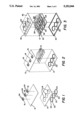
- FIGS. 1-3 are schematic illustrations of the construction of a disposable pump cassette in accordance with the invention.
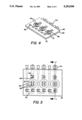
- FIG. 4 is a perspective view of the disposable pump cassette constructed in accordance with the invention.
- FIG. 5 is a plan view of the cassette of FIG. 4;
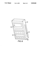
- FIG. 6 is a perspective view of an ambulatory pump instrument for use with the cassette of FIG. 1;
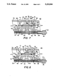
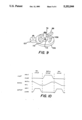
- FIG. 7 is a schematic cross-section, along line 7--7 of FIG. 5, illustrating the cooperation of the cassette with the drive means of the instrument, with the pump chamber shown in the full position, ready to pump;
- FIG. 8 is a view similar to FIG. 7, with the pump chamber emptying during a pumping stroke;
- FIG. 9 is a schematic illustration of the instrument drive means camming system for the pumping chamber and inlet valve
- FIG. 10 is a timing diagram illustrating a pump cycle
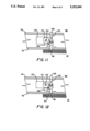
- FIG. 11 is a schematic cross-sectional view illustrating a fail-safe shut down valve on the instrument, with the valve closed;
- FIG. 12 is a view similar to FIG. 11, with the fail-safe valve open.
- FIGS. 1 through 3 The construction of a cassette 10 for an ambulatory parenteral pump providing pumping of three separate infusates is depicted in FIGS. 1 through 3.
- Three fluid paths in the cassette are provided between an upper flexible plastic sheet 12 and a lower flexible plastic sheet 14.
- Sheets 12 and 14 may be formed from any suitable flexible plastic material such as polyvinylchloride.
- Upper sheet 12 is provided with three spaced pump piston plates 16 on its upper surface.
- Lower flexible sheet 14 has three spaced die-cut apertures 18 in register with piston plates 16.
- Three rigid cup shaped members 20 are positioned beneath lower sheet 14 in surrounding relationship to apertures 18. Securement of rigid cups 20 underlying apertures 18 may be affected by radio frequency welding of cup surrounding flanges 22 to the underside of flexible sheet 14.
- piston plates 16 may be secured to the upper flexible sheet by radio frequency welding.
- Each piston plate 16 has integrally formed therewith a pair of opposed upstanding catch members 24 which protrude upwardly from piston plate 16 away from flexible sheet 12.
- Sheets 12 and 14 may be secured together in a single step by radio frequency welding.
- the sealing includes definition of an inlet fluid path 28 corresponding to each rigid cup shaped member 20 and an outlet fluid path 30 leading from each rigid cup shaped member 20.
- the inlet path 28 and outlet path 30 corresponding to each cup shaped member 20 are arranged so that they terminate at the same edge 32 of bonded sheets 12 and 14 in side-by-side relationship.
- Each inlet and outlet is provided with a Luer fitting 34 of conventional configuration for connection to upstream and downstream tubing connecting the cassette to, respectively, a fluid source and a patient.
- Sheets 12 and 14 are sealed about the periphery of aperture 18 so as to form a pumping chamber 36 with each cup shaped member 20.
- flexible sheets 12 and 14 define a series of three sealed independent flow paths, each extending from an inlet 28 with fitting 34, through a pump chamber 36, to an outlet 38 with fitting 34.
- upper rigid housing member 40 is provided with three apertures 44 each surrounding pump chamber 36 and permitting upstanding catch members 24 to extend upwardly through upper housing member 40.
- the surface of upper housing member 40 is also provided with nine living hinge members formed therein, and designated by the reference numeral 46.
- One of the living hinge members 46 overlies the inlet channel 28 of each fluid flow path.
- Two of the living hinge members 46 are provided at spaced locations along each outlet channel 30.
- the lower portion of each living hinge member 46 is provided with downwardly extending protrusion 48 which will act, upon application of force to its living hinge 46, to shut off the underlying flow channel formed between flexible sheets 12 and 14.
- Lower rigid housing member 42 is provided with an aperture 50 for receiving each of the rigid cup members 20 of flexible sheet 14.
- the assembled cassette as seen in FIGS. 4 and 5, thus provides fluid inlet and outlet connections for three isolated fluid paths, each of which extends through a pump chamber.
- the rigid housing provides access to catch means 24 for exercising the pump chamber.
- Living hinges 46 provide the capability of shutting off the inlet channel and the outlet channel, the latter at two spaced locations.
- the pump cassette provides, in one compact and inexpensive package, three essentially identical isolated fluid paths for controlling infusions of three infusates. Infusion may proceed, by the clinician's selection of downstream tubing configurations, into separate patient sites or into a single delivery cannula.
- FIG. 6 illustrates a compact ambulatory pump instrument 60 for receiving and exercising the pumping cassette 10.
- Instrument 60 has a case 62 with a cassette receiving slot 64 formed in its side.
- a conventional keyboard 66 is provided for inputting infusion instructions for each of the three independent fluid paths.
- a conventional display 68 is provided for displaying alpha/numeric information for setup instructions, input data and information concerning infusions in progress.
- Instrument 60 is powered conventionally using a battery. As conventional, the instrument may also be powered by AC connection as, for example, when the patient has retired to bed or other fixed location.
- the pumping and valving operations on each of the cassette fluid paths are provided in instrument 60 by three identical mechanisms, a single one of which is shown in operating position with cassette 10 in FIGS. 7 and 8.
- the mechanism includes inlet valve shaft 70, outlet valve shaft 72, and pumping shaft 74, each carried slidingly by apertures in front bezel 76 and spaced rear mounting plate 78.
- Cassette 10 is held firmly against front bezel 76 in operating position by a conventional holding mechanism (not shown). In this position, inlet valve shaft 70 directly confronts and engages the living hinge 46 overlying the inlet fluid channel 28 for one fluid.
- Shaft 70 is biased to the retracted or open position by spring 80 mounted about shaft 70 between front bezel 76 and shoulder 82 carried fixedly by shaft 70.
- a force receiving member 84 is mounted around shaft 70 so that it may float up and down with respect to the shaft on overriding spring 86.
- the lower end of spring 86 is mounted on shoulder 82.
- Shaft 70 may be extended toward cassette 10 to cause the living hinge projection 48 to close inlet channel 28 by application of force on member 84 through lever 88 pivoted at fulcrum 90, as shown in FIG. 8.
- Outlet valve shaft 72 is not operated directly by the instrument 60, but is biased to the closing position by spring 92 bearing on shoulder 94 to cause living hinge 46 overlying inlet channel 30 to close the channel. The valve is thus normally closed, but responsive to fluid pressure in the pump chamber 36 to open and permit flow outwardly along outlet channel 30 from pumping chamber 36.
- Outlet valve shaft 72 includes a magnetically permeable portion 96 for tracking the position of shaft 72. Hall effect sensor 98 is mounted to the front bezel 76 adjacent magnetic portion 96 to detect the position of the valve.
- Pumping shaft 74 includes a drive head 104 which is captured by the upstanding catch members 24 so that it is held tightly against piston plate 16. By this engagement, reciprocal movement of the drive shaft 74 will cause piston plate 16 to be moved toward and away from the cup shaped member 20 defining the pump chamber 36 in cassette 10. Actuation of inlet valve shaft 70 and pump drive shaft 74 is effected by unidirectional driving of camming gear 106 which rotates about shaft 74. The upper surface of gear 106 carries outer inlet valve camming surface 108 and inner pump camming surface 110. Gear 106 is driven by a drive gear 107 (FIG. 9) carried in instrument 60, which is rotated by an electric motor (not shown). Inlet valve camming surface 108 causes the lever 88 to advance and retract inlet valve shaft 70. Piston shaft 74 carries a camming pin 112 which is kept in contact with camming surface 110 by spring 114.
- FIG. 10 illustrates the cycle of movement of valve shaft 70 and pumping shaft 74 under the control, of camming gear 106.
- the lower curve in FIG. 10 illustrates the pressure response of the passive outlet valve of shaft 72.
- inlet shaft 70 is held in the closed position, occluding channel 28.
- Piston plate 16 is in the retracted or refill position, indicating a full load in pumping chamber 36.
- Pumping begins initially by causing the pumping shaft 74 to advance propelling the plate 16 toward pumping chamber 36. As pressure builds in pumping chamber 36, outlet valve shaft 72 opens to permit flow outwardly through outlet channel 30.
- FIGS. 11 and 12 there is depicted a fail-safe closure valve for operation on the most downstream living hinge 48 for each fluid path.
- a single motor operating through three cams, one for each of the three fluid paths, all fluid paths of the cassette may be placed in the no-flow condition in response to any selected alarm messages.
- a shutdown motor 120 drives three cams 122 mounted on gear shaft 124. The cams are operable between a first closed position depicted in FIG. 11 and a second open position depicted in FIG. 12. Through lever 126, each cam 122 operates to position fail-safe valve shaft 128, which is biased by spring 130 to the closed position depicted in FIG. 11.
Abstract
An ambulatory parenteral fluid infusion pump employs a disposable in-line cassette which provides three independent fluid paths between two flexible plastic sheets. The fluid path extends through a pump chamber having a piston plate secured to the flexible sheet at each pumping chamber. The sealed flexible sheets are housed in a rigid housing which provides an aperture through which a catch member formed on the piston plate extends, and having living hinges overlying the inlet and outlet paths for shutting off those paths. An outlet valve is normally closed, and operates in response to buildup of fluid pressure from advancement of the piston plate into the pump chamber to deliver fluid.
Description
This invention relates to parenteral infusion pumps, and more particularly to an ambulatory pump with disposable in-line cassette suitable for independently controlled infusion of three fluids.
The provision of instrumentation for the accurate infusion of intravenous fluids to patients has received substantial attention over the past two decades. Devices for providing controlled gravity flow, as well as flow induced by mechanical pressure, have been provided which consist of two major elements The first is an instrument which the clinician programs with desired flow parameters and which contains electromechanical elements for controlling and monitoring flow. Such instruments ordinarily cooperate with an intravenous tubing set having a sealed fluid path which does not come in contact with the instrument. Typically included in the tubing set is an in-line cassette or other flow element which is positioned in the instrument during use.
The present invention provides a compact pump instrument suitable for wearing by an ambulatory patient, operating with a disposable in-line cassette providing the necessary valving and pumping functions for the infusion of three different fluids along independent flow paths. A device constructed in accordance with the invention is relatively simple and inexpensive, and employs a valving system which is not dependent upon the accuracy of alignment of the disposable cassette in the pump instrument. Despite the compactness of the pump instrument and the small size and simplicity of the disposable cassette, the system constructed in accordance with this invention permits the clinician to input independent flow rates and other flow parameters for three distinct fluids which are pumped along isolated flow paths to the output of the system. The fluids may be pumped simultaneously or sequentially, and the fluid output may be conveyed separately to distinct patient infusion sites, or combined in a single patient line as desired.
The pumping instrument of the invention utilizes a single drive motor for each fluid independently operated to actuate all of the essential pumping and valving actions necessary for accurate volumetric infusion of that fluid. In addition, a single drive is provided to actuate fail-safe shut down valving means of all fluid paths through the system.
In accordance with the invention, there is provided a disposable pump chamber cassette including a flexible diaphragm defining a chamber having an inlet and an outlet. A piston plate is secured to the flexible diaphragm adjacent the pump chamber and includes a upstanding catch. The cassette cooperates with an instrument which receives the cassette and incorporates drive means engaging the piston plate catch and moving the piston plate back and forth to draw fluid into, and expel fluid from, the pump chamber. Inlet valve closure means are carried by the instrument for closing the inlet of the pump chamber at selected times. A pressure responsive normally-closing outlet valve means is carried by the instrument for closing the outlet of the pump chamber except when the chamber is driven to an elevated pressure by the drive means, during which time it automatically opens.
In the specific embodiment disclosed, the cassette includes an array of three sets of pump chambers, piston plates, valves, and inlets and outlets, and the instrument includes pumping and valve means to independently drive the three portions of the cassette for independent and isolated delivery of three fluids.
In a specific embodiment of the invention, the pressure responsive outlet valve is monitored by sensing means to determine the position of the outlet valve. In a further aspect of the invention, fail-safe shutoff means is provided for closing the outlet of all chambers of the cassette.
In a specific form of the invention, the cassette includes two flexible plastic sheets welded together to form three fluid paths, each extending from an inlet to an outlet extending through a pumping chamber positioned between the sheets. One wall of the pumping chamber may be formed by a rigid cup shaped member adhered to one of the flexible sheets at an aperture therein.
In a preferred embodiment of the invention, each fluid path extends from an inlet to an outlet provided side by side on the edge of the cassette so as to be accessible when the cassette is installed in the instrument.
For a more complete understanding of the present invention and for further advantages thereof, reference is now made to the following Description of the Preferred Embodiment taken in conjunction with the accompanying Drawings in which:
FIGS. 1-3 are schematic illustrations of the construction of a disposable pump cassette in accordance with the invention;
FIG. 4 is a perspective view of the disposable pump cassette constructed in accordance with the invention;
FIG. 5 is a plan view of the cassette of FIG. 4;
FIG. 6 is a perspective view of an ambulatory pump instrument for use with the cassette of FIG. 1;
FIG. 7 is a schematic cross-section, along line 7--7 of FIG. 5, illustrating the cooperation of the cassette with the drive means of the instrument, with the pump chamber shown in the full position, ready to pump;
FIG. 8 is a view similar to FIG. 7, with the pump chamber emptying during a pumping stroke;
FIG. 9 is a schematic illustration of the instrument drive means camming system for the pumping chamber and inlet valve;
FIG. 10 is a timing diagram illustrating a pump cycle;
FIG. 11 is a schematic cross-sectional view illustrating a fail-safe shut down valve on the instrument, with the valve closed; and
FIG. 12 is a view similar to FIG. 11, with the fail-safe valve open.
The construction of a cassette 10 for an ambulatory parenteral pump providing pumping of three separate infusates is depicted in FIGS. 1 through 3. Three fluid paths in the cassette are provided between an upper flexible plastic sheet 12 and a lower flexible plastic sheet 14. Sheets 12 and 14 may be formed from any suitable flexible plastic material such as polyvinylchloride. Upper sheet 12 is provided with three spaced pump piston plates 16 on its upper surface. Lower flexible sheet 14 has three spaced die-cut apertures 18 in register with piston plates 16. Three rigid cup shaped members 20 are positioned beneath lower sheet 14 in surrounding relationship to apertures 18. Securement of rigid cups 20 underlying apertures 18 may be affected by radio frequency welding of cup surrounding flanges 22 to the underside of flexible sheet 14. Likewise, piston plates 16 may be secured to the upper flexible sheet by radio frequency welding. Each piston plate 16 has integrally formed therewith a pair of opposed upstanding catch members 24 which protrude upwardly from piston plate 16 away from flexible sheet 12.
Sheets 12 and 14 may be secured together in a single step by radio frequency welding. The sealing includes definition of an inlet fluid path 28 corresponding to each rigid cup shaped member 20 and an outlet fluid path 30 leading from each rigid cup shaped member 20. The inlet path 28 and outlet path 30 corresponding to each cup shaped member 20 are arranged so that they terminate at the same edge 32 of bonded sheets 12 and 14 in side-by-side relationship. Each inlet and outlet is provided with a Luer fitting 34 of conventional configuration for connection to upstream and downstream tubing connecting the cassette to, respectively, a fluid source and a patient. Sheets 12 and 14 are sealed about the periphery of aperture 18 so as to form a pumping chamber 36 with each cup shaped member 20. Thus, flexible sheets 12 and 14 define a series of three sealed independent flow paths, each extending from an inlet 28 with fitting 34, through a pump chamber 36, to an outlet 38 with fitting 34.
The sealed flexible sheets 12 and 14 are then secured between upper rigid housing member 40 and lower rigid housing member 42 by means of sonic welding around the periphery of the cassette, capturing the flexible diaphragm sheets 12 and 14 and their sealed flow paths in fixed geometric relationship to the housing members 40 and 42. Upper rigid housing member 40 is provided with three apertures 44 each surrounding pump chamber 36 and permitting upstanding catch members 24 to extend upwardly through upper housing member 40. The surface of upper housing member 40 is also provided with nine living hinge members formed therein, and designated by the reference numeral 46. One of the living hinge members 46 overlies the inlet channel 28 of each fluid flow path. Two of the living hinge members 46 are provided at spaced locations along each outlet channel 30. As seen in FIG. 5, in phantom, the lower portion of each living hinge member 46 is provided with downwardly extending protrusion 48 which will act, upon application of force to its living hinge 46, to shut off the underlying flow channel formed between flexible sheets 12 and 14.
Lower rigid housing member 42 is provided with an aperture 50 for receiving each of the rigid cup members 20 of flexible sheet 14. The assembled cassette, as seen in FIGS. 4 and 5, thus provides fluid inlet and outlet connections for three isolated fluid paths, each of which extends through a pump chamber. The rigid housing provides access to catch means 24 for exercising the pump chamber. Living hinges 46 provide the capability of shutting off the inlet channel and the outlet channel, the latter at two spaced locations. The pump cassette provides, in one compact and inexpensive package, three essentially identical isolated fluid paths for controlling infusions of three infusates. Infusion may proceed, by the clinician's selection of downstream tubing configurations, into separate patient sites or into a single delivery cannula.
FIG. 6 illustrates a compact ambulatory pump instrument 60 for receiving and exercising the pumping cassette 10. Instrument 60 has a case 62 with a cassette receiving slot 64 formed in its side. A conventional keyboard 66 is provided for inputting infusion instructions for each of the three independent fluid paths. A conventional display 68 is provided for displaying alpha/numeric information for setup instructions, input data and information concerning infusions in progress. Instrument 60 is powered conventionally using a battery. As conventional, the instrument may also be powered by AC connection as, for example, when the patient has retired to bed or other fixed location.
The pumping and valving operations on each of the cassette fluid paths are provided in instrument 60 by three identical mechanisms, a single one of which is shown in operating position with cassette 10 in FIGS. 7 and 8. The mechanism includes inlet valve shaft 70, outlet valve shaft 72, and pumping shaft 74, each carried slidingly by apertures in front bezel 76 and spaced rear mounting plate 78. Cassette 10 is held firmly against front bezel 76 in operating position by a conventional holding mechanism (not shown). In this position, inlet valve shaft 70 directly confronts and engages the living hinge 46 overlying the inlet fluid channel 28 for one fluid. Shaft 70 is biased to the retracted or open position by spring 80 mounted about shaft 70 between front bezel 76 and shoulder 82 carried fixedly by shaft 70. A force receiving member 84 is mounted around shaft 70 so that it may float up and down with respect to the shaft on overriding spring 86. The lower end of spring 86 is mounted on shoulder 82. Shaft 70 may be extended toward cassette 10 to cause the living hinge projection 48 to close inlet channel 28 by application of force on member 84 through lever 88 pivoted at fulcrum 90, as shown in FIG. 8.
Outlet valve shaft 72 is not operated directly by the instrument 60, but is biased to the closing position by spring 92 bearing on shoulder 94 to cause living hinge 46 overlying inlet channel 30 to close the channel. The valve is thus normally closed, but responsive to fluid pressure in the pump chamber 36 to open and permit flow outwardly along outlet channel 30 from pumping chamber 36. Outlet valve shaft 72 includes a magnetically permeable portion 96 for tracking the position of shaft 72. Hall effect sensor 98 is mounted to the front bezel 76 adjacent magnetic portion 96 to detect the position of the valve.
Pumping shaft 74 includes a drive head 104 which is captured by the upstanding catch members 24 so that it is held tightly against piston plate 16. By this engagement, reciprocal movement of the drive shaft 74 will cause piston plate 16 to be moved toward and away from the cup shaped member 20 defining the pump chamber 36 in cassette 10. Actuation of inlet valve shaft 70 and pump drive shaft 74 is effected by unidirectional driving of camming gear 106 which rotates about shaft 74. The upper surface of gear 106 carries outer inlet valve camming surface 108 and inner pump camming surface 110. Gear 106 is driven by a drive gear 107 (FIG. 9) carried in instrument 60, which is rotated by an electric motor (not shown). Inlet valve camming surface 108 causes the lever 88 to advance and retract inlet valve shaft 70. Piston shaft 74 carries a camming pin 112 which is kept in contact with camming surface 110 by spring 114.
This camming action is schematically illustrated in FIG. 9. FIG. 10 illustrates the cycle of movement of valve shaft 70 and pumping shaft 74 under the control, of camming gear 106. The lower curve in FIG. 10 illustrates the pressure response of the passive outlet valve of shaft 72. At the start of the time period depicted in FIG. 10, inlet shaft 70 is held in the closed position, occluding channel 28. Piston plate 16 is in the retracted or refill position, indicating a full load in pumping chamber 36. Pumping begins initially by causing the pumping shaft 74 to advance propelling the plate 16 toward pumping chamber 36. As pressure builds in pumping chamber 36, outlet valve shaft 72 opens to permit flow outwardly through outlet channel 30. This condition is maintained until pumping shaft 74 completes its downward travel with the piston plate 16 ceasing to pressurize chamber 36. The opening and closing of outlet valve shaft 72 is sensed by sensor 98 so that the instrument has verification of the amount of movement of pumping shaft 74, and thus piston plate 16 during the time outlet channel 30 is open. After closing of the outlet channel 30, the inlet valve shaft 70 is moved to the open position, and the piston shaft 74 subsequently retracted, pulling fluid into chamber 36 through inlet 28 as piston plate 16 moves toward its initial retracted position. Then inlet valve shaft 70 is advanced to close channel 28, and the cycle begins again.
It will be appreciated that the foregoing arrangement has a number of advantages. The precise cycling of inlet valve and pump is controlled by a single camming gear 106 which is driven in a single direction. The fabrication of the cassette 10 aligns the living hinges 56 and inlet and outlet channels 28 and 30 so that accurate closure capability is established in the fabrication process for cassette 10, and not through the alignment of individual disposable cassettes 10 in the instrument 60.
In FIGS. 11 and 12, there is depicted a fail-safe closure valve for operation on the most downstream living hinge 48 for each fluid path. By a single motor operating through three cams, one for each of the three fluid paths, all fluid paths of the cassette may be placed in the no-flow condition in response to any selected alarm messages. For example, if the outlet valve sensor 98 fails to detect proper movement of outlet valve shaft 72 in response to the pumping cycle, a message can be sent to the system for shutdown of all three fluid paths. A shutdown motor 120 drives three cams 122 mounted on gear shaft 124. The cams are operable between a first closed position depicted in FIG. 11 and a second open position depicted in FIG. 12. Through lever 126, each cam 122 operates to position fail-safe valve shaft 128, which is biased by spring 130 to the closed position depicted in FIG. 11.
Whereas the present invention has been described with respect to a specific embodiment thereof, it will be understood that various changes and modifications will be suggested to one skilled in the art and it is intended to encompass such changes and modifications as fall within the scope of the appended claims.
Claims (23)
1. A parenteral fluid pump comprising:
(a) a disposable pump chamber cassette including a flexible diaphragm defining a chamber having an inlet and an outlet;
(b) a piston plate welded to the flexible diaphragm of the pump chamber, including an upstanding catch;
(c) an instrument for receiving the disposable cassette in an operating position;
(d) drive means carried by the instrument including means for engaging the piston plate catch and moving the piston plate back and forth to draw fluid into, and expel fluid from the pump chamber;
(e) inlet valve closure means carried by the instrument for closing the inlet of the pump chamber at selected times;
(f) pressure responsive normally-closing outlet valve means carried by the instrument for closing the outlet of the pump chamber except when the chamber is driven to an elevated pressure by the drive means.
2. The pump of claim 1, wherein the cassette includes two additional sets of pump chambers, piston plates, inlet and outlets, and the instrument includes two additional sets of drive and valve means for independent and isolated delivery of two additional infusates.
3. The pump of claim 1, further comprising sensing means for sensing the position of the outlet valve means.
4. The pump of claim 1, further comprising fail-safe shut-off means for closing the outlet of the chamber.
5. The pump of claim 4, wherein the shut-off means responds at least to the sensing means.
6. The pump of claim 1, wherein the cassette includes a rigid housing encompassing the pump chamber having an aperture through which the piston plate catch extends, and a living hinge overlying the pump chamber inlet for engagement by the inlet valve closure means, and a living hinge overlying the pump chamber outlet for engagement by the outlet valve means.
7. A disposable cassette for an intravenous pump comprising:
a. a first flexible plastic sheet;
b. a second flexible plastic sheet having an aperture formed therein and having a rigid cup-shaped member adhered thereto about the aperture to form a pumping chamber wall; said second flexible sheet being selectively welded to the first flexible sheet to form an inlet channel leading from an edge of the cassette to the cup-shaped member, an outlet channel leading from the cup-shaped member to an edge of the cassette, and a generally circular seal around the cup-shaped member to form the pumping chamber;
c. a flat pumping plate secured to the first flexible sheet opposite the cup-shaped member, and having an upstanding catch;
d. a rigid housing enclosing the first and second flexible plastic sheets and having an aperture through, which the catch extends, and having a first living hinge formed on its surface overlying the inlet channel, and a second living hinge formed on its surface overlying the outlet channel; and
e. fittings secured at the edge of the rigid housing communicating with the inlet and outlet channels, so that a fluid circuit is formed extending between said fittings through a pump chamber formed by the cup-shaped member and the first flexible sheet, whereby the pump chamber may be activated by mechanical interface with the catch, and the inlet and outlet channels may be closed at selected times by external pressure on the living hinges of the rigid housing.
8. The cassette of claim 7, wherein the pumping plate is circular, and the catch comprises a pair of spaced arms upstanding from the plate with confronting detent shoulders formed on the arms.
9. The cassette of claim 7, wherein the cup-shaped member includes a surrounding flange which is seamed to the second flexible sheet.
10. A disposable cassette for an intravenous pump comprising:
a. a first flexible plastic sheet;
b. a second flexible plastic sheet having three spaced apertures formed therein and having three rigid cup-shaped members adhered thereto about the apertures, each forming a wall of a pumping chamber; said second flexible sheet being selectively welded to the first flexible sheet to form an inlet channel leading from an edge of the cassette to each cup-shaped member, an outlet channel leading from each cup-shaped member to an edge of the cassette, and a generally circular seal around each cup-shaped member to form said pumping chamber;
c. a rigid catch secured to the first flexible sheet opposite each cup-shaped member;
d. a rigid housing enclosing the first and second flexible plastic sheets and having an aperture through which each catch extends, and having a first living hinge formed on its surface overlying each inlet channel, and a second living hinge formed on its surface overlying each outlet channel; and
e. fittings secured at the edge of the rigid housing communicating with the inlet and outlet channels so that three isolated and independent fluid circuits are formed, each extending between a pair of fittings through a pumping chamber formed by one of said cup shaped members and the first flexible sheet, whereby each pumping chamber may be activated independently by mechanical interface with its catch, and each inlet and outlet channel may be closed at selected times by external pressure on the living hinges of the rigid housing.
11. The cassette of claim 10, wherein the catch comprises a pair of upstanding spaced arms with confronting detent shoulders formed on the arms.
12. The cassette of claim 10, wherein the cup-shaped member includes a surrounding flange which is secured to the second flexible sheet.
13. A disposable cassette for an intravenous pump comprising:
a. a first flexible plastic sheet;
b. a second flexible plastic sheet selectively welded to the first flexible sheet to form a pumping chamber, an inlet channel leading from an edge of the cassette to the pumping chamber and an outlet channel leading from the pumping chamber to an edge of the cassette;
c. a flat pumping plate secured to the first flexible sheet adjacent the pumping chamber;
d. an upstanding catch formed on the pumping plate opposite the first flexible sheet; and
e. fittings secured at an edge of the cassette communicating with the inlet and outlet channels so that a fluid circuit is formed extending between said fittings through the pumping chamber.
14. The cassette of claim 13, wherein the catch comprises a pair of spaced arms formed with opposed detent shoulders.
15. A disposable cassette for an intravenous pump comprising:
a. a first flexible plastic sheet;
b. a second flexible plastic sheet having an aperture former therein and having a rigid cup-shaped member adhered about the aperture to form a pumping chamber, said second flexible sheet being selectively welded to the first flexible sheet to form an inlet channel leading from an edge of the cassette to the cup-shaped member, an outlet channel leading from the cup-shaped member to an edge of the cassette, and a circular seal around the cup-shaped member to form the pumping chamber;
c. a flat pumping plate, secured to the first flexible sheet opposite the cup-shaped member;
d. a catch formed on the plate opposite the first flexible sheet; and
e. fittings secured at an edge of the cassette communicating with the inlet and outlet channels so that a fluid circuit is formed extending between said fittings through a pumping chamber formed in the cassette between the cup-shaped member and the first flexible sheet.
16. The cassette of claim 15, wherein the cup-shaped member includes a surrounding flange which is bonded to the second flexible sheet.
17. A disposable cassette for an intravenous pump comprising:
a. a first flexible plastic sheet;
b. a second flexible plastic sheet having an aperture formed therein and having a rigid cup-shaped member adhered thereto to form a wall of a pumping chamber; said second flexible sheet being selectively welded to the first flexible sheet to form an inlet channel leading from an edge of the cassette to each cup-shaped member, an outlet channel leading from each cup-shaped member to an edge of the cassette, and a circular seal around each cup-shaped member to form a pumping chamber;
c. a rigid catch secured to the first flexible sheet opposite each cup-shaped member; and
d. a rigid housing enclosing the first and second flexible plastic sheets and having an aperture through which the rigid catch extends.
18. The cassette of claim 17, wherein the catch comprises a pair of upstanding spaced arms with confronting detent shoulders formed on the arms.
19. The cassette of claim 17, wherein the cup-shaped member includes a surrounding flange which is secured to the second flexible sheet.
20. A disposable cassette for an intravenous pump comprising a pair of flexible plastic sheets selectively welded together to form:
a. a first pumping chamber;
b. a first inlet channel leading from an edge of the cassette to the first pumping chamber having a first inlet valve site;
c. a first outlet channel leading from the first pumping chamber to an edge of the cassette having a first outlet valve site;
d. a second pumping chamber;
e. a second inlet channel leading from an edge of the cassette to the second pumping chamber having a second inlet valve site;
f. a second outlet channel leading from the second pumping chamber to an edge of the cassette having a second outlet valve site;
g. a third pumping chamber;
h. a third inlet channel leading from an edge of the cassette to the third pumping chamber having a third inlet valve site; and
i. a third outlet channel leading from the third pumping chamber to an edge of the cassette having a third outlet valve site, whereby three fluids may be pumped through the cassette along three isolated and independent paths.
21. The cassette of claim 20, further comprising a rigid housing enclosing the flexible sheets.
22. The cassette of claim 21, further comprising living hinges formed on one surface of the rigid housing, one overlying each valve site.
23. A disposable cassette for an intravenous pump comprising:
a. a first flexible plastic sheet;
b. a second flexible plastic sheet selectively welded to the first flexible sheet to form a pumping chamber, an inlet channel leading from an edge of the cassette to the pumping chamber, an outlet channel leading from the pumping chamber to an edge of the cassette; a seal around the cup-shaped member to form said pumping chamber;
c. a catch secured to the first flexible sheet opposite the cup-shaped member; and
d. a rigid housing enclosing the first and second flexible plastic sheets and having an aperture through which the catch extends, and having a first living hinge formed on its surface overlying the inlet channel, and a second living hinge formed on its surface overlying the outlet channel.
Priority Applications (1)
| Application Number | Priority Date | Filing Date | Title |
|---|---|---|---|
| US07/963,636 US5252044A (en) | 1992-10-20 | 1992-10-20 | Parenteral fluid pump with disposable cassette |
Applications Claiming Priority (1)
| Application Number | Priority Date | Filing Date | Title |
|---|---|---|---|
| US07/963,636 US5252044A (en) | 1992-10-20 | 1992-10-20 | Parenteral fluid pump with disposable cassette |
Publications (1)
| Publication Number | Publication Date |
|---|---|
| US5252044A true US5252044A (en) | 1993-10-12 |
Family
ID=25507499
Family Applications (1)
| Application Number | Title | Priority Date | Filing Date |
|---|---|---|---|
| US07/963,636 Expired - Fee Related US5252044A (en) | 1992-10-20 | 1992-10-20 | Parenteral fluid pump with disposable cassette |
Country Status (1)
| Country | Link |
|---|---|
| US (1) | US5252044A (en) |
Cited By (69)
| Publication number | Priority date | Publication date | Assignee | Title |
|---|---|---|---|---|
| US5405252A (en) * | 1993-01-06 | 1995-04-11 | Nikkanen; Erik | Metering pump |
| US5460490A (en) * | 1994-05-19 | 1995-10-24 | Linvatec Corporation | Multi-purpose irrigation/aspiration pump system |
| US5482446A (en) * | 1994-03-09 | 1996-01-09 | Baxter International Inc. | Ambulatory infusion pump |
| US5593290A (en) * | 1994-12-22 | 1997-01-14 | Eastman Kodak Company | Micro dispensing positive displacement pump |
| US5658133A (en) * | 1994-03-09 | 1997-08-19 | Baxter International Inc. | Pump chamber back pressure dissipation apparatus and method |
| US5989423A (en) * | 1993-03-03 | 1999-11-23 | Deka Products Limited Partnership | Disposable cassette, delivery set and system for peritoneal dialysis |
| GB2338755A (en) * | 1996-04-10 | 1999-12-29 | Baxter Int | Infusion pump having a sealing fluid barrier |
| US6189736B1 (en) | 1997-01-17 | 2001-02-20 | Niagara Pump Corporation | Condiment dispensing apparatus |
| US6216573B1 (en) | 1995-06-07 | 2001-04-17 | Hydrocision, Inc. | Fluid jet cutting system |
| WO2002013970A2 (en) * | 2000-08-11 | 2002-02-21 | Lifescan, Inc. | Gimbaled bladder actuator for use with test strips |
| EP1235613A2 (en) * | 1997-02-14 | 2002-09-04 | NxStage Medical, Inc. | Fluid processing systems and methods using extracorporeal fluid flow panels oriented within a cartridge |
| US20030220605A1 (en) * | 2002-05-24 | 2003-11-27 | Bowman Joseph H. | Disposable medical fluid unit having rigid frame |
| US20030217957A1 (en) * | 2002-05-24 | 2003-11-27 | Bowman Joseph H. | Heat seal interface for a disposable medical fluid unit |
| US20030220608A1 (en) * | 2002-05-24 | 2003-11-27 | Bruce Huitt | Method and apparatus for controlling medical fluid pressure |
| US6764761B2 (en) | 2002-05-24 | 2004-07-20 | Baxter International Inc. | Membrane material for automated dialysis system |
| US6857366B1 (en) | 1999-11-02 | 2005-02-22 | Erik Nikkanen | Printing press ink transfer mechanism and employment of same |
| US6923792B2 (en) | 2001-08-08 | 2005-08-02 | Hydrocision, Inc. | Medical device with high pressure quick disconnect handpiece |
| US20060004303A1 (en) * | 2004-06-30 | 2006-01-05 | Weidenhaupt Klaus P | Fluid handling devices |
| US20080058712A1 (en) * | 2006-08-31 | 2008-03-06 | Plahey Kulwinder S | Peritoneal dialysis machine with dual voltage heater circuit and method of operation |
| US20080118378A1 (en) * | 2006-11-16 | 2008-05-22 | Vitality Food Service Inc. | Metering pump for dispensing liquid |
| US20090149743A1 (en) * | 2005-11-21 | 2009-06-11 | Acist Medical Systems, Inc. | Medical Fluid Injection System |
| US7717685B2 (en) | 2001-04-27 | 2010-05-18 | Hydrocision, Inc. | High pressure pumping cartridges for medical and surgical pumping and infusion applications |
| US7731689B2 (en) | 2007-02-15 | 2010-06-08 | Baxter International Inc. | Dialysis system having inductive heating |
| US7744554B2 (en) | 2002-12-31 | 2010-06-29 | Baxter International Inc. | Cassette alignment and integrity testing for dialysis systems |
| US7789849B2 (en) | 2002-05-24 | 2010-09-07 | Baxter International Inc. | Automated dialysis pumping system using stepper motor |
| US20110004143A1 (en) * | 2009-07-01 | 2011-01-06 | Michael James Beiriger | Drug Delivery Devices And Related Systems And Methods |
| US20110015610A1 (en) * | 2009-07-15 | 2011-01-20 | Fresenius Medical Care Holdings, Inc. | Medical fluid cassettes and related systems and methods |
| US7935074B2 (en) | 2005-02-28 | 2011-05-03 | Fresenius Medical Care Holdings, Inc. | Cassette system for peritoneal dialysis machine |
| US7998115B2 (en) | 2007-02-15 | 2011-08-16 | Baxter International Inc. | Dialysis system having optical flowrate detection |
| WO2011138244A1 (en) * | 2010-05-03 | 2011-11-10 | Wmf Württembergische Metallwarenfabrik Ag | Fluid pump |
| US8070709B2 (en) | 2003-10-28 | 2011-12-06 | Baxter International Inc. | Peritoneal dialysis machine |
| US8142653B2 (en) | 2002-06-04 | 2012-03-27 | Fresenius Medical Care Deutschland Gmbh | Medical fluid cassettes and related systems |
| US8172789B2 (en) | 2000-02-10 | 2012-05-08 | Baxter International Inc. | Peritoneal dialysis system having cassette-based-pressure-controlled pumping |
| US8192401B2 (en) | 2009-03-20 | 2012-06-05 | Fresenius Medical Care Holdings, Inc. | Medical fluid pump systems and related components and methods |
| US8323492B2 (en) | 2007-10-24 | 2012-12-04 | Baxter International Inc. | Hemodialysis system having clamping mechanism for peristaltic pumping |
| US8361023B2 (en) | 2007-02-15 | 2013-01-29 | Baxter International Inc. | Dialysis system with efficient battery back-up |
| US8545435B2 (en) | 2002-01-03 | 2013-10-01 | Baxter International, Inc. | Method and apparatus for providing medical treatment therapy based on calculated demand |
| US8558964B2 (en) | 2007-02-15 | 2013-10-15 | Baxter International Inc. | Dialysis system having display with electromagnetic compliance (“EMC”) seal |
| US8596997B2 (en) | 2009-05-08 | 2013-12-03 | Xavitech Ab | Membrane pump with magnetic coupling between an actuating means and the membrane |
| US8692167B2 (en) | 2010-12-09 | 2014-04-08 | Fresenius Medical Care Deutschland Gmbh | Medical device heaters and methods |
| US8720913B2 (en) | 2009-08-11 | 2014-05-13 | Fresenius Medical Care Holdings, Inc. | Portable peritoneal dialysis carts and related systems |
| US8870812B2 (en) | 2007-02-15 | 2014-10-28 | Baxter International Inc. | Dialysis system having video display with ambient light adjustment |
| US8932032B2 (en) | 2005-07-13 | 2015-01-13 | Fresenius Medical Care Holdings, Inc. | Diaphragm pump and pumping systems |
| US8992462B2 (en) | 2002-07-19 | 2015-03-31 | Baxter International Inc. | Systems and methods for performing peritoneal dialysis |
| US9011114B2 (en) | 2011-03-09 | 2015-04-21 | Fresenius Medical Care Holdings, Inc. | Medical fluid delivery sets and related systems and methods |
| US9144646B2 (en) | 2012-04-25 | 2015-09-29 | Fresenius Medical Care Holdings, Inc. | Vial spiking devices and related assemblies and methods |
| US9180240B2 (en) | 2011-04-21 | 2015-11-10 | Fresenius Medical Care Holdings, Inc. | Medical fluid pumping systems and related devices and methods |
| JP2015532871A (en) * | 2012-10-29 | 2015-11-16 | デバイオテック・ソシエテ・アノニム | Extracorporeal blood treatment device |
| US9186449B2 (en) | 2011-11-01 | 2015-11-17 | Fresenius Medical Care Holdings, Inc. | Dialysis machine support assemblies and related systems and methods |
| US20160051740A1 (en) * | 2014-08-21 | 2016-02-25 | Fenwal, Inc. | Magnet-Based Systems And Methods For Transferring Fluid |
| US9500188B2 (en) | 2012-06-11 | 2016-11-22 | Fresenius Medical Care Holdings, Inc. | Medical fluid cassettes and related systems and methods |
| US9514283B2 (en) | 2008-07-09 | 2016-12-06 | Baxter International Inc. | Dialysis system having inventory management including online dextrose mixing |
| US9561323B2 (en) | 2013-03-14 | 2017-02-07 | Fresenius Medical Care Holdings, Inc. | Medical fluid cassette leak detection methods and devices |
| US9582645B2 (en) | 2008-07-09 | 2017-02-28 | Baxter International Inc. | Networked dialysis system |
| US9610392B2 (en) | 2012-06-08 | 2017-04-04 | Fresenius Medical Care Holdings, Inc. | Medical fluid cassettes and related systems and methods |
| US9675745B2 (en) | 2003-11-05 | 2017-06-13 | Baxter International Inc. | Dialysis systems including therapy prescription entries |
| US9694125B2 (en) | 2010-12-20 | 2017-07-04 | Fresenius Medical Care Holdings, Inc. | Medical fluid cassettes and related systems and methods |
| US9987406B2 (en) | 2011-02-08 | 2018-06-05 | Fresenius Medical Care Holdings, Inc. | Magnetic sensors and related systems and methods |
| CN108261580A (en) * | 2011-08-02 | 2018-07-10 | 巴克斯特医疗保健股份有限公司 | Infusion pump and the method using infusion pump infusion fluid |
| CN108348679A (en) * | 2015-11-20 | 2018-07-31 | 先进微流控技术股份公司 | Micropump |
| US10064987B2 (en) | 2011-01-31 | 2018-09-04 | Fresenius Medical Care Holdings, Inc. | Preventing over-delivery of drug |
| CN108498900A (en) * | 2018-04-26 | 2018-09-07 | 上海富吉医疗器械有限公司 | The accurate device and its intravenous delivery system for adjusting flow velocity |
| US10117985B2 (en) | 2013-08-21 | 2018-11-06 | Fresenius Medical Care Holdings, Inc. | Determining a volume of medical fluid pumped into or out of a medical fluid cassette |
| US11179516B2 (en) | 2017-06-22 | 2021-11-23 | Baxter International Inc. | Systems and methods for incorporating patient pressure into medical fluid delivery |
| US11241530B1 (en) | 2020-11-23 | 2022-02-08 | Amf Medical Sa | Insulin patch pump having photoplethysmography module |
| US11529464B1 (en) | 2021-06-01 | 2022-12-20 | Amf Medical Sa | Systems and methods for monitoring delivery of microdoses of medication |
| US11529458B2 (en) | 2017-12-08 | 2022-12-20 | Amf Medical Sa | Drug delivery device |
| US11679199B2 (en) | 2021-06-01 | 2023-06-20 | Amf Medical Sa | Systems and methods for delivering microdoses of medication |
| US11857757B2 (en) | 2021-06-01 | 2024-01-02 | Tandem Diabetes Care Switzerland Sàrl | Systems and methods for delivering microdoses of medication |
Citations (23)
| Publication number | Priority date | Publication date | Assignee | Title |
|---|---|---|---|---|
| US3982534A (en) * | 1975-01-10 | 1976-09-28 | Buckman Thomas P | Intravenous administration system |
| US4094318A (en) * | 1976-07-09 | 1978-06-13 | Burron Medical Products, Inc. | Electronic control means for a plurality of intravenous infusion sets |
| US4155362A (en) * | 1976-01-26 | 1979-05-22 | Baxter Travenol Laboratories, Inc. | Method and apparatus for metered infusion of fluids |
| US4168288A (en) * | 1978-06-29 | 1979-09-18 | Briggs & Stratton Corporation | Combined carburetor and impulse fuel pump |
| US4191183A (en) * | 1977-10-31 | 1980-03-04 | Barry Mendelson | Mixing chamber for use in plural medical liquid intravenous administration set |
| US4199307A (en) * | 1977-07-05 | 1980-04-22 | Andros Incorporated | Medical infusion system |
| US4236880A (en) * | 1979-03-09 | 1980-12-02 | Archibald Development Labs, Inc. | Nonpulsating IV pump and disposable pump chamber |
| US4265240A (en) * | 1979-04-16 | 1981-05-05 | Imed Corporation | Apparatus for providing a controlled introduction of intravenous fluid to a patient |
| US4276004A (en) * | 1978-06-14 | 1981-06-30 | Messerschmitt-Boelkow-Biochm Gesellschaft Mit Beschrankter Haftung | Infusion pump |
| US4322201A (en) * | 1979-03-09 | 1982-03-30 | Avi, Inc. | IV Pump with back pressure control |
| US4382753A (en) * | 1979-03-09 | 1983-05-10 | Avi, Inc. | Nonpulsating IV pump and disposable pump chamber |
| US4391598A (en) * | 1981-04-28 | 1983-07-05 | Quest Medical, Inc. | Intravenous drug additive delivery system with electronic control |
| US4464172A (en) * | 1979-04-30 | 1984-08-07 | Lichtenstein Eric Stefan | Computer-control medical care system |
| US4468222A (en) * | 1976-05-24 | 1984-08-28 | Valleylab | Intravenous liquid pumping system and method |
| US4553958A (en) * | 1983-02-04 | 1985-11-19 | Quest Medical, Inc. | IV Delivery controller |
| US4657490A (en) * | 1985-03-27 | 1987-04-14 | Quest Medical, Inc. | Infusion pump with disposable cassette |
| US4696671A (en) * | 1984-02-08 | 1987-09-29 | Omni-Flow, Inc. | Infusion system having plural fluid input ports and at least one patient output port |
| US4705506A (en) * | 1984-11-29 | 1987-11-10 | Minnesota Mining And Manufacturing Company | Multiple solution IV system with setup error protection |
| US4753270A (en) * | 1985-10-01 | 1988-06-28 | Omni-Flow, Inc. | Cam actuator assembly for a programmable infusion system |
| US4828545A (en) * | 1984-02-08 | 1989-05-09 | Omni-Flow, Inc. | Pressure responsive multiple input infusion system |
| WO1991019098A1 (en) * | 1990-06-07 | 1991-12-12 | Humanteknik Ab | A valve arrangement and positive-displacement pump |
| US5100380A (en) * | 1984-02-08 | 1992-03-31 | Abbott Laboratories | Remotely programmable infusion system |
| US5108367A (en) * | 1984-02-08 | 1992-04-28 | Abbott Laboratories | Pressure responsive multiple input infusion system |
-
1992
- 1992-10-20 US US07/963,636 patent/US5252044A/en not_active Expired - Fee Related
Patent Citations (24)
| Publication number | Priority date | Publication date | Assignee | Title |
|---|---|---|---|---|
| US3982534A (en) * | 1975-01-10 | 1976-09-28 | Buckman Thomas P | Intravenous administration system |
| US4155362A (en) * | 1976-01-26 | 1979-05-22 | Baxter Travenol Laboratories, Inc. | Method and apparatus for metered infusion of fluids |
| US4468222A (en) * | 1976-05-24 | 1984-08-28 | Valleylab | Intravenous liquid pumping system and method |
| US4094318A (en) * | 1976-07-09 | 1978-06-13 | Burron Medical Products, Inc. | Electronic control means for a plurality of intravenous infusion sets |
| US4199307A (en) * | 1977-07-05 | 1980-04-22 | Andros Incorporated | Medical infusion system |
| US4191183A (en) * | 1977-10-31 | 1980-03-04 | Barry Mendelson | Mixing chamber for use in plural medical liquid intravenous administration set |
| US4276004A (en) * | 1978-06-14 | 1981-06-30 | Messerschmitt-Boelkow-Biochm Gesellschaft Mit Beschrankter Haftung | Infusion pump |
| US4168288A (en) * | 1978-06-29 | 1979-09-18 | Briggs & Stratton Corporation | Combined carburetor and impulse fuel pump |
| US4236880A (en) * | 1979-03-09 | 1980-12-02 | Archibald Development Labs, Inc. | Nonpulsating IV pump and disposable pump chamber |
| US4322201A (en) * | 1979-03-09 | 1982-03-30 | Avi, Inc. | IV Pump with back pressure control |
| US4382753A (en) * | 1979-03-09 | 1983-05-10 | Avi, Inc. | Nonpulsating IV pump and disposable pump chamber |
| US4265240A (en) * | 1979-04-16 | 1981-05-05 | Imed Corporation | Apparatus for providing a controlled introduction of intravenous fluid to a patient |
| US4464172A (en) * | 1979-04-30 | 1984-08-07 | Lichtenstein Eric Stefan | Computer-control medical care system |
| US4391598A (en) * | 1981-04-28 | 1983-07-05 | Quest Medical, Inc. | Intravenous drug additive delivery system with electronic control |
| US4553958A (en) * | 1983-02-04 | 1985-11-19 | Quest Medical, Inc. | IV Delivery controller |
| US4696671A (en) * | 1984-02-08 | 1987-09-29 | Omni-Flow, Inc. | Infusion system having plural fluid input ports and at least one patient output port |
| US4828545A (en) * | 1984-02-08 | 1989-05-09 | Omni-Flow, Inc. | Pressure responsive multiple input infusion system |
| US4865584A (en) * | 1984-02-08 | 1989-09-12 | Omni-Flow, Inc. | Cassette for programable multiple input infusion system |
| US5100380A (en) * | 1984-02-08 | 1992-03-31 | Abbott Laboratories | Remotely programmable infusion system |
| US5108367A (en) * | 1984-02-08 | 1992-04-28 | Abbott Laboratories | Pressure responsive multiple input infusion system |
| US4705506A (en) * | 1984-11-29 | 1987-11-10 | Minnesota Mining And Manufacturing Company | Multiple solution IV system with setup error protection |
| US4657490A (en) * | 1985-03-27 | 1987-04-14 | Quest Medical, Inc. | Infusion pump with disposable cassette |
| US4753270A (en) * | 1985-10-01 | 1988-06-28 | Omni-Flow, Inc. | Cam actuator assembly for a programmable infusion system |
| WO1991019098A1 (en) * | 1990-06-07 | 1991-12-12 | Humanteknik Ab | A valve arrangement and positive-displacement pump |
Cited By (174)
| Publication number | Priority date | Publication date | Assignee | Title |
|---|---|---|---|---|
| US5405252A (en) * | 1993-01-06 | 1995-04-11 | Nikkanen; Erik | Metering pump |
| US5989423A (en) * | 1993-03-03 | 1999-11-23 | Deka Products Limited Partnership | Disposable cassette, delivery set and system for peritoneal dialysis |
| US5482446A (en) * | 1994-03-09 | 1996-01-09 | Baxter International Inc. | Ambulatory infusion pump |
| US5658133A (en) * | 1994-03-09 | 1997-08-19 | Baxter International Inc. | Pump chamber back pressure dissipation apparatus and method |
| US5460490A (en) * | 1994-05-19 | 1995-10-24 | Linvatec Corporation | Multi-purpose irrigation/aspiration pump system |
| US5593290A (en) * | 1994-12-22 | 1997-01-14 | Eastman Kodak Company | Micro dispensing positive displacement pump |
| US6216573B1 (en) | 1995-06-07 | 2001-04-17 | Hydrocision, Inc. | Fluid jet cutting system |
| GB2338755A (en) * | 1996-04-10 | 1999-12-29 | Baxter Int | Infusion pump having a sealing fluid barrier |
| GB2338755B (en) * | 1996-04-10 | 2000-06-14 | Baxter Int | Volumetric infusion pump |
| US6189736B1 (en) | 1997-01-17 | 2001-02-20 | Niagara Pump Corporation | Condiment dispensing apparatus |
| US6213739B1 (en) | 1997-01-17 | 2001-04-10 | Niagara Pump Corporation | Linear peristaltic pump |
| EP1235613A4 (en) * | 1997-02-14 | 2009-08-12 | Nxstage Medical Inc | Fluid processing systems and methods using extracorporeal fluid flow panels oriented within a cartridge |
| EP1235613A2 (en) * | 1997-02-14 | 2002-09-04 | NxStage Medical, Inc. | Fluid processing systems and methods using extracorporeal fluid flow panels oriented within a cartridge |
| US6857366B1 (en) | 1999-11-02 | 2005-02-22 | Erik Nikkanen | Printing press ink transfer mechanism and employment of same |
| US8172789B2 (en) | 2000-02-10 | 2012-05-08 | Baxter International Inc. | Peritoneal dialysis system having cassette-based-pressure-controlled pumping |
| US8323231B2 (en) | 2000-02-10 | 2012-12-04 | Baxter International, Inc. | Method and apparatus for monitoring and controlling peritoneal dialysis therapy |
| US10322224B2 (en) | 2000-02-10 | 2019-06-18 | Baxter International Inc. | Apparatus and method for monitoring and controlling a peritoneal dialysis therapy |
| US8206339B2 (en) | 2000-02-10 | 2012-06-26 | Baxter International Inc. | System for monitoring and controlling peritoneal dialysis |
| US9474842B2 (en) | 2000-02-10 | 2016-10-25 | Baxter International Inc. | Method and apparatus for monitoring and controlling peritoneal dialysis therapy |
| US6866822B1 (en) | 2000-08-11 | 2005-03-15 | Lifescan, Inc. | Gimbaled bladder actuator for use with test strips |
| AU2001282985B2 (en) * | 2000-08-11 | 2005-06-09 | Lifescan, Inc. | Gimbaled bladder actuator for use with test strips |
| WO2002013970A3 (en) * | 2000-08-11 | 2002-07-04 | Lifescan Inc | Gimbaled bladder actuator for use with test strips |
| WO2002013970A2 (en) * | 2000-08-11 | 2002-02-21 | Lifescan, Inc. | Gimbaled bladder actuator for use with test strips |
| US7717685B2 (en) | 2001-04-27 | 2010-05-18 | Hydrocision, Inc. | High pressure pumping cartridges for medical and surgical pumping and infusion applications |
| US7951107B2 (en) | 2001-08-08 | 2011-05-31 | Hydrocision, Inc. | Medical device with high pressure quick disconnect handpiece |
| US6923792B2 (en) | 2001-08-08 | 2005-08-02 | Hydrocision, Inc. | Medical device with high pressure quick disconnect handpiece |
| US8545435B2 (en) | 2002-01-03 | 2013-10-01 | Baxter International, Inc. | Method and apparatus for providing medical treatment therapy based on calculated demand |
| US20040010223A1 (en) * | 2002-05-24 | 2004-01-15 | Don Busby | Fail safe system for operating medical fluid valves |
| US8684971B2 (en) | 2002-05-24 | 2014-04-01 | Baxter International Inc. | Automated dialysis system using piston and negative pressure |
| US7175606B2 (en) | 2002-05-24 | 2007-02-13 | Baxter International Inc. | Disposable medical fluid unit having rigid frame |
| US9675744B2 (en) | 2002-05-24 | 2017-06-13 | Baxter International Inc. | Method of operating a disposable pumping unit |
| US8403880B2 (en) | 2002-05-24 | 2013-03-26 | Baxter International Inc. | Peritoneal dialysis machine with variable voltage input control scheme |
| US7500962B2 (en) | 2002-05-24 | 2009-03-10 | Baxter International Inc. | Medical fluid machine with air purging pump |
| US9744283B2 (en) | 2002-05-24 | 2017-08-29 | Baxter International Inc. | Automated dialysis system using piston and negative pressure |
| US9504778B2 (en) | 2002-05-24 | 2016-11-29 | Baxter International Inc. | Dialysis machine with electrical insulation for variable voltage input |
| US6953323B2 (en) | 2002-05-24 | 2005-10-11 | Baxter International Inc. | Medical fluid pump |
| US9775939B2 (en) | 2002-05-24 | 2017-10-03 | Baxter International Inc. | Peritoneal dialysis systems and methods having graphical user interface |
| US8376999B2 (en) | 2002-05-24 | 2013-02-19 | Baxter International Inc. | Automated dialysis system including touch screen controlled mechanically and pneumatically actuated pumping |
| US7789849B2 (en) | 2002-05-24 | 2010-09-07 | Baxter International Inc. | Automated dialysis pumping system using stepper motor |
| US7815595B2 (en) | 2002-05-24 | 2010-10-19 | Baxter International Inc. | Automated dialysis pumping system |
| US8506522B2 (en) | 2002-05-24 | 2013-08-13 | Baxter International Inc. | Peritoneal dialysis machine touch screen user interface |
| US8529496B2 (en) | 2002-05-24 | 2013-09-10 | Baxter International Inc. | Peritoneal dialysis machine touch screen user interface |
| US6939111B2 (en) | 2002-05-24 | 2005-09-06 | Baxter International Inc. | Method and apparatus for controlling medical fluid pressure |
| US10751457B2 (en) | 2002-05-24 | 2020-08-25 | Baxter International Inc. | Systems with disposable pumping unit |
| US20030220605A1 (en) * | 2002-05-24 | 2003-11-27 | Bowman Joseph H. | Disposable medical fluid unit having rigid frame |
| US6814547B2 (en) | 2002-05-24 | 2004-11-09 | Baxter International Inc. | Medical fluid pump |
| US20030217957A1 (en) * | 2002-05-24 | 2003-11-27 | Bowman Joseph H. | Heat seal interface for a disposable medical fluid unit |
| US20030220608A1 (en) * | 2002-05-24 | 2003-11-27 | Bruce Huitt | Method and apparatus for controlling medical fluid pressure |
| US7087036B2 (en) | 2002-05-24 | 2006-08-08 | Baxter International Inc. | Fail safe system for operating medical fluid valves |
| US8066671B2 (en) | 2002-05-24 | 2011-11-29 | Baxter International Inc. | Automated dialysis system including a piston and stepper motor |
| US9511180B2 (en) | 2002-05-24 | 2016-12-06 | Baxter International Inc. | Stepper motor driven peritoneal dialysis machine |
| US8075526B2 (en) | 2002-05-24 | 2011-12-13 | Baxter International Inc. | Automated dialysis system including a piston and vacuum source |
| US10137235B2 (en) | 2002-05-24 | 2018-11-27 | Baxter International Inc. | Automated peritoneal dialysis system using stepper motor |
| US6764761B2 (en) | 2002-05-24 | 2004-07-20 | Baxter International Inc. | Membrane material for automated dialysis system |
| US8377293B2 (en) | 2002-06-04 | 2013-02-19 | Fresenius Medical Care Deutschland Gmbh | Dialysis fluid cassettes and related systems and methods |
| US8366921B2 (en) | 2002-06-04 | 2013-02-05 | Fresenius Medical Care Deutschland Gmbh | Dialysis systems and related methods |
| US9827359B2 (en) | 2002-06-04 | 2017-11-28 | Fresenius Medical Care Deutschland Gmbh | Dialysis systems and related methods |
| US8721883B2 (en) | 2002-06-04 | 2014-05-13 | Fresenius Medical Care Deutschland Gmbh | Medical fluid cassettes and related systems |
| US10471194B2 (en) | 2002-06-04 | 2019-11-12 | Fresenius Medical Care Deutschland Gmbh | Dialysis systems and related methods |
| US8142653B2 (en) | 2002-06-04 | 2012-03-27 | Fresenius Medical Care Deutschland Gmbh | Medical fluid cassettes and related systems |
| US8926835B2 (en) | 2002-06-04 | 2015-01-06 | Fresenius Medical Care Deustschland Gmbh | Dialysis systems and related methods |
| US9101709B2 (en) | 2002-06-04 | 2015-08-11 | Fresenius Medical Care Deutschland Gmbh | Dialysis fluid cassettes and related systems and methods |
| US8435408B2 (en) | 2002-06-04 | 2013-05-07 | Fresenius Medical Care Deutschland Gmbh | Medical fluid cassettes and related systems |
| US8740836B2 (en) | 2002-07-19 | 2014-06-03 | Baxter International Inc. | Pumping systems for cassette-based dialysis |
| US8992462B2 (en) | 2002-07-19 | 2015-03-31 | Baxter International Inc. | Systems and methods for performing peritoneal dialysis |
| US8740837B2 (en) | 2002-07-19 | 2014-06-03 | Baxter International Inc. | Pumping systems for cassette-based dialysis |
| US8679054B2 (en) | 2002-07-19 | 2014-03-25 | Baxter International Inc. | Pumping systems for cassette-based dialysis |
| US9795729B2 (en) | 2002-07-19 | 2017-10-24 | Baxter International Inc. | Pumping systems for cassette-based dialysis |
| US10525184B2 (en) | 2002-07-19 | 2020-01-07 | Baxter International Inc. | Dialysis system and method for pumping and valving according to flow schedule |
| US9283312B2 (en) | 2002-07-19 | 2016-03-15 | Baxter International Inc. | Dialysis system and method for cassette-based pumping and valving |
| US11020519B2 (en) | 2002-07-19 | 2021-06-01 | Baxter International Inc. | Systems and methods for performing peritoneal dialysis |
| US8206338B2 (en) | 2002-12-31 | 2012-06-26 | Baxter International Inc. | Pumping systems for cassette-based dialysis |
| US7744554B2 (en) | 2002-12-31 | 2010-06-29 | Baxter International Inc. | Cassette alignment and integrity testing for dialysis systems |
| US8900174B2 (en) | 2003-10-28 | 2014-12-02 | Baxter International Inc. | Peritoneal dialysis machine |
| US10117986B2 (en) | 2003-10-28 | 2018-11-06 | Baxter International Inc. | Peritoneal dialysis machine |
| US8070709B2 (en) | 2003-10-28 | 2011-12-06 | Baxter International Inc. | Peritoneal dialysis machine |
| US9675745B2 (en) | 2003-11-05 | 2017-06-13 | Baxter International Inc. | Dialysis systems including therapy prescription entries |
| US8343074B2 (en) | 2004-06-30 | 2013-01-01 | Lifescan Scotland Limited | Fluid handling devices |
| US20060004303A1 (en) * | 2004-06-30 | 2006-01-05 | Weidenhaupt Klaus P | Fluid handling devices |
| US20060000710A1 (en) * | 2004-06-30 | 2006-01-05 | Klaus Peter Weidenhaupt | Fluid handling methods |
| US7935074B2 (en) | 2005-02-28 | 2011-05-03 | Fresenius Medical Care Holdings, Inc. | Cassette system for peritoneal dialysis machine |
| US8784359B2 (en) | 2005-02-28 | 2014-07-22 | Fresenius Medical Care Holdings, Inc. | Cassette system for peritoneal dialysis machine |
| US11384748B2 (en) | 2005-07-13 | 2022-07-12 | Baxter International Inc. | Blood treatment system having pulsatile blood intake |
| US8932032B2 (en) | 2005-07-13 | 2015-01-13 | Fresenius Medical Care Holdings, Inc. | Diaphragm pump and pumping systems |
| US10590924B2 (en) | 2005-07-13 | 2020-03-17 | Baxter International Inc. | Medical fluid pumping system including pump and machine chassis mounting regime |
| US10670005B2 (en) | 2005-07-13 | 2020-06-02 | Baxter International Inc. | Diaphragm pumps and pumping systems |
| US10578098B2 (en) | 2005-07-13 | 2020-03-03 | Baxter International Inc. | Medical fluid delivery device actuated via motive fluid |
| EP2468350A1 (en) * | 2005-11-21 | 2012-06-27 | ACIST Medical Systems, Inc. | Medical fluid injection system |
| US10226568B2 (en) | 2005-11-21 | 2019-03-12 | Acist Medical Systems, Inc. | Customizable medical fluid injection system and method |
| US9566381B2 (en) | 2005-11-21 | 2017-02-14 | Acist Medical Systems, Inc. | Disposable fluid connector having multiple tubing components and an electrical connector |
| US9457140B2 (en) | 2005-11-21 | 2016-10-04 | Acist Medical Systems, Inc. | Medical fluid injection system |
| US9259526B2 (en) | 2005-11-21 | 2016-02-16 | Acist Medical Systems, Inc. | Medical fluid injection system and method for guided setup |
| US20090149743A1 (en) * | 2005-11-21 | 2009-06-11 | Acist Medical Systems, Inc. | Medical Fluid Injection System |
| US20080058712A1 (en) * | 2006-08-31 | 2008-03-06 | Plahey Kulwinder S | Peritoneal dialysis machine with dual voltage heater circuit and method of operation |
| US20080118378A1 (en) * | 2006-11-16 | 2008-05-22 | Vitality Food Service Inc. | Metering pump for dispensing liquid |
| US7980425B2 (en) | 2006-11-16 | 2011-07-19 | Nestec S.A. | Metering pump for dispensing liquid |
| US8558964B2 (en) | 2007-02-15 | 2013-10-15 | Baxter International Inc. | Dialysis system having display with electromagnetic compliance (“EMC”) seal |
| US7998115B2 (en) | 2007-02-15 | 2011-08-16 | Baxter International Inc. | Dialysis system having optical flowrate detection |
| US8361023B2 (en) | 2007-02-15 | 2013-01-29 | Baxter International Inc. | Dialysis system with efficient battery back-up |
| US9799274B2 (en) | 2007-02-15 | 2017-10-24 | Baxter International Inc. | Method of controlling medical fluid therapy machine brightness |
| US7731689B2 (en) | 2007-02-15 | 2010-06-08 | Baxter International Inc. | Dialysis system having inductive heating |
| US8870812B2 (en) | 2007-02-15 | 2014-10-28 | Baxter International Inc. | Dialysis system having video display with ambient light adjustment |
| US8323492B2 (en) | 2007-10-24 | 2012-12-04 | Baxter International Inc. | Hemodialysis system having clamping mechanism for peristaltic pumping |
| US9697334B2 (en) | 2008-07-09 | 2017-07-04 | Baxter International Inc. | Dialysis system having approved therapy prescriptions presented for selection |
| US9690905B2 (en) | 2008-07-09 | 2017-06-27 | Baxter International Inc. | Dialysis treatment prescription system and method |
| US10561780B2 (en) | 2008-07-09 | 2020-02-18 | Baxter International Inc. | Dialysis system having inventory management including online dextrose mixing |
| US9582645B2 (en) | 2008-07-09 | 2017-02-28 | Baxter International Inc. | Networked dialysis system |
| US9514283B2 (en) | 2008-07-09 | 2016-12-06 | Baxter International Inc. | Dialysis system having inventory management including online dextrose mixing |
| US8986254B2 (en) | 2009-03-20 | 2015-03-24 | Fresenius Medical Care Holdings, Inc. | Medical fluid pump systems and related components and methods |
| US8192401B2 (en) | 2009-03-20 | 2012-06-05 | Fresenius Medical Care Holdings, Inc. | Medical fluid pump systems and related components and methods |
| US8596997B2 (en) | 2009-05-08 | 2013-12-03 | Xavitech Ab | Membrane pump with magnetic coupling between an actuating means and the membrane |
| US20110004144A1 (en) * | 2009-07-01 | 2011-01-06 | Michael James Beiriger | Drug Delivery Devices And Related Systems And Methods |
| US8425487B2 (en) | 2009-07-01 | 2013-04-23 | Fresenius Medical Care Holdings, Inc. | Drug vial spikes, fluid line sets, and related systems |
| US20110004143A1 (en) * | 2009-07-01 | 2011-01-06 | Michael James Beiriger | Drug Delivery Devices And Related Systems And Methods |
| US20110004187A1 (en) * | 2009-07-01 | 2011-01-06 | Michael James Beiriger | Drug Delivery Methods And Related Products |
| US8562584B2 (en) | 2009-07-01 | 2013-10-22 | Fresenius Medical Care Holdings, Inc. | Drug delivery devices and related systems and methods |
| US9132061B2 (en) | 2009-07-01 | 2015-09-15 | Fresenius Medical Care Holdings, Inc. | Drug vial spikes, fluid line sets, and related systems |
| US9138379B2 (en) | 2009-07-01 | 2015-09-22 | Fresenius Medical Care Holdings, Inc. | Drug delivery methods and related products |
| US9283145B2 (en) | 2009-07-01 | 2016-03-15 | Fresenius Medical Care Holdings, Inc. | Drug vial spikes, fluid line sets, and related systems |
| EP2476446A1 (en) * | 2009-07-01 | 2012-07-18 | Fresenius Medical Care Holdings, Inc. | Drug delivery devices and related systems and methods |
| JP2012176272A (en) * | 2009-07-01 | 2012-09-13 | Fresenius Medical Care Holdings Inc | Drug delivery device and related system and method |
| CN102671254A (en) * | 2009-07-01 | 2012-09-19 | 弗雷塞尼斯医疗保健控股公司 | Drug delivery devices and related systems and methods |
| US8382696B2 (en) | 2009-07-01 | 2013-02-26 | Fresenius Medical Care Holdings, Inc. | Drug delivery devices and related systems and methods |
| CN102671254B (en) * | 2009-07-01 | 2014-07-02 | 弗雷塞尼斯医疗保健控股公司 | Drug delivery devices and related systems and methods |
| US10507276B2 (en) | 2009-07-15 | 2019-12-17 | Fresenius Medical Care Holdings, Inc. | Medical fluid cassettes and related systems and methods |
| US20110015610A1 (en) * | 2009-07-15 | 2011-01-20 | Fresenius Medical Care Holdings, Inc. | Medical fluid cassettes and related systems and methods |
| US9421314B2 (en) | 2009-07-15 | 2016-08-23 | Fresenius Medical Care Holdings, Inc. | Medical fluid cassettes and related systems and methods |
| US8720913B2 (en) | 2009-08-11 | 2014-05-13 | Fresenius Medical Care Holdings, Inc. | Portable peritoneal dialysis carts and related systems |
| WO2011138244A1 (en) * | 2010-05-03 | 2011-11-10 | Wmf Württembergische Metallwarenfabrik Ag | Fluid pump |
| US8692167B2 (en) | 2010-12-09 | 2014-04-08 | Fresenius Medical Care Deutschland Gmbh | Medical device heaters and methods |
| US9555181B2 (en) | 2010-12-09 | 2017-01-31 | Fresenius Medical Care Deutschland Gmbh | Medical device heaters and methods |
| US9867921B2 (en) | 2010-12-09 | 2018-01-16 | Fresenius Medical Care Deutschland Gmbh | Medical device heaters and methods |
| US9694125B2 (en) | 2010-12-20 | 2017-07-04 | Fresenius Medical Care Holdings, Inc. | Medical fluid cassettes and related systems and methods |
| US10064987B2 (en) | 2011-01-31 | 2018-09-04 | Fresenius Medical Care Holdings, Inc. | Preventing over-delivery of drug |
| US10518016B2 (en) | 2011-01-31 | 2019-12-31 | Fresenius Medical Care Holdings, Inc. | Preventing over-delivery of drug |
| US9987406B2 (en) | 2011-02-08 | 2018-06-05 | Fresenius Medical Care Holdings, Inc. | Magnetic sensors and related systems and methods |
| US9624915B2 (en) | 2011-03-09 | 2017-04-18 | Fresenius Medical Care Holdings, Inc. | Medical fluid delivery sets and related systems and methods |
| US9011114B2 (en) | 2011-03-09 | 2015-04-21 | Fresenius Medical Care Holdings, Inc. | Medical fluid delivery sets and related systems and methods |
| US9180240B2 (en) | 2011-04-21 | 2015-11-10 | Fresenius Medical Care Holdings, Inc. | Medical fluid pumping systems and related devices and methods |
| US10143791B2 (en) | 2011-04-21 | 2018-12-04 | Fresenius Medical Care Holdings, Inc. | Medical fluid pumping systems and related devices and methods |
| CN108261580A (en) * | 2011-08-02 | 2018-07-10 | 巴克斯特医疗保健股份有限公司 | Infusion pump and the method using infusion pump infusion fluid |
| US10850020B2 (en) | 2011-11-01 | 2020-12-01 | Fresenius Medical Care Holdings, Inc. | Dialysis machine support assemblies and related systems and methods |
| US10086124B2 (en) | 2011-11-01 | 2018-10-02 | Fresenius Medical Care Holdings, Inc. | Dialysis machine support assemblies and related systems and methods |
| US9186449B2 (en) | 2011-11-01 | 2015-11-17 | Fresenius Medical Care Holdings, Inc. | Dialysis machine support assemblies and related systems and methods |
| US9144646B2 (en) | 2012-04-25 | 2015-09-29 | Fresenius Medical Care Holdings, Inc. | Vial spiking devices and related assemblies and methods |
| US10463777B2 (en) | 2012-06-08 | 2019-11-05 | Fresenius Medical Care Holdings, Inc. | Medical fluid cassettes and related systems and methods |
| US11478578B2 (en) | 2012-06-08 | 2022-10-25 | Fresenius Medical Care Holdings, Inc. | Medical fluid cassettes and related systems and methods |
| US9610392B2 (en) | 2012-06-08 | 2017-04-04 | Fresenius Medical Care Holdings, Inc. | Medical fluid cassettes and related systems and methods |
| US9500188B2 (en) | 2012-06-11 | 2016-11-22 | Fresenius Medical Care Holdings, Inc. | Medical fluid cassettes and related systems and methods |
| US10138911B2 (en) | 2012-10-29 | 2018-11-27 | Debiotech S.A. | Device for extracorporeal blood treatment |
| JP2015532871A (en) * | 2012-10-29 | 2015-11-16 | デバイオテック・ソシエテ・アノニム | Extracorporeal blood treatment device |
| US10539481B2 (en) | 2013-03-14 | 2020-01-21 | Fresenius Medical Care Holdings, Inc. | Medical fluid cassette leak detection methods and devices |
| US11262270B2 (en) | 2013-03-14 | 2022-03-01 | Fresenius Medical Care Holdings, Inc. | Medical fluid cassette leak detection methods and devices |
| US9561323B2 (en) | 2013-03-14 | 2017-02-07 | Fresenius Medical Care Holdings, Inc. | Medical fluid cassette leak detection methods and devices |
| US10117985B2 (en) | 2013-08-21 | 2018-11-06 | Fresenius Medical Care Holdings, Inc. | Determining a volume of medical fluid pumped into or out of a medical fluid cassette |
| US11291753B2 (en) | 2013-08-21 | 2022-04-05 | Fresenius Medical Care Holdings, Inc. | Determining a volume of medical fluid pumped into or out of a medical fluid cassette |
| US20160051740A1 (en) * | 2014-08-21 | 2016-02-25 | Fenwal, Inc. | Magnet-Based Systems And Methods For Transferring Fluid |
| US10697447B2 (en) * | 2014-08-21 | 2020-06-30 | Fenwal, Inc. | Magnet-based systems and methods for transferring fluid |
| US20180339102A1 (en) * | 2015-11-20 | 2018-11-29 | Advanced Microfluidics Sa | Micropump |
| CN108348679A (en) * | 2015-11-20 | 2018-07-31 | 先进微流控技术股份公司 | Micropump |
| US11806502B2 (en) * | 2015-11-20 | 2023-11-07 | Tandem Diabetes Care Switzerland Sarl | Micropump |
| US11179516B2 (en) | 2017-06-22 | 2021-11-23 | Baxter International Inc. | Systems and methods for incorporating patient pressure into medical fluid delivery |
| US11529458B2 (en) | 2017-12-08 | 2022-12-20 | Amf Medical Sa | Drug delivery device |
| US11813428B2 (en) | 2017-12-08 | 2023-11-14 | Tandem Diabetes Care Switzerland Sárl | Patch pump device for drug delivery |
| CN108498900A (en) * | 2018-04-26 | 2018-09-07 | 上海富吉医疗器械有限公司 | The accurate device and its intravenous delivery system for adjusting flow velocity |
| US11241530B1 (en) | 2020-11-23 | 2022-02-08 | Amf Medical Sa | Insulin patch pump having photoplethysmography module |
| US11529461B1 (en) | 2021-06-01 | 2022-12-20 | Amf Medical Sa | Initialization for systems and methods for delivering microdoses of medication |
| US11529460B1 (en) | 2021-06-01 | 2022-12-20 | Amf Medical Sa | Systems and methods for delivering microdoses of medication |
| US11541169B2 (en) | 2021-06-01 | 2023-01-03 | Amf Medical Sa | Applicators for systems and methods for delivering microdoses of medication |
| US11679199B2 (en) | 2021-06-01 | 2023-06-20 | Amf Medical Sa | Systems and methods for delivering microdoses of medication |
| US11712514B2 (en) | 2021-06-01 | 2023-08-01 | Tandem Diabetes Care Switzerland Sàrl | Cannulas for systems and methods for delivering microdoses of medication |
| US11529464B1 (en) | 2021-06-01 | 2022-12-20 | Amf Medical Sa | Systems and methods for monitoring delivery of microdoses of medication |
| US11813382B2 (en) | 2021-06-01 | 2023-11-14 | Tandem Diabetes Care Switzerland Sàrl | Cannulas for systems and methods for delivering microdoses of medication |
| US11857757B2 (en) | 2021-06-01 | 2024-01-02 | Tandem Diabetes Care Switzerland Sàrl | Systems and methods for delivering microdoses of medication |
Similar Documents
| Publication | Publication Date | Title |
|---|---|---|
| US5252044A (en) | Parenteral fluid pump with disposable cassette | |
| US4468222A (en) | Intravenous liquid pumping system and method | |
| US5718569A (en) | Dual plunger cassette pump | |
| JPH0126701B2 (en) | ||
| CA3129437C (en) | System, method, and apparatus for infusing fluid | |
| CA2501559C (en) | Medical cassette pump with single force sensor to determine the operating status | |
| JP4589319B2 (en) | Peritoneal dialysis system | |
| EP0751794B1 (en) | Disposable fluid infusion pumping chamber cassette having a push button flow stop thereon | |
| US4382753A (en) | Nonpulsating IV pump and disposable pump chamber | |
| CA1310873C (en) | Disposable fluid infusion pumping chamber cassette and drive mechanism thereof | |
| US4856339A (en) | Medical infusion pump with sensors | |
| US8087906B2 (en) | Fluid pump with disposable component | |
| US7360999B2 (en) | Means for using single force sensor to supply all necessary information for determination of status of medical pump | |
| US6203528B1 (en) | Unitary molded elastomer conduit for use with a medical infusion pump | |
| US4842584A (en) | Disposable fluid infusion pumping chamber cassette and drive mechanism thereof | |
| EP0697898B1 (en) | Ambulatory infusion pump | |
| US5462256A (en) | Push button flow stop useable with a disposable infusion pumping chamber cassette | |
| US20090143726A1 (en) | Means for using single force sensor to supply all necessary information for determination of status of medical pump | |
| US20070287960A1 (en) | Disposable infusion device with medicament level indicator | |
| CA1323811C (en) | Mechanism for actuating a plunge-type slideable valve |
Legal Events
| Date | Code | Title | Description |
|---|---|---|---|
| AS | Assignment |
Owner name: MEDFLOW, INC., TEXAS Free format text: ASSIGNMENT OF ASSIGNORS INTEREST.;ASSIGNORS:RAINES, AARON T.;SANTO, RAYMOND;REEL/FRAME:006286/0212 Effective date: 19921019 |
|
| FPAY | Fee payment |
Year of fee payment: 4 |
|
| REMI | Maintenance fee reminder mailed | ||
| LAPS | Lapse for failure to pay maintenance fees | ||
| STCH | Information on status: patent discontinuation |
Free format text: PATENT EXPIRED DUE TO NONPAYMENT OF MAINTENANCE FEES UNDER 37 CFR 1.362 |
|
| FP | Lapsed due to failure to pay maintenance fee |
Effective date: 20011012 |