US5097370A - Subambient pressure air bearing slider for disk drive - Google Patents
Subambient pressure air bearing slider for disk drive Download PDFInfo
- Publication number
- US5097370A US5097370A US07/663,192 US66319291A US5097370A US 5097370 A US5097370 A US 5097370A US 66319291 A US66319291 A US 66319291A US 5097370 A US5097370 A US 5097370A
- Authority
- US
- United States
- Prior art keywords
- slider
- disk
- rails
- rail
- region
- Prior art date
- Legal status (The legal status is an assumption and is not a legal conclusion. Google has not performed a legal analysis and makes no representation as to the accuracy of the status listed.)
- Expired - Lifetime
Links
Images


Classifications
-
- G—PHYSICS
- G11—INFORMATION STORAGE
- G11B—INFORMATION STORAGE BASED ON RELATIVE MOVEMENT BETWEEN RECORD CARRIER AND TRANSDUCER
- G11B5/00—Recording by magnetisation or demagnetisation of a record carrier; Reproducing by magnetic means; Record carriers therefor
- G11B5/48—Disposition or mounting of heads or head supports relative to record carriers ; arrangements of heads, e.g. for scanning the record carrier to increase the relative speed
- G11B5/58—Disposition or mounting of heads or head supports relative to record carriers ; arrangements of heads, e.g. for scanning the record carrier to increase the relative speed with provision for moving the head for the purpose of maintaining alignment of the head relative to the record carrier during transducing operation, e.g. to compensate for surface irregularities of the latter or for track following
- G11B5/60—Fluid-dynamic spacing of heads from record-carriers
- G11B5/6005—Specially adapted for spacing from a rotating disc using a fluid cushion
-
- G—PHYSICS
- G11—INFORMATION STORAGE
- G11B—INFORMATION STORAGE BASED ON RELATIVE MOVEMENT BETWEEN RECORD CARRIER AND TRANSDUCER
- G11B21/00—Head arrangements not specific to the method of recording or reproducing
- G11B21/16—Supporting the heads; Supporting the sockets for plug-in heads
- G11B21/20—Supporting the heads; Supporting the sockets for plug-in heads while the head is in operative position but stationary or permitting minor movements to follow irregularities in surface of record carrier
- G11B21/21—Supporting the heads; Supporting the sockets for plug-in heads while the head is in operative position but stationary or permitting minor movements to follow irregularities in surface of record carrier with provision for maintaining desired spacing of head from record carrier, e.g. fluid-dynamic spacing, slider
Definitions
- This invention relates to sliders for recording heads used with storage disks.
- a read/write head is mounted on the rear end of a slider.
- the slider is supported by a positioning arm/suspension assembly and configured so that when the disk is rotated rapidly, the slider flies at a height above the disk.
- the slider must be flown close to the disk surface.
- One technique is to mechanically bias the positioning assembly to force the slider toward the disk.
- Another proposed approach is to contour the slider bottom so that it generates subambient (or negative) pressure to draw the bottom of the slider down near the disk.
- sliders are subject to roll, which is the banking of the slider relative to a horizontal axis of the positioning arm. Sliders are also subject to yaw, where the trailing edge of a slider is either closer to (positive yaw) or farther from (negative yaw) the disk center than is the slider leading edge.
- the yaw angle is measured as the angle between the longitudinal axis of the slider and the tangent to the disk track.
- a slider for carrying a transducer near to the surface of a storage disk at varying yaw angles, the slider being subject to roll according to yaw angle includes at least two rails, the rails having elongated surfaces for facing the disk and oriented generally along the intended direction of motion of the disk, the rails coupled to each other so as to define a cavity, the cavity configured to produce subambient pressure tending to draw the slider toward the disk, and at least one of the rail surfaces having at least one detail configured to counteract the roll associated with yaw angle.
- the rails are coupled by a ramp section.
- the detail extends across the width of a rail surface.
- Both of the rails have a respective detail.
- the details respectively each include a uniform groove.
- a respective detail extends across the width of each respective rail.
- the detail extends across the width of a rail surface and defines a first and second section of that rail, the second section forming a polygon with an inner wall longer than its outer wall.
- a respective detail defines a first and second section of each rail, the second section forming a polygon with an inner wall longer than its outer wall.
- the second section is larger than the first section.
- the first section is larger than the second section.
- the detail is a groove with parallel sides.
- the trailing side of the detail is oriented at an acute angle to the longitudinal axis of the slider.
- the slider further includes a ramp section connected between the rails at one end of the rails and defining an upstream end of the slider, the rails' other ends terminating at a downstream end of the slider, a detail located on a rail nearer the upstream end of the slider than the downstream end of the slider.
- the cavity has parallel sides.
- the slider further includes a ramp section connecting between the rails, the rails coming closer together as they extend away from the ramp section.
- the rails are tapered in.
- the rails are parallel and not tapered.
- the rails are not parallel and not tapered.
- the rails have different configurations, one rail being longer than the other.
- the rails have different configurations, one rail being wider than the other.
- the detail is chevron-like.
- At least one rail has a foil section defining a flared oblique edge.
- a subambient pressure slider for carrying a transducer near to the surface of a storage disk including a pair of coupled rails defining a pocket, the rails having elongated surfaces for facing the disk and oriented generally along the intended direction of motion of the disk, at least one groove being cut in at least one rail nearer to the leading end of the rail than to the trailing end of the rail, and the groove being oriented at an angle such that its leading end is nearer the inner side of the rail and its trailing end is nearer the outer side of the rail.
- the rails have different configurations, one rail being longer than the other.
- the rails have different configurations, one rail being wider than the other.
- the groove is a chevron.
- At least one rail has a foil section defining a flared oblique edge.
- FIG. 1 is a plan view of a portion of a magnetic disk storage device with a slider on an exemplary arm at zero yaw angle.
- FIG. 2 is a bottom view of a prior art subambient pressure slider.
- FIG. 3 is a view of a slider flying over a disk in a positive roll attitude.
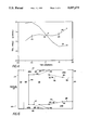
- FIG. 4 is a graph of simulated representative roll angle as a function of yaw angle for a conventional subambient slider and for a slider according to a preferred embodiment of the invention.
- FIG. 5 is a bottom view of the slider of FIG. 2 flying at a negative yaw angle, shown looking through a "transparent" disk.
- FIG. 6 is a bottom view of a preferred subambient pressure slider according to the present invention.
- FIGS. 7, 8 are a side view and trailing edge view, respectively, of the slider of FIG. 6, not to scale.
- FIG. 9a relates the pressure profile for an inner rail or outer rail to the rail configuration in a prior art slider.
- FIG. 9b relates to the pressure profile for an inner rail or outer rail to the rail configuration in a slider according to the present invention.
- FIG. 10 shows the slider of FIG. 6 oriented parallel to the direction of air flow.
- FIG. 11 shows an upward facing slider in three different orientations (positive, zero and negative yaw) relative to a disk, where the air bearing surface of the slider is shown looking through a "transparent" disk.
- FIG. 12 is a graph of a simulated pressure profile at the bottom of a slider according to the preferred embodiment at zero yaw angle.
- FIGS. 13-15 are alternative configurations of the slider of FIG. 6.
- a typical disk storage device 10 includes a disk 12 having a surface 14 which extends from an inner radius 16 to an outer radius 18, with a multiplicity of recording tracks 17 defined on surface 14.
- a read/write head (not shown) is typically located on a slider 20 along trailing edge 99 facing surface 14.
- Slider 20 is mounted on a positioning arm/suspension assembly 22. Arm 22 is connected to and driven by a rotary actuator 24 capable of positioning slider 20 at any point along an arc 25 extending from inner radius 16 to outer radius 18.
- Disk 12 rotates beneath head 20 at high speed in a direction (as indicated by arrow 26).
- the longitudinal axis 29 of slider 20 is tangential to the recording track 17 at that position, with zero yaw angle.
- the slider is at a yaw angle to the tangent.
- a typical subambient pressure slider 20 has two rails 32, 34 that face the disk surface 14, and a subambient pressure cavity 36. Air flowing between the disk and slider past a leading ramp 31 and under rails 32, 34 creates relatively high pressure under the rails to lift the slider above surface 14. Air flowing through cavity 36 is intended to create a counteracting subambient pressure to draw the slider toward surface 14. The net result is that a lower external load is required to fly the slider for a given height.
- a small, relatively constant pressure difference is generated beneath rail 32 and rail 34, even when the slider is at zero yaw angle, i.e., at the tangential location 27 (FIG. 1), because of a small difference in the linear velocity of the disk at the two different locations beneath the two rails (points nearer the inner radius 16 of disk 12 have a lower linear velocity than points nearer the outer edge).
- this pressure difference between rails 32 and 34 causes slider 20 to roll slightly.
- the inner rail 34 flies closer to the disk center than does the outer rail 32, defining a "positive" natural roll angle A.
- the amount of the roll could be, e.g., 2.5 ⁇ radians, shown at point 35 on curve 50, FIG. 4, which corresponds to the zero yaw point 27 on FIG. 1. If the slider were always kept at a zero yaw angle (i.e., tangential to the disk track), this type of roll would be relatively uniform regardless of the position of slider 20 along arc 25, and thus could be compensated such as by counterweighting.
- rectangular slider 100 has a leading edge 104, a trailing edge 106, and two side edges 108, 110.
- a ramp 120 extends from leading edge 104 at an angle, for example of 50 minutes (not to scale in FIG. 7).
- a cross rail, or bridge, 122 located immediately downstream of ramp 120, joins two side rails 124, 126.
- Inner edges 130, 132 of rails 124, 126 run parallel, beginning where they connect to bridge 122 and continuing rearward to break points 136. From break points 136 to another pair of break points 140, inner edges 130, 132 define foils 195, 196 which flair inward toward each other, for example at an angle of about 15 degrees (not to scale in FIG. 6). From break points 140 foils 195, 196 extend back to trailing edge 106, and are parallel.
- Inner edges 130, 132 (including foils 195, 196), together with bridge 122, enclose a subambient pressure cavity 128.
- cavity 128 has a depth of from 200 microinches to 1000 microinches and is open along the trailing edge.
- the ramp angle will typically range at or below one degree and the flare angle will range as desired.
- Slider 100 includes a pair of chevrons 150, 152, that cut across rails 124, 126, and connect cavity 128 to the exterior of slider 100.
- Chevrons 150, 152 are located between inner edge 134 of bridge 122 and break points 136 and extend rearward at an angle from a pair of points 154 along the inner edges 130, 132, to points 156 along side 108, 110.
- chevrons 150, 152 have the same depth as cavity 128.
- chevron angles and depths may be of varied configurations.
- FIG. 9a the pressure gradient under an example prior art rail 72 is shown (along line A--A) where dotted lines 184, 185, 186 relate local minima and local maxima of pressure gradient curve 180 to the configuration of rail 72.
- FIG. 9b the expected pressure gradient under rail 126 (along line B--B) in practice of the present invention has been approximated, where dotted lines 187, 188, and 189 relate local minima and local maxima of pressure gradient curve 190 to the configuration of rail 126.
- FIG. 9b demonstrates our belief that an entirely different gradient buildup is experienced compared to the prior art configuration of FIG. 9a. To wit: curve 190 peaks at about the beginning of cavity 128 (point X) and is relieved down to about atmospheric level or lower at chevron 152. Thereafter, the pressure gradient peaks again at point Y near the trailing edge of slider 100.
- FIGS. 10 and 11 together show slider 100 in the positive, zero and negative yaw conditions, where it can be seen that as slider 100 yaws, not only is foil 195 or 196 presented to air flow 101, but also the now leading outside edge 108 or 110 is presented as an oblique edge. It is possible that the resultant interaction of the air flow at both the inner foil 195 or 196 and outer foil 108 or 110 (or possibly at post-chevron foils 108b or 110b) contributes to the result of the invention.
- foil 195 is essentially turned away from air flow 101, although outer foil 108 (or 108b) on rail 124 is presented to air flow 101. It is speculated that the cross-sectional area of foil 196 presented to air flow 101 should be greater than that presented by foil 108b, thus resulting in the desired gradient at rail 126, such as seen in FIG. 11.
- FIG. 12 is a graph of a simulated pressure profile at the bottom of a slider according to the preferred embodiment at zero yaw angle.
- FIGS. 13-15 Alternative embodiments of the invention are shown in FIGS. 13-15, where rails 124, 126 assume tapered in (FIG. 13), fully parallel and not tapered (FIG. 14), and not parallel and not tapered (FIG. 15) orientations.
- at least one chevron 150, 152 can be provided in at least one rail 124 or 126 at any suitable location in accordance with the invention.
- optimum configuration of a slider in practice of the present invention will depend upon desired application, e.g., for a given arm, disk, slider, radius and yaw relation, and speed, for example.
Abstract
Description
Claims (13)
Priority Applications (2)
| Application Number | Priority Date | Filing Date | Title |
|---|---|---|---|
| US07/663,192 US5097370A (en) | 1989-03-17 | 1991-02-28 | Subambient pressure air bearing slider for disk drive |
| US07/851,054 US5309303A (en) | 1989-03-17 | 1992-03-13 | Subambient pressure air bearing slider for disk drive |
Applications Claiming Priority (2)
| Application Number | Priority Date | Filing Date | Title |
|---|---|---|---|
| US32522289A | 1989-03-17 | 1989-03-17 | |
| US07/663,192 US5097370A (en) | 1989-03-17 | 1991-02-28 | Subambient pressure air bearing slider for disk drive |
Related Parent Applications (1)
| Application Number | Title | Priority Date | Filing Date |
|---|---|---|---|
| US32522289A Continuation | 1989-03-17 | 1989-03-17 |
Related Child Applications (1)
| Application Number | Title | Priority Date | Filing Date |
|---|---|---|---|
| US07/851,054 Continuation-In-Part US5309303A (en) | 1989-03-17 | 1992-03-13 | Subambient pressure air bearing slider for disk drive |
Publications (1)
| Publication Number | Publication Date |
|---|---|
| US5097370A true US5097370A (en) | 1992-03-17 |
Family
ID=26984829
Family Applications (2)
| Application Number | Title | Priority Date | Filing Date |
|---|---|---|---|
| US07/663,192 Expired - Lifetime US5097370A (en) | 1989-03-17 | 1991-02-28 | Subambient pressure air bearing slider for disk drive |
| US07/851,054 Expired - Lifetime US5309303A (en) | 1989-03-17 | 1992-03-13 | Subambient pressure air bearing slider for disk drive |
Family Applications After (1)
| Application Number | Title | Priority Date | Filing Date |
|---|---|---|---|
| US07/851,054 Expired - Lifetime US5309303A (en) | 1989-03-17 | 1992-03-13 | Subambient pressure air bearing slider for disk drive |
Country Status (1)
| Country | Link |
|---|---|
| US (2) | US5097370A (en) |
Cited By (35)
| Publication number | Priority date | Publication date | Assignee | Title |
|---|---|---|---|---|
| US5196974A (en) * | 1990-01-22 | 1993-03-23 | Hitachi, Ltd. | Rail-type floating magnetic head slider |
| US5200868A (en) * | 1990-05-25 | 1993-04-06 | Seagate Technology, Inc. | Negative pressure air bearing slider having an air bearing surface trailing a negative pressure cavity |
| US5287235A (en) * | 1991-10-28 | 1994-02-15 | International Business Machines Corporation | Slider air bearing surface with angled rail configuration |
| DE4342079A1 (en) * | 1992-12-09 | 1994-06-16 | Hitachi Ltd | Hard disc drive for computer - has angled slots across head face to expel lubricant radially outwards from disc centre |
| US5343343A (en) * | 1990-05-25 | 1994-08-30 | Seagate Technology, Inc. | Air bearing slider with relieved rail ends |
| US5396386A (en) * | 1993-05-28 | 1995-03-07 | International Business Machines Corporation | Roll insensitive air bearing slider |
| US5420735A (en) * | 1993-05-28 | 1995-05-30 | Maxtor Corporation | Hard disk drive having partial contact magnetic recording slider apparatus |
| US5636086A (en) * | 1993-05-28 | 1997-06-03 | International Business Machines Corporation | Roll insensitive air bearing slider |
| US5654853A (en) * | 1994-02-04 | 1997-08-05 | Seagate Technology, Inc. | Disc storage device having a magnetic head air bearing slider configuration for reduced disc overhead |
| US5677812A (en) * | 1996-01-26 | 1997-10-14 | Samsung Electronics, North America | Air bearing slider with variable sub-ambient pressure control |
| US5724212A (en) * | 1995-05-26 | 1998-03-03 | Quantum Corporation | Method and apparatus for increasing data density in magnetic data storage disk drives |
| US5831791A (en) * | 1996-03-27 | 1998-11-03 | Headway Technologies, Inc. | Negative Pressure air bearing slider having transition region between positive and negative pressure regions |
| US5914833A (en) * | 1995-03-07 | 1999-06-22 | Sony Corporation | Floating type head slider, floating type head device, and disc drive |
| US5973881A (en) * | 1997-03-14 | 1999-10-26 | Nec Corporation | Magnetic head slider with rail grooves narrowing from base thereof |
| US6034842A (en) * | 1996-08-30 | 2000-03-07 | Sae Magnetics (H.K.) Ltd. | Subambient pressure slider for constant flying height |
| US6064529A (en) * | 1998-07-02 | 2000-05-16 | Optiteck, Inc. | Spherical aberration correction using flying lens and method |
| US6262970B1 (en) * | 1999-03-17 | 2001-07-17 | Seagate Technology Llc | Air bearing surface design for glide testing of plastic media |
| US6417994B1 (en) | 1999-04-22 | 2002-07-09 | Samsung Electronics, Co., Ltd. | Swage plate with protruded walls to increase retention torque in hard disk applications |
| US6417986B1 (en) | 1998-11-16 | 2002-07-09 | Samsung Electronics Co., Ltd. | Impact guard for limiting hard disk movement |
| US6443813B1 (en) | 2000-04-12 | 2002-09-03 | Seagate Technology Llc | Process of eliminating ridges formed during dicing of aerodynamic sliders, and sliders formed thereby |
| US20020155216A1 (en) * | 2001-04-19 | 2002-10-24 | Reitz John Bradford | Spin coated media |
| US6501614B1 (en) | 1999-08-19 | 2002-12-31 | Samsung Electronics Co., Ltd. | Acoustic insulator for controlling noise generated in a mass storage device |
| US6549372B1 (en) | 1998-12-15 | 2003-04-15 | Samsung Electronics Co., Ltd | Device for limiting head movement within a hard disk drive |
| US6590738B2 (en) | 2001-03-01 | 2003-07-08 | Samsung Electronics Co., Ltd. | Particle removal device in a hard disk drive |
| US6661612B1 (en) * | 2001-10-21 | 2003-12-09 | Western Digital Technologies, Inc. | Air bearing slider including side rail shallow recessed surfaces extending along trailing portions of leading side air bearing surfaces |
| US6704161B1 (en) | 1998-11-06 | 2004-03-09 | Samsung Electronics Co. Ltd. | Shock protection skin bumper for a hard disk drive |
| US6715200B2 (en) | 1999-02-12 | 2004-04-06 | General Electric Company | Methods for making data storage media |
| US6744597B2 (en) | 1999-10-29 | 2004-06-01 | Samsung Electronics Co., Ltd. | Dynamic absorber for an actuator arm in a disk drive |
| US6744599B1 (en) * | 2002-04-30 | 2004-06-01 | Western Digital Technologies, Inc. | Air bearing slider with an angularly disposed channel formed between a side rail and a leading side air bearing surface |
| US6762908B2 (en) | 2001-06-18 | 2004-07-13 | Samsung Electronics Co., Ltd. | Air razor and disk limiter for a hard disk drive |
| US6947252B2 (en) | 2000-05-10 | 2005-09-20 | Samsung Electronics Co., Ltd. | Wave stringer for controlling acoustic noise and shock vibration in a storage device |
| US20050237668A1 (en) * | 2004-04-21 | 2005-10-27 | Cha Ellis T | Air-bearing design with particle rejection features |
| US20070190907A1 (en) * | 2006-02-13 | 2007-08-16 | Ahead Magnetics, Inc. | Burnishing head |
| US20080117549A1 (en) * | 2006-11-16 | 2008-05-22 | Weidong Huang | Reducing the probability of a slider contacting a surface of a disk |
| US20080304182A1 (en) * | 2007-06-11 | 2008-12-11 | Samsung Electronics Co., Ltd. | Head slider and hard disk drive having the same |
Families Citing this family (30)
| Publication number | Priority date | Publication date | Assignee | Title |
|---|---|---|---|---|
| US6021024A (en) * | 1992-02-21 | 2000-02-01 | Kabushiki Kaisha Toshiba | Magnetic disk drive having a constant skew angle |
| US5438467A (en) * | 1992-10-28 | 1995-08-01 | International Business Machines Corporation | Negative pressure air bearing design |
| US5418667A (en) * | 1993-08-03 | 1995-05-23 | International Business Machines Corporation | Slider with transverse ridge sections supporting air-bearing pads and disk drive incorporating the slider |
| US5423207A (en) * | 1993-12-27 | 1995-06-13 | International Business Machines Corporation | Advanced PZT glide head design and implementation for a small slider |
| US5450747A (en) * | 1993-12-27 | 1995-09-19 | International Business Machines Corporation | Method for optimizing piezoelectric surface asperity detection sensor |
| US6760193B1 (en) * | 1995-04-07 | 2004-07-06 | Hitachi Global Storage Technologies Japan, Ltd. | Magnetic head gimbal assembly and magnetic disk unit |
| JPH08279265A (en) * | 1995-04-07 | 1996-10-22 | Fujitsu Ltd | Magnetic head slider |
| US5537034A (en) * | 1995-05-19 | 1996-07-16 | Quantum Corporation | Method for mapping thermal asperities of a magnetic recording surface in data storage device |
| US5815346A (en) * | 1995-06-12 | 1998-09-29 | Maxtor Corporation | Textured slider surface |
| US5889634A (en) * | 1995-12-18 | 1999-03-30 | Read-Rite Corporation | Reduced-altitude-sensitive subambient pressure air bearing slider |
| US5825587A (en) | 1996-03-01 | 1998-10-20 | International Business Machines Corporation | Shallow etch air bearing surface features for optimized transducer spacing |
| US5796550A (en) * | 1996-10-16 | 1998-08-18 | International Business Machines Corporation | Method and apparatus for providing diverging rail edge geometry for air bearing slider |
| US6004472A (en) * | 1997-05-14 | 1999-12-21 | International Business Machines Corporation | Dual etch step process for making a three etch depth air bearing slider |
| US6055128A (en) * | 1997-05-14 | 2000-04-25 | International Business Machines Corporation | Dual etch step pad air bearing design with three etch depths |
| JPH11353774A (en) * | 1998-06-11 | 1999-12-24 | Mitsumi Electric Co Ltd | Magnetic head |
| US6014306A (en) * | 1998-09-24 | 2000-01-11 | Hubbell Incorporated | Electrical device with wedge insert gas seal for probe |
| JP3674347B2 (en) | 1998-09-28 | 2005-07-20 | 富士通株式会社 | Negative pressure head slider |
| JP3264895B2 (en) | 1999-01-12 | 2002-03-11 | 富士通株式会社 | Flying head slider and manufacturing method thereof |
| JP2001344724A (en) * | 2000-06-01 | 2001-12-14 | Fujitsu Ltd | Floating head slider |
| US6446517B1 (en) | 2000-11-20 | 2002-09-10 | Samsung Electronics Company | Controlled particle deposition in drives and on media for thermal asperity studies |
| US6501621B1 (en) | 2000-11-22 | 2002-12-31 | Matsushita Kotobuki Electronics Peripherals Of America, Inc. | Air bearing slider having improved take-off velocity |
| US6646831B1 (en) | 2000-11-22 | 2003-11-11 | Matsushita Kotobuki Electronics Peripherals Of America, Inc. | Air bearing slider having optimized etch depth ratio |
| US7159228B2 (en) * | 2001-12-12 | 2007-01-02 | Matsushita Electric Industrial Co., Ltd. | Converter support device with slider |
| KR100524940B1 (en) | 2003-02-07 | 2005-10-31 | 삼성전자주식회사 | Air bearing slider for disc drive |
| US7251107B2 (en) * | 2004-07-30 | 2007-07-31 | Hitachi Global Storage Technologies Netherlands B.V. | Method and apparatus for providing an air bearing pad having improved roll angle sigma |
| US7230797B1 (en) * | 2004-10-08 | 2007-06-12 | Seagate Technology, Llc | Slider having transversely separated bearing surfaces and openings to rear bearing surfaces |
| JP4041507B2 (en) * | 2005-05-26 | 2008-01-30 | アルプス電気株式会社 | Magnetic head slider |
| US8009389B2 (en) * | 2006-07-28 | 2011-08-30 | Hitachi Global Storage Technologies, Netherlands B.V. | Air bearing with low crown sensitivity through side channels |
| US8164860B1 (en) | 2010-10-20 | 2012-04-24 | Hitachi Global Storage Technologies Netherlands B.V. | Servo write robust and good altitude performance ABS |
| US9093098B2 (en) * | 2012-12-07 | 2015-07-28 | Seagate Technology Llc | Slider with shock damping features |
Citations (7)
| Publication number | Priority date | Publication date | Assignee | Title |
|---|---|---|---|---|
| US3855625A (en) * | 1973-12-19 | 1974-12-17 | Ibm | Magnetic head slider assembly |
| US4218715A (en) * | 1979-03-12 | 1980-08-19 | International Business Machines Corporation | Magnetic head slider assembly |
| US4420780A (en) * | 1981-08-17 | 1983-12-13 | International Business Machines | Self-loading magnetic head air bearing slider |
| US4475135A (en) * | 1981-10-07 | 1984-10-02 | International Business Machines | Magnetic head air bearing slider |
| US4553184A (en) * | 1981-07-31 | 1985-11-12 | Tokyo Shibaura Denki Kabushiki Kaisha | Magnetic head slider |
| US4555739A (en) * | 1982-11-26 | 1985-11-26 | International Business Machines Corporation | Semi self-loading ferrite head |
| US4802042A (en) * | 1987-02-05 | 1989-01-31 | Magnetic Peripherals Inc. | Side-vented magnetic head air bearing slider |
Family Cites Families (5)
| Publication number | Priority date | Publication date | Assignee | Title |
|---|---|---|---|---|
| EP0076361B1 (en) * | 1981-10-07 | 1986-01-29 | International Business Machines Corporation | Air bearing slider for a transducer |
| JPS60109073A (en) * | 1983-11-17 | 1985-06-14 | Fujitsu Ltd | Slider for magnetic head |
| US4894740A (en) * | 1988-09-28 | 1990-01-16 | International Business Machines Corporation | Magnetic head air bearing slider |
| CA1323421C (en) * | 1989-03-17 | 1993-10-19 | Yiao-Tee Hsia | Disc drive slider configured to counteract roll |
| US5200868A (en) * | 1990-05-25 | 1993-04-06 | Seagate Technology, Inc. | Negative pressure air bearing slider having an air bearing surface trailing a negative pressure cavity |
-
1991
- 1991-02-28 US US07/663,192 patent/US5097370A/en not_active Expired - Lifetime
-
1992
- 1992-03-13 US US07/851,054 patent/US5309303A/en not_active Expired - Lifetime
Patent Citations (7)
| Publication number | Priority date | Publication date | Assignee | Title |
|---|---|---|---|---|
| US3855625A (en) * | 1973-12-19 | 1974-12-17 | Ibm | Magnetic head slider assembly |
| US4218715A (en) * | 1979-03-12 | 1980-08-19 | International Business Machines Corporation | Magnetic head slider assembly |
| US4553184A (en) * | 1981-07-31 | 1985-11-12 | Tokyo Shibaura Denki Kabushiki Kaisha | Magnetic head slider |
| US4420780A (en) * | 1981-08-17 | 1983-12-13 | International Business Machines | Self-loading magnetic head air bearing slider |
| US4475135A (en) * | 1981-10-07 | 1984-10-02 | International Business Machines | Magnetic head air bearing slider |
| US4555739A (en) * | 1982-11-26 | 1985-11-26 | International Business Machines Corporation | Semi self-loading ferrite head |
| US4802042A (en) * | 1987-02-05 | 1989-01-31 | Magnetic Peripherals Inc. | Side-vented magnetic head air bearing slider |
Non-Patent Citations (4)
| Title |
|---|
| IBM T.D.B., vol. 27, No. 10A, 3/85; `Magnetic Disk Storage Sys. with Structured Magnetic Head Slider`, pp. 5820-5821. |
| IBM T.D.B., vol. 27, No. 10A, 3/85; Magnetic Disk Storage Sys. with Structured Magnetic Head Slider , pp. 5820 5821. * |
| Tagama, "Optimum Design Consideration for Air-Lubricated Slider Bearings of Film Head", N.E.C. Research and Development, 68:90-100 (1983). |
| Tagama, Optimum Design Consideration for Air Lubricated Slider Bearings of Film Head , N.E.C. Research and Development, 68:90 100 (1983). * |
Cited By (45)
| Publication number | Priority date | Publication date | Assignee | Title |
|---|---|---|---|---|
| US5196974A (en) * | 1990-01-22 | 1993-03-23 | Hitachi, Ltd. | Rail-type floating magnetic head slider |
| USRE35800E (en) * | 1990-05-25 | 1998-05-19 | Seagate Technology, Inc. | Air bearing slider with relieved rail ends |
| US5200868A (en) * | 1990-05-25 | 1993-04-06 | Seagate Technology, Inc. | Negative pressure air bearing slider having an air bearing surface trailing a negative pressure cavity |
| US5343343A (en) * | 1990-05-25 | 1994-08-30 | Seagate Technology, Inc. | Air bearing slider with relieved rail ends |
| US5287235A (en) * | 1991-10-28 | 1994-02-15 | International Business Machines Corporation | Slider air bearing surface with angled rail configuration |
| DE4342079A1 (en) * | 1992-12-09 | 1994-06-16 | Hitachi Ltd | Hard disc drive for computer - has angled slots across head face to expel lubricant radially outwards from disc centre |
| US5737151A (en) * | 1993-05-28 | 1998-04-07 | International Business Machines Corporation | Roll insensitive air bearing slider |
| US5650893A (en) * | 1993-05-28 | 1997-07-22 | International Business Machines Corporation | Roll insensitive air bearing slider |
| US5396386A (en) * | 1993-05-28 | 1995-03-07 | International Business Machines Corporation | Roll insensitive air bearing slider |
| US5420735A (en) * | 1993-05-28 | 1995-05-30 | Maxtor Corporation | Hard disk drive having partial contact magnetic recording slider apparatus |
| US5636086A (en) * | 1993-05-28 | 1997-06-03 | International Business Machines Corporation | Roll insensitive air bearing slider |
| US5923499A (en) * | 1994-02-04 | 1999-07-13 | Seagate Technology, Inc. | Air bearing slider having shaped air bearing surface extending portion located on central axis |
| US5654853A (en) * | 1994-02-04 | 1997-08-05 | Seagate Technology, Inc. | Disc storage device having a magnetic head air bearing slider configuration for reduced disc overhead |
| US5914833A (en) * | 1995-03-07 | 1999-06-22 | Sony Corporation | Floating type head slider, floating type head device, and disc drive |
| US5724212A (en) * | 1995-05-26 | 1998-03-03 | Quantum Corporation | Method and apparatus for increasing data density in magnetic data storage disk drives |
| US5677812A (en) * | 1996-01-26 | 1997-10-14 | Samsung Electronics, North America | Air bearing slider with variable sub-ambient pressure control |
| US5949614A (en) * | 1996-03-27 | 1999-09-07 | Headway Technologies, Inc. | Adjustable negative pressure air bearing slider |
| US5831791A (en) * | 1996-03-27 | 1998-11-03 | Headway Technologies, Inc. | Negative Pressure air bearing slider having transition region between positive and negative pressure regions |
| US6034842A (en) * | 1996-08-30 | 2000-03-07 | Sae Magnetics (H.K.) Ltd. | Subambient pressure slider for constant flying height |
| US5973881A (en) * | 1997-03-14 | 1999-10-26 | Nec Corporation | Magnetic head slider with rail grooves narrowing from base thereof |
| US6064529A (en) * | 1998-07-02 | 2000-05-16 | Optiteck, Inc. | Spherical aberration correction using flying lens and method |
| US6704161B1 (en) | 1998-11-06 | 2004-03-09 | Samsung Electronics Co. Ltd. | Shock protection skin bumper for a hard disk drive |
| US6417986B1 (en) | 1998-11-16 | 2002-07-09 | Samsung Electronics Co., Ltd. | Impact guard for limiting hard disk movement |
| US6549372B1 (en) | 1998-12-15 | 2003-04-15 | Samsung Electronics Co., Ltd | Device for limiting head movement within a hard disk drive |
| US6752952B2 (en) | 1999-02-12 | 2004-06-22 | General Electric Company | Embossing methods |
| US6715200B2 (en) | 1999-02-12 | 2004-04-06 | General Electric Company | Methods for making data storage media |
| US6262970B1 (en) * | 1999-03-17 | 2001-07-17 | Seagate Technology Llc | Air bearing surface design for glide testing of plastic media |
| US6417994B1 (en) | 1999-04-22 | 2002-07-09 | Samsung Electronics, Co., Ltd. | Swage plate with protruded walls to increase retention torque in hard disk applications |
| US6501614B1 (en) | 1999-08-19 | 2002-12-31 | Samsung Electronics Co., Ltd. | Acoustic insulator for controlling noise generated in a mass storage device |
| US6744597B2 (en) | 1999-10-29 | 2004-06-01 | Samsung Electronics Co., Ltd. | Dynamic absorber for an actuator arm in a disk drive |
| US6443813B1 (en) | 2000-04-12 | 2002-09-03 | Seagate Technology Llc | Process of eliminating ridges formed during dicing of aerodynamic sliders, and sliders formed thereby |
| US6947252B2 (en) | 2000-05-10 | 2005-09-20 | Samsung Electronics Co., Ltd. | Wave stringer for controlling acoustic noise and shock vibration in a storage device |
| US6590738B2 (en) | 2001-03-01 | 2003-07-08 | Samsung Electronics Co., Ltd. | Particle removal device in a hard disk drive |
| US20020155216A1 (en) * | 2001-04-19 | 2002-10-24 | Reitz John Bradford | Spin coated media |
| US6762908B2 (en) | 2001-06-18 | 2004-07-13 | Samsung Electronics Co., Ltd. | Air razor and disk limiter for a hard disk drive |
| US6661612B1 (en) * | 2001-10-21 | 2003-12-09 | Western Digital Technologies, Inc. | Air bearing slider including side rail shallow recessed surfaces extending along trailing portions of leading side air bearing surfaces |
| US6744599B1 (en) * | 2002-04-30 | 2004-06-01 | Western Digital Technologies, Inc. | Air bearing slider with an angularly disposed channel formed between a side rail and a leading side air bearing surface |
| US7760468B2 (en) * | 2004-04-21 | 2010-07-20 | Sae Magnetics (Hk) Ltd. | Air-bearing design with particle rejection features |
| US20050237668A1 (en) * | 2004-04-21 | 2005-10-27 | Cha Ellis T | Air-bearing design with particle rejection features |
| US20070190907A1 (en) * | 2006-02-13 | 2007-08-16 | Ahead Magnetics, Inc. | Burnishing head |
| US7314404B2 (en) * | 2006-02-13 | 2008-01-01 | Komag, Inc. | Burnishing head |
| US20080117549A1 (en) * | 2006-11-16 | 2008-05-22 | Weidong Huang | Reducing the probability of a slider contacting a surface of a disk |
| US8248729B2 (en) * | 2006-11-16 | 2012-08-21 | Hitachi Global Storage Technologies, Netherlands B.V. | Slider with hook-shaped air compression mechanisms near trailing edge corners |
| US20080304182A1 (en) * | 2007-06-11 | 2008-12-11 | Samsung Electronics Co., Ltd. | Head slider and hard disk drive having the same |
| US8213111B2 (en) * | 2007-06-11 | 2012-07-03 | Seagate Technology Llc | Head slider and hard disk drive having the same |
Also Published As
| Publication number | Publication date |
|---|---|
| US5309303A (en) | 1994-05-03 |
Similar Documents
| Publication | Publication Date | Title |
|---|---|---|
| US5097370A (en) | Subambient pressure air bearing slider for disk drive | |
| US5062017A (en) | Hour-glass disk head slider | |
| EP0387444B1 (en) | Subambient pressure air bearing | |
| US4734803A (en) | Magnetic head air bearing slider | |
| US5359480A (en) | Magnetic head air bearing slider | |
| US6937440B2 (en) | Head slider having convergent channel features with side opening | |
| US5424888A (en) | Speed independent, air bearing slider | |
| US3855625A (en) | Magnetic head slider assembly | |
| US6147838A (en) | Air bearing slider with shaped taper | |
| US6515831B1 (en) | Disc head slider having leading and trailing channeled rails for enhanced damping | |
| US6747847B2 (en) | Self-flushing trench air bearing for improved slider flyability | |
| US8184405B1 (en) | Air-bearing slider design for sub-nanometer clearance in hard disk drive (HDD) | |
| US6122147A (en) | Negative pressure head contour in a linear tape recording system with tape deforming cavity | |
| US5353180A (en) | Air bearing magnetic slider with wishbone-shaped rails | |
| US20040120075A1 (en) | Center split feature and pressurization for altitude insensitivity, high pitch torque and high preload sensitivity air bearing slider | |
| US5568981A (en) | Negative pressure air bearing slider | |
| US6072662A (en) | Magnetic head slider with U-shaped and/or V-shaped portions | |
| US5606476A (en) | Altitude insensitive air bearing slider | |
| US5726831A (en) | Methods for operating a gas bearing slider | |
| US6678119B1 (en) | Disc head slider having rails with enclosed depressions | |
| US5128821A (en) | Flying head slider and magnetic disk unit employing same | |
| US5704715A (en) | Altitude insensitive air bearing slider | |
| US5685645A (en) | Roll balance sub-ambient pressure air bearing slider | |
| US5889637A (en) | Air bearing magnetic head slider | |
| US5889634A (en) | Reduced-altitude-sensitive subambient pressure air bearing slider |
Legal Events
| Date | Code | Title | Description |
|---|---|---|---|
| STCF | Information on status: patent grant |
Free format text: PATENTED CASE |
|
| CC | Certificate of correction | ||
| AS | Assignment |
Owner name: QUANTUM CORPORATION, CALIFORNIA Free format text: ASSIGNMENT OF ASSIGNORS INTEREST;ASSIGNOR:DIGITAL EQUIPMENT CORPORATION;REEL/FRAME:007166/0018 Effective date: 19941003 Owner name: QUANTUM CORPORATION Free format text: ASSIGNMENT OF ASSIGNORS INTEREST;ASSIGNOR:DIGITAL EQUIPMENT CORPORATION;REEL/FRAME:007156/0665 Effective date: 19941003 Owner name: CANADIAN IMPERIAL BANK OF COMMERCE, AS ADMINIST Free format text: SECURITY INTEREST;ASSIGNOR:QUANTUM CORPORATION;REEL/FRAME:007152/0815 Effective date: 19941003 |
|
| FEPP | Fee payment procedure |
Free format text: PAYOR NUMBER ASSIGNED (ORIGINAL EVENT CODE: ASPN); ENTITY STATUS OF PATENT OWNER: LARGE ENTITY |
|
| FPAY | Fee payment |
Year of fee payment: 4 |
|
| AS | Assignment |
Owner name: QUANTUM CORPORATION, CALIFORNIA Free format text: RELEASE OF PATENT SECURITY INTEREST AND REASSIGNMENT OF PATENTS AND PATENT APPLICATIONS;ASSIGNOR:CANADIAN IMPERIAL BANK OF COMMERCE;REEL/FRAME:008604/0218 Effective date: 19970516 |
|
| AS | Assignment |
Owner name: MKE-QUANTUM COMPONENTS COLORADO LCC, COLORADO Free format text: ASSIGNMENT OF ASSIGNORS INTEREST;ASSIGNOR:QUANTUM CORP.;REEL/FRAME:008595/0410 Effective date: 19970516 |
|
| AS | Assignment |
Owner name: CANADIAN IMPERIAL BANK, AS ADMINISTRATIVE AGENT, N Free format text: RELEASE;ASSIGNOR:QUANTUM CORPORATION;REEL/FRAME:008744/0904 Effective date: 19970818 |
|
| REMI | Maintenance fee reminder mailed | ||
| AS | Assignment |
Owner name: MATSUSHITA-KOTOBUKI ELECTRONICS INDUSTRIES, LTD., Free format text: ASSIGNMENT OF ASSIGNORS INTEREST;ASSIGNORS:QUANTUM CORPORATION;MATSUSHITA-KOTOBUKI PERIPHERALS CORPORATION;MKE-QUANTUM COMPONENTS LLC;AND OTHERS;REEL/FRAME:010579/0655;SIGNING DATES FROM 20000117 TO 20000127 |
|
| FPAY | Fee payment |
Year of fee payment: 8 |
|
| SULP | Surcharge for late payment | ||
| FPAY | Fee payment |
Year of fee payment: 12 |
|
| AS | Assignment |
Owner name: HERCULES TECHNOLOGY GROWTH CAPITAL, INC., CALIFORN Free format text: SECURITY AGREEMENT;ASSIGNOR:ADVANCED MICROSENSORS CORPORATION;REEL/FRAME:031694/0152 Effective date: 20130508 |