US5038258A - Illuminating arrangement for illuminating an object with incident light - Google Patents
Illuminating arrangement for illuminating an object with incident light Download PDFInfo
- Publication number
- US5038258A US5038258A US07/484,890 US48489090A US5038258A US 5038258 A US5038258 A US 5038258A US 48489090 A US48489090 A US 48489090A US 5038258 A US5038258 A US 5038258A
- Authority
- US
- United States
- Prior art keywords
- light
- light sources
- illuminating
- arrangement
- illuminating arrangement
- Prior art date
- Legal status (The legal status is an assumption and is not a legal conclusion. Google has not performed a legal analysis and makes no representation as to the accuracy of the status listed.)
- Expired - Lifetime
Links
- 238000012545 processing Methods 0.000 claims abstract description 26
- 238000003384 imaging method Methods 0.000 claims abstract description 19
- 230000003287 optical effect Effects 0.000 claims description 57
- 238000005259 measurement Methods 0.000 claims description 9
- 229910052736 halogen Inorganic materials 0.000 claims description 6
- 150000002367 halogens Chemical class 0.000 claims description 6
- 230000006978 adaptation Effects 0.000 claims 1
- 238000005286 illumination Methods 0.000 abstract description 46
- 239000000523 sample Substances 0.000 description 19
- 239000004020 conductor Substances 0.000 description 15
- 239000000463 material Substances 0.000 description 10
- 230000003595 spectral effect Effects 0.000 description 8
- 230000005855 radiation Effects 0.000 description 6
- 230000008859 change Effects 0.000 description 5
- 238000000034 method Methods 0.000 description 5
- 238000003825 pressing Methods 0.000 description 5
- 239000011796 hollow space material Substances 0.000 description 4
- 230000008901 benefit Effects 0.000 description 3
- 238000004020 luminiscence type Methods 0.000 description 3
- 230000008569 process Effects 0.000 description 3
- 229910000831 Steel Inorganic materials 0.000 description 2
- 230000015572 biosynthetic process Effects 0.000 description 2
- 230000000694 effects Effects 0.000 description 2
- 238000004519 manufacturing process Methods 0.000 description 2
- 239000010959 steel Substances 0.000 description 2
- 238000003860 storage Methods 0.000 description 2
- 230000004913 activation Effects 0.000 description 1
- 238000003491 array Methods 0.000 description 1
- 230000005540 biological transmission Effects 0.000 description 1
- 239000012876 carrier material Substances 0.000 description 1
- 238000003708 edge detection Methods 0.000 description 1
- 230000007613 environmental effect Effects 0.000 description 1
- 238000011156 evaluation Methods 0.000 description 1
- 230000006870 function Effects 0.000 description 1
- 239000011521 glass Substances 0.000 description 1
- 239000003365 glass fiber Substances 0.000 description 1
- 230000005415 magnetization Effects 0.000 description 1
- 239000011159 matrix material Substances 0.000 description 1
- 238000012986 modification Methods 0.000 description 1
- 230000004048 modification Effects 0.000 description 1
- 230000001095 motoneuron effect Effects 0.000 description 1
- 230000010287 polarization Effects 0.000 description 1
- 230000002787 reinforcement Effects 0.000 description 1
- 230000000717 retained effect Effects 0.000 description 1
- 239000004065 semiconductor Substances 0.000 description 1
- 239000007779 soft material Substances 0.000 description 1
- 239000007787 solid Substances 0.000 description 1
- 239000000758 substrate Substances 0.000 description 1
- 230000001960 triggered effect Effects 0.000 description 1
- 238000009423 ventilation Methods 0.000 description 1
- 238000004804 winding Methods 0.000 description 1
Images


Classifications
-
- G—PHYSICS
- G02—OPTICS
- G02B—OPTICAL ELEMENTS, SYSTEMS OR APPARATUS
- G02B25/00—Eyepieces; Magnifying glasses
- G02B25/02—Eyepieces; Magnifying glasses with means for illuminating object viewed
-
- G—PHYSICS
- G01—MEASURING; TESTING
- G01B—MEASURING LENGTH, THICKNESS OR SIMILAR LINEAR DIMENSIONS; MEASURING ANGLES; MEASURING AREAS; MEASURING IRREGULARITIES OF SURFACES OR CONTOURS
- G01B11/00—Measuring arrangements characterised by the use of optical techniques
-
- G—PHYSICS
- G01—MEASURING; TESTING
- G01J—MEASUREMENT OF INTENSITY, VELOCITY, SPECTRAL CONTENT, POLARISATION, PHASE OR PULSE CHARACTERISTICS OF INFRARED, VISIBLE OR ULTRAVIOLET LIGHT; COLORIMETRY; RADIATION PYROMETRY
- G01J3/00—Spectrometry; Spectrophotometry; Monochromators; Measuring colours
- G01J3/02—Details
- G01J3/10—Arrangements of light sources specially adapted for spectrometry or colorimetry
-
- G—PHYSICS
- G02—OPTICS
- G02B—OPTICAL ELEMENTS, SYSTEMS OR APPARATUS
- G02B21/00—Microscopes
- G02B21/06—Means for illuminating specimens
- G02B21/08—Condensers
- G02B21/082—Condensers for incident illumination only
Definitions
- the invention relates to an arrangement for illuminating an object with incident light which includes a plurality of individual light sources and which requires no mechanical adjusting elements for a viewing device.
- the illumination at an angle of incidence leads to the formation of shadows and thereby significantly increases contrast during viewing.
- German Patent 28 52 203 discloses an illuminating arrangement which includes a planar holding ring having light conductor end faces with the holding ring being disposed in the tube of the objective symmetrically about the optical axis in an outer annular region. Light from the end faces of the light conductors exits therefrom parallel to the optical axis.
- This holding ring is displaceable in the tube so that the angle of incidence of the light can be changed by a movement of the holding ring.
- it is a disadvantage it is necessary to mechanically adjust the holding ring in order to obtain a change in the irradiation angle.
- the inner arrangement of the light conductor end faces makes it necessary to provide a very large ocular lens and furthermore leads to stray light in the tube. The use of many light conductors is also disturbing. These conductors must be brought in from the outside and their ends have to be precisely machined.
- a ring-shaped illuminator for an ophthalmometer is disclosed in U.S. Pat. No. 4,666,269.
- a cylinder lens is provided which is made up of several concentric rings and has a plurality of circularly-shaped openings at its rearward end in the rearward focus.
- the ophthalmometer further includes a light source which can comprise a plurality of small light sources and the light of the light source is directed by the cylinder lens in parallel rays onto an eye with the center point rays meeting at a point on the optical axis. It is a disadvantage of this illumination that no selection of different illuminating angles or illuminating sectors is possible since the undirected light of the light source enters the lens through fixed diaphragms.
- a multi-directional surface illuminator is disclosed in U.S. Pat. No. 4,567,551 wherein the light of each light source is deflected onto a zone plate via a mirror mounted at an angle. The mirror is arranged outside of the fitting holding the objective. The zone plate then focuses the light in a region surrounding the optical axis.
- U.S. Pat. No. 4,706,168 discloses an illuminating arrangement wherein the light of a plurality of light sources is focused parallelly to the optical axis via two reflector rings into an object plane in a region around the optical axis.
- the light sources can be also limited to sectors and are disposed in a ring around the optical axis of an objective outside of the holder holding the objective.
- a change in the illuminating angle is possible by means of a mechanical adjustment of one of the two reflector rings.
- the significant disadvantage of this arrangement is the necessity of a mechanical adjustment in order to obtain a change of the illuminating angle.
- the reflecting surfaces are complex to process and this is a further disadvantageous characteristic of this illuminating arrangement.
- the illuminating arrangement of the invention illuminates an object with incident light and is for a viewing and imaging device.
- the viewing and imaging device has an optical axis which intersects an object plane defined by the object.
- the illuminating arrangement includes: a plurality of individual light sources defining respective beam axes; a mounting structure for mounting the light sources in a geometric array defining a geometric array center coincident with the optical axis of said device and for holding the light sources so as to cause the beam axes to intersect the optical axis in the object plane; and, control means for controlling the light sources individually and in combination as to their respective intensities for a specific object.
- the light sources are arranged about the optical axis in an array which is at least two-dimensional and prevent the heat in the tube from having negative effects.
- An illumination occurs from above so that the area of application includes all three-dimensional objects independently of their transparency.
- a variable illumination of the objects with selectable angles of illumination can take place without motoric adjustment.
- the alignment of the individual light sources is such that the optical axes of the light sources intersect in a point on the optical axis of the viewing optic in the object plane. In this way, an optimal illumination of the object region taken in by the objective of the illumination apparatus is assured. This is facilitated in that the optical axis of the illuminating imaging optic passes through the geometric array center.
- illumination intensities are obtained which are selectable from all illuminating directions with freely selectable changes of the angle of incidence of the light without a mechanical adjustment since the light sources irradiate their light along different beam axes.
- a controllable illumination specific to the object is obtained for each individual light source and also for a combination of the light sources for different illuminating directions since the individual light sources in two-dimensional arrays have a different distance from the geometric array center.
- the array of the individual light sources can be advantageously configured so that several single individual or collective controllable light sources can be arranged in several concentric circles in different planes.
- the light sources can be self-luminous devices such as temperature radiators or luminescence radiators but can also include glass fibers, light-conducting rods or diaphragms illuminated from behind such as miniature halogen lamps, miniature stratoscope lamps, ultrabright light-emitting diodes and the like.
- the array of the light sources is in at least two dimensions and in this array spatial light modulators can be provided which can be driven electronically.
- These light modulators can be realized as miniature projectors and can project selectively a specific pattern onto the measurement plane or simply illuminate the scene.
- the light structures imaged onto the object can be selected specifically for the object.
- the individual light sources can be aligned ab initio in the radiation direction in order to avoid the need for an optical element for deflecting the light onto the area to be illuminated.
- a hemispherically-shaped carrier is suitable as a mounting body for this purpose and the individual light sources can be mounted on the inner surface thereof. It is advantageous if all individual light sources have the same spacing from the center of the illumination field. This makes possible that all individual light sources have the same focusing lens. In this way, a uniform spacing of the individual light sources from the luminescent field is obtained if the center point of the inner radius of the carrier lies at or near the object plane of an imaging optic connected to the illumination arrangement.
- the form of the hemispherically-shaped carrier can be an entire hemisphere, a spherical section or a spherical layer in dependence upon the desired angular range for the illumination.
- the space between the light sources can be interrupted for the purpose of ventilation and also for optical control by the service personnel whereby the light sources can then be accommodated in extension arms or in wheel-like configurations.
- the carrier material can be hard or it can be very soft. If very soft, it can be reinforced by supporting elements on the light sources and by connecting elements between the supporting elements. An additional protection against collision is provided if the material is soft. This is especially desirable when used on optical probes for coordinate measuring apparatus.
- the imaging optics have to be corrected only for this limited spectral range.
- a manual drive is achieved by an operating console connected to the illuminating arrangement.
- This operating console means for driving the light sources as well as means for indicating the light sources switched on are provided.
- the storage of the selected type of illumination takes place in a memory unit and the type of illumination is indicated on the indicating arrangement.
- the activation of the individual light sources takes place via push buttons on the front plate of the input unit.
- the push buttons are arranged on the front plate in correspondence to the light sources and control light-emitting diodes which light when the light source is switched on. Each light source can be individually set with respect to its luminescence. Additional push buttons make it possible to program different illuminating settings.
- a knowledge-based image processing unit is understood to be a unit which makes it possible to adjust the illumination of the object specifically with respect to the object. The unit achieves this either with the aid of a priori knowledge (templates) and/or by means of different algorithms (image illuminating algorithms, illuminating combination algorithms and the like) which can be alternately retrieved.
- the a priori knowledge is available to the image processing unit after a teach-in procedure or from a CAD-unit with the object scene as well as also the illumination configuration corresponding thereto being stored. If further progress by means of a template is not possible or if there are no templates present, an optimal illumination can also be obtained by means of a hierarchical search process, different image processing algorithms and illuminating adjustments (illumination intensity, illumination directions). In this way, the image processing unit achieves also a certain redundance capability so that, for example, shadow edges can be distinguished from grooves by means of a comparison of two different illuminating adjustments.
- a simple adaptability to different image processing algorithms is obtained especially by means of an arrangement of light sources and structure projectors in planes perpendicular to the optical axis.
- the light structure projectors are especially suitable also to the assembly of an active automatic focusing arrangement.
- at least two light projectors are necessary which can be disposed opposite each other in the same plane perpendicular to the optical axis of the viewing optics.
- This automatic focusing arrangement a precise z-guide variable for the z-actuator is obtained. This is especially important when using the illumination arrangement in a measuring apparatus having an optical probe head.
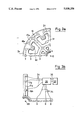
- FIG. 1 is a side elevation view, partially in section, of a ring-shaped illuminating arrangement utilizing a hemispherically-shaped carrier body on a microscope tube or on an optical probe head for a coordinate measuring apparatus;
- FIG. 2a is a detail view showing the mounting of a miniature lamp such as a halogen lamp
- FIG. 2b is a detail view of an embodiment wherein a light conductor is substituted for the miniature lamp
- FIG. 3a is a plan view showing a portion of the illuminating arrangement of FIG. 1;
- FIG. 3b is a plan view of a portion of an illuminating arrangement wherein the light sources are mounted on spokes;
- FIG. 4 is a front plate of an input unit for driving the individual light sources of FIG. 1;
- FIG. 5 is a schematic representation of a miniature projector
- FIGS. 6a to 6e is a set of views for explaining the use of the miniature projectors for automatic focusing
- FIG. 7 is a schematic representation of a fully automatic illuminating arrangement.
- FIG. 7a is an arrangement of the illuminating light sources in the illuminating arrangement of FIG. 7.
- FIG. 1 shows a section taken through the tube 1 of a microscope on which a hemispherically-shaped carrier 2 of an illuminating arrangement is attached.
- the arrangement shown can, for example, be utilized also for an optical probe head on a coordinate measuring apparatus wherein the hemispherically-shaped carrier of the illuminating arrangement is attached.
- a plurality of miniature lamps 3 is arranged inside the carrier 2 as individual light sources in concentric circles with the circles being arranged in different planes.
- the miniature lamps radiate at a defined value ⁇ from each circle.
- the form of the carrier 2 is so selected that the center point 4 of the inner radius of the inner side 13 lies at or close to the object plane 5 of the imaging optics in the tube 1 of the microscope with the imaging optics being connected to the illuminating arrangement.
- the miniature lamps 3 project out of the inner side 13 of the carrier 2 and are so aligned that their beam axes (6a to 6f) are perpendicular to the inner side 13.
- the illuminating arrangement is correctly attached to the tube 1 if the center point 4 of the inner radius is as close as possible to the intersect point of the optical axis 10 with the object plane 5.
- the attachment of the carrier 2 on the tube 1 can be freely selected in accordance with the state of the art as long as the alignment of the carrier 2 relative to the tube 1 permits this requirement to be fulfilled.
- the beam axes (6a to 6f) then meet in the center point 4 on the optical axis 10. When viewing an object 7 on an object stage 8 through the imaging optics in the tube 1 of the microscope, the point 4 on the optical axis 10 and a region about the latter are optimally illuminated.
- the region around the center point 4 results from the geometric relationships of the carrier 2 (distance of the miniature lamps 3 to the center point 4) in reference to the directional characteristic of the miniature lamps 3 (radiation cone of the miniature lamps 3).
- the directional characteristic of the miniature lamps 3 is determined by a focusing lens 16 (FIG. 2a) on the miniature lamps 3.
- a different illumination of the object 7 at different angles ⁇ is obtained in that specific miniature lamps 3 radiate and others do not.
- the object 7 is only irradiated from one side at an angle ⁇ 1 if the object 7 is illuminated with only one miniature lamp such as lamp 3a.
- the object 7 can be irradiated with all miniature lamps (3a and 3f) which are mounted in a concentric circle about the optical axis 10. In dependence upon the number of miniature lamps 3 on one such circle, an illumination from several different sectors can be realized in that a preselected number of miniature lamps 3 disposed one next to the other irradiate the object 7 in common.
- each individual miniature lamp 3 is individually controllable so that the illumination can be adapted to the different surface structure of the objects 7.
- the miniature lamps 3 can be configured as halogen lamps, LED's and the like.
- FIG. 2a is an enlarged view of a miniature lamp 3b and the immediate region surrounding the same.
- FIG. 2a shows that the carrier 2 comprises an inner half-shell 2a and an outer half-shell 2b.
- a lamp fitting 12 is threadably engaged in the inner half-shell 2a wherein a miniature halogen lamp 3b is disposed as an individual light source.
- a hollow space 11 is provided between the inner half-shell 2a and the outer half-shell 2b and the electrical connections (15a, 15b) of the lamp fitting 12 extend into this hollow space. These connections (15a, 15b) are connected to the electrical supply lines (14a, 14b).
- the lamp fitting 12 is aligned perpendicularly to the inner side 13 of the inner half-shell 2a. This has several advantages. A bore perpendicular to a surface and provided for a lamp fitting 12 is the easiest to produce during manufacture. All miniature lamps 3 can have the same focusing lens 16 because of the same distance of all miniature lamps 3 to the center point 4. In this way, all miniature lamps 3 illuminate at all angles ( ⁇ 1 to ⁇ 3 ) almost the entire region on an object 7.
- the word "almost” is here used because different conical sections of the radiation cones on the object 7 form the illuminating fields and the differences resulting therefrom in the illumination intensity can be compensated for by a control of the light intensity of each individual miniature lamp 3 in common with the fluctuations resulting from manufacture of the light intensity of the individual miniature lamps 3.
- the inner side 13 of the inner half-shell 2a is not mirrored since an illumination at exact angles is intended so that no undesired reflections from the object are reflected back to the object.
- the material of the carrier 2 is itself very soft so that the object is not damaged by an unintended impact on the object.
- the lamp fittings 12 are mounted in a ring 18 so that the carrier nonetheless has the required strength with the ring 18 being made of a material having adequate strength.
- These rings 18 are connected with each other by elastic rods 17 made of the same material with a suitable material being steel or hard plastic.
- the miniature lamps 3 are replaced by light conductors 100.
- the carrier 109 here too comprises an inner half-shell 106 and an outer half-shell 108 with the material of the carrier 109 being very soft.
- the inner half-shell 106 is reinforced by elastic rods 110 which connect the rings 102 with each other. These rings 102 are provided for mounting the light conductors and also brace the outer half-shell 108 so that a hollow space 107 is provided between the half-shells (106, 108).
- the light conductors 100 are led to the rings 102 which have an opening for the light conductors 100 so that the light conductors 100 can be guided into the interior of the ring 102.
- an internal thread 103 is provided into which the outer winding of an alignment element 101 for the light conductor 100 is threadably engaged.
- This alignment element 101 ensures that the light conductor 100 terminates in a direction perpendicular to the inner side 111 of the inner half-shell 106.
- a focusing lens 105 is disposed ahead of the light conductor 100 and is fixed at both ends by two holding rings (104 and 112). The focusing lens 105 assures that the light emanating from the light conductor 100 is concentrated in the object plane in a region around the optical axis.
- FIG. 3a is a plan view of a portion of the carrier 2 of FIG. 1 arranged around the microscope tube 1.
- the carrier 2 is configured in the form of a wheel and has several spokes 2c which are connected to each other by circular segments (2e, 2f) at different distances to the optical center point. Furthermore, extension arms 2d are provided between the spokes 2c and in this embodiment are formed on the outer circular segments 2e.
- the miniature lamps 3 of the type shown in FIGS. 1 and 2 are mounted on this carrier 2.
- the material of the carrier 2 is very soft and can be made from soft rubber, for example. For this reason, the lamp fittings 12 (FIG. 2a) of the miniature lamps 3 are attached in a ring 18 made of harder material such as steel or hard plastic.
- Openings 19 are provided between the individual parts (2c, 2d, 2e) of the carrier and permit air heated by the miniature lamps 3 to escape. This is especially necessary for the illumination of temperature-sensitive objects but it also acts to reduce the operating temperature of the lamps 3 and so leads to a longer service life of the miniature lamps 3 utilized.
- the light sources 9 in FIG. 3b can also be mounted on spokes 2g.
- the configuration of the spokes 2g as rings 18b and rods 17b made of hard material having a soft encasement is purposeful for providing a protection against collision.
- the special advantage of this embodiment is seen in the large free field of view through the carrier 2g onto the illuminated object.
- the optical axis is identified by reference numeral 90.
- Each light source 9 is connected to the control circuit 35 of the illuminating arrangement via electrical lines 34.
- the control circuit 35 can switch in each light source 9 separately and individually control its light intensity.
- An operating console 37 is connected to the control circuit 35 via a cable 36.
- the operating console 37 includes means for driving the light sources 9 and for indicating the light sources 9 which are switched on.
- Ultra-bright light-emitting diodes can also be used as light sources. These diodes are characterized by their high light intensity as well as by a narrow spectral bandwidth. The following light-emitting diodes are listed as examples:
- This radiation characteristic is taken as the basis for a corrective computation of the imaging optics in the microscope tube in order to obtain an optimal imaging.
- the types of glass for producing the imaging optics are so selected that a maximum transmission takes place in the spectral bandwidth.
- an interference bandpass filter is also provided in the microscope tube. This filter preferably passes the spectral range emitted by the light-emitting diodes and weakens the radiation outside of the selected spectral range.
- the ultra-bright light-emitting diodes are suitable especially for use together with a CCD-camera in the beam path of the microscope tube 1.
- FIG. 4 shows the front plate 25 of a control unit for the illuminating arrangement of a microscope according to FIG. 1.
- the drive unit per se is configured as generally known so that a plurality of miniature lamps can be driven and the front plate 25 functions as an input and indicating arrangement.
- the front plate 25 is subdivided into two regions (26, 27).
- push buttons 32 having light-emitting diodes 31 are arranged circularly and correspond to the number of miniature lamps 3 (FIG. 1).
- An extra push button 32a having a light-emitting diode 31a is provided for providing incident light.
- the miniature lamps 3 (FIG. 1) are selected and simultaneously switched on and off. If a miniature lamp 3 is switched on and selected by pressing its push button 32, then the light-emitting diode 31 on the push button lights up in order to indicate the operation of the miniature lamp 3.
- the light intensity of the miniature lamp 3 can be changed via plus-minus keys 22 in the second region 26.
- the set value of the light intensity (0 to 100%) appears on the indicator 23. If several push buttons 22 are pressed simultaneously or if a push button 32 is pressed constantly while the other push buttons 32 are pressed, then several miniature lamps 3 can be simultaneously changed in their light intensity.
- the set value is temporarily stored in a memory of the drive unit and the newly selected miniature lamp 3 can be set with respect to its light intensity without influencing the previous setting.
- each miniature lamp 3 can be set individually or in groups with respect to its light intensity for an illumination. If a setting is to be cancelled, the corresponding push button 32 must be pressed whereby the light-emitting diode 31 goes out and the miniature lamp 3 is switched off.
- the miniature lamp 3 is again switched on and can be again set with respect to its light intensity via the plus-minus keys 22.
- an illumination is set in the manner described. Once this is done, then the PR-NR key 28 is pressed and assigns a number to the set illumination with the number keys identified by reference numeral 33. This number is given for the set illumination and is indicated on the indicator 20. By pressing the enter key 24, the storage of the illuminating setting takes place under the selected number with an earlier setting being overwritten by the same number.
- This procedure can be repeated several times and a program can be sequentially inputted having several illuminating settings. If a program step is to be cancelled, then the corresponding number is set with the PR-NR key 28 and the number keys 33 on the indicator 20 whereafter the L-key 30 is pressed.
- the program step is set with which one intends to begin and the PR-key 29 is pressed in order to obtain the next illumination setting having the next higher program number.
- An on/off switch 21 is provided on the front plate 25 by means of which the miniature lamps on the carrier 2 (FIG. 1) and the incident light through the tube can be simultaneously switched off.
- FIG. 5 shows the discrete configuration of a light source which is used in the embodiments of FIGS. 6a and 7.
- This light source is used as a miniature projector.
- the white light of a filament 39 is directed from a reflector 38 configured as a concave mirror onto a condensor 40 comprising two planar-convex lenses.
- the condensor 40 images the divergent ray bundle emanating from the filament 39 onto the center of the projection lens 42.
- a spatial light modulator 43 is located forward of the projector lens 42 as shown.
- the light modulator 43 can for example be a two-dimensional pyrope-pixel structure on a non-magnetic transparent substrate with the pyrope-pixel structure being triggered by the magnetic field of a drive current.
- the polarization direction of the light passing through is rotated in the clockwise direction or counterclockwise direction in dependence upon the magnetization direction of the pixels (Faraday effect). In this way, individual pixels are switched between "bright” and “dark” with a polarizer-analyzer combination.
- the image information stored in the light modulator requires no energy (permanent memory) to be maintained.
- the light modulator 43 is configured as a chip having a surface array such as 256 ⁇ 256.
- the switchover duration per pixel lies below 1 ⁇ second. In this way, the light source can be switched on and off very rapidly without it being necessary to change the current through the filament 39.
- a line pattern required for an optical measurement or a discrete line can be imaged with this arrangement very easily and very quickly onto the projection plane 41.
- a reticle can be provided on a measuring plane 48 if two of the light sources (51a and 51b) of FIG. 5 are built into an illuminating arrangement on an optical probe head 45 of a measuring machine.
- This configuration is shown in FIG. 6a.
- the measuring projectors (51a and 51b) are displaced by an angle of 90° from each other on a plane perpendicular to the optical axis 46 of the optical probe head 45.
- the optical axes (47a and 47b) of the light sources (51a and 51b) intersect the optical axis 46 of the optical probe head 45 at point 44.
- the two lines (43a and 43b) of the light sources (51a and 51b) meet precisely at this point 44 and define a cross which has legs of equal length with each two mutually adjacent lines (43a and 43b) defining an angle of 90°. Another angle occurs only when the measuring plane 48 is tilted by an angle ⁇ or ⁇ in the x-direction or y-direction identified by reference numerals 50 and 49, respectively.
- the z-direction is fixed by the optical axis 46 of the optical probe head 45.
- FIGS. 6c to 6e show the image which is obtained for the probe head 45 when the probe head is not precisely in the optimal plane with reference to its measurement plane 48. All orientations of the lines self-orientate in an arrangement according to FIG. 6a.
- the two lines (52, 54) generated by the measuring projectors meet precisely at the center of the detected image section.
- the image according to FIG. 6c is provided when the measuring plane 56 is too close. Then the distance between the measuring plane 56 and the optical probe head is no longer z o , but is instead (z o - ⁇ z).
- the two projected lines (55, 57) migrate together displaced by the same amount into a corner of the detected image section.
- the image of the measuring plane 63 shown in FIG. 6d is obtained.
- the two projected lines (61, 62) then migrate together displaced by the same amount into the opposite-lying corner of the detected image section.
- FIG. 6e shows which image of the measuring plane 60 occurs when the measuring plane is tilted by the angle ⁇ . Then the one projected line 57 remains in its initial position while the other projected line 58 takes on a position inclined with respect to the first line 57. The same is true when the measuring plane is tilted about the angle ⁇ or with a combination of the shown orientations of the measuring plane.
- an illuminating arrangement 72 is mounted on an optical probe head 71 of a measuring machine.
- This probe head 71 includes a CCD-camera 77 and an objective 73.
- the field of view 86 about the optical axis 78 of the probe head 71 is illuminated by the light sources (75, 76, 79, 80) which surround the probe head 71 in two concentric circles.
- the light sources (75, 76, 79, 80) radiate their light at different angles (83, 84) into the field of view 86 so that different shadows are thrown for three-dimensional objects if either only the light sources (76, 79) in the inner circle or only the light sources (75, 80) on the outer circle emit light.
- Each of the light sources (75, 76, 79, 80) can be individually adjusted as to its intensity so that a total reflection in the direction toward the CCD-camera 77 does not occur because of specific light sources (75, 76, 79, 80).
- All light sources (75, 76, 79, 80) are held by one carrier 81 which is releasably attached to the optical probe head 71. So that all light sources (75, 76, 79, 80) having the same structural configuration can generate the same light intensity in the field of view 86 and illuminate the same region, the carrier is formed so that the light sources (75, 76, 79, 80) are all mounted on a spherical shell arranged about the intersect point 66.
- Each circle of light sources (75, 80 and 76, 79) comprises eight light sources of which light sources (75, 76, 79, 80) can be seen in FIG. 7.
- Each two mutually adjacent ones of these light sources are at a spacing of 45° from each other and are aligned in correspondence to the geometric configuration of the CCD surface sensor in the CCD-camera 77.
- This alignment is shown schematically in FIG. 7a wherein eight light sources are arranged in each of two circles around the CCD surface sensor. The arrangement was selected in correspondence to FIG. 7a since this type of illumination affords the best results for the Sobel algorithm for the edge detection for the image evaluation.
- the optical axes 82 of the light sources (75, 76, 79, 80) all intersect in a point 66 on the optical axis 78 of the probe head 71. If this point 66 lies in the object plane 85, then a sharp image of the object plane 85 is imaged on the CCD-camera 77.
- Drivable light modulators (67, 68, 69, 70) are disposed ahead of respective ones of light sources (80, 79, 76, 75) and can generate a pattern from a pixel matrix (512 ⁇ 512).
- the video signals of the CCD-camera 77 are supplied to the image processing unit 97 via the data line 91.
- the video signals are digitalized in the image processing unit 97 and then reach the image memory.
- the image processing unit 97 is connected via a data bus 96 to a control cabinet 94 of the measuring machine which, in turn, is connected to a central computer 99 via a data bus 98. All computer operations needed for image processing take place in the image processing unit 97.
- the control cabinet 94 controls all parameters associated with the measuring machine.
- the operator of the measuring machine has access to the control cabinet 94 and to the image processing unit 97 via the central computer 99.
- the central computer 99 adjusts and determines all parameters required for the measuring process on an individual object to be measured.
- the values determined by the image processing unit 97 are made visible to the operator of the measuring machine by the image of the object surface 85 on an image monitor 93.
- the image monitor 93 is connected to the image processing unit 97 via a signal line 95.
- the illuminating control module 65 is connected to the image processing unit 97 via a data bus 92.
- the illuminating control module 65 comprises a projection-mode memory 87 wherein the different parameter adjustments for each illuminating setting are stored.
- These parameters include the light intensities for the respective light sources (75, 76, 79, 80) for each illuminating scene. Furthermore, the different settings of the individual light modulators (67, 68, 69, 70) for each illuminating scene are stored.
- the discrete digitalized parameters in the projection-mode memory 87 are called up pursuant to instructions from the image processing unit 97 and transmitted to the illuminating control electronics 89 via a digital-to-analog converter 88.
- the illuminating control electronic unit 89 is so configured that it can discretely set each individual light source (75, 76, 79, 80) and each individual light modulator (67, 68, 69, 70) via a conducting cable 74 in correspondence to the parameters predetermined by the image processing unit 97.
Abstract
Description
______________________________________
       Power    Peak Emission
                            Spectral
       Dissipation
                Wavelength  Bandwidth at 50%
______________________________________
SUR-150   55 mW     660 nm      25 nm
(Oshino)
TLRAI 50  55 mW     660 nm      25 nm
(Toshiba)
OD-50L    600 mW    880 nm      80 nm
(Opto Diode
Corp.)
OD-50W   1000 mW    880 nm      80 nm
(Opto Diode
Corp.)
OD-100   1300 mW    880 nm      80 nm
(Opto Diode
Corp.)
______________________________________
Claims (15)
Applications Claiming Priority (2)
| Application Number | Priority Date | Filing Date | Title |
|---|---|---|---|
| DE3906555A DE3906555A1 (en) | 1989-03-02 | 1989-03-02 | REFLECTIVE LIGHTING DEVICE |
| DE3906555 | 1989-03-02 |
Publications (1)
| Publication Number | Publication Date |
|---|---|
| US5038258A true US5038258A (en) | 1991-08-06 |
Family
ID=6375286
Family Applications (1)
| Application Number | Title | Priority Date | Filing Date |
|---|---|---|---|
| US07/484,890 Expired - Lifetime US5038258A (en) | 1989-03-02 | 1990-02-26 | Illuminating arrangement for illuminating an object with incident light |
Country Status (4)
| Country | Link |
|---|---|
| US (1) | US5038258A (en) |
| EP (1) | EP0385262B1 (en) |
| JP (1) | JP2650215B2 (en) |
| DE (3) | DE8915535U1 (en) |
Cited By (92)
| Publication number | Priority date | Publication date | Assignee | Title |
|---|---|---|---|---|
| US5185638A (en) * | 1991-04-26 | 1993-02-09 | International Business Machines Corporation | Computer controlled, multiple angle illumination system |
| US5309277A (en) * | 1992-06-19 | 1994-05-03 | Zygo Corporation | High intensity illuminator |
| US5519496A (en) * | 1994-01-07 | 1996-05-21 | Applied Intelligent Systems, Inc. | Illumination system and method for generating an image of an object |
| US5615489A (en) * | 1992-09-25 | 1997-04-01 | Carl-Zeiss-Stiftung | Method of making coordinate measurements on workpieces |
| FR2748577A1 (en) * | 1996-05-13 | 1997-11-14 | Optical Gaging Prod Inc | SURFACE ILLUMINATION DEVICE |
| EP0866419A2 (en) * | 1997-03-21 | 1998-09-23 | Takenaka Corporation | Pointing device using the image of the hand |
| US5822053A (en) * | 1995-04-25 | 1998-10-13 | Thrailkill; William | Machine vision light source with improved optical efficiency |
| FR2772115A1 (en) | 1997-12-09 | 1999-06-11 | Optical Gaging Prod Inc | SURFACE ILLUMINATOR |
| WO2000011400A1 (en) * | 1998-08-24 | 2000-03-02 | Intelligent Reasoning Systems, Inc. | Light array system and method for illumination of objects imaged by imaging systems |
| US6081351A (en) * | 1996-02-09 | 2000-06-27 | Canon Kabushiki Kaisha | Image reading apparatus |
| WO2000068672A1 (en) * | 1999-05-05 | 2000-11-16 | Antti Niemi | Method and apparatus for monitoring and analyzing the surface of floated material |
| US6170973B1 (en) | 1997-11-26 | 2001-01-09 | Cognex Corporation | Method and apparatus for wide-angle illumination in line-scanning machine vision devices |
| WO2001098706A1 (en) * | 2000-06-20 | 2001-12-27 | Ccs Inc. | Illuminator |
| US6334699B1 (en) | 1999-04-08 | 2002-01-01 | Mitutoyo Corporation | Systems and methods for diffuse illumination |
| US20020044435A1 (en) * | 2001-09-07 | 2002-04-18 | Contrast Lighting Services, Inc | Wide area lighting effects system |
| US6441367B1 (en) | 1999-06-02 | 2002-08-27 | Mitutoyo Corporation | Control systems and methods for diffuse illumination |
| US6454437B1 (en) * | 1999-07-28 | 2002-09-24 | William Kelly | Ring lighting |
| US6462811B1 (en) | 1999-07-27 | 2002-10-08 | California Cedar Products Company | Automatic circular saw tooth inspection system and method |
| US6477784B2 (en) * | 1998-06-17 | 2002-11-12 | Mycrona Gmbh | Coordinate measuring machine having a non-sensing probe |
| US20020181231A1 (en) * | 2001-04-27 | 2002-12-05 | Luk John F. | Diode lighting system |
| US20020196438A1 (en) * | 2001-06-01 | 2002-12-26 | Harald Kerschbaumer | Color analyzing apparatus with polarized light source |
| WO2003002991A2 (en) * | 2001-06-29 | 2003-01-09 | Eppendorf Ag | Device for photometric measurement of several samples |
| US6509832B1 (en) | 1998-09-15 | 2003-01-21 | Gentex Corporation | Systems and components for enhancing rear vision from a vehicle |
| WO2003013213A2 (en) * | 2001-08-06 | 2003-02-20 | Beamworks Ltd. | Optical inspection of solder joints |
| US6525303B1 (en) | 1999-09-23 | 2003-02-25 | Mitutoyo Corporation | Control systems and methods for synchronizing diffuse illumination with a camera |
| EP1150154B1 (en) * | 2000-04-26 | 2003-03-26 | COBRA electronic GmbH | Device and method for annular illumination, especially for bright field illumination of microscopes |
| US20030103141A1 (en) * | 1997-12-31 | 2003-06-05 | Bechtel Jon H. | Vehicle vision system |
| US6598994B1 (en) | 1998-08-24 | 2003-07-29 | Intelligent Reasoning Systems, Inc. | Multi-angle inspection of manufactured products |
| US20030169431A1 (en) * | 2002-03-11 | 2003-09-11 | Mitutoyo Corporation | Image processing type of measuring device, lighting system for the same, lighting system control method, lighting system control program, and a recording medium with the lighting system control program recorded therein |
| US6633338B1 (en) | 1999-04-27 | 2003-10-14 | Gsi Lumonics, Inc. | Programmable illuminator for vision system |
| EP1363153A1 (en) * | 2002-05-17 | 2003-11-19 | Mitutoyo Corporation | Ring illuminator |
| US20040021834A1 (en) * | 2002-08-01 | 2004-02-05 | Kabushiki Kaisha Toshiba | Illumination apparatus |
| US20040041997A1 (en) * | 2000-10-20 | 2004-03-04 | Kenya Uomori | Range finder, three-dimensional measuring method and light source apparatus |
| US20040145816A1 (en) * | 2001-07-19 | 2004-07-29 | Thomas Engel | Microscope lens arrangement |
| EP1494016A2 (en) * | 2003-07-03 | 2005-01-05 | Leica Microsystems Semiconductor GmbH | System for wafer inspection |
| EP1262750A3 (en) * | 2001-06-01 | 2005-01-19 | Firma Ivoclar Vivadent AG | Colour definition device |
| US20050063185A1 (en) * | 2002-02-12 | 2005-03-24 | Yoshio Monjo | Lighting fixture |
| US6924930B2 (en) | 2000-04-10 | 2005-08-02 | Till I.D. Gmbh | Microscope illumination device |
| US20050213345A1 (en) * | 2004-03-24 | 2005-09-29 | Fujinon Corporation | Light source device for illumination |
| US20050231948A1 (en) * | 2001-09-07 | 2005-10-20 | Pohlert Rudy G | Lighting apparatus with adjustable lenses or filters |
| US20050231892A1 (en) * | 2004-04-19 | 2005-10-20 | Harvey Troy A | High energy density electric double-layer capacitor and method for producing the same |
| US20060091825A1 (en) * | 2004-11-01 | 2006-05-04 | Gil Abramovich | Reconfigurable linescan illumination |
| US20060126319A1 (en) * | 2001-09-07 | 2006-06-15 | Contrast Lighting Services, Inc. | Stand-mounted light panel for natural illumination in film, television or video |
| US20070030564A1 (en) * | 2005-08-02 | 2007-02-08 | Peter Bertschi | Stereomicroscope System Having An Incident Illumination Device |
| US20070041110A1 (en) * | 2005-08-22 | 2007-02-22 | Gentex Corporation | Vehicular rearview components and assemblies |
| US20080116382A1 (en) * | 2006-11-17 | 2008-05-22 | Eppendorf Ag | Light diffuser used in a testing apparatus |
| DE102007006584B3 (en) * | 2007-02-09 | 2008-06-19 | Leica Microsystems (Schweiz) Ag | Illumination device for microscope, particularly trans-illumination device for stereo microscope, comprises carrier element on which point light sources are arranged and holder, which is provided for receiving each of point light sources |
| WO2008151414A1 (en) | 2007-06-12 | 2008-12-18 | 1317442 Alberta Ltd. | Loupe and lighting assembly for camera sensor dust detection |
| US20090161365A1 (en) * | 2007-12-25 | 2009-06-25 | Shinji Ono | Imaging device |
| US20090310213A1 (en) * | 2005-06-13 | 2009-12-17 | Paul Hing | Microscope |
| US20110019914A1 (en) * | 2008-04-01 | 2011-01-27 | Oliver Bimber | Method and illumination device for optical contrast enhancement |
| US7959320B2 (en) | 1999-11-18 | 2011-06-14 | Philips Solid-State Lighting Solutions, Inc. | Methods and apparatus for generating and modulating white light illumination conditions |
| US20120133824A1 (en) * | 2002-05-22 | 2012-05-31 | Shaw Casey E | Method and apparatus for automatically optimizing optical contrast in automated equipment |
| US20130107513A1 (en) * | 2011-11-02 | 2013-05-02 | Honeywell International Inc. | Multiple mode light emitting device |
| CN103777336A (en) * | 2012-10-22 | 2014-05-07 | 承奕科技股份有限公司 | fluorescence assistive module, pedestal for microscopic optical capture device and microscopic optical capture device |
| US20140185136A1 (en) * | 2012-08-28 | 2014-07-03 | Kla-Tencor Corporation | Multi directional illumination for a microscope and microscope |
| US20140285818A1 (en) * | 2013-03-15 | 2014-09-25 | Leap Motion, Inc. | Determining positional information of an object in space |
| US20140340742A1 (en) * | 2013-04-19 | 2014-11-20 | Carl Zeiss Microscopy Gmbh | Ring illumination device for a microscope objective, and microscope objective |
| US20150043013A1 (en) * | 2012-05-07 | 2015-02-12 | Carl Zeiss Industrielle Messtechnik Gmbh | Illumination module for a coordinate measuring machine |
| US20150055143A1 (en) * | 2012-05-07 | 2015-02-26 | Carl Zeiss Industrielle Messtechnik Gmbh | Replaceable illumination module for a coordinate measuring machine |
| CN104568859A (en) * | 2013-10-22 | 2015-04-29 | 承奕科技股份有限公司 | Fluorescence observation device with multiple groups of light sources at different angles, base frame and fluorescence microscope |
| US9081175B2 (en) * | 2012-03-23 | 2015-07-14 | Lumos Technology Co., Ltd. | Fluorescence observation device, domed base and fluorescence microscope provided with multiple light sources having different illumination angles |
| US20160189989A1 (en) * | 2014-12-24 | 2016-06-30 | Disco Corporation | Processing apparatus |
| US20160216500A1 (en) * | 2015-01-26 | 2016-07-28 | Olympus Corporation | Microscope illumination apparatus |
| DE102015208772A1 (en) * | 2015-05-12 | 2016-11-17 | Carl Zeiss Industrielle Messtechnik Gmbh | Coordinate measuring device with a lighting over which at least one of the sensing elements of a button can be illuminated |
| CN106662734A (en) * | 2014-07-10 | 2017-05-10 | 卡尔蔡司显微镜有限责任公司 | Determining the position of an object in the beam path of an optical device |
| US9679215B2 (en) | 2012-01-17 | 2017-06-13 | Leap Motion, Inc. | Systems and methods for machine control |
| US9697643B2 (en) | 2012-01-17 | 2017-07-04 | Leap Motion, Inc. | Systems and methods of object shape and position determination in three-dimensional (3D) space |
| US9857164B2 (en) | 2016-02-19 | 2018-01-02 | Carl Zeiss Industrielle Messtechnik Gmbh | Lens device for a variable working distance, illumination assembly, coordinate measuring machine and method |
| US9934580B2 (en) | 2012-01-17 | 2018-04-03 | Leap Motion, Inc. | Enhanced contrast for object detection and characterization by optical imaging based on differences between images |
| US9977948B2 (en) | 2015-01-23 | 2018-05-22 | Sick Ag | Method for the localization of gripping points of objects |
| US9996638B1 (en) | 2013-10-31 | 2018-06-12 | Leap Motion, Inc. | Predictive information for free space gesture control and communication |
| US20180289263A1 (en) * | 2017-03-30 | 2018-10-11 | Nan M. Jokerst | Devices and methods for endoscopic optical assessment of tissue histology |
| US10371500B2 (en) | 2015-04-13 | 2019-08-06 | Carl Zeiss Industrielle Messtechnik Gmbh | Incident-light illumination for a variable working distance |
| US10691219B2 (en) | 2012-01-17 | 2020-06-23 | Ultrahaptics IP Two Limited | Systems and methods for machine control |
| US10755429B2 (en) | 2015-05-13 | 2020-08-25 | Carl Zeiss Microscopy Gmbh | Apparatus and method for capturing images using lighting from different lighting angles |
| US10846942B1 (en) | 2013-08-29 | 2020-11-24 | Ultrahaptics IP Two Limited | Predictive information for free space gesture control and communication |
| US10877256B2 (en) | 2015-12-18 | 2020-12-29 | Olympus Corporation | Observation device |
| US10914931B2 (en) | 2015-12-11 | 2021-02-09 | Olympus Corporation | Observation device |
| US11092794B2 (en) | 2016-05-02 | 2021-08-17 | Carl Zeiss Microscopy Gmbh | Angularly-selective illumination |
| US11099653B2 (en) | 2013-04-26 | 2021-08-24 | Ultrahaptics IP Two Limited | Machine responsiveness to dynamic user movements and gestures |
| US11137588B2 (en) | 2016-09-30 | 2021-10-05 | Olympus Corporation | Observation apparatus which illuminates and observes a specimen from below |
| US11226476B2 (en) | 2016-09-30 | 2022-01-18 | Olympus Corporation | Specimen observation apparatus |
| US11257232B2 (en) | 2017-05-08 | 2022-02-22 | University Of Fukui | Three-dimensional measurement method using feature amounts and device using the method |
| US11353962B2 (en) | 2013-01-15 | 2022-06-07 | Ultrahaptics IP Two Limited | Free-space user interface and control using virtual constructs |
| US11460682B2 (en) | 2017-05-29 | 2022-10-04 | Evident Corporation | Observation device |
| US11493998B2 (en) | 2012-01-17 | 2022-11-08 | Ultrahaptics IP Two Limited | Systems and methods for machine control |
| US11567578B2 (en) | 2013-08-09 | 2023-01-31 | Ultrahaptics IP Two Limited | Systems and methods of free-space gestural interaction |
| US20230068812A1 (en) * | 2021-08-31 | 2023-03-02 | AUO Display Plus Corporation | Oral imaging device |
| US11740705B2 (en) | 2013-01-15 | 2023-08-29 | Ultrahaptics IP Two Limited | Method and system for controlling a machine according to a characteristic of a control object |
| US11775033B2 (en) | 2013-10-03 | 2023-10-03 | Ultrahaptics IP Two Limited | Enhanced field of view to augment three-dimensional (3D) sensory space for free-space gesture interpretation |
| US11778159B2 (en) | 2014-08-08 | 2023-10-03 | Ultrahaptics IP Two Limited | Augmented reality with motion sensing |
Families Citing this family (31)
| Publication number | Priority date | Publication date | Assignee | Title |
|---|---|---|---|---|
| DE4035457A1 (en) * | 1990-11-08 | 1992-05-14 | Messerschmitt Boelkow Blohm | IR projector for monitoring system - has LEDs in chain, each statistically distributed within radiation surface |
| DE4326473C2 (en) * | 1993-08-06 | 1997-05-15 | European Molecular Biology Lab Embl | Confocal microscope |
| DE19726518B4 (en) * | 1997-06-23 | 2004-02-05 | Suhr, Hajo, Prof. Dr. | In situ microscope probe for particle measurement technology |
| JP3047831U (en) * | 1997-10-08 | 1998-04-28 | 稲畑産業株式会社 | Digital optical microscope and telescope |
| DE19801978A1 (en) * | 1998-01-20 | 1999-07-29 | Sensor Instr Gmbh | Unit for inspecting correct loading of spinning arm carrying SMD component to be mounted on circuit board |
| DE19822255C2 (en) * | 1998-05-18 | 2001-07-05 | Zeiss Carl Jena Gmbh | Incident light illumination arrangement for a stereo microscope |
| US6179439B1 (en) * | 1998-06-10 | 2001-01-30 | Optical Gaging Products, Inc. | High-incidence programmable surface illuminator for video inspection systems |
| US6944323B1 (en) | 1998-10-01 | 2005-09-13 | Uster Technologies Ag | Device for detecting foreign substances in a thread |
| DE19919096A1 (en) * | 1999-04-27 | 2000-11-02 | Zeiss Carl Jena Gmbh | Transmitted light illumination device for microscopes |
| DE19938926C2 (en) * | 1999-08-17 | 2002-08-29 | Schweizer Gmbh Optische Fabrik | Magnifying optical system, especially magnifying optical vision aid |
| DE19950899A1 (en) * | 1999-10-22 | 2001-06-07 | Lifatec Gmbh Faseroptik Und Op | Illuminated optical magnifying instrument, has light from light-emitting diode (LED) aligned directly onto object being viewed |
| DE10066519B3 (en) * | 1999-11-30 | 2019-08-14 | Mitutoyo Corporation | Imaging probe |
| DE10030772B4 (en) * | 2000-04-26 | 2004-03-18 | Cobra Electronic Gmbh | Incident light illumination in microscopes with a ring carrier oriented around the optical axis for receiving illuminants |
| EP1373827B1 (en) | 2001-04-03 | 2009-10-14 | Werth Messtechnik GmbH | Measuring device |
| DE10116588A1 (en) * | 2001-04-03 | 2002-10-10 | Werth Messtechnik Gmbh | Illumination of an object that is to be measured or examined using a coordinate measurement device or a microscope so that a complex adjustment mechanism is not required to successfully illuminate different parts of an object |
| DE10152851A1 (en) * | 2001-10-25 | 2003-05-15 | Daimler Chrysler Ag | Component scanning system has an optical image processing system for comparing measured image data with CAD data, with additional CAD data supplied when alterations are made to the sampled component to simplify adaptation |
| DE10228985A1 (en) * | 2002-06-28 | 2004-01-15 | Leica Mikrosysteme Gmbh | Illumination device for microtomes or ultramicrotomes |
| JP4825426B2 (en) * | 2005-01-31 | 2011-11-30 | 財団法人 東京都医学総合研究所 | Dark field illuminator for biological microscopes |
| DE102006018410A1 (en) * | 2006-04-20 | 2007-10-25 | Carl Zeiss Microimaging Gmbh | Contrast enhancement device for ring light illuminators |
| WO2008107951A1 (en) * | 2007-03-02 | 2008-09-12 | Shimadzu Corporation | Confocal optical microscope |
| DE102008012478A1 (en) * | 2008-03-04 | 2009-09-10 | Simon Ibv Gmbh | Object lighting device for use in spatial image recording system, has digital controlling device for selectively controlling light sources to generate different light geometries with respect to object arranged on object position |
| DE102008060475A1 (en) * | 2008-12-05 | 2010-06-17 | Bauhaus Universität Weimar | Method for optical contrast enhancement of an object comprises spatially and/or temporarily modulating the illumination of the object and determining the modulation using a set of image data associated with the object |
| DE102008030425A1 (en) * | 2008-06-26 | 2010-01-21 | Siemens Aktiengesellschaft | LED lighting system for an electrical test system |
| DE102008055595A1 (en) | 2008-12-30 | 2010-07-01 | Werth Messtechnik Gmbh | Object i.e. hole, illuminating method, involves directly conducting light quantity to explorative feature of object, and discharging light quantity from optical fiber, and illuminating feature or section of completely observed object |
| US20120025079A1 (en) * | 2010-07-27 | 2012-02-02 | Raulerson David A | Infrared led source for thermal imaging |
| DE102012213819A1 (en) * | 2012-08-03 | 2014-05-22 | Leica Microsystems (Schweiz) Ag | Use of a surface light source for incident illumination in a microscope |
| DE102012213826A1 (en) * | 2012-08-03 | 2014-06-12 | Leica Microsystems (Schweiz) Ag | Use of a directed surface light source for incident illumination in a microscope |
| CN104238104B (en) * | 2013-06-20 | 2017-07-21 | 承奕科技股份有限公司 | Fluorescence observation device, pedestal and the fluorescence microscope of tool interval shade |
| DE102013112186A1 (en) | 2013-11-06 | 2015-05-07 | Carl Zeiss Industrielle Messtechnik Gmbh | Improved lighting module for a metrology sensor, in particular a coordinate measuring machine |
| EP3211469B1 (en) * | 2015-03-31 | 2019-09-25 | Olympus Corporation | Observation device and observation method |
| DE102015122712B4 (en) | 2015-12-23 | 2023-05-04 | Carl Zeiss Microscopy Gmbh | Device and method for image acquisition |
Citations (11)
| Publication number | Priority date | Publication date | Assignee | Title |
|---|---|---|---|---|
| DE2852203A1 (en) * | 1978-12-02 | 1980-06-04 | Ibm Deutschland | DEVICE LIGHTING DEVICE |
| GB2042164A (en) * | 1979-02-06 | 1980-09-17 | United Glass Ltd | Testing for container defects |
| US4450579A (en) * | 1980-06-10 | 1984-05-22 | Fujitsu Limited | Recognition method and apparatus |
| US4567551A (en) * | 1984-02-27 | 1986-01-28 | Automation Gages, Inc. | Multi-directional surface illuminator |
| US4606617A (en) * | 1983-10-05 | 1986-08-19 | Carl-Zeiss-Stiftung | Adapter for illumination or laser radiation for surgical microscopes |
| US4614411A (en) * | 1985-05-16 | 1986-09-30 | Carl-Zeiss-Stiftung, Heidenheim/Brenz | Microscope with correlatable fixation target |
| US4666269A (en) * | 1982-08-09 | 1987-05-19 | Canon Kabushiki Kaisha | Ophthalmologic apparatus |
| US4706168A (en) * | 1985-11-15 | 1987-11-10 | View Engineering, Inc. | Systems and methods for illuminating objects for vision systems |
| DE3734691A1 (en) * | 1986-10-16 | 1988-04-28 | Olympus Optical Co | Illuminating device for microscopes |
| US4821157A (en) * | 1986-02-21 | 1989-04-11 | Hewlett-Packard Co. | System for sensing and forming objects such as leads of electronic components |
| US4895223A (en) * | 1987-06-17 | 1990-01-23 | Kone Elevator Gmbh | Method for sub-zoning an elevator group |
Family Cites Families (6)
| Publication number | Priority date | Publication date | Assignee | Title |
|---|---|---|---|---|
| DE542371C (en) * | 1930-04-29 | 1932-01-23 | Fernando Perez | microscope |
| JPS54135547A (en) * | 1978-04-13 | 1979-10-20 | Hitachi Ltd | Lighting device |
| JPS5651324A (en) * | 1979-10-04 | 1981-05-08 | Sumitomo Electric Ind Ltd | Shrinking method of thermoshrinking tube |
| US4645348A (en) * | 1983-09-01 | 1987-02-24 | Perceptron, Inc. | Sensor-illumination system for use in three-dimensional measurement of objects and assemblies of objects |
| FI78355C (en) * | 1986-05-27 | 1989-07-10 | Puumalaisen Tutkimuslaitos Oy | METHOD FOER MAETNING AV GLANS OCH APPARATUR FOER TILLAEMPNING AV METODEN. |
| US4974094A (en) * | 1989-12-04 | 1990-11-27 | Yuhkoh Morito | Direct lighting/illuminating system for miniature CCD camera |
-
1989
- 1989-03-02 DE DE8915535U patent/DE8915535U1/de not_active Expired - Lifetime
- 1989-03-02 DE DE3906555A patent/DE3906555A1/en not_active Withdrawn
-
1990
- 1990-02-22 DE DE59009541T patent/DE59009541D1/en not_active Expired - Fee Related
- 1990-02-22 EP EP90103403A patent/EP0385262B1/en not_active Expired - Lifetime
- 1990-02-26 US US07/484,890 patent/US5038258A/en not_active Expired - Lifetime
- 1990-03-02 JP JP2049669A patent/JP2650215B2/en not_active Expired - Lifetime
Patent Citations (11)
| Publication number | Priority date | Publication date | Assignee | Title |
|---|---|---|---|---|
| DE2852203A1 (en) * | 1978-12-02 | 1980-06-04 | Ibm Deutschland | DEVICE LIGHTING DEVICE |
| GB2042164A (en) * | 1979-02-06 | 1980-09-17 | United Glass Ltd | Testing for container defects |
| US4450579A (en) * | 1980-06-10 | 1984-05-22 | Fujitsu Limited | Recognition method and apparatus |
| US4666269A (en) * | 1982-08-09 | 1987-05-19 | Canon Kabushiki Kaisha | Ophthalmologic apparatus |
| US4606617A (en) * | 1983-10-05 | 1986-08-19 | Carl-Zeiss-Stiftung | Adapter for illumination or laser radiation for surgical microscopes |
| US4567551A (en) * | 1984-02-27 | 1986-01-28 | Automation Gages, Inc. | Multi-directional surface illuminator |
| US4614411A (en) * | 1985-05-16 | 1986-09-30 | Carl-Zeiss-Stiftung, Heidenheim/Brenz | Microscope with correlatable fixation target |
| US4706168A (en) * | 1985-11-15 | 1987-11-10 | View Engineering, Inc. | Systems and methods for illuminating objects for vision systems |
| US4821157A (en) * | 1986-02-21 | 1989-04-11 | Hewlett-Packard Co. | System for sensing and forming objects such as leads of electronic components |
| DE3734691A1 (en) * | 1986-10-16 | 1988-04-28 | Olympus Optical Co | Illuminating device for microscopes |
| US4895223A (en) * | 1987-06-17 | 1990-01-23 | Kone Elevator Gmbh | Method for sub-zoning an elevator group |
Non-Patent Citations (2)
| Title |
|---|
| "ABC der Optik" by Karl Mutze, Verlag Werner Dausien (1961), p. 561. |
| ABC der Optik by Karl M tze, Verlag Werner Dausien (1961), p. 561. * |
Cited By (190)
| Publication number | Priority date | Publication date | Assignee | Title |
|---|---|---|---|---|
| US5185638A (en) * | 1991-04-26 | 1993-02-09 | International Business Machines Corporation | Computer controlled, multiple angle illumination system |
| US5309277A (en) * | 1992-06-19 | 1994-05-03 | Zygo Corporation | High intensity illuminator |
| US5615489A (en) * | 1992-09-25 | 1997-04-01 | Carl-Zeiss-Stiftung | Method of making coordinate measurements on workpieces |
| US5519496A (en) * | 1994-01-07 | 1996-05-21 | Applied Intelligent Systems, Inc. | Illumination system and method for generating an image of an object |
| US5822053A (en) * | 1995-04-25 | 1998-10-13 | Thrailkill; William | Machine vision light source with improved optical efficiency |
| US6081351A (en) * | 1996-02-09 | 2000-06-27 | Canon Kabushiki Kaisha | Image reading apparatus |
| FR2748577A1 (en) * | 1996-05-13 | 1997-11-14 | Optical Gaging Prod Inc | SURFACE ILLUMINATION DEVICE |
| US5690417A (en) * | 1996-05-13 | 1997-11-25 | Optical Gaging Products, Inc. | Surface illuminator with means for adjusting orientation and inclination of incident illumination |
| US6550949B1 (en) * | 1996-06-13 | 2003-04-22 | Gentex Corporation | Systems and components for enhancing rear vision from a vehicle |
| EP0866419A3 (en) * | 1997-03-21 | 2001-05-23 | Takenaka Corporation | Pointing device using the image of the hand |
| EP0866419A2 (en) * | 1997-03-21 | 1998-09-23 | Takenaka Corporation | Pointing device using the image of the hand |
| US6385331B2 (en) | 1997-03-21 | 2002-05-07 | Takenaka Corporation | Hand pointing device |
| US6170973B1 (en) | 1997-11-26 | 2001-01-09 | Cognex Corporation | Method and apparatus for wide-angle illumination in line-scanning machine vision devices |
| FR2772115A1 (en) | 1997-12-09 | 1999-06-11 | Optical Gaging Prod Inc | SURFACE ILLUMINATOR |
| US20030103141A1 (en) * | 1997-12-31 | 2003-06-05 | Bechtel Jon H. | Vehicle vision system |
| US7567291B2 (en) | 1997-12-31 | 2009-07-28 | Gentex Corporation | Vehicle vision system |
| US6477784B2 (en) * | 1998-06-17 | 2002-11-12 | Mycrona Gmbh | Coordinate measuring machine having a non-sensing probe |
| US6286978B1 (en) | 1998-08-24 | 2001-09-11 | Intelligent Reasoning Systems, Inc. | Light array system and method for illumination of objects imaged by imaging systems |
| US6161941A (en) * | 1998-08-24 | 2000-12-19 | Intelligent Reasoning Systems, Inc. | Light array system and method for illumination of objects imaged by imaging systems |
| WO2000011400A1 (en) * | 1998-08-24 | 2000-03-02 | Intelligent Reasoning Systems, Inc. | Light array system and method for illumination of objects imaged by imaging systems |
| US6598994B1 (en) | 1998-08-24 | 2003-07-29 | Intelligent Reasoning Systems, Inc. | Multi-angle inspection of manufactured products |
| US6672745B1 (en) | 1998-09-15 | 2004-01-06 | Gentex Corporation | Systems and components for enhancing rear vision from a vehicle |
| US20070017642A1 (en) * | 1998-09-15 | 2007-01-25 | Bauer Frederick T | Systems and Components for Enhancing Rear Vision from a Vehicle |
| US20040160786A1 (en) * | 1998-09-15 | 2004-08-19 | Bauer Frederick T. | Systems and components for enhancing rear vision from a vehicle |
| US6509832B1 (en) | 1998-09-15 | 2003-01-21 | Gentex Corporation | Systems and components for enhancing rear vision from a vehicle |
| US7111968B2 (en) | 1998-09-15 | 2006-09-26 | Gentex Corporation | Systems and components for enhancing rear vision from a vehicle |
| US7568823B2 (en) | 1998-09-15 | 2009-08-04 | Gentex Corporation | Systems and components for enhancing rear vision from a vehicle |
| US6334699B1 (en) | 1999-04-08 | 2002-01-01 | Mitutoyo Corporation | Systems and methods for diffuse illumination |
| US6633338B1 (en) | 1999-04-27 | 2003-10-14 | Gsi Lumonics, Inc. | Programmable illuminator for vision system |
| US20040047140A1 (en) * | 1999-04-27 | 2004-03-11 | Kurt Pelsue | Programmable illuminator for vision system |
| WO2000068672A1 (en) * | 1999-05-05 | 2000-11-16 | Antti Niemi | Method and apparatus for monitoring and analyzing the surface of floated material |
| US6727990B1 (en) | 1999-05-05 | 2004-04-27 | Antti Niemi | Method and apparatus for monitoring and analyzing the surface of floated material |
| US6441367B1 (en) | 1999-06-02 | 2002-08-27 | Mitutoyo Corporation | Control systems and methods for diffuse illumination |
| US6462811B1 (en) | 1999-07-27 | 2002-10-08 | California Cedar Products Company | Automatic circular saw tooth inspection system and method |
| US6454437B1 (en) * | 1999-07-28 | 2002-09-24 | William Kelly | Ring lighting |
| US6525303B1 (en) | 1999-09-23 | 2003-02-25 | Mitutoyo Corporation | Control systems and methods for synchronizing diffuse illumination with a camera |
| US7959320B2 (en) | 1999-11-18 | 2011-06-14 | Philips Solid-State Lighting Solutions, Inc. | Methods and apparatus for generating and modulating white light illumination conditions |
| US6924930B2 (en) | 2000-04-10 | 2005-08-02 | Till I.D. Gmbh | Microscope illumination device |
| EP1150154B1 (en) * | 2000-04-26 | 2003-03-26 | COBRA electronic GmbH | Device and method for annular illumination, especially for bright field illumination of microscopes |
| WO2001098706A1 (en) * | 2000-06-20 | 2001-12-27 | Ccs Inc. | Illuminator |
| US7237919B2 (en) * | 2000-10-20 | 2007-07-03 | Matsushita Electric Industrial Co., Ltd. | Range finder, three-dimensional measuring method and light source apparatus |
| US20040041997A1 (en) * | 2000-10-20 | 2004-03-04 | Kenya Uomori | Range finder, three-dimensional measuring method and light source apparatus |
| US20020181231A1 (en) * | 2001-04-27 | 2002-12-05 | Luk John F. | Diode lighting system |
| US7152996B2 (en) * | 2001-04-27 | 2006-12-26 | Altman Stage Lighting Co., Inc. | Diode lighting system |
| US20020196438A1 (en) * | 2001-06-01 | 2002-12-26 | Harald Kerschbaumer | Color analyzing apparatus with polarized light source |
| US7006126B2 (en) | 2001-06-01 | 2006-02-28 | Ivoclar Vivadent Ag | Color analyzing apparatus with polarized light source |
| EP1262751A3 (en) * | 2001-06-01 | 2005-01-26 | Firma Ivoclar Vivadent AG | Apparatus and method for analysing light |
| EP1262750A3 (en) * | 2001-06-01 | 2005-01-19 | Firma Ivoclar Vivadent AG | Colour definition device |
| WO2003002991A3 (en) * | 2001-06-29 | 2003-10-30 | Eppendorf Ag | Device for photometric measurement of several samples |
| US20040141178A1 (en) * | 2001-06-29 | 2004-07-22 | Reiner Spolaczyk | Device for photometric measurement of several samples |
| WO2003002991A2 (en) * | 2001-06-29 | 2003-01-09 | Eppendorf Ag | Device for photometric measurement of several samples |
| US7102131B2 (en) | 2001-06-29 | 2006-09-05 | Eppendorf Ag | Device for photometric measurement of several samples |
| US20040145816A1 (en) * | 2001-07-19 | 2004-07-29 | Thomas Engel | Microscope lens arrangement |
| WO2003013213A3 (en) * | 2001-08-06 | 2003-11-06 | Beamworks Ltd | Optical inspection of solder joints |
| WO2003013213A2 (en) * | 2001-08-06 | 2003-02-20 | Beamworks Ltd. | Optical inspection of solder joints |
| US7510290B2 (en) | 2001-09-07 | 2009-03-31 | Litepanels Llc | Stand-mounted light panel for natural illumination in film, television or video |
| US20060126319A1 (en) * | 2001-09-07 | 2006-06-15 | Contrast Lighting Services, Inc. | Stand-mounted light panel for natural illumination in film, television or video |
| US7331681B2 (en) | 2001-09-07 | 2008-02-19 | Litepanels Llc | Lighting apparatus with adjustable lenses or filters |
| US20050083704A1 (en) * | 2001-09-07 | 2005-04-21 | Rudy Pohlert | Wide area lighting apparatus and effects system |
| US9097957B2 (en) | 2001-09-07 | 2015-08-04 | Litepanels, Ltd | Versatile lighting apparatus and associated kit |
| US7604361B2 (en) | 2001-09-07 | 2009-10-20 | Litepanels Llc | Versatile lighting apparatus and associated kit |
| US6948823B2 (en) | 2001-09-07 | 2005-09-27 | Contrast Lighting Services | Wide area lighting apparatus and effects system |
| US7874701B2 (en) | 2001-09-07 | 2011-01-25 | Litepanels, LLC | Lighting apparatus with adjustable lenses or filters |
| US20050231948A1 (en) * | 2001-09-07 | 2005-10-20 | Pohlert Rudy G | Lighting apparatus with adjustable lenses or filters |
| EP1291708A1 (en) | 2001-09-07 | 2003-03-12 | Contrast Lighting Services, Inc. | Wide area lighting effects system |
| US20030072156A1 (en) * | 2001-09-07 | 2003-04-17 | Contrast Lighting Services, Inc. | Wide area lighting apparatus and effects system |
| US20020044435A1 (en) * | 2001-09-07 | 2002-04-18 | Contrast Lighting Services, Inc | Wide area lighting effects system |
| US7972022B2 (en) | 2001-09-07 | 2011-07-05 | Litepanels Ltd. | Stand-mounted light panel for natural illumination in film, television or video |
| US7318652B2 (en) | 2001-09-07 | 2008-01-15 | Litepanels Llc | Versatile stand-mounted wide area lighting apparatus |
| US8025417B2 (en) | 2001-09-07 | 2011-09-27 | Litepanels Llc | Camera-mounted dimmable lighting apparatus |
| EP1677143A2 (en) | 2001-09-07 | 2006-07-05 | Contrast Lighting Services, Inc. | Wide area lighting apparatus and effects system |
| US8540383B2 (en) | 2001-09-07 | 2013-09-24 | Litepanels Ltd. | Flexible strip with light elements for providing illumination suitable for image capture |
| US20060181862A1 (en) * | 2001-09-07 | 2006-08-17 | Contrast Lighting Services, Inc. | Versatile lighting apparatus and associated kit |
| US6824283B2 (en) | 2001-09-07 | 2004-11-30 | Contrast Lighting Services, Inc. | Wide area fluorescent lighting apparatus |
| US6749310B2 (en) | 2001-09-07 | 2004-06-15 | Contrast Lighting Services, Inc. | Wide area lighting effects system |
| US20080259600A1 (en) * | 2001-09-07 | 2008-10-23 | Litepanels Llc | Lighting apparatus with adjustable lenses or filters |
| US7429117B2 (en) | 2001-09-07 | 2008-09-30 | Litepanels Llc | Camera-mounted dimmable lighting apparatus |
| US8506125B2 (en) | 2001-09-07 | 2013-08-13 | Litepanels, LLC | Lighting apparatus with adjustable lenses or filters |
| US7073922B2 (en) * | 2002-02-12 | 2006-07-11 | Daisho Denki Inc. | Lighting fixture |
| US20050063185A1 (en) * | 2002-02-12 | 2005-03-24 | Yoshio Monjo | Lighting fixture |
| DE10310595B4 (en) * | 2002-03-11 | 2015-12-10 | Mitutoyo Corp. | Measuring device with image processing, illumination system therefor, method for controlling the illumination system, control program for the illumination system and storage medium with the programs stored thereon for controlling the illumination system |
| US20060132800A1 (en) * | 2002-03-11 | 2006-06-22 | Mitutoyo Corporation | Image processing type of measuring device, lighting system for the same, lighting system control method, lighting system control program, and a recording medium with the lighting system control program recorded therein |
| US7016053B2 (en) * | 2002-03-11 | 2006-03-21 | Mitutoyo Corporation | Image processing type of measuring device, lighting system for the same, lighting system control method, lighting system control program, and a recording medium with the lighting system control program recorded therein |
| US20030169431A1 (en) * | 2002-03-11 | 2003-09-11 | Mitutoyo Corporation | Image processing type of measuring device, lighting system for the same, lighting system control method, lighting system control program, and a recording medium with the lighting system control program recorded therein |
| US7177033B2 (en) | 2002-03-11 | 2007-02-13 | Mitutoyo Corporation | Image processing type of measuring device, lighting system for the same, lighting system control method, lighting system control program, and a recording medium with the lighting system control program recorded therein |
| US20030231494A1 (en) * | 2002-05-17 | 2003-12-18 | Mitutoyo Corporation | Ring illuminator |
| US6857762B2 (en) | 2002-05-17 | 2005-02-22 | Mitutoyo Corporation | Ring illuminator |
| EP1363153A1 (en) * | 2002-05-17 | 2003-11-19 | Mitutoyo Corporation | Ring illuminator |
| US8432482B2 (en) * | 2002-05-22 | 2013-04-30 | Avago Technologies General Ip (Singapore) Pte. Ltd. | Method and apparatus for automatically optimizing optical contrast in automated equipment |
| US20120133824A1 (en) * | 2002-05-22 | 2012-05-31 | Shaw Casey E | Method and apparatus for automatically optimizing optical contrast in automated equipment |
| US20040021834A1 (en) * | 2002-08-01 | 2004-02-05 | Kabushiki Kaisha Toshiba | Illumination apparatus |
| US6929375B2 (en) * | 2002-08-01 | 2005-08-16 | Kabushiki Kaisha Toshiba | Illumination apparatus |
| EP1494016A2 (en) * | 2003-07-03 | 2005-01-05 | Leica Microsystems Semiconductor GmbH | System for wafer inspection |
| US7327450B2 (en) | 2003-07-03 | 2008-02-05 | Vistec Semiconductor Systems Gmbh | Apparatus for inspection of a wafer |
| EP1494016A3 (en) * | 2003-07-03 | 2010-07-14 | Vistec Semiconductor Systems GmbH | System for wafer inspection |
| US20050001900A1 (en) * | 2003-07-03 | 2005-01-06 | Leica Microsystems Semiconductor Gmbh | Apparatus for inspection of a wafer |
| US20050213345A1 (en) * | 2004-03-24 | 2005-09-29 | Fujinon Corporation | Light source device for illumination |
| US20050231892A1 (en) * | 2004-04-19 | 2005-10-20 | Harvey Troy A | High energy density electric double-layer capacitor and method for producing the same |
| US20060091825A1 (en) * | 2004-11-01 | 2006-05-04 | Gil Abramovich | Reconfigurable linescan illumination |
| US7168822B2 (en) | 2004-11-01 | 2007-01-30 | The Regents Of The Univeristy Of Michigan | Reconfigurable linescan illumination |
| US20100302631A1 (en) * | 2005-06-13 | 2010-12-02 | Sensovation Ag | Microscope |
| US20090310213A1 (en) * | 2005-06-13 | 2009-12-17 | Paul Hing | Microscope |
| US20070030564A1 (en) * | 2005-08-02 | 2007-02-08 | Peter Bertschi | Stereomicroscope System Having An Incident Illumination Device |
| US7586677B2 (en) | 2005-08-02 | 2009-09-08 | Leica Microsystems (Schweiz) Ag | Stereomicroscope system having an incident illumination device |
| US20070041110A1 (en) * | 2005-08-22 | 2007-02-22 | Gentex Corporation | Vehicular rearview components and assemblies |
| US7488083B2 (en) | 2005-08-22 | 2009-02-10 | Gentex Corporation | Vehicular rearview components and assemblies |
| US7414724B2 (en) | 2006-11-17 | 2008-08-19 | Eppendorf Ag | Light diffuser used in a testing apparatus |
| US20080116382A1 (en) * | 2006-11-17 | 2008-05-22 | Eppendorf Ag | Light diffuser used in a testing apparatus |
| US20100103511A1 (en) * | 2007-02-09 | 2010-04-29 | Leica Microsystems (Schweiz) Ag | Illumination device for a microscope |
| DE102007006584B3 (en) * | 2007-02-09 | 2008-06-19 | Leica Microsystems (Schweiz) Ag | Illumination device for microscope, particularly trans-illumination device for stereo microscope, comprises carrier element on which point light sources are arranged and holder, which is provided for receiving each of point light sources |
| WO2008095880A1 (en) * | 2007-02-09 | 2008-08-14 | Leica Microsystems (Schweiz) Ag | Illumination device for a microscope |
| US8331020B2 (en) | 2007-02-09 | 2012-12-11 | Leica Instruments (Singapore) Pte. Ltd. | Illumination device for a microscope |
| EP2160595A4 (en) * | 2007-06-12 | 2012-03-14 | 1317442 Alberta Ltd | Loupe and lighting assembly for camera sensor dust detection |
| EP2160595A1 (en) * | 2007-06-12 | 2010-03-10 | 1317442 Alberta Ltd. | Loupe and lighting assembly for camera sensor dust detection |
| US8342710B2 (en) | 2007-06-12 | 2013-01-01 | 1317442 Alberta Ltd. | Loupe and lighting assembly for camera sensor dust detection |
| WO2008151414A1 (en) | 2007-06-12 | 2008-12-18 | 1317442 Alberta Ltd. | Loupe and lighting assembly for camera sensor dust detection |
| US20100188841A1 (en) * | 2007-06-12 | 2010-07-29 | Fariborz Rahbar-Dehghan | Loupe and lighting assembly for camera sensor dust detection |
| US20090161365A1 (en) * | 2007-12-25 | 2009-06-25 | Shinji Ono | Imaging device |
| US7665856B2 (en) * | 2007-12-25 | 2010-02-23 | Elmo Company Limited | Imaging device |
| US20110019914A1 (en) * | 2008-04-01 | 2011-01-27 | Oliver Bimber | Method and illumination device for optical contrast enhancement |
| US20130107513A1 (en) * | 2011-11-02 | 2013-05-02 | Honeywell International Inc. | Multiple mode light emitting device |
| US8657464B2 (en) * | 2011-11-02 | 2014-02-25 | Honeywell International Inc. | Multiple mode light emitting device |
| US10565784B2 (en) | 2012-01-17 | 2020-02-18 | Ultrahaptics IP Two Limited | Systems and methods for authenticating a user according to a hand of the user moving in a three-dimensional (3D) space |
| US9679215B2 (en) | 2012-01-17 | 2017-06-13 | Leap Motion, Inc. | Systems and methods for machine control |
| US9934580B2 (en) | 2012-01-17 | 2018-04-03 | Leap Motion, Inc. | Enhanced contrast for object detection and characterization by optical imaging based on differences between images |
| US9741136B2 (en) | 2012-01-17 | 2017-08-22 | Leap Motion, Inc. | Systems and methods of object shape and position determination in three-dimensional (3D) space |
| US11720180B2 (en) | 2012-01-17 | 2023-08-08 | Ultrahaptics IP Two Limited | Systems and methods for machine control |
| US9697643B2 (en) | 2012-01-17 | 2017-07-04 | Leap Motion, Inc. | Systems and methods of object shape and position determination in three-dimensional (3D) space |
| US9778752B2 (en) | 2012-01-17 | 2017-10-03 | Leap Motion, Inc. | Systems and methods for machine control |
| US11493998B2 (en) | 2012-01-17 | 2022-11-08 | Ultrahaptics IP Two Limited | Systems and methods for machine control |
| US10366308B2 (en) | 2012-01-17 | 2019-07-30 | Leap Motion, Inc. | Enhanced contrast for object detection and characterization by optical imaging based on differences between images |
| US11308711B2 (en) | 2012-01-17 | 2022-04-19 | Ultrahaptics IP Two Limited | Enhanced contrast for object detection and characterization by optical imaging based on differences between images |
| US10699155B2 (en) | 2012-01-17 | 2020-06-30 | Ultrahaptics IP Two Limited | Enhanced contrast for object detection and characterization by optical imaging based on differences between images |
| US10691219B2 (en) | 2012-01-17 | 2020-06-23 | Ultrahaptics IP Two Limited | Systems and methods for machine control |
| US10410411B2 (en) | 2012-01-17 | 2019-09-10 | Leap Motion, Inc. | Systems and methods of object shape and position determination in three-dimensional (3D) space |
| US9081175B2 (en) * | 2012-03-23 | 2015-07-14 | Lumos Technology Co., Ltd. | Fluorescence observation device, domed base and fluorescence microscope provided with multiple light sources having different illumination angles |
| US9453718B2 (en) * | 2012-05-07 | 2016-09-27 | Carl Zeiss Industrielle Messtechnik Gmbh | Illumination module for a coordinate measuring machine |
| US9664887B2 (en) * | 2012-05-07 | 2017-05-30 | Carl Zeiss Industrielle Messtechnik Gmbh | Replaceable illumination module for a coordinate measuring machine |
| CN104662388A (en) * | 2012-05-07 | 2015-05-27 | 卡尔蔡司工业测量技术有限公司 | Replaceable illumination module for a coordinate measuring machine |
| CN104662388B (en) * | 2012-05-07 | 2018-06-26 | 卡尔蔡司工业测量技术有限公司 | For the replaceable lighting module of coordinate measuring machine |
| US20150055143A1 (en) * | 2012-05-07 | 2015-02-26 | Carl Zeiss Industrielle Messtechnik Gmbh | Replaceable illumination module for a coordinate measuring machine |
| US20150043013A1 (en) * | 2012-05-07 | 2015-02-12 | Carl Zeiss Industrielle Messtechnik Gmbh | Illumination module for a coordinate measuring machine |
| US20140185136A1 (en) * | 2012-08-28 | 2014-07-03 | Kla-Tencor Corporation | Multi directional illumination for a microscope and microscope |
| CN103777336A (en) * | 2012-10-22 | 2014-05-07 | 承奕科技股份有限公司 | fluorescence assistive module, pedestal for microscopic optical capture device and microscopic optical capture device |
| CN103777336B (en) * | 2012-10-22 | 2017-09-05 | 承奕科技股份有限公司 | Microoptic capture device fluorescence accessory module, pedestal and the device |
| US11874970B2 (en) | 2013-01-15 | 2024-01-16 | Ultrahaptics IP Two Limited | Free-space user interface and control using virtual constructs |
| US11353962B2 (en) | 2013-01-15 | 2022-06-07 | Ultrahaptics IP Two Limited | Free-space user interface and control using virtual constructs |
| US11740705B2 (en) | 2013-01-15 | 2023-08-29 | Ultrahaptics IP Two Limited | Method and system for controlling a machine according to a characteristic of a control object |
| US9927522B2 (en) | 2013-03-15 | 2018-03-27 | Leap Motion, Inc. | Determining positional information of an object in space |
| US10585193B2 (en) | 2013-03-15 | 2020-03-10 | Ultrahaptics IP Two Limited | Determining positional information of an object in space |
| US9702977B2 (en) * | 2013-03-15 | 2017-07-11 | Leap Motion, Inc. | Determining positional information of an object in space |
| US20140285818A1 (en) * | 2013-03-15 | 2014-09-25 | Leap Motion, Inc. | Determining positional information of an object in space |
| US11693115B2 (en) | 2013-03-15 | 2023-07-04 | Ultrahaptics IP Two Limited | Determining positional information of an object in space |
| US9297993B2 (en) * | 2013-04-19 | 2016-03-29 | Carl Zeiss Microscopy Gmbh | Ring illumination device for a microscope objective, and microscope objective |
| US20140340742A1 (en) * | 2013-04-19 | 2014-11-20 | Carl Zeiss Microscopy Gmbh | Ring illumination device for a microscope objective, and microscope objective |
| US11099653B2 (en) | 2013-04-26 | 2021-08-24 | Ultrahaptics IP Two Limited | Machine responsiveness to dynamic user movements and gestures |
| US11567578B2 (en) | 2013-08-09 | 2023-01-31 | Ultrahaptics IP Two Limited | Systems and methods of free-space gestural interaction |
| US11282273B2 (en) | 2013-08-29 | 2022-03-22 | Ultrahaptics IP Two Limited | Predictive information for free space gesture control and communication |
| US11776208B2 (en) | 2013-08-29 | 2023-10-03 | Ultrahaptics IP Two Limited | Predictive information for free space gesture control and communication |
| US11461966B1 (en) | 2013-08-29 | 2022-10-04 | Ultrahaptics IP Two Limited | Determining spans and span lengths of a control object in a free space gesture control environment |
| US10846942B1 (en) | 2013-08-29 | 2020-11-24 | Ultrahaptics IP Two Limited | Predictive information for free space gesture control and communication |
| US11775033B2 (en) | 2013-10-03 | 2023-10-03 | Ultrahaptics IP Two Limited | Enhanced field of view to augment three-dimensional (3D) sensory space for free-space gesture interpretation |
| CN104568859B (en) * | 2013-10-22 | 2017-10-13 | 承奕科技股份有限公司 | Have fluorescence observation device, pedestal and the fluorescence microscope of multigroup different angle light source |
| CN104568859A (en) * | 2013-10-22 | 2015-04-29 | 承奕科技股份有限公司 | Fluorescence observation device with multiple groups of light sources at different angles, base frame and fluorescence microscope |
| US11868687B2 (en) | 2013-10-31 | 2024-01-09 | Ultrahaptics IP Two Limited | Predictive information for free space gesture control and communication |
| US11010512B2 (en) | 2013-10-31 | 2021-05-18 | Ultrahaptics IP Two Limited | Improving predictive information for free space gesture control and communication |
| US11568105B2 (en) | 2013-10-31 | 2023-01-31 | Ultrahaptics IP Two Limited | Predictive information for free space gesture control and communication |
| US9996638B1 (en) | 2013-10-31 | 2018-06-12 | Leap Motion, Inc. | Predictive information for free space gesture control and communication |
| US10670387B2 (en) | 2014-07-10 | 2020-06-02 | Carl Zeiss Microscopy Gmbh | Determining the position of an object in the beam path of an optical device |
| CN106662734A (en) * | 2014-07-10 | 2017-05-10 | 卡尔蔡司显微镜有限责任公司 | Determining the position of an object in the beam path of an optical device |
| US11778159B2 (en) | 2014-08-08 | 2023-10-03 | Ultrahaptics IP Two Limited | Augmented reality with motion sensing |
| US20160189989A1 (en) * | 2014-12-24 | 2016-06-30 | Disco Corporation | Processing apparatus |
| US9977948B2 (en) | 2015-01-23 | 2018-05-22 | Sick Ag | Method for the localization of gripping points of objects |
| US20160216500A1 (en) * | 2015-01-26 | 2016-07-28 | Olympus Corporation | Microscope illumination apparatus |
| US9891419B2 (en) * | 2015-01-26 | 2018-02-13 | Olympus Corporation | Microscope illumination apparatus |
| US10371500B2 (en) | 2015-04-13 | 2019-08-06 | Carl Zeiss Industrielle Messtechnik Gmbh | Incident-light illumination for a variable working distance |
| DE102015208772A1 (en) * | 2015-05-12 | 2016-11-17 | Carl Zeiss Industrielle Messtechnik Gmbh | Coordinate measuring device with a lighting over which at least one of the sensing elements of a button can be illuminated |
| DE102015208772B4 (en) | 2015-05-12 | 2023-09-28 | Carl Zeiss Industrielle Messtechnik Gmbh | Coordinate measuring machine with lighting through which at least one of the touch elements of a button can be illuminated |
| US10755429B2 (en) | 2015-05-13 | 2020-08-25 | Carl Zeiss Microscopy Gmbh | Apparatus and method for capturing images using lighting from different lighting angles |
| US10914931B2 (en) | 2015-12-11 | 2021-02-09 | Olympus Corporation | Observation device |
| US10877256B2 (en) | 2015-12-18 | 2020-12-29 | Olympus Corporation | Observation device |
| US9857164B2 (en) | 2016-02-19 | 2018-01-02 | Carl Zeiss Industrielle Messtechnik Gmbh | Lens device for a variable working distance, illumination assembly, coordinate measuring machine and method |
| US11092794B2 (en) | 2016-05-02 | 2021-08-17 | Carl Zeiss Microscopy Gmbh | Angularly-selective illumination |
| US11226476B2 (en) | 2016-09-30 | 2022-01-18 | Olympus Corporation | Specimen observation apparatus |
| US11137588B2 (en) | 2016-09-30 | 2021-10-05 | Olympus Corporation | Observation apparatus which illuminates and observes a specimen from below |
| US20180289263A1 (en) * | 2017-03-30 | 2018-10-11 | Nan M. Jokerst | Devices and methods for endoscopic optical assessment of tissue histology |
| US11257232B2 (en) | 2017-05-08 | 2022-02-22 | University Of Fukui | Three-dimensional measurement method using feature amounts and device using the method |
| US11460682B2 (en) | 2017-05-29 | 2022-10-04 | Evident Corporation | Observation device |
| US11744450B2 (en) * | 2021-08-31 | 2023-09-05 | AUO Display Plus Corporation | Oral imaging device |
| US20230068812A1 (en) * | 2021-08-31 | 2023-03-02 | AUO Display Plus Corporation | Oral imaging device |
Also Published As
| Publication number | Publication date |
|---|---|
| JP2650215B2 (en) | 1997-09-03 |
| EP0385262A2 (en) | 1990-09-05 |
| DE59009541D1 (en) | 1995-09-28 |
| DE3906555A1 (en) | 1989-07-06 |
| DE8915535U1 (en) | 1990-10-25 |
| EP0385262B1 (en) | 1995-08-23 |
| EP0385262A3 (en) | 1991-12-04 |
| JPH02272412A (en) | 1990-11-07 |
Similar Documents
| Publication | Publication Date | Title |
|---|---|---|
| US5038258A (en) | Illuminating arrangement for illuminating an object with incident light | |
| JP3385442B2 (en) | Inspection optical system and inspection device | |
| US11231165B1 (en) | Multiple light source configuration | |
| US6857762B2 (en) | Ring illuminator | |
| US5051872A (en) | Hemispherical non-glare illuminator | |
| US6948825B2 (en) | Illumination device and method for illuminating an object | |
| US5239178A (en) | Optical device with an illuminating grid and detector grid arranged confocally to an object | |
| CN100466983C (en) | X-ray apparatus, in paticular mammographic x-ray apparatus with a light-emitting diode indicator | |
| KR101853989B1 (en) | Ring light illuminator, beam shaper and method for illumination | |
| US6688744B2 (en) | Back projection visual field tester | |
| US20060291531A1 (en) | Multi-laser system | |
| JP2003107390A (en) | Systems and methods for increasing illumination density within a field of view of an imaging system | |
| US3497694A (en) | Optical scanning head with four optical transmission lines and photosensors | |
| US5896194A (en) | Lens meter | |
| US5975700A (en) | Device for the topographical measurement of a surface of a human eye | |
| JP2849678B2 (en) | Corneal examination machine | |
| US6729728B2 (en) | Back projection visual field tester | |
| US6177954B1 (en) | Miniature inspection system | |
| US4611115A (en) | Laser etch monitoring system | |
| US5038260A (en) | Generator for generating one or more dots or lines of light | |
| JP2579280Y2 (en) | Lighting equipment | |
| JP2000250100A (en) | Illuminating device for optical measuring instrument | |
| JP2002196259A (en) | Display device for position of visual field | |
| WO2022124057A1 (en) | Led light radiating device, and inspection system | |
| EP4075055A1 (en) | Multiple light source configuration |
Legal Events
| Date | Code | Title | Description |
|---|---|---|---|
| AS | Assignment |
Owner name: CARL-ZEISS-STIFTUNG, GERMANY Free format text: ASSIGNMENT OF ASSIGNORS INTEREST.;ASSIGNORS:KOCH, KLAUS-PETER;PRINZ, REINHARD;REEL/FRAME:005242/0044 Effective date: 19900220 |
|
| STCF | Information on status: patent grant |
Free format text: PATENTED CASE |
|
| FEPP | Fee payment procedure |
Free format text: PAYOR NUMBER ASSIGNED (ORIGINAL EVENT CODE: ASPN); ENTITY STATUS OF PATENT OWNER: LARGE ENTITY |
|
| CC | Certificate of correction | ||
| FPAY | Fee payment |
Year of fee payment: 4 |
|
| FPAY | Fee payment |
Year of fee payment: 8 |
|
| FPAY | Fee payment |
Year of fee payment: 12 |
|
| AS | Assignment |
Owner name: CARL ZEISS INDUSTRIELLE MESSTECHNIK GMBH, GERMANY Free format text: ASSIGNMENT OF ASSIGNORS INTEREST;ASSIGNOR:CARL ZEISS STIFTUNG, HEIDENHEIM;REEL/FRAME:015530/0041 Effective date: 20040616 |