US4949206A - Crash stop for rotary disk drive actuator - Google Patents
Crash stop for rotary disk drive actuator Download PDFInfo
- Publication number
- US4949206A US4949206A US07/226,280 US22628088A US4949206A US 4949206 A US4949206 A US 4949206A US 22628088 A US22628088 A US 22628088A US 4949206 A US4949206 A US 4949206A
- Authority
- US
- United States
- Prior art keywords
- crash
- crash stop
- actuator
- set forth
- cavities
- Prior art date
- Legal status (The legal status is an assumption and is not a legal conclusion. Google has not performed a legal analysis and makes no representation as to the accuracy of the status listed.)
- Expired - Lifetime
Links
Images


Classifications
-
- G—PHYSICS
- G11—INFORMATION STORAGE
- G11B—INFORMATION STORAGE BASED ON RELATIVE MOVEMENT BETWEEN RECORD CARRIER AND TRANSDUCER
- G11B21/00—Head arrangements not specific to the method of recording or reproducing
- G11B21/02—Driving or moving of heads
Definitions
- This invention relates generally to rotary actuators for use in magnetic disk drives, and more particularly, the invention relates to a crash stop for use in a rotary actuator.
- a rotary actuator disk drive system data is recorded on and/or reproduced from a plurality of substantially circular, concentric data tracks or disks.
- a head actuator is provided upon which a plurality of read/write heads are mounted, and the head actuator is pivotally mounted in an actuator housing by means of a shaft assembly for moving the heads along bi-directional, arcuate paths over their respective disks to position the heads at selected tracks.
- an emergency mechanical apparatus is necessary to stop the travel of the accessing mechanism in a controlled manner to avoid damage to the actuator, the heads or the disk file. That is, the deceleration of the actuator should not exceed a certain maximum.
- crash stops were not preloaded and thus there was no initial stopping force.
- a preloaded crash stop is also known to provide an immediate stopping force on contact with the actuator.
- the crash stop is a solid piece of material (e.g. steel); but this produces a large rebound shock, that is, a large deceleration, on the pivoting actuator carriage on initial contact which could damage the head suspension mounted on the carriage.
- crash stop includes elastomeric bumpers mounted eccentrically along a central cylindrical section thereof, with the cylindrical section being rotatable to permit adjustment of the location of the crash stop point of contact.
- the present invention is directed toward solving these problems and provides a workable and economical solution to them.
- the new invention disclosed and claimed in subsequent sections of this application is fundamentally different from all known prior art crash stop systems for rotary disk drive actuators.
- an apparatus for supporting a read/write head at a selected one of a plurality of substantially circular, concentric data tracks, and more particularly to a crash stop which is preloaded and absorbs the rebound shocks of the rotary actuator during impact with the crash stop.
- the apparatus comprises head actuator means having at least one read/write head mounted thereon, an actuator housing, and a support bracket for coupling a coil to the head actuator.
- this apparatus includes at least one permanent magnet fixedly mounted relative to the head actuator and supported between upper and lower magnetic plates of the disk drive system between which the coil moves.
- Upper and lower plates of the apparatus which may be the upper and lower magnetic plates, have at least two cavities which are substantially aligned with, but displaced off-axis from, the cavities of the other plate.
- At least two crash stops one to limit pivoting movement of the head actuator at the inner diameter of the hard disk and another to limit movement of the head actuator at the outer disk diameter are provided.
- Each crash stop is insertably retained within the corresponding cavities of the magnetic plate to preload said crash stops.
- the crash stops are preloaded as a result of the cavities of the upper plate and the corresponding cavities of the lower plate not being in exact alignment with one another, and accordingly when the crash stops are inserted therein, each crash stop binds or curves to preload the crash stop.
- Each crash stop includes a splined top that expands as a plate mounting fastener is inserted therein thereby clamping the top of the crash stop within one of the plates.
- the crash stop is formed generally of a pin formed of a spring material, advantageously steel, and includes a central, generally cylindrical section formed of an elastomeric material, preferably urethane or rubber.
- This central section absorbs the large initial rebound shock associated with the actutor striking a crash stop formed of a solid piece of material.
- the section is not completely cylindrical, but rather has an eccentric cam surface. The degree of preloading may therefore be adjusted at either the inner or outer diameter by rotating the inner or outer crash stop, respectively.
- Abutment members extend outwardly on either side of the stationary coil support bracket. These abutment members are engageable with the central cylindrical section thereby impacting upon the elastomeric material at the outer and inner limits of movement of the actuator. As such, the rebound shock of the head actuator is reduced after the abutment member strikes the central section of either of the inner and outer diameter crash stops.
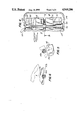
- FIG. 1 is a side sectional view of a preferred embodiment of the apparatus in accordance with the present invention.
- FIG. 2 is a bottom elevational view taken along the line 2--2 of FIG. 1;
- FIG. 3 is a top elevational view taken along line 3--3 of FIG. 1;
- FIG. 4 is a side sectional view taken along line 4--4 of FIG. 3;
- FIG. 5 is a bottom elevational view taken along line 5--5 of FIG. 4;
- FIG. 6 is a bottom elevational view taken along line 6--6 of FIG. 1;
- FIG. 7 is a graph representing the deceleration to which the read/write heads are subject v. time when an actuator impacts upon a prior art metal crash stop;
- FIG. 8 is a graph representing the deceleration to which the read/write heads are subjected v. time when the actuator impacts upon the crash stop of the present invention
- FIG. 9 is a schematic plot of deceleration v. deflection when an actuator impacts on a non-preloaded crash stop having an elastomeric bumper.
- FIG. 10 is a schematic plot of deceleration v. deflection when the actuator impacts on the crash stop of the present invention.
- the disk drive system 10 in accordance with the present invention includes a head actuator 12 upon which the read/write heads (not illustrated) are mounted, an actuator housing 14 and a shaft assembly 16 including a shaft 18.
- Shaft assembly 16 is mounted on actuator housing 14 by conventional means (not illustrated).
- Head actuator 12 is mounted in turn on shaft assembly 16 so as to be pivotally mounted to actuator housing 14 and thereby be capable of moving the read/write heads in bi-directional, arcuate paths across the disks.
- a coil 20 is mechanically coupled to actuator 12 at rearward end 21 of the actuator on a support bracket 22. It will be appreciated that the coil moves with the rotary movement of actuator 12.
- magnets 24 and 26 are fixedly mounted with respect to the actuator 12. By securing the magnets to the upper and lower magnetic plates 28 and 30 respectively, it is appreciated that magnets 24 and 26 are fixed as actuator 12, rotates about shaft 18.
- the upper and lower magnetic plates 28 and 30 are more specifically shown in FIGS. 2-4.
- the upper magnetic plate 28 includes two cavities 32a and 32b (FIG. 3), while lower magnetic plate 30 includes cavities 34a and 34b (FIG. 2).
- cavities 32a, 32b, 34a and 34b may be located in other fixed upper and lower plates.
- cavity 32b of upper magnetic plate 28 is substantially aligned with, but slightly displaced off-axis from, cavity 34b of lower magnetic plate 30. The displacement of cavity 32b is in the direction away from actuator travel; i.e. it is farther from the inner diameter of the hard disk than cavity 34b is.
- cavity 32a of upper magnetic plate 28 is substantially aligned with, but slightly displaced off-axis from, cavity 34b of lower magnetic plate 30.
- the displacement of cavity 32a is also in a direction away from actuator travel, which here is opposite the direction of displacement of cavity 32b, so that cavity 32a is further from the outer diameter of the hard disk than cavity 34a is.
- At least two crash stops 36 and 38 are provided.
- Inner diameter crash stop 36 limits pivoting movement of the actuator at the inner diameter of the hard disk.
- Outer diameter crash stop 38 limits movement of the actuator at the outer disk diameter.
- crash stops 36 and 38 are preloaded. This is accomplished by each crash stop being insertably retained within the corresponding cavities of the magnetic plates.
- inner diameter crash stop 36 is insertably received and retained within cavity 32a of upper magnetic plate and 34a of lower magnetic plate.
- outer diameter crash stop 38 is insertably received and retained within cavity 32b of upper magnetic plate and 34b of lower magnetic plate.
- each crash stop bends or curves in the direction of actuator 12 travel to preload each of the crash stops.
- the angle of the pin between upper and lower cavities thus functions to preload the pin.
- crash stops 36 and 38 are formed of a solid piece of spring material (e.g. steel); but this in and of itself produces a large rebound shock on the pivoting actuator 12 on initial contact with the crash stops, which shock could damage the head suspension mounted on the carriage.
- crash stops 36 and 38 each include a central generally cylindrical section 40a and 40b, respectively, formed of an elastomeric material such as rubber or urethane. This elastomeric bumper on the crash stop absorbs the large deceleration spike which is produced when the actuator mechanism impacts upon the solid piece of material of the crash stop.
- the free end 41 of inner diameter crash stop 36 is inserted through cavity 34b from the outside of disk drive 10 and is received within a cone-shaped section 42 of cavity 34a of the upper magnetic plate.
- Free end 43 of outer diameter crash stop 38 is inserted through cavity 34a from the outside of disk drive 10 and is received within cone-shaped section 44 of cavity 32b of the upper magnetic plate.
- the free ends 41, 43 slide along the inner surfaces of the respective cone-shaped sections 42, 44, which displace the free ends 41, 43 outwardly to cause the inward bowing of crash stops 36, 38 towards actuator 12 as described above and shown in FIG. 4.
- the present design provides for the clamping of the top of the crash stop within one of the magnetic plates.
- the inner diameter crash stop 36 includes a splined top 45 that expands as a plate fastener 46 is inserted therein from the outside of disk drive 10, thereby clamping the top section 37 of crash stop 36 within lower magnetic plate 30.
- the splined top of the outer diameter crash stop 38 is clamped to the upper magnetic plate 28 (not shown).
- the splined top of crash stop 38 is provided within cavity 32a and expands as another plate fastener is inserted therein thereby clamping the top section of the outer diameter crash stop 38 within the upper magnetic plate 28.
- other means besides the splined tops may be alternatively employed to lock the crash stops in position.
- the crash stop system of this invention provides for the reliable clamping of the crash stops within the structure of the magnetic plates.
- sections 40a and 40b are not exactly cylindrical in cross-section, but rather have eccentric cam surfaces. Ideally, the sections 40a, 40b should contact actuator 12 only a few cylinders (tracks) beyond the last data track.
- crash stops 36, 38 may be inserted through cavities 34a, 34b and into cavities 32a, 32b, but before they are locked in placed by, for example, the spline tops, crash stops 36, 38 may be rotated to position the respective cam surface at the desired point of contact.
- this structure permits the crash stops 36, 38 to be accessed for rotation from outside the disk drive system 10 by the insertion of a rotating tool, such as a screwdriver, into the splined tops.
- a rotating tool such as a screwdriver
- abutment members 48 and 50 are provided on each side of the support bracket 22 for coil 20.
- Abutment member 48 extends outwardly of support bracket 22 and is engageable with the central cylindrical portion 40a to reduce the rebound shock of the head actuator after it strikes the inner diameter crash stop 36.
- Abutment member 50 extends outwardly from support bracket 22 and is engageable toward the central cylindrical section 40b of the outer diameter crash stop 38 to reduce the rebound shock of the head actuator after it strikes the outer diameter crash stop.
- Each of the abutment members 48 and 50 includes a recessed opening 51a and 51b, respectively, which are capable of abutting against the crash stops 36 and 38, respectively.
- the abutment members 48 and 50 extend outwardly of the support bracket 22. Since the limit of movements of the head actuator between the inner track and outer track varies, the abutment member 48 has a larger recess 51a than recess 51b of abutment member 50.
- FIG. 7 represents the deceleration applied to the read/write heads during an emergency crash situation wherein a purely metal crash stop is employed.
- a large rebound shock is produced on the pivoting actuator carriage on initial contact with the crash stop which could damage the head suspension mounted on the carriage.
- this shock is absorbed (see FIG. 8) by utilizing the elastomeric material in the central cylindrical member of the crash stops.
- the crash stop of the present invention preloaded to provide a stopping force immediately upon impact with the carriage, but it is also capable of absorbing the large rebound shock associated with a crash stop being a solid piece of material.
- a non-preloaded crash stop with an elastomeric bumper is inefficient and disadvantageous in that a relatively large deflection of the crash stop is required before a significant deceleration force is applied.
- the energy required to stop the actuator which is equal to the kinetic energy of the actuator on impact, is proportional to the area under the curve up to the deflection at which the actuator is stopped. As may be seen, almost no deceleration is applied over small deflections.
- FIG. 10 illustrates in solid line that the crash stop in accordance with the present invention avoids this difficulty by providing significant deceleration even at small deflections.
- the area under the curve will be great enough without requiring the deflection to rise above a safe threshold.
- dashed line if the elastomeric section were not provided, significant deceleration would begin immediately on impact. The section is provided, however, to remove the spike shown in FIG. & and does not significantly increase the required deflection.
Abstract
Description
Claims (19)
Priority Applications (1)
| Application Number | Priority Date | Filing Date | Title |
|---|---|---|---|
| US07/226,280 US4949206A (en) | 1988-07-29 | 1988-07-29 | Crash stop for rotary disk drive actuator |
Applications Claiming Priority (1)
| Application Number | Priority Date | Filing Date | Title |
|---|---|---|---|
| US07/226,280 US4949206A (en) | 1988-07-29 | 1988-07-29 | Crash stop for rotary disk drive actuator |
Publications (1)
| Publication Number | Publication Date |
|---|---|
| US4949206A true US4949206A (en) | 1990-08-14 |
Family
ID=22848278
Family Applications (1)
| Application Number | Title | Priority Date | Filing Date |
|---|---|---|---|
| US07/226,280 Expired - Lifetime US4949206A (en) | 1988-07-29 | 1988-07-29 | Crash stop for rotary disk drive actuator |
Country Status (1)
| Country | Link |
|---|---|
| US (1) | US4949206A (en) |
Cited By (35)
| Publication number | Priority date | Publication date | Assignee | Title |
|---|---|---|---|---|
| US4841463A (en) * | 1986-08-07 | 1989-06-20 | Deutsche Itt Industries Gmbh | Nonrecursive digital filter |
| US5050026A (en) * | 1989-12-15 | 1991-09-17 | Magnetic Peripherals Inc. | Vertical flat coil for head actuator |
| US5109310A (en) * | 1989-03-07 | 1992-04-28 | Alps Electric Co., Ltd. | Disk drive device with unified actuator assembly |
| US5262913A (en) * | 1990-11-09 | 1993-11-16 | Seagate Technology, Inc. | Easily adjustable crash stop for a disc drive |
| US5369538A (en) * | 1992-11-12 | 1994-11-29 | Mitsumi Electric Co., Ltd. | Rotary disk drive actuator |
| US5402290A (en) * | 1993-06-14 | 1995-03-28 | Seagate Technology, Inc. | One piece limit stop for disc drive |
| US5414577A (en) * | 1993-04-23 | 1995-05-09 | Micropolis Corporation | Magnetically coupled hard disk drive head positioner latch |
| US5455726A (en) * | 1993-10-07 | 1995-10-03 | Micropolis Corporation | Versatile head positioner stop |
| US5581424A (en) * | 1992-09-21 | 1996-12-03 | Seagate Technology, Inc. | Magnetic crash stop and latch in a disc drive |
| US5715119A (en) * | 1996-06-07 | 1998-02-03 | Samsung Electronics, Inc. | Rotating crash stop assembly for hard disk drives |
| US5745325A (en) * | 1994-12-28 | 1998-04-28 | Fujitsu Limited | Magnetic disk drive having an improved outer stopper mechanism |
| US5864449A (en) * | 1997-08-22 | 1999-01-26 | International Business Machines Corporation | Precision limit stop for high density disk drives |
| US5905606A (en) * | 1997-07-29 | 1999-05-18 | International Business Machines Corporation | High-performance disk drive limit stop employing encapsulated visco-elastic material |
| US6021041A (en) * | 1997-06-09 | 2000-02-01 | Dell U.S.A., L.P | Tuned shock absorbing system for portable computer hard disc drives |
| US6125017A (en) * | 1998-03-20 | 2000-09-26 | Seagate Technology, Inc. | Actuator crash stops providing a two-stage braking impulse |
| US6172855B1 (en) | 1997-09-03 | 2001-01-09 | Samsung Electronics Co., Ltd. | Actuator latching device in hard disk drive |
| US6324034B1 (en) | 1999-06-24 | 2001-11-27 | Seagate Technology Llc | Spacer/stop assembly and disc drive with spacer/stop assembly |
| US6417986B1 (en) | 1998-11-16 | 2002-07-09 | Samsung Electronics Co., Ltd. | Impact guard for limiting hard disk movement |
| US6417994B1 (en) | 1999-04-22 | 2002-07-09 | Samsung Electronics, Co., Ltd. | Swage plate with protruded walls to increase retention torque in hard disk applications |
| US6446517B1 (en) | 2000-11-20 | 2002-09-10 | Samsung Electronics Company | Controlled particle deposition in drives and on media for thermal asperity studies |
| US6498703B2 (en) | 1999-05-12 | 2002-12-24 | Seagate Technology Llc | Inertial spring latch assembly in a disc drive |
| US6501614B1 (en) | 1999-08-19 | 2002-12-31 | Samsung Electronics Co., Ltd. | Acoustic insulator for controlling noise generated in a mass storage device |
| US6543124B2 (en) | 2001-01-18 | 2003-04-08 | Seagate Technology Llc | Voice coil motor attachment for a hard disc assembly |
| US6549372B1 (en) | 1998-12-15 | 2003-04-15 | Samsung Electronics Co., Ltd | Device for limiting head movement within a hard disk drive |
| US6590738B2 (en) | 2001-03-01 | 2003-07-08 | Samsung Electronics Co., Ltd. | Particle removal device in a hard disk drive |
| US6597144B2 (en) | 2000-06-21 | 2003-07-22 | Whirlpool Corporation | Method and apparatus for power loss detection and saving of operation settings in an appliance |
| US6680823B2 (en) | 2001-01-18 | 2004-01-20 | Seagate Technology Llc | Moveable outer stop |
| US6704161B1 (en) | 1998-11-06 | 2004-03-09 | Samsung Electronics Co. Ltd. | Shock protection skin bumper for a hard disk drive |
| US6744597B2 (en) | 1999-10-29 | 2004-06-01 | Samsung Electronics Co., Ltd. | Dynamic absorber for an actuator arm in a disk drive |
| US6744604B2 (en) | 2001-03-21 | 2004-06-01 | Seagate Technology Llc | Low particulating latch for a disc drive |
| US6762908B2 (en) | 2001-06-18 | 2004-07-13 | Samsung Electronics Co., Ltd. | Air razor and disk limiter for a hard disk drive |
| US6947252B2 (en) | 2000-05-10 | 2005-09-20 | Samsung Electronics Co., Ltd. | Wave stringer for controlling acoustic noise and shock vibration in a storage device |
| KR100630743B1 (en) | 2004-03-19 | 2006-10-02 | 삼성전자주식회사 | Yolk assembly with magnetic proximity latch and optional magnetic contact latch for contact start/stop hard disk drive, voice coil motor assembly having the same, and method of operating voice coil motor assembly |
| US8320086B1 (en) | 2010-06-28 | 2012-11-27 | Western Digital Technologies, Inc. | Disk drive crash stop including a helical portion |
| US8451564B2 (en) | 2010-12-27 | 2013-05-28 | HGST Netherlands B.V. | Impact energy dispersing crash stop for a hard disk drive |
Citations (9)
| Publication number | Priority date | Publication date | Assignee | Title |
|---|---|---|---|---|
| US4110802A (en) * | 1977-05-26 | 1978-08-29 | Memorex Corporation | Crash stop for disc drive actuator |
| US4237504A (en) * | 1979-01-26 | 1980-12-02 | Priam | Linear actuator including limit stop assembly for magnetic disc drive |
| US4346416A (en) * | 1980-02-29 | 1982-08-24 | Digital Equipment Corporation | Rotary actuator assembly for disk drive head positioner |
| US4439792A (en) * | 1981-05-22 | 1984-03-27 | U.S. Philips Corporation | Swing arm arrangement for a magnetic disc storage apparatus |
| US4471396A (en) * | 1981-05-14 | 1984-09-11 | Seagate Technology | Disc recording apparatus including integral track zero and crash stop means |
| US4603363A (en) * | 1983-03-01 | 1986-07-29 | Storage Technology Partners Ii | Stop mechanism using an elastomeric element |
| US4635151A (en) * | 1985-01-25 | 1987-01-06 | Priam Corporation | Rotary actuator having preloaded spring crash stop |
| US4716482A (en) * | 1986-02-14 | 1987-12-29 | Hewlett-Packard Company | Head actuator limit stop assembly for a disk memory drive |
| US4796131A (en) * | 1987-10-09 | 1989-01-03 | Micropolis Corporation | Head positioner preloaded stop |
-
1988
- 1988-07-29 US US07/226,280 patent/US4949206A/en not_active Expired - Lifetime
Patent Citations (9)
| Publication number | Priority date | Publication date | Assignee | Title |
|---|---|---|---|---|
| US4110802A (en) * | 1977-05-26 | 1978-08-29 | Memorex Corporation | Crash stop for disc drive actuator |
| US4237504A (en) * | 1979-01-26 | 1980-12-02 | Priam | Linear actuator including limit stop assembly for magnetic disc drive |
| US4346416A (en) * | 1980-02-29 | 1982-08-24 | Digital Equipment Corporation | Rotary actuator assembly for disk drive head positioner |
| US4471396A (en) * | 1981-05-14 | 1984-09-11 | Seagate Technology | Disc recording apparatus including integral track zero and crash stop means |
| US4439792A (en) * | 1981-05-22 | 1984-03-27 | U.S. Philips Corporation | Swing arm arrangement for a magnetic disc storage apparatus |
| US4603363A (en) * | 1983-03-01 | 1986-07-29 | Storage Technology Partners Ii | Stop mechanism using an elastomeric element |
| US4635151A (en) * | 1985-01-25 | 1987-01-06 | Priam Corporation | Rotary actuator having preloaded spring crash stop |
| US4716482A (en) * | 1986-02-14 | 1987-12-29 | Hewlett-Packard Company | Head actuator limit stop assembly for a disk memory drive |
| US4796131A (en) * | 1987-10-09 | 1989-01-03 | Micropolis Corporation | Head positioner preloaded stop |
Cited By (38)
| Publication number | Priority date | Publication date | Assignee | Title |
|---|---|---|---|---|
| US4841463A (en) * | 1986-08-07 | 1989-06-20 | Deutsche Itt Industries Gmbh | Nonrecursive digital filter |
| US5109310A (en) * | 1989-03-07 | 1992-04-28 | Alps Electric Co., Ltd. | Disk drive device with unified actuator assembly |
| US5050026A (en) * | 1989-12-15 | 1991-09-17 | Magnetic Peripherals Inc. | Vertical flat coil for head actuator |
| US5262913A (en) * | 1990-11-09 | 1993-11-16 | Seagate Technology, Inc. | Easily adjustable crash stop for a disc drive |
| US5581424A (en) * | 1992-09-21 | 1996-12-03 | Seagate Technology, Inc. | Magnetic crash stop and latch in a disc drive |
| US5369538A (en) * | 1992-11-12 | 1994-11-29 | Mitsumi Electric Co., Ltd. | Rotary disk drive actuator |
| US5414577A (en) * | 1993-04-23 | 1995-05-09 | Micropolis Corporation | Magnetically coupled hard disk drive head positioner latch |
| US5402290A (en) * | 1993-06-14 | 1995-03-28 | Seagate Technology, Inc. | One piece limit stop for disc drive |
| US5455726A (en) * | 1993-10-07 | 1995-10-03 | Micropolis Corporation | Versatile head positioner stop |
| US5745325A (en) * | 1994-12-28 | 1998-04-28 | Fujitsu Limited | Magnetic disk drive having an improved outer stopper mechanism |
| US6011672A (en) * | 1994-12-28 | 2000-01-04 | Fujitsu Limited | Magnetic disk drive having an improved outer stopper mechanism |
| US5715119A (en) * | 1996-06-07 | 1998-02-03 | Samsung Electronics, Inc. | Rotating crash stop assembly for hard disk drives |
| US6021041A (en) * | 1997-06-09 | 2000-02-01 | Dell U.S.A., L.P | Tuned shock absorbing system for portable computer hard disc drives |
| US5905606A (en) * | 1997-07-29 | 1999-05-18 | International Business Machines Corporation | High-performance disk drive limit stop employing encapsulated visco-elastic material |
| US5864449A (en) * | 1997-08-22 | 1999-01-26 | International Business Machines Corporation | Precision limit stop for high density disk drives |
| US6172855B1 (en) | 1997-09-03 | 2001-01-09 | Samsung Electronics Co., Ltd. | Actuator latching device in hard disk drive |
| US6125017A (en) * | 1998-03-20 | 2000-09-26 | Seagate Technology, Inc. | Actuator crash stops providing a two-stage braking impulse |
| US6704161B1 (en) | 1998-11-06 | 2004-03-09 | Samsung Electronics Co. Ltd. | Shock protection skin bumper for a hard disk drive |
| US6417986B1 (en) | 1998-11-16 | 2002-07-09 | Samsung Electronics Co., Ltd. | Impact guard for limiting hard disk movement |
| US6549372B1 (en) | 1998-12-15 | 2003-04-15 | Samsung Electronics Co., Ltd | Device for limiting head movement within a hard disk drive |
| US6417994B1 (en) | 1999-04-22 | 2002-07-09 | Samsung Electronics, Co., Ltd. | Swage plate with protruded walls to increase retention torque in hard disk applications |
| US6567242B2 (en) | 1999-05-12 | 2003-05-20 | Seagate Technology | Compressive limit stop in a disc drive |
| US6498703B2 (en) | 1999-05-12 | 2002-12-24 | Seagate Technology Llc | Inertial spring latch assembly in a disc drive |
| US6542335B1 (en) | 1999-05-12 | 2003-04-01 | Seagate Technology Llc | Inertial spring latch assembly and compressive limit stop in a disc drive |
| US6324034B1 (en) | 1999-06-24 | 2001-11-27 | Seagate Technology Llc | Spacer/stop assembly and disc drive with spacer/stop assembly |
| US6501614B1 (en) | 1999-08-19 | 2002-12-31 | Samsung Electronics Co., Ltd. | Acoustic insulator for controlling noise generated in a mass storage device |
| US6744597B2 (en) | 1999-10-29 | 2004-06-01 | Samsung Electronics Co., Ltd. | Dynamic absorber for an actuator arm in a disk drive |
| US6947252B2 (en) | 2000-05-10 | 2005-09-20 | Samsung Electronics Co., Ltd. | Wave stringer for controlling acoustic noise and shock vibration in a storage device |
| US6597144B2 (en) | 2000-06-21 | 2003-07-22 | Whirlpool Corporation | Method and apparatus for power loss detection and saving of operation settings in an appliance |
| US6446517B1 (en) | 2000-11-20 | 2002-09-10 | Samsung Electronics Company | Controlled particle deposition in drives and on media for thermal asperity studies |
| US6680823B2 (en) | 2001-01-18 | 2004-01-20 | Seagate Technology Llc | Moveable outer stop |
| US6543124B2 (en) | 2001-01-18 | 2003-04-08 | Seagate Technology Llc | Voice coil motor attachment for a hard disc assembly |
| US6590738B2 (en) | 2001-03-01 | 2003-07-08 | Samsung Electronics Co., Ltd. | Particle removal device in a hard disk drive |
| US6744604B2 (en) | 2001-03-21 | 2004-06-01 | Seagate Technology Llc | Low particulating latch for a disc drive |
| US6762908B2 (en) | 2001-06-18 | 2004-07-13 | Samsung Electronics Co., Ltd. | Air razor and disk limiter for a hard disk drive |
| KR100630743B1 (en) | 2004-03-19 | 2006-10-02 | 삼성전자주식회사 | Yolk assembly with magnetic proximity latch and optional magnetic contact latch for contact start/stop hard disk drive, voice coil motor assembly having the same, and method of operating voice coil motor assembly |
| US8320086B1 (en) | 2010-06-28 | 2012-11-27 | Western Digital Technologies, Inc. | Disk drive crash stop including a helical portion |
| US8451564B2 (en) | 2010-12-27 | 2013-05-28 | HGST Netherlands B.V. | Impact energy dispersing crash stop for a hard disk drive |
Similar Documents
| Publication | Publication Date | Title |
|---|---|---|
| US4949206A (en) | Crash stop for rotary disk drive actuator | |
| US5831795A (en) | Head loading mechanism for a disk drive | |
| US5365389A (en) | Crash stop and magnetic latch for optimum use of disc space | |
| US4110802A (en) | Crash stop for disc drive actuator | |
| EP1011096B1 (en) | Magnetic disk drive provided with load-unload mechanism | |
| US5003422A (en) | Magnetic head locking mechanism | |
| EP1956602A2 (en) | Actuator latch system of hard disk drive | |
| KR950027754A (en) | Data recording disc drives and magnetic recording disc drives | |
| US7564654B2 (en) | Actuator latch device for hard disk drive | |
| EP0597665B1 (en) | Disc drive latch | |
| CN1371514A (en) | Actuator shock snubber | |
| CA1285067C (en) | Carriage latch for a disc drive | |
| US5455726A (en) | Versatile head positioner stop | |
| US5012371A (en) | Disk drive crash stop/actuator latch | |
| US4117997A (en) | Motor isolation mount for disk drives | |
| US5477403A (en) | Disk drive having a crash stop detent actuator latch | |
| JPH01128273A (en) | Winchester disc srive memory device | |
| KR100809720B1 (en) | Actuator latch system for hard disk drive | |
| US20080055783A1 (en) | Actuator locking system of hard disk drive and method of locking actuator using the same | |
| JPS62287475A (en) | Disk device | |
| KR20030079686A (en) | A proximity latch mechanism using an impact rebound crash stop for an outside disk ramp loading disk drive | |
| US8125738B2 (en) | Actuator latch system of hard disk drive including latch lever having first and second hooks disposed one above the other at a leading end thereof | |
| DE19846166A1 (en) | Magnetic head for magneto-optic data storage system, e.g. minidisk | |
| CA2220304A1 (en) | Head loading mechanism for a disk drive | |
| JP2002100140A (en) | Inertia latching mechanism and actuator locking mechanism and magnetic disk unit using the same |
Legal Events
| Date | Code | Title | Description |
|---|---|---|---|
| AS | Assignment |
Owner name: STANDARD CHARTERED BANK, A BODY CORP. OF ENGLAND, Free format text: SECURITY INTEREST;ASSIGNOR:MINISCRIBE CORPORATION;REEL/FRAME:005203/0791 Effective date: 19890831 |
|
| AS | Assignment |
Owner name: MINISCRIBE CORPORATION, COLORADO Free format text: ASSIGNMENT OF ASSIGNORS INTEREST.;ASSIGNORS:PHILLIPS, WAYNE G.;NORMEN, DAVID F.;RUPP, RICHARD;REEL/FRAME:005359/0419 Effective date: 19880922 |
|
| STCF | Information on status: patent grant |
Free format text: PATENTED CASE |
|
| AS | Assignment |
Owner name: MAXTOR CORPORATION, 211 RIVER OAKS PARKWAY, SAN JO Free format text: ASSIGNMENT OF ASSIGNORS INTEREST.;ASSIGNOR:MINISCRIBE CORPORATION, A CORP. OF DELAWARE;REEL/FRAME:005573/0179 Effective date: 19910110 |
|
| FEPP | Fee payment procedure |
Free format text: PAYOR NUMBER ASSIGNED (ORIGINAL EVENT CODE: ASPN); ENTITY STATUS OF PATENT OWNER: LARGE ENTITY |
|
| AS | Assignment |
Owner name: BARCLAYS BANK PLC, AS AGENT Free format text: SECURITY INTEREST;ASSIGNOR:MAXTOR CORPORATION;REEL/FRAME:006627/0866 Effective date: 19930727 |
|
| AS | Assignment |
Owner name: CIT GROUP/BUSINESS CREDIT, INC., CALIFORNIA Free format text: ASSIGNMENT OF ASSIGNORS INTEREST;ASSIGNOR:MAXTOR CORPORATION;REEL/FRAME:006714/0408 Effective date: 19930916 Owner name: MAXTOR CORP., CALIFORNIA Free format text: ASSIGNMENT OF ASSIGNORS INTEREST;ASSIGNOR:BARCLAYS BANK PLC;REEL/FRAME:006826/0171 Effective date: 19930917 |
|
| FPAY | Fee payment |
Year of fee payment: 4 |
|
| FPAY | Fee payment |
Year of fee payment: 8 |
|
| FPAY | Fee payment |
Year of fee payment: 12 |
|
| AS | Assignment |
Owner name: JPMORGAN CHASE BANK, N.A., AS ADMINISTRATIVE AGENT Free format text: SECURITY AGREEMENT;ASSIGNORS:MAXTOR CORPORATION;SEAGATE TECHNOLOGY LLC;SEAGATE TECHNOLOGY INTERNATIONAL;REEL/FRAME:022757/0017 Effective date: 20090507 Owner name: WELLS FARGO BANK, NATIONAL ASSOCIATION, AS COLLATE Free format text: SECURITY AGREEMENT;ASSIGNORS:MAXTOR CORPORATION;SEAGATE TECHNOLOGY LLC;SEAGATE TECHNOLOGY INTERNATIONAL;REEL/FRAME:022757/0017 Effective date: 20090507 |
|
| AS | Assignment |
Owner name: MAXTOR CORPORATION, CALIFORNIA Free format text: RELEASE;ASSIGNOR:JPMORGAN CHASE BANK, N.A., AS ADMINISTRATIVE AGENT;REEL/FRAME:025662/0001 Effective date: 20110114 Owner name: SEAGATE TECHNOLOGY LLC, CALIFORNIA Free format text: RELEASE;ASSIGNOR:JPMORGAN CHASE BANK, N.A., AS ADMINISTRATIVE AGENT;REEL/FRAME:025662/0001 Effective date: 20110114 Owner name: SEAGATE TECHNOLOGY HDD HOLDINGS, CALIFORNIA Free format text: RELEASE;ASSIGNOR:JPMORGAN CHASE BANK, N.A., AS ADMINISTRATIVE AGENT;REEL/FRAME:025662/0001 Effective date: 20110114 Owner name: SEAGATE TECHNOLOGY INTERNATIONAL, CALIFORNIA Free format text: RELEASE;ASSIGNOR:JPMORGAN CHASE BANK, N.A., AS ADMINISTRATIVE AGENT;REEL/FRAME:025662/0001 Effective date: 20110114 |
|
| AS | Assignment |
Owner name: SEAGATE TECHNOLOGY LLC, CALIFORNIA Free format text: TERMINATION AND RELEASE OF SECURITY INTEREST IN PATENT RIGHTS;ASSIGNOR:WELLS FARGO BANK, NATIONAL ASSOCIATION, AS COLLATERAL AGENT AND SECOND PRIORITY REPRESENTATIVE;REEL/FRAME:030833/0001 Effective date: 20130312 Owner name: SEAGATE TECHNOLOGY US HOLDINGS, INC., CALIFORNIA Free format text: TERMINATION AND RELEASE OF SECURITY INTEREST IN PATENT RIGHTS;ASSIGNOR:WELLS FARGO BANK, NATIONAL ASSOCIATION, AS COLLATERAL AGENT AND SECOND PRIORITY REPRESENTATIVE;REEL/FRAME:030833/0001 Effective date: 20130312 Owner name: SEAGATE TECHNOLOGY INTERNATIONAL, CAYMAN ISLANDS Free format text: TERMINATION AND RELEASE OF SECURITY INTEREST IN PATENT RIGHTS;ASSIGNOR:WELLS FARGO BANK, NATIONAL ASSOCIATION, AS COLLATERAL AGENT AND SECOND PRIORITY REPRESENTATIVE;REEL/FRAME:030833/0001 Effective date: 20130312 Owner name: EVAULT INC. (F/K/A I365 INC.), CALIFORNIA Free format text: TERMINATION AND RELEASE OF SECURITY INTEREST IN PATENT RIGHTS;ASSIGNOR:WELLS FARGO BANK, NATIONAL ASSOCIATION, AS COLLATERAL AGENT AND SECOND PRIORITY REPRESENTATIVE;REEL/FRAME:030833/0001 Effective date: 20130312 |