US4919140A - Method and apparatus for regenerating nerves - Google Patents
Method and apparatus for regenerating nerves Download PDFInfo
- Publication number
- US4919140A US4919140A US07/258,142 US25814288A US4919140A US 4919140 A US4919140 A US 4919140A US 25814288 A US25814288 A US 25814288A US 4919140 A US4919140 A US 4919140A
- Authority
- US
- United States
- Prior art keywords
- nervous system
- central nervous
- electrical field
- axons
- spinal cord
- Prior art date
- Legal status (The legal status is an assumption and is not a legal conclusion. Google has not performed a legal analysis and makes no representation as to the accuracy of the status listed.)
- Expired - Lifetime
Links
Images

Classifications
-
- A—HUMAN NECESSITIES
- A61—MEDICAL OR VETERINARY SCIENCE; HYGIENE
- A61N—ELECTROTHERAPY; MAGNETOTHERAPY; RADIATION THERAPY; ULTRASOUND THERAPY
- A61N1/00—Electrotherapy; Circuits therefor
- A61N1/18—Applying electric currents by contact electrodes
- A61N1/32—Applying electric currents by contact electrodes alternating or intermittent currents
- A61N1/36—Applying electric currents by contact electrodes alternating or intermittent currents for stimulation
- A61N1/3605—Implantable neurostimulators for stimulating central or peripheral nerve system
- A61N1/3606—Implantable neurostimulators for stimulating central or peripheral nerve system adapted for a particular treatment
- A61N1/36103—Neuro-rehabilitation; Repair or reorganisation of neural tissue, e.g. after stroke
-
- A—HUMAN NECESSITIES
- A61—MEDICAL OR VETERINARY SCIENCE; HYGIENE
- A61N—ELECTROTHERAPY; MAGNETOTHERAPY; RADIATION THERAPY; ULTRASOUND THERAPY
- A61N1/00—Electrotherapy; Circuits therefor
- A61N1/02—Details
- A61N1/04—Electrodes
- A61N1/05—Electrodes for implantation or insertion into the body, e.g. heart electrode
- A61N1/0551—Spinal or peripheral nerve electrodes
- A61N1/0553—Paddle shaped electrodes, e.g. for laminotomy
-
- A—HUMAN NECESSITIES
- A61—MEDICAL OR VETERINARY SCIENCE; HYGIENE
- A61N—ELECTROTHERAPY; MAGNETOTHERAPY; RADIATION THERAPY; ULTRASOUND THERAPY
- A61N1/00—Electrotherapy; Circuits therefor
- A61N1/18—Applying electric currents by contact electrodes
- A61N1/32—Applying electric currents by contact electrodes alternating or intermittent currents
- A61N1/326—Applying electric currents by contact electrodes alternating or intermittent currents for promoting growth of cells, e.g. bone cells
Definitions
- This invention relates to a method and apparatus for causing nerves to regenerate, particularly, nerves in the central nervous system of mammals.
- Nerves in the peripheral nervous system of mammals are known to regenerate spontaneously. Further, past studies have shown that the regeneration of nerves in the peripheral nervous system of mammals can be stimulated by the application of electrical fields. Similar past studies have also shown that regeneration of nerves in the central nervous system of lower order vertebrates, such as lampreys, can be stimulated by the application of electrical fields.
- oscillating electrical field it is meant that a DC electrical field is imposed in one direction for a period of time to promote growth in one direction and the polarity of the field then reversed before die back of the oppositely facing axons begins or becomes significant.
- the nerves in the central nervous system of a mammal are stimulated to regenerate by applying an oscillating electrical field to the central nervous system.
- the oscillating electrical field is illustratively a constant current DC field the polarity of which is reversed after a predetermined time.
- the predetermined time is set to be less than the die-back period of anodal facing axons.
- FIG. 1 is a graph which shows the effect of an applied steady DC field over time on the growth of cathodal and anodal facing axons;
- FIG. 2 is a graph which shows the effect of an applied oscillating field over time on the growth of cathodal and anodal facing axons;
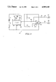
- FIG. 3 is a schematic of a circuit for generating an oscillation electrical field for stimulating nerve regeneration.
- nerves in the spinal cord of a mammal are stimulated to regenerate within the spinal cord by the application of an oscillating electrical field to the spinal cord.
- the oscillating electrical field is a constant current DC stimulus which is first applied in one direction for a predetermined period of time and then applied in the opposite direction for the predetermined period of time.
- the predetermined period of time which is the time period of one half-cycle of the oscillating electrical field, is selected to be less than the die back period of anodal facing axons but long enough to stimulate growth of cathodal facing axons. Applicants believe that in mammals, this predetermined period will need to be at least thirty seconds to stimulate growth of cathodal facing axons. This predetermined period will be termed the "polarity reversal period" of the oscillating electrical field.
- a lesion When the spinal cord of a mammal is injured, connections between nerves in the spinal cord are broken. Conventionally, the injured portion of the spinal cord is termed a lesion. Such lesions block the flow of nerve impulses for the nerve tracts affected by the lesion with resulting impairment to both sensory and motor function.
- the period of time which elapses from when a DC electrical field is first applied to when significant reabsorption or die back of the anodal facing axons begins will be termed the "die back period.” McCaig's experiments were conducted using embryonic spinal cord cells of frogs.
- FIGS. 1 and 2 show the affects on axon growth by an applied steady state DC electrical field (FIG. 1) and by an applied oscillating electrical field (FIG. 2).
- a nerve cell 10 is shown at the left-hand side of FIG. 1 having a cell body or soma 12 from which an axon 14 extends upwardly and an axon 16 extends downwardly.
- a constant current DC stimulus is applied to the nerve cell 10 such that axon 14 will be extending toward the cathode or negative pole of a DC stimulus signal and axon 16 will be extending toward the anode or positive pole of the DC stimulus.
- Axon 14 begins to grow almost immediately.
- Nerve cell 10 is shown at the left-hand side of FIG. 2 having a cell body 12, an upwardly extending axon 14 and a downwardly extending axon 16.
- a constant current DC stimulus is applied to nerve cell 10 such that axon 14 is extending toward the cathode ad axon 16 is extending toward the anode of the DC stimulus.
- the polarity of the DC stimulus is reversed. Axon 14 will now be extending toward the anode and axon 16 will be extending toward the cathode of the DC stimulus.
- the predetermined period of time is selected to be less than the die back period (D T ) of the anodal facing axon.
- D T die back period
- the predetermined period should not exceed one hour.
- this oscillating field stimulates growth of the axons facing both direction. This is due to the fact that growth of cathodal facing axons is stimulated almost immediately after the DC stimulus is applied but die back of the anodal facing axons does not become significant until after the die back period elapses.
- FIG. 3 is a schematic of a circuit for generating an oscillating field for application to the spinal cord of a mammal to stimulate nerve regeneration.
- Generator 20 includes a six volt battery 22, a power switch 23, a time 24, 6.2M resistor 26, 0.047 ⁇ F capacitor 28, 2M potentiometer 30, 1M resistors 32, 34, 36, 15K resistor 38, 1K resistor 40, and low power operational amplifier 42.
- timer 24 is a 14-stage ripple counter and oscillator chip such as a CD4060BE and low power operational amplifier 42 is an ICL7611 low power CMOS operational amplifier, both of which are manufactured by RCA.
- Battery 22 illustratively comprises two series connected three volt lithium dioxide battery cells such as DL2025 battery cells manufactured by Duracell.
- the positive terminal of battery 22 is coupled to the V+ terminal (pin 16) of the 14-stage ripple counter and oscillator chip which is timer 24 and to the V+ terminal (pin 7) of operational amplifier 42.
- Resistor 26, capacitor 28 and potentiometer 30 are used to set the frequency of the oscillator of the 14-stage ripple counter and oscillator chip.
- One terminal of resistor 26 is coupled to the clock input (pin 11) of timer 24 and its other terminal is coupled to a first terminal of capacitor 28 and to a first terminal of potentiometer 30.
- the first terminal of potentiometer 30 is also coupled to the wiper terminal of potentiometer 30.
- a second terminal of capacitor 26 is coupled to a first frequency set output (pin 9) of timer 24 and a second terminal of potentiometer 30 is coupled to a second frequency set output (pin 10) of timer 24.
- the V- terminal (pin 8) of timer 24 is coupled to a first terminal of switch 23.
- a second terminal of switch 23 is coupled to the negative terminal of battery 22.
- a reset input (pin 12) of timer 24 is also coupled to the first terminal of switch 23 as is the V- terminal (pin 4) of operational amplifier 42.
- An output (pin 3) of timer 24 is coupled through resistor 32 to the positive terminal of battery 22 and through resistor 38 to the negative input (pin 2) of operational amplifier 42.
- the positive input (pin 3) of operational amplifier 42 is coupled through resistor 34 to the positive terminal of battery 22 and through resistor 36 to the first terminal of switch 23.
- the negative input (pin 2) of operational amplifier 42 is coupled through resistor 40 to an output terminal 44.
- the output (pin 6) of operational amplifier 42 is coupled to an output terminal 46.
- Output terminal 44 of stimulator 20 is coupled to an electrode 48 and output terminal 46 is coupled to an electrode 50.
- electrodes 48, 50 comprise silastic insulated platinum electrodes.
- generator 20 When power switch 23 is closed, generator 20 generates an oscillating electrical field at output terminals 44, 46. That is, generator 20 generates a constant current DC stimulus the polarity of which is reversed periodically after the expiration of a predetermined period of time determined by timer 24.
- Output terminals 44, 46 will thus alternately comprise cathode and anode terminals, respectively, of generator 20 depending upon the polarity of the DC stimulus.
- the predetermined period of time determined by timer 24 is set by the frequency of the oscillator in the 14-stage ripple counter and oscillator chip which is timer 24.
- Potentiometer 30 is used to set the frequency of the oscillator in the 14-stage ripple counter and oscillator chip.
- the output of this oscillator can then be divided by up to 14 binary stages by the 14-stage ripple counter and oscillator chip to achieve very low frequency oscillations. If the frequency of this oscillator is illustratively set to 4.5 Hz and divided by these 14 binary stages, a frequency of one cycle per hour at the output (pin 3) of the 14-stage ripple counter and oscillator chip (timer 24) is produced which causes generator 20 to reverse polarity every thirty minutes.
- Applicants have found that a polarity reversal every fifteen minutes is effective to stimulate nerve regeneration in dogs, although a longer period would be more effective though possibly less safe. In guinea pig studies, applicants have used a polarity reversal period of thirty minutes to effectively stimulate nerve regeneration.
- the output of timer 24 is taken from the appropriate binary stage of the 14-stage ripple counter and oscillator chip, which, in the embodiment shown, is the output of the fourteenth stage (pin 3) and is a square wave oscillator between 0 VDC and 6 VDC (railed at the supply voltage) with a frequency determined as described above.
- This square wave is applied to the inverting input (pin 2) of operational amplifier 42.
- Resistors 34, 36 illustratively being equal, set up a 3 VDC reference voltage at the positive input (pin 3) of operational amplifier 42. Therefore, depending on whether the output of timer 24 is high or low, there will be a net +3 VDC or -3 VDC at the inverting input of operational amplifier 42 which drives current through electrodes 48, 50.
- the magnitude of the current sourced by generator 20 is determined by the value Rc in the equation: ##EQU1## where Rc is resistor 38 and the 3V is determined by the net voltage differential between the inverting and non-inverting inputs of operational amplifier 42.
- the quiescent current of operational amplifier 42 is set to 1 ⁇ A by strapping its pin 8 to +V. If generator 20 is to source more than 100 ⁇ A, the quiescent current of operational amplifier 42 is set to 10 ⁇ A by letting pin 8 float.
- the current sourced by generator 20 is selected to provide sufficient field strength in the section of the spinal cord in which nerve regeneration is to be stimulated. Applicants have found that a field strength of 200 ⁇ V/mm in the spinal cord will stimulate regeneration. The current needed to achieve this field strength is determined, such as by experiment, by the geometry of the animal in which generator 20 is used. Applicants have found that a current of 20 ⁇ A will provide a sufficient field strength to stimulate nerve regeneration in the spinal cords of guinea pigs whereas a current of about 200 ⁇ A is needed to provide sufficient field strength to stimulate nerve regeneration in the spinal cords of dogs weighing approximately twenty to thirty pounds.
- Power switch 23 is used to disconnect power to generator 20 until generator 20 is ready to be used. Timer 24 draws approximately 45 ⁇ A and to prevent this power drain from occuring prematurely, power switch 23 is used to keep power disconnected until generator 20 is put in use.
- generator 20 is packaged in a sealed package since it will preferrably be implanted in a subject.
- power switch 23 is illustratively a normally closed magnetic reed switch. A magnet is then detachably affixed to the packaged generator 20 to hold switch 23 open until generator 20 is ready for use. The magnet is then removed permitting the magnetic red switch which is power switch 23 to close.
- power switch 23 could be a latching magnetic reed switch.
- Power switch 23 could also be a sealed mechanical switch which can be actuated from outside the sealed package of generator 20.
- power switch 23 could be dispensed with altogether and either the positive or negative terminal of battery 22 left disconnected until generator 20 is ready for use. At that time, the terminal would be connected. This would, of course, require that the package in which generator 20 is placed be left open to some extent and sealed up at this time.
- Electrodes 48, 50 are implanted on opposite sides of a lesion in the spinal cord, respectively. Applicants have found that it is sufficient to implant electrodes 48, 50 in a laminectomy adjacent the spinal cord but not actually in the spinal cord. Further, in studies involving the application of a steady state DC electrical field, applicants have found that moving the anode from within the laminectomy to a site on the muscle dorsal to the same area results in only about a ten percent drop in field strength as does the converse of moving the cathode to a more superficial position while leaving the anode in the laminectomy. Further, uniform field homogenity can be achieved by locating the electrodes anywhere on the midline of the spinal cord, including locating both electrodes on the same side of the lesion but spaced apart, although locating the electrodes on opposite sides of the lesion is preferred.
- the field strength within the spinal cord at the site of the lesion depends upon the location of the current delivery electrodes.
- the convergence of current to an electrode produces high current density and hence higher field strength near each electrode.
- current direction becomes less uniform. At a lesion exactly half-way between two electrodes placed on the midline, the current will all be oriented along the long axis of the subject animal.
- the position of the other becomes relatively inconsequential and becomes a matter of convenience. It should be noted, however, that the electrodes can be located further from the lesion. If they are, the field strength of the electrical field at the lesion for a given magnitude of current will be reduced. Therefore, the magnitude of the current would have to be increased to yield the same electrical field strength at the lesion.
Abstract
Description
Claims (11)
Priority Applications (1)
| Application Number | Priority Date | Filing Date | Title |
|---|---|---|---|
| US07/258,142 US4919140A (en) | 1988-10-14 | 1988-10-14 | Method and apparatus for regenerating nerves |
Applications Claiming Priority (1)
| Application Number | Priority Date | Filing Date | Title |
|---|---|---|---|
| US07/258,142 US4919140A (en) | 1988-10-14 | 1988-10-14 | Method and apparatus for regenerating nerves |
Publications (1)
| Publication Number | Publication Date |
|---|---|
| US4919140A true US4919140A (en) | 1990-04-24 |
Family
ID=22979250
Family Applications (1)
| Application Number | Title | Priority Date | Filing Date |
|---|---|---|---|
| US07/258,142 Expired - Lifetime US4919140A (en) | 1988-10-14 | 1988-10-14 | Method and apparatus for regenerating nerves |
Country Status (1)
| Country | Link |
|---|---|
| US (1) | US4919140A (en) |
Cited By (56)
| Publication number | Priority date | Publication date | Assignee | Title |
|---|---|---|---|---|
| EP0486177A1 (en) * | 1990-10-26 | 1992-05-20 | Hamamatsu Photonics K.K. | Apparatus for current-assisted nerve cell connection |
| US5300096A (en) * | 1992-06-03 | 1994-04-05 | Hall H Eugene | Electromyographic treatment device |
| US5817142A (en) * | 1997-03-10 | 1998-10-06 | Corder; Lester J. | Electrical apparatus for killing micro-organisms in the human body |
| US5871506A (en) * | 1996-08-19 | 1999-02-16 | Mower; Morton M. | Augmentation of electrical conduction and contractility by biphasic cardiac pacing |
| US6095148A (en) * | 1995-11-03 | 2000-08-01 | Children's Medical Center Corporation | Neuronal stimulation using electrically conducting polymers |
| US6113886A (en) | 1996-02-06 | 2000-09-05 | Bruce Bryan | Bioluminescent novelty items |
| US6132360A (en) * | 1998-05-22 | 2000-10-17 | Halpern; Alan A. | Magnetic stretching of magnetized neurons for spinal cord or peripheral nerve repair and regeneration |
| US6136019A (en) * | 1996-08-19 | 2000-10-24 | Mower Family Chf Treatment Irrevocable Trust | Augmentation of electrical conduction and contractility by biphasic cardiac pacing administered via the cardiac blood pool |
| US6141587A (en) * | 1996-08-19 | 2000-10-31 | Mower Family Chf Treatment Irrevocable Trust | Augmentation of muscle contractility by biphasic stimulation |
| US6332096B1 (en) | 2000-02-16 | 2001-12-18 | Mower Chf Treatment Irrevocable Trust | Augmentation of electrical conduction and contractility by biphasic cardiac pacing |
| US6334069B1 (en) | 1998-01-15 | 2001-12-25 | Regenesis Biomedical, Inc. | Pulsed electromagnetic energy treatment apparatus and method |
| US6337995B1 (en) | 1996-08-19 | 2002-01-08 | Mower Chf Treatment Irrevocable Trust | Atrial sensing and multiple site stimulation as intervention for atrial fibrillation |
| US6341235B1 (en) | 1996-08-19 | 2002-01-22 | Mower Chf Treatment Irrevocable Trust | Augmentation of electrical conduction and contractility by biphasic cardiac pacing administered via the cardiac blood pool |
| US6343232B1 (en) | 1966-08-19 | 2002-01-29 | Mower Chf Treatment Irrevocable Trust | Augmentation of muscle contractility by biphasic stimulation |
| US6411847B1 (en) | 1996-08-19 | 2002-06-25 | Morton M. Mower | Apparatus for applying cyclic pacing at an average rate just above the intrinsic heart rate |
| US6411845B1 (en) | 1999-03-04 | 2002-06-25 | Mower Chf Treatment Irrevocable Trust | System for multiple site biphasic stimulation to revert ventricular arrhythmias |
| US20020095188A1 (en) * | 1996-08-19 | 2002-07-18 | Mower Morton M. | Antitachycardial pacing |
| US20020120309A1 (en) * | 2000-12-13 | 2002-08-29 | Richmond Frances J.R. | System and method for providing recovery from muscle denervation |
| US6458547B1 (en) | 1996-12-12 | 2002-10-01 | Prolume, Ltd. | Apparatus and method for detecting and identifying infectious agents |
| US6487450B1 (en) * | 2000-02-24 | 2002-11-26 | Cedars-Sinai Medical Center | System and method for preventing Sudden Cardiac Death by nerve sprouting from right stellate ganglion |
| WO2003000338A2 (en) * | 2001-06-21 | 2003-01-03 | Vanderbilt University | Method for promoting reinnervation of denervated tissue |
| WO2003041484A2 (en) * | 2001-11-13 | 2003-05-22 | Dynamed Systems, Llc | Apparatus and method for repair of spinal cord injury |
| US20030204197A1 (en) * | 2002-04-26 | 2003-10-30 | Medtronic, Inc. | Sintered titanium tube for the management of spinal cord injury |
| US20040127954A1 (en) * | 2002-09-04 | 2004-07-01 | The Washington University | Methods for treating central nervous system damage |
| US20040199043A1 (en) * | 2003-04-02 | 2004-10-07 | Donna Hancher | Severed spinal cord regeneration using natural processes and patient's own resources |
| US20040214790A1 (en) * | 2002-12-30 | 2004-10-28 | Purdue Research Foundation | Method of treatment for central nervous system injury |
| US20050059153A1 (en) * | 2003-01-22 | 2005-03-17 | George Frank R. | Electromagnetic activation of gene expression and cell growth |
| US20050069520A1 (en) * | 2001-04-24 | 2005-03-31 | Purdue Research Foundation | Methods and compositions for treating mammalian nerve tissue injuries |
| US20050277993A1 (en) * | 1996-08-19 | 2005-12-15 | Mower Morton M | System and method for managing detrimental cardiac remodeling |
| US20060167527A1 (en) * | 2001-11-13 | 2006-07-27 | Femano Philip A | Apparatus and method for repair of spinal cord injury |
| US20060194724A1 (en) * | 2005-02-25 | 2006-08-31 | Whitehurst Todd K | Methods and systems for nerve regeneration |
| WO2006133554A1 (en) * | 2005-06-15 | 2006-12-21 | Neurosilicon (1145990 Alberta Ltd.) | Electrically stimulating nerve regeneration |
| US20060292549A1 (en) * | 2005-06-15 | 2006-12-28 | Neurosilicon | Psychotropic drug screening device based on long-term photoconductive stimulation of neurons |
| US20070017530A1 (en) * | 2005-06-10 | 2007-01-25 | Syed Naweed I | Detecting electrical activity and assessing agents for the ability to influence electrical activity |
| US20070048731A1 (en) * | 2005-05-20 | 2007-03-01 | Neurosilicon | High throughput use-dependent assay based on stimulation of cells on a silicon surface |
| US7203537B2 (en) | 1996-08-19 | 2007-04-10 | Mr3 Medical, Llc | System and method for breaking reentry circuits by cooling cardiac tissue |
| US20070092958A1 (en) * | 2005-07-15 | 2007-04-26 | Syed Naweed I | Method and apparatus for guiding growth of neurons |
| US20070123945A1 (en) * | 2005-11-30 | 2007-05-31 | Cedars-Sinai Medical Center | Methods for the prediction of arrhythmias and prevention of sudden cardiac death |
| US7349739B2 (en) | 2002-05-03 | 2008-03-25 | Afferent Corporation | Method and apparatus for neurophysiologic performance |
| US20080077192A1 (en) * | 2002-05-03 | 2008-03-27 | Afferent Corporation | System and method for neuro-stimulation |
| EP1945299A2 (en) * | 2005-10-21 | 2008-07-23 | Purdue Research Foundation | Wireless electrical stimulation of neural injury |
| EP1945296A2 (en) * | 2005-10-21 | 2008-07-23 | Purdue Research Foundation | Telemetrically controllable system for treatment of nervous system injury |
| US20080287855A1 (en) * | 1996-08-19 | 2008-11-20 | Mower Morton M | System and method for managing detrimental cardiac remodeling |
| US20080306571A1 (en) * | 2005-03-16 | 2008-12-11 | Borgens Richard B | Devices For Treatment of Central Nervous System Injuries |
| US7582680B1 (en) | 1998-11-12 | 2009-09-01 | Purdue Research Foundation | Methods and compositions for treating mammalian spinal cord injuries |
| US20090318986A1 (en) * | 2008-06-20 | 2009-12-24 | Alo Kenneth M | Systems, Methods and Apparatus for Treating Cardiac Dysfunction with Neurostimulation |
| US20100094380A1 (en) * | 2008-10-15 | 2010-04-15 | Cochlear Limited | Electroneural interface for a medical implant |
| US7725178B2 (en) | 2004-06-30 | 2010-05-25 | Cedars-Sinai Medical Center | Method and system for the prediction of cardiac arrhythmias, myocardial ischemia, and other diseased condition of the heart associated with elevated sympathetic neural discharges |
| US7840264B1 (en) | 1996-08-19 | 2010-11-23 | Mr3 Medical, Llc | System and method for breaking reentry circuits by cooling cardiac tissue |
| US7908003B1 (en) | 1996-08-19 | 2011-03-15 | Mr3 Medical Llc | System and method for treating ischemia by improving cardiac efficiency |
| CN105030237A (en) * | 2015-07-17 | 2015-11-11 | 中国科学院电工研究所 | Spinal cord injury localization device |
| WO2016133960A1 (en) * | 2015-02-20 | 2016-08-25 | Research Foundation Of The City University Of New York | Methods and systems for treatment of spinal disorders using trans-spinal direct current stimulation |
| US10589089B2 (en) | 2017-10-25 | 2020-03-17 | Epineuron Technologies Inc. | Systems and methods for delivering neuroregenerative therapy |
| US11247043B2 (en) | 2019-10-01 | 2022-02-15 | Epineuron Technologies Inc. | Electrode interface devices for delivery of neuroregenerative therapy |
| US11247045B2 (en) | 2017-10-25 | 2022-02-15 | Epineuron Technologies Inc. | Systems and methods for delivering neuroregenerative therapy |
| US11865326B1 (en) | 1997-01-27 | 2024-01-09 | Innovations Holdings, L.L.C. | High precision, multi-output pulse and/or signal generators |
Citations (5)
| Publication number | Priority date | Publication date | Assignee | Title |
|---|---|---|---|---|
| US3817254A (en) * | 1972-05-08 | 1974-06-18 | Medtronic Inc | Transcutaneous stimulator and stimulation method |
| US3893462A (en) * | 1972-01-28 | 1975-07-08 | Esb Inc | Bioelectrochemical regenerator and stimulator devices and methods for applying electrical energy to cells and/or tissue in a living body |
| US4084595A (en) * | 1976-07-15 | 1978-04-18 | Med General, Inc. | Transcutaneous nerve stimulator |
| US4611599A (en) * | 1983-06-16 | 1986-09-16 | Richard Hugh Cameron Bentall | Electrical apparatus for influencing the metabolic characteristics of living systems |
| US4774967A (en) * | 1986-09-09 | 1988-10-04 | American Biointerface Corporation | Method and apparatus for mammalian nerve regeneration |
-
1988
- 1988-10-14 US US07/258,142 patent/US4919140A/en not_active Expired - Lifetime
Patent Citations (6)
| Publication number | Priority date | Publication date | Assignee | Title |
|---|---|---|---|---|
| US3893462A (en) * | 1972-01-28 | 1975-07-08 | Esb Inc | Bioelectrochemical regenerator and stimulator devices and methods for applying electrical energy to cells and/or tissue in a living body |
| US3893462B1 (en) * | 1972-01-28 | 1987-03-24 | ||
| US3817254A (en) * | 1972-05-08 | 1974-06-18 | Medtronic Inc | Transcutaneous stimulator and stimulation method |
| US4084595A (en) * | 1976-07-15 | 1978-04-18 | Med General, Inc. | Transcutaneous nerve stimulator |
| US4611599A (en) * | 1983-06-16 | 1986-09-16 | Richard Hugh Cameron Bentall | Electrical apparatus for influencing the metabolic characteristics of living systems |
| US4774967A (en) * | 1986-09-09 | 1988-10-04 | American Biointerface Corporation | Method and apparatus for mammalian nerve regeneration |
Non-Patent Citations (18)
| Title |
|---|
| "Final Thrusts Prepared in RES," Spinal Cord Society Newsletter, pp. 3-4, (Jun. 1987). |
| Berry, M., Regeneration in the Central Nervous System, Recent Advances in Neuropathology, Ch. 4, (1st ed. 1979), (Editors: W. T. Smith and V. B. Cavanaugh). * |
| Borgens, Richard B. A. Blight and M. McGinnis, "Behavioral Recovery Induced by Applied Electric Fields after Spinal Cord Hemisection in Guinea Pig," Science, 238:366-369, (Oct. 16, 1987). |
| Borgens, Richard B. A. Blight and M. McGinnis, Behavioral Recovery Induced by Applied Electric Fields after Spinal Cord Hemisection in Guinea Pig, Science, 238:366 369, (Oct. 16, 1987). * |
| Borgens, Richard B., A. Blight, D. Murphy & L. Stewart, "Transecte Dorsal Column Axons Within the Guinea Pig Spinal Cord Regenerate in the Presence of an Applied Electric Field," Journal of Comparative Neurology, 250:168-180, (1966). |
| Borgens, Richard B., A. Blight, D. Murphy & L. Stewart, Transecte Dorsal Column Axons Within the Guinea Pig Spinal Cord Regenerate in the Presence of an Applied Electric Field, Journal of Comparative Neurology, 250:168 180, (1966). * |
| Borgens, Richard E. and Michael E. McGinnis, Artificially Controlling Axonal Regeneration and Development by Applied Electric Fields, Chapter 4, Electric Fields in Vertebrate Repair, (1989). * |
| Final Thrusts Prepared in RES, Spinal Cord Society Newsletter, pp. 3 4, (Jun. 1987). * |
| Kiernan, J., "Hypotheses Concerned with Axonal Regeneration in the Mammalian Nervous System," Biol. Rev., 54:155-197, (1979). |
| Kiernan, J., Hypotheses Concerned with Axonal Regeneration in the Mammalian Nervous System, Biol. Rev., 54:155 197, (1979). * |
| M. F. Zanakis and M. J. Politis, Short Term Bahavioral and Histological Changes in the Damaged Rat Spinal Cord Following Application of D.C. Electric Fields, (Abstract). * |
| M. Khan, M. J. Politis and D. Munoz Garcia, The Effect of Localized Oriented Electric Fields on Regenerative Changes in Double Hemisectioned Spinal Cord of Rats, Canadian Congress of Neurological Sciences, Jun. 25 27, 1987, (Abstract). * |
| M. Khan, M. J. Politis and D. Munoz-Garcia, "The Effect of Localized Oriented Electric Fields on Regenerative Changes in Double Hemisectioned Spinal Cord of Rats," Canadian Congress of Neurological Sciences, Jun. 25-27, 1987, (Abstract). |
| McCaig, Colin D., "Spinal Neurite Reabsorption and Regrowth in vitro Depent on the Polarity of an Applied Electric Field,"Development, 100, 31-41, (1987). |
| McCaig, Colin D., Spinal Neurite Reabsorption and Regrowth in vitro Depent on the Polarity of an Applied Electric Field, Development, 100, 31 41, (1987). * |
| Politis, Michael J. and Michael F. Zanakis, "Short Term Efficacy of Applied Electric Fields in the Repair of the Damaged Rodent Spinal Cord: Behavioral and Morphological Results". |
| Politis, Michael J. and Michael F. Zanakis, Short Term Efficacy of Applied Electric Fields in the Repair of the Damaged Rodent Spinal Cord: Behavioral and Morphological Results . * |
| Wallace, M. Christopher, C. Tator and I. Piper, Recovery of Spinal Cord Function Induced by Direct Current Stimulation of the Injured Rat Spinal Cord, Neurosurgery, vol. 20, No. 6, Part I, (1987). * |
Cited By (109)
| Publication number | Priority date | Publication date | Assignee | Title |
|---|---|---|---|---|
| US6343232B1 (en) | 1966-08-19 | 2002-01-29 | Mower Chf Treatment Irrevocable Trust | Augmentation of muscle contractility by biphasic stimulation |
| US5224477A (en) * | 1990-10-26 | 1993-07-06 | Hamamatsu Photonics K.K. | Current-assisted nerve cell connection |
| EP0486177A1 (en) * | 1990-10-26 | 1992-05-20 | Hamamatsu Photonics K.K. | Apparatus for current-assisted nerve cell connection |
| US5300096A (en) * | 1992-06-03 | 1994-04-05 | Hall H Eugene | Electromyographic treatment device |
| US6095148A (en) * | 1995-11-03 | 2000-08-01 | Children's Medical Center Corporation | Neuronal stimulation using electrically conducting polymers |
| US6152358A (en) | 1996-02-06 | 2000-11-28 | Bruce Bryan | Bioluminescent novelty items |
| US6113886A (en) | 1996-02-06 | 2000-09-05 | Bruce Bryan | Bioluminescent novelty items |
| US6341235B1 (en) | 1996-08-19 | 2002-01-22 | Mower Chf Treatment Irrevocable Trust | Augmentation of electrical conduction and contractility by biphasic cardiac pacing administered via the cardiac blood pool |
| US6411847B1 (en) | 1996-08-19 | 2002-06-25 | Morton M. Mower | Apparatus for applying cyclic pacing at an average rate just above the intrinsic heart rate |
| US6141587A (en) * | 1996-08-19 | 2000-10-31 | Mower Family Chf Treatment Irrevocable Trust | Augmentation of muscle contractility by biphasic stimulation |
| US20080287855A1 (en) * | 1996-08-19 | 2008-11-20 | Mower Morton M | System and method for managing detrimental cardiac remodeling |
| US7203537B2 (en) | 1996-08-19 | 2007-04-10 | Mr3 Medical, Llc | System and method for breaking reentry circuits by cooling cardiac tissue |
| US5871506A (en) * | 1996-08-19 | 1999-02-16 | Mower; Morton M. | Augmentation of electrical conduction and contractility by biphasic cardiac pacing |
| US6337995B1 (en) | 1996-08-19 | 2002-01-08 | Mower Chf Treatment Irrevocable Trust | Atrial sensing and multiple site stimulation as intervention for atrial fibrillation |
| US6895274B2 (en) | 1996-08-19 | 2005-05-17 | The Mower Family Chf Treatment Irrevocable Trust | Antitachycardial pacing |
| US20050277993A1 (en) * | 1996-08-19 | 2005-12-15 | Mower Morton M | System and method for managing detrimental cardiac remodeling |
| US7440800B2 (en) | 1996-08-19 | 2008-10-21 | Mr3 Medical, Llc | System and method for managing detrimental cardiac remodeling |
| US7840264B1 (en) | 1996-08-19 | 2010-11-23 | Mr3 Medical, Llc | System and method for breaking reentry circuits by cooling cardiac tissue |
| US6136019A (en) * | 1996-08-19 | 2000-10-24 | Mower Family Chf Treatment Irrevocable Trust | Augmentation of electrical conduction and contractility by biphasic cardiac pacing administered via the cardiac blood pool |
| US7908003B1 (en) | 1996-08-19 | 2011-03-15 | Mr3 Medical Llc | System and method for treating ischemia by improving cardiac efficiency |
| US20020095188A1 (en) * | 1996-08-19 | 2002-07-18 | Mower Morton M. | Antitachycardial pacing |
| US20020099413A1 (en) * | 1996-08-19 | 2002-07-25 | Mower Morton M. | Augmentation of electrical conduction and contractility by biphasic cardiac pacing administered via the cardiac blood pool |
| US20060265017A9 (en) * | 1996-08-19 | 2006-11-23 | Mower Morton M | System and method for managing detrimental cardiac remodeling |
| US8447399B2 (en) | 1996-08-19 | 2013-05-21 | Mr3 Medical, Llc | System and method for managing detrimental cardiac remodeling |
| US8290585B2 (en) | 1996-08-19 | 2012-10-16 | Mr3 Medical, Llc | Augmentation of electrical conduction and contractility by biphasic cardiac pacing administered via the cardiac blood pool |
| US6458547B1 (en) | 1996-12-12 | 2002-10-01 | Prolume, Ltd. | Apparatus and method for detecting and identifying infectious agents |
| US6649357B2 (en) | 1996-12-12 | 2003-11-18 | Prolume, Ltd. | Apparatus and method for detecting and identifying infectious agents |
| US6649356B2 (en) | 1996-12-12 | 2003-11-18 | Prolume, Ltd. | Apparatus and method for detecting and identifying infectious agents |
| US11865326B1 (en) | 1997-01-27 | 2024-01-09 | Innovations Holdings, L.L.C. | High precision, multi-output pulse and/or signal generators |
| US5817142A (en) * | 1997-03-10 | 1998-10-06 | Corder; Lester J. | Electrical apparatus for killing micro-organisms in the human body |
| US6353763B1 (en) | 1998-01-15 | 2002-03-05 | Regenesis Biomedical, Inc. | Pulsed electromagnetic energy treatment apparatus and method |
| US20020040233A1 (en) * | 1998-01-15 | 2002-04-04 | George Frank R. | Pulsed electromagnetic energy treatment apparatus and method |
| US7024239B2 (en) | 1998-01-15 | 2006-04-04 | Regenesis Biomedical, Inc. | Pulsed electromagnetic energy treatment apparatus and method |
| US20060276845A1 (en) * | 1998-01-15 | 2006-12-07 | Regenesis Biomedical, Inc. | Pulsed electromagnetic energy treatment apparatus and method |
| US20110015698A1 (en) * | 1998-01-15 | 2011-01-20 | Regenesis Biomedical, Inc. | Pulsed electromagnetic energy treatment apparatus and method |
| US6334069B1 (en) | 1998-01-15 | 2001-12-25 | Regenesis Biomedical, Inc. | Pulsed electromagnetic energy treatment apparatus and method |
| US6132360A (en) * | 1998-05-22 | 2000-10-17 | Halpern; Alan A. | Magnetic stretching of magnetized neurons for spinal cord or peripheral nerve repair and regeneration |
| US8460646B2 (en) | 1998-11-12 | 2013-06-11 | Purdue Research Foundation | Methods and compositions for treating mammalian nerve tissue injuries |
| US9101655B2 (en) | 1998-11-12 | 2015-08-11 | Purdue Research Foundation | Methods and compositions for treating mammalian nerve tissue injuries |
| US20100016444A1 (en) * | 1998-11-12 | 2010-01-21 | Purdue Research Foundation | Methods and Compositions for Treating Mammalian Nerve Tissue Injuries |
| US7582680B1 (en) | 1998-11-12 | 2009-09-01 | Purdue Research Foundation | Methods and compositions for treating mammalian spinal cord injuries |
| US6411845B1 (en) | 1999-03-04 | 2002-06-25 | Mower Chf Treatment Irrevocable Trust | System for multiple site biphasic stimulation to revert ventricular arrhythmias |
| US6332096B1 (en) | 2000-02-16 | 2001-12-18 | Mower Chf Treatment Irrevocable Trust | Augmentation of electrical conduction and contractility by biphasic cardiac pacing |
| US6824538B2 (en) | 2000-02-24 | 2004-11-30 | Cedars-Sinai Medical Center | System for preventing sudden cardiac death by nerve sprouting from right stellate ganglion |
| US6487450B1 (en) * | 2000-02-24 | 2002-11-26 | Cedars-Sinai Medical Center | System and method for preventing Sudden Cardiac Death by nerve sprouting from right stellate ganglion |
| US6937904B2 (en) * | 2000-12-13 | 2005-08-30 | Alfred E. Mann Institute For Biomedical Engineering At The University Of Southern California | System and method for providing recovery from muscle denervation |
| US20020120309A1 (en) * | 2000-12-13 | 2002-08-29 | Richmond Frances J.R. | System and method for providing recovery from muscle denervation |
| US7837987B2 (en) | 2001-04-24 | 2010-11-23 | Purdue Research Foundation | Methods and compositions for treating mammalian nerve tissue injuries |
| US9687502B2 (en) | 2001-04-24 | 2017-06-27 | The University Of Chicago | Methods and compositions for treating mammalian nerve tissue injuries |
| US20050069520A1 (en) * | 2001-04-24 | 2005-03-31 | Purdue Research Foundation | Methods and compositions for treating mammalian nerve tissue injuries |
| US8065014B2 (en) * | 2001-06-21 | 2011-11-22 | Vanderbilt University | Method for promoting selective reinnervation of denervated tissue |
| WO2003000338A3 (en) * | 2001-06-21 | 2003-08-14 | Univ Vanderbilt | Method for promoting reinnervation of denervated tissue |
| US20040215290A1 (en) * | 2001-06-21 | 2004-10-28 | Zealear David L | Method for promoting reinnervation of denervated tissue |
| WO2003000338A2 (en) * | 2001-06-21 | 2003-01-03 | Vanderbilt University | Method for promoting reinnervation of denervated tissue |
| EP1453570A4 (en) * | 2001-11-13 | 2009-12-09 | Dynamed Systems Llc | Apparatus and method for repair of spinal cord injury |
| US20030105502A1 (en) * | 2001-11-13 | 2003-06-05 | Zanakis Michael J. | Apparatus and method for repair of spinal cord injury |
| US6975907B2 (en) | 2001-11-13 | 2005-12-13 | Dynamed Systems, Llc | Apparatus and method for repair of spinal cord injury |
| US20060167527A1 (en) * | 2001-11-13 | 2006-07-27 | Femano Philip A | Apparatus and method for repair of spinal cord injury |
| EP1453570A2 (en) * | 2001-11-13 | 2004-09-08 | Dynamed Systems, LLC | Apparatus and method for repair of spinal cord injury |
| AU2002343648B2 (en) * | 2001-11-13 | 2006-05-25 | Dynamed Systems, Llc | Apparatus and method for repair of spinal cord injury |
| WO2003041484A3 (en) * | 2001-11-13 | 2003-07-03 | Dynamed Systems Llc | Apparatus and method for repair of spinal cord injury |
| WO2003041484A2 (en) * | 2001-11-13 | 2003-05-22 | Dynamed Systems, Llc | Apparatus and method for repair of spinal cord injury |
| US7147647B2 (en) | 2002-04-26 | 2006-12-12 | Medtronic, Inc. | Sintered titanium tube for the management of spinal cord injury |
| US20030204197A1 (en) * | 2002-04-26 | 2003-10-30 | Medtronic, Inc. | Sintered titanium tube for the management of spinal cord injury |
| US9616234B2 (en) | 2002-05-03 | 2017-04-11 | Trustees Of Boston University | System and method for neuro-stimulation |
| US7349739B2 (en) | 2002-05-03 | 2008-03-25 | Afferent Corporation | Method and apparatus for neurophysiologic performance |
| US20080077192A1 (en) * | 2002-05-03 | 2008-03-27 | Afferent Corporation | System and method for neuro-stimulation |
| US20100114239A1 (en) * | 2002-09-04 | 2010-05-06 | Washington University | Methods for treating central nervous system damage |
| US7610096B2 (en) * | 2002-09-04 | 2009-10-27 | Washington University | Methods for treating central nervous system damage |
| US20040127954A1 (en) * | 2002-09-04 | 2004-07-01 | The Washington University | Methods for treating central nervous system damage |
| US7991477B2 (en) | 2002-09-04 | 2011-08-02 | Washington University | Methods for treating central nervous system damage |
| US20040214790A1 (en) * | 2002-12-30 | 2004-10-28 | Purdue Research Foundation | Method of treatment for central nervous system injury |
| EP1583544A2 (en) * | 2002-12-30 | 2005-10-12 | Purdue Research Foundation | Method of treatment for central nervous system injury |
| US20070219156A1 (en) * | 2002-12-30 | 2007-09-20 | Purdue Research Foundation Indiana University Research And Technology | Method of treatment for central nervous system injury |
| US7792576B2 (en) * | 2002-12-30 | 2010-09-07 | Purdue Research Foundation | Method of treatment for central nervous system injury |
| US7199110B2 (en) * | 2002-12-30 | 2007-04-03 | Purdue Research Foundation | Method of treatment for spinal cord injury |
| EP1583544A4 (en) * | 2002-12-30 | 2008-10-22 | Purdue Research Foundation | Method of treatment for central nervous system injury |
| US20050059153A1 (en) * | 2003-01-22 | 2005-03-17 | George Frank R. | Electromagnetic activation of gene expression and cell growth |
| US7121996B2 (en) | 2003-04-02 | 2006-10-17 | Donna Hancher | Severed spinal cord regeneration using natural processes and patient's own resources |
| US20040199043A1 (en) * | 2003-04-02 | 2004-10-07 | Donna Hancher | Severed spinal cord regeneration using natural processes and patient's own resources |
| US8744571B2 (en) | 2004-06-30 | 2014-06-03 | Cedars-Sinai Medical Center | Method and system for the prediction of cardiac arrhythmias, myocardial ischemia, and other diseased condition of the heart associated with elevated sympathetic neural discharges |
| US7725178B2 (en) | 2004-06-30 | 2010-05-25 | Cedars-Sinai Medical Center | Method and system for the prediction of cardiac arrhythmias, myocardial ischemia, and other diseased condition of the heart associated with elevated sympathetic neural discharges |
| US20060194724A1 (en) * | 2005-02-25 | 2006-08-31 | Whitehurst Todd K | Methods and systems for nerve regeneration |
| US20080306571A1 (en) * | 2005-03-16 | 2008-12-11 | Borgens Richard B | Devices For Treatment of Central Nervous System Injuries |
| US20070048731A1 (en) * | 2005-05-20 | 2007-03-01 | Neurosilicon | High throughput use-dependent assay based on stimulation of cells on a silicon surface |
| US20070017530A1 (en) * | 2005-06-10 | 2007-01-25 | Syed Naweed I | Detecting electrical activity and assessing agents for the ability to influence electrical activity |
| US20060287660A1 (en) * | 2005-06-15 | 2006-12-21 | Syed Naweed I | Electrically Stimulating Nerve Regeneration |
| US20060292549A1 (en) * | 2005-06-15 | 2006-12-28 | Neurosilicon | Psychotropic drug screening device based on long-term photoconductive stimulation of neurons |
| WO2006133554A1 (en) * | 2005-06-15 | 2006-12-21 | Neurosilicon (1145990 Alberta Ltd.) | Electrically stimulating nerve regeneration |
| US20070092958A1 (en) * | 2005-07-15 | 2007-04-26 | Syed Naweed I | Method and apparatus for guiding growth of neurons |
| EP1945296A4 (en) * | 2005-10-21 | 2010-01-20 | Purdue Research Foundation | Telemetrically controllable system for treatment of nervous system injury |
| EP1945296A2 (en) * | 2005-10-21 | 2008-07-23 | Purdue Research Foundation | Telemetrically controllable system for treatment of nervous system injury |
| US20090254148A1 (en) * | 2005-10-21 | 2009-10-08 | Borgens Richard B | Telemetrically Controllable System for Treatment of Nervous Sytem Injury |
| US20090132003A1 (en) * | 2005-10-21 | 2009-05-21 | Purdue Research Foundation | Wireless Electrical Stimulation of Neural Injury |
| EP1945299A4 (en) * | 2005-10-21 | 2009-04-15 | Purdue Research Foundation | Wireless electrical stimulation of neural injury |
| EP1945299A2 (en) * | 2005-10-21 | 2008-07-23 | Purdue Research Foundation | Wireless electrical stimulation of neural injury |
| US7822474B2 (en) | 2005-11-30 | 2010-10-26 | Cedars-Sinai Medical Center | Methods for the prediction of arrhythmias and prevention of sudden cardiac death |
| US20070123945A1 (en) * | 2005-11-30 | 2007-05-31 | Cedars-Sinai Medical Center | Methods for the prediction of arrhythmias and prevention of sudden cardiac death |
| US20090318986A1 (en) * | 2008-06-20 | 2009-12-24 | Alo Kenneth M | Systems, Methods and Apparatus for Treating Cardiac Dysfunction with Neurostimulation |
| US8447409B2 (en) * | 2008-10-15 | 2013-05-21 | Cochlear Limited | Electroneural interface for a medical implant |
| US20100094380A1 (en) * | 2008-10-15 | 2010-04-15 | Cochlear Limited | Electroneural interface for a medical implant |
| WO2016133960A1 (en) * | 2015-02-20 | 2016-08-25 | Research Foundation Of The City University Of New York | Methods and systems for treatment of spinal disorders using trans-spinal direct current stimulation |
| US10195424B2 (en) | 2015-02-20 | 2019-02-05 | The Research Foundation Of The City University Of New York | Methods and systems for treatment of spinal disorders using trans-spinal direct current stimulation |
| CN105030237A (en) * | 2015-07-17 | 2015-11-11 | 中国科学院电工研究所 | Spinal cord injury localization device |
| US10589089B2 (en) | 2017-10-25 | 2020-03-17 | Epineuron Technologies Inc. | Systems and methods for delivering neuroregenerative therapy |
| US11247045B2 (en) | 2017-10-25 | 2022-02-15 | Epineuron Technologies Inc. | Systems and methods for delivering neuroregenerative therapy |
| US11247044B2 (en) | 2017-10-25 | 2022-02-15 | Epineuron Technologies Inc. | Devices for delivering neuroregenerative therapy |
| US11247043B2 (en) | 2019-10-01 | 2022-02-15 | Epineuron Technologies Inc. | Electrode interface devices for delivery of neuroregenerative therapy |
| US11364381B2 (en) | 2019-10-01 | 2022-06-21 | Epineuron Technologies Inc. | Methods for delivering neuroregenerative therapy and reducing post-operative and chronic pain |
Similar Documents
| Publication | Publication Date | Title |
|---|---|---|
| US4919140A (en) | Method and apparatus for regenerating nerves | |
| EP1427474B1 (en) | Apparatus for bioelectric stimulation, healing acceleration and pain relief | |
| US4535775A (en) | Method for treatment of non-union bone fractures by non-invasive electrical stimulation | |
| Weiss et al. | Electrical stimulation and wound healing | |
| CA1069182A (en) | Muscle stimulator | |
| US20090132010A1 (en) | System and method for generating complex bioelectric stimulation signals while conserving power | |
| EP0977615B1 (en) | Apparatus for administering microcurrent electrotherapy | |
| US20090254148A1 (en) | Telemetrically Controllable System for Treatment of Nervous Sytem Injury | |
| US5413596A (en) | Digital electronic bone growth stimulator | |
| US20080306571A1 (en) | Devices For Treatment of Central Nervous System Injuries | |
| KR920703147A (en) | Method and apparatus for delivering ion penetrating medicine in pulse state | |
| EP0830875A3 (en) | Method for controlled stimulation of predetermined parts of the human body by application of variable electric signals | |
| NZ169605A (en) | Electromedical device: modifies electric potentials in non-human living bodies | |
| JPH05502608A (en) | Method and device for epilepsy treatment | |
| Valls-Sole et al. | Vibration-induced presynaptic inhibition of the soleus H reflex is temporarily reduced by cortical magnetic stimulation in human subjects | |
| US6792313B2 (en) | Muscle stimulation in a cast immobilized limo | |
| Pudenz | Neural stimulation: clinical and laboratory experiences | |
| Guan et al. | Circuit design considerations for power-efficient and safe implantable electrical neurostimulators | |
| EP0170668B1 (en) | An apparatus for treating scars | |
| US6757564B2 (en) | Medical system using biomolecular treatment | |
| CA1202683A (en) | Electronic acupuncture apparatus and method | |
| RU1813002C (en) | Apparatus for electrotherapeutic treatment | |
| CA1261401A (en) | Relieving headaches by application of specific electric pulses | |
| Wei et al. | A dedicated microprocessor for externally powered implantable pain controller | |
| AU2002329798A1 (en) | Apparatus and method for bioelectric stimulation, healing acceleration and pain relief |
Legal Events
| Date | Code | Title | Description |
|---|---|---|---|
| AS | Assignment |
Owner name: PURDUE RESEARCH FOUNDATION Free format text: ASSIGNMENT OF ASSIGNORS INTEREST.;ASSIGNORS:BORGENS, RICHARD B.;MCGINNIS, MICHAEL E.;REEL/FRAME:004992/0592 Effective date: 19881209 |
|
| STCF | Information on status: patent grant |
Free format text: PATENTED CASE |
|
| FEPP | Fee payment procedure |
Free format text: PAYOR NUMBER ASSIGNED (ORIGINAL EVENT CODE: ASPN); ENTITY STATUS OF PATENT OWNER: LARGE ENTITY |
|
| FPAY | Fee payment |
Year of fee payment: 4 |
|
| FEPP | Fee payment procedure |
Free format text: PAYER NUMBER DE-ASSIGNED (ORIGINAL EVENT CODE: RMPN); ENTITY STATUS OF PATENT OWNER: LARGE ENTITY Free format text: PAYOR NUMBER ASSIGNED (ORIGINAL EVENT CODE: ASPN); ENTITY STATUS OF PATENT OWNER: LARGE ENTITY |
|
| FPAY | Fee payment |
Year of fee payment: 8 |
|
| FPAY | Fee payment |
Year of fee payment: 12 |
|
| PTEF | Application for a patent term extension |
Free format text: PRODUCT NAME: ANDARA OFS SYSTEM; REQUESTED FOR 1 YEAR; HUMANITARIAN DEVICE EXEMPTION Filing date: 20080929 Expiry date: 20081014 |