US4545731A - Method and apparatus for producing a well - Google Patents
Method and apparatus for producing a well Download PDFInfo
- Publication number
- US4545731A US4545731A US06/576,854 US57685484A US4545731A US 4545731 A US4545731 A US 4545731A US 57685484 A US57685484 A US 57685484A US 4545731 A US4545731 A US 4545731A
- Authority
- US
- United States
- Prior art keywords
- power fluid
- gas
- chamber
- production
- tubing string
- Prior art date
- Legal status (The legal status is an assumption and is not a legal conclusion. Google has not performed a legal analysis and makes no representation as to the accuracy of the status listed.)
- Expired - Fee Related
Links
- 238000000034 method Methods 0.000 title abstract description 40
- 239000012530 fluid Substances 0.000 claims abstract description 296
- 238000004519 manufacturing process Methods 0.000 claims abstract description 181
- 230000015572 biosynthetic process Effects 0.000 claims abstract description 83
- 238000005086 pumping Methods 0.000 claims abstract description 13
- 238000006073 displacement reaction Methods 0.000 claims description 3
- 239000010779 crude oil Substances 0.000 abstract description 11
- 239000003921 oil Substances 0.000 abstract description 8
- 239000007789 gas Substances 0.000 description 148
- 210000002445 nipple Anatomy 0.000 description 8
- 230000000694 effects Effects 0.000 description 6
- 238000002347 injection Methods 0.000 description 6
- 239000007924 injection Substances 0.000 description 6
- 239000004215 Carbon black (E152) Substances 0.000 description 5
- 229930195733 hydrocarbon Natural products 0.000 description 5
- 150000002430 hydrocarbons Chemical class 0.000 description 5
- VNWKTOKETHGBQD-UHFFFAOYSA-N methane Chemical compound C VNWKTOKETHGBQD-UHFFFAOYSA-N 0.000 description 4
- 238000013022 venting Methods 0.000 description 4
- 239000002283 diesel fuel Substances 0.000 description 3
- 241001246312 Otis Species 0.000 description 2
- 230000007423 decrease Effects 0.000 description 2
- 239000000203 mixture Substances 0.000 description 2
- 239000003345 natural gas Substances 0.000 description 2
- 238000009825 accumulation Methods 0.000 description 1
- 238000005273 aeration Methods 0.000 description 1
- 238000010420 art technique Methods 0.000 description 1
- 239000002131 composite material Substances 0.000 description 1
- 238000011109 contamination Methods 0.000 description 1
- 230000009977 dual effect Effects 0.000 description 1
- 239000000295 fuel oil Substances 0.000 description 1
- 230000006872 improvement Effects 0.000 description 1
- 230000000977 initiatory effect Effects 0.000 description 1
- 239000007788 liquid Substances 0.000 description 1
- 230000008569 process Effects 0.000 description 1
- 230000003134 recirculating effect Effects 0.000 description 1
- 230000003252 repetitive effect Effects 0.000 description 1
- 230000004044 response Effects 0.000 description 1
- 230000000630 rising effect Effects 0.000 description 1
- 239000013049 sediment Substances 0.000 description 1
Images


Classifications
-
- F—MECHANICAL ENGINEERING; LIGHTING; HEATING; WEAPONS; BLASTING
- F04—POSITIVE - DISPLACEMENT MACHINES FOR LIQUIDS; PUMPS FOR LIQUIDS OR ELASTIC FLUIDS
- F04F—PUMPING OF FLUID BY DIRECT CONTACT OF ANOTHER FLUID OR BY USING INERTIA OF FLUID TO BE PUMPED; SIPHONS
- F04F1/00—Pumps using positively or negatively pressurised fluid medium acting directly on the liquid to be pumped
- F04F1/06—Pumps using positively or negatively pressurised fluid medium acting directly on the liquid to be pumped the fluid medium acting on the surface of the liquid to be pumped
- F04F1/08—Pumps using positively or negatively pressurised fluid medium acting directly on the liquid to be pumped the fluid medium acting on the surface of the liquid to be pumped specially adapted for raising liquids from great depths, e.g. in wells
-
- E—FIXED CONSTRUCTIONS
- E21—EARTH DRILLING; MINING
- E21B—EARTH DRILLING, e.g. DEEP DRILLING; OBTAINING OIL, GAS, WATER, SOLUBLE OR MELTABLE MATERIALS OR A SLURRY OF MINERALS FROM WELLS
- E21B43/00—Methods or apparatus for obtaining oil, gas, water, soluble or meltable materials or a slurry of minerals from wells
- E21B43/12—Methods or apparatus for controlling the flow of the obtained fluid to or in wells
- E21B43/121—Lifting well fluids
- E21B43/122—Gas lift
Definitions
- This invention relates to a method and apparatus for producing a well and more particularly relates to an improvement in a method and apparatus for producing hydrocarbon fluids from an earth formation through a well wherein the hydrocarbon fluids flow into a chamber in the well under formation pressure, are displaced from the chamber through a production tubing by a lower density power fluid, and the power fluid is thereafter removed from the chamber using steps including lift gas techniques to empty the chamber.
- Power fluid in the tubing is then gas lifted back to the surface face by introducing a gas under pressure into the well annulus above the upper packer and through gas lift valves spaced along the length of the power fluid tubing into the tubing where the lift gas mixes with the power fluid raising it back to the surface according to conventional gas lift procedure.
- the power fluid is removed, production fluid again flows from the earth formation into the production chamber for a repetition of the production cycle.
- the lowermost gas lift valve along the power fluid tubing is above the upper packer into which the lower end of the power fluid tubing connects.
- the lift gas injected into the power fluid tubing is effective for lifting the power fluid only along the tubing above the upper packer.
- the power fluid below the upper packer in the production chamber of the well can only be displaced from the chamber upwardly into the power fluid tubing by the formation pressure acting on the hydrocarbon fluids flowing upwardly into the production chamber for repeat of the cycle.
- the well casing is several times larger than the power fluid tubing and thus as the formation fluids flow into the production chamber, the power fluid displaced from the chamber upwardly in the power fluid tubing must be lifted several times the height of the rise of the formation fluid coming into the chamber thereby presenting substantial back pressure on the inflowing formation fluids.
- the power fluid such as diesel oil must be displaced by the formation fluid upwardly in the power fluid tubing 10.7 feet for each one foot rise in the formation fluid flowing into the production chamber.
- the power fluid such as diesel oil
- the inability of the lift gas to remove the power fluid from the power fluid tubing to a level no lower than the upper packer above the production chamber thus severely impairs the capabilities of the existing prior art method and system.
- a method and apparatus are provided for producing well fluids wherein well fluids flow under formation pressure into a defined production chamber in the well bore, are displaced from the production chamber through a producing tubing string by power fluid pumped into the production chamber, and the power fluid is removed to the surface using injected gas.
- the well system for carrying out the method includes a well extending to the producing formation, a lower packer set in the well above the producing formation, an upper packer set in the well spaced above the lower packer defining therebetween a production chamber, a production tubing string extending from the surface through the packers opening at the lower end below the lower packer, perforations in the production tubing string above the lower packer near the lower end of the production chamber, a first check valve in the production tubing string below the perforations, a second check valve in the production tubing string above the perforations, a power fluid tubing string from the surface to the upper packer opening at a lower end through the upper packer into the production chamber, a plurality of gas lift valves secured in spaced relation along the power fluid tubing string, the well wall around the production tubing string and power fluid tubing string above the upper packer defining a lift gas chamber, and means connected with the lowermost gas lift valve for directing lift gas into the production chamber to displace the power fluid from the chamber into the power fluid tub
- the method of the invention includes the steps of flowing production fluids from the well formation into the well bore below the lower packer and upwardly through the first check valve and production tubing string perforations into the production chamber under formation pressure until the production chamber is substantially filled, pumping power fluid through the power fluid tubing string into the production chamber displacing the production fluids from the production chamber through the perforations in the production tubing string and upwardly in the production tubing string through the second check valve until the production chamber is substantially filled with power fluid and the production fluids are substantially displaced from the production chamber, flowing lift gas into the lift gas chamber and through the gas lift valves into the power fluid tubing string until lift gas enters the production chamber through the lowermost gas lift valve the flow continuing until the lift gas has displaced substantially all of the power fluid from the production chamber and power fluid tubing string, stopping the flow of lift gas into the lift gas chamber, venting the power fluid tubing string to reduce the pressure in the production chamber to substantially atmospheric, and again flowing production fluids into the production chamber from below the lower packer until the production chamber is substantially refilled
- FIG. 1 is a schematic view in section and elevation showing well and surface apparatus comprising the system of the invention and illustrating the method of the invention at the initiation of the first step of displacing an essentially full production chamber by pumping power fluid into the chamber;
- FIG. 2 is a schematic view similar to FIG. 1 illustrating the completion of the first step of pumping the production fluid out of the production chamber with the power fluid;
- FIG. 3 is a schematic view similar to FIGS. 1 and 2 illustrating an intermediate stage in the step of removing the power fluid by injected lift gas;
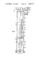
- FIG. 4 is a schematic view similar to FIGS. 1-3 illustrating an intermediate stage in the step of refilling the production chamber with production fluids after removal of the power fluid by the lift gas;
- FIG. 5 is an enlarged fragmentary view in section and elevation showing the lowermost gas lift valve and the connection of the upper end of the dip tube into the power fluid tubing string and lowermost gas lift valve;
- FIG. 6 is an enlarged fragmentary view in section of the vent valve connected into the power fluid tubing string showing the valve in open venting mode
- FIG. 7 is a fragmentary view in section of an alternate structure for introducing gas into the production chamber to remove power fluid.
- a well producing system 10 embodying the features of the invention includes a well bore 11 lined with a casing 12 perforated at 13 to admit well fluids to the well bore through the casing from a producing formation 14.
- the casing extends to a wellhead 15 at the surface end of the well bore.
- a lower single packer 20 is set in the casing above the perforations 13.
- An upper dual packer 21 is set in the casing spaced above the lower packer defining a production chamber 22 within the casing between the lower and upper packers.
- a string of production tubing 23 including a flow control valve 23a extends from the wellhead downwardly in the casing through the upper and lower packers.
- the lower end of the production tubing string opens below the lower packer for formation fluid flow from the well bore below the lower packer into the lower end of the production tubing string.
- a plurality of perforations 24 are provided in the production tubing string above the lower packer near the lower end of the production chamber 22.
- a first check valve 25 is mounted in the production tubing string between the lower end of the string and the perforations 24 to permit formation fluid flow upwardly into the production tubing string while preventing downward flow from the tubing string into the well below the lower packer.
- a second check valve 30 is installed in the production tubing string above the perforations 24 to permit upward flow in the production tubing string while precluding downward flow in the tubing string from above the second check valve.
- a power fluid tubing string 31 is connected through the wellhead downwardly in the well bore through the upper packer 21 opening at the lower end thereof into the upper end portion of the production chamber 22.
- a plurality of gas lift valves 32, 33, 34 and 35 are secured in spaced relation along the length of the power fluid tubing string 31.
- the inner wall of the casing 12 between the upper packer 21 and the wellhead 15 is a well annulus defining a gas lift chamber 40 for flow of lift gas in the casing to the gas lift valves 32-35.
- the lowermost gas lift valve 35 is secured into a nipple 41 mounted along the side of the power fluid tubing string 31 and has a flow passage 42 opening to a port 43 in the tubing string.
- the port 43 communicates with a flow passage 44 in an internal nipple 45 secured within the bore of the tubing string 31.
- a dip tube 50 is secured at an upper end into the nipple 45 and extends vertically downwardly in the production chamber 22.
- the bore of the dip tube opens at the upper end into the flow passage 44 of the nipple 45 and at the lower end 51 into the production chamber 22 spaced above the lower packer 20.
- the lower end 51 of the dip tube is preferably near the lower end of the production chamber 22 while being spaced sufficiently up the chamber from the lower packer 20 permit normal sediment accumulation in the lower end of the chamber without plugging the dip tube opening. It is necessary at all times during the operation of the system that the lower end of the dip tube be open for maximum lift gas flow into the chamber 22.
- the upper end portion of the dip tube as well as the nipple 45 supporting the dip tube are sufficiently smaller than the bore of the power fluid tubing 31 at the lower open end 52 of the power tubing to allow ample flow space for power fluid which is pumped into the chamber 22 and gas lifted out of the chamber through the open lower end of the power fluid tubing around the nipple 45 and upper end portion of the dip tube.
- a vent valve 53 is mounted on the power fluid tubing string 31 above the wellhead 15 to vent the bore of the tubing string to the atmosphere. Referring to FIG. 6, the vent valve 53 includes a tubular body 54 connected at a lower end into a nipple 55 welded on the power fluid tubing string 31 opening into the tubing string through a vent valve port 60.
- the vent valve has a stem 61 provided at the lower end with a valve 62 engageable with an internal annular seat 63 in the valve body to close the bore through the valve.
- the valve is shown in its normal open position.
- the valve is biased open by a coil spring 64 compressed within the bore of the body 54 between a flange 65 on the valve stem and the lower end of a cap 70 screwed into the upper end of the body.
- a stop shoulder 71 formed in the body limits the downward movement of the stop flange 65 on the valve stem.
- Side ports 72 in the valve body communicate with the bore 73 of the body around the valve stem and past the valve seat 63 and valve 62 into the tubing 31 through the port 60 for venting the power fluid tubing string to the atmosphere.
- a predetermined higher pressure within the tubing string 31 moves the valve 62 and stem 61 upwardly compressing the spring 64 closing the valve when the valve 62 engages the seat 63.
- the valve operates in response to the pressure changes in the power fluid tubing string closing during injection of power fluid and lift gas and opening when the flow of lift gas is terminated to vent the production chamber and power fluid tubing string.
- FIG. 1 Surface apparatus which may be used to operate the system and method of the invention for pumping the power fluid into the well bore and removing the power fluid with lift gas is illustrated in FIG. 1.
- a flow line 80 including a master valve 81 is connected at the wellhead 15 with the power fluid tubing string 31 to supply and remove power fluid.
- a power fluid supply line 82 and a return line 83 are connected with the line 80.
- the supply line 82 is connected with a pump 84 driven by a motor 85 which may be any one of a variety of prime movers such as a gas engine connected with a supply gas line 90 for gas provided through a regulator 91 and a control valve 92.
- the pump 84 has an intake line 93 leading to a power fluid reservoir 94.
- a motor valve 95 controlled by a valve operator 100 is connected in the power fluid supply line 82 for controlling flow of power fluid to the tubing string 31.
- the return line 83 also includes a motor valve 101 having a valve operator 102.
- the return line 83 connects into an oil and gas separator 104 which has an oil return line 105 leading to the reservoir 94 and a vent line 110 for venting separated gas to the atmosphere.
- the vent line 110 may if desired be connected with means, not shown, for returning the separated gas back into the lift gas supply for the well system.
- the separator 104 may be any available oil and gas separator which will process the returned mixture of power fluid and lift gas to separate the power fluid from the lift gas returning the power fluid to the reservoir 94 for reuse in a succeeding production cycle of the system.
- the separated lift gas may of course be either vented to the atmosphere or as previously stated returned to the lift gas supply for reuse.
- Lift gas for removing the power fluid from the system is supplied to the lift gas chamber 40 between the upper packer 21 and the wellhead 15 through a supply line 111 leading from a suitable supply source, not shown, of a gas which could be air or a natural gas at a suitable pressure.
- the lift gas system may include a compressor, not shown, as illustrated in U.S. Pat. No. 3,814,545.
- a motor valve 112 including an operator 113 is connected in the lift gas supply line 111 to control the supply outlift gas to the chamber 40.
- a gas operated motor valve controller 114 including a timing system is connected by line 115 with the lift gas supply line 111.
- the line 115 includes the valve 120 and a pressure regulator 121.
- the motor valve controller 114 may be an available gas operated controller such as an Otis Hi-Torc Automatic Controller as shown at pages 3556 and 3557 of the 1972-73 edition of the Composite Catalog of Oilfield Equipment and Services published by World Oil, Houston, Tex.
- the controller performs multiple timing and motor valve operator functions opening and closing the motor valves 100, 102, and 112.
- the controller is connected with the valves 100 and 102 by gas lines 122 and 123 respectively.
- the controller is connected with the valve 112 by a similar gas line, not shown.
- the controller is connected with the reservoir 94 by a line 124 so that the operation of the controller may respond to high and low levels of power fluid in the reservoir 94 if desired.
- the controller operates in a conventional manner opening and closing the controlled motor valves in accordance with a predetermined timing schedule programmed into the controller to provide the desired timing of the flow to and from the well of the power fluid, the lift gas, and the returning power fluid and lift gas mixture.
- FIG. 1 represents the method at the point in time when formation fluids such as heavy crude have flowed under formation pressure into the production chamber 22 between the packers 20 and 21 essentially filling the chamber.
- formation fluids such as heavy crude have flowed under formation pressure into the production chamber 22 between the packers 20 and 21 essentially filling the chamber.
- the formation fluids flow into the chamber 22 against essentially only atmospheric pressure in contrast with the fluid head pressure of a long column of power fluid in the prior art.
- the formation fluids from the formation 14 flowing under natural formation pressure pass through the perforations 13 of the casing 12 into the well bore 11 below the lower packer 20.
- the fluids then flow upwardly through the check valve 25 into the lower end portion of the production tubing string 23 and outwardly through the side ports 24 into the annular production chamber 22.
- Any production fluid from a previous production cycle in the tubing string 23 above the check valve 30 is supported in the tubing string by the check valve which is closed and thus the inflow of production fluid into the chamber 22 does not have to flow against the pressure of the column of production fluid in the tubing string 23.
- the formation fluids will flow into the chamber 22 so long as the formation pressure forcing the fluid into the chamber exceeds the back pressure of the column of fluid within the chamber.
- One of the criteria of course applied in designing the length of the chamber is the formation pressure available for displacing the fluid into the chamber.
- the chamber 22 would be designed with a length at least equal to the height to which the formation pressure would fill the chamber. In one particular example with a bottom hole pressure of 500 psi, the formation pressure would fill 1152 feet in the chamber 22 holding 37.8 barrels of fluid in a 7 inch casing.
- the step of displacing the formation fluid with power fluid begins.
- the power fluid is represented by reference numeral 132 shown in the chamber 22 above the innerface line 131 between the production fluid and the power fluid.
- the power fluid is a diesel oil of less density.
- the power fluid is pumped into the tubing string 31 through the open valves 95 and 81 in the line 82 by the pump 84 the intake of which pulls the power fluid from the reservoir 94.
- the power fluid flows downwardly in the tubing string 31 and outwardly through the lower open end 52 of the tubing string into the production chamber 22 above the body of the formation fluid 130.
- the power fluid flows into the chamber above the formation fluid and forcing the formation fluid downwardly into the production tubing string ports 24 and upwardly in the tubing string 23 through the check valve 30 to the wellhead at the surface.
- the pressure applied by the power fluid sufficiently exceeds the formation pressure to keep the check valve 25 closed.
- the power fluid is pumped into the chamber 22 until the chamber is essentially empty of formation fluid as represented in FIG. 2.
- the time during which the control valve 95 in the power fluid supply line 82 is open as determined by the timing setting of the controller 114 is set in accordance with the time required to pump a sufficient quantity of power fluid into the chamber to essentially empty the chamber.
- FIG. 2 shows a small quantity of formation fluid 130 remaining in the chamber 22 at the termination of pumping the power fluid and into the chamber. To avoid pumping power fluid up the production string 23 the amount of power fluid pumped in is desirably measured to leave the relatively small quantity represented in FIG. 2 in the lower end of the chamber at the completion of the step of pumping in the power fluid.
- the step of removing the power fluid with lift gas begins, an interim stage in such step being represented in FIG. 3.
- the controller 114 opens the valve 101 in the return line 83 leading to the separator 104 and the valve 112 in the lift gas supply line 111.
- Lift gas which may be natural gas or air flows into the lift gas chamber 40 between the upper packer 21 and the well head 15 through the supply line 111.
- the gas is admitted into the well annulus chamber 40 at a sufficient pressure calculated to displace the power fluid from the chamber 22 and the tubing string 31.
- the gas lift valves 32-35 inclusive are set at graduated opening pressures with the valve 32 having the highest opening pressure and the valve 35 the lowest.
- valves typically might be set with the following opening pressures: valve 32--800 psi; valve 33--775 psi; valve 34--750 psi; and valve 35--700 psi.
- opening pressures valve 32--800 psi; valve 33--775 psi; valve 34--750 psi; and valve 35--700 psi.
- lift gas injection into the tubing string 31 begins in the top gas lift valve 32 admitting the gas into the tubing string 31 where it mixes with the power fluid to lighten the column of fluid above the valve 32 and push the column upwardly in the tubing string 31 and outwardly through the line 80, valve 81, valve 101, and line 83 into the separator 104.
- the injection gas pressure in the chamber 40 decreases as the gas flows through the gas lift valve 32 to a level below 800 psi permitting the gas lift valve 32 to close.
- the normal design of a gas lift system positions the second gas lift valve 33 at a distance below the valve 32 which causes the valve 33 to begin to pass lift gas into the tubing string 31 before the closure of the gas lift valve 32 so that there is some overlap between the operation of the top gas lift valve and the second gas lift valve down the tubing string.
- the lift gas aerates the power fluid and with some piston effect pushes the column of power fluid above the second gas lift valve 33 upwardly through the tubing string 31 and outwardly into the separator 104 until the gas lift pressure decreases below 775 psi when the valve 33 closes.
- the valve 34 begins to pass lift gas shortly before the closure of the valve 33.
- the gas lift valves 34 and 35 may be spaced and designed to function simultaneously during the latter phases of removing the power fluid from the chamber 22 and tubing string 31.
- the bottom gas lift valve 35 is sized to dump the lift gas rapidly downwardly through the dip tube into the production chamber 22 at the same time that the gas lift valve 34 is continuing to admit lift gas into the tubing string 31.
- the valve 34 may be a continuous flow or aeration type valve to admit lift gas without producing a back pressure acting against the gas admitted to the production chamber through the bottom valve 35 which may be a large ported intermitting valve for a large volume rapid gas flow
- the rapid flow of lift gas through the dip tube and outwardly at the bottom end of the dip tube into the lower portion of the chamber 22 creates a piston-like or slug effect in the power fluid within the chamber 22 lifting the power fluid rather than aerating and lightening to force the power fluid upwardly into the lower end of the tubing string 31 around the upper end portion of the dip tube 50 and the nipple 45 into the tubing string.
- the column of power fluid being forced upwardly in the tubing 31 is aerated as the fluid passes the gas lift valve 34 which continues to admit lift gas while the gas lift valve 35 is dumping gas into the chamber 22 through the dip tube. Essentially all of the power fluid is displaced from the chamber 22 and gas lifted through the tubing string 31 into the separator 104. In the separator the liquid is separated from the gas and directed through the line 105 to the reservoir 94 for recirculating back to the production chamber in the next production cycle. The separated lift gas passes out through the vent 110 to the atmosphere or, alternatively, may be returned if desired to the source of lift gas through a vent line, not shown, from the separator.
- the amount of power fluid remaining in the chamber additionally is a function of how far the lower end 51 of the dip tube 50 is from the bottom of the chamber 22.
- the pressure of the formation fluids in the tubing string 23 is sufficient to prevent the gas in the chamber 22 from flowing into the production tubing string. Also the pressure of the gas in the chamber 22 is sufficient to keep formation fluids from flowing into the chamber through the check valve 25.
- the flow of lift gas through the line 111 is shut off by closing the valve 112.
- Closure of the valve 112 by the controller 114 may be set on a time basis calculated for the admission of a specific volume of lift gas for complete removal of the power fluid from the system.
- Another control of the valve 112 may respond to a high fluid level in the reservoir 94 indicating a return of a specific volume of power fluid from the well.
- FIG. 4 represents an intermediate stage in the step of refilling the chamber 22 with formation fluids which flow from the producing formation through the ports 13 into the well bore 11 and upwardly through the check valve 25 and the ports 24 into the chamber 22.
- FIG. 4 illustrates an interim stage in the refilling of the production chamber 22 with formation fluids.
- the formation fluids 130 are rising in the chamber and a layer of the residual power fluid 132 floats on the top surface of the formation fluids below the injection gas 133 which is at substantially atmospheric pressure and being displaced as the chamber refills with formation fluid.
- the line 134 represents the interface between the layer of power fluid 132 and the remaining lift gas 133.
- the formation fluids continue to flow into the chamber 22 until the chamber is essentially full as represented in FIG. 1 at which time the controller 114 reopens the valve 95 and starts the pump 84 to begin the next production cycle by pumping the power fluid into the chamber 22 through the tubing string 31 as previously described.
- the method of invention comprises the repetitive sequence of the steps of formation fluids flowing into the chamber 22, the power fluid being pumped into the chamber to produce the formation fluids from the chamber, and the removal of the power fluid from the chamber and the power fluid tubing string 31 using gas lift procedures.
- the gas lift procedures include both the steps of gas lifting the power fluid in the tubing string 31 as well as using the piston-like or slug effect to displace the power fluid from the chamber with lift gas introduced into the gas lift valve 35 and downwardly to the lower end portion of the chamber through the dip tube 50.
- an alternate well production system 10A embodying the features of the invention includes structure identical to that described and illustrated in FIG. 1 other than the apparatus for introducing gas into the production chamber 22 for removing the power fluid from the chamber through the well tubing string 31.
- the power fluid is displaced from the production chamber by introducing the lift gas into the upper end of the chamber rather than the lower end of the chamber and displacing the power fluid by a U-tube effect into the tubing string 31.
- a dip tube 140 is supported along an upper portion opening into the tubing string 31 at the upper end thereof and terminates and opens at a lower end near the lower end of the chamber 22.
- the dip tube 140 has a check valve 141 in the upper end portion of the tube permitting upward flow in the dip tube into the tubing string 31 while precluding downward flow through the dip tube.
- the upper end portion of the dip tube is mounted in concentric spaced relation within the lower end portion of the tubing string 31 to provide an annular discharge from the tubing string 31 around the dip tube into the upper end of the production chamber 22.
- One or more check valves 142 are secured between the upper end portion of the dip tube 140 and the tubing string 31 to permit downward flow of power fluid from the tubing string 31 into the upper end of the production chamber 22 and preclude upward flow from the production chamber into the tubing string 31 around the dip tube.
- the method of the invention carried out in the alternate production system 10A is identical to the method practiced in the system 10 with the exception of the steps employed to remove the power fluid from the production chamber 22 after the power fluid has displaced the production fluid into the tubing string 23.
- the power fluid is then pumped downwardly through the tubing string 31 through the check valve 142 at the lower end of the tubing string into the upper end of the production chamber 22 around the dip tube 140.
- the power fluid forces the formation production fluids into the tubing string 23 through the ports 24 as previously described.
- lift gas is then introduced into the tubing string 31 following the steps previously discussed.
- the bottom valve 35 permits lift gas to flow into the upper end of the production chamber 22 around the dip the 140 at a sufficiently rapid rate to effect a piston-like downward displacement of the power fluid in the production chamber 22 and upwardly through the open lower end of the dip tube 140 through the check valve 141 into the lower end of the tubing string 31 through which the power fluid returns to the surface assisted by aerating lift gas admitted through the valve 34.
- the check valve 142 prevents the lift gas from moving directly upwardly into the lower end of the tubing string 31 and thus confines the flow pattern of the lift gas to downward movement within the chamber 22 for the U-tube like displacement of the power fluid from the production chamber through the dip tube 140.
- the method steps continue as previously described repeating the cycle of again flowing formation production fluids into the production chamber and producing the fluids again by pumping in the power fluid.
- the method of practicing the invention in the system 10A differs from the method practiced in the system 10 only in the path followed by the lift gas in displacing the power fluid from the production chamber.
- the method and apparatus of the invention effectively and efficiently removes substantially more formation fluids during each production cycle than available in the prior art.
Abstract
Description
Claims (9)
Priority Applications (1)
| Application Number | Priority Date | Filing Date | Title |
|---|---|---|---|
| US06/576,854 US4545731A (en) | 1984-02-03 | 1984-02-03 | Method and apparatus for producing a well |
Applications Claiming Priority (1)
| Application Number | Priority Date | Filing Date | Title |
|---|---|---|---|
| US06/576,854 US4545731A (en) | 1984-02-03 | 1984-02-03 | Method and apparatus for producing a well |
Publications (1)
| Publication Number | Publication Date |
|---|---|
| US4545731A true US4545731A (en) | 1985-10-08 |
Family
ID=24306276
Family Applications (1)
| Application Number | Title | Priority Date | Filing Date |
|---|---|---|---|
| US06/576,854 Expired - Fee Related US4545731A (en) | 1984-02-03 | 1984-02-03 | Method and apparatus for producing a well |
Country Status (1)
| Country | Link |
|---|---|
| US (1) | US4545731A (en) |
Cited By (42)
| Publication number | Priority date | Publication date | Assignee | Title |
|---|---|---|---|---|
| US4708595A (en) * | 1984-08-10 | 1987-11-24 | Chevron Research Company | Intermittent oil well gas-lift apparatus |
| WO1988006209A1 (en) * | 1987-02-13 | 1988-08-25 | Holsteiner Gas Gmbh | Device for opening gas sources in refuse tips, and for exploring and cleansing materials for recycling and contaminated ground |
| FR2692003A1 (en) * | 1992-05-15 | 1993-12-10 | Lagoven Sa | Method and device for controlling the physical integrity of extraction tubes and extraction cladding in gas extraction wells. |
| US6092599A (en) * | 1997-08-22 | 2000-07-25 | Texaco Inc. | Downhole oil and water separation system and method |
| US6092600A (en) * | 1997-08-22 | 2000-07-25 | Texaco Inc. | Dual injection and lifting system using a rod driven progressive cavity pump and an electrical submersible pump and associate a method |
| US6105671A (en) * | 1997-09-23 | 2000-08-22 | Texaco Inc. | Method and apparatus for minimizing emulsion formation in a pumped oil well |
| US6123149A (en) * | 1997-09-23 | 2000-09-26 | Texaco Inc. | Dual injection and lifting system using an electrical submersible progressive cavity pump and an electrical submersible pump |
| US6131660A (en) * | 1997-09-23 | 2000-10-17 | Texaco Inc. | Dual injection and lifting system using rod pump and an electric submersible pump (ESP) |
| WO2001065062A2 (en) | 2000-03-02 | 2001-09-07 | Shell Internationale Research Maatschappij B.V. | Use of downhole high pressure gas in a gas-lift well |
| US6491105B2 (en) | 2001-02-14 | 2002-12-10 | Weatherford/Lamb, Inc. | Cross-over housing for gas lift valve |
| US20030048697A1 (en) * | 2000-03-02 | 2003-03-13 | Hirsch John Michele | Power generation using batteries with reconfigurable discharge |
| US20030066671A1 (en) * | 2000-03-02 | 2003-04-10 | Vinegar Harold J. | Oil well casing electrical power pick-off points |
| US6633164B2 (en) | 2000-01-24 | 2003-10-14 | Shell Oil Company | Measuring focused through-casing resistivity using induction chokes and also using well casing as the formation contact electrodes |
| US6633236B2 (en) | 2000-01-24 | 2003-10-14 | Shell Oil Company | Permanent downhole, wireless, two-way telemetry backbone using redundant repeaters |
| US6662875B2 (en) | 2000-01-24 | 2003-12-16 | Shell Oil Company | Induction choke for power distribution in piping structure |
| US6679332B2 (en) | 2000-01-24 | 2004-01-20 | Shell Oil Company | Petroleum well having downhole sensors, communication and power |
| US20040060703A1 (en) * | 2000-01-24 | 2004-04-01 | Stegemeier George Leo | Controlled downhole chemical injection |
| US6715550B2 (en) | 2000-01-24 | 2004-04-06 | Shell Oil Company | Controllable gas-lift well and valve |
| US6758277B2 (en) | 2000-01-24 | 2004-07-06 | Shell Oil Company | System and method for fluid flow optimization |
| US6817412B2 (en) | 2000-01-24 | 2004-11-16 | Shell Oil Company | Method and apparatus for the optimal predistortion of an electromagnetic signal in a downhole communication system |
| US6840317B2 (en) | 2000-03-02 | 2005-01-11 | Shell Oil Company | Wireless downwhole measurement and control for optimizing gas lift well and field performance |
| US6840316B2 (en) | 2000-01-24 | 2005-01-11 | Shell Oil Company | Tracker injection in a production well |
| US6851481B2 (en) | 2000-03-02 | 2005-02-08 | Shell Oil Company | Electro-hydraulically pressurized downhole valve actuator and method of use |
| US6868040B2 (en) | 2000-03-02 | 2005-03-15 | Shell Oil Company | Wireless power and communications cross-bar switch |
| US20060076140A1 (en) * | 2004-10-07 | 2006-04-13 | Schlumberger Technology Corporation | Gas Lift Apparatus and Method for Producing a Well |
| US20060113082A1 (en) * | 2004-11-29 | 2006-06-01 | Smith International, Inc. | Ported velocity tube for gas lift operations |
| US7073594B2 (en) | 2000-03-02 | 2006-07-11 | Shell Oil Company | Wireless downhole well interval inflow and injection control |
| US7114561B2 (en) | 2000-01-24 | 2006-10-03 | Shell Oil Company | Wireless communication using well casing |
| US7259688B2 (en) | 2000-01-24 | 2007-08-21 | Shell Oil Company | Wireless reservoir production control |
| US7322410B2 (en) | 2001-03-02 | 2008-01-29 | Shell Oil Company | Controllable production well packer |
| US20090038806A1 (en) * | 2007-08-10 | 2009-02-12 | Eog Resources, Inc. | Accumulation and recycling of captured gas in recovery of subterranean fluids |
| US20090194293A1 (en) * | 2008-02-04 | 2009-08-06 | Marathon Oil Company | Apparatus, assembly and process for injecting fluid into a subterranean well |
| EP2105578A1 (en) * | 2008-03-25 | 2009-09-30 | BJ Services Company | Dead string completion assembly with injection system and methods |
| US20090255684A1 (en) * | 2008-04-10 | 2009-10-15 | Bolding Jeffrey L | System and method for thru tubing deepening of gas lift |
| US20100101798A1 (en) * | 2008-10-23 | 2010-04-29 | Bp Corporation North America Inc. | Downhole systems and methods for deliquifaction of a wellbore |
| US20110042097A1 (en) * | 2008-02-04 | 2011-02-24 | Marathon Oil Company | Apparatus, assembly and process for injecting fluid into a subterranean well |
| US20110168413A1 (en) * | 2010-01-13 | 2011-07-14 | David Bachtell | System and Method for Optimizing Production in Gas-Lift Wells |
| US8631875B2 (en) | 2011-06-07 | 2014-01-21 | Baker Hughes Incorporated | Insert gas lift injection assembly for retrofitting string for alternative injection location |
| US20180038214A1 (en) * | 2016-08-04 | 2018-02-08 | Ge Oil & Gas Esp, Inc. | ESP Gas Slug Avoidance System |
| US10337296B2 (en) | 2014-10-14 | 2019-07-02 | Red Willow Production Company | Gas lift assembly |
| US11111764B2 (en) * | 2013-08-22 | 2021-09-07 | Schlumberger Technology Corporation | Wellbore annular safety valve and method |
| US20220298899A1 (en) * | 2020-08-06 | 2022-09-22 | Lift Plus Energy Solutions, Ltd. | Hybrid hydraulic gas pump system |
Citations (3)
| Publication number | Priority date | Publication date | Assignee | Title |
|---|---|---|---|---|
| US3324803A (en) * | 1965-04-27 | 1967-06-13 | Kelley Kork | Liquid control for gas wells |
| US3814545A (en) * | 1973-01-19 | 1974-06-04 | W Waters | Hydrogas lift system |
| US3963377A (en) * | 1974-05-20 | 1976-06-15 | Schlumberger Technology Corporation | Pneumatically powered pump system |
-
1984
- 1984-02-03 US US06/576,854 patent/US4545731A/en not_active Expired - Fee Related
Patent Citations (3)
| Publication number | Priority date | Publication date | Assignee | Title |
|---|---|---|---|---|
| US3324803A (en) * | 1965-04-27 | 1967-06-13 | Kelley Kork | Liquid control for gas wells |
| US3814545A (en) * | 1973-01-19 | 1974-06-04 | W Waters | Hydrogas lift system |
| US3963377A (en) * | 1974-05-20 | 1976-06-15 | Schlumberger Technology Corporation | Pneumatically powered pump system |
Non-Patent Citations (3)
| Title |
|---|
| Field Development Report OEC 5228, Otis Corporation, Dallas, TX, 1980. * |
| Otis Safety Systems & Automatic Control Equipment, pp. 3504 3505. * |
| Otis Safety Systems & Automatic Control Equipment, pp. 3504-3505. |
Cited By (59)
| Publication number | Priority date | Publication date | Assignee | Title |
|---|---|---|---|---|
| US4708595A (en) * | 1984-08-10 | 1987-11-24 | Chevron Research Company | Intermittent oil well gas-lift apparatus |
| WO1988006209A1 (en) * | 1987-02-13 | 1988-08-25 | Holsteiner Gas Gmbh | Device for opening gas sources in refuse tips, and for exploring and cleansing materials for recycling and contaminated ground |
| FR2692003A1 (en) * | 1992-05-15 | 1993-12-10 | Lagoven Sa | Method and device for controlling the physical integrity of extraction tubes and extraction cladding in gas extraction wells. |
| US6092599A (en) * | 1997-08-22 | 2000-07-25 | Texaco Inc. | Downhole oil and water separation system and method |
| US6092600A (en) * | 1997-08-22 | 2000-07-25 | Texaco Inc. | Dual injection and lifting system using a rod driven progressive cavity pump and an electrical submersible pump and associate a method |
| US6105671A (en) * | 1997-09-23 | 2000-08-22 | Texaco Inc. | Method and apparatus for minimizing emulsion formation in a pumped oil well |
| US6123149A (en) * | 1997-09-23 | 2000-09-26 | Texaco Inc. | Dual injection and lifting system using an electrical submersible progressive cavity pump and an electrical submersible pump |
| US6131660A (en) * | 1997-09-23 | 2000-10-17 | Texaco Inc. | Dual injection and lifting system using rod pump and an electric submersible pump (ESP) |
| US6633164B2 (en) | 2000-01-24 | 2003-10-14 | Shell Oil Company | Measuring focused through-casing resistivity using induction chokes and also using well casing as the formation contact electrodes |
| US7114561B2 (en) | 2000-01-24 | 2006-10-03 | Shell Oil Company | Wireless communication using well casing |
| US6840316B2 (en) | 2000-01-24 | 2005-01-11 | Shell Oil Company | Tracker injection in a production well |
| US6981553B2 (en) | 2000-01-24 | 2006-01-03 | Shell Oil Company | Controlled downhole chemical injection |
| US7259688B2 (en) | 2000-01-24 | 2007-08-21 | Shell Oil Company | Wireless reservoir production control |
| US6633236B2 (en) | 2000-01-24 | 2003-10-14 | Shell Oil Company | Permanent downhole, wireless, two-way telemetry backbone using redundant repeaters |
| US6662875B2 (en) | 2000-01-24 | 2003-12-16 | Shell Oil Company | Induction choke for power distribution in piping structure |
| US6679332B2 (en) | 2000-01-24 | 2004-01-20 | Shell Oil Company | Petroleum well having downhole sensors, communication and power |
| US20040060703A1 (en) * | 2000-01-24 | 2004-04-01 | Stegemeier George Leo | Controlled downhole chemical injection |
| US6715550B2 (en) | 2000-01-24 | 2004-04-06 | Shell Oil Company | Controllable gas-lift well and valve |
| US6758277B2 (en) | 2000-01-24 | 2004-07-06 | Shell Oil Company | System and method for fluid flow optimization |
| US6817412B2 (en) | 2000-01-24 | 2004-11-16 | Shell Oil Company | Method and apparatus for the optimal predistortion of an electromagnetic signal in a downhole communication system |
| US7075454B2 (en) | 2000-03-02 | 2006-07-11 | Shell Oil Company | Power generation using batteries with reconfigurable discharge |
| US7170424B2 (en) | 2000-03-02 | 2007-01-30 | Shell Oil Company | Oil well casting electrical power pick-off points |
| US6851481B2 (en) | 2000-03-02 | 2005-02-08 | Shell Oil Company | Electro-hydraulically pressurized downhole valve actuator and method of use |
| US6868040B2 (en) | 2000-03-02 | 2005-03-15 | Shell Oil Company | Wireless power and communications cross-bar switch |
| US20030066671A1 (en) * | 2000-03-02 | 2003-04-10 | Vinegar Harold J. | Oil well casing electrical power pick-off points |
| US6840317B2 (en) | 2000-03-02 | 2005-01-11 | Shell Oil Company | Wireless downwhole measurement and control for optimizing gas lift well and field performance |
| WO2001065062A2 (en) | 2000-03-02 | 2001-09-07 | Shell Internationale Research Maatschappij B.V. | Use of downhole high pressure gas in a gas-lift well |
| US20030048697A1 (en) * | 2000-03-02 | 2003-03-13 | Hirsch John Michele | Power generation using batteries with reconfigurable discharge |
| US7073594B2 (en) | 2000-03-02 | 2006-07-11 | Shell Oil Company | Wireless downhole well interval inflow and injection control |
| US7147059B2 (en) | 2000-03-02 | 2006-12-12 | Shell Oil Company | Use of downhole high pressure gas in a gas-lift well and associated methods |
| US6491105B2 (en) | 2001-02-14 | 2002-12-10 | Weatherford/Lamb, Inc. | Cross-over housing for gas lift valve |
| US7322410B2 (en) | 2001-03-02 | 2008-01-29 | Shell Oil Company | Controllable production well packer |
| US20060076140A1 (en) * | 2004-10-07 | 2006-04-13 | Schlumberger Technology Corporation | Gas Lift Apparatus and Method for Producing a Well |
| US20140209318A1 (en) * | 2004-10-07 | 2014-07-31 | Schlumberger Technology Corporation | Gas lift apparatus and method for producing a well |
| US8573310B2 (en) * | 2004-10-07 | 2013-11-05 | Schlumberger Technology Corporation | Gas lift apparatus and method for producing a well |
| US20060113082A1 (en) * | 2004-11-29 | 2006-06-01 | Smith International, Inc. | Ported velocity tube for gas lift operations |
| US7367401B2 (en) * | 2004-11-29 | 2008-05-06 | Smith International, Inc. | Ported velocity tube for gas lift operations |
| US20090038806A1 (en) * | 2007-08-10 | 2009-02-12 | Eog Resources, Inc. | Accumulation and recycling of captured gas in recovery of subterranean fluids |
| US8413726B2 (en) | 2008-02-04 | 2013-04-09 | Marathon Oil Company | Apparatus, assembly and process for injecting fluid into a subterranean well |
| US7766085B2 (en) | 2008-02-04 | 2010-08-03 | Marathon Oil Company | Apparatus, assembly and process for injecting fluid into a subterranean well |
| US20110042097A1 (en) * | 2008-02-04 | 2011-02-24 | Marathon Oil Company | Apparatus, assembly and process for injecting fluid into a subterranean well |
| US20090194293A1 (en) * | 2008-02-04 | 2009-08-06 | Marathon Oil Company | Apparatus, assembly and process for injecting fluid into a subterranean well |
| EP2105578A1 (en) * | 2008-03-25 | 2009-09-30 | BJ Services Company | Dead string completion assembly with injection system and methods |
| US8196663B2 (en) | 2008-03-25 | 2012-06-12 | Baker Hughes Incorporated | Dead string completion assembly with injection system and methods |
| US20090242208A1 (en) * | 2008-03-25 | 2009-10-01 | Bj Service Company | Dead string completion assembly with injection system and methods |
| US7954551B2 (en) * | 2008-04-10 | 2011-06-07 | Bj Services Company Llc | System and method for thru tubing deepening of gas lift |
| US20090255684A1 (en) * | 2008-04-10 | 2009-10-15 | Bolding Jeffrey L | System and method for thru tubing deepening of gas lift |
| US20100101798A1 (en) * | 2008-10-23 | 2010-04-29 | Bp Corporation North America Inc. | Downhole systems and methods for deliquifaction of a wellbore |
| US8302695B2 (en) | 2008-10-23 | 2012-11-06 | Bp Corporation North America Inc. | Downhole systems and methods for deliquifaction of a wellbore |
| US20110168413A1 (en) * | 2010-01-13 | 2011-07-14 | David Bachtell | System and Method for Optimizing Production in Gas-Lift Wells |
| US8113288B2 (en) | 2010-01-13 | 2012-02-14 | David Bachtell | System and method for optimizing production in gas-lift wells |
| US8631875B2 (en) | 2011-06-07 | 2014-01-21 | Baker Hughes Incorporated | Insert gas lift injection assembly for retrofitting string for alternative injection location |
| US11111764B2 (en) * | 2013-08-22 | 2021-09-07 | Schlumberger Technology Corporation | Wellbore annular safety valve and method |
| US10337296B2 (en) | 2014-10-14 | 2019-07-02 | Red Willow Production Company | Gas lift assembly |
| US20180038214A1 (en) * | 2016-08-04 | 2018-02-08 | Ge Oil & Gas Esp, Inc. | ESP Gas Slug Avoidance System |
| US11486243B2 (en) * | 2016-08-04 | 2022-11-01 | Baker Hughes Esp, Inc. | ESP gas slug avoidance system |
| US20230035369A1 (en) * | 2016-08-04 | 2023-02-02 | Baker Hughes Esp, Inc. | Esp gas slug avoidance system |
| US11802469B2 (en) * | 2016-08-04 | 2023-10-31 | Baker Hughes Esp, Inc. | ESP gas slug avoidance system |
| US20220298899A1 (en) * | 2020-08-06 | 2022-09-22 | Lift Plus Energy Solutions, Ltd. | Hybrid hydraulic gas pump system |
Similar Documents
| Publication | Publication Date | Title |
|---|---|---|
| US4545731A (en) | Method and apparatus for producing a well | |
| US6173768B1 (en) | Method and apparatus for downhole oil/water separation during oil well pumping operations | |
| AU749412B2 (en) | Gas displaced chamber lift system | |
| US6672392B2 (en) | Gas recovery apparatus, method and cycle having a three chamber evacuation phase for improved natural gas production and down-hole liquid management | |
| US3675714A (en) | Retrievable density control valve | |
| US4540348A (en) | Oilwell pump system and method | |
| US5211242A (en) | Apparatus and method for unloading production-inhibiting liquid from a well | |
| US5873410A (en) | Method and installation for pumping an oil-well effluent | |
| US20080135259A1 (en) | Reciprocated Pump System For Use In Oil Wells | |
| US4267888A (en) | Method and apparatus for positioning a treating liquid at the bottom of a well | |
| US7100695B2 (en) | Gas recovery apparatus, method and cycle having a three chamber evacuation phase and two liquid extraction phases for improved natural gas production | |
| US3617152A (en) | Well pumps | |
| US4662831A (en) | Apparatus for fracturing earth formations while pumping formation fluids | |
| GB2348225A (en) | Submersible pump assembly with a shunt valve. | |
| US5055002A (en) | Downhole pump with retrievable nozzle assembly | |
| US4025235A (en) | System for improving oil well production | |
| US4880062A (en) | Oil well downhole liquid injection assembly | |
| US4050854A (en) | Fluid lifting apparatus | |
| US3172469A (en) | U-tube well completion and method | |
| US4427345A (en) | Artificial lifting device and method | |
| US4465435A (en) | Apparatus for using natural gas pressure for pumping a well | |
| US9303503B2 (en) | Three-phase separation downhole | |
| US4237976A (en) | Hydraulic well pumping method | |
| US3986552A (en) | Pumping system for high viscosity oil | |
| US4565496A (en) | Oil well pump system and method |
Legal Events
| Date | Code | Title | Description |
|---|---|---|---|
| AS | Assignment |
Owner name: OTIS ENGINEERING CORPORATION,TEXAS Free format text: ASSIGNMENT OF ASSIGNORS INTEREST;ASSIGNORS:CANALIZO, CARLOS R.;HAYS, JAMES M.;SIGNING DATES FROM 19840531 TO 19840601;REEL/FRAME:004263/0840 Owner name: OTIS ENGINEERING CORPORATION CARROLLTON TEXAS A CO Free format text: ASSIGNMENT OF ASSIGNORS INTEREST.;ASSIGNORS:CANALIZO, CARLOS R.;HAYS, JAMES M.;REEL/FRAME:004263/0840;SIGNING DATES FROM 19840531 TO 19840601 |
|
| FEPP | Fee payment procedure |
Free format text: PAYOR NUMBER ASSIGNED (ORIGINAL EVENT CODE: ASPN); ENTITY STATUS OF PATENT OWNER: LARGE ENTITY |
|
| FPAY | Fee payment |
Year of fee payment: 4 |
|
| FPAY | Fee payment |
Year of fee payment: 8 |
|
| AS | Assignment |
Owner name: HALLIBURTON COMPANY, TEXAS Free format text: MERGER;ASSIGNOR:OTIS ENGINEERING CORPORATION;REEL/FRAME:006779/0356 Effective date: 19930624 |
|
| REMI | Maintenance fee reminder mailed | ||
| LAPS | Lapse for failure to pay maintenance fees | ||
| AS | Assignment |
Owner name: CAMCO INTERNATIONAL, INC., TEXAS Free format text: ASSIGNMENT OF ASSIGNORS INTEREST;ASSIGNOR:HALLIBURTON ENERGY SERIVCES, INC.;REEL/FRAME:009089/0174 Effective date: 19971009 |
|
| AS | Assignment |
Owner name: CAMCO INTERNATIONAL, INC., TEXAS Free format text: ASSIGNMENT OF ASSIGNORS INTEREST;ASSIGNOR:HALLIBURTON ENERGY SERVICES, INC.;REEL/FRAME:008753/0782 Effective date: 19971009 |
|
| FP | Lapsed due to failure to pay maintenance fee |
Effective date: 19971008 |
|
| STCH | Information on status: patent discontinuation |
Free format text: PATENT EXPIRED DUE TO NONPAYMENT OF MAINTENANCE FEES UNDER 37 CFR 1.362 |