US4496351A - Infusion monitor - Google Patents
Infusion monitor Download PDFInfo
- Publication number
- US4496351A US4496351A US06/502,585 US50258583A US4496351A US 4496351 A US4496351 A US 4496351A US 50258583 A US50258583 A US 50258583A US 4496351 A US4496351 A US 4496351A
- Authority
- US
- United States
- Prior art keywords
- cartridge
- monitor
- tube
- sensing
- dripper
- Prior art date
- Legal status (The legal status is an assumption and is not a legal conclusion. Google has not performed a legal analysis and makes no representation as to the accuracy of the status listed.)
- Expired - Fee Related
Links
Images


Classifications
-
- A—HUMAN NECESSITIES
- A61—MEDICAL OR VETERINARY SCIENCE; HYGIENE
- A61M—DEVICES FOR INTRODUCING MEDIA INTO, OR ONTO, THE BODY; DEVICES FOR TRANSDUCING BODY MEDIA OR FOR TAKING MEDIA FROM THE BODY; DEVICES FOR PRODUCING OR ENDING SLEEP OR STUPOR
- A61M5/00—Devices for bringing media into the body in a subcutaneous, intra-vascular or intramuscular way; Accessories therefor, e.g. filling or cleaning devices, arm-rests
- A61M5/14—Infusion devices, e.g. infusing by gravity; Blood infusion; Accessories therefor
- A61M5/168—Means for controlling media flow to the body or for metering media to the body, e.g. drip meters, counters ; Monitoring media flow to the body
- A61M5/16886—Means for controlling media flow to the body or for metering media to the body, e.g. drip meters, counters ; Monitoring media flow to the body for measuring fluid flow rate, i.e. flowmeters
- A61M5/1689—Drip counters
-
- A—HUMAN NECESSITIES
- A61—MEDICAL OR VETERINARY SCIENCE; HYGIENE
- A61M—DEVICES FOR INTRODUCING MEDIA INTO, OR ONTO, THE BODY; DEVICES FOR TRANSDUCING BODY MEDIA OR FOR TAKING MEDIA FROM THE BODY; DEVICES FOR PRODUCING OR ENDING SLEEP OR STUPOR
- A61M5/00—Devices for bringing media into the body in a subcutaneous, intra-vascular or intramuscular way; Accessories therefor, e.g. filling or cleaning devices, arm-rests
- A61M5/14—Infusion devices, e.g. infusing by gravity; Blood infusion; Accessories therefor
- A61M5/168—Means for controlling media flow to the body or for metering media to the body, e.g. drip meters, counters ; Monitoring media flow to the body
- A61M5/16804—Flow controllers
- A61M5/16813—Flow controllers by controlling the degree of opening of the flow line
-
- A—HUMAN NECESSITIES
- A61—MEDICAL OR VETERINARY SCIENCE; HYGIENE
- A61M—DEVICES FOR INTRODUCING MEDIA INTO, OR ONTO, THE BODY; DEVICES FOR TRANSDUCING BODY MEDIA OR FOR TAKING MEDIA FROM THE BODY; DEVICES FOR PRODUCING OR ENDING SLEEP OR STUPOR
- A61M39/00—Tubes, tube connectors, tube couplings, valves, access sites or the like, specially adapted for medical use
- A61M39/22—Valves or arrangement of valves
- A61M39/28—Clamping means for squeezing flexible tubes, e.g. roller clamps
- A61M39/281—Automatic tube cut-off devices, e.g. squeezing tube on detection of air
-
- Y—GENERAL TAGGING OF NEW TECHNOLOGICAL DEVELOPMENTS; GENERAL TAGGING OF CROSS-SECTIONAL TECHNOLOGIES SPANNING OVER SEVERAL SECTIONS OF THE IPC; TECHNICAL SUBJECTS COVERED BY FORMER USPC CROSS-REFERENCE ART COLLECTIONS [XRACs] AND DIGESTS
- Y10—TECHNICAL SUBJECTS COVERED BY FORMER USPC
- Y10S—TECHNICAL SUBJECTS COVERED BY FORMER USPC CROSS-REFERENCE ART COLLECTIONS [XRACs] AND DIGESTS
- Y10S128/00—Surgery
- Y10S128/13—Infusion monitoring
Definitions
- Intravenous liquid infusion means for infusing patients with food, blood, drugs, and the like are used in numerous medical applications.
- Infusion monitors usually comprise a suitable reservoir for the solution to be infused which is connected to a dripper and from which extends a feed tube leading to an intravenous needle for injection at the venipuncture point of the patient.
- a tube clamp is normally placed along the feed tube to control the flow of the liquid being infused.
- Proper infusion rates and volume may vary from a few cubic centimeters per hour to several cubic centimeters per minute. Hence, it is extremely important that the infusion rate and volume be accurately and continuously monitored and controlled.
- the optical sensing system is on both sides of the dripper tube, i.e. the emitter and the receiver are diagonally across from each other with the dripper tube therebetween. This necessitates positioning of the electrical or other controls on both sides of the tube which increases the size and weight of the monitor.
- the present invention avoids the above difficulties and has for one of its objects an improved infusion monitor which will automatically and continuously monitor and adjust the desired flow rate.
- Another object of the present invention is the provision of an improved infusion monitor which is light and simple so that it may be hung directly from the dripper tube.
- Another object of the present invention is the provision of an improved infusion monitor which will continuously indicate the amount of fluids infused into the patient.
- Another object of the present invention is the provision of an improved infusion monitor which may be pre-set to shut-off the flow when the desired volume has been administered.
- Another object of the present invention is the provision of an improved infusion monitor which is provided with warning devices which give signals at the patient's side and/or at the nurse's desk so that the attendant is alerted to any variation or stoppage of the pre-set infusion rate.
- Another object of the present invention is the provision of an improved monitor in which the optical sensing mechanism is on one side of the dripper tube.
- Another object of the present invention is the provision of an improved monitor in which the emitter and receiver of the optical sensing mechanism is on the same side of the dripper tube.
- Another object of the present invention is the provision of an improved monitor in which reflecting means are provided for said optical sensing mechanism to reflect the sensing beam for the emitter to the receiver.
- Another object of the present invention is the provision of an improved monitor in which the reflecting means are part of the clamping means.
- Another object of the present invention is the provision of an improved monitor in which means are provided for automatically aligning the dripper with the optical sensing means.
- Another object of the present invention is the provision of an improved monitor in which means are provided to virtually eliminate permanent crimping of the feeder tube.
- Another object of the present invention is the provision of an improved monitor which preferably uses a feeder tube squeezing mechanism which virtually eliminates permanent crimping of the feed tube.
- the instrument incorporates an electro-optical device which senses the drop rate and counts the number of drops infused. By pre-setting the unit to a predetermined number of drops per cubic centimeter, the number of drops counted by the optical system are translated to volume infused. This volume is continuously displayed on the instrument.
- a plastic feed tube leads from the dripper to the infusion needle and is attached to a squeezing mechanism operated by a motor in the instrument which automatically squeezes or releases the feed tube.
- the squeezer By pre-setting the desired drip rate, the squeezer will automatically squeeze or release the tube to tune the tube to allow the desired rate of drip only to be infused.
- the instrument may also be pre-set to the amount of liquid to be infused so that when the desired volume is reached, the instrument will command the squeezer to completely squeeze the tube and cut-off the flow.
- Fast and slow alarms alerted by both light and sound, may be provided and a continuous alarm may also be provided to constantly alert the attendant when the flow is continuous, the bag is empty, or there is an electrical failure. This same information may be transmitted to the attendant's desk or to any other alert system.
- the cartridge of the present invention is of such light weight that, together with the entire circuitry and the battery included therein, it may be hung from the dripper tube directly. Hence, the drops passing from the dripper tube may be sensed by the electro-optical sensing system of the present invention. This may be done without complicated clamping and sensing devices.
- the cartridge of the present invention provides an electro-optical sensing system in which the emitter and the receiver are on the same side of the cartridge and in which reflecting means are used to reflect the beam from the emitter back to the receiver.
- the reflecting means is part of the means for clamping the monitor cartridge on the dripper tube.
- the entire circuitry and electronics of the monitor is located on one side of the dripper tube so that the cartridge for the monitor can be made compact and light weight. Since the clamping mechanism is provided with the reflecting means and it is opposite the sensing means, the operator is assured that as soon as the cartridge is clamped onto the dripper tube, the electro-sensing and reflecting means are immediately in alignment with each other as well as in alignment with the dripper tube so that there is no danger of misalignment.
- the present invention preferably utilizes a tube-squeezing mechanism which minimizes, if not eliminates, any permanent crimping of the feeder tube so that when pressure on the feeder tube is released, the feeder tube returns substantially to its original configuration.
- FIG. 1 is a perspective view showing the fusion monitor of the present invention in use and feeding a patient.
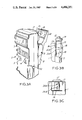
- FIG. 2 is a front view of the cartridge of the present invention.
- FIG. 3 is a rear view showing the unit in its operative position.
- FIG. 3A is a perspective view of the front portion of the cartridge.
- FIG. 3B is a detail partly in section showing the optical-sensing and reflecting mechanism of the present invention.
- FIG. 3C is a partial plan view of the openings for the optical-sensing mechanism of the present invention.
- FIG. 3D is a fragmentary perspective view of the tube-squeezing mechanism preferably used with the present invention.
- FIG. 3E is a sectional view taken along line 3E--3E of FIG. 3D showing the feeder tube being squeezed.
- FIG. 3F is a sectional view similar to FIG. 3E showing the feeder tube after pressure has been released therefrom.
- FIG. 3G is an enlarged sectional view of the edge of the preferred squeezing mechanism.
- FIG. 4 is a fragmentary plan view showing the automatic tube squeezer mechanism.
- FIG. 4A is a schematic elevational view showing an alternate means for raising and lowering the tube-squeezing mechanism.
- FIG. 5 is a diagrammatic block view showing the circuit used with the present invention.
- FIGS. 6A and 6B are diagrammatic views showing the circuit in greater detail.
- FIG. 7 is another diagrammatic view showing the circuit in still greater detail.
- the improved infusion monitor of the present invention comprises an outer cartridge 1 within which the circuitry and battery is packaged.
- the infusion liquid is usually stored in a transparent container 20 which may be a rigid or flexible container and may be made of a glass or plastic material.
- the container 20 is provided with a hanging opening 21 at the top from which it may hang on a hook 22 of an I. V. stand and has an outlet tube 23 at the bottom.
- Visual measuring indicia 24 may also be provided on the container 20 to give the attendant a visual indication of the amount of fluid remaining therein.
- a dripper assembly 15 is inserted in the outlet tube 23.
- the dripper 15 is provided with an upper flange 14 at its top and is adapted to have a hollow feed tube 27 attached to the bottom thereof.
- the dripper 15 is a hollow structure preferably made of a transparent plastic or glass material, as is usual in such products.
- the feeder tube 27 has an intravenous needle 28 attached thereto at its lower end which is adapted to be inserted into the patient for feeding the patient.
- Display devices 2 are provided in the cartridge 1 to indicate amounts infused as well as to indicate whether the battery is charged and whether the rate of infusion is slow, fast or in tune as will be described in greater detail hereinbelow.
- the cartridge is also provided with a plurality of switch assemblies 3, 4 and 5 which may be used to pre-set the desired volume, the desired rate and the desired drip-type. The number of drops per CC is pre-set as indicated on the dripper, so that the number of drops counted is translated into infused volume.
- a charger jack and nurse call instrument outlet 6 may also be provided.
- the rear of the cartridge 1 is provided with a clamping assembly in the form of a two-arm lever 9 which is pivotally mounted thereto at pivot 11.
- the clamping assembly 9 has a clamp 10 at the end of its upper arm and a mirror handle 12, which is used to open and close the clamp 10, at the end of its lower arm.
- a wire hinge 13 is provided which has an arcuate portion 17 which is adapted to rest on the upper dripper flange 14 of the dripper 15.
- the dripper tube 15 is adapted to lie in a concave seating surface 16 at the rear of the cartridge 1 and is held in place by the spring-pressed clamp 10. It will be seen from this structure that the cooperation between the wire hinge 13 and the clamp 10 together with the seating surface 16 permits the cartridge 1 to be quickly and easily mounted onto the dripper 15.
- the flange 14 of the dripper 15 extends above the top edge of the cartridge 1 and the hinge 13 hangs over and rests on the flange 14 so that when the clamp 10 applies pressure to the dripper 15, it will be held tightly within and against the seating surface 16 of the cartridge 1. Hence, the cartridge 1 may be very quickly and easily assembled onto the dripper 15 and may be just as easily disassembled therefrom.
- the concave holder 16 is provided with a pair of vertically oriented aligned optical sensing openings 26 which permit sensing beams from the sensing means to pass therethrough. These sensing beams sense the liquid drops as they pass down the dripper tube 15 and are thus able to count the number of drops and determine the rate of infusion.
- a flexible feed tube 27 leads from the dripper 15 and is adapted to be squeezed to restrict its inner passageway so that the amount of fluid infused is decreased or stopped altogether, and, alternately, the squeezing action of tube 27 may be released to open its inner passageway and allow a greater amount of liquid to be infused.
- the optical-sensing mechanism 26 of the present invention is shown in greater detail.
- the optical emitter and the receiver D1-Q1 (FIG. 6A) are located in the arcuate portion 16 of the cartridge 1 and are shown as preferably being vertically oriented with respect to each other.
- the emitter sensing pulse leaves the cartridge 1 through opening 26A and the receiver detects the sensing pulse through the opening 26B, as shown in broken lines in FIG. 3B.
- the clamp 10 of the clamping assembly 9 has a reflecting surface 18, which may be an arcuate mirror, opposite the openings 26A and 26B.
- the mirror 18 is shaped so that the sensing pulse from the emitter opening 26A is reflected back by the reflecting surface 50 to the receiver through opening 26B.
- An automatic squeezing assembly 30 is provided in the cartridge 1 to automatically apply or release pressure on the feed tube 27 to restrict or enlarge its inner passageway.
- the squeezing assembly 30 comprises an arm 31 having a squeeze notch 32 and rest notch 33 at one end and has a handle 34 at its other end.
- the arm 30 is connected by a downwardly biased spring 35 to a bracket 36 which is operatively connected to a motor M and which is adapted to raise or lower the squeezing assembly 30.
- the tube 27 is squeezed between the squeeze notch 32 and underside of the cartridge 1 to restrict the passageway of the feed tube 27.
- the motor M When the motor M is commanded to lower the squeezing assembly 30, the pressure on the tube 27 is released so that its passageway is enlarged to permit a greater amount of fluid to be infused. As will be described hereinafter, the motor M may be commanded to squeeze the feed tube 27 to completely stop the flow of liquid.
- the feeding tube 37 Before the feeding operation is started, the feeding tube 37 is inserted not only in the feeder notch 31 but is also looped around rest notch 33 to prevent the tube 27 from hanging loose and restricting its passageway by its own weight.
- the squeezing notch 32 of the squeezing unit 31 preferably used with the present invention is more clearly described and claimed in the patent application Serial No. 502,586 of Arie Hillel filed contemporaneously herewith and copending herewith. That application discloses and claims a squeezing edge so structured so as to minimize the amount of permanent crimping of the feed tube 27. As seen from the cross-sectional view of FIG.
- the squeezing means 40 of the squeeze notch portion 32 of the squeezing unit 31 comprises a pair of opposed flat substantially parallel side walls 41 and 42 and an inwardly angled wall portion 43 extending from one side wall 43 and terminating in a flattened upper squeezing edge 44.
- the ratio of the angled portion 43 to the flattened upper squeezing edge 44 is 6 to 1, the angled portion 43 is at about a 30° angle to the vertical, the angled portion 43 is approximately 1.2 millimeters deep and the flattened squeezing edge portion 44 is approximately 0.2 millimeters wide.
- a lever arm 50 is pivotly mounted to a 57 and extends from an upwardly vertical slide extension 51 of the squeezing unit 31.
- the vertical slide extension 51 has vertical parallel notches 52 and 53 in which are mounted pins 54 and 55, respectively, to keep the slide extension 51 in alignment.
- a spring 56 is mounted on the side extension 51 to bias the unit upwardly. When activated the motor M (not shown in FIG. 4A) moves the slide extension 51 down against the action of the spring 56. When the motor is deactivated and the downward pressure released, the spring 56 will automatically move the slide extension 51 upwardly.
- the lever arm 50 extends from the slide extension 51 in order to permit manual movement of the slide extension 51 and the squeezing assembly 31 against the action of the spring 56.
- the power source and circuitry is preferably contained directly within the cartridge 1 so that it can be hung on the dripper. It derives power from a battery (which may have a charger unit) and it comprises diode D1 and transistor Q1 which are paired light emitting diode and photo transistors. The diode D1 is biased on so that the transistor Q1 is also on. When a drop drops through the dripper 15 passes between the diode D1 and the transistor Q1, the drop is sensed through the sensing openings 26 in the cartridge 1. As the drops pass by, the transistor Q1 is momentarily cut-off so that a negative-going pulse is generated. This negative-going pulse is coupled by capacitor C1 into pin 1 of IC1 which is a hex inverter. Five of the six inverters on this chip (4069) are used to shape the pulse into a negative-going square wave.
- This negative square wave pulse appears at pin 8 of IC1 and is directly connected to pin 1 of IC3 which is a quad nand-schmidt trigger chip (CD4093).
- IC3 which is a quad nand-schmidt trigger chip (CD4093).
- One stage of this chip with its output on pin 3 is used as an oscillator which is activated when the output of pin 8 of IC1 is high and which is cut-off when said pin 8 goes low. Therefore, the duration of an interrupted period of oscillation is the time between successive drops.
- the frequency of oscillation is controlled by resistor R6 which is a front panel activated potentiometer. The frequency of oscillation and the duration will control the number of counts that will be performed by the counter IC2 (CD4520).
- the detection system of this invention is formed by IC2 and IC10, together with one section of IC3, and the LED's D4 through D6 which display lights on the front panel.
- the display lights 6 are marked “Slow”, “tuned” and “fast”. When the drip count is greater than that called for by the setting of potentiometer R6, the "fast” LED lights up. When the drip count corresponds to the number called for by the setting of R6, the “tune” LED lights up. When the drip count is slower than that called for by R6, the "slow” LED is activated.
- the stage of IC3 with an output on pin 10 is an 1K oscillator which is activated to drive a speaker when the demanded count is not delivered and constitutes the warning signal.
- the oscillator goes on, and stays on, so that the alarm is constant until an attendant rectifies the situation.
- the output at pin 10 of IC3 also enables another oscillator whose output is on pin 4 of IC3 and is coupled by C9 to the DC power line. In conjunction with Q2 and RL1 of IC8 it closes switch S3 to enable an alarm in the nurses quarters.
- IC4 is a binary counter which counts the number of drops as indicated by the pulse from pin 8 of IC1.
- the output of IC4 is fed to IC5 which is a dual quad "and" gate, and to a set of three diodes D7 through D9.
- These diodes are connected to IC6 through a four position switch assembly S2, (S on FIG. 2), a single diode only of which can be accommodated at a time.
- S2 which is not connected to the diodes, is used to turn on the audible alarm.
- the other three positions are used to choose which output should be connected to the input of IC6.
- the outputs of the two "and" gates and the direct output from IC4 are weighted.
- Each output corresponds to a given number of drips per CC.
- the switch S2 can be set so that the reading on IC8 will indicate total accumulation of CC's delivered and the desired ratio of drops to CC.
- the switches 3 and 4 are comprised of a plurality of sets of diodes and resistors, respectively, as shown in FIG. 7 may be used to pre-set the volume and to pre-set the drop rate. The number of drops per CC is pre-set as indicated on the dripper 15 so that the number of drops counted corresponds to infused volume.
- the DC power supply/charge comprises T1, T2 and IC9 and filter capacitor C12.
- R12, R13 and 21 make up the regulating circuit, keeping the voltage at junction 21 and D10 to 6.2 V .
- D10 blocks any reverse current from the battery and also decreases another 0.7 V.
- the charging current is limited by R12 and R13.
- the driving circuit for the motor “M” comprises transistors Q3 through Q6 and diodes D15 through D18 with their associated circuitry.
- the motor “M” is connected to the "Fast” and “Slow” circuitry of IC10 so that at a command from the “Fast” or “Slow” circuit the motor “M” is activated.
- the motor “M” is controlled by transistors Q3-Q5 or transistors Q4-Q6.
- the transistor assemblies Q3-Q5 or Q4-Q6 are activated in order to move the motor in one direction or the other so as to squeeze the feed tube 27 to restrict the flow, or to relax the feed tube 27 to increase the flow. This occurs until the amount infused is in tune, at which point there is no pulse from the "Fast"-"Slow” circuitry and the motor stops. As will be understood, if the rate is in tune as pre-set, then there is no pulse and the motor "M" remains inactive. Upon command from the CC measurement circuitry the motor will go its "Maximum squeeze" condition so that after a pre-set number of CC's have been delivered to the patient, flow is stopped entirely.
- the present invention provides an improved infusion monitor which may be easily hung from the dripper which will automatically and continuously monitor and adjust the desired flow rate, which will continuously indicate the amount of fluid infused into the patient, which may be pre-set to control the flow infused or shut-off the flow when the desired volume has been administered, and which is provided with warning devices which give signals at the patient's side and/or at the nurse's desk so that the attendant is alerted to any variation or stoppage of the pre-set infusion rate.
- the present invention provides an improved monitor in which the optical-sensing mechanism is on one side of the dripper tube with the emitter and receiver thereof on the same side of the dripper tube and in which reflecting means are provided for the optical-sensing mechanism to reflect the sensing beam from the emitter to the receiver.
- the present invention further provides a monitor in which the reflecting means are part of the cartridge clamping means to permit automatic alignment of the dripper with the optical-sensing means.
- the present invention provides an improved monitor utilizing a preferred squeezing unit which virtually eliminates permanent crimping of the feeder tube and in particular such means comprise the configuration of the squeezing mechanism to virtually eliminate permanent crimping of the feed tube.
Abstract
An infusion monitor for feeding liquids to patients which is light weight so that it may be easily hung on a liquid dripper and which is provided with means for pre-setting the volume infused and the rate of infusion. Means are also provided for automatically varying the rate of infusion, for automatically cutting-off the infusion and for sounding an alarm to alert an attendant if any variation from pre-set limits occur.
Description
This application is a continuation-in-part of U.S. patent application Ser. No. 365,595 filed Apr. 5, 1982, now abandoned.
Intravenous liquid infusion means for infusing patients with food, blood, drugs, and the like are used in numerous medical applications. Infusion monitors usually comprise a suitable reservoir for the solution to be infused which is connected to a dripper and from which extends a feed tube leading to an intravenous needle for injection at the venipuncture point of the patient. A tube clamp is normally placed along the feed tube to control the flow of the liquid being infused. The proper and reliable control of the rate and volume of infusing these liquids is essential to patient management and recovery. Proper infusion rates and volume may vary from a few cubic centimeters per hour to several cubic centimeters per minute. Hence, it is extremely important that the infusion rate and volume be accurately and continuously monitored and controlled.
Heretofore, the methods employed for monitoring and controlling the rate and volume of infusion have been time-consuming and of limited accuracy. Typically, an attendant sets the flow rate by counting the drops per minute from the reservoir. The rate is thus determined slowly, with difficulty and with little accuracy. Because of the heavy pressure on the attendant's time, there is usually little or no correction for any variations in the flow rate or for clearing of any blockage of the needle by clotting, etc. Such blockages can be dangerous to the patient if not readily noted and require time-consuming and painful needle replacement to re-establish flow. Similar difficulties arise when an empty bottle goes unnoticed.
In the prior art there are also provided infusion monitoring systems which monitor the amounts infused by using electro-optical sensing means. However, in such systems, the cartridge and sensing systems are quite complicated and are connected to the feeding assembly by complicated clamping means. This requires complex alignments of the optical sensing system and more complex monitoring devices.
In some prior monitors of the prior art, the optical sensing system is on both sides of the dripper tube, i.e. the emitter and the receiver are diagonally across from each other with the dripper tube therebetween. This necessitates positioning of the electrical or other controls on both sides of the tube which increases the size and weight of the monitor.
In such units, alignment of the emitter and receiver with the dripper tube properly and accurately aligned therebetween is essential in order for the optical sensing means to sense the liquid drops. Any disturbance in this alignment tends to give false readings.
Furthermore, is existing monitors, it has been noted that the tube squeezing mechanisms in use have a tendency to permanently distort the feeder tube when the tube is being squeezed so that when pressure on the feeder tube is relaxed, a permanent crimp sometimes remains in the feeder tube thus restricting the flow of fluid when such restriction is neither needed nor desired.
The present invention avoids the above difficulties and has for one of its objects an improved infusion monitor which will automatically and continuously monitor and adjust the desired flow rate.
Another object of the present invention is the provision of an improved infusion monitor which is light and simple so that it may be hung directly from the dripper tube.
Another object of the present invention is the provision of an improved infusion monitor which will continuously indicate the amount of fluids infused into the patient.
Another object of the present invention is the provision of an improved infusion monitor which may be pre-set to shut-off the flow when the desired volume has been administered.
Another object of the present invention is the provision of an improved infusion monitor which is provided with warning devices which give signals at the patient's side and/or at the nurse's desk so that the attendant is alerted to any variation or stoppage of the pre-set infusion rate.
Another object of the present invention is the provision of an improved monitor in which the optical sensing mechanism is on one side of the dripper tube.
Another object of the present invention is the provision of an improved monitor in which the emitter and receiver of the optical sensing mechanism is on the same side of the dripper tube.
Another object of the present invention is the provision of an improved monitor in which reflecting means are provided for said optical sensing mechanism to reflect the sensing beam for the emitter to the receiver.
Another object of the present invention is the provision of an improved monitor in which the reflecting means are part of the clamping means.
Another object of the present invention is the provision of an improved monitor in which means are provided for automatically aligning the dripper with the optical sensing means.
Another object of the present invention is the provision of an improved monitor in which means are provided to virtually eliminate permanent crimping of the feeder tube.
Another object of the present invention is the provision of an improved monitor which preferably uses a feeder tube squeezing mechanism which virtually eliminates permanent crimping of the feed tube.
Other and further objects of the invention will be obvious upon an understanding of the illustrative embodiment about to be described, or will be indicated in the appended claims, and various advantages not referred to herein will occur to one skilled in the art upon employment of the invention in practice.
In accordance with the present invention, the instrument incorporates an electro-optical device which senses the drop rate and counts the number of drops infused. By pre-setting the unit to a predetermined number of drops per cubic centimeter, the number of drops counted by the optical system are translated to volume infused. This volume is continuously displayed on the instrument. A plastic feed tube leads from the dripper to the infusion needle and is attached to a squeezing mechanism operated by a motor in the instrument which automatically squeezes or releases the feed tube.
By pre-setting the desired drip rate, the squeezer will automatically squeeze or release the tube to tune the tube to allow the desired rate of drip only to be infused. The instrument may also be pre-set to the amount of liquid to be infused so that when the desired volume is reached, the instrument will command the squeezer to completely squeeze the tube and cut-off the flow. Fast and slow alarms, alerted by both light and sound, may be provided and a continuous alarm may also be provided to constantly alert the attendant when the flow is continuous, the bag is empty, or there is an electrical failure. This same information may be transmitted to the attendant's desk or to any other alert system.
The cartridge of the present invention is of such light weight that, together with the entire circuitry and the battery included therein, it may be hung from the dripper tube directly. Hence, the drops passing from the dripper tube may be sensed by the electro-optical sensing system of the present invention. This may be done without complicated clamping and sensing devices.
The cartridge of the present invention provides an electro-optical sensing system in which the emitter and the receiver are on the same side of the cartridge and in which reflecting means are used to reflect the beam from the emitter back to the receiver. Preferably, the reflecting means is part of the means for clamping the monitor cartridge on the dripper tube. With this structure, the entire circuitry and electronics of the monitor is located on one side of the dripper tube so that the cartridge for the monitor can be made compact and light weight. Since the clamping mechanism is provided with the reflecting means and it is opposite the sensing means, the operator is assured that as soon as the cartridge is clamped onto the dripper tube, the electro-sensing and reflecting means are immediately in alignment with each other as well as in alignment with the dripper tube so that there is no danger of misalignment.
Furthermore, the present invention preferably utilizes a tube-squeezing mechanism which minimizes, if not eliminates, any permanent crimping of the feeder tube so that when pressure on the feeder tube is released, the feeder tube returns substantially to its original configuration.
A preferred embodiment of the invention has been chosen for purposes of illustration and description and is shown in the accompanying drawings forming a part of the specification, wherein:
FIG. 1 is a perspective view showing the fusion monitor of the present invention in use and feeding a patient.
FIG. 2 is a front view of the cartridge of the present invention.
FIG. 3 is a rear view showing the unit in its operative position.
FIG. 3A is a perspective view of the front portion of the cartridge.
FIG. 3B is a detail partly in section showing the optical-sensing and reflecting mechanism of the present invention.
FIG. 3C is a partial plan view of the openings for the optical-sensing mechanism of the present invention.
FIG. 3D is a fragmentary perspective view of the tube-squeezing mechanism preferably used with the present invention.
FIG. 3E is a sectional view taken along line 3E--3E of FIG. 3D showing the feeder tube being squeezed.
FIG. 3F is a sectional view similar to FIG. 3E showing the feeder tube after pressure has been released therefrom.
FIG. 3G is an enlarged sectional view of the edge of the preferred squeezing mechanism.
FIG. 4 is a fragmentary plan view showing the automatic tube squeezer mechanism.
FIG. 4A is a schematic elevational view showing an alternate means for raising and lowering the tube-squeezing mechanism.
FIG. 5 is a diagrammatic block view showing the circuit used with the present invention.
FIGS. 6A and 6B are diagrammatic views showing the circuit in greater detail.
FIG. 7 is another diagrammatic view showing the circuit in still greater detail.
Referring more particularly to the drawings and particularly to FIGS. 1 to 4, the improved infusion monitor of the present invention comprises an outer cartridge 1 within which the circuitry and battery is packaged. The infusion liquid is usually stored in a transparent container 20 which may be a rigid or flexible container and may be made of a glass or plastic material. The container 20 is provided with a hanging opening 21 at the top from which it may hang on a hook 22 of an I. V. stand and has an outlet tube 23 at the bottom. Visual measuring indicia 24 may also be provided on the container 20 to give the attendant a visual indication of the amount of fluid remaining therein.
A dripper assembly 15 is inserted in the outlet tube 23. The dripper 15 is provided with an upper flange 14 at its top and is adapted to have a hollow feed tube 27 attached to the bottom thereof. The dripper 15 is a hollow structure preferably made of a transparent plastic or glass material, as is usual in such products. The feeder tube 27 has an intravenous needle 28 attached thereto at its lower end which is adapted to be inserted into the patient for feeding the patient. When the patient is to be infused with a liquid, the attendant sets the cartridge 1 for the rate, volume and type of drip desired (as will be described in greater detail hereinbelow) and the infusion process starts. Display devices 2 are provided in the cartridge 1 to indicate amounts infused as well as to indicate whether the battery is charged and whether the rate of infusion is slow, fast or in tune as will be described in greater detail hereinbelow. The cartridge is also provided with a plurality of switch assemblies 3, 4 and 5 which may be used to pre-set the desired volume, the desired rate and the desired drip-type. The number of drops per CC is pre-set as indicated on the dripper, so that the number of drops counted is translated into infused volume. A charger jack and nurse call instrument outlet 6 may also be provided.
The rear of the cartridge 1 is provided with a clamping assembly in the form of a two-arm lever 9 which is pivotally mounted thereto at pivot 11. The clamping assembly 9 has a clamp 10 at the end of its upper arm and a mirror handle 12, which is used to open and close the clamp 10, at the end of its lower arm. A wire hinge 13 is provided which has an arcuate portion 17 which is adapted to rest on the upper dripper flange 14 of the dripper 15. The dripper tube 15 is adapted to lie in a concave seating surface 16 at the rear of the cartridge 1 and is held in place by the spring-pressed clamp 10. It will be seen from this structure that the cooperation between the wire hinge 13 and the clamp 10 together with the seating surface 16 permits the cartridge 1 to be quickly and easily mounted onto the dripper 15. The flange 14 of the dripper 15 extends above the top edge of the cartridge 1 and the hinge 13 hangs over and rests on the flange 14 so that when the clamp 10 applies pressure to the dripper 15, it will be held tightly within and against the seating surface 16 of the cartridge 1. Hence, the cartridge 1 may be very quickly and easily assembled onto the dripper 15 and may be just as easily disassembled therefrom.
The concave holder 16 is provided with a pair of vertically oriented aligned optical sensing openings 26 which permit sensing beams from the sensing means to pass therethrough. These sensing beams sense the liquid drops as they pass down the dripper tube 15 and are thus able to count the number of drops and determine the rate of infusion. A flexible feed tube 27 leads from the dripper 15 and is adapted to be squeezed to restrict its inner passageway so that the amount of fluid infused is decreased or stopped altogether, and, alternately, the squeezing action of tube 27 may be released to open its inner passageway and allow a greater amount of liquid to be infused.
Referring more particularly to FIGS. 3A to 3C, the optical-sensing mechanism 26 of the present invention is shown in greater detail. The optical emitter and the receiver D1-Q1 (FIG. 6A) are located in the arcuate portion 16 of the cartridge 1 and are shown as preferably being vertically oriented with respect to each other. The emitter sensing pulse leaves the cartridge 1 through opening 26A and the receiver detects the sensing pulse through the opening 26B, as shown in broken lines in FIG. 3B. The clamp 10 of the clamping assembly 9 has a reflecting surface 18, which may be an arcuate mirror, opposite the openings 26A and 26B. The mirror 18 is shaped so that the sensing pulse from the emitter opening 26A is reflected back by the reflecting surface 50 to the receiver through opening 26B. This insures that when the clamp 10 is firmly holding the cartridge 1 on the dripper 15, as shown in FIG. 3B, the operator knows that the monitor is in place and in perfect alignment to automatically monitor the drops falling through the dripper 15. With this structure and because the clamp 10 holds the dripper 15 snugly in concave seating portion 16, the operator is assured that once the cartridge 1 is mounted on the dripper 15, no further adjustments or alignments are necessary. Furthermore, even if the cartridge 1 rotates on the dripper 15 or is somehow disturbed, the spring-pressed clamp 10 will automatically move it back into the aligned position within concave portion 16 so that the danger of the cartridge becoming misaligned is virtually eliminated.
An automatic squeezing assembly 30 is provided in the cartridge 1 to automatically apply or release pressure on the feed tube 27 to restrict or enlarge its inner passageway. The squeezing assembly 30 comprises an arm 31 having a squeeze notch 32 and rest notch 33 at one end and has a handle 34 at its other end. The arm 30 is connected by a downwardly biased spring 35 to a bracket 36 which is operatively connected to a motor M and which is adapted to raise or lower the squeezing assembly 30. When the motot M is commanded to raise the squeezing assembly 30, the tube 27 is squeezed between the squeeze notch 32 and underside of the cartridge 1 to restrict the passageway of the feed tube 27. When the motor M is commanded to lower the squeezing assembly 30, the pressure on the tube 27 is released so that its passageway is enlarged to permit a greater amount of fluid to be infused. As will be described hereinafter, the motor M may be commanded to squeeze the feed tube 27 to completely stop the flow of liquid. Before the feeding operation is started, the feeding tube 37 is inserted not only in the feeder notch 31 but is also looped around rest notch 33 to prevent the tube 27 from hanging loose and restricting its passageway by its own weight.
Referring now to FIGS. 3D through 3G, the squeezing notch 32 of the squeezing unit 31 preferably used with the present invention is more clearly described and claimed in the patent application Serial No. 502,586 of Arie Hillel filed contemporaneously herewith and copending herewith. That application discloses and claims a squeezing edge so structured so as to minimize the amount of permanent crimping of the feed tube 27. As seen from the cross-sectional view of FIG. 3G, the squeezing means 40 of the squeeze notch portion 32 of the squeezing unit 31 comprises a pair of opposed flat substantially parallel side walls 41 and 42 and an inwardly angled wall portion 43 extending from one side wall 43 and terminating in a flattened upper squeezing edge 44. Preferably, the ratio of the angled portion 43 to the flattened upper squeezing edge 44 is 6 to 1, the angled portion 43 is at about a 30° angle to the vertical, the angled portion 43 is approximately 1.2 millimeters deep and the flattened squeezing edge portion 44 is approximately 0.2 millimeters wide.
With this preferred structure and as further explained in said contemporaneously filed patent application, when the feed tube 27 is squeezed by the squeezing edge 44 against lower flat wall 47 of the cartridge, as shown in FIG. 3E, the tube area 45 squeezed by the squeezing edge 44 is so small as compared to the rest of the tube 27 that the portions 46 of the tube 27 immediately adjacent the squeezed area 45 are not permanently distorted by the pressure of the squeeze edge 44. Thus, when pressure on the feed tube 27 is released, as shown in FIG. 3F, the portions 46 adjacent the squeezed area 46 of the feed tube 27 are resilient enough to move the squeezed area 45 of the feeder tube 27 outwardly substantially to its original configuration so that virtually no permanent crimping results from squeezing of the feed tube 27. Hence, the operator knows that when pressure on the feed tube 27 is released, substantially the entire inner diameter of the feed tube 27 is open for fluid to flow through.
Referring now to FIG. 4A, an alternate mechanism for manually moving the squeezing unit 31 away from the feed tube 27 is shown. In this embodiment, which is the preferred embodiment of the invention, a lever arm 50 is pivotly mounted to a 57 and extends from an upwardly vertical slide extension 51 of the squeezing unit 31. The vertical slide extension 51 has vertical parallel notches 52 and 53 in which are mounted pins 54 and 55, respectively, to keep the slide extension 51 in alignment. A spring 56 is mounted on the side extension 51 to bias the unit upwardly. When activated the motor M (not shown in FIG. 4A) moves the slide extension 51 down against the action of the spring 56. When the motor is deactivated and the downward pressure released, the spring 56 will automatically move the slide extension 51 upwardly. The lever arm 50 extends from the slide extension 51 in order to permit manual movement of the slide extension 51 and the squeezing assembly 31 against the action of the spring 56.
Referring now to FIGS. 5, 6A, 6B and 7, which show the details of the preferred circuitry used with the present invention, the power source and circuitry is preferably contained directly within the cartridge 1 so that it can be hung on the dripper. It derives power from a battery (which may have a charger unit) and it comprises diode D1 and transistor Q1 which are paired light emitting diode and photo transistors. The diode D1 is biased on so that the transistor Q1 is also on. When a drop drops through the dripper 15 passes between the diode D1 and the transistor Q1, the drop is sensed through the sensing openings 26 in the cartridge 1. As the drops pass by, the transistor Q1 is momentarily cut-off so that a negative-going pulse is generated. This negative-going pulse is coupled by capacitor C1 into pin 1 of IC1 which is a hex inverter. Five of the six inverters on this chip (4069) are used to shape the pulse into a negative-going square wave.
This negative square wave pulse appears at pin 8 of IC1 and is directly connected to pin 1 of IC3 which is a quad nand-schmidt trigger chip (CD4093). One stage of this chip with its output on pin 3 is used as an oscillator which is activated when the output of pin 8 of IC1 is high and which is cut-off when said pin 8 goes low. Therefore, the duration of an interrupted period of oscillation is the time between successive drops. The frequency of oscillation is controlled by resistor R6 which is a front panel activated potentiometer. The frequency of oscillation and the duration will control the number of counts that will be performed by the counter IC2 (CD4520).
The detection system of this invention is formed by IC2 and IC10, together with one section of IC3, and the LED's D4 through D6 which display lights on the front panel. The display lights 6 are marked "Slow", "tuned" and "fast". When the drip count is greater than that called for by the setting of potentiometer R6, the "fast" LED lights up. When the drip count corresponds to the number called for by the setting of R6, the "tune" LED lights up. When the drip count is slower than that called for by R6, the "slow" LED is activated.
The stage of IC3 with an output on pin 10 is an 1K oscillator which is activated to drive a speaker when the demanded count is not delivered and constitutes the warning signal. When the dripping stops, the oscillator goes on, and stays on, so that the alarm is constant until an attendant rectifies the situation. The output at pin 10 of IC3 also enables another oscillator whose output is on pin 4 of IC3 and is coupled by C9 to the DC power line. In conjunction with Q2 and RL1 of IC8 it closes switch S3 to enable an alarm in the nurses quarters.
IC4 is a binary counter which counts the number of drops as indicated by the pulse from pin 8 of IC1. The output of IC4 is fed to IC5 which is a dual quad "and" gate, and to a set of three diodes D7 through D9. These diodes are connected to IC6 through a four position switch assembly S2, (S on FIG. 2), a single diode only of which can be accommodated at a time. One position of S2, which is not connected to the diodes, is used to turn on the audible alarm. The other three positions are used to choose which output should be connected to the input of IC6. The outputs of the two "and" gates and the direct output from IC4 are weighted. Each output corresponds to a given number of drips per CC. In this manner, the switch S2 can be set so that the reading on IC8 will indicate total accumulation of CC's delivered and the desired ratio of drops to CC. Likewise, the switches 3 and 4 are comprised of a plurality of sets of diodes and resistors, respectively, as shown in FIG. 7 may be used to pre-set the volume and to pre-set the drop rate. The number of drops per CC is pre-set as indicated on the dripper 15 so that the number of drops counted corresponds to infused volume.
The DC power supply/charge comprises T1, T2 and IC9 and filter capacitor C12. R12, R13 and 21 make up the regulating circuit, keeping the voltage at junction 21 and D10 to 6.2 V . D10 blocks any reverse current from the battery and also decreases another 0.7 V. The charging current is limited by R12 and R13.
The driving circuit for the motor "M" comprises transistors Q3 through Q6 and diodes D15 through D18 with their associated circuitry. The motor "M" is connected to the "Fast" and "Slow" circuitry of IC10 so that at a command from the "Fast" or "Slow" circuit the motor "M" is activated. The motor "M" is controlled by transistors Q3-Q5 or transistors Q4-Q6. When the "Fast" or "Slow" circuitry of IC10 indicates that the rate is not in tune, i.e. is either faster or slower than the pre-set rate, then the transistor assemblies Q3-Q5 or Q4-Q6 are activated in order to move the motor in one direction or the other so as to squeeze the feed tube 27 to restrict the flow, or to relax the feed tube 27 to increase the flow. This occurs until the amount infused is in tune, at which point there is no pulse from the "Fast"-"Slow" circuitry and the motor stops. As will be understood, if the rate is in tune as pre-set, then there is no pulse and the motor "M" remains inactive. Upon command from the CC measurement circuitry the motor will go its "Maximum squeeze" condition so that after a pre-set number of CC's have been delivered to the patient, flow is stopped entirely.
It will thus be seen that the present invention provides an improved infusion monitor which may be easily hung from the dripper which will automatically and continuously monitor and adjust the desired flow rate, which will continuously indicate the amount of fluid infused into the patient, which may be pre-set to control the flow infused or shut-off the flow when the desired volume has been administered, and which is provided with warning devices which give signals at the patient's side and/or at the nurse's desk so that the attendant is alerted to any variation or stoppage of the pre-set infusion rate.
It will further be seen that the present invention provides an improved monitor in which the optical-sensing mechanism is on one side of the dripper tube with the emitter and receiver thereof on the same side of the dripper tube and in which reflecting means are provided for the optical-sensing mechanism to reflect the sensing beam from the emitter to the receiver.
The present invention further provides a monitor in which the reflecting means are part of the cartridge clamping means to permit automatic alignment of the dripper with the optical-sensing means.
In addition, the present invention provides an improved monitor utilizing a preferred squeezing unit which virtually eliminates permanent crimping of the feeder tube and in particular such means comprise the configuration of the squeezing mechanism to virtually eliminate permanent crimping of the feed tube.
Although the present invention has been described with respect to an infusion monitor for feeding liquids to patients for medical purposes, it will be understood that this system may be used for monitoring the infusion of liquids for purposes other than medical purposes.
As many and varied modifications of the subject matter of this invention will become apparent to those skilled in the art from the detailed description given hereinabove, it will be understood that the present invention is limited only as provided in the claims appended hereto.
Claims (7)
1. An infusion monitor comprising a cartridge, sensing means operatively associated with said cartridge for monitoring the flow of liquid in a transparent infusion tube assembly, said sensing means comprising a sensing beam for sensing a liquid being infused through said transparent infusion tube assembly, means for directing said sensing beam from said cartridge, a movable clamp assembly pivotly mounted on said cartridge, reflecting means on said clamp assembly for re-directing said sensing beam back toward said cartridge, said cartridge having openings therein for said sensing beam, said reflecting means being opposite said openings, an emitter and a receiver for said sensing beam within said cartridge adjacent said openings, said clamp assembly being movable relative to said openings to reflect said beam and to permit the cartridge to be mounted on said infusion tube assembly and support said cartridge on said infusion tube assembly.
2. A monitor as claimed in claim 1 wherein said cartridge has an arcuate seating portion and wherein said openings are located in said seating portion.
3. A monitor as claimed in claim 2 wherein said openings are adjacent to each other.
4. A monitor as claimed in claim 3 wherein said openings are vertically oriented with respect to each other.
5. A monitor as claimed in claim 4 wherein said reflecting means is an arcuate reflecting means.
6. A monitor as claimed in claim 5 wherein said openings are adjacent an emitter and a receiver within said cartridge.
7. A monitor as claimed in claim 6 wherein said clamp assembly is spring pressed for movement into clamping relationship with said cartridge.
Priority Applications (6)
| Application Number | Priority Date | Filing Date | Title |
|---|---|---|---|
| US06/502,585 US4496351A (en) | 1982-04-05 | 1983-06-09 | Infusion monitor |
| SE8400664A SE8400664L (en) | 1983-06-09 | 1984-02-09 | INFUSIONSOVERVAKNINGSANORDNING |
| JP59066026A JPS59228853A (en) | 1983-06-09 | 1984-04-04 | Injection monitor |
| FR8408046A FR2547200A1 (en) | 1983-06-09 | 1984-05-23 | INFUSION MONITOR |
| GB08414071A GB2141227A (en) | 1983-06-09 | 1984-06-01 | Infusion monitor |
| DE19843421536 DE3421536A1 (en) | 1983-06-09 | 1984-06-08 | DEVICE FOR MONITORING INFUSIONS |
Applications Claiming Priority (2)
| Application Number | Priority Date | Filing Date | Title |
|---|---|---|---|
| US36559582A | 1982-04-05 | 1982-04-05 | |
| US06/502,585 US4496351A (en) | 1982-04-05 | 1983-06-09 | Infusion monitor |
Related Parent Applications (1)
| Application Number | Title | Priority Date | Filing Date |
|---|---|---|---|
| US36559582A Continuation-In-Part | 1982-04-05 | 1982-04-05 |
Publications (1)
| Publication Number | Publication Date |
|---|---|
| US4496351A true US4496351A (en) | 1985-01-29 |
Family
ID=23998475
Family Applications (1)
| Application Number | Title | Priority Date | Filing Date |
|---|---|---|---|
| US06/502,585 Expired - Fee Related US4496351A (en) | 1982-04-05 | 1983-06-09 | Infusion monitor |
Country Status (6)
| Country | Link |
|---|---|
| US (1) | US4496351A (en) |
| JP (1) | JPS59228853A (en) |
| DE (1) | DE3421536A1 (en) |
| FR (1) | FR2547200A1 (en) |
| GB (1) | GB2141227A (en) |
| SE (1) | SE8400664L (en) |
Cited By (86)
| Publication number | Priority date | Publication date | Assignee | Title |
|---|---|---|---|---|
| US4557725A (en) * | 1984-05-04 | 1985-12-10 | Oximetrix, Inc. | I. V. Pump cassette |
| WO1986001727A1 (en) * | 1984-09-17 | 1986-03-27 | Minnesota Mining And Manufacturing Company | Iv fluid control system with fluid runaway prevention |
| WO1986003002A1 (en) * | 1984-11-07 | 1986-05-22 | Baxter Travenol Laboratories, Inc. | Drop detection system with mirror element |
| US4596547A (en) * | 1984-10-29 | 1986-06-24 | Mcneilab, Inc. | Valve apparatus for photoactivation patient treatment system |
| US4635281A (en) * | 1984-11-23 | 1987-01-06 | Jones J Paul | Means for counting drops |
| US4652262A (en) * | 1984-02-07 | 1987-03-24 | Critikon Gmbh | Gravity infusion regulating apparatus |
| US4680790A (en) * | 1985-08-22 | 1987-07-14 | Joerns Healthcare, Inc. | Bedside control module for healthcare stations and the like |
| US4718896A (en) * | 1986-01-10 | 1988-01-12 | Abbott Laboratories | Apparatus and method for controlling the flow of fluid through an administration set |
| US4775368A (en) * | 1986-02-19 | 1988-10-04 | Pfrimmer-Viggo Gmbh & Co. Kg | Infusion device |
| US4778450A (en) * | 1979-07-12 | 1988-10-18 | Baxter Travenol Laboratories, Inc. | Fluid flow control system |
| US4785799A (en) * | 1985-08-08 | 1988-11-22 | American Hospital Supply Corporation | Method and apparatus for automatic profiled infusion in cyclic TPN |
| US4976687A (en) * | 1987-05-11 | 1990-12-11 | James Martin | Apparatus for controlling the supplying of intravenous fluids |
| US5009641A (en) * | 1988-12-02 | 1991-04-23 | Pacesetter Infusion, Ltd. | Patient-controlled analgesia security attachment for a medication infusion system |
| US5098409A (en) * | 1991-01-04 | 1992-03-24 | Massachusetts Institute Of Technology | Intravenous bag and monitoring method |
| US5154704A (en) * | 1990-10-31 | 1992-10-13 | Kent Archibald G | IV clamp with tube clip |
| US5171301A (en) * | 1991-10-15 | 1992-12-15 | Imed Corporation | Multiple mini-pump infusion system |
| US5236004A (en) * | 1991-04-03 | 1993-08-17 | Sherwood Medical Company | Ambulatory support device for a fluid delivery system |
| US5250027A (en) * | 1991-10-08 | 1993-10-05 | Sherwood Medical Company | Peristaltic infusion device with backpack sensor |
| US5254102A (en) * | 1991-08-23 | 1993-10-19 | Genshiro Ogawa | Apparatus for controlling the rate of dripping of intravenous fluid |
| US5439442A (en) * | 1992-09-18 | 1995-08-08 | Bellifemine; Francesco | Device for monitoring and controlling an intravenous infusion system |
| US5730730A (en) * | 1995-09-29 | 1998-03-24 | Darling, Jr.; Phillip H. | Liquid flow rate control device |
| US5842841A (en) * | 1996-04-10 | 1998-12-01 | Baxter International, Inc. | Volumetric infusion pump with transverse tube loader |
| US5938643A (en) * | 1997-07-10 | 1999-08-17 | Unisor Multisystems Ltd | Drop monitoring unit for infusion sets |
| US6064797A (en) * | 1998-10-12 | 2000-05-16 | B. Braun Medical, Inc. | Volumetric flow equalizing drive control wheel |
| US6117115A (en) * | 1998-10-12 | 2000-09-12 | B. Braun Medical, Inc. | Medical tubing slide clamp device for determining proper tubing size and functional characteristics |
| US6213986B1 (en) | 1995-09-29 | 2001-04-10 | Appro Healthcare, Inc. | Liquid flow rate control device |
| US6234773B1 (en) | 1994-12-06 | 2001-05-22 | B-Braun Medical, Inc. | Linear peristaltic pump with reshaping fingers interdigitated with pumping elements |
| US6261262B1 (en) | 1997-06-12 | 2001-07-17 | Abbott Laboratories | Pump with anti-free flow feature |
| US20030140928A1 (en) * | 2002-01-29 | 2003-07-31 | Tuan Bui | Medical treatment verification system and method |
| US20030181866A1 (en) * | 2002-03-21 | 2003-09-25 | Kent Abrahamson | Pump and tube set thereof |
| US20030233069A1 (en) * | 2002-06-14 | 2003-12-18 | John Gillespie | Infusion pump |
| US20040167804A1 (en) * | 2002-04-30 | 2004-08-26 | Simpson Thomas L.C. | Medical data communication notification and messaging system and method |
| US20040172222A1 (en) * | 2002-01-29 | 2004-09-02 | Simpson Thomas L. C. | System and method for notification and escalation of medical data |
| US20040172300A1 (en) * | 2002-04-30 | 2004-09-02 | Mihai Dan M. | Method and system for integrating data flows |
| US20040172301A1 (en) * | 2002-04-30 | 2004-09-02 | Mihai Dan M. | Remote multi-purpose user interface for a healthcare system |
| US20040176667A1 (en) * | 2002-04-30 | 2004-09-09 | Mihai Dan M. | Method and system for medical device connectivity |
| US20050033245A1 (en) * | 2002-03-21 | 2005-02-10 | Kent Abrahamson | Pump and tube set thereof |
| US20050065817A1 (en) * | 2002-04-30 | 2005-03-24 | Mihai Dan M. | Separation of validated information and functions in a healthcare system |
| US20060030822A1 (en) * | 2004-02-12 | 2006-02-09 | Hung Orlando R | Fluid monitoring device |
| US6997905B2 (en) | 2002-06-14 | 2006-02-14 | Baxter International Inc. | Dual orientation display for a medical device |
| US20090227939A1 (en) * | 2008-03-06 | 2009-09-10 | T3M | Drop counter |
| US20100106082A1 (en) * | 2008-10-24 | 2010-04-29 | Baxter International Inc. | In situ tubing measurements for infusion pumps |
| US20110158823A1 (en) * | 2009-12-31 | 2011-06-30 | Baxter International Inc. | Shuttle pump with controlled geometry |
| US8137083B2 (en) | 2009-03-11 | 2012-03-20 | Baxter International Inc. | Infusion pump actuators, system and method for controlling medical fluid flowrate |
| US20120098668A1 (en) * | 2010-10-22 | 2012-04-26 | Peng Chen | Infusion monitoring alarm and method for monitoring and alarming for intravenous infusion |
| US8234128B2 (en) | 2002-04-30 | 2012-07-31 | Baxter International, Inc. | System and method for verifying medical device operational parameters |
| US8567235B2 (en) | 2010-06-29 | 2013-10-29 | Baxter International Inc. | Tube measurement technique using linear actuator and pressure sensor |
| WO2014144557A3 (en) * | 2013-03-15 | 2015-03-26 | Deka Products Limited Partnership | System, method, and apparatus for monitoring, regulating, or controlling fluid flow |
| US9372486B2 (en) | 2011-12-21 | 2016-06-21 | Deka Products Limited Partnership | System, method, and apparatus for monitoring, regulating, or controlling fluid flow |
| US9435455B2 (en) | 2011-12-21 | 2016-09-06 | Deka Products Limited Partnership | System, method, and apparatus for monitoring, regulating, or controlling fluid flow |
| US9522261B2 (en) | 2010-01-22 | 2016-12-20 | Hugh E Montgomery | Method and apparatus for providing hydration fluid |
| US9724467B2 (en) | 2011-12-21 | 2017-08-08 | Deka Products Limited Partnership | Flow meter |
| US9746094B2 (en) | 2011-12-21 | 2017-08-29 | Deka Products Limited Partnership | Flow meter having a background pattern with first and second portions |
| US9746093B2 (en) | 2011-12-21 | 2017-08-29 | Deka Products Limited Partnership | Flow meter and related system and apparatus |
| US9759343B2 (en) | 2012-12-21 | 2017-09-12 | Deka Products Limited Partnership | Flow meter using a dynamic background image |
| USD799025S1 (en) | 2013-11-06 | 2017-10-03 | Deka Products Limited Partnership | Apparatus to control fluid flow through a tube |
| USD802118S1 (en) | 2013-11-06 | 2017-11-07 | Deka Products Limited Partnership | Apparatus to control fluid flow through a tube |
| USD813376S1 (en) | 2013-11-06 | 2018-03-20 | Deka Products Limited Partnership | Apparatus to control fluid flow through a tube |
| USD815730S1 (en) | 2013-11-06 | 2018-04-17 | Deka Products Limited Partnership | Apparatus to control fluid flow through a tube |
| USD816829S1 (en) | 2013-11-06 | 2018-05-01 | Deka Products Limited Partnership | Apparatus to control fluid flow through a tube |
| US10016554B2 (en) | 2008-07-09 | 2018-07-10 | Baxter International Inc. | Dialysis system including wireless patient data |
| US10061899B2 (en) | 2008-07-09 | 2018-08-28 | Baxter International Inc. | Home therapy machine |
| US10088346B2 (en) | 2011-12-21 | 2018-10-02 | Deka Products Limited Partnership | System, method, and apparatus for monitoring, regulating, or controlling fluid flow |
| US10143795B2 (en) | 2014-08-18 | 2018-12-04 | Icu Medical, Inc. | Intravenous pole integrated power, control, and communication system and method for an infusion pump |
| US10173008B2 (en) | 2002-01-29 | 2019-01-08 | Baxter International Inc. | System and method for communicating with a dialysis machine through a network |
| US10228683B2 (en) | 2011-12-21 | 2019-03-12 | Deka Products Limited Partnership | System, method, and apparatus for monitoring, regulating, or controlling fluid flow |
| US10347374B2 (en) | 2008-10-13 | 2019-07-09 | Baxter Corporation Englewood | Medication preparation system |
| USD854145S1 (en) | 2016-05-25 | 2019-07-16 | Deka Products Limited Partnership | Apparatus to control fluid flow through a tube |
| US10488848B2 (en) | 2011-12-21 | 2019-11-26 | Deka Products Limited Partnership | System, method, and apparatus for monitoring, regulating, or controlling fluid flow |
| US10552577B2 (en) | 2012-08-31 | 2020-02-04 | Baxter Corporation Englewood | Medication requisition fulfillment system and method |
| US10646405B2 (en) | 2012-10-26 | 2020-05-12 | Baxter Corporation Englewood | Work station for medical dose preparation system |
| US10818387B2 (en) | 2014-12-05 | 2020-10-27 | Baxter Corporation Englewood | Dose preparation data analytics |
| USD905848S1 (en) | 2016-01-28 | 2020-12-22 | Deka Products Limited Partnership | Apparatus to control fluid flow through a tube |
| US10918787B2 (en) | 2015-05-26 | 2021-02-16 | Icu Medical, Inc. | Disposable infusion fluid delivery device for programmable large volume drug delivery |
| US10971257B2 (en) | 2012-10-26 | 2021-04-06 | Baxter Corporation Englewood | Image acquisition for medical dose preparation system |
| US11107574B2 (en) | 2014-09-30 | 2021-08-31 | Baxter Corporation Englewood | Management of medication preparation with formulary management |
| USD939079S1 (en) | 2019-08-22 | 2021-12-21 | Icu Medical, Inc. | Infusion pump |
| US11213619B2 (en) | 2013-11-11 | 2022-01-04 | Icu Medical, Inc. | Thermal management system and method for medical devices |
| US11367533B2 (en) | 2014-06-30 | 2022-06-21 | Baxter Corporation Englewood | Managed medical information exchange |
| USD964563S1 (en) | 2019-07-26 | 2022-09-20 | Deka Products Limited Partnership | Medical flow clamp |
| US11495334B2 (en) | 2015-06-25 | 2022-11-08 | Gambro Lundia Ab | Medical device system and method having a distributed database |
| US11516183B2 (en) | 2016-12-21 | 2022-11-29 | Gambro Lundia Ab | Medical device system including information technology infrastructure having secure cluster domain supporting external domain |
| US11575673B2 (en) | 2014-09-30 | 2023-02-07 | Baxter Corporation Englewood | Central user management in a distributed healthcare information management system |
| US11744935B2 (en) | 2016-01-28 | 2023-09-05 | Deka Products Limited Partnership | Apparatus for monitoring, regulating, or controlling fluid flow |
| US11839741B2 (en) | 2019-07-26 | 2023-12-12 | Deka Products Limited Partneship | Apparatus for monitoring, regulating, or controlling fluid flow |
| US11948112B2 (en) | 2015-03-03 | 2024-04-02 | Baxter Corporation Engelwood | Pharmacy workflow management with integrated alerts |
Families Citing this family (6)
| Publication number | Priority date | Publication date | Assignee | Title |
|---|---|---|---|---|
| JPH0410773Y2 (en) * | 1985-05-01 | 1992-03-17 | ||
| GB2199405A (en) * | 1986-12-31 | 1988-07-06 | Lin Jin Long | Drop rate sensor |
| GB8710441D0 (en) * | 1987-05-01 | 1987-06-03 | Medistron Ltd | Medical infusion apparatus |
| JPH0715550Y2 (en) * | 1990-10-04 | 1995-04-12 | 株式会社ミドリ十字 | Drip flow controller |
| WO1996017636A1 (en) * | 1994-12-05 | 1996-06-13 | Arcomed Ag | Infusion apparatus comprising a deformable tube |
| JP2757281B2 (en) * | 1995-05-24 | 1998-05-25 | 恵子 玉置 | Drip volume adjuster with electronically adjustable drip volume |
Citations (6)
| Publication number | Priority date | Publication date | Assignee | Title |
|---|---|---|---|---|
| US3563090A (en) * | 1968-09-18 | 1971-02-16 | Basil V Deltour | Drop monitor |
| US4137940A (en) * | 1975-11-05 | 1979-02-06 | Societe Cm Industries | Liquid flow control apparatus |
| US4314567A (en) * | 1979-09-24 | 1982-02-09 | Imed Corporation | Drop controller |
| US4346606A (en) * | 1980-03-10 | 1982-08-31 | Imed Corporation | Rate meter |
| US4397648A (en) * | 1980-11-07 | 1983-08-09 | Ivac Corporation | Drop sensing unit and associated drip chamber for IV fluid administration |
| US4410164A (en) * | 1981-12-31 | 1983-10-18 | Baxter Travenol Laboratories, Inc. | Modular flow control system |
Family Cites Families (4)
| Publication number | Priority date | Publication date | Assignee | Title |
|---|---|---|---|---|
| US3601124A (en) * | 1968-08-29 | 1971-08-24 | Frank L Petree | Fluid flow regulator |
| US3990443A (en) * | 1975-10-14 | 1976-11-09 | Data Service Co. Of America, Inc. | Drop rate sensing and regulating apparatus |
| GB2021290B (en) * | 1978-05-19 | 1982-10-27 | Frenshore Ltd | Automatic flow control |
| DE3311274A1 (en) * | 1982-04-05 | 1983-10-06 | Ipco Corp | INFUSION MONITORING DEVICE |
-
1983
- 1983-06-09 US US06/502,585 patent/US4496351A/en not_active Expired - Fee Related
-
1984
- 1984-02-09 SE SE8400664A patent/SE8400664L/en not_active Application Discontinuation
- 1984-04-04 JP JP59066026A patent/JPS59228853A/en active Pending
- 1984-05-23 FR FR8408046A patent/FR2547200A1/en not_active Withdrawn
- 1984-06-01 GB GB08414071A patent/GB2141227A/en not_active Withdrawn
- 1984-06-08 DE DE19843421536 patent/DE3421536A1/en not_active Withdrawn
Patent Citations (6)
| Publication number | Priority date | Publication date | Assignee | Title |
|---|---|---|---|---|
| US3563090A (en) * | 1968-09-18 | 1971-02-16 | Basil V Deltour | Drop monitor |
| US4137940A (en) * | 1975-11-05 | 1979-02-06 | Societe Cm Industries | Liquid flow control apparatus |
| US4314567A (en) * | 1979-09-24 | 1982-02-09 | Imed Corporation | Drop controller |
| US4346606A (en) * | 1980-03-10 | 1982-08-31 | Imed Corporation | Rate meter |
| US4397648A (en) * | 1980-11-07 | 1983-08-09 | Ivac Corporation | Drop sensing unit and associated drip chamber for IV fluid administration |
| US4410164A (en) * | 1981-12-31 | 1983-10-18 | Baxter Travenol Laboratories, Inc. | Modular flow control system |
Cited By (138)
| Publication number | Priority date | Publication date | Assignee | Title |
|---|---|---|---|---|
| US4778450A (en) * | 1979-07-12 | 1988-10-18 | Baxter Travenol Laboratories, Inc. | Fluid flow control system |
| US4652262A (en) * | 1984-02-07 | 1987-03-24 | Critikon Gmbh | Gravity infusion regulating apparatus |
| US4557725A (en) * | 1984-05-04 | 1985-12-10 | Oximetrix, Inc. | I. V. Pump cassette |
| WO1986001727A1 (en) * | 1984-09-17 | 1986-03-27 | Minnesota Mining And Manufacturing Company | Iv fluid control system with fluid runaway prevention |
| US4585441A (en) * | 1984-09-17 | 1986-04-29 | Minnesota Mining And Manufacturing Company | IV fluid control system with fluid runaway prevention |
| US4596547A (en) * | 1984-10-29 | 1986-06-24 | Mcneilab, Inc. | Valve apparatus for photoactivation patient treatment system |
| WO1986003002A1 (en) * | 1984-11-07 | 1986-05-22 | Baxter Travenol Laboratories, Inc. | Drop detection system with mirror element |
| US4673820A (en) * | 1984-11-07 | 1987-06-16 | Baxter Travenol Laboratories | Drop detecting system with focusing mirror element and vibrator |
| US4635281A (en) * | 1984-11-23 | 1987-01-06 | Jones J Paul | Means for counting drops |
| US4785799A (en) * | 1985-08-08 | 1988-11-22 | American Hospital Supply Corporation | Method and apparatus for automatic profiled infusion in cyclic TPN |
| US4680790A (en) * | 1985-08-22 | 1987-07-14 | Joerns Healthcare, Inc. | Bedside control module for healthcare stations and the like |
| US4718896A (en) * | 1986-01-10 | 1988-01-12 | Abbott Laboratories | Apparatus and method for controlling the flow of fluid through an administration set |
| US4775368A (en) * | 1986-02-19 | 1988-10-04 | Pfrimmer-Viggo Gmbh & Co. Kg | Infusion device |
| US4976687A (en) * | 1987-05-11 | 1990-12-11 | James Martin | Apparatus for controlling the supplying of intravenous fluids |
| US5009641A (en) * | 1988-12-02 | 1991-04-23 | Pacesetter Infusion, Ltd. | Patient-controlled analgesia security attachment for a medication infusion system |
| US5154704A (en) * | 1990-10-31 | 1992-10-13 | Kent Archibald G | IV clamp with tube clip |
| US5098409A (en) * | 1991-01-04 | 1992-03-24 | Massachusetts Institute Of Technology | Intravenous bag and monitoring method |
| US5236004A (en) * | 1991-04-03 | 1993-08-17 | Sherwood Medical Company | Ambulatory support device for a fluid delivery system |
| US5254102A (en) * | 1991-08-23 | 1993-10-19 | Genshiro Ogawa | Apparatus for controlling the rate of dripping of intravenous fluid |
| US5250027A (en) * | 1991-10-08 | 1993-10-05 | Sherwood Medical Company | Peristaltic infusion device with backpack sensor |
| US5171301A (en) * | 1991-10-15 | 1992-12-15 | Imed Corporation | Multiple mini-pump infusion system |
| US5439442A (en) * | 1992-09-18 | 1995-08-08 | Bellifemine; Francesco | Device for monitoring and controlling an intravenous infusion system |
| US6234773B1 (en) | 1994-12-06 | 2001-05-22 | B-Braun Medical, Inc. | Linear peristaltic pump with reshaping fingers interdigitated with pumping elements |
| US6213986B1 (en) | 1995-09-29 | 2001-04-10 | Appro Healthcare, Inc. | Liquid flow rate control device |
| US5730730A (en) * | 1995-09-29 | 1998-03-24 | Darling, Jr.; Phillip H. | Liquid flow rate control device |
| US5842841A (en) * | 1996-04-10 | 1998-12-01 | Baxter International, Inc. | Volumetric infusion pump with transverse tube loader |
| US6261262B1 (en) | 1997-06-12 | 2001-07-17 | Abbott Laboratories | Pump with anti-free flow feature |
| US5938643A (en) * | 1997-07-10 | 1999-08-17 | Unisor Multisystems Ltd | Drop monitoring unit for infusion sets |
| US6635033B1 (en) | 1998-10-12 | 2003-10-21 | B. Braun Medical, Inc. | Medical tubing slide clamp device for determining proper tubing size and functional characteristics |
| US6064797A (en) * | 1998-10-12 | 2000-05-16 | B. Braun Medical, Inc. | Volumetric flow equalizing drive control wheel |
| US6117115A (en) * | 1998-10-12 | 2000-09-12 | B. Braun Medical, Inc. | Medical tubing slide clamp device for determining proper tubing size and functional characteristics |
| US20030140928A1 (en) * | 2002-01-29 | 2003-07-31 | Tuan Bui | Medical treatment verification system and method |
| US10173008B2 (en) | 2002-01-29 | 2019-01-08 | Baxter International Inc. | System and method for communicating with a dialysis machine through a network |
| US20040172222A1 (en) * | 2002-01-29 | 2004-09-02 | Simpson Thomas L. C. | System and method for notification and escalation of medical data |
| US10556062B2 (en) | 2002-01-29 | 2020-02-11 | Baxter International Inc. | Electronic medication order transfer and processing methods and apparatus |
| US8775196B2 (en) | 2002-01-29 | 2014-07-08 | Baxter International Inc. | System and method for notification and escalation of medical data |
| US20030181866A1 (en) * | 2002-03-21 | 2003-09-25 | Kent Abrahamson | Pump and tube set thereof |
| US20050033245A1 (en) * | 2002-03-21 | 2005-02-10 | Kent Abrahamson | Pump and tube set thereof |
| US6942473B2 (en) | 2002-03-21 | 2005-09-13 | Hospira, Inc. | Pump and tube set thereof |
| US20040172301A1 (en) * | 2002-04-30 | 2004-09-02 | Mihai Dan M. | Remote multi-purpose user interface for a healthcare system |
| US20050065817A1 (en) * | 2002-04-30 | 2005-03-24 | Mihai Dan M. | Separation of validated information and functions in a healthcare system |
| US20040176667A1 (en) * | 2002-04-30 | 2004-09-09 | Mihai Dan M. | Method and system for medical device connectivity |
| US8234128B2 (en) | 2002-04-30 | 2012-07-31 | Baxter International, Inc. | System and method for verifying medical device operational parameters |
| US20040172300A1 (en) * | 2002-04-30 | 2004-09-02 | Mihai Dan M. | Method and system for integrating data flows |
| US20040167804A1 (en) * | 2002-04-30 | 2004-08-26 | Simpson Thomas L.C. | Medical data communication notification and messaging system and method |
| US7608060B2 (en) | 2002-06-14 | 2009-10-27 | Baxter International Inc. | Infusion pump |
| US20030233069A1 (en) * | 2002-06-14 | 2003-12-18 | John Gillespie | Infusion pump |
| US10092690B2 (en) | 2002-06-14 | 2018-10-09 | Baxter International Inc. | Infusion pump including syringe sensing |
| US20060184123A1 (en) * | 2002-06-14 | 2006-08-17 | Gillespie John Jr | Infusion pump |
| US20100256561A1 (en) * | 2002-06-14 | 2010-10-07 | Baxter International Inc. | Infusion pump with battery operation capability |
| US7018361B2 (en) | 2002-06-14 | 2006-03-28 | Baxter International Inc. | Infusion pump |
| US9514518B2 (en) | 2002-06-14 | 2016-12-06 | Baxter International Inc. | Infusion pump including syringe plunger position sensor |
| US6997905B2 (en) | 2002-06-14 | 2006-02-14 | Baxter International Inc. | Dual orientation display for a medical device |
| US8888738B2 (en) | 2002-06-14 | 2014-11-18 | Baxter International Inc. | Infusion pump with multiple orientation display |
| US9937289B2 (en) | 2002-06-14 | 2018-04-10 | Baxter International Inc. | Method of operating an infusion pump with a multiple orientation display |
| US8696632B2 (en) | 2002-06-14 | 2014-04-15 | Baxter International Inc. | Infusion pump with battery operation capability |
| US7327273B2 (en) | 2004-02-12 | 2008-02-05 | Hung Orlando R | Fluid monitoring device |
| US20060030822A1 (en) * | 2004-02-12 | 2006-02-09 | Hung Orlando R | Fluid monitoring device |
| US20090227939A1 (en) * | 2008-03-06 | 2009-09-10 | T3M | Drop counter |
| US7918834B2 (en) | 2008-03-06 | 2011-04-05 | T3M | Drop counter |
| US11311658B2 (en) | 2008-07-09 | 2022-04-26 | Baxter International Inc. | Dialysis system having adaptive prescription generation |
| US10095840B2 (en) | 2008-07-09 | 2018-10-09 | Baxter International Inc. | System and method for performing renal therapy at a home or dwelling of a patient |
| US11918721B2 (en) | 2008-07-09 | 2024-03-05 | Baxter International Inc. | Dialysis system having adaptive prescription management |
| US10068061B2 (en) | 2008-07-09 | 2018-09-04 | Baxter International Inc. | Home therapy entry, modification, and reporting system |
| US10646634B2 (en) | 2008-07-09 | 2020-05-12 | Baxter International Inc. | Dialysis system and disposable set |
| US10061899B2 (en) | 2008-07-09 | 2018-08-28 | Baxter International Inc. | Home therapy machine |
| US10272190B2 (en) | 2008-07-09 | 2019-04-30 | Baxter International Inc. | Renal therapy system including a blood pressure monitor |
| US10016554B2 (en) | 2008-07-09 | 2018-07-10 | Baxter International Inc. | Dialysis system including wireless patient data |
| US10224117B2 (en) | 2008-07-09 | 2019-03-05 | Baxter International Inc. | Home therapy machine allowing patient device program selection |
| US10347374B2 (en) | 2008-10-13 | 2019-07-09 | Baxter Corporation Englewood | Medication preparation system |
| US20100106082A1 (en) * | 2008-10-24 | 2010-04-29 | Baxter International Inc. | In situ tubing measurements for infusion pumps |
| US8496613B2 (en) | 2008-10-24 | 2013-07-30 | Baxter International Inc. | In situ tubing measurements for infusion pumps |
| US8105269B2 (en) | 2008-10-24 | 2012-01-31 | Baxter International Inc. | In situ tubing measurements for infusion pumps |
| US8137083B2 (en) | 2009-03-11 | 2012-03-20 | Baxter International Inc. | Infusion pump actuators, system and method for controlling medical fluid flowrate |
| US8382447B2 (en) | 2009-12-31 | 2013-02-26 | Baxter International, Inc. | Shuttle pump with controlled geometry |
| US20110158823A1 (en) * | 2009-12-31 | 2011-06-30 | Baxter International Inc. | Shuttle pump with controlled geometry |
| US9522261B2 (en) | 2010-01-22 | 2016-12-20 | Hugh E Montgomery | Method and apparatus for providing hydration fluid |
| US8567235B2 (en) | 2010-06-29 | 2013-10-29 | Baxter International Inc. | Tube measurement technique using linear actuator and pressure sensor |
| US20120098668A1 (en) * | 2010-10-22 | 2012-04-26 | Peng Chen | Infusion monitoring alarm and method for monitoring and alarming for intravenous infusion |
| US10739759B2 (en) | 2011-12-21 | 2020-08-11 | Deka Products Limited Partnership | System, method, and apparatus for monitoring, regulating, or controlling fluid flow |
| US11449037B2 (en) | 2011-12-21 | 2022-09-20 | Deka Products Limited Partnership | System, method, and apparatus for monitoring, regulating, or controlling fluid flow |
| US9856990B2 (en) | 2011-12-21 | 2018-01-02 | Deka Products Limited Partnership | Flow metering using a difference image for liquid parameter estimation |
| US11793928B2 (en) | 2011-12-21 | 2023-10-24 | Deka Products Limited Partnership | Flow meter and related method |
| US9976665B2 (en) | 2011-12-21 | 2018-05-22 | Deka Products Limited Partnership | Flow meter |
| US9772044B2 (en) | 2011-12-21 | 2017-09-26 | Deka Products Limited Partnership | Flow metering using a difference image for liquid parameter estimation |
| US11738143B2 (en) | 2011-12-21 | 2023-08-29 | Deka Products Limited Partnership | Flow meier having a valve |
| US9746093B2 (en) | 2011-12-21 | 2017-08-29 | Deka Products Limited Partnership | Flow meter and related system and apparatus |
| US10088346B2 (en) | 2011-12-21 | 2018-10-02 | Deka Products Limited Partnership | System, method, and apparatus for monitoring, regulating, or controlling fluid flow |
| US11574407B2 (en) | 2011-12-21 | 2023-02-07 | Deka Products Limited Partnership | System, method, and apparatus for monitoring, regulating, or controlling fluid flow |
| US9746094B2 (en) | 2011-12-21 | 2017-08-29 | Deka Products Limited Partnership | Flow meter having a background pattern with first and second portions |
| US9724466B2 (en) | 2011-12-21 | 2017-08-08 | Deka Products Limited Partnership | Flow meter |
| US10113660B2 (en) | 2011-12-21 | 2018-10-30 | Deka Products Limited Partnership | Flow meter |
| US11339887B2 (en) | 2011-12-21 | 2022-05-24 | Deka Products Limited Partnership | Flow meter and related method |
| US9724465B2 (en) | 2011-12-21 | 2017-08-08 | Deka Products Limited Partnership | Flow meter |
| US9724467B2 (en) | 2011-12-21 | 2017-08-08 | Deka Products Limited Partnership | Flow meter |
| US10228683B2 (en) | 2011-12-21 | 2019-03-12 | Deka Products Limited Partnership | System, method, and apparatus for monitoring, regulating, or controlling fluid flow |
| US9435455B2 (en) | 2011-12-21 | 2016-09-06 | Deka Products Limited Partnership | System, method, and apparatus for monitoring, regulating, or controlling fluid flow |
| US9372486B2 (en) | 2011-12-21 | 2016-06-21 | Deka Products Limited Partnership | System, method, and apparatus for monitoring, regulating, or controlling fluid flow |
| US10894638B2 (en) | 2011-12-21 | 2021-01-19 | Deka Products Limited Partnership | System, method, and apparatus for monitoring, regulating, or controlling fluid flow |
| US10876868B2 (en) | 2011-12-21 | 2020-12-29 | Deka Products Limited Partnership | System, method, and apparatus for monitoring, regulating, or controlling fluid flow |
| US10436342B2 (en) | 2011-12-21 | 2019-10-08 | Deka Products Limited Partnership | Flow meter and related method |
| US10488848B2 (en) | 2011-12-21 | 2019-11-26 | Deka Products Limited Partnership | System, method, and apparatus for monitoring, regulating, or controlling fluid flow |
| US10718445B2 (en) | 2011-12-21 | 2020-07-21 | Deka Products Limited Partnership | Flow meter having a valve |
| US10844970B2 (en) | 2011-12-21 | 2020-11-24 | Deka Products Limited Partnership | Flow meter |
| US10089443B2 (en) | 2012-05-15 | 2018-10-02 | Baxter International Inc. | Home medical device systems and methods for therapy prescription and tracking, servicing and inventory |
| US10552577B2 (en) | 2012-08-31 | 2020-02-04 | Baxter Corporation Englewood | Medication requisition fulfillment system and method |
| US10971257B2 (en) | 2012-10-26 | 2021-04-06 | Baxter Corporation Englewood | Image acquisition for medical dose preparation system |
| US10646405B2 (en) | 2012-10-26 | 2020-05-12 | Baxter Corporation Englewood | Work station for medical dose preparation system |
| US9759343B2 (en) | 2012-12-21 | 2017-09-12 | Deka Products Limited Partnership | Flow meter using a dynamic background image |
| WO2014144557A3 (en) * | 2013-03-15 | 2015-03-26 | Deka Products Limited Partnership | System, method, and apparatus for monitoring, regulating, or controlling fluid flow |
| CN105142697A (en) * | 2013-03-15 | 2015-12-09 | 德卡产品有限公司 | System, method, and apparatus for monitoring, regulating, or controlling fluid flow |
| EP3964250A1 (en) * | 2013-03-15 | 2022-03-09 | DEKA Products Limited Partnership | System and apparatus for monitoring, regulating, or controlling fluid flow |
| USD799025S1 (en) | 2013-11-06 | 2017-10-03 | Deka Products Limited Partnership | Apparatus to control fluid flow through a tube |
| USD816829S1 (en) | 2013-11-06 | 2018-05-01 | Deka Products Limited Partnership | Apparatus to control fluid flow through a tube |
| USD815730S1 (en) | 2013-11-06 | 2018-04-17 | Deka Products Limited Partnership | Apparatus to control fluid flow through a tube |
| USD813376S1 (en) | 2013-11-06 | 2018-03-20 | Deka Products Limited Partnership | Apparatus to control fluid flow through a tube |
| USD802118S1 (en) | 2013-11-06 | 2017-11-07 | Deka Products Limited Partnership | Apparatus to control fluid flow through a tube |
| US11213619B2 (en) | 2013-11-11 | 2022-01-04 | Icu Medical, Inc. | Thermal management system and method for medical devices |
| US11367533B2 (en) | 2014-06-30 | 2022-06-21 | Baxter Corporation Englewood | Managed medical information exchange |
| US10143795B2 (en) | 2014-08-18 | 2018-12-04 | Icu Medical, Inc. | Intravenous pole integrated power, control, and communication system and method for an infusion pump |
| US11107574B2 (en) | 2014-09-30 | 2021-08-31 | Baxter Corporation Englewood | Management of medication preparation with formulary management |
| US11575673B2 (en) | 2014-09-30 | 2023-02-07 | Baxter Corporation Englewood | Central user management in a distributed healthcare information management system |
| US10818387B2 (en) | 2014-12-05 | 2020-10-27 | Baxter Corporation Englewood | Dose preparation data analytics |
| US11948112B2 (en) | 2015-03-03 | 2024-04-02 | Baxter Corporation Engelwood | Pharmacy workflow management with integrated alerts |
| US10918787B2 (en) | 2015-05-26 | 2021-02-16 | Icu Medical, Inc. | Disposable infusion fluid delivery device for programmable large volume drug delivery |
| US11660386B2 (en) | 2015-05-26 | 2023-05-30 | Icu Medical, Inc. | Disposable infusion fluid delivery device for programmable large volume drug delivery |
| US11495334B2 (en) | 2015-06-25 | 2022-11-08 | Gambro Lundia Ab | Medical device system and method having a distributed database |
| USD943736S1 (en) | 2016-01-28 | 2022-02-15 | Deka Products Limited Partnership | Apparatus to control fluid flow through a tube |
| USD905848S1 (en) | 2016-01-28 | 2020-12-22 | Deka Products Limited Partnership | Apparatus to control fluid flow through a tube |
| US11744935B2 (en) | 2016-01-28 | 2023-09-05 | Deka Products Limited Partnership | Apparatus for monitoring, regulating, or controlling fluid flow |
| USD854145S1 (en) | 2016-05-25 | 2019-07-16 | Deka Products Limited Partnership | Apparatus to control fluid flow through a tube |
| USD972718S1 (en) | 2016-05-25 | 2022-12-13 | Deka Products Limited Partnership | Apparatus to control fluid flow through a tube |
| USD972125S1 (en) | 2016-05-25 | 2022-12-06 | Deka Products Limited Partnership | Apparatus to control fluid flow through a tube |
| USD860437S1 (en) | 2016-05-25 | 2019-09-17 | Deka Products Limited Partnership | Apparatus to control fluid flow through a tube |
| US11516183B2 (en) | 2016-12-21 | 2022-11-29 | Gambro Lundia Ab | Medical device system including information technology infrastructure having secure cluster domain supporting external domain |
| USD964563S1 (en) | 2019-07-26 | 2022-09-20 | Deka Products Limited Partnership | Medical flow clamp |
| US11839741B2 (en) | 2019-07-26 | 2023-12-12 | Deka Products Limited Partneship | Apparatus for monitoring, regulating, or controlling fluid flow |
| USD939079S1 (en) | 2019-08-22 | 2021-12-21 | Icu Medical, Inc. | Infusion pump |
Also Published As
| Publication number | Publication date |
|---|---|
| FR2547200A1 (en) | 1984-12-14 |
| SE8400664D0 (en) | 1984-02-09 |
| SE8400664L (en) | 1984-12-10 |
| JPS59228853A (en) | 1984-12-22 |
| GB8414071D0 (en) | 1984-07-04 |
| DE3421536A1 (en) | 1984-12-13 |
| GB2141227A (en) | 1984-12-12 |
Similar Documents
| Publication | Publication Date | Title |
|---|---|---|
| US4496351A (en) | Infusion monitor | |
| US4507112A (en) | Infusion monitor | |
| US4504263A (en) | Flow rate monitor with optical sensing chamber | |
| US5045069A (en) | Portable infusion monitor | |
| US4378014A (en) | Apparatus for and method of administering intravenous fluid | |
| EP0229354B1 (en) | Flow control device | |
| US4383252A (en) | Intravenous drip feed monitor | |
| US3884228A (en) | Intravenous feeding system | |
| US5891051A (en) | Electronic urine monitor | |
| US4394862A (en) | Metering apparatus with downline pressure monitoring system | |
| US5330431A (en) | Infusion pump | |
| EP0142558B1 (en) | I.v. flow regulator | |
| US6053888A (en) | Variable volume bottle and related medical fluid infusion system | |
| CN106964022B (en) | Infusion monitoring device | |
| EP1054701A1 (en) | A method and apparatus for monitoring intravenous drips | |
| US3287721A (en) | Intravenous alarm supply monitor | |
| JP2686771B2 (en) | Medical infusion device | |
| GB2118333A (en) | Infusion monitors | |
| JPH0325182B2 (en) | ||
| JP3055131B2 (en) | Liquid level detector for drip containers | |
| CN108671328B (en) | Intelligent transfusion monitoring device, system and method | |
| JP2019177131A (en) | Flow volume monitoring device, infusion device and abnormality notification method | |
| JPH02286175A (en) | Controller for flow of intravenous drip injection | |
| CN215741006U (en) | Medical infusion apparatus capable of alarming through sound and light when liquid medicine is too low | |
| CN214382516U (en) | Infusion device |
Legal Events
| Date | Code | Title | Description |
|---|---|---|---|
| AS | Assignment |
Owner name: IPCO CORPORATION 1025 WESTCHESTER AVE. WHITE PLAIN Free format text: ASSIGNMENT OF ASSIGNORS INTEREST.;ASSIGNORS:HILLEL, ARIE;BOROVSKY, SIMCHA;REEL/FRAME:004141/0566;SIGNING DATES FROM 19830322 TO 19830422 |
|
| REMI | Maintenance fee reminder mailed | ||
| LAPS | Lapse for failure to pay maintenance fees | ||
| STCH | Information on status: patent discontinuation |
Free format text: PATENT EXPIRED DUE TO NONPAYMENT OF MAINTENANCE FEES UNDER 37 CFR 1.362 |
|
| FP | Expired due to failure to pay maintenance fee |
Effective date: 19890129 |