US3671902A - Shielded inductive device - Google Patents
Shielded inductive device Download PDFInfo
- Publication number
- US3671902A US3671902A US146696A US3671902DA US3671902A US 3671902 A US3671902 A US 3671902A US 146696 A US146696 A US 146696A US 3671902D A US3671902D A US 3671902DA US 3671902 A US3671902 A US 3671902A
- Authority
- US
- United States
- Prior art keywords
- shield
- coil
- coils
- windings
- cylindrical
- Prior art date
- Legal status (The legal status is an assumption and is not a legal conclusion. Google has not performed a legal analysis and makes no representation as to the accuracy of the status listed.)
- Expired - Lifetime
Links
Images
Classifications
-
- G—PHYSICS
- G01—MEASURING; TESTING
- G01R—MEASURING ELECTRIC VARIABLES; MEASURING MAGNETIC VARIABLES
- G01R33/00—Arrangements or instruments for measuring magnetic variables
- G01R33/20—Arrangements or instruments for measuring magnetic variables involving magnetic resonance
- G01R33/28—Details of apparatus provided for in groups G01R33/44 - G01R33/64
- G01R33/42—Screening
- G01R33/421—Screening of main or gradient magnetic field
- G01R33/4215—Screening of main or gradient magnetic field of the gradient magnetic field, e.g. using passive or active shielding of the gradient magnetic field
-
- G—PHYSICS
- G01—MEASURING; TESTING
- G01R—MEASURING ELECTRIC VARIABLES; MEASURING MAGNETIC VARIABLES
- G01R33/00—Arrangements or instruments for measuring magnetic variables
- G01R33/20—Arrangements or instruments for measuring magnetic variables involving magnetic resonance
- G01R33/28—Details of apparatus provided for in groups G01R33/44 - G01R33/64
- G01R33/38—Systems for generation, homogenisation or stabilisation of the main or gradient magnetic field
- G01R33/381—Systems for generation, homogenisation or stabilisation of the main or gradient magnetic field using electromagnets
- G01R33/3815—Systems for generation, homogenisation or stabilisation of the main or gradient magnetic field using electromagnets with superconducting coils, e.g. power supply therefor
-
- Y—GENERAL TAGGING OF NEW TECHNOLOGICAL DEVELOPMENTS; GENERAL TAGGING OF CROSS-SECTIONAL TECHNOLOGIES SPANNING OVER SEVERAL SECTIONS OF THE IPC; TECHNICAL SUBJECTS COVERED BY FORMER USPC CROSS-REFERENCE ART COLLECTIONS [XRACs] AND DIGESTS
- Y10—TECHNICAL SUBJECTS COVERED BY FORMER USPC
- Y10S—TECHNICAL SUBJECTS COVERED BY FORMER USPC CROSS-REFERENCE ART COLLECTIONS [XRACs] AND DIGESTS
- Y10S336/00—Inductor devices
- Y10S336/01—Superconductive
-
- Y—GENERAL TAGGING OF NEW TECHNOLOGICAL DEVELOPMENTS; GENERAL TAGGING OF CROSS-SECTIONAL TECHNOLOGIES SPANNING OVER SEVERAL SECTIONS OF THE IPC; TECHNICAL SUBJECTS COVERED BY FORMER USPC CROSS-REFERENCE ART COLLECTIONS [XRACs] AND DIGESTS
- Y10—TECHNICAL SUBJECTS COVERED BY FORMER USPC
- Y10S—TECHNICAL SUBJECTS COVERED BY FORMER USPC CROSS-REFERENCE ART COLLECTIONS [XRACs] AND DIGESTS
- Y10S505/00—Superconductor technology: apparatus, material, process
- Y10S505/825—Apparatus per se, device per se, or process of making or operating same
- Y10S505/872—Magnetic field shield
Definitions
- Cylindrical superconductive is Shielded to Provide net [58] Field ofSeareh ..336/84, 170, m, 180, 18!, Zero s field exterior of a cylindrical shield located 336/016 335/214 216 predetermined distance from the coil by winding about the shield, and about the ends thereof, winding which carry predetermined currents sufficient to just neutralize the exter- Rehnnces Cited nal field due to the current in the coil at the shield.
- This invention relates to shielded inductive devices. More particularly, the invention relates to superconductive reactor coils in the form of a cylinder which are shielded so as to provide substantially no external field during operation.
- Another object of the invention is to provide superconductive inductive reactors having a simple magnetic shield therefor.
- Still another object of the invention is to provide inductive reactors having simple, easily provided means for containing magnetic fields interior thereof.
- Yet another object of the invention is to provide a superconducting inductive reactor adequately shielded against stray inductances exterior thereof.
- Still another object of the invention is to provide means for determining the precise shielding required to render a given inductive device free of external fields.
- I provide a cylindrical inductance coil with a shield comprising a plurality of conductive coils thereabout which surround the coil both laterally and longitudinally along the axis thereof. Both longitudinal and lateral coils are removed from the most closely adjacent portion of the cylindrical coil a predetermined distance. A current is passed through each of the coils of the shield, which currents are just sufficient to produce magnetic fields thereat which are substantially equal and opposite to the magnetic fields caused at the shield by current through the cylindrical coil. In a preferred embodiment, the same current passes through each of the shield coils and is the same magnitude as the current in the windings of the cylindrical coil.
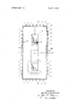
- FIGURE is a schematic diagram of a shielded cylindrical coil in accord with the invention.
- a shielded inductive device represented generally as 20 includes a cylindrical coil 21 and a shield structure 22.
- Cylindrical coil 21 is in the form of a cylinder wherein the windings are confined to the cross-hatched winding area section which has an average winding radius a.
- the winding area also may be said to have a length b and a winding thickness c.
- b c 2a/3 when b c 2a/3, one obtains a so-called Brooks coil which produces maximum inductance for a given length and weight of wire.
- the shield 22 in accordance with the invention, comprises a shield support 23 which may be made of an insulating substance such as a polycarbonate resin or any other suitable non-magnetic and preferably insulating material.
- the dimensions of the support 23, which in general is in the form of a cylindrical pillbox" are such that the diameter is great enough so that the distance from the outwardly depending portion of the cylindrical coil and the inner portion of the shield is greater than a/2 and the length of the support is such that the distance between the longitudinal end of the cylindrical coil and the longitudinal end of the coil support pillbox" structure is also greater than a/2, preferably the same as the lateral distance from the support to the coil.
- Coil l-] is represented by a circle in the upper portion of the diagram with an X indicating therein that the current in the coil flows into the diagram and by a circle symmetrical therewith at the lower portion below the longitudinal axis (represented by Z) having a dot therein indicating the current flows out of the diagram.
- Coil 1-1 is, therefore, a circular coil symmetric about the Z axis or longitudinal axis of the cylindrical coil.
- Coils 2-2 through 5-5 are concentric with coil 1-1 and are likewise concentric and symmetric about the longitudinal axis.
- Image coils, l-l through 5-5' are wound about the opposite longitudinal end 25 of the shield support and are similarly located at similar distances and carry the same currents as coils l-l through 5-5, respectively.
- a plurality of coils 6-6, 7-7 and 88 are wound in the plane of the support cylinder concentric with the longitudinal or Z axis of the cylindrical coil and substantially equi-distant from one another.
- a plurality of image coils 6'-6, 7'-7 and 8'-8 are similarly wound on the opposite side of the cylindrical coil.
- a dotted line extending perpendicular to the longitudinal axis of the coil and to the surface of the cylindrical shield structure represents the X axis and also the X-Y plane, which is a plane of symmetry such that everything that is present on the right or plus side of the plane of symmetry is duplicated identically on the left or minus side of the plane of symmetry.
- each succeeding concentric coil is located at a position having an increment of 3 cm. along the X axis from the preceding coil.
- the coil radii of coils l-l through 5-5 are 6, 9, l2, l5 and l8 cm., corresponding to X coordinates of 6, 9, l2, l5 and 18 all with a Z coordinate of cm.
- the image coils l'-1 through 5- 5' are at coordinate a Z ofl0 and X coordinates of 6, 9, l2, l5 and 18, respectively.
- Coil 8-8 is located at an X coordinate of and a Z coordinate of 1 cm.;
- coil 7-7 is located at an X coordinate of 20 and a Z coordinate of 3 cm.
- coil 66 is located at an X coordinate of 20 and a Z coordinate of 6 centimetersv lmage coils 8', 7' and 6' are respectively at X coordinates of 20 and Z coordinates of -l 3, and 6, respectively.
- the foregoing matrix has the following physical significance.
- the first equation states that the flux produced in flux coil ll" by the unknown currents X, through X, is equal to a value C, which is equal and opposite to the flux C, produced through coil l"-l" by all of the currents in the main coil. The result of the foregoing is to make the total flux, through turn 1 "-1 zero.
- the cross-section of the main coil may be considered to be 5 X 5 equal parts, which may for example, be each a centimeter square.
- a circular turn carrying unit current and having a radius R.
- the effect of this particular 1 ampere current in a parallel plane Z centimeters distance is to produce through a coaxial turn R, centimeter diameter, a flux equal to the followmg:
- the coefficients A are all the sums of pairs of values of fluxes produced through the coil l"l" by a unit current having a value of X, in coils l-l through 8-8 and the image coils on the opposite side of the axis of symmetry.
- the equations then set the condition that the net flux through all coils ll through 8-8 is equal to zero.
- the number of equations solved is equal to the number of symmetrical pairs of coils utilized. A greater or lesser number may be utilized. It is assumed that the same currents pass through the coils on the other side of the axis of symmetry as their counterparts, namely that the current in coil 1'- l' is the same as the current in coil 1-1, for example. If there is no symmetry between l-l and l'-l', etc., 16 equations in the form of those of the above matrix may be formulated instead of the 8 equations based upon symmetry.
- the program submitted for solution by iteration and reiteration may specify that the currents through the shield coils in addition to being identical to one another, be identical with the currents in the main coil. Proper solution of these equations then yields the location of coils which may comprise the shield and which may carry the same current as is carried by the cylindrical coil. Such a specification is particularly desirable since any change in current carried by the cylindrical coil 5 need not require a change in currents or position of the shield since increasing or decreasing of the cylindrical coil current automatically compensates for the flux generated by the shield structure.
- the currentcarrying structure of the cylindrical coil was shown to be equal to an arbitrary size conducting unit.
- the currents X through X utilized herein although represented as a single value of current in a single coil at a precise point, as a practical matter may be implemented by a plurality of wires spanning a finite distance or, in the case of a superconducting field coil and shield by one or more windings of superconducting tape.
- one tape cross-section may be approximately 0.0004 inch thick and approximately 0.5 to 1.5 cm. wide. Several turns of tape may comprise each winding.
- the cylindrical coil is composed of 25 arbitrary current-carrying turns with centers located at points in the Y-Z plane having coordinates varying from Zs of -2 through +2 and Y's varying through 8 to 12 with the center of the cylindrical coil as the origin.
- the shield coils l--l through 8-8 are centered at coordinates in the Y-Z plane of (6,10); (9,10); (12,10); (15,10); (18,10); (20,6); (20,3); and (20,1). With each ofthe cylindrical coil arbitrary conductors carrying a hypothetical current of +1 A (total current of 25 A) the current for each coil is calculated A set of currents obtained is as follows:
- each of the above currents may, as is mentioned before, be a compositeof a set of distributed currents which are arranged about the given point.
- each of currents 1-8 may represent n equal currents symmetrically arranged linearly parallel to the shield support at the region and equidistant from one another along a line of length B centered at the given point.
- each of the eight currents represents 2 equal currents of the following combined values equidistant from one another along a line parallel to the shield support and symmetrical about the point.
- Such values are, for n 2 l. l l 443 8. -0.5791
- n 4 component currents of the following total values are evenly distributed about the point along the line 2 cm. long, as follows:
- a cylindrical inductance coil having a longitudinal axis, an average winding radius, a winding length and a winding thickness
- d. means supplying a current within the respective windings of said shield sufiicient to produce a resultant magnetic flux equal and opposite to to the magnetic flux thereat from said cylindrical coil so that total flux at a point immediately exterior of said shield is substantially zero.
- each of said coils of said first and second plurality of coils is constituted of a plurality of windings having an effective locus at a calculated point.
- each of said coils having a location in an orthogonal system of coordinates based upon said origin;
Abstract
Cylindrical superconductive coil is shielded to provide net zero magnetic field exterior of a cylindrical shield located a predetermined distance from the coil by winding about the shield, and about the ends thereof, winding which carry predetermined currents sufficient to just neutralize the external field due to the current in the coil at the shield.
Description
United States Patent Westendorp I 1 June 20, 1972 [54] SHIELDED INDUCTIVE DEVICE 3,466,499 9/1969 Beth ..33s/214x 3,333,162 7/1967 Arbuthnot.. .336/l8I I721 Invent wes'endm schenecady 2,905,915 9/1959 Harris ..336/l8l [73] Assignee: General Electric Company [22] Filed: May 25, 9 Primary Examiner-Thomas J. Kozma Attorney-John F. Ahem, Paul A. Frank, Jerome C. Squillaro, [2i] Appl. N -r 1 6, Frank L. Neuhauser, Oscar B. Waddell and Joseph B. Forman [52] U.S.Cl ..336/84,335/2l4,335/2l6, 7 A T C 336/l7l,336/l8l,336/DIG. I [5 1 BS M T 51 1m.c|. ..n01r1s 04 Cylindrical superconductive is Shielded to Provide net [58] Field ofSeareh ..336/84, 170, m, 180, 18!, Zero s field exterior of a cylindrical shield located 336/016 335/214 216 predetermined distance from the coil by winding about the shield, and about the ends thereof, winding which carry predetermined currents sufficient to just neutralize the exter- Rehnnces Cited nal field due to the current in the coil at the shield.
UNITED STATES PATENTS 10 Claims, 1 Drawing Figure SHIELDED INDUCTIVE DEVICE This invention relates to shielded inductive devices. More particularly, the invention relates to superconductive reactor coils in the form of a cylinder which are shielded so as to provide substantially no external field during operation.
While it has long been known that the fields existing exterior of an inductive device can be detrimental, the need for such shielding has not been particularly great, nor have means directed to achieving such shielding been particularly successful.
Normally, the field existing exterior of most inductive devices is not very large. Additionally, most inductive devices are complex devices, such as transformers, having primary and secondary windings and the shielding thereof becomes an exceedingly complicated task. Insofar as current is concerned, it has recently been desirable to utilize inductive reactors as storage media for pulsed high energy. Such use requires very high currents and with such currents, external fields may become a problem such as has not been the case in the past. Another use of a coil with a strong magnetic field is a superconducting coil for the field of an acyclic motor or generator, usually called homopolar machines.
In some applications for high current utilization of inductive reactors, particularly wherein size and weight is a factor, superconducting coils are often utilized therefor. In such instances, the currents utilized may be exceedingly high and the magnetic fields resulting therefrom exterior of the coil are of such magnitude that shielding becomes not only desirable but necessary.
It is, therefore, an object of the invention to provide magnetically shielded inductive reactors.
Another object of the invention is to provide superconductive inductive reactors having a simple magnetic shield therefor.
Still another object of the invention is to provide inductive reactors having simple, easily provided means for containing magnetic fields interior thereof.
Yet another object of the invention is to provide a superconducting inductive reactor adequately shielded against stray inductances exterior thereof.
Still another object of the invention is to provide means for determining the precise shielding required to render a given inductive device free of external fields.
Briefly stated, in accord with one embodiment of the invention, I provide a cylindrical inductance coil with a shield comprising a plurality of conductive coils thereabout which surround the coil both laterally and longitudinally along the axis thereof. Both longitudinal and lateral coils are removed from the most closely adjacent portion of the cylindrical coil a predetermined distance. A current is passed through each of the coils of the shield, which currents are just sufficient to produce magnetic fields thereat which are substantially equal and opposite to the magnetic fields caused at the shield by current through the cylindrical coil. In a preferred embodiment, the same current passes through each of the shield coils and is the same magnitude as the current in the windings of the cylindrical coil.
The novel features characteristic of the invention are set forth in the appended claims. The invention itself, together with further objects and advantages thereof, may best be understood by referring to the following detailed description thereof and to the accompanying drawing in which the sole FIGURE is a schematic diagram of a shielded cylindrical coil in accord with the invention.
Most previous attempts to magnetically shield inductive devices have utilized added windings juxtaposed immediately at, or very closely surrounding, the structure of the main inductive device. Such an approach is necessarily doomed to be impracticable and hence unsuccessful. It is well known in the art that magnetic paths must complete a full loop and the flux lines about any inductive device must be completely exterior of the device. Thus, in attempting to shield an inductance device agains the generation of exterior magnetic fields, one
must utilize a shield which is sufficiently remote from the inductive device as to allow for complete flux lines about the device immediately exterior thereof.
In the drawing, a shielded inductive device represented generally as 20 includes a cylindrical coil 21 and a shield structure 22. Cylindrical coil 21 is in the form of a cylinder wherein the windings are confined to the cross-hatched winding area section which has an average winding radius a. The winding area also may be said to have a length b and a winding thickness c. For a coil of the type described herein, when b c 2a/3, one obtains a so-called Brooks coil which produces maximum inductance for a given length and weight of wire. For purposes of construction, it may be more convenient, however, for use in an energy storage inductance, a cylindrical coil in which b c 0/2. Such winding gives nearly maximum inductance and has other advantages. A plurality of flux lines caused by the passage of current through the windings of coil 21 are illustrated in the lower portion of the drawing. It is obvious from the position of the dotted flux lines in the drawing that attempts to shield the flux lines and restrict them to the immediate vicinity of the coil are bound seriously to affect the operating characteristics thereof and, in all probability, be impracticable and unsuccessful. I have determined that a suit"- cient proportion of the flux of the inductive reactor of the type disclosed herein is concentrated within a very close distance to the cylindrical coil such that it is practicable to shield the exterior space around the coil from inductance caused by current within the coil provided that the distance between the exterior portion of the coil and the nearest portion of the shield is at least as great as a/2.
Accordingly, the shield 22, in accordance with the invention, comprises a shield support 23 which may be made of an insulating substance such as a polycarbonate resin or any other suitable non-magnetic and preferably insulating material. The dimensions of the support 23, which in general is in the form of a cylindrical pillbox", are such that the diameter is great enough so that the distance from the outwardly depending portion of the cylindrical coil and the inner portion of the shield is greater than a/2 and the length of the support is such that the distance between the longitudinal end of the cylindrical coil and the longitudinal end of the coil support pillbox" structure is also greater than a/2, preferably the same as the lateral distance from the support to the coil.
Along the longitudinal end 24 of the shield support, a plurality of concentric conductors representing coils ll, 2-2, 3-3, 44 and 5-5 are wound. Coil l-] is represented by a circle in the upper portion of the diagram with an X indicating therein that the current in the coil flows into the diagram and by a circle symmetrical therewith at the lower portion below the longitudinal axis (represented by Z) having a dot therein indicating the current flows out of the diagram. Coil 1-1 is, therefore, a circular coil symmetric about the Z axis or longitudinal axis of the cylindrical coil.
Coils 2-2 through 5-5 are concentric with coil 1-1 and are likewise concentric and symmetric about the longitudinal axis. Image coils, l-l through 5-5' are wound about the opposite longitudinal end 25 of the shield support and are similarly located at similar distances and carry the same currents as coils l-l through 5-5, respectively. Along the cylindrical surface 26 of shield support 23, a plurality of coils 6-6, 7-7 and 88 are wound in the plane of the support cylinder concentric with the longitudinal or Z axis of the cylindrical coil and substantially equi-distant from one another. A plurality of image coils 6'-6, 7'-7 and 8'-8 are similarly wound on the opposite side of the cylindrical coil. For purposes of simplification in measurement, consider the center of the cylindrical coil as the origin in an orthogonal system of coordinates. A dotted line extending perpendicular to the longitudinal axis of the coil and to the surface of the cylindrical shield structure represents the X axis and also the X-Y plane, which is a plane of symmetry such that everything that is present on the right or plus side of the plane of symmetry is duplicated identically on the left or minus side of the plane of symmetry.
In order to determine the exact position of, and currents through each of the coils comprising the shield structure which are sufficient to cancel out the exterior field thereat caused by the current in the cylindrical coil, one may undertake the following mathematical exercise. Consider that an unknown current X, exists in coil l-l (and also l-l as well) and an unknown current exists in each of the coils up to current X in coil 8-8 (and 8-8' as well).
It is necessary then to assume an arbitrary size and shape of main coil and arbitrary positions of shield members to arrive at a first approximation of currents and positions by mathematical analysis. One may proceed as follows. Arbitrarily, assume a cylindrical coil having a mean radius a of 10 cm., a length b of cm. and a winding depth 0, also of5 cm. Assume a shield structure coaxial and concentric with the main coil and having a radius of 20 cm. and a length of 20 cm. The eight coils l-l through 8-8 are positioned as is described hereinbefore along the X and Z axes with coil l-l at a Z dimension of lO cm. and an X dimension of 6 cm., each succeeding concentric coil is located at a position having an increment of 3 cm. along the X axis from the preceding coil. Thus, the coil radii of coils l-l through 5-5 are 6, 9, l2, l5 and l8 cm., corresponding to X coordinates of 6, 9, l2, l5 and 18 all with a Z coordinate of cm. The image coils l'-1 through 5- 5' are at coordinate a Z ofl0 and X coordinates of 6, 9, l2, l5 and 18, respectively. Coil 8-8 is located at an X coordinate of and a Z coordinate of 1 cm.; coil 7-7 is located at an X coordinate of 20 and a Z coordinate of 3 cm. and coil 66 is located at an X coordinate of 20 and a Z coordinate of 6 centimetersv lmage coils 8', 7' and 6' are respectively at X coordinates of 20 and Z coordinates of - l 3, and 6, respectively.
To satisfy the criterion that the flux exterior of a shield is essentially zero, one assumes a plurality of 8 hypothetical circles or coils exterior of the shield and closely juxtaposed thereat. These are represented by coils l"l, 2"-2", through 8"-8" which are located symmetrically along a hypothetical surface so that all coils are larger by 1.5 cm. in both X and Z dimensions than the shield support member 23. In order to satisfy the criterion of perfect shielding, it is required that the each of the 8 magnetic fluxes through the circles defined by l"- l through 8"8" is zero. While for any given circle, it may be that a positive flux may exist through, say the center thereof, in one direction, a negative flux must then appear as an annalus thereabout at a greater radius section and the total flux through the circle must be zero.
Utilizing the terms A to represent the coefficients of mutual inductance between specific coils l-l through 8-8 with particular circles l"-l" through 8-8" and X,, to be the current in coils 1-1 through 8-8. Eight equations in form of r 2 u r= a representing a sum of the total flux through a given coil due to currents through the shield coils are set up to form a matrix of eight equations in the following form:
zero.
The foregoing matrix has the following physical significance. The first equation states that the flux produced in flux coil ll" by the unknown currents X, through X, is equal to a value C, which is equal and opposite to the flux C, produced through coil l"-l" by all of the currents in the main coil. The result of the foregoing is to make the total flux, through turn 1 "-1 zero.
The cross-section of the main coil may be considered to be 5 X 5 equal parts, which may for example, be each a centimeter square. Through the center of each one of the subdivisions, one may assume a circular turn carrying unit current and having a radius R. The effect of this particular 1 ampere current in a parallel plane Z centimeters distance is to produce through a coaxial turn R, centimeter diameter, a flux equal to the followmg:
F= 0.4 1r (R R,) [(2/QQ)K 2E/Q]Maxwells where K and E are the complete elliptic integrals of the first and second kind of argument Q and In these calculations, the term 0.4 tr, which is the relationship between flux and current, has been omitted since the relative values of flux, only, are of importance. The right-hand side of the first equation of the matrix, i.e., C, then becomes the negative sum of 25 fluxes produced by the 25 substitute turns of the main cylindrical coil through flux measuring turn 1"l". Similarly, the coefficients A,,, are all the sums of pairs of values of fluxes produced through the coil l"l" by a unit current having a value of X, in coils l-l through 8-8 and the image coils on the opposite side of the axis of symmetry. The equations then set the condition that the net flux through all coils ll through 8-8 is equal to zero.
These equations, when solved, produce the values of current (X) necessary for given positions to achieve complete flux cancellation. Should the solution be unsatisfactory by the empirically chosen positions of coils l-l through 88, new positions are chosen and the equations resolved by iteration and reiteration. Finally, with an appropriate number of solutions of the equations of the matrix, both the values of the currents and the positions of the coils 1-1 through 88 are obtained.
Although it is possible to solve the foregoing equations by conventional means, modern computer technology makes the formulation of a simple program for the solution of the equations by iteration and reiteration utilizing a business computer a simple matter and one which is well known to those skilled in the art for the near-instantaneous solution of the equations to obtain the values of position and currents necessary to provide cancellation of the flux caused by the cylindrical coil at the surface of the shield such as to provide substantially a fieldfree space exterior thereof.
The number of equations solved is equal to the number of symmetrical pairs of coils utilized. A greater or lesser number may be utilized. It is assumed that the same currents pass through the coils on the other side of the axis of symmetry as their counterparts, namely that the current in coil 1'- l' is the same as the current in coil 1-1, for example. If there is no symmetry between l-l and l'-l', etc., 16 equations in the form of those of the above matrix may be formulated instead of the 8 equations based upon symmetry.
It is also possible, by solution of the equations of the matrix by iteration and reiteration to specify in the program that the ampere turns of the coils l-l through 8-8, namely, X, through X,,, and proportional to the turns used in each of 1-1 through 88, and that the same current flow in all coils of the shield. A solution by the computer of equations with this specified makes possible the fabrication of a single conductive structure with however, the requirement that current passed to and from each of coils l-l through 88 must be brought into the shield so as not to be cut by the lines of flux, causing perturbations of the currents therein. A helical structure is not contemplated in this structure. It is further possible that the program submitted for solution by iteration and reiteration may specify that the currents through the shield coils in addition to being identical to one another, be identical with the currents in the main coil. Proper solution of these equations then yields the location of coils which may comprise the shield and which may carry the same current as is carried by the cylindrical coil. Such a specification is particularly desirable since any change in current carried by the cylindrical coil 5 need not require a change in currents or position of the shield since increasing or decreasing of the cylindrical coil current automatically compensates for the flux generated by the shield structure.
As is noted hereinbefore, for convenience sake, the currentcarrying structure of the cylindrical coil was shown to be equal to an arbitrary size conducting unit. Similarly, the currents X through X utilized herein, although represented as a single value of current in a single coil at a precise point, as a practical matter may be implemented by a plurality of wires spanning a finite distance or, in the case of a superconducting field coil and shield by one or more windings of superconducting tape. 1n the case of a superconducting tape of Nb sn, for example, one tape cross-section may be approximately 0.0004 inch thick and approximately 0.5 to 1.5 cm. wide. Several turns of tape may comprise each winding.
One set of currents for coils of a shield for the cylindrical coil, the dimensions of which were given above, was determined by solving the above equations utilizing a simple program in Basic language on a GE 600 computer. The cylindrical coil is composed of 25 arbitrary current-carrying turns with centers located at points in the Y-Z plane having coordinates varying from Zs of -2 through +2 and Y's varying through 8 to 12 with the center of the cylindrical coil as the origin. The shield coils l--l through 8-8 are centered at coordinates in the Y-Z plane of (6,10); (9,10); (12,10); (15,10); (18,10); (20,6); (20,3); and (20,1). With each ofthe cylindrical coil arbitrary conductors carrying a hypothetical current of +1 A (total current of 25 A) the current for each coil is calculated A set of currents obtained is as follows:
8. 0.538471 Each of the above currents may, as is mentioned before, be a compositeof a set of distributed currents which are arranged about the given point. Thus, each of currents 1-8 may represent n equal currents symmetrically arranged linearly parallel to the shield support at the region and equidistant from one another along a line of length B centered at the given point.
As an example of the above, when B 2 cm. and n 2, each of the eight currents, above, represents 2 equal currents of the following combined values equidistant from one another along a line parallel to the shield support and symmetrical about the point. Such values are, for n 2 l. l l 443 8. -0.5791 Similarly, when n 4, 4 component currents of the following total values are evenly distributed about the point along the line 2 cm. long, as follows:
Similarly, when n 8, 8 component currents of the following total values are evenly distributed about the points along a line 2 cm. long as follows:
1. --1.1431 2. 1. 1819 3. 1.1025 4. 0.65 3 5. 0.2849 6. 0.6159 7. 0.6398 8. 0.587 By the foregoing, l have indicated that if n becomes large only the total number of ampere turns distributed over the Y dimension B= 2 cm. becomes a constant number and for each shield coil a number of turnsmay be chosen so that the same current may be used in the shield and main coils fulfilling the ampere turn requirement.
Also, by the foregoing, l have described a simple system for providing, and have provided a simple, yet effective magnetic shield for an electromagnetic coil such as substantially to prevent the existence of stray fields due to current through the coil exterior of a point that is a predetermined distance from the coil exterior sufficient to prevent flux leakage about the exterior thereof.
While the invention has been set forth in terms of certain examples and embodiments thereof, many modifications and changes will readily occur to those skilled in the art.
Accordingly, by the appended claims, I intend to cover all such changes as fall within the true intent and scope of the disclosure.
What 1 claim as new and desire to secure by Letters Patent of the United States is:
1. A magnetically shielded inductive device which exhibits no effective magnetic flux exterior thereof and comprising:
a. a cylindrical inductance coil having a longitudinal axis, an average winding radius, a winding length and a winding thickness; b. a magnetic shield surrounding said cylindrical coil and comprising, b first and second sets of concentric windings concentric with said longitudinal axis and with one another disposed in two planes normal to said axis at each end of said cylindrical coil and at a first predetermined distance from either end thereof; 0
11;. a second plurality of windings concentric with said axis and lying in a cylindrical surface between the planes of said first and second sets of concentric windings and laterally surrounding said cylindrical coil;
c. the windings of said shield being disposed from the exterior of said cylindrical coil in all directions a distance of at least half said average winding radius; and
d. means supplying a current within the respective windings of said shield sufiicient to produce a resultant magnetic flux equal and opposite to to the magnetic flux thereat from said cylindrical coil so that total flux at a point immediately exterior of said shield is substantially zero.
2. The device of claim 1 wherein the currents in each of the said pluralities of windings are independently established at individual values.
3. The device of claim 1 wherein the currents in each of said windings are equal to one another.
4. The device of claim 3 wherein said windings are connected for common current flow.
5. The device of claim 4 wherein said current in said windings is identical with current in the windings of said cylindrical coil.
6. The device of claim 5 wherein said shield windings and said cylindrical coil windings are connected for common cur rent flow.
7. The device of claim I wherein said cylindrical windings and said shield coils are of superconducting material.
8. The device of claim 7 wherein said material is Nb Sn.
9. The device of claim 1 wherein each of said coils of said first and second plurality of coils is constituted of a plurality of windings having an effective locus at a calculated point.
10. A method of providing a magnetic shield in the form of a cylindrical array of circular coils about a cylindrical inductance coil which shield is effective to substantially neutralize leakage flux from said cylindrical coil at the surface of said shield which method comprises:
a. establishing an origin of coordinates at the center of a cylindrical coil having an average winding radius of a, a winding thickness of b, and a winding length ofc;
. locating a first plurality of two n circular shield coils symmetrically located about the ends and cylindrical surface of said cylindrical shield,
b,. each of said coils having a location in an orthogonal system of coordinates based upon said origin;
c. establishing a second plurality of hypothetical coils equal in number to said first plurality of circular coils and exterior thereof in said coordinate system;
d establishing a plurality of n equations having n terms each of the form where A is a coefficient of mutual inductance between first circular coils and hypothetical coils, i and j are indices of individual circular and hypothetical coils respectively, X is the current in a particular indicated circular coil of the shield, and C is the flux at the jth hypothetical coil due to
Claims (10)
1. A magnetically shielded inductive device which exhibits no effective magnetic flux exterior thereof and comprising: a. a cylindrical inductance coil having a longitudinal axis, an average winding radius, a winding length and a winding thickness; b. a magnetic shield surrounding said cylindrical coil and comprising, b1. first and second sets of concentric windings concentric with said longitudinal axis and with one another disposed in two planes normal to said axis at each end of said cylindrical coil and at a first predetermined distance from either end thereof; b2. a second plurality of windings concentric with said axis and lying in a cylindrical surface between the planes of said first and second sets of concentric windings and laterally surrounding said cylindrical coil; c. the windings of said shield being disposed from the exterior of said cylindrical coil in all directions a distance of at least half said average winding radius; and d. means supplying a current within the respective windings of said shield sufficient to produce a resultant magnetic flux equal and opposite to the magnetic flux thereat from said cylindrical coil so that total flux at a point immediately exterior of said shield is substantially zero.
2. The device of claim 1 wherein the currents in each of the said pluralities of windings are independently established at individual values.
3. The device of claim 1 wherein the currents in each of said windings are equal to one another.
4. The device of claim 3 wherein said windings are connected for common current flow.
5. The device of claim 4 wherein said current in said windings is identical with current in the windings of said cylindrical coil.
6. The device of claim 5 wherein said shield windings and said cylindrical coil windings are connected for common current flow.
7. The device of claim 1 wherein said cylindrical windings and said shield coils are of superconducting material.
8. The device of claim 7 wherein said material is Nb3Sn.
9. The device of claim 1 wherein each of said coils of said first and second plurality of coils is constituted of a plurality of windings having an effective locus at a calculated point.
10. A method of providing a magNetic shield in the form of a cylindrical array of circular coils about a cylindrical inductance coil which shield is effective to substantially neutralize leakage flux from said cylindrical coil at the surface of said shield which method comprises: a. establishing an origin of coordinates at the center of a cylindrical coil having an average winding radius of a, a winding thickness of b, and a winding length of c; b. locating a first plurality of two n circular shield coils symmetrically located about the ends and cylindrical surface of said cylindrical shield, b1. each of said coils having a location in an orthogonal system of coordinates based upon said origin; c. establishing a second plurality of hypothetical coils equal in number to said first plurality of circular coils and exterior thereof in said coordinate system; d. establishing a plurality of n equations having n terms each of the form where A is a coefficient of mutual inductance between first circular coils and hypothetical coils, i and j are indices of individual circular and hypothetical coils respectively, X is the current in a particular indicated circular coil of the shield, and C is the flux at the jth hypothetical coil due to current in the cylindrical coil; e. solving said equations for the respective currents; and f. modifying the position of respective circular shield coils and repeating steps a - e until said currents are optimum.
Applications Claiming Priority (1)
| Application Number | Priority Date | Filing Date | Title |
|---|---|---|---|
| US14669671A | 1971-05-25 | 1971-05-25 |
Publications (1)
| Publication Number | Publication Date |
|---|---|
| US3671902A true US3671902A (en) | 1972-06-20 |
Family
ID=22518569
Family Applications (1)
| Application Number | Title | Priority Date | Filing Date |
|---|---|---|---|
| US146696A Expired - Lifetime US3671902A (en) | 1971-05-25 | 1971-05-25 | Shielded inductive device |
Country Status (1)
| Country | Link |
|---|---|
| US (1) | US3671902A (en) |
Cited By (17)
| Publication number | Priority date | Publication date | Assignee | Title |
|---|---|---|---|---|
| US4032959A (en) * | 1974-12-18 | 1977-06-28 | Wisconsin Alumni Research Foundation | Shielded superconducting inductor device |
| EP0144171A1 (en) * | 1983-11-11 | 1985-06-12 | Oxford Advanced Technology Limited | Magnet assembly |
| US4595899A (en) * | 1984-07-06 | 1986-06-17 | The Board Of Trustees Of The Leland Stanford Junior University | Magnetic structure for NMR applications and the like |
| US4651117A (en) * | 1984-11-07 | 1987-03-17 | Mitsubishi Denki Kabushiki Kaisha | Superconducting magnet with shielding apparatus |
| JPS62143012A (en) * | 1985-09-20 | 1987-06-26 | ブリティッシュ・テクノロジー・グループ・リミテッド | Magnetic shield |
| GB2193322A (en) * | 1986-06-28 | 1988-02-03 | Nat Res Dev | Magnetic field coils |
| GB2193323A (en) * | 1986-06-26 | 1988-02-03 | Nat Res Dev | Electrical coils |
| DE3891385T1 (en) * | 1988-09-08 | 1990-08-30 | Mitsubishi Electric Corp | SUPRALOWING MAGNETIC DEVICE |
| US5159261A (en) * | 1989-07-25 | 1992-10-27 | Superconductivity, Inc. | Superconducting energy stabilizer with charging and discharging DC-DC converters |
| US5376828A (en) * | 1991-07-01 | 1994-12-27 | Superconductivity, Inc. | Shunt connected superconducting energy stabilizing system |
| US5530355A (en) * | 1993-05-13 | 1996-06-25 | Doty Scientific, Inc. | Solenoidal, octopolar, transverse gradient coils |
| US5554929A (en) * | 1993-03-12 | 1996-09-10 | Doty Scientific, Inc. | Crescent gradient coils |
| US5576622A (en) * | 1991-11-14 | 1996-11-19 | Fonar Corporation | Shielded NMR radio frequency coil and method of performing an NMR experiment |
| EP0749017A1 (en) * | 1986-02-06 | 1996-12-18 | General Electric Company | Self-shielded gradient coils for nuclear magnetic resonance imaging |
| USRE36782E (en) * | 1983-11-11 | 2000-07-18 | Oxford Medical Limited | Magnet assembly for use in NMR apparatus |
| US20090206976A1 (en) * | 2006-05-19 | 2009-08-20 | Lars-Tommy Andersson | Reactor shield |
| US20100321138A1 (en) * | 2006-12-28 | 2010-12-23 | Kyushu University, National University Corporation | Separate type magnetic shield apparatus |
Citations (4)
| Publication number | Priority date | Publication date | Assignee | Title |
|---|---|---|---|---|
| US2714710A (en) * | 1949-07-23 | 1955-08-02 | Philco Corp | Transformer |
| US2905915A (en) * | 1954-01-22 | 1959-09-22 | Harris Transducer Corp | Compensated transformer |
| US3333162A (en) * | 1964-01-23 | 1967-07-25 | Iii Guy L Arbuthnot | Solenoid actuator |
| US3466499A (en) * | 1967-03-27 | 1969-09-09 | Atomic Energy Commission | Cancellation of external magnetic fields by inner and outer cylindrical current sheets |
-
1971
- 1971-05-25 US US146696A patent/US3671902A/en not_active Expired - Lifetime
Patent Citations (4)
| Publication number | Priority date | Publication date | Assignee | Title |
|---|---|---|---|---|
| US2714710A (en) * | 1949-07-23 | 1955-08-02 | Philco Corp | Transformer |
| US2905915A (en) * | 1954-01-22 | 1959-09-22 | Harris Transducer Corp | Compensated transformer |
| US3333162A (en) * | 1964-01-23 | 1967-07-25 | Iii Guy L Arbuthnot | Solenoid actuator |
| US3466499A (en) * | 1967-03-27 | 1969-09-09 | Atomic Energy Commission | Cancellation of external magnetic fields by inner and outer cylindrical current sheets |
Cited By (30)
| Publication number | Priority date | Publication date | Assignee | Title |
|---|---|---|---|---|
| US4032959A (en) * | 1974-12-18 | 1977-06-28 | Wisconsin Alumni Research Foundation | Shielded superconducting inductor device |
| USRE36782E (en) * | 1983-11-11 | 2000-07-18 | Oxford Medical Limited | Magnet assembly for use in NMR apparatus |
| EP0144171A1 (en) * | 1983-11-11 | 1985-06-12 | Oxford Advanced Technology Limited | Magnet assembly |
| EP0251342A3 (en) * | 1983-11-11 | 1988-11-17 | Oxford Medical Limited | Magnet assembly |
| EP0251342A2 (en) * | 1983-11-11 | 1988-01-07 | Oxford Medical Limited | Magnet assembly |
| US4595899A (en) * | 1984-07-06 | 1986-06-17 | The Board Of Trustees Of The Leland Stanford Junior University | Magnetic structure for NMR applications and the like |
| US4651117A (en) * | 1984-11-07 | 1987-03-17 | Mitsubishi Denki Kabushiki Kaisha | Superconducting magnet with shielding apparatus |
| JPS62143012A (en) * | 1985-09-20 | 1987-06-26 | ブリティッシュ・テクノロジー・グループ・リミテッド | Magnetic shield |
| GB2221540A (en) * | 1985-09-20 | 1990-02-07 | Nat Res Dev | Magnetic field screens |
| EP0365065A1 (en) * | 1985-09-20 | 1990-04-25 | Btg International Limited | Magnetic field screens |
| GB2180943B (en) * | 1985-09-20 | 1990-07-04 | Nat Res Dev | Magnetic field screens |
| US4978920A (en) * | 1985-09-20 | 1990-12-18 | National Research Development Corporation | Magnetic field screens |
| EP0749017A1 (en) * | 1986-02-06 | 1996-12-18 | General Electric Company | Self-shielded gradient coils for nuclear magnetic resonance imaging |
| GB2193323A (en) * | 1986-06-26 | 1988-02-03 | Nat Res Dev | Electrical coils |
| GB2193323B (en) * | 1986-06-26 | 1991-03-27 | Nat Res Dev | Electrical coils |
| GB2193322B (en) * | 1986-06-28 | 1991-02-20 | Nat Res Dev | Magnetic field coils |
| GB2193322A (en) * | 1986-06-28 | 1988-02-03 | Nat Res Dev | Magnetic field coils |
| DE3891385T1 (en) * | 1988-09-08 | 1990-08-30 | Mitsubishi Electric Corp | SUPRALOWING MAGNETIC DEVICE |
| US5159261A (en) * | 1989-07-25 | 1992-10-27 | Superconductivity, Inc. | Superconducting energy stabilizer with charging and discharging DC-DC converters |
| US5376828A (en) * | 1991-07-01 | 1994-12-27 | Superconductivity, Inc. | Shunt connected superconducting energy stabilizing system |
| US5514915A (en) * | 1991-07-01 | 1996-05-07 | Superconductivity, Inc. | Shunt connected superconducting energy stabilizing system |
| US5576622A (en) * | 1991-11-14 | 1996-11-19 | Fonar Corporation | Shielded NMR radio frequency coil and method of performing an NMR experiment |
| US5554929A (en) * | 1993-03-12 | 1996-09-10 | Doty Scientific, Inc. | Crescent gradient coils |
| US5886548A (en) * | 1993-03-12 | 1999-03-23 | Doty Scientific Inc. | Crescent gradient coils |
| US5530355A (en) * | 1993-05-13 | 1996-06-25 | Doty Scientific, Inc. | Solenoidal, octopolar, transverse gradient coils |
| US20090206976A1 (en) * | 2006-05-19 | 2009-08-20 | Lars-Tommy Andersson | Reactor shield |
| CN101443861B (en) * | 2006-05-19 | 2011-09-28 | Abb技术有限公司 | Shield for reactor |
| US8659380B2 (en) * | 2006-05-19 | 2014-02-25 | Abb Technology Ltd. | Reactor shield |
| US20100321138A1 (en) * | 2006-12-28 | 2010-12-23 | Kyushu University, National University Corporation | Separate type magnetic shield apparatus |
| US8031039B2 (en) * | 2006-12-28 | 2011-10-04 | Kyushu University, National University Corporation | Separate type magnetic shield apparatus |
Similar Documents
| Publication | Publication Date | Title |
|---|---|---|
| US3671902A (en) | Shielded inductive device | |
| US4740758A (en) | Apparatus for generating a magnetic field in a volume having bodies influencing the field pattern | |
| Golay | Field homogenizing coils for nuclear spin resonance instrumentation | |
| US4595899A (en) | Magnetic structure for NMR applications and the like | |
| Goodzeit et al. | The double-helix dipole-a novel approach to accelerator magnet design | |
| US3466499A (en) | Cancellation of external magnetic fields by inner and outer cylindrical current sheets | |
| CA1303155C (en) | Electromagnetic shield for electromagnetic apparatus | |
| Daneshmand et al. | Hysteresis loss improvement in HTS transformers using hybrid winding schemes | |
| Wolf | Persistent currents in LHC magnets | |
| US3173116A (en) | Electrical apparatus having magnetic and non-magnetic shielding | |
| Evans et al. | Losses in foil-wound secondaries in high-frequency transformers | |
| US3423706A (en) | Multipole magnet having a sequentially shim stepped coil configuration | |
| US3290634A (en) | Magnetically shielded transformer | |
| Gustafson | Magnetic shielding of transformers at audio frequencies | |
| US3159804A (en) | Winding transposition | |
| Morgillo et al. | Superconducting 8 cm corrector magnets for the relativistic heavy ion collider (RHIC) | |
| Brammer et al. | Magnetic shielding of small high power SMES | |
| Toral et al. | Comparison of 2-D magnetic designs of selected coil configurations for the Next European Dipole (NED) | |
| Meuser | Secondary Beam Magnets for the 200-Bev Accelerator--Conventional or Superconducting? | |
| JPH0570921B2 (en) | ||
| Fresacher et al. | Actively shielded transportable SMES-systems | |
| Hassenzahl et al. | Field quality of the end sections of SSC dipoles | |
| Vogel et al. | Study on diffusion of the vertical magnetic field in the toroidal stabilizing shell and plasma of the ZT-40M reversed field pinch device | |
| KR900007796Y1 (en) | Shield for electronic devices | |
| Lundy et al. | High gradient superconducting quadrupoles |