EP2481918A1 - Method for operating a wind farm in a RADAR neighbourhood - Google Patents
Method for operating a wind farm in a RADAR neighbourhood Download PDFInfo
- Publication number
- EP2481918A1 EP2481918A1 EP20110152546 EP11152546A EP2481918A1 EP 2481918 A1 EP2481918 A1 EP 2481918A1 EP 20110152546 EP20110152546 EP 20110152546 EP 11152546 A EP11152546 A EP 11152546A EP 2481918 A1 EP2481918 A1 EP 2481918A1
- Authority
- EP
- European Patent Office
- Prior art keywords
- rotor
- axis
- radar system
- determining
- value
- Prior art date
- Legal status (The legal status is an assumption and is not a legal conclusion. Google has not performed a legal analysis and makes no representation as to the accuracy of the status listed.)
- Granted
Links
- 238000000034 method Methods 0.000 title claims abstract description 24
- 230000001105 regulatory effect Effects 0.000 abstract 1
- 230000033001 locomotion Effects 0.000 description 12
- 230000006870 function Effects 0.000 description 8
- 238000001556 precipitation Methods 0.000 description 7
- 230000001419 dependent effect Effects 0.000 description 3
- 230000000694 effects Effects 0.000 description 3
- 238000004519 manufacturing process Methods 0.000 description 3
- 229910000831 Steel Inorganic materials 0.000 description 2
- 238000001514 detection method Methods 0.000 description 2
- 239000011513 prestressed concrete Substances 0.000 description 2
- 239000007787 solid Substances 0.000 description 2
- 239000010959 steel Substances 0.000 description 2
- 230000002411 adverse Effects 0.000 description 1
- 238000006243 chemical reaction Methods 0.000 description 1
- 238000010276 construction Methods 0.000 description 1
- 238000013461 design Methods 0.000 description 1
- 230000001627 detrimental effect Effects 0.000 description 1
- 238000011161 development Methods 0.000 description 1
- 230000018109 developmental process Effects 0.000 description 1
- 230000005670 electromagnetic radiation Effects 0.000 description 1
- 238000011156 evaluation Methods 0.000 description 1
- 238000009434 installation Methods 0.000 description 1
- 239000000463 material Substances 0.000 description 1
- 238000005259 measurement Methods 0.000 description 1
- 238000012544 monitoring process Methods 0.000 description 1
- NJPPVKZQTLUDBO-UHFFFAOYSA-N novaluron Chemical compound C1=C(Cl)C(OC(F)(F)C(OC(F)(F)F)F)=CC=C1NC(=O)NC(=O)C1=C(F)C=CC=C1F NJPPVKZQTLUDBO-UHFFFAOYSA-N 0.000 description 1
- 230000008447 perception Effects 0.000 description 1
- 230000010363 phase shift Effects 0.000 description 1
- 238000012545 processing Methods 0.000 description 1
- 230000001902 propagating effect Effects 0.000 description 1
- 230000002123 temporal effect Effects 0.000 description 1
- 230000003313 weakening effect Effects 0.000 description 1
Images

Classifications
-
- F—MECHANICAL ENGINEERING; LIGHTING; HEATING; WEAPONS; BLASTING
- F03—MACHINES OR ENGINES FOR LIQUIDS; WIND, SPRING, OR WEIGHT MOTORS; PRODUCING MECHANICAL POWER OR A REACTIVE PROPULSIVE THRUST, NOT OTHERWISE PROVIDED FOR
- F03D—WIND MOTORS
- F03D7/00—Controlling wind motors
- F03D7/02—Controlling wind motors the wind motors having rotation axis substantially parallel to the air flow entering the rotor
- F03D7/0204—Controlling wind motors the wind motors having rotation axis substantially parallel to the air flow entering the rotor for orientation in relation to wind direction
-
- F—MECHANICAL ENGINEERING; LIGHTING; HEATING; WEAPONS; BLASTING
- F05—INDEXING SCHEMES RELATING TO ENGINES OR PUMPS IN VARIOUS SUBCLASSES OF CLASSES F01-F04
- F05B—INDEXING SCHEME RELATING TO WIND, SPRING, WEIGHT, INERTIA OR LIKE MOTORS, TO MACHINES OR ENGINES FOR LIQUIDS COVERED BY SUBCLASSES F03B, F03D AND F03G
- F05B2260/00—Function
- F05B2260/99—Radar absorption
-
- Y—GENERAL TAGGING OF NEW TECHNOLOGICAL DEVELOPMENTS; GENERAL TAGGING OF CROSS-SECTIONAL TECHNOLOGIES SPANNING OVER SEVERAL SECTIONS OF THE IPC; TECHNICAL SUBJECTS COVERED BY FORMER USPC CROSS-REFERENCE ART COLLECTIONS [XRACs] AND DIGESTS
- Y02—TECHNOLOGIES OR APPLICATIONS FOR MITIGATION OR ADAPTATION AGAINST CLIMATE CHANGE
- Y02E—REDUCTION OF GREENHOUSE GAS [GHG] EMISSIONS, RELATED TO ENERGY GENERATION, TRANSMISSION OR DISTRIBUTION
- Y02E10/00—Energy generation through renewable energy sources
- Y02E10/70—Wind energy
- Y02E10/72—Wind turbines with rotation axis in wind direction
-
- Y—GENERAL TAGGING OF NEW TECHNOLOGICAL DEVELOPMENTS; GENERAL TAGGING OF CROSS-SECTIONAL TECHNOLOGIES SPANNING OVER SEVERAL SECTIONS OF THE IPC; TECHNICAL SUBJECTS COVERED BY FORMER USPC CROSS-REFERENCE ART COLLECTIONS [XRACs] AND DIGESTS
- Y10—TECHNICAL SUBJECTS COVERED BY FORMER USPC
- Y10T—TECHNICAL SUBJECTS COVERED BY FORMER US CLASSIFICATION
- Y10T29/00—Metal working
- Y10T29/49—Method of mechanical manufacture
- Y10T29/49316—Impeller making
Definitions
- the invention relates to a method for operating a wind turbine and an arrangement with such a wind turbine, which is configured to carry out the method.
- the invention further relates to a system with such an arrangement and a radar system, in particular a weather radar system or an air traffic control radar system.
- Weather radar systems are used to detect precipitation, intensity and movement of precipitation systems, to determine the type of precipitation (for example rain, snow, hail), as well as to predict the temporal and spatial evolution of precipitation systems.
- Air traffic control radar systems are used to monitor air traffic.
- Radar systems emit directional primary signals of pulsed electromagnetic radiation in the S-band or L-band of the microwave range.
- the primary signals are generated by means of a pulse magnetron or a klystron tube, which is connected via a waveguide to a parabolic antenna, which is provided both as a transmitting and as a receiving device.
- the electromagnetic pulses radiate out from the radar station radially at a solid angle ⁇ and become in themselves at that solid angle Reflected objects such as rainfall systems, terrain surveys, aircraft, or other anthropogenic objects. Between the individual pulses, the radar station serves as a receiver for reflected secondary signals.
- the horizontal distance of a reflecting object can be determined from the transit time of the reflected electromagnetic wave propagating at the speed of light in the pulse volume.
- the speed of reflecting objects can be derived from (successive) pulses ((pulse) Doppler radar).
- the radial Doppler velocity of the scatterer results from the correlation of the intensities of successively detected secondary pulses.
- the tangential velocity of the spreader with respect to the radar station can be derived from the radial projection of the tangential velocity from scattered signals detected in adjacent angular ranges.
- Wind turbines can have a detrimental effect on the evaluation accuracy of radar systems. Due to the rotational movement of the rotor blades and the wind-dependent changing profile wind turbines generate stray signals that can be misinterpreted by radar systems. If wind turbines are aligned according to a wind direction, which is rotated by approximately 90 ° with respect to the direction of incidence of a radar pulse, the scattering of the moving rotor blades can cause doublets of Speed signatures emerge that resemble natural weather conditions and critical ones Weather conditions can lead to misinterpretations and inaccurate short-term weather forecasts. Likewise, such spurious signals adversely affect the detection of Aircraft and the determination of their trajectories. Furthermore, weather systems located leeward with respect to the direction of incidence are obscured by wind turbines, which leads to a weakening of the intensity of the secondary signals of such weather systems and makes them worse valued in terms of their precipitation intensity.
- the WO 2010/122350 A1 and WO 2010/109174 A1 describe the use of a rotor blade or a method for producing a rotor blade for a wind energy plant using an electromagnetic absorbing tissue with the aim of reducing the radar signature of wind turbines.
- the production requires additional processing steps and materials that lead to an increase in manufacturing costs in rotor blade construction.
- the WO 2010/099773 A1 describes a method for detecting wind turbines using a radar system. Only wind turbines are identified as sources of interference and localized.
- a method of operating a wind turbine includes providing a wind turbine.
- the wind turbine has a longitudinally extended stand device, in particular a tower, for example designed as a steel tube, prestressed concrete, truss or sandwich tower, as well as a rotatably mounted on the stand device generator.
- the generator is coupled via a rotor hub with a rotor and a rotor hub.
- the rotor has at least one elongated rotor blade.
- a position of a radar system with respect to the wind turbine is determined.
- An area for the axis of rotation of the rotor in the direction of the generator is determined as a function of the determined position, which is not to be permanently assumed when the rotor shaft is aligned about the longitudinal axis of the stationary device.
- the area is avoided in which the movement of the rotor greatly influences the radar system. If the axis of rotation of the rotor is rotated about the longitudinal axis of the stand device, in particular in order to optimally align the rotor depending on a measured wind direction, the area should not be taken permanently, in which the movement of the rotor greatly influences the radar system.
- the area that is avoided corresponds to the area that should not be permanently occupied.
- the area which is not to be permanently occupied may be passed through with an orientation of the axis of rotation of the rotor depending on a wind direction.
- a period is given for which the Rotation axis of the rotor may be aligned in the area.
- a position within the range longer than the predetermined period is not taken.
- the period is predetermined, for example, as a function of a speed with which the axis of rotation of the rotor can be aligned.
- the axis of rotation of the rotor corresponds in particular to the longitudinal axis of a rotor shaft.
- the radar system is in particular a weather radar system for the detection of weather systems or a radar system for air traffic control.
- a weather radar system for the detection of weather systems or a radar system for air traffic control.
- at least two areas are avoided in which the movement of the rotor in the radar system triggers perceptions that are similar to weather phenomena.
- the wind power plant can be operated in the effective range of one or more radar systems with simultaneous reliable operation of the radar system.
- the area which is not to be permanently occupied in the alignment of the axis of rotation of the rotor is determined in dependence on a straight line on which the radar system and the rotor hub lie.
- the straight line is an imaginary direct connecting line between the radar system and the rotor hub.
- the effective range of the radar system is in particular an area around this straight line.
- an absolute geographic coordinate is specified, for example, the north direction at the location of the wind turbine.
- the area is determined which should not be permanently taken during the alignment.
- a wind direction is determined in which an optimal orientation lies in the region to be avoided, in embodiments the rotational axis of the rotor is aligned with the edge of the region to be avoided.
- an operation with oblique flow in which the rotor shaft is not optimally aligned in the wind direction, should be largely avoided, since during such operation in oblique flow, the mechanical load on the wind turbine, especially on bearings and gearbox, is higher than optimal Orientation in the wind direction.
- the wind energy plant is operated in oblique flow.
- the axis of rotation of the rotor is aligned with the edge of the region at which the oblique flow is minimal, in particular compared to the other edge of the range.
- a value for an actual speed of the rotor is determined, in particular immediately before the area to be avoided is traversed.
- a second value for the speed of the rotor is specified.
- the second value for the speed is particularly dependent on the radar system and is chosen so that the rotation of the rotor at a speed of less than or equal to the second value the radar system not or only slightly affected.
- the second value corresponds to an idling operation of the wind power plant, so that the rotor rotates only at a low speed when passing through the area which is not intended to be permanently occupied.
- the speed of the rotor is adjusted to the predetermined second value, for example using a rotor blade pitch system. Subsequently, the area to be avoided is passed through.
- the rotational speed of the rotor can be adjusted in accordance with the wind speed and the rotational speed can be increased. An influence of the radar system by driving through an area to be avoided is thus additionally avoided.
- the region is avoided in which the longitudinal axis of the rotor blade in the direction of the connecting line between the radar system and the rotor hub, ie the rotor shaft is aligned transversely, in particular at right angles, to the connecting line.
- the regions are avoided in which the longitudinal direction of the rotor blade is aligned transversely to the connecting line, so the rotor shaft is aligned in the direction of the connecting line.
- the areas are avoided in which the longitudinal direction of the rotor blade is oriented at right angles to the connecting line.
- the areas are avoided in which the movement of the rotor greatly influences the radar system.
- information is provided to the radar system when the axis of rotation of the rotor is in the region that is in alignment with the Rotor shaft should not be taken permanently around the longitudinal axis of the stand device.
- the information is provided in embodiments by a controller of the wind turbine.
- the information is provided by a central system.
- the central system is for example a control system of a wind turbine park, which collects and provides the information of the respective wind turbines of the park.
- the wind turbine is configured to determine if the radar system is active. Only then, when the radar system is active, the areas that should not be taken, actually not permanently taken.
- the information of the radar system is provided in embodiments by the radar system of a control device of the wind turbine. In further embodiments, the information is provided by the radar system to a central system.
- the central system is, for example, a control system of a wind energy plant park, which provides the information of a plurality of wind turbines of a wind turbine park.
- an arrangement includes a wind turbine. Furthermore, the arrangement comprises the control device, which is set up to carry out method steps for operating the wind energy plant according to the embodiments.
- a system includes such an arrangement. Furthermore, the system comprises a radar system, wherein the wind turbine in an effective range of the Radar system is arranged.
- the radar system is in particular a weather radar system or a radar system for air traffic control.
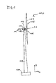
- FIG. 1 shows a wind turbine 100.
- the wind turbine has a foundation 101, by means of the wind turbine is mounted on a surface.
- a pedestal device 102 is coupled to the foundation.
- the standing device 102 is in the Z direction of FIG. 1 elongated.
- the standing device 102 is in particular a tower, for example designed as a steel tube, prestressed concrete, truss or sandwich tower.
- the nacelle comprises a generator 104 which is coupled to a rotor 109 via a rotor shaft 105.
- the rotor shaft 105 is coupled to a rotor hub 106 of the rotor 109.
- the rotor 109 further has a rotor blade 107 or a plurality of rotor blades 107, which are coupled to the rotor hub 106.
- the rotor 109 is set in operation by wind in rotation and this rotation transmitted via the rotor shaft 105 to the generator 104, which converts the kinetic energy of the rotor 109 into electrical energy.
- the nacelle 103 is coupled to the jig 102 so that the nacelle with the rotor is rotatable about the longitudinal axis of the jig 102.
- the machine house 103 is rotatably mounted on the stand device 102 via an azimuth rotary connection such that the machine house 103 and thus also the rotor shaft 105 and in particular the longitudinal axis of the rotor shaft 105 can be tracked in its horizontal orientation of the wind direction.
- the machine house 103 is aligned so that the rotor shaft 105 is aligned in the direction of the measured wind direction.
- a control device 113 is arranged, which is arranged to effect, depending on the measured wind direction 127, an alignment of the rotor.
- the control device 113 is, in embodiments, part of an arrangement 112 comprising the control device 113 and the wind energy plant 100.
- the wind direction 127 is measured, averaged and determined over a time interval of 10 minutes, for example, as the rotor hub 106 is to be tracked in the wind direction.
- the time interval is longer than 10 minutes, in yet further embodiments shorter than 10 minutes.
- the wind energy plant is aligned so that an oblique gas flow is avoided or minimized as possible.
- the wind turbine has for this purpose a device for determining the wind direction, e.g. a sensor for determining the wind direction by means of a wind vane or a 2D ultrasonic anemometer for determining the horizontal components of the wind speed and the wind direction.
- the device for determining the wind direction acquires at least measured values of the wind direction 127 and transmits these to the control device 113.
- control device 113 outputs a control signal to the azimuth drive device (not shown).
- the signal can, for example, directly be passed to a frequency converter, via which an azimuth drive is fed.
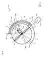
- FIG. 2 shows a system 110 of a wind turbine 100 and a radar system 111 according to an embodiment.
- the wind turbine 100 is shown in plan view.
- the radar system 111 is a weather radar system that is configured to detect precipitation, the intensity and movement of weather systems, or an air traffic control radar system for monitoring air traffic.
- the wind turbine 100 is arranged in the system 110 in an effective range of the radar system 111.
- the electromagnetic waves which are emitted by a transmitting and receiving antenna of the radar system, reach the wind energy plant 100.
- the movement of the rotor 109 and in particular of the rotor blades 107 is detected by the radar system 111.
- the rotational motion of the rotor blades has a pattern that is detected by the radar system as a weather phenomenon, such as precipitation.
- a position 125 of the radar system with respect to the wind energy plant 110 is determined.
- a straight line 126 is determined on which the radar system 111 and the rotor hub 106 lie.
- the effective range of the radar system 111 is in the region of the straight line 126.
- the effective range of the radar system surrounds the straight line 126.
- areas 121, 122 and 123, 124 (FIG. FIG. 3 ), in which an alignment of the rotor in response to the determined wind direction 127, an orientation of the axis of rotation of the rotor, in particular an orientation of the rotor shaft 105, should not be taken permanently.
- the regions 121, 122 and 123, 124 are determined in particular as a function of the straight line 126.
- less than 4 regions are determined which are avoided in the alignment of the rotor shaft 105 as a function of the determined wind direction 127, for example 2 regions.
- more than 4 regions are determined which are avoided in the alignment of the rotor shaft 105 as a function of the determined wind direction 127, for example 6 regions. This is the case in particular when the wind power plant is arranged in the effective range of two or more radar systems.
- further areas are determined by measurement, within which operation of the wind turbine proves to be disturbing the radar system.
- the area 122 is determined as a function of an angle A between the rotor shaft and the straight line 126.
- the angle A is 90 ° for the region 122.
- the size of the area about the longitudinal direction of the rotor shaft is predetermined by a further angle C.
- the angle C is the opening angle of the areas which, when the rotor shaft 105 is aligned with the longitudinal axis of the standing device 102 should not be taken permanently.
- the opening angle of the regions is in each case the same size in embodiments. In further embodiments, the opening angle of the regions is different in each case.
- the angle C specifies the width of the region 122.
- the angle C is dependent on the radar system 111 and the structural design of the wind turbine 100, in particular of the constructive shape of the rotor blades 107.
- the angle C is set so that the range 122 is so large that a significant disturbance of the radar over a longer period is avoided.
- the areas 121 and 123 and 124 are determined, the angle A has for this purpose a value of 180 ° (range 121), 270 ° (range 123) and 0 ° (range 124).
- an absolute geographic coordinate 128 is given, such as the north direction.
- the absolute geographic coordinate 128 is determined, for example, when setting up the wind turbine and stored in the control device 113.
- the regions 121, 122, 123, and 124 are determined in the embodiments as a function of the absolute geographic coordinate 128.
- An angle B between the absolute geographic coordinate 128 and the straight line 126 is determined.
- the area 122 results from the angle B - 90 °, so that an angle D is formed between the longitudinal direction of the shaft 105 and the direction of the absolute geographic coordinate 128.
- the region 121 results from the angle B + 90 °, so that an angle E is formed between the absolute geographic coordinate 128 and the middle of the region 121.
- the middle of area 124 concludes with the absolute geographical Coordinate 128 the angle B.
- the middle of the area 123 results from the angle B + 180 °.
- the areas 121 and 122 are thus determined so that the rotor hub 105 is not aligned for a long period of time so that the longitudinal direction of the rotor blades 107 is directed in the direction of the straight line 126.
- the areas are determined so that the straight line 126 is not aligned over a longer period of time in the plane of rotation of the rotor blades.
- the regions 121 and 122 indicate an orientation to be avoided for the rotor shaft 105, in which the longitudinal direction of the rotor blades 107 is in the direction of the straight line 126.
- FIG. 3 shows a rotated plan view of the system 110 of FIG. 2 .
- the regions 123 and 124 each define an alignment region of the rotor shaft 105 in which the longitudinal direction of the rotor blades 107 is transverse to the straight line 126.
- An alignment of the rotor shaft 105 in the areas 123 and 124 is avoided, so that an alignment of the rotor 109 is avoided, in which the longitudinal direction of the rotor blades 107 is transverse to the straight line 126.
- an optimal orientation of the wind turbine is determined as a function of the wind direction 127, in which the rotor shaft 105 in one of the areas 121, 122, 123 or 124 is aligned, the control device 113, the rotor shaft 105 to an edge of the corresponding area, for example, to an edge 129 of the region 122 from.
- the wind turbine is as close as possible to the optimal alignment and therefore still operable effectively.
- the radar system 111 is little influenced by the wind turbine.
- the wind turbine in particular the control device 113, is set up to provide information to the radar system 111 when, during alignment of the rotor shaft 105, one of the regions to be avoided 121, 122, 123 or 124 is traversed.
- the radar system can then take into account the disturbance by the wind turbine during this time. For example, during the time that the rotor hub 105 is in one of the regions to be avoided, the radar system 111 does not evaluate the radar signals.
- the opening angle C of the area 122 is 16 °, that is from -8 to + 8 °, and the wind turbine is operated so that it is aligned in the direction of + 9 ° with respect to the center of the area 122 and is over a time interval of 10 minutes determines that the wind direction has set on average to -9 ° with respect to the center of the area 122, it is permissible to track the rotor hub 105 through the area to be avoided 122. For example, it is found that the wind direction averages -2 ° with respect to the center of the area 122 has set, the plant in its orientation to - 8 °, so the nearest edge 129 of the area 122, be tracked. In this way, an oblique flow is minimized taking into account an area to be avoided.
Abstract
Description
Die Erfindung betrifft ein Verfahren zum Betreiben einer Windenergieanlage sowie eine Anordnung mit einer solchen Windenergieanlage, die eingerichtet ist das Verfahren auszuführen. Die Erfindung betrifft weiterhin ein System mit einer solchen Anordnung und einem Radarsystem, insbesondere einem Wetterradarsystem oder einem Flugsicherungsradarsystem.The invention relates to a method for operating a wind turbine and an arrangement with such a wind turbine, which is configured to carry out the method. The invention further relates to a system with such an arrangement and a radar system, in particular a weather radar system or an air traffic control radar system.
Wetterradarsysteme werden verwendet, um Niederschlag, Intensität und die Bewegung von Niederschlagssystemen zu detektieren, die Art des Niederschlags zu bestimmen (beispielsweise Regen, Schnee, Hagel), sowie Vorhersagen über die zeitliche und räumliche Entwicklung von Niederschlagssystemen zu treffen. Flugsicherungsradarsysteme werden zur Überwachung des Flugverkehrs eingesetzt.Weather radar systems are used to detect precipitation, intensity and movement of precipitation systems, to determine the type of precipitation (for example rain, snow, hail), as well as to predict the temporal and spatial evolution of precipitation systems. Air traffic control radar systems are used to monitor air traffic.
Radarsysteme emittieren gerichtete Primärsignale gepulster elektromagnetischer Strahlung im S-Band bzw. L-Band des Mikrowellenbereiches. Die Primärsignale werden mittels eines Impuls-Magnetrons oder einer Klystron-Röhre erzeugt, die über einen Wellenleiter mit einer Parabolantenne verbunden ist, die sowohl als Sende- als auch als Empfangsvorrichtung vorgesehen ist. Die elektromagnetischen Pulse breiten sich gerichtet von der Radarstation radial in einem Raumwinkel θ aus und werden an sich in diesem Raumwinkel befindenden Objekten wie Niederschlagssystemen, Geländeerhebungen, Flugzeugen, oder anderen anthropogenen Objekten reflektiert. Zwischen den einzelnen Pulsen dient die Radarstation als Empfänger für reflektierte Sekundärsignale. Der horizontale Abstand eines reflektierenden Objekts kann aus der Laufzeit der reflektierten, sich mit Lichtgeschwindigkeit im Pulsvolumen ausbreitenden elektromagnetischen Welle bestimmt werden. Aus der Phasenverschiebung der zurück gestreuten Sekundärsignale
aufeinander folgender Pulse kann zudem die Geschwindigkeit von reflektierenden Objekten abgeleitet werden ((Puls)-Doppler-Radar). Die radiale Doppler-Geschwindigkeit des Streuers ergibt sich dabei aus der Korrelation der Intensitäten aufeinander folgend detektierter Sekundärpulse. Die Tangentialgeschwindigkeit des Streuers bezüglich der Radarstation lässt sich aus der radialen Projektion der Tangentialgeschwindigkeit aus in benachbarten Winkelbereichen erfassten Streusignalen ableiten.Radar systems emit directional primary signals of pulsed electromagnetic radiation in the S-band or L-band of the microwave range. The primary signals are generated by means of a pulse magnetron or a klystron tube, which is connected via a waveguide to a parabolic antenna, which is provided both as a transmitting and as a receiving device. The electromagnetic pulses radiate out from the radar station radially at a solid angle θ and become in themselves at that solid angle Reflected objects such as rainfall systems, terrain surveys, aircraft, or other anthropogenic objects. Between the individual pulses, the radar station serves as a receiver for reflected secondary signals. The horizontal distance of a reflecting object can be determined from the transit time of the reflected electromagnetic wave propagating at the speed of light in the pulse volume. From the phase shift of the backscattered secondary signals
In addition, the speed of reflecting objects can be derived from (successive) pulses ((pulse) Doppler radar). The radial Doppler velocity of the scatterer results from the correlation of the intensities of successively detected secondary pulses. The tangential velocity of the spreader with respect to the radar station can be derived from the radial projection of the tangential velocity from scattered signals detected in adjacent angular ranges.
Windenergieanlagen können sich nachteilig auf die Auswertegenauigkeit von Radarsystemen auswirken. Durch die Rotationsbewegung der Rotorblätter und das sich windabhängig ändernde Profil erzeugen Windenergieanlagen Streusignale, die von Radarsystemen fehlinterpretiert werden können. Werden Windenergieanlagen gemäß einer Windrichtung ausgerichtet, welche um ungefähr 90° bezüglich der Einfallsrichtung eines Radar-Pulses gedreht liegt, können durch die Streuung an den sich bewegenden Rotorblättern Dubletten von
Geschwindigkeitssignaturen entstehen, die natürlichen Wettergegebenheiten ähneln und in kritischen
Wettersituationen zu Fehlinterpretationen und ungenauen kurzfristigen Wettervorhersagen führen können. Ebenso wirken sich derartige Störsignale nachteilig auf die Erkennung von Flugzeugen und die Bestimmung ihrer Flugbahnen aus. Ferner werden bezüglich der Einfallsrichtung leewärts befindliche Wettersysteme durch Windenergieanlagen verdeckt, was zu einer Abschwächung der Intensität der Sekundärsignale solcher Wettersysteme führt und diese bezüglich ihrer Niederschlagsintensität schlechter bewertbar macht.Wind turbines can have a detrimental effect on the evaluation accuracy of radar systems. Due to the rotational movement of the rotor blades and the wind-dependent changing profile wind turbines generate stray signals that can be misinterpreted by radar systems. If wind turbines are aligned according to a wind direction, which is rotated by approximately 90 ° with respect to the direction of incidence of a radar pulse, the scattering of the moving rotor blades can cause doublets of
Speed signatures emerge that resemble natural weather conditions and critical ones
Weather conditions can lead to misinterpretations and inaccurate short-term weather forecasts. Likewise, such spurious signals adversely affect the detection of Aircraft and the determination of their trajectories. Furthermore, weather systems located leeward with respect to the direction of incidence are obscured by wind turbines, which leads to a weakening of the intensity of the secondary signals of such weather systems and makes them worse valued in terms of their precipitation intensity.
Die
Die
Es ist wünschenswert, ein Verfahren zum Betreiben einer Windenergieanlage anzugeben, mit dem die Windenergieanlage effektiv betreibbar ist und gleichzeitig das Radarsystem wenig beeinflusst. Es ist weiterhin wünschenswert, eine Anordnung mit einer solchen Windenergieanlage anzugeben, die eingerichtet ist das Verfahren auszuführen. Weiterhin ist es wünschenswert, ein System anzugeben, das eine solche Anordnung und ein Radarsystem umfasst, so dass die Anordnung das Radarsystem wenig beeinflusst.It is desirable to provide a method for operating a wind turbine, with which the wind turbine can be operated effectively and at the same time has little effect on the radar system. It is further desirable to provide an arrangement with such a wind turbine, which is set up to carry out the method. Furthermore, it is desirable to specify a system comprising such an arrangement and a radar system so that the arrangement has little effect on the radar system.
In einer Ausführungsform der Erfindung umfasst ein Verfahren zum Betreiben einer Windenergieanlage ein Bereitstellen einer Windenergieanlage. Die Windenergieanlage weist eine länglich ausgedehnte Standvorrichtung, insbesondere einen Turm, beispielsweise ausgeführt als Stahlrohr-, Spannbeton-, Fachwerk- oder Sandwichturm, sowie einen drehbar auf der Standvorrichtung gelagerten Generator auf. Der Generator ist über eine Rotornabe mit einem Rotor und einer Rotornabe gekoppelt. Der Rotor weist wenigstens ein länglich ausgedehntes Rotorblatt auf. Eine Position eines Radarsystems in Bezug auf die Windenergieanlage wird ermittelt. Ein Bereich für die Rotationsachse des Rotors in Richtung des Generators wird in Abhängigkeit von der ermittelten Position ermittelt, der bei einer Ausrichtung der Rotorwelle um die Längsachse der Standvorrichtung nicht dauerhaft eingenommen werden soll.In one embodiment of the invention, a method of operating a wind turbine includes providing a wind turbine. The wind turbine has a longitudinally extended stand device, in particular a tower, for example designed as a steel tube, prestressed concrete, truss or sandwich tower, as well as a rotatably mounted on the stand device generator. The generator is coupled via a rotor hub with a rotor and a rotor hub. The rotor has at least one elongated rotor blade. A position of a radar system with respect to the wind turbine is determined. An area for the axis of rotation of the rotor in the direction of the generator is determined as a function of the determined position, which is not to be permanently assumed when the rotor shaft is aligned about the longitudinal axis of the stationary device.
Wenn die Rotationsachse des Rotors um die Längsachse der Standvorrichtung gedreht wird, insbesondere um den Rotor in Abhängigkeit von einer gemessenen Windrichtung möglichst optimal auszurichten, wird der Bereich vermieden, in dem die Bewegung des Rotors das Radarsystem stark beeinflusst. Wenn die Rotationsachse des Rotors um die Längsachse der Standvorrichtung gedreht wird, insbesondere um den Rotor in Abhängigkeit von einer gemessenen Windrichtung möglichst optimal auszurichten, soll der Bereich nicht dauerhaft eingenommen werden, in dem die Bewegung des Rotors das Radarsystem stark beeinflusst. Der Bereich, der vermieden wird, entspricht dem Bereich, der nicht dauerhaft eingenommen werden soll. Der Bereich, der nicht dauerhaft eingenommen werden soll, darf bei einer Ausrichtung der Rotationsachse des Rotors in Abhängigkeit von einer Windrichtung durchfahren werden. Ein Zeitraum ist vorgegeben, für den die Rotationsachse des Rotors in dem Bereich ausgerichtet sein darf. Eine Position innerhalb des Bereiches länger als der vorgegebene Zeitraum wird nicht eingenommen. Der Zeitraum ist beispielsweise in Abhängigkeit von einer Geschwindigkeit vorgegeben, mit der die Rotationsachse des Rotors ausrichtbar ist. Die Rotationsachse des Rotors entspricht insbesondere der Längsachse einer Rotorwelle.If the axis of rotation of the rotor is rotated about the longitudinal axis of the stand device, in particular in order to optimally align the rotor depending on a measured wind direction, the area is avoided in which the movement of the rotor greatly influences the radar system. If the axis of rotation of the rotor is rotated about the longitudinal axis of the stand device, in particular in order to optimally align the rotor depending on a measured wind direction, the area should not be taken permanently, in which the movement of the rotor greatly influences the radar system. The area that is avoided corresponds to the area that should not be permanently occupied. The area which is not to be permanently occupied may be passed through with an orientation of the axis of rotation of the rotor depending on a wind direction. A period is given for which the Rotation axis of the rotor may be aligned in the area. A position within the range longer than the predetermined period is not taken. The period is predetermined, for example, as a function of a speed with which the axis of rotation of the rotor can be aligned. The axis of rotation of the rotor corresponds in particular to the longitudinal axis of a rotor shaft.
Das Radarsystem ist insbesondere ein Wetterradarsystem zur Detektion von Wettersystemen oder ein Radarsystem zur Flugsicherung. Insbesondere werden mindestens zwei Bereiche vermieden, in denen die Bewegung des Rotors bei dem Radarsystem Wahrnehmungen, die Wetterphänomenen ähnlich sind, auslöst. Dadurch ist die Windenergieanlage im Wirkbereich von einem oder mehreren Radarsystemen bei gleichzeitigem zuverlässigem Betrieb des Radarsystems betreibbar.The radar system is in particular a weather radar system for the detection of weather systems or a radar system for air traffic control. In particular, at least two areas are avoided in which the movement of the rotor in the radar system triggers perceptions that are similar to weather phenomena. As a result, the wind power plant can be operated in the effective range of one or more radar systems with simultaneous reliable operation of the radar system.
In Ausführungsformen wird der Bereich, der bei der Ausrichtung der Rotationsachse des Rotors nicht dauerhaft eingenommen werden soll, in Abhängigkeit von einer Geraden ermittelt, auf der das Radarsystem und die Rotornabe liegen. Die Gerade ist eine gedachte direkte Verbindungslinie zwischen dem Radarsystem und der Rotornabe. Der Wirkbereich des Radarsystems ist insbesondere ein Bereich um diese Gerade.In embodiments, the area which is not to be permanently occupied in the alignment of the axis of rotation of the rotor is determined in dependence on a straight line on which the radar system and the rotor hub lie. The straight line is an imaginary direct connecting line between the radar system and the rotor hub. The effective range of the radar system is in particular an area around this straight line.
In Ausführungsformen wird eine absolute geografische Koordinate vorgegeben, beispielsweise die Nordrichtung am Standort der Windenergieanlage. In Abhängigkeit von der absoluten geografischen Koordinate wird der Bereich ermittelt, der bei der Ausrichtung nicht dauerhaft eingenommen werden soll.In embodiments, an absolute geographic coordinate is specified, for example, the north direction at the location of the wind turbine. Depending on the absolute geographical co-ordinate, the area is determined which should not be permanently taken during the alignment.
Wird eine Windrichtung ermittelt, bei der eine optimale Ausrichtung in dem zu vermeidenden Bereich liegt, wird in Ausführungsformen die Rotationsachse des Rotors an den Rand des zu vermeidenden Bereiches ausgerichtet. Herkömmlich soll ein Betrieb bei Schräganströmung, bei dem die Rotorwelle nicht möglichst optimal in Windrichtung ausgerichtet wird, weitestgehend vermieden werden, da während eines solchen Betriebs bei Schräganströmung die mechanische Belastung auf die Windenergieanlage, insbesondere auf Lager und Getriebe, höher ist als bei einer möglichst optimalen Ausrichtung in Windrichtung.If a wind direction is determined in which an optimal orientation lies in the region to be avoided, in embodiments the rotational axis of the rotor is aligned with the edge of the region to be avoided. Conventionally, an operation with oblique flow, in which the rotor shaft is not optimally aligned in the wind direction, should be largely avoided, since during such operation in oblique flow, the mechanical load on the wind turbine, especially on bearings and gearbox, is higher than optimal Orientation in the wind direction.
Wird in Ausführungsformen die Rotationsachse des Rotors an den Rand des zu vermeidenden Bereiches ausgerichtet, wird die Windenergieanlage bei Schräganströmung betrieben. Um die Windenergieanlage möglichst effektiv zu betreiben, wird die Rotationsachse des Rotors an den Rand des Bereiches ausgerichtet, an dem die Schräganströmung minimal ist, insbesondere im Vergleich zu dem anderen Rand des Bereiches. So ist ein möglichst effektiver Betrieb der Windenergieanlage bei gleichzeitig geringer Beeinflussung des Radarsystems möglich. Insbesondere ist ein Durchfahren der zu vermeidenden Bereiche während der Ausrichtung möglich, ein länger andauernder Betrieb innerhalb der zu vermeidenden Bereiche wird jedoch vermieden.If, in embodiments, the axis of rotation of the rotor is aligned with the edge of the region to be avoided, the wind energy plant is operated in oblique flow. In order to operate the wind turbine as effectively as possible, the axis of rotation of the rotor is aligned with the edge of the region at which the oblique flow is minimal, in particular compared to the other edge of the range. Thus, the most effective possible operation of the wind turbine with simultaneous low influence of the radar system is possible. In particular, a passage through the areas to be avoided during the alignment is possible, a longer-lasting operation within the areas to be avoided, however, is avoided.
In Ausführungsformen wird ein Wert für eine tatsächliche Drehzahl des Rotors ermittelt, insbesondere unmittelbar bevor der zu vermeidende Bereich durchfahren wird. Ein zweiter Wert für die Drehzahl des Rotors wird vorgegeben. Der zweite Wert für die Drehzahl ist insbesondere abhängig von dem Radarsystem und ist so gewählt, dass die Drehung des Rotors bei einer Drehzahl von kleiner oder gleich dem zweiten Wert das Radarsystem nicht oder nur unwesentlich beeinträchtigt. Insbesondere entspricht der zweite Wert einem Leerlaufbetrieb der Windenergieanlage, so dass sich der Rotor beim Durchfahren des Bereiches, der nicht dauerhaft eingenommen werden soll, nur mit einer geringen Drehzahl dreht. Die Drehzahl des Rotors wird auf den vorgegebenen zweiten Wert, beispielsweise unter Verwendung eines Rotorblattverstellsystems eingeregelt. Anschließend wird der zu vermeidende Bereich durchfahren. Hat die Längsachse der Rotorwelle den zu vermeidende Bereich durchfahren, kann die Drehzahl des Rotors entsprechend der Windgeschwindigkeit eingeregelt und die Drehzahl erhöht werden. Eine Beeinflussung des Radarsystems durch das Durchfahren eines zu vermeidenden Bereiches wird somit zusätzlich vermieden.In embodiments, a value for an actual speed of the rotor is determined, in particular immediately before the area to be avoided is traversed. A second value for the speed of the rotor is specified. The second value for the speed is particularly dependent on the radar system and is chosen so that the rotation of the rotor at a speed of less than or equal to the second value the radar system not or only slightly affected. In particular, the second value corresponds to an idling operation of the wind power plant, so that the rotor rotates only at a low speed when passing through the area which is not intended to be permanently occupied. The speed of the rotor is adjusted to the predetermined second value, for example using a rotor blade pitch system. Subsequently, the area to be avoided is passed through. If the longitudinal axis of the rotor shaft has passed through the area to be avoided, the rotational speed of the rotor can be adjusted in accordance with the wind speed and the rotational speed can be increased. An influence of the radar system by driving through an area to be avoided is thus additionally avoided.
Insbesondere wird der Bereich vermieden, in dem die Längsachse des Rotorblatts in Richtung der Verbindungslinie zwischen dem Radarsystem und der Rotornabe ist, also die Rotorwelle quer, insbesondere rechtwinklig, zu der Verbindungslinie ausgerichtet ist.In particular, the region is avoided in which the longitudinal axis of the rotor blade in the direction of the connecting line between the radar system and the rotor hub, ie the rotor shaft is aligned transversely, in particular at right angles, to the connecting line.
In weiteren Ausführungsformen werden die Bereiche vermieden, in denen die Längsrichtung des Rotorblattes quer zu der Verbindungslinie ausgerichtet ist, also die Rotorwelle in Richtung der Verbindungslinie ausgerichtet ist. Insbesondere werden die Bereiche vermieden, in denen die Längsrichtung des Rotorblattes rechtwinklig zu der Verbindungslinie ausgerichtet ist.So werden die Bereiche vermieden, in denen die Bewegung des Rotors das Radarsystem stark beeinflusst.In further embodiments, the regions are avoided in which the longitudinal direction of the rotor blade is aligned transversely to the connecting line, so the rotor shaft is aligned in the direction of the connecting line. In particular, the areas are avoided in which the longitudinal direction of the rotor blade is oriented at right angles to the connecting line. Thus, the areas are avoided in which the movement of the rotor greatly influences the radar system.
In weiteren Ausführungsformen wird eine Information für das Radarsystem bereitgestellt, wenn die Rotationsachse des Rotors in dem Bereich ist, der bei der Ausrichtung der Rotorwelle um die Längsache der Standvorrichtung nicht dauerhaft eingenommen werden soll. Die Information wird in Ausführungsformen durch eine Steuervorrichtung der Windenergieanlage bereitgestellt. In weiteren Ausführungsformen wird die Information durch ein zentrales System bereitgestellt. Das zentrale System ist beispielsweise ein Steuersystem eines Windenergieanlagenparks, das die Informationen der jeweiligen Windenergieanlagen des Parks sammelt und bereitstellt.In further embodiments, information is provided to the radar system when the axis of rotation of the rotor is in the region that is in alignment with the Rotor shaft should not be taken permanently around the longitudinal axis of the stand device. The information is provided in embodiments by a controller of the wind turbine. In further embodiments, the information is provided by a central system. The central system is for example a control system of a wind turbine park, which collects and provides the information of the respective wind turbines of the park.
In weiteren Ausführungsformen ist die Windenergieanlage eingerichtet, festzustellen, ob das Radarsystem aktiv ist. Lediglich dann, wenn das Radarsystem aktiv ist, werden die Bereiche, die nicht eingenommen werden sollen, auch tatsächlich nicht dauerhaft eingenommen. Die Information des Radarsystems wird in Ausführungsformen durch das Radarsystem einer Steuervorrichtung der Windenergieanlage bereitgestellt. In weiteren Ausführungsformen wird die Information durch das Radarsystem einem zentralen System bereitgestellt. Das zentrale System ist beispielsweise ein Steuersystem eines Windenergieanlagenparks, das die Information einer Vielzahl von Windenergieanlagen eines Windenergieanlagenparks bereitstellt.In other embodiments, the wind turbine is configured to determine if the radar system is active. Only then, when the radar system is active, the areas that should not be taken, actually not permanently taken. The information of the radar system is provided in embodiments by the radar system of a control device of the wind turbine. In further embodiments, the information is provided by the radar system to a central system. The central system is, for example, a control system of a wind energy plant park, which provides the information of a plurality of wind turbines of a wind turbine park.
In einer Ausführungsform umfasst eine Anordnung eine Windenergieanlage. Weiterhin umfasst die Anordnung die Steuervorrichtung, die eingerichtet ist, Verfahrenschritte zum Betreiben der Windenergieanlage gemäß den Ausführungsformen auszuführen.In one embodiment, an arrangement includes a wind turbine. Furthermore, the arrangement comprises the control device, which is set up to carry out method steps for operating the wind energy plant according to the embodiments.
In einer Ausführungsform umfasst ein System eine solche Anordnung. Weiterhin umfasst das System ein Radarsystem, wobei die Windenergieanlage in einem Wirkbereich des Radarsystems angeordnet ist. Das Radarsystem ist insbesondere ein Wetterradarsystem oder ein Radarsystem zur Flugsicherung.In one embodiment, a system includes such an arrangement. Furthermore, the system comprises a radar system, wherein the wind turbine in an effective range of the Radar system is arranged. The radar system is in particular a weather radar system or a radar system for air traffic control.
Weitere Vorteile, Merkmale und Weiterbildungen ergeben sich aus den nachfolgenden in Verbindung mit den Figuren erläuterten Beispielen. Gleiche, gleichartige und gleichwirkende Elemente können in den Figuren mit den gleichen Bezugszeichen versehen sein. Die dargestellten Elemente und deren Größenverhältnisse zueinander sind grundsätzlich nicht als maßstabsgerecht anzusehen, vielmehr können einzelne Elemente, wie beispielsweise Bereiche, zum besseren Verständnis übertrieben dick oder groß dimensioniert dargestellt sein.Further advantages, features and developments emerge from the following examples explained in conjunction with the figures. The same, similar and equivalent elements may be provided in the figures with the same reference numerals. The illustrated elements and their proportions to each other are basically not to be regarded as true to scale, but individual elements, such as areas, for exaggerated exaggeration be shown thick or large.
Es zeigen:
-
Figur 1 eine schematische Darstellung einer Windenergieanlage gemäß einer Ausführungsform, und -
Figur 2 eine schematische Darstellung einer Aufsicht auf die Windenergieanlage derFigur 1 und ein Radarsystem gemäß einer Ausführungsform, -
Figur 3 eine schematische Darstellung einer Aufsicht auf die Windenergieanlage derFigur 1 und ein Radarsystem gemäß einer weiteren Ausführungsform.
-
FIG. 1 a schematic representation of a wind turbine according to an embodiment, and -
FIG. 2 a schematic representation of a plan view of the wind turbine ofFIG. 1 and a radar system according to an embodiment, -
FIG. 3 a schematic representation of a plan view of the wind turbine ofFIG. 1 and a radar system according to another embodiment.
An einem dem Fundament 101 gegenüberliegenden Ende 108 der Standvorrichtung 102 ist ein Maschinenhaus 103 angeordnet. Das Maschinenhaus umfasst einen Generator 104, der über eine Rotorwelle 105 mit einem Rotor 109 gekoppelt ist. Insbesondere ist die Rotorwelle 105 mit einer Rotornabe 106 des Rotors 109 gekoppelt. Der Rotor 109 weist weiterhin ein Rotorblatt 107 beziehungsweise eine Mehrzahl von Rotorblättern 107 auf, die mit der Rotornabe 106 gekoppelt sind. Der Rotor 109 wird in Betrieb durch Wind in Rotation versetzt und diese Rotation über die Rotorwelle 105 zu dem Generator 104 übertragen, der die kinetische Energie des Rotors 109 in elektrische Energie umwandelt.On a
Das Maschinenhaus 103 ist mit der Standvorrichtung 102 so gekoppelt, dass das Maschinenhaus mit dem Rotor um die Längsachse der Standvorrichtung 102 drehbar ist. Das Maschinenhaus 103 ist über eine Azimutdrehverbindung derart drehbar auf der Standvorrichtung 102 gelagert, dass das Maschinenhaus 103 und damit auch die Rotorwelle 105 und insbesondere die Längsachse der Rotorwelle 105 in ihrer horizontalen Ausrichtung der Windrichtung nachgeführt werden kann. Dadurch ist es möglich, das Maschinenhaus 103 und insbesondere den Rotor 109 in Abhängigkeit von einer gemessenen Windrichtung 127 so ausrichten, dass eine hohe Effizienz bei der Umwandlung der kinetischen Energie des Windes in elektrische Energie mittels des Generators 104 erreicht wird. Insbesondere wird das Maschinenhaus 103 so ausgerichtet, dass die Rotorwelle 105 in Richtung der gemessenen Windrichtung ausgerichtet ist.The
Zur Ausrichtung des Rotors ist eine Steuervorrichtung 113 angeordnet, die eingerichtet ist, in Abhängigkeit von der gemessenen Windrichtung 127 eine Ausrichtung des Rotors zu erwirken. Die Steuervorrichtung 113 ist in Ausführungsformen Teil einer Anordnung 112, die die Steuervorrichtung 113 und die Windenergieanlage 100 aufweist.For the alignment of the rotor, a
Im Normalbetrieb der Windenergieanlage wird beispielsweise über ein Zeitintervall von 10 Minuten die Windrichtung 127 gemessen, gemittelt und bestimmt, wie die Rotornabe 106 der Windrichtung nachzuführen ist. Das Zeitintervall ist in weiteren Ausführungsformen länger als 10 Minuten, in wiederum weiteren Ausführungsformen kürzer als 10 Minuten. Im Normalbetrieb wird die Windenergieanlage so ausgerichtet, dass eine Schräganströmung vermieden oder möglichst minimal wird.During normal operation of the wind energy installation, the
Die Windenergieanlage weist dazu eine Vorrichtung zur Bestimmung der Windrichtung, z.B. einen Messwertgeber zur Windrichtungsbestimmung mittels einer Windfahne oder einem 2D-Ultraschallanemometer zur Bestimmung der horizontalen Komponenten der Windgeschwindigkeit und der Windrichtung auf. Die Vorrichtung zur Bestimmung der Windrichtung erfasst wenigstens Messwerte der Windrichtung 127 und überträgt diese an die Steuervorrichtung 113.The wind turbine has for this purpose a device for determining the wind direction, e.g. a sensor for determining the wind direction by means of a wind vane or a 2D ultrasonic anemometer for determining the horizontal components of the wind speed and the wind direction. The device for determining the wind direction acquires at least measured values of the
Für die Nachführung gibt die Steuervorrichtung 113 ein Steuerungssignal an die Azimutantriebsvorrichtung (nicht gezeigt) weiter. Dabei kann das Signal beispielsweise direkt an einen Frequenzumrichter weitergegeben werden, über den ein Azimutantrieb gespeist wird.For tracking, the
Das Radarsystem 111 ist insbesondere ein Wetterradarsystem, das eingerichtet ist, Niederschlag, die Intensität und die Bewegung von Wettersystemen zu detektieren oder ein Flugsicherungsradarsysteme zur Überwachung des Flugverkehrs.In particular, the
Die Windenergieanlage 100 ist in dem System 110 in einem Wirkbereich des Radarsystems 111 angeordnet. Die elektromagnetischen Wellen, die von einer Sende- und Empfangsantenne des Radarsystems ausgesendet werden, erreichen die Windenergieanlage 100. Die Bewegung des Rotors 109 und insbesondere der Rotorblätter 107 wird von dem Radarsystem 111 detektiert. Die Rotationsbewegung der Rotorblätter weist beispielsweise ein Muster auf, das von dem Radarsystem als ein Wetterphänomen, beispielsweise Niederschlag, erkannt wird.The
Zum Betreiben der Windenergieanlage 100 wird eine Position 125 des Radarsystems in Bezug auf die Windenergieanlage 110 ermittelt. Insbesondere wird dabei eine Gerade 126 ermittelt, auf der das Radarsystem 111 und die Rotornabe 106 liegen. Der Wirkbereich des Radarsystems 111 ist im Bereich der Geraden 126. Insbesondere umgibt der Wirkbereich des Radarsystems die Gerade 126.For operating the
Um die Windenergieanlage 100 so zu betreiben, dass das Radarsystem 111 möglichst wenig in seinem Betrieb beeinflusst wird, also die Bewegung des Rotors 109 möglichst wenig Störsignale bei dem Radarsystem 111 verursacht, werden in Abhängigkeit von der Position der Windenergieanlage 100 und des Radarsystems 111 relativ zueinander Bereiche 121, 122 und 123, 124 (
In weiteren Ausführungsformen werden weniger als 4 Bereiche ermittelt, die bei der Ausrichtung der Rotorwelle 105 in Abhängigkeit von der ermittelten Windrichtung 127 vermieden werden, beispielsweise 2 Bereiche. In weiteren Ausführungsformen werden mehr als 4 Bereiche ermittelt, die bei der Ausrichtung der Rotorwelle 105 in Abhängigkeit von der ermittelten Windrichtung 127 vermieden werden, beispielsweise 6 Bereiche. Dies ist insbesondere der Fall, wenn die Windenergieanlage im Wirkbereich von zwei oder mehr Radarsystemen angeordnet ist. Zudem werden in Ausführungsformen durch Messung weitere Bereiche ermittelt, innerhalb derer ein Betrieb der Windenergieanlage sich als störend auf das Radarsystem erweis.In further embodiments, less than 4 regions are determined which are avoided in the alignment of the
Beispielsweise wird der Bereich 122 in Abhängigkeit von einem Winkel A zwischen der Rotorwelle und der Geraden 126 ermittelt. Der Winkel A ist für den Bereich 122 90°. Die Größe des Bereiches um die Längsrichtung der Rotorwelle wird von einem weiteren Winkel C vorgegeben. Der Winkel C ist der Öffnungswinkel der Bereiche, die bei einer Ausrichtung der Rotorwelle 105 um die Längsache der Standvorrichtung 102 nicht dauerhaft eingenommen werden sollen. Der Öffnungswinkel der Bereiche ist in Ausführungsformen jeweils gleich groß. In weiteren Ausführungsformen ist der Öffnungswinkel der Bereiche jeweils verschieden. Der Winkel C gibt die Breite des Bereiches 122 vor. Insbesondere ist der Winkel C abhängig von dem Radarsystem 111 sowie von der konstruktiven Ausformung der Windenergieanlage 100, insbesondere von der konstruktiven Ausformung der Rotorblätter 107. Der Winkel C wird so vorgegeben, dass der Bereich 122 so groß ist, dass eine wesentliche Störung des Radarsystems über einen längeren Zeitraum vermieden wird. Vergleichbar dazu werden die Bereiche 121 und 123 sowie 124 ermittelt, der Winkel A hat hierfür einen Wert von 180° (Bereich 121), 270° (Bereich 123) beziehungsweise 0° (Bereich 124).For example, the
In weiteren Ausführungsformen ist eine absolute geografische Koordinate 128 vorgegeben, beispielsweise die Nordrichtung. Die absolute geografische Koordinate 128 wird beispielsweise beim Aufstellen der Windenergieanlage ermittelt und in der Steuervorrichtung 113 gespeichert.In other embodiments, an absolute geographic coordinate 128 is given, such as the north direction. The absolute geographic coordinate 128 is determined, for example, when setting up the wind turbine and stored in the
Die Bereiche 121, 122, 123 und 124 werden in den Ausführungsformen in Abhängigkeit von der absoluten geografischen Koordinate 128 ermittelt. Dabei wird ein Winkel B zwischen der absoluten geografischen Koordinate 128 und der Geraden 126 ermittelt. Der Bereich 122 ergibt sich aus dem Winkel B - 90°, so dass zwischen der Längsrichtung der Welle 105 und der Richtung der absoluten geografischen Koordinate 128 ein Winkel D ausgebildet wird. Entsprechend ergibt sich der Bereich 121 aus dem Winkel B + 90°, so dass zwischen der absoluten geografischen Koordinate 128 und der Mitte des Bereiches 121 ein Winkel E ausgebildet wird. Die Mitte des Bereiches 124 schließt mit der absoluten geografischen Koordinate 128 den Winkel B ein. Die Mitte des Bereiches 123 ergibt sich aus dem Winkel B + 180°.The
Die Bereiche 121 und 122 werden folglich so ermittelt, dass die Rotornabe 105 nicht über einen längeren Zeitraum so ausgerichtet wird, dass die Längsrichtung der Rotorblätter 107 in Richtung der Geraden 126 gerichtet ist. Die Bereiche werden so ermittelt, dass die Gerade 126 nicht über einen längeren Zeitraum in der Rotationsebene der Rotorblätter ausgerichtet ist. Die Bereiche 121 und 122 geben eine zu vermeidenden Ausrichtung für die Rotorwelle 105 vor, in der die Längsrichtung der Rotorblätter 107 in Richtung der Geraden 126 ist.The
Wird eine optimale Ausrichtung der Windenergieanlage in Abhängigkeit von der Windrichtung 127 ermittelt, in der die Rotorwelle 105 in einem der Bereiche 121, 122, 123 oder 124 ausgerichtet ist, richtet die Steuervorrichtung 113 die Rotorwelle 105 an einen Rand des entsprechenden Bereiches, beispielsweise an einen Rand 129 des Bereiches 122 aus. So ist die Windenergieanlage möglichst nah an der optimalen Ausrichtung und daher noch effektiv betreibbar. Gleichzeitig wird das Radarsystem 111 durch die Windenergieanlage wenig beeinflusst.If an optimal orientation of the wind turbine is determined as a function of the
In Ausführungsformen ist die Windenergieanlage, insbesondere die Steuervorrichtung 113, eingerichtet, eine Information für das Radarsystem 111 bereitzustellen, wenn beim Ausrichten der Rotorwelle 105 einer der zu vermeidenden Bereiche 121, 122, 123 oder 124 durchlaufen wird. Beim Ausrichten der Rotationsebene des Rotors 107 quer zu der Windrichtung 127 ist es möglich, dass sich die Rotorwelle 105 vorübergehend in einem der zu vermeidenden Bereiche 121, 122, 123 oder 124 befindet. In Abhängigkeit von der zur Verfügung gestellten Information kann dann das Radarsystem während dieser Zeit die Störung durch die Windenergieanlage berücksichtigen. Beispielsweise wertet das Radarsystem 111 in der Zeit, in der sich die Rotornabe 105 in einem der zu vermeidenden Bereiche befindet, die Radarsignale nicht aus.In embodiments, the wind turbine, in particular the
Ist beispielsweise der Öffnungswinkel C des Bereiches 122 16°, also von -8 bis +8°, und wird die Windenergieanlage so betrieben, dass sie in Richtung +9° in Bezug auf die Mitte des Bereiches 122 ausgerichtet ist und wird über ein Zeitintervall von 10 Minuten ermittelt, dass die Windrichtung sich im Mittel auf -9° in Bezug auf die Mitte des Bereiches 122 eingestellt hat, so ist es zulässig die Rotornabe 105 durch den zu vermeidenden Bereich 122 nachzuführen. Wird beispielsweise festgestellt, dass die Windrichtung sich im Mittel auf -2° in Bezug auf die Mitte des Bereiches 122 eingestellt hat, wird die Anlage in ihrer Ausrichtung auf - 8°, also dem nächstliegenden Rand 129 des Bereiches 122, nachgeführt werden. Auf diese Weise wird eine Schräganströmung unter Berücksichtigung eines zu vermeidenden Bereiches minimiert.For example, if the opening angle C of the
Durch die Vermeidung der Ausrichtung der Rotorwelle 105 zumindest in den Bereichen 121, 122, 123 und 124 wird ein Betrieb der Windenergieanlage 100 ermöglicht, der das Radarsystem 111 möglichst wenig beeinflusst. Dadurch, dass die Ausrichtungen des Rotors vermieden werden, in denen die Bewegung der Rotorblätter den Betrieb des Radarsystems 111 stark stört, ist ein zuverlässiger Betrieb des Radarsystems 111 und ein gleichzeitiger effektiver Betrieb der Windenergieanlage 100 möglich.By avoiding the orientation of the
Claims (15)
Rotationsachse des Rotors (109) um die Längsache der Standvorrichtung (102) nicht dauerhaft eingenommen werden soll.
Rotation axis of the rotor (109) to the longitudinal axis of the standing device (102) should not be taken permanently.
Priority Applications (4)
| Application Number | Priority Date | Filing Date | Title |
|---|---|---|---|
| PL11152546T PL2481918T3 (en) | 2011-01-28 | 2011-01-28 | Method for operating a wind farm in a RADAR neighbourhood |
| EP11152546.5A EP2481918B1 (en) | 2011-01-28 | 2011-01-28 | Method for operating a wind farm in a RADAR neighbourhood |
| US13/350,916 US9033660B2 (en) | 2011-01-28 | 2012-01-16 | Method for operating a wind turbine, arrangement and system |
| CN201210020275.2A CN102619689B (en) | 2011-01-28 | 2012-01-29 | Method for operating a wind turbine, arrangement and system |
Applications Claiming Priority (1)
| Application Number | Priority Date | Filing Date | Title |
|---|---|---|---|
| EP11152546.5A EP2481918B1 (en) | 2011-01-28 | 2011-01-28 | Method for operating a wind farm in a RADAR neighbourhood |
Publications (2)
| Publication Number | Publication Date |
|---|---|
| EP2481918A1 true EP2481918A1 (en) | 2012-08-01 |
| EP2481918B1 EP2481918B1 (en) | 2015-08-26 |
Family
ID=44170574
Family Applications (1)
| Application Number | Title | Priority Date | Filing Date |
|---|---|---|---|
| EP11152546.5A Active EP2481918B1 (en) | 2011-01-28 | 2011-01-28 | Method for operating a wind farm in a RADAR neighbourhood |
Country Status (4)
| Country | Link |
|---|---|
| US (1) | US9033660B2 (en) |
| EP (1) | EP2481918B1 (en) |
| CN (1) | CN102619689B (en) |
| PL (1) | PL2481918T3 (en) |
Cited By (2)
| Publication number | Priority date | Publication date | Assignee | Title |
|---|---|---|---|---|
| EP2725225A3 (en) * | 2012-10-24 | 2016-10-26 | Senvion GmbH | Wind turbine with reduced radar reflection |
| CN108387881A (en) * | 2018-02-01 | 2018-08-10 | 三峡大学 | A kind of accurate simulation algorithm of wind turbine blade echo |
Families Citing this family (2)
| Publication number | Priority date | Publication date | Assignee | Title |
|---|---|---|---|---|
| US10416300B2 (en) | 2016-09-01 | 2019-09-17 | Colorado State University Research Foundation | Suppressing cyclically time-varying radar signatures |
| DE102019114916A1 (en) * | 2019-06-04 | 2020-12-10 | WuF- Windenergie und Flugsicherheit GmbH | Method, arrangement and system for operating wind turbines in the vicinity of a radar system that monitors flight movements |
Citations (6)
| Publication number | Priority date | Publication date | Assignee | Title |
|---|---|---|---|---|
| US7302903B1 (en) * | 2004-07-23 | 2007-12-04 | Rudolph Behrens | Floating vessel for producing hydrocarbons and method for producing hydrocarbons |
| US20090202347A1 (en) * | 2008-02-08 | 2009-08-13 | Technology Service Corporation | Systems and methods for mitigating the effects of wind turbines on radar |
| WO2009144435A1 (en) * | 2008-05-29 | 2009-12-03 | Cambridge Consultants Limited | Radar system and method |
| WO2010099773A1 (en) | 2009-03-06 | 2010-09-10 | Eads Deutschland Gmbh | Method for detecting wind power plants using a radar system |
| WO2010109174A1 (en) | 2009-03-27 | 2010-09-30 | Qinetiq Limited | Electromagnetic field absorbing composition |
| WO2010122350A1 (en) | 2009-04-23 | 2010-10-28 | Vestas Wind Systems A/S | Incorporation of functional cloth into prepreg composites |
Family Cites Families (13)
| Publication number | Priority date | Publication date | Assignee | Title |
|---|---|---|---|---|
| US2484291A (en) * | 1945-07-13 | 1949-10-11 | Russell R Hays | Wind rotor |
| DK140382B (en) | 1977-07-25 | 1979-08-13 | Peder Ulrik Poulsen | Wind Power. |
| DE2737767C2 (en) * | 1977-08-22 | 1979-05-17 | Ulrich Prof. Dr.-Ing. 7312 Kirchheim Huetter | Wind turbine |
| US4449889A (en) * | 1983-01-20 | 1984-05-22 | Belden Ralph A | Windmill |
| DE10153403B4 (en) | 2001-11-01 | 2013-07-18 | Aloys Wobben | wind farm |
| EP1830447A1 (en) | 2006-03-02 | 2007-09-05 | ABB Research Ltd | Converter control unit using time-stamped voltage or current phasors |
| US7417332B2 (en) | 2006-08-24 | 2008-08-26 | General Electric Company | Method and apparatus of monitoring a machine |
| US7551130B2 (en) | 2007-11-21 | 2009-06-23 | General Electric Company | Wind turbine with data receiver |
| DE102008020154B4 (en) * | 2008-04-22 | 2011-04-28 | Repower Systems Ag | Method for operating a wind energy plant |
| DE102008024644B4 (en) | 2008-05-21 | 2018-07-26 | Airbus Defence and Space GmbH | Rotor blade with integrated radar absorber for a wind turbine |
| BRPI0920807A2 (en) | 2008-10-06 | 2015-12-22 | Flodesign Wind Turbine Corp | Wind turbine and method for reducing the radar signature of a wind turbine |
| GB0822468D0 (en) | 2008-12-10 | 2009-01-14 | Qinetiq Ltd | Method for mitigating the effects of clutter and interference on a radar system |
| WO2010098814A1 (en) * | 2009-02-28 | 2010-09-02 | Ener2 Llc | Improved wind energy device |
-
2011
- 2011-01-28 PL PL11152546T patent/PL2481918T3/en unknown
- 2011-01-28 EP EP11152546.5A patent/EP2481918B1/en active Active
-
2012
- 2012-01-16 US US13/350,916 patent/US9033660B2/en active Active
- 2012-01-29 CN CN201210020275.2A patent/CN102619689B/en not_active Expired - Fee Related
Patent Citations (6)
| Publication number | Priority date | Publication date | Assignee | Title |
|---|---|---|---|---|
| US7302903B1 (en) * | 2004-07-23 | 2007-12-04 | Rudolph Behrens | Floating vessel for producing hydrocarbons and method for producing hydrocarbons |
| US20090202347A1 (en) * | 2008-02-08 | 2009-08-13 | Technology Service Corporation | Systems and methods for mitigating the effects of wind turbines on radar |
| WO2009144435A1 (en) * | 2008-05-29 | 2009-12-03 | Cambridge Consultants Limited | Radar system and method |
| WO2010099773A1 (en) | 2009-03-06 | 2010-09-10 | Eads Deutschland Gmbh | Method for detecting wind power plants using a radar system |
| WO2010109174A1 (en) | 2009-03-27 | 2010-09-30 | Qinetiq Limited | Electromagnetic field absorbing composition |
| WO2010122350A1 (en) | 2009-04-23 | 2010-10-28 | Vestas Wind Systems A/S | Incorporation of functional cloth into prepreg composites |
Non-Patent Citations (2)
| Title |
|---|
| CIVIL AVIATION AUTHORITY: "CAA Policy and Guidelines on Wind Turbines", INTERNET CITATION, 1 July 2006 (2006-07-01), pages 1 - 66, XP007918986, ISBN: 978-0-11-792406-2, Retrieved from the Internet <URL:http://www.caa.co.uk/docs/33/Cap764.pdf> [retrieved on 20110704] * |
| DEPARTMENT OF TRADE AND INDUSTRY: "FEASIBILITY OF MITIGATING THE EFFECTS OF WINDFARMS ON PRIMARY RADAR", INTERNET CITATION, 1 January 2003 (2003-01-01), pages 1 - 71, XP007918988, Retrieved from the Internet <URL:http://www.bwea.com/aviation/ams_report.html> [retrieved on 20110704] * |
Cited By (2)
| Publication number | Priority date | Publication date | Assignee | Title |
|---|---|---|---|---|
| EP2725225A3 (en) * | 2012-10-24 | 2016-10-26 | Senvion GmbH | Wind turbine with reduced radar reflection |
| CN108387881A (en) * | 2018-02-01 | 2018-08-10 | 三峡大学 | A kind of accurate simulation algorithm of wind turbine blade echo |
Also Published As
| Publication number | Publication date |
|---|---|
| US9033660B2 (en) | 2015-05-19 |
| PL2481918T3 (en) | 2016-02-29 |
| CN102619689A (en) | 2012-08-01 |
| US20120195756A1 (en) | 2012-08-02 |
| CN102619689B (en) | 2014-10-22 |
| EP2481918B1 (en) | 2015-08-26 |
Similar Documents
| Publication | Publication Date | Title |
|---|---|---|
| DE602005003341T2 (en) | An apparatus and method for determining the speed and direction of the wind to which a wind turbine is exposed | |
| EP1432911B1 (en) | Early-warning system comprising sodar for wind energy turbines | |
| EP3390814B1 (en) | Method for determining an azimuth angle of a wind turbine | |
| EP2481918B1 (en) | Method for operating a wind farm in a RADAR neighbourhood | |
| EP3298272B1 (en) | Measuring assembly on a wind turbine | |
| EP2357359A2 (en) | Detection of the deformation of a blade of a wind turbine | |
| WO2002002936A1 (en) | Method for determining the angle of a rotor blade pertaining to a wind energy installation | |
| DE602004001726T2 (en) | Horizontal wave wind turbine and method of measuring the upward flow angle | |
| Norin | A quantitative analysis of the impact of wind turbines on operational Doppler weather radar data | |
| EP2366895B1 (en) | Method of determining the azimuth angle during maintenance of a wind turbine | |
| DE102012011357A1 (en) | Wind turbine control system and system for controlling a wind farm | |
| DE102008013392B4 (en) | Method for detecting the tracking of the rotor blades of a wind turbine | |
| EP3361094A1 (en) | Wind energy assembly and wind farm with at least one such wind turbine | |
| US11421651B2 (en) | Method of determining wind direction by means of a LiDAR sensor | |
| EP1750141B1 (en) | Device for simulating a movable radar target | |
| DE102018116941B4 (en) | Device and method for detecting the accumulation or the type of ice on a rotor blade of a rotor of a wind turbine | |
| EP2404190B1 (en) | Method for detecting wind power plants using a radar system | |
| DE102012024272A1 (en) | Method and device for reducing a rotor of a wind turbine loading nosemoment | |
| DE102009050235B3 (en) | Method for controlling a wind energy plant | |
| DE102012015456A1 (en) | Device for detecting deformation of rotor blade used in wind energy plant, has evaluation device to determine the deformation of rotor blade by using the electromagnetic signal and received signal when reflector is in rotor region | |
| EP2481919A1 (en) | Method for operating a wind farm, assembly and system | |
| EP3538758A1 (en) | Measuring system and method for detecting the accumulation of ice on the rotor blades of wind turbines | |
| EP3412908B1 (en) | Wind turbine comprising a system and method for mounting and for operating a wind turbine | |
| DE102015009704A1 (en) | Control and control method for a wind turbine | |
| DE102019112976A1 (en) | Method for determining a rotor alignment of a rotor in a wind turbine |
Legal Events
| Date | Code | Title | Description |
|---|---|---|---|
| PUAI | Public reference made under article 153(3) epc to a published international application that has entered the european phase |
Free format text: ORIGINAL CODE: 0009012 |
|
| AK | Designated contracting states |
Kind code of ref document: A1 Designated state(s): AL AT BE BG CH CY CZ DE DK EE ES FI FR GB GR HR HU IE IS IT LI LT LU LV MC MK MT NL NO PL PT RO RS SE SI SK SM TR |
|
| AX | Request for extension of the european patent |
Extension state: BA ME |
|
| 17P | Request for examination filed |
Effective date: 20130111 |
|
| RAP1 | Party data changed (applicant data changed or rights of an application transferred) |
Owner name: NORDEX ENERGY GMBH |
|
| 17Q | First examination report despatched |
Effective date: 20130816 |
|
| GRAP | Despatch of communication of intention to grant a patent |
Free format text: ORIGINAL CODE: EPIDOSNIGR1 |
|
| INTG | Intention to grant announced |
Effective date: 20150511 |
|
| GRAS | Grant fee paid |
Free format text: ORIGINAL CODE: EPIDOSNIGR3 |
|
| GRAA | (expected) grant |
Free format text: ORIGINAL CODE: 0009210 |
|
| AK | Designated contracting states |
Kind code of ref document: B1 Designated state(s): AL AT BE BG CH CY CZ DE DK EE ES FI FR GB GR HR HU IE IS IT LI LT LU LV MC MK MT NL NO PL PT RO RS SE SI SK SM TR |
|
| REG | Reference to a national code |
Ref country code: GB Ref legal event code: FG4D Free format text: NOT ENGLISH |
|
| REG | Reference to a national code |
Ref country code: CH Ref legal event code: EP |
|
| REG | Reference to a national code |
Ref country code: AT Ref legal event code: REF Ref document number: 745326 Country of ref document: AT Kind code of ref document: T Effective date: 20150915 |
|
| REG | Reference to a national code |
Ref country code: IE Ref legal event code: FG4D Free format text: LANGUAGE OF EP DOCUMENT: GERMAN |
|
| REG | Reference to a national code |
Ref country code: DE Ref legal event code: R096 Ref document number: 502011007677 Country of ref document: DE |
|
| REG | Reference to a national code |
Ref country code: SE Ref legal event code: TRGR |
|
| REG | Reference to a national code |
Ref country code: FR Ref legal event code: PLFP Year of fee payment: 6 |
|
| REG | Reference to a national code |
Ref country code: LT Ref legal event code: MG4D |
|
| REG | Reference to a national code |
Ref country code: NL Ref legal event code: FP |
|
| PG25 | Lapsed in a contracting state [announced via postgrant information from national office to epo] |
Ref country code: NO Free format text: LAPSE BECAUSE OF FAILURE TO SUBMIT A TRANSLATION OF THE DESCRIPTION OR TO PAY THE FEE WITHIN THE PRESCRIBED TIME-LIMIT Effective date: 20151126 Ref country code: LT Free format text: LAPSE BECAUSE OF FAILURE TO SUBMIT A TRANSLATION OF THE DESCRIPTION OR TO PAY THE FEE WITHIN THE PRESCRIBED TIME-LIMIT Effective date: 20150826 Ref country code: GR Free format text: LAPSE BECAUSE OF FAILURE TO SUBMIT A TRANSLATION OF THE DESCRIPTION OR TO PAY THE FEE WITHIN THE PRESCRIBED TIME-LIMIT Effective date: 20151127 Ref country code: LV Free format text: LAPSE BECAUSE OF FAILURE TO SUBMIT A TRANSLATION OF THE DESCRIPTION OR TO PAY THE FEE WITHIN THE PRESCRIBED TIME-LIMIT Effective date: 20150826 |
|
| PG25 | Lapsed in a contracting state [announced via postgrant information from national office to epo] |
Ref country code: RS Free format text: LAPSE BECAUSE OF FAILURE TO SUBMIT A TRANSLATION OF THE DESCRIPTION OR TO PAY THE FEE WITHIN THE PRESCRIBED TIME-LIMIT Effective date: 20150826 Ref country code: HR Free format text: LAPSE BECAUSE OF FAILURE TO SUBMIT A TRANSLATION OF THE DESCRIPTION OR TO PAY THE FEE WITHIN THE PRESCRIBED TIME-LIMIT Effective date: 20150826 Ref country code: PT Free format text: LAPSE BECAUSE OF FAILURE TO SUBMIT A TRANSLATION OF THE DESCRIPTION OR TO PAY THE FEE WITHIN THE PRESCRIBED TIME-LIMIT Effective date: 20151228 Ref country code: ES Free format text: LAPSE BECAUSE OF FAILURE TO SUBMIT A TRANSLATION OF THE DESCRIPTION OR TO PAY THE FEE WITHIN THE PRESCRIBED TIME-LIMIT Effective date: 20150826 Ref country code: IS Free format text: LAPSE BECAUSE OF FAILURE TO SUBMIT A TRANSLATION OF THE DESCRIPTION OR TO PAY THE FEE WITHIN THE PRESCRIBED TIME-LIMIT Effective date: 20151226 |
|
| PG25 | Lapsed in a contracting state [announced via postgrant information from national office to epo] |
Ref country code: EE Free format text: LAPSE BECAUSE OF FAILURE TO SUBMIT A TRANSLATION OF THE DESCRIPTION OR TO PAY THE FEE WITHIN THE PRESCRIBED TIME-LIMIT Effective date: 20150826 Ref country code: SK Free format text: LAPSE BECAUSE OF FAILURE TO SUBMIT A TRANSLATION OF THE DESCRIPTION OR TO PAY THE FEE WITHIN THE PRESCRIBED TIME-LIMIT Effective date: 20150826 Ref country code: IT Free format text: LAPSE BECAUSE OF FAILURE TO SUBMIT A TRANSLATION OF THE DESCRIPTION OR TO PAY THE FEE WITHIN THE PRESCRIBED TIME-LIMIT Effective date: 20150826 Ref country code: CZ Free format text: LAPSE BECAUSE OF FAILURE TO SUBMIT A TRANSLATION OF THE DESCRIPTION OR TO PAY THE FEE WITHIN THE PRESCRIBED TIME-LIMIT Effective date: 20150826 Ref country code: DK Free format text: LAPSE BECAUSE OF FAILURE TO SUBMIT A TRANSLATION OF THE DESCRIPTION OR TO PAY THE FEE WITHIN THE PRESCRIBED TIME-LIMIT Effective date: 20150826 |
|
| REG | Reference to a national code |
Ref country code: DE Ref legal event code: R097 Ref document number: 502011007677 Country of ref document: DE |
|
| PG25 | Lapsed in a contracting state [announced via postgrant information from national office to epo] |
Ref country code: RO Free format text: LAPSE BECAUSE OF FAILURE TO SUBMIT A TRANSLATION OF THE DESCRIPTION OR TO PAY THE FEE WITHIN THE PRESCRIBED TIME-LIMIT Effective date: 20150826 Ref country code: BE Free format text: LAPSE BECAUSE OF NON-PAYMENT OF DUE FEES Effective date: 20160131 |
|
| PLBE | No opposition filed within time limit |
Free format text: ORIGINAL CODE: 0009261 |
|
| STAA | Information on the status of an ep patent application or granted ep patent |
Free format text: STATUS: NO OPPOSITION FILED WITHIN TIME LIMIT |
|
| 26N | No opposition filed |
Effective date: 20160530 |
|
| PG25 | Lapsed in a contracting state [announced via postgrant information from national office to epo] |
Ref country code: LU Free format text: LAPSE BECAUSE OF FAILURE TO SUBMIT A TRANSLATION OF THE DESCRIPTION OR TO PAY THE FEE WITHIN THE PRESCRIBED TIME-LIMIT Effective date: 20160128 Ref country code: SI Free format text: LAPSE BECAUSE OF FAILURE TO SUBMIT A TRANSLATION OF THE DESCRIPTION OR TO PAY THE FEE WITHIN THE PRESCRIBED TIME-LIMIT Effective date: 20150826 |
|
| REG | Reference to a national code |
Ref country code: CH Ref legal event code: PL |
|
| PG25 | Lapsed in a contracting state [announced via postgrant information from national office to epo] |
Ref country code: MC Free format text: LAPSE BECAUSE OF FAILURE TO SUBMIT A TRANSLATION OF THE DESCRIPTION OR TO PAY THE FEE WITHIN THE PRESCRIBED TIME-LIMIT Effective date: 20150826 |
|
| PG25 | Lapsed in a contracting state [announced via postgrant information from national office to epo] |
Ref country code: CH Free format text: LAPSE BECAUSE OF NON-PAYMENT OF DUE FEES Effective date: 20160131 Ref country code: LI Free format text: LAPSE BECAUSE OF NON-PAYMENT OF DUE FEES Effective date: 20160131 |
|
| REG | Reference to a national code |
Ref country code: FR Ref legal event code: PLFP Year of fee payment: 7 |
|
| REG | Reference to a national code |
Ref country code: AT Ref legal event code: MM01 Ref document number: 745326 Country of ref document: AT Kind code of ref document: T Effective date: 20160128 |
|
| PGFP | Annual fee paid to national office [announced via postgrant information from national office to epo] |
Ref country code: NL Payment date: 20170124 Year of fee payment: 7 |
|
| PGFP | Annual fee paid to national office [announced via postgrant information from national office to epo] |
Ref country code: FI Payment date: 20170120 Year of fee payment: 7 |
|
| PG25 | Lapsed in a contracting state [announced via postgrant information from national office to epo] |
Ref country code: AT Free format text: LAPSE BECAUSE OF NON-PAYMENT OF DUE FEES Effective date: 20160128 |
|
| PGFP | Annual fee paid to national office [announced via postgrant information from national office to epo] |
Ref country code: PL Payment date: 20170113 Year of fee payment: 7 Ref country code: IE Payment date: 20170123 Year of fee payment: 7 |
|
| PGFP | Annual fee paid to national office [announced via postgrant information from national office to epo] |
Ref country code: TR Payment date: 20170120 Year of fee payment: 7 |
|
| PG25 | Lapsed in a contracting state [announced via postgrant information from national office to epo] |
Ref country code: MT Free format text: LAPSE BECAUSE OF FAILURE TO SUBMIT A TRANSLATION OF THE DESCRIPTION OR TO PAY THE FEE WITHIN THE PRESCRIBED TIME-LIMIT Effective date: 20150826 |
|
| REG | Reference to a national code |
Ref country code: FR Ref legal event code: PLFP Year of fee payment: 8 |
|
| PG25 | Lapsed in a contracting state [announced via postgrant information from national office to epo] |
Ref country code: HU Free format text: LAPSE BECAUSE OF FAILURE TO SUBMIT A TRANSLATION OF THE DESCRIPTION OR TO PAY THE FEE WITHIN THE PRESCRIBED TIME-LIMIT; INVALID AB INITIO Effective date: 20110128 Ref country code: CY Free format text: LAPSE BECAUSE OF FAILURE TO SUBMIT A TRANSLATION OF THE DESCRIPTION OR TO PAY THE FEE WITHIN THE PRESCRIBED TIME-LIMIT Effective date: 20150826 Ref country code: SM Free format text: LAPSE BECAUSE OF FAILURE TO SUBMIT A TRANSLATION OF THE DESCRIPTION OR TO PAY THE FEE WITHIN THE PRESCRIBED TIME-LIMIT Effective date: 20150826 |
|
| PG25 | Lapsed in a contracting state [announced via postgrant information from national office to epo] |
Ref country code: MK Free format text: LAPSE BECAUSE OF FAILURE TO SUBMIT A TRANSLATION OF THE DESCRIPTION OR TO PAY THE FEE WITHIN THE PRESCRIBED TIME-LIMIT Effective date: 20150826 |
|
| PG25 | Lapsed in a contracting state [announced via postgrant information from national office to epo] |
Ref country code: BG Free format text: LAPSE BECAUSE OF FAILURE TO SUBMIT A TRANSLATION OF THE DESCRIPTION OR TO PAY THE FEE WITHIN THE PRESCRIBED TIME-LIMIT Effective date: 20150826 |
|
| REG | Reference to a national code |
Ref country code: NL Ref legal event code: MM Effective date: 20180201 |
|
| PG25 | Lapsed in a contracting state [announced via postgrant information from national office to epo] |
Ref country code: AL Free format text: LAPSE BECAUSE OF FAILURE TO SUBMIT A TRANSLATION OF THE DESCRIPTION OR TO PAY THE FEE WITHIN THE PRESCRIBED TIME-LIMIT Effective date: 20150826 Ref country code: FI Free format text: LAPSE BECAUSE OF NON-PAYMENT OF DUE FEES Effective date: 20180128 |
|
| REG | Reference to a national code |
Ref country code: IE Ref legal event code: MM4A |
|
| PG25 | Lapsed in a contracting state [announced via postgrant information from national office to epo] |
Ref country code: NL Free format text: LAPSE BECAUSE OF NON-PAYMENT OF DUE FEES Effective date: 20180201 |
|
| PG25 | Lapsed in a contracting state [announced via postgrant information from national office to epo] |
Ref country code: IE Free format text: LAPSE BECAUSE OF NON-PAYMENT OF DUE FEES Effective date: 20180128 |
|
| PG25 | Lapsed in a contracting state [announced via postgrant information from national office to epo] |
Ref country code: PL Free format text: LAPSE BECAUSE OF NON-PAYMENT OF DUE FEES Effective date: 20180128 |
|
| REG | Reference to a national code |
Ref country code: DE Ref legal event code: R082 Ref document number: 502011007677 Country of ref document: DE Representative=s name: EPPING HERMANN FISCHER PATENTANWALTSGESELLSCHA, DE Ref country code: DE Ref legal event code: R081 Ref document number: 502011007677 Country of ref document: DE Owner name: NORDEX ENERGY SE & CO. KG, DE Free format text: FORMER OWNER: NORDEX ENERGY GMBH, 22419 HAMBURG, DE |
|
| PG25 | Lapsed in a contracting state [announced via postgrant information from national office to epo] |
Ref country code: TR Free format text: LAPSE BECAUSE OF NON-PAYMENT OF DUE FEES Effective date: 20180128 |
|
| PGFP | Annual fee paid to national office [announced via postgrant information from national office to epo] |
Ref country code: FR Payment date: 20230123 Year of fee payment: 13 |
|
| PGFP | Annual fee paid to national office [announced via postgrant information from national office to epo] |
Ref country code: SE Payment date: 20230123 Year of fee payment: 13 Ref country code: GB Payment date: 20230124 Year of fee payment: 13 Ref country code: DE Payment date: 20230119 Year of fee payment: 13 |
|
| P01 | Opt-out of the competence of the unified patent court (upc) registered |
Effective date: 20230515 |