EP2367021A1 - Method and system for locating objects - Google Patents
Method and system for locating objects Download PDFInfo
- Publication number
- EP2367021A1 EP2367021A1 EP10156749A EP10156749A EP2367021A1 EP 2367021 A1 EP2367021 A1 EP 2367021A1 EP 10156749 A EP10156749 A EP 10156749A EP 10156749 A EP10156749 A EP 10156749A EP 2367021 A1 EP2367021 A1 EP 2367021A1
- Authority
- EP
- European Patent Office
- Prior art keywords
- search device
- target device
- signal
- transceiver
- antennas
- Prior art date
- Legal status (The legal status is an assumption and is not a legal conclusion. Google has not performed a legal analysis and makes no representation as to the accuracy of the status listed.)
- Withdrawn
Links
Images


Classifications
-
- G—PHYSICS
- G01—MEASURING; TESTING
- G01S—RADIO DIRECTION-FINDING; RADIO NAVIGATION; DETERMINING DISTANCE OR VELOCITY BY USE OF RADIO WAVES; LOCATING OR PRESENCE-DETECTING BY USE OF THE REFLECTION OR RERADIATION OF RADIO WAVES; ANALOGOUS ARRANGEMENTS USING OTHER WAVES
- G01S13/00—Systems using the reflection or reradiation of radio waves, e.g. radar systems; Analogous systems using reflection or reradiation of waves whose nature or wavelength is irrelevant or unspecified
- G01S13/74—Systems using reradiation of radio waves, e.g. secondary radar systems; Analogous systems
- G01S13/76—Systems using reradiation of radio waves, e.g. secondary radar systems; Analogous systems wherein pulse-type signals are transmitted
- G01S13/765—Systems using reradiation of radio waves, e.g. secondary radar systems; Analogous systems wherein pulse-type signals are transmitted with exchange of information between interrogator and responder
-
- G—PHYSICS
- G01—MEASURING; TESTING
- G01S—RADIO DIRECTION-FINDING; RADIO NAVIGATION; DETERMINING DISTANCE OR VELOCITY BY USE OF RADIO WAVES; LOCATING OR PRESENCE-DETECTING BY USE OF THE REFLECTION OR RERADIATION OF RADIO WAVES; ANALOGOUS ARRANGEMENTS USING OTHER WAVES
- G01S13/00—Systems using the reflection or reradiation of radio waves, e.g. radar systems; Analogous systems using reflection or reradiation of waves whose nature or wavelength is irrelevant or unspecified
- G01S13/02—Systems using reflection of radio waves, e.g. primary radar systems; Analogous systems
- G01S13/0209—Systems with very large relative bandwidth, i.e. larger than 10 %, e.g. baseband, pulse, carrier-free, ultrawideband
Definitions
- the present invention relates to a method of locating a searched object by means of electromagnetic signals exchanged between a search device, incorporated in a portable device, and a target device attached to the searched object, the search device comprising a transmitter receiver associated with a pair of antennas spaced from each other, display means, electronic means for managing the transceiver and the display means, and manual control means, the target device comprising a transceiver associated with an antenna and with electronic means capable of detecting the reception of signals from the search device and of responding to them by signals representing in particular the identity of the target device.
- the invention also relates to a location system specially designed for implementing said method, as well as to a search device forming part of such a location system.
- UWB ultra wide band
- the patent application US 2008/0136644 describes in detail a search and location system for objects having identification tags that contain both narrow band RF and UWB circuits.
- This system makes it possible in particular to measure the distance between a local search device and a searched object by using the UWB technology, by measuring the round trip time of the signals.
- the UWB technology makes it possible to measure relatively short distances with sufficient precision to locate objects, typically a precision of the order of one decimeter or even one centimeter.
- the proposed system involves a rather complex construction and also requires a synchronization operation between the search device and the labels during each search.
- the search process comprises two successive phases. In the first, it is to answer an emergency call coming for example from the mobile terminal, by a general location of the mobile terminal, for example by means of GPS, and by sending a rescue team on square.
- the second phase is a short-range location, usually for finding victims, and uses the UWB signal exchange between the searched mobile terminal and the rescue team's search device in the following manner.
- the mobile terminal transmits its characteristic UWB signals on command, either by manual pressure on a key, or automatically in response to a location request, sent for example by SMS, or in response to the detection of a dangerous situation by the terminal itself. -even.
- the search device comprises four antennas arranged at the vertices of a rhombus and paired with an electronics which measures the differences in the reception time of the UWB signal in each pair of antennas. . From these measurements, the search device calculates the orthogonal coordinates of the mobile terminal with respect to the reference defined by the four antennas, then the polar coordinates (azimuth and distance) and displays the latter by means of a needle and a digital display.
- EP 1 630 966 is not easily applicable to the search for lost objects, because its mobile terminal, which can not be activated manually in such a case, becomes too complicated to present itself as a label, for example, and to have a standby mode with almost zero energy consumption.
- Another disadvantage results from the need for four antennas placed at the vertices of a diamond, which imposes a relatively large volume of the search device.
- the present invention aims to provide an object locating method and system that substantially avoids the disadvantages of the prior art.
- the target device should be feasible under a relatively small size to be discreetly associated with the object concerned, for example in the form of a wafer or a glued label.
- the start of the target device to respond to the search device should be able to be done without any action other than the reception of signals from the search device.
- Another object of the invention is to combine the search device with a portable electronic device which it uses certain components, in order to achieve a miniaturization thrust and to allow the user to have the search device constantly at his disposal and to wear it without suffering from uncomfortable.
- claim 7 defines an object locating system for carrying out this method
- claim 11 defines a search device for carrying out this method.
- the target device By combining the UWB transmission exclusively and the use of a UWB wake-up signal to activate the target device, it becomes possible to keep the latter in a standby state over a very long period, typically several years, with a small amount of 'electric energy.
- the target device using a single frequency band and a single UWB antenna, can be made in a much smaller form than in the prior art and can be attached to small objects, such as a key ring, wallet or glasses.
- the energy consumption of the search device is also significantly reduced. In combination with the use of a single pair of antennas, small in size and only a few centimeters apart, given the very high frequency of the UWB signals, this makes it possible to incorporate the search device into a small portable device. cut.
- the invention advantageously allows the search device to be housed in a normal size wristwatch box and to use the time display devices for indicate the position of the object sought. This is how the user, wearing his watch as usually, will immediately have the search device when they need it.
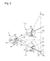
- the object location system represented very schematically in the figure 1 comprises a search device D1 and at least one target device D2.
- the search device D1 is incorporated in a portable device 11 and comprises a transceiver UWB technology, with two antennas A1 and A2.
- the target device D2 is attached to an object 12, for example a set of keys, and comprises a transceiver UWB technology, with an antenna A3.
- the drawing further shows that in most of the respective positions of the devices D1 and D2, the distance between the antennas A1 and A3 differs from that between the antennas A2 and A3, therefore the respective travel times t1 and t2 of the UWB signals on these distances are different.
- the portable apparatus 11 containing the search device D1 is an electronic watch, in particular a wristwatch, having manual control members 13 such as pushers and / or a control rod and / or a touch screen.
- the electronic assembly 14 of the search device is housed inside the sealed box of the watch 11 and can be powered by the same battery as the watch. Thanks to the very high frequency (of the order of 3.1 to 10 GHz) used in UWB, the size of the antennas is very small. It is possible to use antennas of the coplanar type (microstrip).
- the antennas A1 and A2 have diametrically opposed locations, so that their spacing d0 measured along the axis 15 passing through the central point of each of the two antennas is as large as possible.
- the antennas may be housed with the watch components inside thereof.
- a value of d0 between 3 and 4 cm is quite compatible with the usual size of a wristwatch and with the necessary precision in the measurements and calculations described below.
- one of the advantages of incorporating the search device D1 in a watch is its permanent availability, since the user generally wears his watch all day.
- Another advantage lies in the possibility of using the usual display members of an electronic watch for the indications provided by the search device, since the watch includes an analog time display, which allows indicate directions by means of the hands.
- a numerical or alphanumeric display provided, for example, to indicate the date or a timed time, makes it possible to indicate the distance of the object sought, but this distance could also be indicated in an analog way, for example by means of a pointer. chronograph counter.
- the synergy between the research device and the wristwatch is very high since the sealed housing, the power supply, the display means, the manual control means and the wrist strap are all in common. the user.
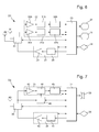
- the antennas A1 and A2 are alternately connected to a UWB transmitter module 21 and to a UWB receiver module 22.
- the modules 21 and 22 are connected to a digital processing module 23, itself connected.
- the input key 24 is a manual control, for example actuated by one of the buttons 13 of the watch or by the touch screen.
- the UWB transmitter module 21 comprises a UWB pulse generator 28 and an amplifier 29 whose output signal reaches simultaneously to the two antennas A1 and A2 through the switch 20.
- the UWB receiver module 22 comprises two parallel chains respectively receiving the signals of the antennas A1 and A2 and each comprising an amplifier 30a, 30b, a energy detector 31a, 31b and a demodulator 32a, 32b which delivers its output signal to the digital processing module 23. This coordinates the operation of the elements 20, 21 and 22 with the digital links drawn in dotted lines, performs the operations described below to calculate the position of the searched object and controls the displays 25 and 26 to indicate this position.
- the electronic assembly of the target device D2 comprises a UWB transmitter module 34 and a UWB receiver module 35 which are alternatively connected to the antenna A3 by a transmission / reception switch 36.
- the modules 34 and 35 are connected to a processing module 37, which is itself connected to an input key 38 and, optionally, to an acoustic transducer 39.
- the UWB transmitter module 34 comprises a UWB pulse generator 41 and an amplifier 42 whose output signal reaches the receiver. Antenna A3 through the switch 36.
- the UWB receiver module 35 comprises an amplifier 43, a power detector 44 and a demodulator 45 which delivers its output signal to the digital processing module 37. This coordinates the operation of the elements 34. , 35 and 36 by digital signals on the dotted lines, performs the operations described below for transmitting UWB signals in response to the received signals, and produces a warning signal to be broadcast by the acoustic transducer 39 if it is present.
- a wake-up receiver 46 which also receives the signals picked up by the antenna A3 and controls the activation of the receiver module 35 only after receiving a coded wake-up signal.
- the structure and operation of such a wake-up receiver are known. An example of realization is described in the article entitled "At 2GHz 52 ⁇ W Wake-Up Receiver With -72dBm Sensitivity Using Uncertain-IF Architecture," by N. Pletcher et al, 2008 IEEE International Solid-State Circuits Conference, Digest of Technical Papers, p. 524-525 .
- the basic structure is very simple. It is an envelope detector calibrated at the frequency of interest.
- the received wake-up signal is an amplitude-modulated signal, with an information sequence (code) identifying the device to be woken up.
- code information sequence
- the power supply with a miniature battery makes it possible to keep such a receiver idle for a period of several years, depending on the duty cycle chosen.
- the module 37 furthermore comprises a non-volatile memory in which the code representing the identity of the target device D2 is recorded, in order to distinguish it from other similar target devices D3, D4 and so on. likely to be located using the same search device D1.
- This identity code of D2 must be stored in a memory of D1 during a declaration operation, controlled for example by a combination of actions on the input key 38, before the search device can be used. to locate this target device. The same is true for the identity codes of the other target devices D3, D4 and so on. which one would like to add to the system, if any.
- the operation of the system will now be described for locating the object 12 linked to the target device D2 with reference to the Figures 3 to 8 .
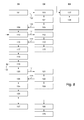
- the scheme of the figure 8 represents the operational steps performed in or by the devices D1, D2 and D3 (if it is present in the vicinity) for a location operation of the object 12.
- the search device D1 sends a wake up signal 102 containing the identity code of the target device D2.
- the latter receives and recognizes the signal 102 in the step 103 by means of its receiver of wakeup 46, which activates the remainder of the D2 electronics in step 104.
- D2 transmits an acknowledgment signal 106 which also contains its identity code.
- the other target device D3 also received the wake up signal 102 at 107 because it was close enough, but its wake-up receiver does not recognize its identity in this signal, so D3 remains inactive at 108.
- the search device D1 receives the signal 106 in the step 109 and then begins a first location sequence, by a step 110 consisting in developing a location signal 111, which also contains the identity code of D2, and transmitting it simultaneously on its two antennas A1 and A2 as shown in figure 5 at a time tini which begins a countdown of the time in a clock circuit 50 of D1.
- a step 110 consisting in developing a location signal 111, which also contains the identity code of D2, and transmitting it simultaneously on its two antennas A1 and A2 as shown in figure 5 at a time tini which begins a countdown of the time in a clock circuit 50 of D1.
- the antenna A3 of the target device is closer to the antenna A1 than to the antenna A2, that is to say that the travel time t1 of the location signal 111 between A1 and A3 is shorter than its travel time t2 between A2 and A3.
- D2 generates and transmits at the instant tpktTx3 (see figure 5 ) a return signal 114 which contains the time difference tdiff and a processing time tproc which is the time interval between tpktRx1 and tpktTx3.
- D2 may perform a step 115 of emitting a sound signal via its acoustic transducer 39, to help locate the object sought through hearing if the conditions allow.
- the search device D1 receives the return signal 114 in the first place at a time tfin1 (see figure 5 ) by its antenna A1 closest to the antenna A3. This reception activates a switch that temporarily isolates the antenna A2 from its receiver UWB, so that it does not work at time tfin2 where the same signal will be received by the antenna A2, to reduce the energy consumption of D1.
- the value tdist tfin1-tini is measured by means of a clock circuit.
- This module calculates, by triangulation in the plane of the three antennas from the values of d0, d1 and d2, the polar coordinates of the position or possible positions of the antenna A3 and thus of the object sought 12 with reference to the watch and its axis 15, then controls a corresponding visual indication by the display means 25 and 26 of the watch 11 in step 118. Note that if t1> t2, it is necessary to switch the indices 1 and 2 in the formulas above.
- the absolute value of d2-d1 is less than d0 and the aforementioned triangulation calculation provides two possible positions, symmetrical with respect to the axis 15 and referenced P and Q in the figure 3 .
- the respective directions of these positions are indicated by the hour hand 51 and the minute hand 52 of the analog display 25, while their common distance (here 4.9 m) is indicated by the 26.
- the new position 11a is reached by a translation movement.
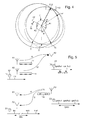
- the figure 4 shows an embodiment of said movement as a limited rotation of the watch 11 in the plane of its dial so to change the orientation of its reference axis 15 without translation, so without changing location.
- the watch 11 is represented only by its pair of antennas A1 and A2.
- the frame of reference of the drawing is the earth.
- the two possible positions of the object according to the first measurement are indicated by the points P and Q.
- the new positions A1 'and A2' of the antennas define a new position 15 'of their reference axis, so that the memorized coordinates of the points P and Q define points P 'and Q', angularly shifted from w from P and Q.
- the device D1 then performs a second location sequence, comprising steps 120 to 125 which are similar to steps 110, 112, 113, 115, 116 and 117 of the first sequence, but with additional calculations in step 125.
- This sequence is preferably triggered automatically, after a period of time for example between a few tenths of a second and a few seconds after step 117, but one could also consider doing it by manual control.
- the triangulation calculation performed in D1 generally provides, as before, two possible positions of the sought object 12, indicated here by the points S and T. which represents the position of the object 12 is the one which coincides practically with P or Q, so S coinciding with P in the case of the figure 4 .
- D1 In the repository based on the axis 15 ', D1 must select in step 125 that of points S and T which is angularly offset from -w with respect to P' and Q ', respectively. It then controls a visual indication of the position of the object sought 12 by the display means of the watch in step 126, the direction of this position being indicated by the two needles 51 and 52 superimposed, while the distance is indicated by the digital display 26.
- D1 could record their coordinates in place of those of P and Q, then perform a new location sequence from step 120.
- the search is deemed complete and D1 automatically stops at 127.
- An end of search command is performed in the target device D2 in a step 128. It can be done automatically, for example by a timer, or by a manual action on the input key 38. D2 is then found in 129 in a standby state where only its wake-up receiver is powered.
- another operating mode of the search device D1 may be provided, with a periodic repetition of the locating sequence in different successive positions of the watch 11, while the user himself interprets the movements of the watch hands. compared to the environment. There is no need to execute steps 120-127.
- the continuous repetition of the location sequence is optionally represented by the arrow 130 in the figure 8 and can be done, for example, at a rate of the order of half a second to a second.
- the new sequence (steps 110-118) overwrites the stored position data and results in displaying a new distance and (usually) two possible new directions of the searched object 12.
- the search device is arranged to discriminate which of the two directions is the right one, since the user can do it himself by observing the evolution of the display.
- the interpretation can be facilitated when the user moves the watch in the direction of one of the needles: if this needle remains in the same direction of the space, it is that the watch goes well towards the sought object.
- This procedure is represented in the figure 3 . If the user, starting from the initial position of the watch 11, moves the latter in the direction of the large needle 52 to 11a, the new location sequence will move the two needles, so that the small 51 point in this case to the actual position P of the object 12 and the large 52 to the symmetrical point Qa of P with respect to the new situation 15a of the reference axis. Seeing that the two needles have changed direction, the user must deduce that the translation was not made in the right direction.
- this needle pointing to P does not change direction and it follows that the translation is well made in the direction of the object 12.
- the large needle 52 pointing to the symmetrical point Qb of P with respect to the position 15b of the reference axis, rotates only if the orientation of this axis changes. Again, the user can rotate the watch until both hands are superimposed. He will then have to put an end to the localization iterations by a manual action on the control organs of the watch.
- the search device D1 may be provided with an inertial unit comprising for example an accelerometer with at least two axes and a gyroscope, in order to calculate the movements undergone by the watch in the plane of the dial, generally kept horizontal.
- an inertial unit comprising for example an accelerometer with at least two axes and a gyroscope, in order to calculate the movements undergone by the watch in the plane of the dial, generally kept horizontal.
- a first location sequence with the stationary watch 11 at position 11c provides the coordinates of the points P and Q in the frame of the watch, P being the position of the antenna of the target device D2 attached to the object 12, while Q is the symmetrical point of P with respect to the position 15c of the reference axis of the watch.
- the search device While the user imposes on the watch a movement M, the search device periodically measures the components of this movement by means of the accelerometer and the gyroscope, recalculates the coordinates of P and Q with respect to the new position of its repository and orients the needles 51 and 52 accordingly, as seen in the intermediate position 11d.
- a second location sequence similar to that described with reference to the figure 8 , is then started automatically or manually in any position 11 th of the watch. It enables the search device D1 to discriminate between the actual position P of the object 12 and that of its symmetrical image with respect to the current position 15e of the reference axis, and to indicate the direction of the object by superimposition of the two needles 51 and 52 while indicating its distance on the digital display 26. The user thus knows where the object is located and can, at its discretion, continue the search by UWB closer or terminate.
- the invention makes it possible to realize a location system integrating with very small devices, so that the target devices can be attached discreetly to the objects to be searched and that a user can easily keep the device search with him when needed.
- the latter is not necessarily combined with a watch; it may also be considered to be incorporated into an apparatus intended solely for that purpose or to another portable apparatus containing a source of electrical energy, electronic circuits and display means capable of indicating two directions and a distance, by example a mobile phone or nomadic satellite positioning device.
Abstract
Description
La présente invention concerne un procédé de localisation d'un objet cherché au moyen de signaux électromagnétiques échangés entre un dispositif de recherche, incorporé à un appareil portable, et un dispositif cible attaché à l'objet cherché, le dispositif de recherche comportant un émetteur-récepteur associé à une paire d'antennes espacées l'une de l'autre, des moyens d'affichage, des moyens électroniques pour gérer l'émetteur-récepteur et les moyens d'affichage, et des moyens manuels de commande, le dispositif cible comportant un émetteur-récepteur associé à une antenne et à des moyens électroniques capables de détecter la réception de signaux provenant du dispositif de recherche et d'y répondre par des signaux représentant notamment l'identité du dispositif cible.The present invention relates to a method of locating a searched object by means of electromagnetic signals exchanged between a search device, incorporated in a portable device, and a target device attached to the searched object, the search device comprising a transmitter receiver associated with a pair of antennas spaced from each other, display means, electronic means for managing the transceiver and the display means, and manual control means, the target device comprising a transceiver associated with an antenna and with electronic means capable of detecting the reception of signals from the search device and of responding to them by signals representing in particular the identity of the target device.
L'invention concerne également un système de localisation spécialement conçu pour la mise en oeuvre dudit procédé, ainsi qu'un dispositif de recherche faisant partie d'un tel système de localisation.The invention also relates to a location system specially designed for implementing said method, as well as to a search device forming part of such a location system.
Il arrive de perdre un objet d'usage courant, ou surtout d'oublier à quel endroit on l'a laissé alentour, par exemple dans une habitation ou un lieu de travail. Si l'objet est de petite taille, comme un trousseau de clés ou des lunettes, sa recherche peut être difficile et en tout cas fastidieuse. C'est pourquoi différents systèmes de localisation par transmission sans fil ont déjà été proposés. La présente invention prévoit d'utiliser la technologie sans fil UWB (ultra wide band) dans un tel système. Les principaux avantages de cette technologie dans la localisation d'objets à courte distance sont mentionnés dans la demande de brevet
La demande de brevet
Un autre système utilisant des signaux UWB pour localiser un objet à courte distance est décrit dans la demande de brevet
Le terminal mobile émet ses signaux caractéristiques UWB sur commande, soit par pression manuelle sur une touche, soit automatiquement en réponse à une requête de localisation, envoyée par exemple par SMS, ou en réponse à la détection d'une situation dangereuse par le terminal lui-même. Pour localiser le terminal mobile au moyen de ses signaux UWB, le dispositif de recherche comporte quatre antennes disposées aux sommets d'un losange et associées par paires à une électronique qui mesure les différences de temps de réception du signal UWB dans chaque paire d'antennes. A partir de ces mesures, le dispositif de recherche calcule les coordonnées orthogonales du terminal mobile par rapport au référentiel défini par les quatre antennes, puis les coordonnées polaires (azimut et distance) et affiche ces dernières au moyen d'une aiguille et d'un affichage numérique.The mobile terminal transmits its characteristic UWB signals on command, either by manual pressure on a key, or automatically in response to a location request, sent for example by SMS, or in response to the detection of a dangerous situation by the terminal itself. -even. To locate the mobile terminal by means of its UWB signals, the search device comprises four antennas arranged at the vertices of a rhombus and paired with an electronics which measures the differences in the reception time of the UWB signal in each pair of antennas. . From these measurements, the search device calculates the orthogonal coordinates of the mobile terminal with respect to the reference defined by the four antennas, then the polar coordinates (azimuth and distance) and displays the latter by means of a needle and a digital display.
Le système divulgué dans le document précité
La présente invention vise à fournir un procédé et un système de localisation d'objet qui permettent d'éviter substantiellement les inconvénients de l'art antérieur. Le dispositif cible devrait être réalisable sous une assez petite taille pour être associé discrètement à l'objet concerné, par exemple sous la forme d'une plaquette ou d'une étiquette collée. La mise en marche du dispositif cible pour répondre au dispositif de recherche devrait pouvoir se faire sans autre action que la réception de signaux provenant du dispositif de recherche. Un autre but de l'invention est de combiner le dispositif de recherche avec un appareil électronique portable dont il utilise certains composants, afin d'arriver à une miniaturisation poussée et de permettre à l'utilisateur d'avoir le dispositif de recherche constamment à sa disposition et de le porter sans subir de gêne.The present invention aims to provide an object locating method and system that substantially avoids the disadvantages of the prior art. The target device should be feasible under a relatively small size to be discreetly associated with the object concerned, for example in the form of a wafer or a glued label. The start of the target device to respond to the search device should be able to be done without any action other than the reception of signals from the search device. Another object of the invention is to combine the search device with a portable electronic device which it uses certain components, in order to achieve a miniaturization thrust and to allow the user to have the search device constantly at his disposal and to wear it without suffering from uncomfortable.
Selon un premier aspect de l'invention, il est prévu un procédé de localisation tel que spécifié dans la revendication 1 ci-jointe. Les revendications dépendantes 2 à 6 définissent des modes de réalisation particuliers du procédé selon l'invention.According to a first aspect of the invention, there is provided a locating method as specified in claim 1 attached. Dependent claims 2 to 6 define particular embodiments of the method according to the invention.
Selon d'autres aspects de l'invention, la revendication 7 définit un système de localisation d'objets pour la mise en oeuvre de ce procédé, tandis que la revendication 11 définit un dispositif de recherche pour la mise en oeuvre de ce procédé.According to other aspects of the invention, claim 7 defines an object locating system for carrying out this method, while
En combinant la transmission en UWB exclusivement et l'utilisation d'un signal de réveil UWB pour activer le dispositif cible, il devient possible de garder ce dernier en état de veille sur une très longue durée, typiquement plusieurs années, avec une faible quantité d'énergie électrique. Le dispositif cible, utilisant une seule bande de fréquence et une unique antenne UWB, peut être réalisé sous une forme bien plus réduite que selon l'art antérieur et être attaché à des objets de petite taille, comme un porte-clés, un portefeuille ou des lunettes. La consommation d'énergie du dispositif de recherche est aussi notablement réduite. En combinaison avec l'utilisation d'une seule paire d'antennes, de faible taille et éloignées de quelques centimètres seulement compte tenu de la fréquence très élevée des signaux UWB, cela permet d'incorporer le dispositif de recherche dans un appareil portable de petite taille.By combining the UWB transmission exclusively and the use of a UWB wake-up signal to activate the target device, it becomes possible to keep the latter in a standby state over a very long period, typically several years, with a small amount of 'electric energy. The target device, using a single frequency band and a single UWB antenna, can be made in a much smaller form than in the prior art and can be attached to small objects, such as a key ring, wallet or glasses. The energy consumption of the search device is also significantly reduced. In combination with the use of a single pair of antennas, small in size and only a few centimeters apart, given the very high frequency of the UWB signals, this makes it possible to incorporate the search device into a small portable device. cut.
Dans un mode de réalisation préféré, comme le lecteur pourra mieux le constater plus loin, l'invention permet avantageusement de loger le dispositif de recherche dans une boîte de montre-bracelet de taille normale et d'utiliser les organes d'affichage du temps pour indiquer la position de l'objet cherché. C'est ainsi que l'utilisateur, portant sa montre comme d'habitude, disposera immédiatement du dispositif de recherche quand il en aura besoin.In a preferred embodiment, as the reader can better see below, the invention advantageously allows the search device to be housed in a normal size wristwatch box and to use the time display devices for indicate the position of the object sought. This is how the user, wearing his watch as usually, will immediately have the search device when they need it.
D'autres particularités et avantages de l'invention apparaîtront ci-dessous dans la description de divers modes de réalisation, présentés à titre d'exemples non limitatifs en référence aux dessins annexés.Other features and advantages of the invention will appear below in the description of various embodiments, presented as non-limiting examples with reference to the accompanying drawings.
-
La
figure 1 représente schématiquement deux éléments constituant la base du système de localisation, à savoir un dispositif de recherche D1 incorporé à un appareil portable et un dispositif cible D2 attaché à un objet cherché.Thefigure 1 schematically represents two elements constituting the base of the location system, namely a search device D1 incorporated in a portable device and a target device D2 attached to a sought object. -
La
figure 2 représente schématiquement le dispositif de recherche D1, incorporé à une montre-bracelet.Thefigure 2 schematically represents the search device D1, incorporated in a wristwatch. -
La
figure 3 représente schématiquement différentes étapes du procédé de localisation, dans un mode opératoire avec translation du dispositif de recherche.Thefigure 3 schematically represents different steps of the localization method, in a mode of operation with translation of the search device. -
La
figure 4 représente schématiquement des étapes successives du procédé de localisation, dans un mode opératoire avec rotation du dispositif de recherche.Thefigure 4 schematically represents successive steps of the localization method, in a mode of operation with rotation of the search device. -
La
figure 5 représente schématiquement deux phases successives d'une séquence de localisation par échange de signaux UWB entre le dispositif de recherche et le dispositif cible.Thefigure 5 schematically represents two successive phases of a UWB signal exchange location sequence between the search device and the target device. -
La
figure 6 est un schéma-bloc du dispositif de recherche D1.Thefigure 6 is a block diagram of the search device D1. -
La
figure 7 est un schéma-bloc du dispositif cible D2.Thefigure 7 is a block diagram of the target device D2. -
La
figure 8 est un schéma des étapes du fonctionnement du système desfigures 1 à 7 pour une opération de localisation d'un objet.Thefigure 8 is a diagram of the steps in the operation of the system ofFigures 1 to 7 for an operation of locating an object. -
La
figure 9 représente schématiquement des étapes successives du procédé de localisation, dans une variante où le dispositif de recherche contient un accéléromètre.Thefigure 9 schematically represents successive steps of the localization method, in a variant where the search device contains an accelerometer.
Le système de localisation d'objets représenté très schématiquement dans la
Dans le mode de réalisation préféré illustré par la
On se référera à la
Le module émetteur UWB 21 comporte un générateur d'impulsions UWB 28 et un amplificateur 29 dont le signal de sortie parvient simultanément aux deux antennes A1 et A2 à travers le commutateur 20. Le module récepteur UWB 22 comporte deux chaines parallèles recevant respectivement les signaux des antennes A1 et A2 et comprenant chacune un amplificateur 30a, 30b, un détecteur d'énergie 31 a, 31 b et un démodulateur 32a, 32b qui délivre son signal de sortie au module de traitement numérique 23. Celui-ci coordonne le fonctionnement des éléments 20, 21 et 22 grâce aux liaisons numériques dessinées en pointillés, effectue les opérations décrites plus loin pour calculer la position de l'objet cherché et commande les affichages 25 et 26 pour indiquer cette position.The
En référence à la
Afin que D2 consomme très peu d'énergie à l'état de veille, il comporte un récepteur de réveil 46 qui reçoit également les signaux captés par l'antenne A3 et ne commande la mise en fonction du module récepteur 35 qu'après réception d'un signal de réveil codé. La structure et le fonctionnement d'un tel récepteur de réveil sont connus. Un exemple de réalisation est décrit dans l'article intitulé
Le module 37 comporte en outre une mémoire non volatile dans laquelle est enregistré le code représentant l'identité du dispositif cible D2, afin de le distinguer d'autres dispositifs cibles semblables D3, D4 etc. susceptibles d'être localisés au moyen du même dispositif de recherche D1. Ce code d'identité de D2 doit être enregistré dans une mémoire de D1 au cours d'une opération de déclaration, commandée par exemple par une combinaison d'actions sur la touche d'entrée 38, avant que le dispositif de recherche puisse être utilisé pour localiser ce dispositif cible. Il en va de même pour les codes d'identité des autres dispositifs cibles D3, D4 etc. que l'on voudrait ajouter au système, le cas échéant.The
On décrira maintenant le fonctionnement du système pour localiser l'objet 12 lié au dispositif cible D2 en référence aux
Dans la première étape 101, que l'utilisateur amorce par un actionnement approprié des organes de commande 13 (voir
Le dispositif de recherche D1 reçoit le signal 106 dans l'étape 109 et commence alors une première séquence de localisation, par une étape 110 consistant à élaborer un signal de localisation 111, contenant aussi le code d'identité de D2, et l'émettre simultanément sur ses deux antennes A1 et A2 comme le montre la
Dans l'étape 116, le dispositif de recherche D1 reçoit le signal de retour 114 en premier lieu à un instant tfin1 (voir
Dans l'étape 117, le module 23 de D1 calcule les temps de parcours : ![]()
![]()
qui représentent les distances correspondantes d1 et d2 entre l'antenne A3 et chaque antenne A1 et A2. Ce module calcule ensuite, par triangulation dans le plan des trois antennes à partir des valeurs de d0, d1 et d2, les coordonnées polaires de la position ou des positions possibles de l'antenne A3 et donc de l'objet cherché 12 en référence à la montre et son axe 15, puis commande une indication visuelle correspondante par les moyens d'affichage 25 et 26 de la montre 11 dans l'étape 118. On notera que si t1>t2, il convient de permuter les indices 1 et 2 dans les formules ci-dessus.In ![]()
![]()
which represent the corresponding distances d1 and d2 between the antenna A3 and each antenna A1 and A2. This module then calculates, by triangulation in the plane of the three antennas from the values of d0, d1 and d2, the polar coordinates of the position or possible positions of the antenna A3 and thus of the object sought 12 with reference to the watch and its
En général, la valeur absolue de d2-d1 est inférieure à d0 et le calcul de triangulation susmentionné fournit deux positions possibles, symétriques par rapport à l'axe 15 et référencées P et Q dans la
La
Après une rotation limitée w de la montre 11, par exemple dans le sens horaire, les nouvelles positions A1' et A2' des antennes définissent une nouvelle position 15' de leur axe de référence, si bien que les coordonnées mémorisées des points P et Q définissent des points P' et Q', décalés angulairement de w à partir de P et Q. Le dispositif D1 effectue alors une seconde séquence de localisation, comprenant des étapes 120 à 125 qui sont semblables aux étapes 110, 112, 113, 115, 116 et 117 de la première séquence, mais avec des calculs complémentaires dans l'étape 125. Cette séquence est enclenchée de préférence automatiquement, après un délai compris par exemple entre quelques dixièmes de seconde et quelques secondes après l'étape 117, mais on pourrait aussi envisager de le faire par commande manuelle. La position réelle de l'objet cherché 12 n'ayant pas changé sur la terre, le calcul de triangulation effectué dans D1 fournit en général comme précédemment deux positions possibles de l'objet cherché 12, indiquées ici par les points S et T. Celui qui représente la position de l'objet 12 est celui qui coïncide pratiquement avec P ou Q, donc S coïncidant avec P dans le cas de la
La discrimination entre S et T en fonction du sens du décalage angulaire de chaque point, respectivement à partir de P' et Q', nécessite que soit indiqué au dispositif de recherche D1 le sens de la rotation que la montre 11 subit entre les deux séquences de localisation. Une solution simple et économique consiste à prescrire le sens de cette rotation dans le mode d'emploi, par exemple le sens horaire. Autrement, on pourrait incorporer un gyroscope dans D1, mais cela impliquerait une complication relativement coûteuse et un surcroît de consommation d'énergie. Par contre, le gyroscope permettrait de maintenir la direction des aiguilles par rapport à l'environnement quand l'orientation de la montre change après la mesure.The discrimination between S and T as a function of the direction of the angular displacement of each point, respectively from P 'and Q', requires that indicated to the search device D1 the direction of rotation that the
Si pour une raison quelconque la discrimination entre S et T n'était pas possible, D1 pourrait enregistrer leurs coordonnées à la place de celles de P et Q, puis effectuer une nouvelle séquence de localisation à partir de l'étape 120. Par contre, quand l'affichage a été fait normalement dans l'étape 126, la recherche est réputée achevée et D1 s'arrête automatiquement en 127. Une commande de fin de recherche est effectuée dans le dispositif cible D2 dans une étape 128. Elle peut se faire automatiquement, par exemple par une temporisation, ou par une action manuelle sur la touche d'entrée 38. D2 se retrouve alors en 129 dans un état de veille où seul son récepteur de réveil est sous tension.If for some reason the discrimination between S and T was not possible, D1 could record their coordinates in place of those of P and Q, then perform a new location sequence from
En variante, on peut prévoir un autre mode opératoire du dispositif de recherche D1, avec une répétition périodique de la séquence de localisation dans différentes positions successives de la montre 11, tandis que l'utilisateur interprète lui-même les mouvements des aiguilles de la montre par rapport à l'environnement. Il n'y a pas besoin d'exécuter les étapes 120 à 127. La répétition continue de la séquence de localisation est représentée de manière optionnelle par la flèche 130 dans la
L'interprétation peut être facilitée lorsque l'utilisateur déplace la montre dans la direction d'une des aiguilles: si cette aiguille reste dans la même direction de l'espace, c'est que la montre va bien vers l'objet cherché. Ce mode opératoire est représenté dans la
Un mode opératoire analogue est applicable avec des mouvements de rotation sans translation. Dans l'exemple de la
Il importe de noter que le mode opératoire décrit ci-dessus n'est pas limité à des mouvements de pure rotation ou de pure translation de la montre, car il reste utilisable quand la montre effectue des combinaisons de translations et de rotations. Pour que l'utilisateur interprète correctement les mouvements des aiguilles, il suffit que le cadran de la montre reste approximativement dans un même plan, par exemple horizontal.It is important to note that the procedure described above is not limited to movements of pure rotation or pure translation of the watch, because it remains usable when the watch performs combinations of translations and rotations. In order for the user to correctly interpret the movements of the hands, it suffices that the dial of the watch remains approximately in the same plane, for example horizontal.
Selon un autre mode de réalisation du dispositif de recherche D1, qui n'est pas décrit en détail ici, celui-ci peut être pourvu d'une centrale inertielle comportant par exemple un accéléromètre à au moins deux axes et un gyroscope, afin de calculer les mouvements subis par la montre dans le plan du cadran, en général maintenu horizontal. Cela permet au dispositif, au moment d'une nouvelle séquence de localisation, de transformer les coordonnées des deux points mémorisés lors de la séquence précédente en coordonnées dans son référentiel déplacé et de les comparer à celles des deux nouveaux points afin de trouver lequel n'a pas bougé. Le mode opératoire d'un tel dispositif est illustré par la
Pendant que l'utilisateur impose à la montre un mouvement M, le dispositif de recherche mesure périodiquement les composantes de ce mouvement au moyen de l'accéléromètre et du gyroscope, recalcule les coordonnées de P et Q par rapport à la nouvelle position de son référentiel et oriente en conséquence les aiguilles 51 et 52, comme on le voit dans la position intermédiaire 11 d. Une seconde séquence de localisation, analogue à celle décrite en référence à la
La description qui précède montre que l'invention permet de réaliser un système de localisation s'intégrant à des appareils très peu encombrants, de sorte que les dispositifs cibles puissent être attachés discrètement aux objets à rechercher et qu'un utilisateur puisse aisément garder le dispositif de recherche avec lui en cas de besoin. Ce dernier n'est pas nécessairement combiné à une montre; on peut aussi envisager de l'incorporer à un appareil destiné seulement à cet usage ou à un autre appareil portable contenant une source d'énergie électrique, des circuits électroniques et des moyens d'affichage capables d'indiquer deux directions et une distance, par exemple un téléphone mobile ou un appareil nomade de positionnement par satellites.The foregoing description shows that the invention makes it possible to realize a location system integrating with very small devices, so that the target devices can be attached discreetly to the objects to be searched and that a user can easily keep the device search with him when needed. The latter is not necessarily combined with a watch; it may also be considered to be incorporated into an apparatus intended solely for that purpose or to another portable apparatus containing a source of electrical energy, electronic circuits and display means capable of indicating two directions and a distance, by example a mobile phone or nomadic satellite positioning device.
Claims (13)
ce procédé étant caractérisé en ce que lesdits signaux sont uniquement des signaux UWB et en ce qu'il comporte les phases successives suivantes :
this method being characterized in that said signals are only UWB signals and in that it comprises the following successive phases:
ce système étant caractérisé en ce que les signaux échangés entre le dispositif de recherche (D1) et le dispositif cible (D2) sont des signaux UWB ; en ce que le dispositif cible (D2) comporte, en plus dudit émetteur-récepteur (34, 35), un récepteur de réveil (46) agencé pour recevoir et décoder un signal de réveil UWB dans un état de veille du dispositif cible et, lorsque le signal de réveil contient le code d'identité du dispositif cible, mettre en service ledit émetteur-récepteur (34, 35) ; et en ce que les moyens d'affichage du dispositif de recherche (D1) comportent deux aiguilles (51, 52), capables d'indiquer ensemble deux directions simultanément ou une seule direction en étant superposées.An object locating system for carrying out the method according to claim 1, comprising a search device (D1), incorporated in a portable apparatus (11), and at least one target device (D2) attached to a searched object (12); the search device (D1) comprising a transceiver (21, 22) associated with a pair of antennas (A1 and A2) spaced apart from each other, display means (25, 26) for indicating at least one direction and a distance, electronic means (23) for managing the transceiver and the display means, and manual control means (24); the target device (D2) comprising a transceiver (34, 35) associated with an antenna (A3) and electronic means (37) capable of detecting and responding to the reception of signals from the search device; signals representing in particular the identity of the target device;
this system being characterized in that the signals exchanged between the search device (D1) and the target device (D2) are UWB signals; in that the target device (D2) comprises, in addition to said transceiver (34, 35), an alarm receiver (46) arranged to receive and decode a UWB wake-up signal in a standby state of the target device and, when the wake-up signal contains the identity code of the target device, provisioning said transceiver (34, 35); and in that the display means of the search device (D1) comprise two needles (51, 52) capable of indicating together two directions simultaneously or a single direction while being superposed.
ce dispositif étant caractérisé en ce que l'émetteur-récepteur (21, 22) est un émetteur-récepteur UWB et en ce que ses moyens d'affichage comportent deux aiguilles (51, 52) capables d'indiquer ensemble deux directions simultanément ou une seule direction en étant superposées.Search device (D1) for implementing the object locating method according to claim 1, comprising a transceiver (21, 22) associated with a pair of antennas (A1 and A2) spaced apart from each other. the other, display means (25, 26) for indicating a direction and a distance, electronic means (23) for managing the transceiver and the display means, and manual control means (24); );
this device being characterized in that the transceiver (21, 22) is a UWB transceiver and in that its display means comprise two needles (51, 52) capable of simultaneously indicating two directions simultaneously or a only direction by being superimposed.
Priority Applications (8)
| Application Number | Priority Date | Filing Date | Title |
|---|---|---|---|
| EP10156749A EP2367021A1 (en) | 2010-03-17 | 2010-03-17 | Method and system for locating objects |
| EP11156588.3A EP2367022B1 (en) | 2010-03-17 | 2011-03-02 | Method and system for locating objects |
| TW100107574A TWI524084B (en) | 2010-03-17 | 2011-03-07 | Method of locating objects |
| JP2011053578A JP5379939B2 (en) | 2010-03-17 | 2011-03-10 | Method and system for locating search object |
| CN201110062989.5A CN102193081B (en) | 2010-03-17 | 2011-03-16 | Method and system for locating objects |
| KR1020110023759A KR101349418B1 (en) | 2010-03-17 | 2011-03-17 | Method and system of locating objects |
| US13/050,626 US8624774B2 (en) | 2010-03-17 | 2011-03-17 | Method and system of locating objects |
| HK12102609.5A HK1162204A1 (en) | 2010-03-17 | 2012-03-14 | Method and system for locating objects |
Applications Claiming Priority (1)
| Application Number | Priority Date | Filing Date | Title |
|---|---|---|---|
| EP10156749A EP2367021A1 (en) | 2010-03-17 | 2010-03-17 | Method and system for locating objects |
Publications (1)
| Publication Number | Publication Date |
|---|---|
| EP2367021A1 true EP2367021A1 (en) | 2011-09-21 |
Family
ID=42610064
Family Applications (2)
| Application Number | Title | Priority Date | Filing Date |
|---|---|---|---|
| EP10156749A Withdrawn EP2367021A1 (en) | 2010-03-17 | 2010-03-17 | Method and system for locating objects |
| EP11156588.3A Active EP2367022B1 (en) | 2010-03-17 | 2011-03-02 | Method and system for locating objects |
Family Applications After (1)
| Application Number | Title | Priority Date | Filing Date |
|---|---|---|---|
| EP11156588.3A Active EP2367022B1 (en) | 2010-03-17 | 2011-03-02 | Method and system for locating objects |
Country Status (7)
| Country | Link |
|---|---|
| US (1) | US8624774B2 (en) |
| EP (2) | EP2367021A1 (en) |
| JP (1) | JP5379939B2 (en) |
| KR (1) | KR101349418B1 (en) |
| CN (1) | CN102193081B (en) |
| HK (1) | HK1162204A1 (en) |
| TW (1) | TWI524084B (en) |
Families Citing this family (29)
| Publication number | Priority date | Publication date | Assignee | Title |
|---|---|---|---|---|
| EP2870491A4 (en) * | 2012-07-06 | 2015-07-08 | Nida Tech Sweden Ab | Methods nodes and computer program for positioning of a device |
| US20140097988A1 (en) * | 2012-10-05 | 2014-04-10 | Qualcomm Incorporated | Speed estimation using delta rtt measurements and area maps |
| CN103034886B (en) * | 2012-12-03 | 2016-08-31 | 中国人民解放军济南军区72465部队 | A kind of active remote radio frequency label positioning identifying method |
| CN103197279B (en) * | 2013-03-12 | 2014-10-29 | 中国矿业大学 | Location method of cooperative location system for moving target |
| CN103399296A (en) * | 2013-08-15 | 2013-11-20 | 苏州数伦科技有限公司 | Positioning orientation system and method based on wireless communication |
| US9383426B2 (en) * | 2013-09-17 | 2016-07-05 | Farrokh Mohamadi | Real-time, two dimensional (2-D) tracking of first responders with identification inside premises |
| FR3017213B1 (en) * | 2014-01-31 | 2016-02-05 | Thales Sa | RADIOFREQUENCY METHOD AND SYSTEM FOR DETERMINING, BY TORQUE OF SPACE ENGINES, THE RELATIVE ANGULAR POSITION BETWEEN SEVERAL REMOTE SPACE DEVICES |
| EP3128345B1 (en) * | 2014-03-31 | 2019-05-01 | Murata Manufacturing Co., Ltd. | Position-detecting system |
| US10871566B2 (en) * | 2014-04-09 | 2020-12-22 | Thomas Danaher Harvey | Methods and system to assist search and interception of lost objects |
| US9995824B2 (en) * | 2014-04-09 | 2018-06-12 | Thomas Danaher Harvey | Methods and system to assist search for lost and submerged objects |
| KR102158697B1 (en) * | 2014-07-18 | 2020-09-22 | 엘지전자 주식회사 | Mobile terminal |
| CN106557124B (en) * | 2016-12-01 | 2018-05-25 | 杭州鲁尔物联科技有限公司 | A kind of wearable device, search system and method |
| KR102109043B1 (en) * | 2016-12-30 | 2020-05-28 | (주)제이비드론코리아 | A hybrid drone and a control method for it |
| CN108152806A (en) * | 2017-12-27 | 2018-06-12 | 温岭市创嘉信息科技有限公司 | A kind of article quick positioning system |
| CN109655787A (en) * | 2019-01-02 | 2019-04-19 | 京东方科技集团股份有限公司 | Positioning device and method, electronics work board, shopping cart |
| WO2020165269A1 (en) * | 2019-02-15 | 2020-08-20 | Assa Abloy Ab | Beacon circuit for use with electronic locks |
| CN110109057B (en) * | 2019-04-24 | 2021-04-20 | 广州市慧建科技有限公司 | Laser positioning system |
| KR20210030785A (en) * | 2019-09-10 | 2021-03-18 | 삼성전자주식회사 | Electronic device for determining position of external electronic device and method thereof |
| US20210231792A1 (en) | 2020-01-28 | 2021-07-29 | Nec Laboratories America, Inc. | Locating objects in indoor spaces using radio frequency backscatter tags |
| CN111405508A (en) * | 2020-02-19 | 2020-07-10 | 华为技术有限公司 | Wearable device positioning method and wearable device |
| DE102020104658A1 (en) * | 2020-02-21 | 2021-08-26 | Vr Coaster Gmbh & Co. Kg | Method for providing a virtual reality experience for at least one passenger of a ride and ride |
| CN112072327B (en) * | 2020-08-27 | 2023-12-19 | Oppo广东移动通信有限公司 | Antenna device and electronic equipment |
| CN114513567B (en) * | 2020-11-16 | 2023-03-24 | Oppo广东移动通信有限公司 | Terminal protection shell, communication tag, control method, device and system |
| CN115201748A (en) * | 2021-04-14 | 2022-10-18 | 华为技术有限公司 | Positioning method and device |
| US11756034B2 (en) * | 2021-06-25 | 2023-09-12 | Verifone, Inc. | Systems and methods for alternative payment mechanism payments using ultra-wideband radio technology |
| CN113472927A (en) * | 2021-07-01 | 2021-10-01 | 维沃移动通信有限公司 | Positioning method and electronic equipment |
| CN113791380A (en) * | 2021-09-27 | 2021-12-14 | Oppo广东移动通信有限公司 | UWB angle measurement method, terminal device, tag device, and storage medium |
| CN115333557B (en) * | 2022-07-21 | 2024-01-16 | 深圳市纽瑞芯科技有限公司 | Wake-up transceiver system of UWB equipment |
| CN115866749B (en) * | 2022-11-25 | 2023-10-31 | 北京华星北斗智控技术有限公司 | Positioning method, positioning device, electronic equipment and storage medium |
Citations (7)
| Publication number | Priority date | Publication date | Assignee | Title |
|---|---|---|---|---|
| US20030034887A1 (en) * | 2001-03-12 | 2003-02-20 | Crabtree Timothy L. | Article locator system |
| DE10237605A1 (en) * | 2002-08-16 | 2004-03-04 | Leopold Kostal Gmbh & Co Kg | Determination of the position of a transponder uses a base system with a facility to generate an electromagnetic field with a difference |
| US20060033662A1 (en) | 2004-07-27 | 2006-02-16 | Ubisense Limited | Location system |
| EP1630966A1 (en) | 2004-08-30 | 2006-03-01 | Samsung Electronics Co., Ltd. | Apparatus and method for transmitting/receiving an emergency rescue request using UWB signals |
| WO2006098791A2 (en) * | 2005-03-14 | 2006-09-21 | The Alfred E. Mann Foundation For Scientific Research | System and method for locating objects and communicating with the same |
| US20080136644A1 (en) | 1998-12-11 | 2008-06-12 | Freescale Semiconductor Inc. | Method and system for performing distance measuring and direction finding using ultrawide bandwitdh transmissions |
| WO2009040699A1 (en) * | 2007-09-26 | 2009-04-02 | Nxp B.V. | A method for classifying a transponder and/or signals originating from a transponder and reader |
Family Cites Families (55)
| Publication number | Priority date | Publication date | Assignee | Title |
|---|---|---|---|---|
| US4675656A (en) * | 1984-03-16 | 1987-06-23 | Narcisse Bernadine O | Out-of-range personnel monitor and alarm |
| US4985878A (en) * | 1988-09-12 | 1991-01-15 | Casio Computer Co., Ltd. | Electronic timepiece with analog time display unit and electrooptic data display unit |
| ATE134044T1 (en) * | 1990-06-15 | 1996-02-15 | Savi Techn Inc | METHOD AND APPARATUS FOR RADIO IDENTIFICATION AND TARGET TRACKING |
| SE465391B (en) * | 1990-07-24 | 1991-09-02 | Staffan Gunnarsson | VEHICLE DEVICE MAINTAINS POSITIONING BY AUTOMATIC FUELING |
| US5272324A (en) * | 1990-08-10 | 1993-12-21 | Interlink Technologies, Inc. | Portable scanner system with transceiver for two-way radio frequency communication |
| JPH04184191A (en) * | 1990-11-19 | 1992-07-01 | Casio Comput Co Ltd | Small-sized electronic equipment |
| JPH05119145A (en) * | 1991-10-24 | 1993-05-18 | Sony Corp | Measuring system for position of mobile body |
| CA2103288C (en) * | 1992-11-18 | 2004-08-17 | Michael John Camille Marsh | Detection of multiple articles |
| US5572192A (en) * | 1994-03-17 | 1996-11-05 | Detection Systems, Inc. | Personal security system with guard tour features |
| US5652570A (en) * | 1994-05-19 | 1997-07-29 | Lepkofker; Robert | Individual location system |
| JPH11508997A (en) * | 1995-07-05 | 1999-08-03 | モトローラ・インコーポレイテッド | Conformal power supply |
| US6812824B1 (en) * | 1996-10-17 | 2004-11-02 | Rf Technologies, Inc. | Method and apparatus combining a tracking system and a wireless communication system |
| CN1233327A (en) * | 1996-10-17 | 1999-10-27 | 准确定位公司 | Article tracking system |
| US20020084904A1 (en) * | 1996-12-20 | 2002-07-04 | Carlos De La Huerga | Electronic identification apparatus |
| US6814293B2 (en) * | 1997-02-10 | 2004-11-09 | Symbol Technologies, Inc. | Arrangement for and method of establishing a logical relationship among peripherals in a wireless local area network |
| US6010242A (en) * | 1998-03-16 | 2000-01-04 | Ho; Ko-Liang | Rotary switch laser indicator |
| US6243025B1 (en) * | 1998-06-10 | 2001-06-05 | Honda Giken Kogyo Kabushiki Kaisha | Moving body detection system |
| US6158884A (en) * | 1998-06-26 | 2000-12-12 | Motorola, Inc. | Integrated communicative watch |
| US6084517A (en) * | 1998-08-12 | 2000-07-04 | Rabanne; Michael C. | System for tracking possessions |
| TW396302B (en) * | 1998-09-28 | 2000-07-01 | Swatch Group Man Serv Ag | Watch comprising an electronic tourist guide |
| JP4187377B2 (en) * | 2000-02-23 | 2008-11-26 | 富士通株式会社 | Radio transceiver and radio wave radiation direction control method |
| JP3690953B2 (en) * | 2000-02-23 | 2005-08-31 | 松下電器産業株式会社 | Delivery article handling system and delivery article handling method |
| US6476756B2 (en) * | 2000-06-05 | 2002-11-05 | Tc (Bermuda) License, Ltd. | Method and apparatus to determine the direction to a transponder in a modulated backscatter communication system |
| US6747561B1 (en) * | 2000-06-20 | 2004-06-08 | Med-Datanet, Llc | Bodily worn device for digital storage and retrieval of medical records and personal identification |
| US20020044058A1 (en) * | 2000-08-17 | 2002-04-18 | Heinrich Harley Kent | Wrist mounted RFID reader and/or antenna |
| US7034683B2 (en) * | 2000-11-06 | 2006-04-25 | Loran Technologies, Inc. | Electronic vehicle product and personnel monitoring |
| US7253717B2 (en) * | 2000-11-29 | 2007-08-07 | Mobile Technics Llc | Method and system for communicating with and tracking RFID transponders |
| JP2002277539A (en) * | 2001-03-21 | 2002-09-25 | Tateyama Kagaku Kogyo Kk | Mountaineering accident sufferer search system |
| DE10155251A1 (en) * | 2001-11-09 | 2003-06-18 | Siemens Ag | Transponder system and method for distance measurement |
| US6784827B2 (en) * | 2001-12-21 | 2004-08-31 | International Business Machines Corporation | Determining a time of arrival of a sent signal |
| GB2392032B (en) * | 2002-08-15 | 2006-08-23 | Kiddielink Ltd | Locating system, device and method |
| US20040080421A1 (en) * | 2002-10-16 | 2004-04-29 | Wunderlich Neila Johnilynn | Monitoring and alert system |
| US6900731B2 (en) * | 2002-10-30 | 2005-05-31 | Bellsouth Intellectual Property Corporation | Method for monitoring and tracking objects |
| US7274295B2 (en) * | 2002-10-30 | 2007-09-25 | At&T Bls Intellectual Property, Inc. | Instantaneous mobile access to all pertinent life events |
| CN1739040A (en) * | 2002-12-16 | 2006-02-22 | 松下电器产业株式会社 | Using multiple receive antennas to determine the location of a transmitter with respect to a receiver in ultra wideband systems |
| US7042353B2 (en) * | 2003-02-03 | 2006-05-09 | Ingrid, Inc. | Cordless telephone system |
| AU2003900627A0 (en) * | 2003-02-13 | 2003-02-27 | Aleis Trakit Pty Ltd | Security systems |
| GB0325622D0 (en) * | 2003-11-03 | 2003-12-10 | Cambridge Consultants | System for determining positional information |
| US7030761B2 (en) * | 2004-03-16 | 2006-04-18 | Symbol Technologies | Multi-resolution object location system and method |
| US7180420B2 (en) * | 2004-05-25 | 2007-02-20 | Mgm Computer Systems, Inc. | System and method using triangulation with RF/LF and infrared devices for tracking objects |
| AU2005258784A1 (en) * | 2004-07-01 | 2006-01-12 | Powerid Ltd. | Battery-assisted backscatter RFID transponder |
| GB0418376D0 (en) * | 2004-08-18 | 2004-09-22 | Loc8Tor Ltd | Locating system |
| US7728713B2 (en) * | 2005-05-06 | 2010-06-01 | Intelleflex Corporation | Accurate persistent nodes |
| EP1724604B1 (en) * | 2005-05-18 | 2008-07-30 | Asulab S.A. | Apparatus and method for position determination with a GPS receiver and a compass |
| US7379015B2 (en) * | 2005-12-01 | 2008-05-27 | Trimble Navigation Limited | First responder positioning apparatus |
| US20080157970A1 (en) * | 2006-03-23 | 2008-07-03 | G2 Microsystems Pty. Ltd. | Coarse and fine location for tagged items |
| US7812719B2 (en) * | 2006-05-01 | 2010-10-12 | Djuric Petar M | RFID system and method for localizing and tracking a moving object with an RFID tag |
| KR100769673B1 (en) * | 2006-06-14 | 2007-10-24 | 삼성전자주식회사 | Position recognition method and position recognition system |
| JP2008151533A (en) * | 2006-12-14 | 2008-07-03 | Samsung Yokohama Research Institute Co Ltd | Positioning system and radio communication device |
| US8294554B2 (en) * | 2006-12-18 | 2012-10-23 | Radiofy Llc | RFID location systems and methods |
| WO2008102686A1 (en) * | 2007-02-22 | 2008-08-28 | Nec Corporation | Multiband transceiver and positioning system using the transceiver |
| JP2009002886A (en) * | 2007-06-25 | 2009-01-08 | Brother Ind Ltd | Distance measuring system and positioning system |
| US8334703B2 (en) * | 2007-11-20 | 2012-12-18 | Roiksimt | Apparatus for remote detection and monitoring of concealed objects |
| JP4593635B2 (en) * | 2008-01-24 | 2010-12-08 | 株式会社エヌ・ティ・ティ・ドコモ | Radio control station and mobile communication system for positioning |
| US8044797B2 (en) * | 2009-01-27 | 2011-10-25 | Bae Systems Information And Electronic Systems Integration Inc. | System for locating items |
-
2010
- 2010-03-17 EP EP10156749A patent/EP2367021A1/en not_active Withdrawn
-
2011
- 2011-03-02 EP EP11156588.3A patent/EP2367022B1/en active Active
- 2011-03-07 TW TW100107574A patent/TWI524084B/en not_active IP Right Cessation
- 2011-03-10 JP JP2011053578A patent/JP5379939B2/en active Active
- 2011-03-16 CN CN201110062989.5A patent/CN102193081B/en active Active
- 2011-03-17 KR KR1020110023759A patent/KR101349418B1/en active IP Right Grant
- 2011-03-17 US US13/050,626 patent/US8624774B2/en active Active
-
2012
- 2012-03-14 HK HK12102609.5A patent/HK1162204A1/en unknown
Patent Citations (7)
| Publication number | Priority date | Publication date | Assignee | Title |
|---|---|---|---|---|
| US20080136644A1 (en) | 1998-12-11 | 2008-06-12 | Freescale Semiconductor Inc. | Method and system for performing distance measuring and direction finding using ultrawide bandwitdh transmissions |
| US20030034887A1 (en) * | 2001-03-12 | 2003-02-20 | Crabtree Timothy L. | Article locator system |
| DE10237605A1 (en) * | 2002-08-16 | 2004-03-04 | Leopold Kostal Gmbh & Co Kg | Determination of the position of a transponder uses a base system with a facility to generate an electromagnetic field with a difference |
| US20060033662A1 (en) | 2004-07-27 | 2006-02-16 | Ubisense Limited | Location system |
| EP1630966A1 (en) | 2004-08-30 | 2006-03-01 | Samsung Electronics Co., Ltd. | Apparatus and method for transmitting/receiving an emergency rescue request using UWB signals |
| WO2006098791A2 (en) * | 2005-03-14 | 2006-09-21 | The Alfred E. Mann Foundation For Scientific Research | System and method for locating objects and communicating with the same |
| WO2009040699A1 (en) * | 2007-09-26 | 2009-04-02 | Nxp B.V. | A method for classifying a transponder and/or signals originating from a transponder and reader |
Non-Patent Citations (2)
| Title |
|---|
| N. PLETCHER ET AL.: "A 2GHz 52pW Wake-Up Receiver With -72dBm Sensitivity Using Uncertain-IF Architecture", IEEE INTERNATIONAL SOLID-STATE CIRCUITS CONFERENCE, DIGEST OF TECHNICAL PAPERS, 2008, pages 524 - 525 |
| PLETCHER N M ET AL: "A 2GHz 52 Î 1/4 W Wake-Up Receiver with -72dBm Sensitivity Using Uncertain-IF Architecture", SOLID-STATE CIRCUITS CONFERENCE, 2008. ISSCC 2008. DIGEST OF TECHNICAL PAPERS. IEEE INTERNATIONAL, IEEE, PISCATAWAY, NJ, USA, 3 February 2008 (2008-02-03), pages 524 - 633, XP031440532, ISBN: 978-1-4244-2010-0 * |
Also Published As
| Publication number | Publication date |
|---|---|
| JP5379939B2 (en) | 2013-12-25 |
| TW201219816A (en) | 2012-05-16 |
| EP2367022A1 (en) | 2011-09-21 |
| JP2011196998A (en) | 2011-10-06 |
| TWI524084B (en) | 2016-03-01 |
| CN102193081B (en) | 2014-03-05 |
| CN102193081A (en) | 2011-09-21 |
| EP2367022B1 (en) | 2017-06-28 |
| KR101349418B1 (en) | 2014-01-08 |
| US8624774B2 (en) | 2014-01-07 |
| US20110228820A1 (en) | 2011-09-22 |
| KR20110104908A (en) | 2011-09-23 |
| HK1162204A1 (en) | 2012-08-24 |
Similar Documents
| Publication | Publication Date | Title |
|---|---|---|
| EP2367022B1 (en) | Method and system for locating objects | |
| EP1724604B1 (en) | Apparatus and method for position determination with a GPS receiver and a compass | |
| EP0078510B1 (en) | Time pice with an orientation device | |
| EP3227705B1 (en) | Electronic device for the near locating of a terrestrial object, and method of locating such an object | |
| FR3011097A1 (en) | WATCH BRACELET WITH EXTENDED FUNCTIONALITIES | |
| EP3014363A2 (en) | Multi-functional portable device controlled by outside information | |
| EP1984696A2 (en) | Motion capture device and associated method | |
| EP2750115B1 (en) | Device for detecting the theft of an object | |
| WO1997016993A1 (en) | Modular jewellery item, particularly a ring, earring, pendant or timepiece such as a watch | |
| FR2966251A1 (en) | SYSTEM FOR ORIENTATION AND POSITIONING OF AN ELECTROMAGNETIC RECEIVER | |
| WO2017006162A2 (en) | Reversible hybrid watch | |
| CH702880A2 (en) | Method for locating small object e.g. key-holder, involves calculating possible positions of searching object by searching device based on calculated ride times, and displaying direction and distance of positions of object | |
| CH711300A1 (en) | Hybrid reversible watch. | |
| WO2018158666A1 (en) | Mechanical wristwatch comprising electronic components | |
| EP0871096B1 (en) | Timepiece containing a GPS receiver for indicating the direction to a target location | |
| WO2018109284A1 (en) | Method for logging information relating to the positioning of a geolocation beacon and device for its implementation | |
| CH712202A2 (en) | Navigation system with remote display. | |
| CH713328A2 (en) | Hybrid intelligent mechanical timepiece such as a watch. | |
| EP3217231A1 (en) | Navigation system with remote display | |
| FR2973251A1 (en) | Autonomous breathing apparatus for use during e.g. chemical contamination, has data receiving unit receiving data transmitted by data transmission unit by wireless link, and display unit displaying data received by data receiving unit | |
| WO2006027478A2 (en) | Method for locating a movable object and a data input device using said method | |
| CH698599B1 (en) | Portable electronic device e.g. electromechanical wristwatch, for user's wrist, has processing unit controlling indicating units to search visible satellites based on almanac and ephemeredes data, time data and orientation signal processing | |
| FR2849926A1 (en) | Mobile object e.g. ship, locating device, has three non-aligned fixed stations transmitting digital data and two distinct temporary markers separated by interval time, in cylindrical and calibrated rhythm |
Legal Events
| Date | Code | Title | Description |
|---|---|---|---|
| PUAI | Public reference made under article 153(3) epc to a published international application that has entered the european phase |
Free format text: ORIGINAL CODE: 0009012 |
|
| AK | Designated contracting states |
Kind code of ref document: A1 Designated state(s): AT BE BG CH CY CZ DE DK EE ES FI FR GB GR HR HU IE IS IT LI LT LU LV MC MK MT NL NO PL PT RO SE SI SK SM TR |
|
| AX | Request for extension of the european patent |
Extension state: AL BA ME RS |
|
| STAA | Information on the status of an ep patent application or granted ep patent |
Free format text: STATUS: THE APPLICATION IS DEEMED TO BE WITHDRAWN |
|
| 18D | Application deemed to be withdrawn |
Effective date: 20120322 |