EP2201736B1 - System and method for transmitting/receiving signal in a communication system - Google Patents
System and method for transmitting/receiving signal in a communication system Download PDFInfo
- Publication number
- EP2201736B1 EP2201736B1 EP08839413.5A EP08839413A EP2201736B1 EP 2201736 B1 EP2201736 B1 EP 2201736B1 EP 08839413 A EP08839413 A EP 08839413A EP 2201736 B1 EP2201736 B1 EP 2201736B1
- Authority
- EP
- European Patent Office
- Prior art keywords
- superframe
- communication system
- changed
- header
- superframe header
- Prior art date
- Legal status (The legal status is an assumption and is not a legal conclusion. Google has not performed a legal analysis and makes no representation as to the accuracy of the status listed.)
- Active
Links
Images


Classifications
-
- H—ELECTRICITY
- H04—ELECTRIC COMMUNICATION TECHNIQUE
- H04L—TRANSMISSION OF DIGITAL INFORMATION, e.g. TELEGRAPHIC COMMUNICATION
- H04L5/00—Arrangements affording multiple use of the transmission path
- H04L5/003—Arrangements for allocating sub-channels of the transmission path
- H04L5/0032—Distributed allocation, i.e. involving a plurality of allocating devices, each making partial allocation
-
- H—ELECTRICITY
- H04—ELECTRIC COMMUNICATION TECHNIQUE
- H04L—TRANSMISSION OF DIGITAL INFORMATION, e.g. TELEGRAPHIC COMMUNICATION
- H04L23/00—Apparatus or local circuits for systems other than those covered by groups H04L15/00 - H04L21/00
- H04L23/02—Apparatus or local circuits for systems other than those covered by groups H04L15/00 - H04L21/00 adapted for orthogonal signalling
-
- H—ELECTRICITY
- H04—ELECTRIC COMMUNICATION TECHNIQUE
- H04L—TRANSMISSION OF DIGITAL INFORMATION, e.g. TELEGRAPHIC COMMUNICATION
- H04L27/00—Modulated-carrier systems
- H04L27/26—Systems using multi-frequency codes
- H04L27/2601—Multicarrier modulation systems
- H04L27/2602—Signal structure
-
- H—ELECTRICITY
- H04—ELECTRIC COMMUNICATION TECHNIQUE
- H04L—TRANSMISSION OF DIGITAL INFORMATION, e.g. TELEGRAPHIC COMMUNICATION
- H04L27/00—Modulated-carrier systems
- H04L27/26—Systems using multi-frequency codes
- H04L27/2601—Multicarrier modulation systems
- H04L27/2647—Arrangements specific to the receiver only
- H04L27/2655—Synchronisation arrangements
- H04L27/2656—Frame synchronisation, e.g. packet synchronisation, time division duplex [TDD] switching point detection or subframe synchronisation
-
- H—ELECTRICITY
- H04—ELECTRIC COMMUNICATION TECHNIQUE
- H04L—TRANSMISSION OF DIGITAL INFORMATION, e.g. TELEGRAPHIC COMMUNICATION
- H04L5/00—Arrangements affording multiple use of the transmission path
- H04L5/003—Arrangements for allocating sub-channels of the transmission path
- H04L5/0044—Arrangements for allocating sub-channels of the transmission path allocation of payload
-
- H—ELECTRICITY
- H04—ELECTRIC COMMUNICATION TECHNIQUE
- H04W—WIRELESS COMMUNICATION NETWORKS
- H04W56/00—Synchronisation arrangements
- H04W56/004—Synchronisation arrangements compensating for timing error of reception due to propagation delay
- H04W56/0045—Synchronisation arrangements compensating for timing error of reception due to propagation delay compensating for timing error by altering transmission time
-
- H—ELECTRICITY
- H04—ELECTRIC COMMUNICATION TECHNIQUE
- H04L—TRANSMISSION OF DIGITAL INFORMATION, e.g. TELEGRAPHIC COMMUNICATION
- H04L27/00—Modulated-carrier systems
- H04L27/26—Systems using multi-frequency codes
- H04L27/2601—Multicarrier modulation systems
- H04L27/2647—Arrangements specific to the receiver only
- H04L27/2655—Synchronisation arrangements
Definitions
- the present invention relates to a communication system. More particularly, the present invention relates to a system and method for transmitting/receiving a signal in a Broadband Wireless Access (BWA) communication system.
- BWA Broadband Wireless Access
- Communication systems are under development to provide a variety of services including broadcasting, multimedia images, and multimedia messages. Studies are being made to provide services with different Quality of Service (QoS) requirements to users in future-generation communication systems. In addition, the developmental work of the future-generation communication systems is underway to provide a data service at or above 100Mbps to fast moving users and at or above 1Gbps to slow moving users beyond voice and packet data communication services.
- QoS Quality of Service
- Such a future-generation communication system is a mobile Internet system.
- the mobile Internet system is called Mobile Worldwide interoperability for Microwave Access (WiMAX) or Wireless Broadband (WiBro), and is compatible with Institute of Electrical and Electronics Engineers (IEEE) 802.16 communication systems:
- the Mobile WiMAX system is making its way to the marketplace and now a Mobile WiMAX evolution communication system is under study.
- the Mobile WiMAX evolution system aims to support mobility of up to 300km per hour, support variable bandwidths, and minimize overhead.
- the Mobile WiMAX communication system and the Mobile WiMAX evolution communication system are implemented, they should co-exist. Accordingly, there exists a need for a technique for operating a system that can enable co-existence of the Mobile WiMAX communication system and the Mobile WiMAX evolution communication system and efficiently operating the Mobile WiMAX evolution communication system, for example, a specified signal transmission/reception technique for transmitting broadcast information and providing information about a transmission frame structure in the Mobile WiMAX evolution communication system.
- WO-2007/031958-A2 discloses a method of spectrum management in dynamic spectrum access wireless systems.
- a plurality of MAC/PHY stacks is adapted to support wireless devices.
- a superframe structure includes a preamble and a superframe initialization header.
- An aim of certain embodiments of the present invention is to address at least the above-mentioned problems and/or disadvantages and to provide at least the advantages described below. Accordingly, an aim of certain embodiments of the present invention is to provide a system and method for transmitting/receiving a signal in a communication system.
- Another aim of certain embodiments of the present invention is to provide a signal transmission/reception system and method for, when a frame structure is changed, providing information about the changed frame structure in a BWA communication system.
- a further aim of certain embodiments of the present invention is to provide a signal transmission/reception system and method in a wireless access communication system having a plurality of cells.
- a method of transmitting a signal by a transmitter in a communication system in which a first communication system and a second communication system being evolved from the first communication system coexist, using a superframe, the superframe including a first frame area for the first communication system and a second frame area for the second communication system, and the second frame area starting from a superframe header, the method comprising: determining whether a position of the superframe header in the superframe is to change; and if the position of the superframe header is to change, transmitting to a receiver information indicating that the position of the superframe header is to change; wherein the information includes an indicator indicating that the position of the superframe header is to change; and wherein the information is transmitted before the position of the superframe header is changed.
- a method of receiving a signal by a receiver in a communication system in which a first communication system and a second communication system being evolved from the first communication system coexist, using a superframe, the superframe including a first frame area for the first communication system and a second frame area for the second communication system, the second frame area starting from a superframe header, the method comprising: receiving from a transmitter information indicating that a position of the superframe header in the superframe is to change, if the position of the superframe header is to change; and receiving the superframe header at the changed position of the superframe header using the information; wherein the information includes an indicator indicating that the position of the superframe header is to change; and wherein the information is transmitted before the position of the superframe header is changed.
- Exemplary embodiments of the present invention provide frame structures for a communication system where a first communication system coexists with a second communication system that is different from the first communication system.
- the exemplary embodiments of the present invention also provide a method for indicating a frame offset when the first communication system is replaced by the second communication system.
- the first and second communication systems can be an IEEE 802.16e system and an IEEE 802.16m system, respectively.
- the first and second communication systems can be Mobile WiMAX and Mobile WiMAX evolution, respectively.
- the frame structures and the signal transmission/reception method of the present invention are also applicable to other communication systems, for example, Code Division Multiple Access (CDMA), Wideband Code Division Multiple Access (WCDMA), and Global System for Mobile Telecommunication (GSM) communication systems.
- CDMA Code Division Multiple Access
- WCDMA Wideband Code Division Multiple Access
- GSM Global System for Mobile Telecommunication
- a communication scheme used in the first communication system is referred to as "a first communication scheme” and a communication scheme used in the second communication system is referred to as "a second communication scheme”.
- the second communication system supports first and second modes. Both the first and second communication schemes are available in the first mode and only the second communication scheme is available in the second mode.
- a first frame structure refers to a frame structure for the first mode and a second frame structure refers to a frame structure for the second mode.
- FIG. 1 illustrates a frame structure for the first communication system according to an exemplary embodiment of the present invention.
- a frame used in the first communication system includes a DL subframe 109 and an UpLink (UL) subframe 111.
- the DL subframe 109 has a preamble 101, a Frame Control Header (FCH) 103 carrying information about the configurations of MAPs, a DL-MAP 105 carrying resource allocation information relating to the DL subframe 109, and a UL-MAP 107 carrying resource allocation information relating to the UL subframe 111.
- FCH Frame Control Header
- Frames 113 and 125 each are as long as t frame 119.
- the durations of the DL and UL subframes 109 and 111 are t DL_subframe 115 and t UL_subframe 117, respectively.
- a TTG of length t TTG 121 is interposed between the DL subframe 109 and the UL subframe 111, and an RTG of length T RTG 123 is interposed between the frames 113 and 125.
- FIGs. 2A and 2B illustrate a second frame structure according to an exemplary embodiment of the present invention.
- a second frame includes a superframe 200 with a plurality of frames 205, 207, 209, ... 211.
- the frames 205, 207, 209, ... 211 each have a DL subframe and a UL subframe.
- the DL subframe includes one or more (N2 DLTTI ) DownLink Transmission Time Intervals (DL TTIs) 201 and the UL subframe includes one or more (N2 ULTTI ) UL TTIs 203.
- the duration of the superframe 200 is t superframe 223 and the frame 205 is t frame 217 long.
- the lengths of the DL TTI 201 and the UL TTI 203 are t DTTI 213 and t UTTI 215, respectively.
- a gap between a DL TTI and a UL TTI is a TTG of length t TTG 219 and the gap between frames, such as frame 207 and 209, is an RTG of length t RTG 221.
- the DL TTI and the UL TTI occupy predetermined time/frequency resources. For instance, one subframe may include six symbols, each symbol forming one TTI.
- one frame 205 includes one DL TTI 201 and one UL TTI 203, it has a Time Division Duplexing (TDD) frame structure with a 1:1 DL-UL ratio.
- TDD Time Division Duplexing
- FIG. 2B a TDD frame structure with a 2:1 DL-UL ratio can be contemplated, in which one frame 227 includes two DL TTIs 221 and 223 and one UL TTI 225, for use in the second communication system.
- Superframes 200 and 220 have DL superframe headers 201 and 221 in the DL TTIs 201 and 221 of their first frames 205 and 227.
- the DL superframe headers 201 and 221 may reside in DL TTIs of any other frame, instead of the DL TTIs of the first frames.
- FIG. 2C illustrates a structure of DL superframe headers 201 and 221.
- each of the DL superframe headers 201 and 221 has a plurality of Orthogonal Frequency Division Multiplexing (OFDM) symbols, which include a superframe reference symbol 249 carrying a superframe reference signal for system synchronization and broadcasting messages 251, 253, 255, ... 257 carrying information about the configuration of the superframe.
- OFDM Orthogonal Frequency Division Multiplexing
- a channel that delivers the broadcasting messages is called a Broadcast CHannel (BCH).
- a first-mode BS generates a frame and transmits it to an MS of the second communication system.
- the MS acquires synchronization by receiving the superframe symbol 249 of the superframe header 201 or 221, detects frame configuration information from the broadcasting messages 251, 253, 255, ... 257, and receives a DL TTI from the BS or transmits a UL TTI to the BS according to the frame configuration information.
- the frame configuration information may specify a frame length, a TDD DL subframe-UL subframe (DL-UL) ratio, a TTG/RTG length and the like.
- FIG. 3 illustrates a first frame structure for the second communication system according to an exemplary embodiment of the present invention.
- the second communication system supports the first communication system.
- a BS in the first/second communication system supports an MS in the first communication system.
- the frame structure illustrated in FIG. 3 is proposed to enable communications in both the first and second communication schemes when the second communication system operates in the first mode.
- the first frame structure is designed for mutual compatibility between the first and second communication systems, so that the superframe structure of the second frame used in the second communication system is incorporated into the frame structure used in the first communication system.
- TDD frame structure with a 1:1 DL-UL ratio From among many frame structures available when the second communication system operates in the second mode, a TDD frame structure with a 1:1 DL-UL ratio will be referred to as an example.
- a current frame 301 is divided into a DL subframe and a UL subframe with a TTG in between and the current frame 301 is distinguished from a next frame 303 by an RTG.
- the DL subframe includes a preamble 307, an FCH 309, a DL-MAP 311, a UL-MAP 313, a DL data burst area for the first communication system 315 (referred to as a first communication system area 315), and DL areas for the second communication system 321 (referred to as second communication system area 321).
- the second communication system area 321 includes a DL superframe header 317 and a DL data burst area 319 for the second communication system 321.
- the UL subframe includes a UL data burst area for the first communication system 323 and a UL data burst area for the second communication system 325.
- the DL superframe header 317 is T DTTI long and the UL data burst area for the second communication system 325 can be t UTTI long.
- the next frame 303 also includes a preamble 327, an FCH 329, a DL-MAP 331, a UL-MAP 333, a first communication system area 335, and second communication system area 351 including DL data burst areas 337 and 339, and includes UL data burst areas for the first and second communication systems 343 and 345 in a UL subframe.
- the DL superframe header 317 is in the first frame 301 in the illustrated case of FIG. 3 , it may be positioned in any other frame, for example, in the frame 303.
- the DL superframe header 317 may include all of a superframe reference symbol and broadcasting messages as stated before, it can include the broadcasting messages only. In the latter case, the MS acquires synchronization to the BS using a preamble for the first communication system and then locates a BCH position by blind detection. Many methods are available for the blind detection of the BCH position, which is beyond the scope of the present invention and thus will not be detailed herein.
- the following description is made in the context of a communication system designed to detect the BCH position by blind detection, and takes into account the case where the DL superframe header 317 includes all of the superframe reference symbol and the broadcasting messages and the case where the DL superframe header 317 includes only the broadcasting messages.
- a frame structure dedicated to the second communication system is needed. Accordingly, a method for utilizing a TTG/RTG and a method for utilizing temporary non-transmission TTIs of the second communication system among DL/UL TTIs are needed, in order to modify a frame structure for use in the second communication system only.
- FIG. 4A illustrates a frame structure using a TTG/RTG for the second communication system according to an exemplary embodiment of the present invention.
- frames serving only the second communication system still have super frame headers, DL data burst areas, and UL data burst areas 401 to 411 that are designed for the second communication system.
- an RTG 413 substitutes for DL areas designed for the first communication system, i.e. the areas 307 to 315 illustrated in FIG. 3 .
- UL areas for the first communication system i.e. the area 323 illustrated in FIG. 3 are changed to a TTG 415.
- RTGs 417 and 421 and TTGs 419 and 423 are created in the same manner. This frame structure avoids interference between the first communication system and the second communication system during signal transmission/reception.
- FIG. 4B illustrates a frame structure using a DL/UL gap for the second communication system according to another exemplary embodiment of the present invention.
- a frame according to the second exemplary embodiment of the present invention has a DL gap 431 and a UL gap 435 in the place of the DL (i.e. the areas 307 to 315 illustrated in FIG. 3 ) and UL areas (i.e. the areas 323 and 325 illustrated in FIG. 3 ) set for the first communication system. Since no signals are transmitted/received in the DL gap and the UL gap, no signal interference occurs between the first and second communication systems.
- DL gaps 439, 447 and 451 and UL gaps 443 and 455 are created in the same manner.
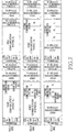
- FIG. 5 illustrates a first frame structure according to an exemplary embodiment of the present invention.
- the upper first frame structure can be modified to the lower one. If users decrease in number in the first communication system and increase in number in the second communication system, the first frame should be modified such that the first communication system area is reduced and the second communication area is increased. Therefore, part of a first communication system area 501 in the upper first frame structure is used as a DL superframe header 513 in the lower first frame structure. While not illustrated in FIG. 5 , the UL area can be modified, as well as the DL area.
- the MS acquires synchronization to the BS using a superframe reference signal delivered in the DL superframe header 513, receives a BCH carrying broadcasting messages, and then receives DL/UL TTIs 515, 517, 519 and 521.
- the BS generates a message including frame configuration information about the changed first frame structure and transmits it to the MS before the frame structure modification.
- the MS receives the BCH and the DL/UL TTIs 515, 517, 519 and 521 according to the frame configuration information without depending on the superframe reference signal or the blind-detected BCH position information.
- the MS does not need to depend on the superframe reference signal because reception of the superframe reference symbol designed for initial synchronization acquisition takes a considerable amount of time.
- the MS is burdened by having to process the superframe reference signal quickly.
- the blind detection of the BCH position information also imposes a constraint on the MS.
- the MS locates the BCH and the DL/UL TTIs based on the frame configuration information.
- the superframe reference symbol 249 precedes the BCH carrying the broadcasting messages 251, 253, 255, ... 257, followed by DL/UL TTIs.
- the positions of the BCH and DL/UL TTIs are known from the position information about the superframe reference symbol. Therefore, the MS should be able to compute t SF _ offset .
- the MS should be able to compute t SF_offset .
- the MS computes t SF_offset using information about the number of the DL TTIs set in the frame configuration information and locates the BCH and the DL/UL TTIs using t SF_offset in the above-described two cases, that is, in the presence of the superframe reference symbol 249 and the BCH in the superframe header 201 or 221 and in the presence of only the BCH in the superframe header 201 or 221.
- t SF_offset t superframe ⁇ ⁇ N ⁇ 2 DLTTI x t DTTI where t SF_offset is the interval between the superframe headers of the current and next superframes, i.e.
- t superframe is a superframe length in the second communication system
- ⁇ N2 DLTTI is the difference in a number between the DL TTIs of superframes F and F+1
- t DTTI is the length of a DL TTI
- FIG. 6 illustrates a modification of a first frame structure to a second frame structure according to an exemplary embodiment of the present invention.
- the BS transmits frame configuration information about the changed frame structure to the MS so that the MS obtains knowledge of the changed frame structure before the structure modification.
- the BCH and the TTIs cannot be located simply with information about the number of the DL TTIs, as done in equation (1).
- the BS should transmit t SF_offset or its equivalent information to the MS.
- T DLGAP t superframe ⁇ ⁇ N ⁇ 2 DLTTI x t DTTI - T DLGAP_delta
- t SF_offset is the interval between the superframe header 603 of superframe F and superframe header 615 of superframe F+1
- t superframe is the length of a superframe
- ⁇ N2 DLTTI is the difference in a number between the DL TTIs of superframes F and F+1
- t DTTI is the length of a DL TTI.
- t DLGAP_delta t DLGAP - ⁇ N2 DLTTI ⁇ t DTTI
- t DLGAP is the time difference between the preamble of the first communication system and the superframe reference signal or superframe header of the second communication system. If t DLGAP_delta is 0, which means that the fist communication system area still exists, equation (2) is equal to equation (1). Therefore, t SF_offset can be computed by equation (2) regardless of whether the displacement of the superframe reference signal or the superframe header is or is not an integer multiple of t DTTI .
- the BS can generate superframe offset information corresponding to t SF_offset based on the parameters of equation (2) and transmit the superframe offset information to the MS.
- the superframe offset information includes the following information.
- the BS can transmit the t SF_offset indicator together with t DLGAP , t DLGAP_delta and ⁇ N2 DLTTI , or only the t SF_offset indicator to the MS.
- the MS detects the preamble of the first communication system and the superframe reference signal or superframe header of the second communication system, computes the relative time difference between them, i.e. t DLGAP , and calculates t SF_offset , before the frame configuration information is changed.
- the MS can use equation (2) in calculating t SF_offset .
- the MS locates the superframe reference symbol, and the following BCH and DL/UL TTIs according to t SF_offset .
- the superframe header of the second communication system includes the BCH only, except for the superframe reference signal, the MS locates the superframe header, i.e. the BCH and the following DL/UL TTIs according to t SF_offset .
- the BS can additionally transmit a frame number indicating the generation time of t SF_offset to the MS.
- the BS can transmit the superframe offset information to the MS in the following manners.
- FIG. 6 The description of FIG. 6 is valid not only when the superframe reference signal is positioned in the first DL TTI of a frame as illustrated in FIG. 6 , but also when it is in the last DL TTI of the frame.
- the MS should search for a cell to camp on and acquire frame synchronization to the cell.
- FIG. 7 illustrates a frame structure for a communication system having a plurality of cells when it operates in the first mode according to an exemplary embodiment of the present invention.
- the communication system includes cells 900, 920 and 940 (Cell A, Cell B and Cell C) that can transmit TDD frames designed in various structures according to their DL-UL ratios.
- Cell A transmits a frame with a ratio between the DL areas of the first and second communication systems being 1:1 (a first-second DL ratio being 1:1)
- Cell B transmits a frame with a first-second DL ratio being 1:2
- Cell C transmits a frame with a first-second DL ratio being 1:3.
- DL superframe headers 901, 921 and 941 each including a superframe reference symbol for cell search and frame synchronization acquisition and broadcasting messages carrying frame configuration information are transmitted at different times in the different cells 900, 920 and 940.
- the MS should search all of Cell A 900, Cell B 920 and Cell C 940 to discover its serving cell.
- system DL overhead increases and the operational complexity of the MS also increases because of the DL superframe headers 901, 921 and 941 transmitted at different times.
- exemplary embodiments of the present invention propose three schemes for enabling the MS to efficiently search for a cell to camp on.
- One of the schemes is to configure the frames such that the cells transmit the superframe reference symbols of the superframe headers physically at the same time, for synchronization acquisition. Another is to configure the frames such that the cells transmit the superframe headers physically at the same time, for synchronization acquisition.
- the other scheme is that the MS detects the superframe header of the second communication system using the preamble signal of the first communication system.
- FIG. 8 illustrates frame structures including reference symbols transmitted at the same time according to an exemplary embodiment of the present invention.
- cells 1000, 1020, and 1040 (Cell A, Cell B and Cell C) transmit superframe reference symbols 1003, 1023, and 1043 at the same time.
- the MS can select its serving cell by one cell search and acquire frame synchronization to the serving cell.
- the superframe reference symbols 1003, 1023 and 1043 are transmitted at the ends of the DL subframes of the second communication system in the illustrated case of FIG. 8 , they can be transmitted in any part of the DL subframes of the second communication system as long as their transmissions are simultaneous.
- FIG. 9 illustrates frame structures including DL superframe headers transmitted at the same time according to an exemplary embodiment of the present invention.
- cells 1100, 1120 and 1140 (Cell A, Cell B and Cell C) transmit DL superframe headers 1101, 1121 and 1141 at the same time.
- the MS can select its serving cell by one cell search and acquire frame synchronization to the serving cell.
- the DL superframe headers 1101, 1121 and 1141 are transmitted at the ends of the DL subframes of the second communication system in the illustrated case of FIG. 9 , they can be transmitted in any part of the DL subframes of the second communication system as long as their transmissions are simultaneous.
- FIG. 10 is a flowchart illustrating an operation of an MS, when the second communication system includes a plurality of cells according to an exemplary embodiment of the present invention.
- the MS detects a preamble signal of the first communication system in step 1200 and searches for its serving cell using the preamble signal in step 1202.
- step 1204 the MS detects a DL superframe header of the second communication system from the cell. Then the MS acquires frame synchronization to the second communication system in step 1206.
- FIG. 11 is a block diagram of a transmitter of a BS according to an exemplary embodiment of the present invention.
- the BS transmitter includes a frame configuration information generator/controller 1301, a gap generator 1303, a TTG/RTG generator 1305, a superframe header generator 1307, a DL/UL TTI generator 1309, a frame generator for the first communication system 1311, and a combiner 1313.
- the frame configuration information generator/controller 1301 generates frame configuration information including t SF_offset , a superframe length, and a DL-UL ratio and controls the gap generator 1303, the TTG/RTG generator 1305, the superframe header generator 1307, the DL/UL TTI generator 1309, and the frame generator for the first communication system 1311. If the frame configuration information is transmitted on a BCH, in an in-band MAC message during a traffic DL/UL TTI, by overriding it on a preamble signal of the first communication system, or in a superframe reference signal of the second communication system, it can be generated in a generator corresponding to the transmission scheme for the frame configuration information.
- the gap generator 1303, the TTG/RTG generator 1305, the superframe header generator 1307, the DL/UL TTI generator 1309, and the frame generator for the first communication system 1311 generate elements for a frame of the second communication system under the control of the frame configuration information generator/controller 1301.
- the superframe header generator 1307 includes a superframe reference signal extractor. Therefore, the superframe header generator 1307 outputs a superframe header and can output a superframe reference signal extracted by the reference signal extractor.
- the combiner 1313 generates a first frame by combining the frame elements of the second/first communication system received from the gap generator 1303, the TTG/RTG generator 1305, the superframe header generator 1307, the DL/UL TTI generator 1309, and the frame generator for the first communication system 1311 and transmits the first frame to the MS.
- FIG. 12 is a block diagram of a receiver of an MS according to an exemplary embodiment of the present invention.
- the MS receiver includes a frame configuration information controller 1401, a separator 1403, a gap receiver 1405, a TTG/RTG receiver 1407, a superframe header receiver 1409, a DL/UL TTI receiver 1411, and a frame receiver for the first communication system 1413.
- the frame configuration information controller 1401 stores frame configuration information including t SF_offset , a superframe length, and a DL-UL ratio received from the BS transmitter and controls the separator 1403, the gap receiver 1405, the TTG/RTG receiver 1407, the superframe header receiver 1409, the DL/UL TTI receiver 1411, and the frame receiver for the first communication system 1413 based on the frame configuration information.
- the MS receives the frame configuration information through a receiver corresponding to the transmission scheme of the frame configuration information.
- the separator 1403 separates frame elements from the received signal under the control of the frame configuration information controller 1401 and outputs them to the gap receiver 1405, the TTG/RTG receiver 1407, the superframe header receiver 1409, the DL/UL TTI receiver 1411, and the frame receiver for the first communication system 1413.
- the separator 1403 determines whether the frame configuration information has been changed using t SF_offset received from the frame configuration information controller 1401. If the frame configuration information has been changed, the separator 1403 separates the frame elements according to the changed frame configuration information.
- the gap receiver 1405, the TTG/RTG receiver 1407, the superframe header receiver 1409, the DL/UL TTI receiver 1411, and the frame receiver for the first communication system 1413 receive the frame elements under the control of the frame configuration information controller 1401.
- a receiver corresponding to the transmission scheme of the frame configuration information which is one of transmission on a BCH, transmission in an in-band MAC message during a traffic DL/UL TTI, transmission in a preamble signal of the first communication system, and transmission in a superframe reference signal of the second communication system, receives the frame configuration information from and provides the frame configuration information to the frame configuration information controller 1401.
- FIG. 13 is a flowchart illustrating an operation for generating and transmitting a frame depending on whether a frame structure is changed in the BS transmitter according to an exemplary embodiment of the present invention.
- the BS determines whether a first frame structure for the first/second communication system is changed in superframe N in step 701.
- the first frame structure change can be a change in the position(s) of a superframe header, a BCH, or DL/UL TTIs. If the first frame structure is changed, the frame configuration information generator/controller 1301 proceeds to step 703 and otherwise, it jumps to step 705.
- the frame configuration information generator/controller 1301 In step 703, the frame configuration information generator/controller 1301 generates frame configuration information about the changed common frame structure and transmits it to the MS. To reduce overhead, the frame configuration information generator/controller 1301 transmits the frame configuration information on the BCH, in an in-band MAC message during a traffic DL/UL TTI, in a preamble signal of the first communication system, or in a superframe reference signal of the second communication system.
- step 705 the frame configuration information generator/controller 1301 determines whether the first frame structure is changed in a current superframe. If the first frame structure is changed, the frame configuration information generator/controller 1301 proceeds to step 707 and otherwise, it goes to step 709.
- step 709 the frame configuration information generator/controller 1301 generates a first frame according to current frame configuration information by controlling the gap generator 1303, the TTG/RTG generator 1305, the superframe header generator 1307, the DL/UL TTI generator 1309, and the frame generator 1311 for the first communication system and transmits the first frame to the MS. Then the procedure returns to step 701.
- step 707 the frame configuration information generator/controller 1301 changes the current frame configuration information according to the generated frame configuration information.
- step 711 the frame configuration information generator/controller 1301 generates a first frame based on the changed frame configuration information by controlling the gap generator 1303, the TTG/RTG generator 1305, the superframe header generator 1307, the DL/UL TTI generator 1309, and the frame generator 1311 for the first communication system and transmits the common frame to the MS. Then the procedure returns to step 701.
- FIG. 14 is a flowchart illustrating an operation for receiving a frame depending on whether a frame structure has been changed according to an exemplary embodiment of the present invention.
- the frame configuration information controller 1401 determines whether frame configuration information about a change in a common frame structure in superframe N has been received in step 801. Upon receipt of the frame configuration information, the frame configuration information controller 1401 proceeds to step 803 and otherwise, it jumps to step 805.
- step 803 the frame configuration information controller 1401 stores the received changed frame configuration information. Then the frame configuration information controller 1401 determines whether a first frame structure is changed in a current superframe. If the first frame structure is changed, the frame configuration information controller 1401 proceeds to step 807 and otherwise, it goes to step 809.
- the frame configuration information controller 1401 receives a first frame according to current frame configuration information by controlling the gap receiver 1405, the TTG/RTG receiver 1407, the superframe header receiver 1409, the DL/UL TTI receiver 1411, and the frame receiver 1413 for the first communication system and returns to step 801.
- step 807 the frame configuration information controller 1401 changes the current frame configuration information according to the stored changed frame configuration information and goes to step 811.
- the frame configuration information controller 1401 receives a first frame according to the changed frame configuration information by controlling the gap receiver 1405, the TTG/RTG receiver 1407, the superframe header receiver 1409, the DL/UL TTI receiver 1411, and the frame receiver 1413 for the first communication system.
- exemplary embodiments of the present invention advantageously allocates resources so that a first communication system can co-exist with a second communication system.
- first and second communication systems use only TDD frames, they may use Frequency Division Duplexing (FDD) frames.
- FDD Frequency Division Duplexing
Description
- The present invention relates to a communication system. More particularly, the present invention relates to a system and method for transmitting/receiving a signal in a Broadband Wireless Access (BWA) communication system.
- Communication systems are under development to provide a variety of services including broadcasting, multimedia images, and multimedia messages. Studies are being made to provide services with different Quality of Service (QoS) requirements to users in future-generation communication systems. In addition, the developmental work of the future-generation communication systems is underway to provide a data service at or above 100Mbps to fast moving users and at or above 1Gbps to slow moving users beyond voice and packet data communication services.
- Such a future-generation communication system is a mobile Internet system. The mobile Internet system is called Mobile Worldwide interoperability for Microwave Access (WiMAX) or Wireless Broadband (WiBro), and is compatible with Institute of Electrical and Electronics Engineers (IEEE) 802.16 communication systems:
- The Mobile WiMAX system is making its way to the marketplace and now a Mobile WiMAX evolution communication system is under study. The Mobile WiMAX evolution system aims to support mobility of up to 300km per hour, support variable bandwidths, and minimize overhead.
- If the Mobile WiMAX communication system and the Mobile WiMAX evolution communication system are implemented, they should co-exist. Accordingly, there exists a need for a technique for operating a system that can enable co-existence of the Mobile WiMAX communication system and the Mobile WiMAX evolution communication system and efficiently operating the Mobile WiMAX evolution communication system, for example, a specified signal transmission/reception technique for transmitting broadcast information and providing information about a transmission frame structure in the Mobile WiMAX evolution communication system.
-
WO-2007/031958-A2 discloses a method of spectrum management in dynamic spectrum access wireless systems. A plurality of MAC/PHY stacks is adapted to support wireless devices. A superframe structure includes a preamble and a superframe initialization header. - An aim of certain embodiments of the present invention is to address at least the above-mentioned problems and/or disadvantages and to provide at least the advantages described below. Accordingly, an aim of certain embodiments of the present invention is to provide a system and method for transmitting/receiving a signal in a communication system.
- Another aim of certain embodiments of the present invention is to provide a signal transmission/reception system and method for, when a frame structure is changed, providing information about the changed frame structure in a BWA communication system.
- A further aim of certain embodiments of the present invention is to provide a signal transmission/reception system and method in a wireless access communication system having a plurality of cells.
- In accordance with a first aspect of the present invention there is provided a method of transmitting a signal by a transmitter in a communication system, in which a first communication system and a second communication system being evolved from the first communication system coexist, using a superframe, the superframe including a first frame area for the first communication system and a second frame area for the second communication system, and the second frame area starting from a superframe header, the method comprising: determining whether a position of the superframe header in the superframe is to change; and if the position of the superframe header is to change, transmitting to a receiver information indicating that the position of the superframe header is to change; wherein the information includes an indicator indicating that the position of the superframe header is to change; and wherein the information is transmitted before the position of the superframe header is changed.
- In accordance with a second aspect of the present invention there is provided a method of receiving a signal by a receiver in a communication system, in which a first communication system and a second communication system being evolved from the first communication system coexist, using a superframe, the superframe including a first frame area for the first communication system and a second frame area for the second communication system, the second frame area starting from a superframe header, the method comprising: receiving from a transmitter information indicating that a position of the superframe header in the superframe is to change, if the position of the superframe header is to change; and receiving the superframe header at the changed position of the superframe header using the information; wherein the information includes an indicator indicating that the position of the superframe header is to change; and wherein the information is transmitted before the position of the superframe header is changed.
- Other aspects, advantages, and salient features of the invention will become apparent to those skilled in the art from the following detailed description, which, taken in conjunction with the annexed drawings, discloses exemplary embodiments of the invention.
- The above and other aspects, features and advantages of certain exemplary embodiments of the present invention will be more apparent from the following detailed description taken in conjunction with the accompanying drawings, in which:
-
FIG. 1 illustrates a frame structure for a first communication system according to an exemplary embodiment of the present invention; -
FIGs. 2A ,2B and2C illustrate a second frame structure and a structure of a superframe header according to an exemplary embodiment of the present invention; -
FIG. 3 illustrates a first frame structure for a second communication system according to an exemplary embodiment of the present invention; -
FIGs. 4A and4B illustrate a frame structure using a Transmit/receive Transition Gap/Receive/transmit Transition Gap (TTG/RTG) and a frame structure using a DownLink/UpLink (DL/UL) gap for the second communication system according to exemplary embodiments of the present invention; -
FIG. 5 illustrates a first frame structure according to an exemplary embodiment of the present invention; -
FIG. 6 illustrates a modification of a first frame structure to a second frame structure according to an exemplary embodiment of the present invention; -
FIG. 7 illustrates a frame structure for a communication system having a plurality of cells when it operates in a first mode according to an exemplary embodiment of the present invention; -
FIG. 8 illustrates frame structures including reference symbols transmitted at the same time according to an exemplary embodiment of the present invention; -
FIG. 9 illustrates frame structures including DownLink (DL) superframe headers transmitted at the same time according to an exemplary embodiment of the present invention; -
FIG. 10 is a flowchart illustrating an operation of a Mobile Station (MS) when the second communication system includes a plurality of cells according to an exemplary embodiment of the present invention; -
FIG. 11 is a block diagram of a transmitter of a Base Station (BS) according to an exemplary embodiment of the present invention; -
FIG. 12 is a block diagram of a receiver of a MS according to an exemplary embodiment of the present invention; -
FIG. 13 is a flowchart illustrating an operation for generating and transmitting a frame depending on whether a frame structure has been changed in a BS transmitter according to an exemplary embodiment of the present invention; and -
FIG. 14 is a flowchart illustrating an operation for receiving a frame depending on whether a frame structure has been changed according to an exemplary embodiment of the present invention. - Throughout the drawings, the same drawing reference numerals will be understood to refer to the same elements, features and structures.
- - The following description with reference to the accompanying drawings is provided to assist in a comprehensive understanding of exemplary embodiments of the invention as defined by the claims and their equivalents. It includes various specific details to assist in that understanding but these are to be regarded as merely exemplary. Accordingly, those of ordinary skill in the art will recognize that various changes and modifications of the embodiments described herein can be made without departing from the scope of the invention as defined by the appended claims. In addition, descriptions of well-known functions and constructions are omitted for clarity and conciseness.
- It is to be understood that the singular forms "a," "an," and "the" include plural referents unless the context clearly dictates otherwise. Thus, for example, reference to "a component surface" includes reference to one or more of such surfaces.
- Exemplary embodiments of the present invention provide frame structures for a communication system where a first communication system coexists with a second communication system that is different from the first communication system. The exemplary embodiments of the present invention also provide a method for indicating a frame offset when the first communication system is replaced by the second communication system. The first and second communication systems can be an IEEE 802.16e system and an IEEE 802.16m system, respectively. In other words, the first and second communication systems can be Mobile WiMAX and Mobile WiMAX evolution, respectively.
- While the exemplary embodiments of the present invention will be described in the context of the first communication system being an IEEE 802.16 communication system and the second communication system being a communication system advanced from the IEEE 802.16 communication system, the frame structures and the signal transmission/reception method of the present invention are also applicable to other communication systems, for example, Code Division Multiple Access (CDMA), Wideband Code Division Multiple Access (WCDMA), and Global System for Mobile Telecommunication (GSM) communication systems.
- A communication scheme used in the first communication system is referred to as "a first communication scheme" and a communication scheme used in the second communication system is referred to as "a second communication scheme". The second communication system supports first and second modes. Both the first and second communication schemes are available in the first mode and only the second communication scheme is available in the second mode. In accordance with exemplary embodiments of the present invention, a first frame structure refers to a frame structure for the first mode and a second frame structure refers to a frame structure for the second mode.
-
FIG. 1 illustrates a frame structure for the first communication system according to an exemplary embodiment of the present invention. - Referring to
FIG. 1 , a frame used in the first communication system includes aDL subframe 109 and an UpLink (UL)subframe 111. TheDL subframe 109 has apreamble 101, a Frame Control Header (FCH) 103 carrying information about the configurations of MAPs, a DL-MAP 105 carrying resource allocation information relating to theDL subframe 109, and a UL-MAP 107 carrying resource allocation information relating to theUL subframe 111. -
Frames t frame 119. The durations of the DL andUL subframes t DL_subframe 115 andt UL_subframe 117, respectively. A TTG oflength t TTG 121 is interposed between theDL subframe 109 and theUL subframe 111, and an RTG oflength T RTG 123 is interposed between theframes -
FIGs. 2A and2B illustrate a second frame structure according to an exemplary embodiment of the present invention. - Referring to
FIG. 2A , a second frame includes asuperframe 200 with a plurality offrames frames UL TTIs 203. The duration of thesuperframe 200 ist superframe 223 and theframe 205 ist frame 217 long. The lengths of theDL TTI 201 and theUL TTI 203 aret DTTI 213 andt UTTI 215, respectively. - A gap between a DL TTI and a UL TTI is a TTG of
length t TTG 219 and the gap between frames, such asframe length t RTG 221. The DL TTI and the UL TTI occupy predetermined time/frequency resources. For instance, one subframe may include six symbols, each symbol forming one TTI. - In the illustrated case of
FIG. 2A , as oneframe 205 includes oneDL TTI 201 and oneUL TTI 203, it has a Time Division Duplexing (TDD) frame structure with a 1:1 DL-UL ratio. On the other hand, as illustrated inFIG. 2B , a TDD frame structure with a 2:1 DL-UL ratio can be contemplated, in which oneframe 227 includes twoDL TTIs UL TTI 225, for use in the second communication system. -
Superframes DL superframe headers DL TTIs first frames DL superframe headers -
FIG. 2C illustrates a structure of DL superframeheaders - Referring to
FIG. 2C , each of theDL superframe headers superframe reference symbol 249 carrying a superframe reference signal for system synchronization andbroadcasting messages - A first-mode BS generates a frame and transmits it to an MS of the second communication system. The MS acquires synchronization by receiving the
superframe symbol 249 of thesuperframe header broadcasting messages -
FIG. 3 illustrates a first frame structure for the second communication system according to an exemplary embodiment of the present invention. - In accordance with an exemplary embodiment of the present invention, the second communication system supports the first communication system. In other words, a BS in the first/second communication system supports an MS in the first communication system. In this context, the frame structure illustrated in
FIG. 3 is proposed to enable communications in both the first and second communication schemes when the second communication system operates in the first mode. - The first frame structure is designed for mutual compatibility between the first and second communication systems, so that the superframe structure of the second frame used in the second communication system is incorporated into the frame structure used in the first communication system.
- From among many frame structures available when the second communication system operates in the second mode, a TDD frame structure with a 1:1 DL-UL ratio will be referred to as an example.
- Referring to
FIG. 3 , acurrent frame 301 is divided into a DL subframe and a UL subframe with a TTG in between and thecurrent frame 301 is distinguished from anext frame 303 by an RTG. - The DL subframe includes a
preamble 307, an FCH 309, a DL-MAP 311, a UL-MAP 313, a DL data burst area for the first communication system 315 (referred to as a first communication system area 315), and DL areas for the second communication system 321 (referred to as second communication system area 321). The second communication system area 321 includes a DL superframe header 317 and a DL data burstarea 319 for the second communication system 321. - The UL subframe includes a UL data burst area for the
first communication system 323 and a UL data burst area for the second communication system 325. - The DL superframe header 317 is TDTTI long and the UL data burst area for the second communication system 325 can be tUTTI long.
- The
next frame 303 also includes apreamble 327, an FCH 329, a DL-MAP 331, a UL-MAP 333, a firstcommunication system area 335, and secondcommunication system area 351 including DL data burstareas second communication systems - While the DL superframe header 317 is in the
first frame 301 in the illustrated case ofFIG. 3 , it may be positioned in any other frame, for example, in theframe 303. - Although the DL superframe header 317 may include all of a superframe reference symbol and broadcasting messages as stated before, it can include the broadcasting messages only. In the latter case, the MS acquires synchronization to the BS using a preamble for the first communication system and then locates a BCH position by blind detection. Many methods are available for the blind detection of the BCH position, which is beyond the scope of the present invention and thus will not be detailed herein.
- Hence, the following description is made in the context of a communication system designed to detect the BCH position by blind detection, and takes into account the case where the DL superframe header 317 includes all of the superframe reference symbol and the broadcasting messages and the case where the DL superframe header 317 includes only the broadcasting messages.
- If the first communication system is replaced by the second communication system, a frame structure dedicated to the second communication system is needed. Accordingly, a method for utilizing a TTG/RTG and a method for utilizing temporary non-transmission TTIs of the second communication system among DL/UL TTIs are needed, in order to modify a frame structure for use in the second communication system only.
-
FIG. 4A illustrates a frame structure using a TTG/RTG for the second communication system according to an exemplary embodiment of the present invention. - Referring to
FIG. 4A , frames serving only the second communication system still have super frame headers, DL data burst areas, and UL data burstareas 401 to 411 that are designed for the second communication system. Notably, anRTG 413 substitutes for DL areas designed for the first communication system, i.e. theareas 307 to 315 illustrated inFIG. 3 . In addition, UL areas for the first communication system, i.e. thearea 323 illustrated inFIG. 3 are changed to aTTG 415.RTGs -
FIG. 4B illustrates a frame structure using a DL/UL gap for the second communication system according to another exemplary embodiment of the present invention. - Referring to
FIG. 4B , as in the frame structure according to the first exemplary embodiment of the present invention, a frame according to the second exemplary embodiment of the present invention has a DL gap 431 and a UL gap 435 in the place of the DL (i.e. theareas 307 to 315 illustrated inFIG. 3 ) and UL areas (i.e. theareas 323 and 325 illustrated inFIG. 3 ) set for the first communication system. Since no signals are transmitted/received in the DL gap and the UL gap, no signal interference occurs between the first and second communication systems. DL gaps 439, 447 and 451 and UL gaps 443 and 455 are created in the same manner. -
FIG. 5 illustrates a first frame structure according to an exemplary embodiment of the present invention. - Referring to
FIG. 5 , the upper first frame structure can be modified to the lower one. If users decrease in number in the first communication system and increase in number in the second communication system, the first frame should be modified such that the first communication system area is reduced and the second communication area is increased. Therefore, part of a firstcommunication system area 501 in the upper first frame structure is used as aDL superframe header 513 in the lower first frame structure. While not illustrated inFIG. 5 , the UL area can be modified, as well as the DL area. - As described above, two cases can be considered to operate the frame. In one case where the
DL superframe header 513 includes a superframe reference symbol and broadcasting messages, the MS acquires synchronization to the BS using a superframe reference signal delivered in theDL superframe header 513, receives a BCH carrying broadcasting messages, and then receives DL/UL TTIs - In the other case where the
DL superframe header 513 includes only the broadcasting messages, the MS acquires synchronization to the BS using the preamble of the first communication system area, receives the BCH based on BCH position information that has been detected by blind detection, and then receives the DL/UL TTIs FIG. 5 , since the second communication system area becomes wide, the relative position of the superframe header is changed, which in turn changes the positions of the DL/UL TTIs. - Thus, to give prior knowledge of the changed configuration of the first frame to the MS, the BS generates a message including frame configuration information about the changed first frame structure and transmits it to the MS before the frame structure modification. The MS receives the BCH and the DL/
UL TTIs - The MS locates the BCH and the DL/UL TTIs based on the frame configuration information. In the
superframe header FIG. 2C , thesuperframe reference symbol 249 precedes the BCH carrying thebroadcasting messages superframe header - The MS computes tSF_offset using information about the number of the DL TTIs set in the frame configuration information and locates the BCH and the DL/UL TTIs using tSF_offset in the above-described two cases, that is, in the presence of the
superframe reference symbol 249 and the BCH in thesuperframe header superframe header - If the displacement of the superframe reference symbol (i.e. the superframe reference signal) or the displacement of the superframe header is an integer multiple of tDTTI, tSF_offset is computed by

where tSF_offset is the interval between the superframe headers of the current and next superframes, i.e. the interval between the superframe header 503 of superframe F and that 513 of superframe F+1, tsuperframe is a superframe length in the second communication system, ΔN2DLTTI is the difference in a number between the DL TTIs of superframes F and F+1, and tDTTI is the length of a DL TTI. -
FIG. 6 illustrates a modification of a first frame structure to a second frame structure according to an exemplary embodiment of the present invention. - Referring to
FIG. 6 , when the first frame structure is modified to the second frame structure, the relative position of the superframe reference signal or the superframe header is changed. Hence, the BS transmits frame configuration information about the changed frame structure to the MS so that the MS obtains knowledge of the changed frame structure before the structure modification. - If the displacement of the superframe reference signal or the superframe header is not an integer multiple of tDTTI, the BCH and the TTIs cannot be located simply with information about the number of the DL TTIs, as done in equation (1). In this case, the BS should transmit tSF_offset or its equivalent information to the MS.
- Regardless of whether the displacement of the superframe reference signal or the superframe header is or is not an integer multiple of TDTTI, tSF_offset can be computed by

- Thus, the BS can generate superframe offset information corresponding to tSF_offset based on the parameters of equation (2) and transmit the superframe offset information to the MS. The superframe offset information includes the following information.
- 1) tSF_offset
- 2) tDLGAP, the time difference between the preamble of the first communication system and the superframe reference signal or the superframe header of the second communication system.
- 3) ΔN2DLTTI and tDLGAP_delta (if tDLGAP_delta =0, equation (1)).
- 4) a tSF_offset indicator indicating generation of tSF_offset.
- The BS can transmit the tSF_offset indicator together with tDLGAP, tDLGAP_delta and ΔN2DLTTI, or only the tSF_offset indicator to the MS.
- In the latter case, the MS detects the preamble of the first communication system and the superframe reference signal or superframe header of the second communication system, computes the relative time difference between them, i.e. tDLGAP , and calculates tSF_offset, before the frame configuration information is changed. The MS can use equation (2) in calculating tSF_offset. When receiving the tSF_offset indicator, the MS locates the superframe reference symbol, and the following BCH and DL/UL TTIs according to tSF_offset. If the superframe header of the second communication system includes the BCH only, except for the superframe reference signal, the MS locates the superframe header, i.e. the BCH and the following DL/UL TTIs according to tSF_offset. In the mean time, the BS can additionally transmit a frame number indicating the generation time of tSF_offset to the MS.
- The BS can transmit the superframe offset information to the MS in the following manners.
- 1) on the BCH.
- 2) by an in-band Medium Access Control (MAC) message in a traffic DL TTI.
- 3) by overriding a signal corresponding to tSF_offset on the preamble of the first communication system (i.e. by overriding a physical signal corresponding to tSF_offset on a conventional preamble signal).
- 4) in the superframe reference signal of the communication system (i.e. superframe reference signals corresponding to tSF_offset values are defined and a superframe reference signal corresponding to a specific tSF_offset value is transmitted).
- The description of
FIG. 6 is valid not only when the superframe reference signal is positioned in the first DL TTI of a frame as illustrated inFIG. 6 , but also when it is in the last DL TTI of the frame. - If the second communication system has a plurality of cells, the MS should search for a cell to camp on and acquire frame synchronization to the cell.
-
FIG. 7 illustrates a frame structure for a communication system having a plurality of cells when it operates in the first mode according to an exemplary embodiment of the present invention. - Referring to
FIG. 7 , the communication system includescells DL superframe headers different cells - Therefore, the MS should search all of
Cell A 900,Cell B 920 andCell C 940 to discover its serving cell. In addition, during handover from the serving cell including a serving BS to another cell that will provide a better service than the serving cell, system DL overhead increases and the operational complexity of the MS also increases because of theDL superframe headers - In this context, exemplary embodiments of the present invention propose three schemes for enabling the MS to efficiently search for a cell to camp on.
- One of the schemes is to configure the frames such that the cells transmit the superframe reference symbols of the superframe headers physically at the same time, for synchronization acquisition. Another is to configure the frames such that the cells transmit the superframe headers physically at the same time, for synchronization acquisition. The other scheme is that the MS detects the superframe header of the second communication system using the preamble signal of the first communication system.
- With reference to
FIG. 8 , a description will first be made of the first scheme. -
FIG. 8 illustrates frame structures including reference symbols transmitted at the same time according to an exemplary embodiment of the present invention. - Referring to
FIG. 8 ,cells superframe reference symbols - While the
superframe reference symbols FIG. 8 , they can be transmitted in any part of the DL subframes of the second communication system as long as their transmissions are simultaneous. -
FIG. 9 illustrates frame structures including DL superframe headers transmitted at the same time according to an exemplary embodiment of the present invention. - Referring to
FIG. 9 ,cells DL superframe headers - While the
DL superframe headers FIG. 9 , they can be transmitted in any part of the DL subframes of the second communication system as long as their transmissions are simultaneous. -
FIG. 10 is a flowchart illustrating an operation of an MS, when the second communication system includes a plurality of cells according to an exemplary embodiment of the present invention. - Referring to
FIG. 10 , the MS detects a preamble signal of the first communication system instep 1200 and searches for its serving cell using the preamble signal instep 1202. - In
step 1204, the MS detects a DL superframe header of the second communication system from the cell. Then the MS acquires frame synchronization to the second communication system instep 1206. -
FIG. 11 is a block diagram of a transmitter of a BS according to an exemplary embodiment of the present invention. - Referring to
FIG. 11 , the BS transmitter includes a frame configuration information generator/controller 1301, agap generator 1303, a TTG/RTG generator 1305, asuperframe header generator 1307, a DL/UL TTI generator 1309, a frame generator for thefirst communication system 1311, and acombiner 1313. - The frame configuration information generator/
controller 1301 generates frame configuration information including tSF_offset, a superframe length, and a DL-UL ratio and controls thegap generator 1303, the TTG/RTG generator 1305, thesuperframe header generator 1307, the DL/UL TTI generator 1309, and the frame generator for thefirst communication system 1311. If the frame configuration information is transmitted on a BCH, in an in-band MAC message during a traffic DL/UL TTI, by overriding it on a preamble signal of the first communication system, or in a superframe reference signal of the second communication system, it can be generated in a generator corresponding to the transmission scheme for the frame configuration information. - The
gap generator 1303, the TTG/RTG generator 1305, thesuperframe header generator 1307, the DL/UL TTI generator 1309, and the frame generator for thefirst communication system 1311 generate elements for a frame of the second communication system under the control of the frame configuration information generator/controller 1301. Thesuperframe header generator 1307 includes a superframe reference signal extractor. Therefore, thesuperframe header generator 1307 outputs a superframe header and can output a superframe reference signal extracted by the reference signal extractor. - The
combiner 1313 generates a first frame by combining the frame elements of the second/first communication system received from thegap generator 1303, the TTG/RTG generator 1305, thesuperframe header generator 1307, the DL/UL TTI generator 1309, and the frame generator for thefirst communication system 1311 and transmits the first frame to the MS. -
FIG. 12 is a block diagram of a receiver of an MS according to an exemplary embodiment of the present invention. - Referring to
FIG. 12 , the MS receiver includes a frameconfiguration information controller 1401, aseparator 1403, agap receiver 1405, a TTG/RTG receiver 1407, asuperframe header receiver 1409, a DL/UL TTI receiver 1411, and a frame receiver for thefirst communication system 1413. - The frame
configuration information controller 1401 stores frame configuration information including tSF_offset, a superframe length, and a DL-UL ratio received from the BS transmitter and controls theseparator 1403, thegap receiver 1405, the TTG/RTG receiver 1407, thesuperframe header receiver 1409, the DL/UL TTI receiver 1411, and the frame receiver for thefirst communication system 1413 based on the frame configuration information. - If the BS transmitter transmits the frame configuration information on a BCH, in an in-band MAC message during a traffic DL/UL TTI, in a preamble signal of the first communication system, or in a superframe reference signal of the second communication system, the MS receives the frame configuration information through a receiver corresponding to the transmission scheme of the frame configuration information.
- The
separator 1403 separates frame elements from the received signal under the control of the frameconfiguration information controller 1401 and outputs them to thegap receiver 1405, the TTG/RTG receiver 1407, thesuperframe header receiver 1409, the DL/UL TTI receiver 1411, and the frame receiver for thefirst communication system 1413. Theseparator 1403 determines whether the frame configuration information has been changed using tSF_offset received from the frameconfiguration information controller 1401. If the frame configuration information has been changed, theseparator 1403 separates the frame elements according to the changed frame configuration information. - The
gap receiver 1405, the TTG/RTG receiver 1407, thesuperframe header receiver 1409, the DL/UL TTI receiver 1411, and the frame receiver for thefirst communication system 1413 receive the frame elements under the control of the frameconfiguration information controller 1401. - In addition; a receiver corresponding to the transmission scheme of the frame configuration information, which is one of transmission on a BCH, transmission in an in-band MAC message during a traffic DL/UL TTI, transmission in a preamble signal of the first communication system, and transmission in a superframe reference signal of the second communication system, receives the frame configuration information from and provides the frame configuration information to the frame
configuration information controller 1401. -
FIG. 13 is a flowchart illustrating an operation for generating and transmitting a frame depending on whether a frame structure is changed in the BS transmitter according to an exemplary embodiment of the present invention. - Referring to
FIG. 13 , the BS determines whether a first frame structure for the first/second communication system is changed in superframe N instep 701. The first frame structure change can be a change in the position(s) of a superframe header, a BCH, or DL/UL TTIs. If the first frame structure is changed, the frame configuration information generator/controller 1301 proceeds to step 703 and otherwise, it jumps to step 705. - In
step 703, the frame configuration information generator/controller 1301 generates frame configuration information about the changed common frame structure and transmits it to the MS. To reduce overhead, the frame configuration information generator/controller 1301 transmits the frame configuration information on the BCH, in an in-band MAC message during a traffic DL/UL TTI, in a preamble signal of the first communication system, or in a superframe reference signal of the second communication system. - In
step 705, the frame configuration information generator/controller 1301 determines whether the first frame structure is changed in a current superframe. If the first frame structure is changed, the frame configuration information generator/controller 1301 proceeds to step 707 and otherwise, it goes to step 709. - In
step 709, the frame configuration information generator/controller 1301 generates a first frame according to current frame configuration information by controlling thegap generator 1303, the TTG/RTG generator 1305, thesuperframe header generator 1307, the DL/UL TTI generator 1309, and theframe generator 1311 for the first communication system and transmits the first frame to the MS. Then the procedure returns to step 701. - In
step 707, the frame configuration information generator/controller 1301 changes the current frame configuration information according to the generated frame configuration information. - In
step 711, the frame configuration information generator/controller 1301 generates a first frame based on the changed frame configuration information by controlling thegap generator 1303, the TTG/RTG generator 1305, thesuperframe header generator 1307, the DL/UL TTI generator 1309, and theframe generator 1311 for the first communication system and transmits the common frame to the MS. Then the procedure returns to step 701. -
FIG. 14 is a flowchart illustrating an operation for receiving a frame depending on whether a frame structure has been changed according to an exemplary embodiment of the present invention. - Referring to
FIG. 14 , the frameconfiguration information controller 1401 determines whether frame configuration information about a change in a common frame structure in superframe N has been received instep 801. Upon receipt of the frame configuration information, the frameconfiguration information controller 1401 proceeds to step 803 and otherwise, it jumps to step 805. - In
step 803, the frameconfiguration information controller 1401 stores the received changed frame configuration information. Then the frameconfiguration information controller 1401 determines whether a first frame structure is changed in a current superframe. If the first frame structure is changed, the frameconfiguration information controller 1401 proceeds to step 807 and otherwise, it goes to step 809. - In
step 809, the frameconfiguration information controller 1401 receives a first frame according to current frame configuration information by controlling thegap receiver 1405, the TTG/RTG receiver 1407, thesuperframe header receiver 1409, the DL/UL TTI receiver 1411, and theframe receiver 1413 for the first communication system and returns to step 801. - In
step 807, the frameconfiguration information controller 1401 changes the current frame configuration information according to the stored changed frame configuration information and goes to step 811. - In
step 811, the frameconfiguration information controller 1401 receives a first frame according to the changed frame configuration information by controlling thegap receiver 1405, the TTG/RTG receiver 1407, thesuperframe header receiver 1409, the DL/UL TTI receiver 1411, and theframe receiver 1413 for the first communication system. - As is apparent from the above exemplary communication systems, exemplary embodiments of the present invention advantageously allocates resources so that a first communication system can co-exist with a second communication system.
- When frame structures for the first and second communication systems are modified, frame configuration information about the changed frame structures is provided. Therefore, a change in a frame structure can be coped with actively.
- While the invention has been shown and described with reference to certain exemplary embodiments thereof, they are merely exemplary applications. For example, while it has been described that the first and second communication systems use only TDD frames, they may use Frequency Division Duplexing (FDD) frames. Thus, it will be understood by those skilled in the art that various changes in form and details may be made therein without departing from the scope of the present invention as defined by the appended claims.
Claims (14)
- A method of transmitting a signal by a transmitter in a communication system, in which a first communication system and a second communication system coexist, using a superframe, the superframe including a first frame area (315) for the first communication system and a second frame area (321) for the second communication system, and the second frame area (321) starting from a superframe header (317), the method comprising:determining (701) whether a position of the superframe header (317) in the superframe is to change; andif the position of the superframe header (317) is to change, transmitting (703) to a receiver information indicating that the position of the superframe header (317) is to change;wherein the information indicates that the position of the superframe header (317) is to change; andwherein the information is transmitted (703) before the position of the superframe header (317) is changed.
- The method of claim 1, wherein the superframe header (317) includes at least one of a reference signal and a broadcasting message for the second communication system; and
wherein the position of the superframe header (317) is changed, if at least one of a position of a Broadcast Channel, BCH, and a position of DownLink/UpLink Transmission Time Intervals, DL/UL TTIs, is changed. - The method of claim 1, wherein the information includes at least one of a difference between a superframe duration before the position of the superframe header (317) is changed and a superframe duration after the position of the superframe header (317) is changed, a difference between a number of downlink or uplink Transmission Time Intervals, TTIs, before the position of the superframe header (317) is changed and a number of downlink or uplink TTIs after the position of the superframe header (317) is changed.
- The method of claim 1, wherein the superframe, after the position of the superframe header (317) is changed, is used for one of the first communication system and the second communication system.
- The method of claim 3, wherein the difference between the superframe duration before the position of the superframe header (317) is changed and the superframe duration after the position of the superframe header (317) is changed, tSF_offset , is calculated by the following equation:

where tsuperframe denotes the superframe duration before the position of the superframe header (317) is changed, ΔN2DLTTI denotes the difference between the number of downlink TTIs before the position of the superframe header (317) is changed and the number of downlink TTIs after the position of the superframe header (317) is changed, tDTTI denotes a length of a downlink TTI, TDLGAP_delta =TDLGAP-ΔN2DLTTI×tDTTI , TDLGAP denotes a time difference between a reference signal or the superframe header (317) before the position of the superframe header is changed and a reference signal or the superframe header (317) after the position of the superframe header (317) is changed. - The method of claim 3, wherein the difference between the superframe duration before the position of the superframe header (317) is changed and the superframe duration after the position of the superframe header (317) is changed, tSF_offset, is calculated by the following equation:

where tsuperframe denotes the superframe duration before the position of the superframe header (317) is changed, ΔN2DLTTI denotes the difference between the number of downlink TTIs before the position of the superframe header (317) is changed and the number of downlink TTIs after the position the superframe header (317) is changed, and tDTTI denotes the length of a downlink TTI. - A transmitter for transmitting a signal in a communication system, in which a first communication system and a second communication system coexist, the signal using a superframe, the superframe including a first frame area for the first communication system and a second frame area for the second communication system, and the second frame area starting from a superframe header (317), wherein the transmitter is adapted to perform the steps of the method described in claims 1 to 6.
- A method of receiving a signal by a receiver in a communication system, in which a first communication system and a second communication system coexist, using a superframe, the superframe including a first frame area for the first communication system and a second frame area for the second communication system, the second frame area starting from a superframe header (317), the method comprising:receiving (801) from a transmitter information indicating that a position of the superframe header (317) in the superframe is to change, if the position of the superframe header (317) is to change; andreceiving (811) the superframe header (317) at the changed position of the superframe header (317) using the information;wherein the information indicates that the position of the superframe header (317) is to change; andwherein the information is transmitted before the position of the superframe header (317) is changed.
- The method of claim 8, wherein the superframe header (317) includes at least one of a reference signal and a broadcasting message for the second communication system; and
wherein the position of the superframe header (317) is changed, if at least one of a position of a Broadcast Channel, BCH, and a position of DownLink/UpLink Transmission Time Intervals, DL/UL TTIs, is changed. - The method of claim 8, wherein the information includes at least one of a difference between a superframe duration before the position of the superframe header (317) is changed and a superframe duration after the position of the superframe header (317) is changed, a difference between a number of downlink or uplink Transmission Time Intervals, TTIs, before the position of the superframe header (317) is changed and a number of downlink or uplink TTIs after the position of the superframe header is changed.
- The method of claim 8, wherein the superframe, after the position of the superframe header (317) is changed, is used for one of the first communication system and the second communication system.
- The method of claim 10, wherein the difference between the superframe duration before the position of the superframe header (317) is changed and the superframe duration after the position of the superframe header (317) is changed, tSF_offset , is calculated by the following equation:

where tsuperframe denotes the superframe duration before the position of the superframe header (317) is changed, ΔN2DLTTI denotes the difference between the number of downlink TTIs before the position of the superframe header is changed and the number of downlink TTIs after the position of the superframe header (317) is changed, tDTTI denotes a length of a downlink TTI, TDLGAP_delta=TDLGAP-ΔN2DLTTI×tDTTI , TDLGAP denotes a time difference between a reference signal or the superframe header (317) before the position of the superframe header (317) is changed and a reference signal or the superframe header (317) after the position of the superframe header (317) is changed. - The method of claim 10, wherein the difference between the superframe duration before the position of the superframe header (317) is changed and the superframe duration after the position of the superframe header (317) is changed, tSF_offset , is calculated by the following equation:

where tsuperframe denotes the superframe duration before the position of the superframe header (317) is changed, ΔN2DLTTI denotes the difference between the number of downlink TTIs before the position of the superframe header (317) is changed and the number of downlink TTIs after the position of the superframe header (317) is changed, and tDTTI denotes the length of a downlink TTI. - A receiver for receiving a signal in a communication system, in which a first communication system and a second communication system coexist, the signal using a superframe, the superframe including a first frame area for the first communication system and a second frame area for the second communication system, wherein the receiver is adapted to perform the steps of the method described in claims 8 to 13.
Applications Claiming Priority (4)
| Application Number | Priority Date | Filing Date | Title |
|---|---|---|---|
| KR20070104770 | 2007-10-17 | ||
| KR20070105833 | 2007-10-19 | ||
| KR1020070122340A KR101347424B1 (en) | 2007-10-17 | 2007-11-28 | Method and apparatus for transmit/receive signal in a comunication system |
| PCT/KR2008/006157 WO2009051447A2 (en) | 2007-10-17 | 2008-10-17 | System and method for transmitting/receiving signal in a communication system |
Publications (3)
| Publication Number | Publication Date |
|---|---|
| EP2201736A2 EP2201736A2 (en) | 2010-06-30 |
| EP2201736A4 EP2201736A4 (en) | 2012-08-08 |
| EP2201736B1 true EP2201736B1 (en) | 2013-07-31 |
Family
ID=40763430
Family Applications (1)
| Application Number | Title | Priority Date | Filing Date |
|---|---|---|---|
| EP08839413.5A Active EP2201736B1 (en) | 2007-10-17 | 2008-10-17 | System and method for transmitting/receiving signal in a communication system |
Country Status (5)
| Country | Link |
|---|---|
| US (1) | US7876734B2 (en) |
| EP (1) | EP2201736B1 (en) |
| KR (1) | KR101347424B1 (en) |
| CN (1) | CN101828370B (en) |
| WO (1) | WO2009051447A2 (en) |
Families Citing this family (15)
| Publication number | Priority date | Publication date | Assignee | Title |
|---|---|---|---|---|
| US8189626B2 (en) * | 2007-09-21 | 2012-05-29 | Future Wei Technologies, Inc. | System and method for multicast and broadcast synchronization in wireless access systems |
| JP5136085B2 (en) * | 2008-01-25 | 2013-02-06 | 富士通株式会社 | Reception device, mobile terminal device, and synchronization timing detection method |
| US8310987B2 (en) * | 2008-07-03 | 2012-11-13 | Samsung Electronics Co., Ltd. | Apparatus and method for notifying change of system control information in a broadband wireless communication system |
| US8804658B2 (en) * | 2008-10-22 | 2014-08-12 | Mediatek Inc. | Method and apparatus for handover between IEEE 802.16e and 802.16m systems |
| EP2392183A1 (en) * | 2009-01-27 | 2011-12-07 | Nokia Corp. | Method and apparatus for dynamically modifying a transmission frame |
| KR20100091887A (en) * | 2009-02-10 | 2010-08-19 | 엘지전자 주식회사 | Method and apparatus of updating for system information in a broadband wireless communication system |
| US8326309B2 (en) * | 2009-03-06 | 2012-12-04 | Bae Systems Information And Electronic Systems Integration Inc. | Resource allocation in co-existence mode |
| US8374139B2 (en) * | 2009-03-27 | 2013-02-12 | Mediatek Inc. | Low latency synchronization scheme for wireless OFDMA systems |
| KR20130028397A (en) | 2011-09-09 | 2013-03-19 | 삼성전자주식회사 | Apparatus and method for synchronizing and obtaining system information in wireless communication system |
| JP2013110677A (en) * | 2011-11-24 | 2013-06-06 | Mega Chips Corp | Communication system and communication device |
| US10219292B2 (en) | 2014-10-24 | 2019-02-26 | Qualcomm Incorporated | Flexible multiplexing and feedback for variable transmission time intervals |
| US10027462B2 (en) * | 2014-10-31 | 2018-07-17 | Qualcomm Incorporated | Unified frame structure |
| WO2016171765A1 (en) * | 2015-04-22 | 2016-10-27 | Intel IP Corporation | Transmission designs for radio access technologies |
| EP3346773A4 (en) * | 2015-09-01 | 2019-05-01 | NTT DoCoMo, Inc. | User terminal, wireless base station, and wireless communication method |
| WO2017099462A1 (en) * | 2015-12-07 | 2017-06-15 | 엘지전자 주식회사 | Uplink channel transmission method and user equipment, and uplink channel reception method and base station |
Family Cites Families (12)
| Publication number | Priority date | Publication date | Assignee | Title |
|---|---|---|---|---|
| US596637A (en) * | 1898-01-04 | store | ||
| US627212A (en) * | 1899-06-20 | Perpetual calendar | ||
| US5966373A (en) * | 1997-12-10 | 1999-10-12 | L-3 Communications Corporation | Waveform and frame structure for a fixed wireless loop synchronous CDMA communications system |
| US6272128B1 (en) * | 1998-06-16 | 2001-08-07 | Mci Communications Corporation | Method and system for emulating a T1 link over an ATM network |
| US7463600B2 (en) * | 2000-01-20 | 2008-12-09 | Nortel Networks Limited | Frame structure for variable rate wireless channels transmitting high speed data |
| US6993009B2 (en) * | 2000-03-10 | 2006-01-31 | Hughes Electronics Corporation | Method and apparatus for deriving uplink timing from asynchronous traffic across multiple transport streams |
| US7006464B1 (en) * | 2000-11-17 | 2006-02-28 | Lucent Technologies Inc. | Downlink and uplink channel structures for downlink shared channel system |
| KR100561393B1 (en) * | 2002-11-30 | 2006-03-16 | 삼성전자주식회사 | Media access control method in the wireless network and apparatus thereof |
| SE0300443D0 (en) * | 2003-02-17 | 2003-02-17 | Ericsson Telefon Ab L M | Method and system of channel adaptation |
| JP4005974B2 (en) * | 2004-01-09 | 2007-11-14 | 株式会社東芝 | COMMUNICATION DEVICE, COMMUNICATION METHOD, AND COMMUNICATION SYSTEM |
| CN1951070A (en) * | 2004-05-13 | 2007-04-18 | 皇家飞利浦电子股份有限公司 | Multiple receiver aggregation(MRA) with different data rates for ieee 802.11n |
| JP5247450B2 (en) * | 2005-09-16 | 2013-07-24 | コーニンクレッカ フィリップス エレクトロニクス エヌ ヴィ | Spectrum management in dynamic spectrum access radio systems |
-
2007
- 2007-11-28 KR KR1020070122340A patent/KR101347424B1/en active IP Right Grant
-
2008
- 2008-10-16 US US12/253,186 patent/US7876734B2/en active Active
- 2008-10-17 CN CN2008801123069A patent/CN101828370B/en not_active Expired - Fee Related
- 2008-10-17 EP EP08839413.5A patent/EP2201736B1/en active Active
- 2008-10-17 WO PCT/KR2008/006157 patent/WO2009051447A2/en active Application Filing
Also Published As
| Publication number | Publication date |
|---|---|
| WO2009051447A3 (en) | 2009-07-16 |
| CN101828370A (en) | 2010-09-08 |
| WO2009051447A2 (en) | 2009-04-23 |
| EP2201736A4 (en) | 2012-08-08 |
| KR20090039572A (en) | 2009-04-22 |
| EP2201736A2 (en) | 2010-06-30 |
| KR101347424B1 (en) | 2014-01-07 |
| US7876734B2 (en) | 2011-01-25 |
| US20090103569A1 (en) | 2009-04-23 |
| CN101828370B (en) | 2013-02-06 |
Similar Documents
| Publication | Publication Date | Title |
|---|---|---|
| EP2201736B1 (en) | System and method for transmitting/receiving signal in a communication system | |
| US11032835B2 (en) | Method and apparatus for scheduling in a wireless communication system | |
| US7885214B2 (en) | Device, system, and method for partitioning and framing communication signals in broadband wireless access networks | |
| JP6707188B2 (en) | Method and apparatus for transmitting/receiving PSCCH and PSSCH of terminal in wireless communication system | |
| US9219581B2 (en) | Base station and method for configuring sub-frames for relay-node operations | |
| US8644270B2 (en) | Method and system for configuring a frame in a communication system | |
| US8315330B2 (en) | Method of transmitting data in wireless communication system | |
| US20190268205A1 (en) | Method for obtaining information about cyclic prefix in wireless communication system and device for same | |
| US8160101B2 (en) | Method for communicating data between mobile station and base station, and mobile communication terminal thereof | |
| CN112887071A (en) | Transmission of system information for low cost user equipment | |
| US9237554B2 (en) | Method for allocating control information in wireless communication system | |
| US20110243107A1 (en) | Structure for OTA ENB-ENB Communication | |
| US20180077703A1 (en) | Data transmission method | |
| US20120147793A1 (en) | System and Method for the Coexistence of Multiple Communications Systems | |
| KR20180057463A (en) | Method and apparatus for adjusting bandwidth of a terminal | |
| JP5448221B2 (en) | Frame composition apparatus and method in frequency division multiplexing radio communication system | |
| JP2010130186A (en) | Base station and method of arranging sub burst region in the same |
Legal Events
| Date | Code | Title | Description |
|---|---|---|---|
| PUAI | Public reference made under article 153(3) epc to a published international application that has entered the european phase |
Free format text: ORIGINAL CODE: 0009012 |
|
| 17P | Request for examination filed |
Effective date: 20100416 |
|
| AK | Designated contracting states |
Kind code of ref document: A2 Designated state(s): AT BE BG CH CY CZ DE DK EE ES FI FR GB GR HR HU IE IS IT LI LT LU LV MC MT NL NO PL PT RO SE SI SK TR |
|
| AX | Request for extension of the european patent |
Extension state: AL BA MK RS |
|
| A4 | Supplementary search report drawn up and despatched |
Effective date: 20120710 |
|
| DAX | Request for extension of the european patent (deleted) | ||
| RIC1 | Information provided on ipc code assigned before grant |
Ipc: H04L 27/28 20060101AFI20120704BHEP Ipc: H04L 27/26 20060101ALI20120704BHEP |
|
| RAP1 | Party data changed (applicant data changed or rights of an application transferred) |
Owner name: SAMSUNG ELECTRONICS CO., LTD. |
|
| REG | Reference to a national code |
Ref country code: DE Ref legal event code: R079 Ref document number: 602008026485 Country of ref document: DE Free format text: PREVIOUS MAIN CLASS: H04L0027280000 Ipc: H04L0027260000 |
|
| GRAP | Despatch of communication of intention to grant a patent |
Free format text: ORIGINAL CODE: EPIDOSNIGR1 |
|
| RIC1 | Information provided on ipc code assigned before grant |
Ipc: H04L 27/26 20060101AFI20130207BHEP |
|
| GRAS | Grant fee paid |
Free format text: ORIGINAL CODE: EPIDOSNIGR3 |
|
| GRAA | (expected) grant |
Free format text: ORIGINAL CODE: 0009210 |
|
| AK | Designated contracting states |
Kind code of ref document: B1 Designated state(s): AT BE BG CH CY CZ DE DK EE ES FI FR GB GR HR HU IE IS IT LI LT LU LV MC MT NL NO PL PT RO SE SI SK TR |
|
| REG | Reference to a national code |
Ref country code: GB Ref legal event code: FG4D Ref country code: CH Ref legal event code: EP |
|
| REG | Reference to a national code |
Ref country code: AT Ref legal event code: REF Ref document number: 625203 Country of ref document: AT Kind code of ref document: T Effective date: 20130815 |
|
| REG | Reference to a national code |
Ref country code: IE Ref legal event code: FG4D |
|
| REG | Reference to a national code |
Ref country code: DE Ref legal event code: R096 Ref document number: 602008026485 Country of ref document: DE Effective date: 20130926 |
|
| REG | Reference to a national code |
Ref country code: AT Ref legal event code: MK05 Ref document number: 625203 Country of ref document: AT Kind code of ref document: T Effective date: 20130731 |
|
| REG | Reference to a national code |
Ref country code: NL Ref legal event code: VDEP Effective date: 20130731 |
|
| REG | Reference to a national code |
Ref country code: LT Ref legal event code: MG4D |
|
| PG25 | Lapsed in a contracting state [announced via postgrant information from national office to epo] |
Ref country code: SE Free format text: LAPSE BECAUSE OF FAILURE TO SUBMIT A TRANSLATION OF THE DESCRIPTION OR TO PAY THE FEE WITHIN THE PRESCRIBED TIME-LIMIT Effective date: 20130731 Ref country code: CY Free format text: LAPSE BECAUSE OF FAILURE TO SUBMIT A TRANSLATION OF THE DESCRIPTION OR TO PAY THE FEE WITHIN THE PRESCRIBED TIME-LIMIT Effective date: 20130828 Ref country code: HR Free format text: LAPSE BECAUSE OF FAILURE TO SUBMIT A TRANSLATION OF THE DESCRIPTION OR TO PAY THE FEE WITHIN THE PRESCRIBED TIME-LIMIT Effective date: 20130731 Ref country code: AT Free format text: LAPSE BECAUSE OF FAILURE TO SUBMIT A TRANSLATION OF THE DESCRIPTION OR TO PAY THE FEE WITHIN THE PRESCRIBED TIME-LIMIT Effective date: 20130731 Ref country code: LT Free format text: LAPSE BECAUSE OF FAILURE TO SUBMIT A TRANSLATION OF THE DESCRIPTION OR TO PAY THE FEE WITHIN THE PRESCRIBED TIME-LIMIT Effective date: 20130731 Ref country code: BE Free format text: LAPSE BECAUSE OF FAILURE TO SUBMIT A TRANSLATION OF THE DESCRIPTION OR TO PAY THE FEE WITHIN THE PRESCRIBED TIME-LIMIT Effective date: 20130731 Ref country code: IS Free format text: LAPSE BECAUSE OF FAILURE TO SUBMIT A TRANSLATION OF THE DESCRIPTION OR TO PAY THE FEE WITHIN THE PRESCRIBED TIME-LIMIT Effective date: 20131130 Ref country code: PT Free format text: LAPSE BECAUSE OF FAILURE TO SUBMIT A TRANSLATION OF THE DESCRIPTION OR TO PAY THE FEE WITHIN THE PRESCRIBED TIME-LIMIT Effective date: 20131202 Ref country code: NO Free format text: LAPSE BECAUSE OF FAILURE TO SUBMIT A TRANSLATION OF THE DESCRIPTION OR TO PAY THE FEE WITHIN THE PRESCRIBED TIME-LIMIT Effective date: 20131031 |
|
| PG25 | Lapsed in a contracting state [announced via postgrant information from national office to epo] |
Ref country code: SI Free format text: LAPSE BECAUSE OF FAILURE TO SUBMIT A TRANSLATION OF THE DESCRIPTION OR TO PAY THE FEE WITHIN THE PRESCRIBED TIME-LIMIT Effective date: 20130731 Ref country code: PL Free format text: LAPSE BECAUSE OF FAILURE TO SUBMIT A TRANSLATION OF THE DESCRIPTION OR TO PAY THE FEE WITHIN THE PRESCRIBED TIME-LIMIT Effective date: 20130731 Ref country code: GR Free format text: LAPSE BECAUSE OF FAILURE TO SUBMIT A TRANSLATION OF THE DESCRIPTION OR TO PAY THE FEE WITHIN THE PRESCRIBED TIME-LIMIT Effective date: 20131101 Ref country code: LV Free format text: LAPSE BECAUSE OF FAILURE TO SUBMIT A TRANSLATION OF THE DESCRIPTION OR TO PAY THE FEE WITHIN THE PRESCRIBED TIME-LIMIT Effective date: 20130731 Ref country code: NL Free format text: LAPSE BECAUSE OF FAILURE TO SUBMIT A TRANSLATION OF THE DESCRIPTION OR TO PAY THE FEE WITHIN THE PRESCRIBED TIME-LIMIT Effective date: 20130731 Ref country code: FI Free format text: LAPSE BECAUSE OF FAILURE TO SUBMIT A TRANSLATION OF THE DESCRIPTION OR TO PAY THE FEE WITHIN THE PRESCRIBED TIME-LIMIT Effective date: 20130731 |
|
| PG25 | Lapsed in a contracting state [announced via postgrant information from national office to epo] |
Ref country code: CY Free format text: LAPSE BECAUSE OF FAILURE TO SUBMIT A TRANSLATION OF THE DESCRIPTION OR TO PAY THE FEE WITHIN THE PRESCRIBED TIME-LIMIT Effective date: 20130731 |
|
| PG25 | Lapsed in a contracting state [announced via postgrant information from national office to epo] |
Ref country code: CZ Free format text: LAPSE BECAUSE OF FAILURE TO SUBMIT A TRANSLATION OF THE DESCRIPTION OR TO PAY THE FEE WITHIN THE PRESCRIBED TIME-LIMIT Effective date: 20130731 Ref country code: SK Free format text: LAPSE BECAUSE OF FAILURE TO SUBMIT A TRANSLATION OF THE DESCRIPTION OR TO PAY THE FEE WITHIN THE PRESCRIBED TIME-LIMIT Effective date: 20130731 Ref country code: DK Free format text: LAPSE BECAUSE OF FAILURE TO SUBMIT A TRANSLATION OF THE DESCRIPTION OR TO PAY THE FEE WITHIN THE PRESCRIBED TIME-LIMIT Effective date: 20130731 Ref country code: EE Free format text: LAPSE BECAUSE OF FAILURE TO SUBMIT A TRANSLATION OF THE DESCRIPTION OR TO PAY THE FEE WITHIN THE PRESCRIBED TIME-LIMIT Effective date: 20130731 Ref country code: RO Free format text: LAPSE BECAUSE OF FAILURE TO SUBMIT A TRANSLATION OF THE DESCRIPTION OR TO PAY THE FEE WITHIN THE PRESCRIBED TIME-LIMIT Effective date: 20130731 |
|
| PG25 | Lapsed in a contracting state [announced via postgrant information from national office to epo] |
Ref country code: MC Free format text: LAPSE BECAUSE OF FAILURE TO SUBMIT A TRANSLATION OF THE DESCRIPTION OR TO PAY THE FEE WITHIN THE PRESCRIBED TIME-LIMIT Effective date: 20130731 Ref country code: ES Free format text: LAPSE BECAUSE OF FAILURE TO SUBMIT A TRANSLATION OF THE DESCRIPTION OR TO PAY THE FEE WITHIN THE PRESCRIBED TIME-LIMIT Effective date: 20130731 |
|
| REG | Reference to a national code |
Ref country code: CH Ref legal event code: PL |
|
| PLBE | No opposition filed within time limit |
Free format text: ORIGINAL CODE: 0009261 |
|
| STAA | Information on the status of an ep patent application or granted ep patent |
Free format text: STATUS: NO OPPOSITION FILED WITHIN TIME LIMIT |
|
| 26N | No opposition filed |
Effective date: 20140502 |
|
| REG | Reference to a national code |
Ref country code: IE Ref legal event code: MM4A |
|
| PG25 | Lapsed in a contracting state [announced via postgrant information from national office to epo] |
Ref country code: LI Free format text: LAPSE BECAUSE OF NON-PAYMENT OF DUE FEES Effective date: 20131031 Ref country code: CH Free format text: LAPSE BECAUSE OF NON-PAYMENT OF DUE FEES Effective date: 20131031 |
|
| REG | Reference to a national code |
Ref country code: DE Ref legal event code: R097 Ref document number: 602008026485 Country of ref document: DE Effective date: 20140502 |
|
| PG25 | Lapsed in a contracting state [announced via postgrant information from national office to epo] |
Ref country code: IE Free format text: LAPSE BECAUSE OF NON-PAYMENT OF DUE FEES Effective date: 20131017 |
|
| PG25 | Lapsed in a contracting state [announced via postgrant information from national office to epo] |
Ref country code: TR Free format text: LAPSE BECAUSE OF FAILURE TO SUBMIT A TRANSLATION OF THE DESCRIPTION OR TO PAY THE FEE WITHIN THE PRESCRIBED TIME-LIMIT Effective date: 20130731 |
|
| PG25 | Lapsed in a contracting state [announced via postgrant information from national office to epo] |
Ref country code: BG Free format text: LAPSE BECAUSE OF FAILURE TO SUBMIT A TRANSLATION OF THE DESCRIPTION OR TO PAY THE FEE WITHIN THE PRESCRIBED TIME-LIMIT Effective date: 20130731 Ref country code: HU Free format text: LAPSE BECAUSE OF FAILURE TO SUBMIT A TRANSLATION OF THE DESCRIPTION OR TO PAY THE FEE WITHIN THE PRESCRIBED TIME-LIMIT; INVALID AB INITIO Effective date: 20081017 Ref country code: LU Free format text: LAPSE BECAUSE OF NON-PAYMENT OF DUE FEES Effective date: 20131017 |
|
| PG25 | Lapsed in a contracting state [announced via postgrant information from national office to epo] |
Ref country code: MT Free format text: LAPSE BECAUSE OF FAILURE TO SUBMIT A TRANSLATION OF THE DESCRIPTION OR TO PAY THE FEE WITHIN THE PRESCRIBED TIME-LIMIT Effective date: 20130731 |
|
| REG | Reference to a national code |
Ref country code: FR Ref legal event code: PLFP Year of fee payment: 9 |
|
| REG | Reference to a national code |
Ref country code: FR Ref legal event code: PLFP Year of fee payment: 10 |
|
| REG | Reference to a national code |
Ref country code: FR Ref legal event code: PLFP Year of fee payment: 11 |
|
| PGFP | Annual fee paid to national office [announced via postgrant information from national office to epo] |
Ref country code: IT Payment date: 20191015 Year of fee payment: 12 |
|
| PG25 | Lapsed in a contracting state [announced via postgrant information from national office to epo] |
Ref country code: IT Free format text: LAPSE BECAUSE OF NON-PAYMENT OF DUE FEES Effective date: 20201017 |
|
| PGFP | Annual fee paid to national office [announced via postgrant information from national office to epo] |
Ref country code: GB Payment date: 20220920 Year of fee payment: 15 |
|
| PGFP | Annual fee paid to national office [announced via postgrant information from national office to epo] |
Ref country code: FR Payment date: 20220920 Year of fee payment: 15 |
|
| PGFP | Annual fee paid to national office [announced via postgrant information from national office to epo] |
Ref country code: DE Payment date: 20220621 Year of fee payment: 15 |