EP2065997A1 - Battery charger and method - Google Patents
Battery charger and method Download PDFInfo
- Publication number
- EP2065997A1 EP2065997A1 EP07121927A EP07121927A EP2065997A1 EP 2065997 A1 EP2065997 A1 EP 2065997A1 EP 07121927 A EP07121927 A EP 07121927A EP 07121927 A EP07121927 A EP 07121927A EP 2065997 A1 EP2065997 A1 EP 2065997A1
- Authority
- EP
- European Patent Office
- Prior art keywords
- battery
- rated
- charging
- current
- voltage
- Prior art date
- Legal status (The legal status is an assumption and is not a legal conclusion. Google has not performed a legal analysis and makes no representation as to the accuracy of the status listed.)
- Granted
Links
Images


Classifications
-
- H—ELECTRICITY
- H02—GENERATION; CONVERSION OR DISTRIBUTION OF ELECTRIC POWER
- H02J—CIRCUIT ARRANGEMENTS OR SYSTEMS FOR SUPPLYING OR DISTRIBUTING ELECTRIC POWER; SYSTEMS FOR STORING ELECTRIC ENERGY
- H02J7/00—Circuit arrangements for charging or depolarising batteries or for supplying loads from batteries
- H02J7/0029—Circuit arrangements for charging or depolarising batteries or for supplying loads from batteries with safety or protection devices or circuits
- H02J7/00308—Overvoltage protection
-
- H—ELECTRICITY
- H02—GENERATION; CONVERSION OR DISTRIBUTION OF ELECTRIC POWER
- H02J—CIRCUIT ARRANGEMENTS OR SYSTEMS FOR SUPPLYING OR DISTRIBUTING ELECTRIC POWER; SYSTEMS FOR STORING ELECTRIC ENERGY
- H02J7/00—Circuit arrangements for charging or depolarising batteries or for supplying loads from batteries
- H02J7/007—Regulation of charging or discharging current or voltage
- H02J7/00711—Regulation of charging or discharging current or voltage with introduction of pulses during the charging process
-
- H—ELECTRICITY
- H02—GENERATION; CONVERSION OR DISTRIBUTION OF ELECTRIC POWER
- H02J—CIRCUIT ARRANGEMENTS OR SYSTEMS FOR SUPPLYING OR DISTRIBUTING ELECTRIC POWER; SYSTEMS FOR STORING ELECTRIC ENERGY
- H02J7/00—Circuit arrangements for charging or depolarising batteries or for supplying loads from batteries
- H02J7/007—Regulation of charging or discharging current or voltage
- H02J7/007188—Regulation of charging or discharging current or voltage the charge cycle being controlled or terminated in response to non-electric parameters
- H02J7/007192—Regulation of charging or discharging current or voltage the charge cycle being controlled or terminated in response to non-electric parameters in response to temperature
-
- H—ELECTRICITY
- H02—GENERATION; CONVERSION OR DISTRIBUTION OF ELECTRIC POWER
- H02J—CIRCUIT ARRANGEMENTS OR SYSTEMS FOR SUPPLYING OR DISTRIBUTING ELECTRIC POWER; SYSTEMS FOR STORING ELECTRIC ENERGY
- H02J7/00—Circuit arrangements for charging or depolarising batteries or for supplying loads from batteries
- H02J7/02—Circuit arrangements for charging or depolarising batteries or for supplying loads from batteries for charging batteries from ac mains by converters
- H02J7/04—Regulation of charging current or voltage
-
- H—ELECTRICITY
- H02—GENERATION; CONVERSION OR DISTRIBUTION OF ELECTRIC POWER
- H02J—CIRCUIT ARRANGEMENTS OR SYSTEMS FOR SUPPLYING OR DISTRIBUTING ELECTRIC POWER; SYSTEMS FOR STORING ELECTRIC ENERGY
- H02J7/00—Circuit arrangements for charging or depolarising batteries or for supplying loads from batteries
- H02J7/0029—Circuit arrangements for charging or depolarising batteries or for supplying loads from batteries with safety or protection devices or circuits
- H02J7/00302—Overcharge protection
Definitions
- the present invention relates to battery charging.
- this invention relates to a battery charging system and method suitable for use in standby applications.
- float charging One technique which is commonly used for charging Valve Regulated Lead Acid (VRLA) batteries, which are typically used in standby applications such as emergency systems, is known as float charging.
- VRLA Valve Regulated Lead Acid
- float charging it has been found that there are a number of drawbacks associated with float charging. These include the fact that the float charging regime overcharges the battery, and also causes excessive temperatures of the battery cells, which in turn degrades the chemical composition of the electrolyte in the battery, so as to shorten the battery life.
- a more efficient battery charging principle for standby VRLA batteries involves the use of what is known as the Intermittent Charge Control (ICC) principle, as described in reference M Bhatt, W G Hurley, W H Wölfle, "A New Approach to Intermittent Charging of Valve-Regulated Lead-Acid Batteries in Standby Applications", IEEE Transactions on Industrial Electronics, vol. 52, no. 5, pp. 1337-1342, October 2005 .
- ICC Intermittent Charge Control
- the ICC principle consists of four distinct operating modes, as shown in Figure 1 .
- Mode 1 a battery is charged with a charge current of 0.1 C rated A, where C rated is the rated battery capacity in Ah.
- SOC state of charge
- Mode 2 the battery is kept at open circuit to reduce the battery internal resistances built up in Mode 1, and provide more voltage head room for Mode 3.
- the battery voltage drops below a lower threshold voltage ( V lt )
- the operating mode changes from Mode 2 to Mode 3.
- Mode 3 the battery is charged with pulsed-currents with a peak current value of 0.05 C rated A, a period of 30 seconds and a current duty cycle (D) of 33.3%.
- Mode 3 The purpose of Mode 3 is to charge the battery to full SOC.
- the operating mode proceeds to Mode 4.
- Mode 4 the battery is fully charged and it is kept at open circuit.
- the battery voltage drops due to self-discharging in Mode 4.
- V r a restart charge voltage threshold
- the advantage of the ICC principle is that this charging regime prevents the battery from overcharging, while at the same time keeping the battery at high SOC to prevent sulfation.
- reaction rate in the electrolyte doubles for every 10°C increase in temperature. This in turn causes corrosion at the positive grid, and increases water loss and generates extra heat, which could lead to thermal runaway.
- the temperature compensated battery charger adjusts the float charging voltage based on the sensed ambient temperature or battery temperature. When the temperature increases, the charging voltage is accordingly decreased.
- a method for compensating for temperature effects in a pulsed battery-charging scheme with an average charging current less than the root-mean-square (rms) current characterised by varying the ratio of the average charging current to rms current as a function of the battery ambient temperature.
- the method may comprise the steps of: when the battery ambient temperature is less than or equal to a threshold temperature, increasing the ratio of the average charging current to rms current as the battery ambient temperature increases; and when the battery ambient temperature is higher than the threshold temperature, maintaining the ratio of the average charging current to rms current at a constant level.
- the threshold temperature may be equal to or approximately equal to the rated temperature of a battery to be charged.
- varying the ratio of average charging current to rms current comprises varying the duty cycle of the pulsed current.
- the battery has a rated duty cycle D Rated , and a rated temperature T Rated , and the method further comprises maintaining the duty cycle at the rated value when the battery ambient temperature is higher than T Rated .
- the method may further comprise varying an upper threshold charging voltage as a function of the battery ambient temperature.
- the method may comprise the steps of: when the battery ambient temperature exceeds a threshold temperature, decreasing the upper threshold charging voltage as the battery ambient temperature increases; and when the battery ambient temperature is less than or equal to the threshold temperature, maintaining the upper threshold charging voltage at a constant level.
- the method may comprise maintaining the upper threshold charging voltage at the rated value when the battery ambient temperature is less than or equal to T Rated .
- the battery has a rated temperature, T Rated , and a rated upper threshold charging voltage, V ut rated , and when the battery ambient temperature is higher than T Rated , an upper threshold charging voltage is decreased, the ratio of average charging current to rms current is kept constant, and when the battery ambient temperature is less than or equal to T Rated , the ratio of average charging current to rms current is decreased while the upper threshold charging voltage is maintained at the rated value.
- a pulsed battery-charging scheme may comprise charging a battery with a constant current until a certain voltage level is reached. After a relaxation period, the battery is charged for a short period of time with pulse currents and is then kept in an open circuit (or quasi open circuit) condition. When the voltage drops below a defined value, the pulse current charge starts again.
- An advantage of this arrangement is that the battery is prevented from overcharging when the temperature is higher than the rated temperature and, because the ratio of average current to rms current is kept constant (e.g. at the rated value), charging time is reduced and the battery is protected from thermal runaway.
- the temperature is low, the charging voltage increases for a given charging current. This low temperature effect is compensated by decreasing the ratio of average current to rms current to counteract the extra voltage rise.
- the potential danger of overcharging at high temperature is alleviated and the danger of undercharging at low temperature is compensated by charging more energy into the battery.
- the method is particularly applicable to a pulsed battery-charging scheme that uses the intermittent charge control (ICC) principle.
- the method comprises the steps of:
- a battery charger system capable of performing the method of the present invention.
- a temperature compensation algorithm for a VRLA battery when being charged using the ICC principle should meet two requirements. Firstly, the battery should maintain high SOC in Mode 4. Secondly, the rates of water decomposition and grid corrosion should be minimized, so as to prolong the battery service life.
- the algorithm decreases V ut when the temperature is higher than T Rated , to prevent the battery from overcharging, while keeping D at the rated value, in order to shorten the charging time and protect the battery from thermal runaway.
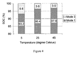
- Figure 4 shows the performance of this temperature compensation algorithm for one particular battery under test.
- a battery charger 1 according to an embodiment of the present invention is shown in Figure 5 .
- the charger comprises an AC/DC converter 2 with secondary side voltage regulation 3 and robust reliable primary side charge current limiting.
- An additional independent over-voltage protection (OVP) 4 protects the charger from over-voltage due to loss of control in the regulation loop. All the necessary timing and program control is done by a microcontroller 5. It commands the voltage control loop 3 and the battery test 6 and generates the interface to the diagnostic unit 7.
- the diagnostic unit provides an indication to the user of the current charge mode of the charger.
- the charger 1 is also connected to a temperature sensor which provides an input of the battery ambient temperature.
- a reliable resistor 8 is used as a power dissipative element.
- a short test load current is regularly drawn (after charging). During the test, the charge current is set to zero. Voltage readings taken during the pulse test are used to generate the signal "Battery OK". In order to neutralize the test load discharge current, the same amount of charge must be given back to the battery. This may be done with a short refresh charge following each test impulse.
- the temperature compensation algorithm of the present invention alters both the charge voltage and the duty cycle of the current pulse simultaneously, in order to compensate for temperature impact.
- the application of temperature compensation to the basic ICC principle provides a number of advantages when compared to the basic ICC principle. Firstly, the potential danger of overcharging at high temperature is alleviated. Furthermore, the danger of undercharging at low temperature is compensated, by charging more energy into the battery in Mode 3. As a result, a more efficient battery charging technology is provided which extends the life of a battery.
Abstract
Description
- The present invention relates to battery charging. In particular, this invention relates to a battery charging system and method suitable for use in standby applications.
- One technique which is commonly used for charging Valve Regulated Lead Acid (VRLA) batteries, which are typically used in standby applications such as emergency systems, is known as float charging. However, it has been found that there are a number of drawbacks associated with float charging. These include the fact that the float charging regime overcharges the battery, and also causes excessive temperatures of the battery cells, which in turn degrades the chemical composition of the electrolyte in the battery, so as to shorten the battery life.
- A more efficient battery charging principle for standby VRLA batteries involves the use of what is known as the Intermittent Charge Control (ICC) principle, as described in reference M Bhatt, W G Hurley, W H Wölfle, "A New Approach to Intermittent Charging of Valve-Regulated Lead-Acid Batteries in Standby Applications", IEEE Transactions on Industrial Electronics, vol. 52, no. 5, pp. 1337-1342, October 2005.
- The ICC principle consists of four distinct operating modes, as shown in
Figure 1 . InMode 1, a battery is charged with a charge current of 0.1Crated A, where Crated is the rated battery capacity in Ah. The purpose ofMode 1 is to charge the battery to a high state of charge (SOC) of over 85%. When the battery voltage triggers the upper threshold voltage (Vut ), the operating mode changes fromMode 1 toMode 2. InMode 2, the battery is kept at open circuit to reduce the battery internal resistances built up inMode 1, and provide more voltage head room forMode 3. When the battery voltage drops below a lower threshold voltage (Vlt ), the operating mode changes fromMode 2 toMode 3. InMode 3, the battery is charged with pulsed-currents with a peak current value of 0.05Crated A, a period of 30 seconds and a current duty cycle (D) of 33.3%. - The purpose of
Mode 3 is to charge the battery to full SOC. When the battery voltage reaches the upper threshold voltage again, the operating mode proceeds toMode 4. InMode 4, the battery is fully charged and it is kept at open circuit. The battery voltage drops due to self-discharging inMode 4. When the battery voltage drops below a restart charge voltage threshold (Vr ), which indicates an SOC of 97%, the charging cycle is restarted starting withMode 1. - The advantage of the ICC principle is that this charging regime prevents the battery from overcharging, while at the same time keeping the battery at high SOC to prevent sulfation.
- However, it has been found that the reaction rate in the electrolyte doubles for every 10°C increase in temperature. This in turn causes corrosion at the positive grid, and increases water loss and generates extra heat, which could lead to thermal runaway.
- Temperature compensation schemes exist for the float battery charging method. This involves the adjustment of the float voltage to prevent thermal runaway when the temperature is high, and prevent cell self-discharge when the temperature is low. The temperature compensated battery charger adjusts the float charging voltage based on the sensed ambient temperature or battery temperature. When the temperature increases, the charging voltage is accordingly decreased.
- However, no temperature compensation technique is currently provided under the ICC principle. It is therefore an object of the present invention to provide a temperature compensation for pulsed battery-charging schemes, such as those using the ICC principle, in order to improve the battery lifetime.
- According to a first aspect of the present invention, there is provided a method for compensating for temperature effects in a pulsed battery-charging scheme with an average charging current less than the root-mean-square (rms) current, characterised by varying the ratio of the average charging current to rms current as a function of the battery ambient temperature. The method may comprise the steps of: when the battery ambient temperature is less than or equal to a threshold temperature, increasing the ratio of the average charging current to rms current as the battery ambient temperature increases; and when the battery ambient temperature is higher than the threshold temperature, maintaining the ratio of the average charging current to rms current at a constant level. The threshold temperature may be equal to or approximately equal to the rated temperature of a battery to be charged.
- Preferably, varying the ratio of average charging current to rms current comprises varying the duty cycle of the pulsed current. In one embodiment, the battery has a rated duty cycle DRated, and a rated temperature TRated, and the method further comprises maintaining the duty cycle at the rated value when the battery ambient temperature is higher than TRated.
- The method may further comprise varying an upper threshold charging voltage as a function of the battery ambient temperature. The method may comprise the steps of: when the battery ambient temperature exceeds a threshold temperature, decreasing the upper threshold charging voltage as the battery ambient temperature increases; and when the battery ambient temperature is less than or equal to the threshold temperature, maintaining the upper threshold charging voltage at a constant level. Where the battery has a rated upper threshold charging voltage Vut Rted, and a rated temperature TRated, the method may comprise maintaining the upper threshold charging voltage at the rated value when the battery ambient temperature is less than or equal to TRated.
- In one embodiment of the invention, the battery has a rated temperature, TRated, and a rated upper threshold charging voltage, Vut rated, and when the battery ambient temperature is higher than TRated, an upper threshold charging voltage is decreased, the ratio of average charging current to rms current is kept constant, and when the battery ambient temperature is less than or equal to TRated, the ratio of average charging current to rms current is decreased while the upper threshold charging voltage is maintained at the rated value.
- In one embodiment, a pulsed battery-charging scheme may comprise charging a battery with a constant current until a certain voltage level is reached. After a relaxation period, the battery is charged for a short period of time with pulse currents and is then kept in an open circuit (or quasi open circuit) condition. When the voltage drops below a defined value, the pulse current charge starts again.
- An advantage of this arrangement is that the battery is prevented from overcharging when the temperature is higher than the rated temperature and, because the ratio of average current to rms current is kept constant (e.g. at the rated value), charging time is reduced and the battery is protected from thermal runaway. When the temperature is low, the charging voltage increases for a given charging current. This low temperature effect is compensated by decreasing the ratio of average current to rms current to counteract the extra voltage rise. Thus, the potential danger of overcharging at high temperature is alleviated and the danger of undercharging at low temperature is compensated by charging more energy into the battery.
- The method is particularly applicable to a pulsed battery-charging scheme that uses the intermittent charge control (ICC) principle. In this embodiment, the method comprises the steps of:
- (a) charging the battery with a constant charge current until the battery voltage reaches a upper threshold charging voltage;
- (b) placing the battery in low current charge, open circuit or quasi open circuit mode until the battery voltage self-discharges to a value below a lower threshold charging voltage;
- (c) charging the battery with a pulsed charging current until the battery voltage reaches the upper threshold charging voltage;
- (d) when the battery voltage reaches the upper threshold charging voltage, placing the battery in open circuit or quasi open circuit mode;
- (e) repeating steps (a) to (d) when the battery voltage drops below a restart charge voltage threshold;
- According to a second aspect of the present invention, there is provided a battery charger system capable of performing the method of the present invention.
-
-
Figure 1 is a graph of the operating modes of the ICC principle; -
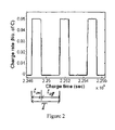
Figure 2 is a graph of a typical current pulse used to charge a battery under the ICC principle; -
Figure 3 is a temperature compensation algorithm for use with ICC principle; and -
Figure 4 shows the performance of the ICC principle when used in conjunction with temperature compensation; and -
Figure 5 is a block diagram of a battery charger according to an embodiment of the present invention. - The method of the present invention will be described with reference to a pulsed battery-charging scheme using the ICC principle. A temperature compensation algorithm for a VRLA battery when being charged using the ICC principle, as a function of temperature, should meet two requirements. Firstly, the battery should maintain high SOC in
Mode 4. Secondly, the rates of water decomposition and grid corrosion should be minimized, so as to prolong the battery service life. - It has been found that when charging a battery using the ICC principle, high battery ambient temperature lowers the charging voltage for a given charge current. Conversely, when the battery ambient temperature is low, the charging voltage increases for a given charge current. The invention uses a temperature compensation algorithm which takes account of the relationship between temperature and the charging voltage, by changing the Vut, the upper threshold voltage, and D, the duty cycle of the periodic current pulse which is used to charge the batteries, i.e. the ratio of when the current pulse is on, ton to the period of the pulse, T, as can be seen from
Figure 2 :
where
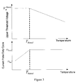
- The algorithm decreases Vut when the temperature is higher than TRated, to prevent the battery from overcharging, while keeping D at the rated value, in order to shorten the charging time and protect the battery from thermal runaway.
- Conversely, when the temperature is lower than TRated, the algorithm decreases D , to alleviate the extra voltage rise, while Vut is kept at the rated value, to avoid charging the battery at a higher voltage. However, D is bounded by D min, which is determined by the minimum average charging current in
Mode 3. - The temperature compensation algorithm which implements these features is therefore a hybrid temperature algorithm, and is expressed in equations (1) and (2) below


where T is the battery ambient temperature in degree Celsius, TRated is the rated temperature of the battery, DRated is the rated duty cycle, D(T) is the duty cycle at temperature T, Dmin is the minimum current duty cycle,
- The change of Vut and D at different temperatures when the algorithm is implemented is illustrated in
Figure 3 . -
Figure 4 shows the performance of this temperature compensation algorithm for one particular battery under test. In this example, the battery under test is a Genesis 12V, 16Ah VRLA battery, G12V16EP, with the charger settings being DRated = 33 %, TRated = 25 °C, D min = 16.7 %, Ncell = 6 , Vtcpc = 0.004 V and
- A
battery charger 1 according to an embodiment of the present invention is shown inFigure 5 . The charger comprises an AC/DC converter 2 with secondaryside voltage regulation 3 and robust reliable primary side charge current limiting. An additional independent over-voltage protection (OVP) 4 protects the charger from over-voltage due to loss of control in the regulation loop. All the necessary timing and program control is done by amicrocontroller 5. It commands thevoltage control loop 3 and thebattery test 6 and generates the interface to thediagnostic unit 7. The diagnostic unit provides an indication to the user of the current charge mode of the charger. Thecharger 1 is also connected to a temperature sensor which provides an input of the battery ambient temperature. - For loading the battery during pulse test (Mode 5), a
reliable resistor 8 is used as a power dissipative element. In order to test the battery, a short test load current is regularly drawn (after charging). During the test, the charge current is set to zero. Voltage readings taken during the pulse test are used to generate the signal "Battery OK". In order to neutralize the test load discharge current, the same amount of charge must be given back to the battery. This may be done with a short refresh charge following each test impulse. - It will therefore be appreciated that while the basic ICC principle adopts constant current to charge a battery until it reaches a certain voltage level, and then it continues the charging by the use of current pulses, the temperature compensation algorithm of the present invention alters both the charge voltage and the duty cycle of the current pulse simultaneously, in order to compensate for temperature impact.
- The application of temperature compensation to the basic ICC principle provides a number of advantages when compared to the basic ICC principle. Firstly, the potential danger of overcharging at high temperature is alleviated. Furthermore, the danger of undercharging at low temperature is compensated, by charging more energy into the battery in
Mode 3. As a result, a more efficient battery charging technology is provided which extends the life of a battery. - The words "comprises/comprising" and the words "having/including" when used herein with reference to the present invention are used to specify the presence of stated features, integers, steps or components but does not preclude the presence or addition of one or more other features, integers, steps, components or groups thereof.
- It is appreciated that certain features of the invention, which are, for clarity, described in the context of separate embodiments, may also be provided in combination in a single embodiment. Conversely, various features of the invention which are, for brevity, described in the context of a single embodiment, may also be provided separately or in any suitable sub-combination.
Claims (13)
- A method for compensating for temperature effects in a pulsed battery-charging scheme with an average charging current less than the root-mean-square (rms) current,
characterised by:varying the ratio of the average charging current to rms current as a function of the battery ambient temperature. - A method as claimed in claim 1, comprising:when the battery ambient temperature is less than or equal to a threshold temperature, increasing the ratio of the average charging current to rms current as the battery ambient temperature increases; andwhen the battery ambient temperature is higher than the threshold temperature, maintaining the ratio of the average charging current to rms current at a constant level.
- A method as claimed in claim 1 or claim 2, wherein varying the ratio of average charging current to rms current comprises varying the duty cycle of the pulsed current.
- A method as claimed in claim 3, wherein the battery-charging scheme is for charging a battery having a rated duty cycle DRated, and a rated temperature TRated, and further characterised by:maintaining the duty cycle at the rated value when the battery ambient temperature is higher than TRated.
- A method as claimed in any preceding claim, further characterised by:varying an upper threshold charging voltage as a function of the battery ambient temperature.
- A method as claimed in claim 5, comprising:when the battery ambient temperature exceeds a threshold temperature, decreasing the upper threshold charging voltage as the battery ambient temperature increases; andwhen the battery ambient temperature is less than or equal to the threshold temperature, maintaining the upper threshold charging voltage at a constant level.
- A method as claimed in claim 5 or claim 6, wherein the battery-charging scheme is for charging a battery having a rated upper threshold charging voltage Vut Rated, and a rated temperature TRated, and further characterised by:maintaining the upper threshold charging voltage at the rated value when the battery ambient temperature is less than or equal to TRated.
- A method as claimed in any preceding claim, wherein the battery-charging scheme is for charging a battery having a rated temperature, TRated, and a rated upper threshold charging voltage, Vut rated, further characterised by:when the battery ambient temperature is higher than TRated, decreasing an upper threshold charging voltage while maintaining the ratio of average charging current to rms current constant; andwhen the battery ambient temperature is less than or equal to TRated, decreasing the ratio of average charging current to rms current while maintaining the upper threshold charging voltage at the rated value.
- A method as claimed in any preceding claim, wherein the pulsed battery-charging scheme uses the intermittent charge control (ICC) principle, and wherein the method comprises the steps of:(a) charging the battery with a constant charge current until the battery voltage reaches a upper threshold charging voltage;(b) placing the battery in low current charge, open circuit or quasi open circuit mode until the battery voltage self-discharges to a value below a lower threshold charging voltage;(c) charging the battery with a pulsed charging current until the battery voltage reaches the upper threshold charging voltage;(d) when the battery voltage reaches the upper threshold charging voltage, placing the battery in open circuit or quasi open circuit mode;(e) repeating steps (a) to (d) when the battery voltage drops below a restart charge voltage threshold;wherein the upper threshold charging voltage and the ratio of average charging current to rms current are temperature-dependent.
- A battery charger using a pulsed battery-charging scheme with an average charging current less than the root-mean-square (rms) current, characterised in that it comprises:means for varying the ratio of the average charging current to rms current as a function of the battery ambient temperature.
- A battery charger as claimed in claim 10, characterised in that it further comprises:means for varying an upper threshold charging voltage as a function of the battery ambient temperature.
- A battery charger as claimed in claim 10 or claim 11, for charging a battery having a rated temperature, TRated, and a rated upper threshold charging voltage, Vut rated, further characterised in that it comprises:means for decreasing an upper threshold charging voltage while maintaining the ratio of average charging current to rms current constant when the battery ambient temperature is higher than TRated; andmeans for decreasing the ratio of average charging current to rms current while maintaining the upper threshold charging voltage at the rated value, when the battery ambient temperature is less than or equal to TRated.
- A battery charger substantially as hereinbefore described with reference to and/or as illustrated in Figure 5 of the accompanying drawings.
Priority Applications (4)
| Application Number | Priority Date | Filing Date | Title |
|---|---|---|---|
| EP07121927A EP2065997B1 (en) | 2007-11-29 | 2007-11-29 | Battery charger and method |
| ES07121927T ES2367589T3 (en) | 2007-11-29 | 2007-11-29 | BATTERY CHARGER AND PROCEDURE. |
| AT07121927T ATE516620T1 (en) | 2007-11-29 | 2007-11-29 | BATTERY CHARGER AND METHOD THEREOF |
| US12/277,095 US8569999B2 (en) | 2007-11-29 | 2008-11-24 | Battery charger and method |
Applications Claiming Priority (1)
| Application Number | Priority Date | Filing Date | Title |
|---|---|---|---|
| EP07121927A EP2065997B1 (en) | 2007-11-29 | 2007-11-29 | Battery charger and method |
Publications (2)
| Publication Number | Publication Date |
|---|---|
| EP2065997A1 true EP2065997A1 (en) | 2009-06-03 |
| EP2065997B1 EP2065997B1 (en) | 2011-07-13 |
Family
ID=39332043
Family Applications (1)
| Application Number | Title | Priority Date | Filing Date |
|---|---|---|---|
| EP07121927A Not-in-force EP2065997B1 (en) | 2007-11-29 | 2007-11-29 | Battery charger and method |
Country Status (4)
| Country | Link |
|---|---|
| US (1) | US8569999B2 (en) |
| EP (1) | EP2065997B1 (en) |
| AT (1) | ATE516620T1 (en) |
| ES (1) | ES2367589T3 (en) |
Cited By (1)
| Publication number | Priority date | Publication date | Assignee | Title |
|---|---|---|---|---|
| US20210396595A1 (en) * | 2018-02-07 | 2021-12-23 | Renault S.A.S. | Method and device for detecting when a predefined temperature threshold is exceeded |
Families Citing this family (14)
| Publication number | Priority date | Publication date | Assignee | Title |
|---|---|---|---|---|
| KR101500439B1 (en) * | 2009-06-04 | 2015-03-10 | 삼성전자 주식회사 | Computer system and control method thereof |
| US8198860B2 (en) * | 2010-02-05 | 2012-06-12 | Daca Electronics Company Limited | Charger with analyzer arrangement |
| US8624559B2 (en) * | 2010-10-14 | 2014-01-07 | GM Global Technology Operations LLC | Excessive current detection controls method |
| IN2015DN01550A (en) * | 2012-09-03 | 2015-07-03 | Robert Bosch Sea Pte Ltd | |
| US20140285135A1 (en) * | 2013-03-22 | 2014-09-25 | Ec Power, Llc | Systems for heating a battery and processes thereof |
| JP5982317B2 (en) * | 2013-03-29 | 2016-08-31 | Kyb株式会社 | Charge control device and hybrid construction machine |
| US10481210B2 (en) * | 2014-07-14 | 2019-11-19 | Ford Global Technologies, Llc | Methods to determine battery cell voltage relaxation time based on cell usage history and temperature |
| DE102014221482A1 (en) * | 2014-10-22 | 2016-04-28 | Ford Global Technologies, Llc | Method for controlling a voltage source for charging a battery of a motor vehicle |
| US10232732B2 (en) * | 2015-01-27 | 2019-03-19 | Ford Global Technologies, Llc | System and method for battery control using RMS current |
| JP6647963B2 (en) * | 2016-05-18 | 2020-02-14 | 日立建機株式会社 | Construction machinery |
| DE102016212554A1 (en) * | 2016-07-11 | 2018-01-11 | Robert Bosch Gmbh | A method of adjusting the voltage provided by a high performance electrochemical store and a system for operating a load |
| US11355793B2 (en) * | 2017-04-27 | 2022-06-07 | Panasonic Intellectual Property Management Co., Ltd. | Power supplying device, power storage system, and charging method |
| CN107394294B (en) * | 2017-07-20 | 2018-09-04 | 浙江谷神能源科技股份有限公司 | For the systems of lithium ion battery charge and discharge, control device and associated method |
| CN111293739B (en) * | 2018-12-10 | 2022-05-17 | 华为技术有限公司 | Charging method and device |
Citations (5)
| Publication number | Priority date | Publication date | Assignee | Title |
|---|---|---|---|---|
| US4065712A (en) * | 1970-10-29 | 1977-12-27 | Societe Des Accumulateurs Fixes Et De Traction | Rapid charging system and method for sealed storage cells |
| WO1993015543A1 (en) * | 1992-01-22 | 1993-08-05 | Electronic Power Technology, Inc. | Method and apparatus for charging, thawing, and formatting a battery |
| US5422560A (en) * | 1991-09-30 | 1995-06-06 | Telcom Semiconductor, Inc. | Battery charger with battery detection circuit |
| US20020036482A1 (en) * | 2000-08-09 | 2002-03-28 | Toshiyuki Nakatsuji | Charging method of rechargeable battery |
| US20050068005A1 (en) * | 2003-09-26 | 2005-03-31 | Takahiro Yamashita | Battery charging apparatus for charging a plurality of batterles |
Family Cites Families (7)
| Publication number | Priority date | Publication date | Assignee | Title |
|---|---|---|---|---|
| US4862013A (en) * | 1987-12-02 | 1989-08-29 | Zenith Electronics Corporation | Constant current source and battery charger |
| KR950703809A (en) * | 1993-07-14 | 1995-09-20 | 에프. 제이. 스미트 | Circuit arrangement for charging rechargeable batteries |
| FR2753580B1 (en) * | 1996-09-16 | 1998-12-04 | Valeo Equip Electr Moteur | ALTERNATOR VOLTAGE REGULATION SYSTEM |
| US5917305A (en) * | 1997-12-11 | 1999-06-29 | Compaq Computer Corporation | Battery control architecture with standardized language |
| US6624618B2 (en) * | 2001-01-25 | 2003-09-23 | Ford Global Technologies, Llc | System and method for vehicle voltage regulation |
| US7501794B2 (en) * | 2004-12-17 | 2009-03-10 | Sigmatel, Inc. | System, method and semiconductor device for charging a secondary battery |
| JP2006288150A (en) * | 2005-04-04 | 2006-10-19 | Hitachi Koki Co Ltd | Charging device for lithium battery |
-
2007
- 2007-11-29 EP EP07121927A patent/EP2065997B1/en not_active Not-in-force
- 2007-11-29 AT AT07121927T patent/ATE516620T1/en not_active IP Right Cessation
- 2007-11-29 ES ES07121927T patent/ES2367589T3/en active Active
-
2008
- 2008-11-24 US US12/277,095 patent/US8569999B2/en not_active Expired - Fee Related
Patent Citations (5)
| Publication number | Priority date | Publication date | Assignee | Title |
|---|---|---|---|---|
| US4065712A (en) * | 1970-10-29 | 1977-12-27 | Societe Des Accumulateurs Fixes Et De Traction | Rapid charging system and method for sealed storage cells |
| US5422560A (en) * | 1991-09-30 | 1995-06-06 | Telcom Semiconductor, Inc. | Battery charger with battery detection circuit |
| WO1993015543A1 (en) * | 1992-01-22 | 1993-08-05 | Electronic Power Technology, Inc. | Method and apparatus for charging, thawing, and formatting a battery |
| US20020036482A1 (en) * | 2000-08-09 | 2002-03-28 | Toshiyuki Nakatsuji | Charging method of rechargeable battery |
| US20050068005A1 (en) * | 2003-09-26 | 2005-03-31 | Takahiro Yamashita | Battery charging apparatus for charging a plurality of batterles |
Non-Patent Citations (2)
| Title |
|---|
| BHATT M ET AL: "A New Approach to Intermittent Charging of Valve-Regulated Lead-Acid Batteries in Standby Applications", IEEE TRANSACTIONS ON INDUSTRIAL ELECTRONICS, IEEE SERVICE CENTER, PISCATAWAY, NJ, vol. 52, no. 5, 1 October 2005 (2005-10-01), pages 1337 - 1342, XP011139894, ISSN: 0278-0046 * |
| M BHATT; W G HURLEY; W H WOLFLE: "A New Approach to Intermittent Charging of Valve-Regulated Lead-Acid Batteries in Standby Applications", IEEE TRANSACTIONS ON INDUSTRIAL ELECTRONICS, vol. 52, no. 5, October 2005 (2005-10-01), pages 1337 - 1342 |
Cited By (1)
| Publication number | Priority date | Publication date | Assignee | Title |
|---|---|---|---|---|
| US20210396595A1 (en) * | 2018-02-07 | 2021-12-23 | Renault S.A.S. | Method and device for detecting when a predefined temperature threshold is exceeded |
Also Published As
| Publication number | Publication date |
|---|---|
| US20090140697A1 (en) | 2009-06-04 |
| EP2065997B1 (en) | 2011-07-13 |
| ATE516620T1 (en) | 2011-07-15 |
| US8569999B2 (en) | 2013-10-29 |
| ES2367589T3 (en) | 2011-11-04 |
Similar Documents
| Publication | Publication Date | Title |
|---|---|---|
| EP2065997B1 (en) | Battery charger and method | |
| US8330427B2 (en) | Charge control circuit, and charging device and battery pack incorporated with the same | |
| US8203314B2 (en) | Surface temperature dependent battery cell charging system | |
| US8581554B2 (en) | Battery charging method and apparatus | |
| EP2592714B1 (en) | Apparatus and method for battery equalization | |
| EP2192649B1 (en) | Power storage system | |
| JP5593849B2 (en) | Battery monitoring device | |
| US20130187465A1 (en) | Power management system | |
| US20090261786A1 (en) | Battery charge compensation | |
| JP4248854B2 (en) | Battery management system and battery pack | |
| US10734828B2 (en) | Battery chargers and associated systems and methods | |
| JP2008283853A (en) | Method for charging battery of autonomic system | |
| Wong et al. | Charge regimes for valve-regulated lead-acid batteries: Performance overview inclusive of temperature compensation | |
| US9906052B2 (en) | Power supply device | |
| JP2010160955A (en) | Method of charging battery pack | |
| JP6965770B2 (en) | Lead-acid battery control device, lead-acid battery device, uninterruptible power supply, power supply system, and charge control method | |
| CN110828913B (en) | Battery charging method and charging system thereof | |
| KR20180031206A (en) | Battery management system and method for protecting a battery from over-discharge | |
| KR20150050215A (en) | Apparatus and method for managing battery pack | |
| JP2004200129A (en) | Device and method for controlling discharge of lead storage battery | |
| JP5878058B2 (en) | Distributed power storage system | |
| CN109344357B (en) | Mixed main power supply capacity calculation method of electric ship | |
| WO2022168677A1 (en) | Control method for zinc battery and power supply system | |
| Wong et al. | Temperature compensation algorithm for interrupted charge control regime for a VRLA battery in standby applications | |
| Yunana et al. | Development of a Fast Charging System Utilizing Charge Profile and Cell Balance Control Technology for Large Capacity Lithium-ion Batteries |
Legal Events
| Date | Code | Title | Description |
|---|---|---|---|
| PUAI | Public reference made under article 153(3) epc to a published international application that has entered the european phase |
Free format text: ORIGINAL CODE: 0009012 |
|
| AK | Designated contracting states |
Kind code of ref document: A1 Designated state(s): AT BE BG CH CY CZ DE DK EE ES FI FR GB GR HU IE IS IT LI LT LU LV MC MT NL PL PT RO SE SI SK TR |
|
| AX | Request for extension of the european patent |
Extension state: AL BA HR MK RS |
|
| 17P | Request for examination filed |
Effective date: 20091117 |
|
| AKX | Designation fees paid |
Designated state(s): AT BE BG CH CY CZ DE DK EE ES FI FR GB GR HU IE IS IT LI LT LU LV MC MT NL PL PT RO SE SI SK TR |
|
| GRAP | Despatch of communication of intention to grant a patent |
Free format text: ORIGINAL CODE: EPIDOSNIGR1 |
|
| GRAS | Grant fee paid |
Free format text: ORIGINAL CODE: EPIDOSNIGR3 |
|
| GRAA | (expected) grant |
Free format text: ORIGINAL CODE: 0009210 |
|
| AK | Designated contracting states |
Kind code of ref document: B1 Designated state(s): AT BE BG CH CY CZ DE DK EE ES FI FR GB GR HU IE IS IT LI LT LU LV MC MT NL PL PT RO SE SI SK TR |
|
| REG | Reference to a national code |
Ref country code: GB Ref legal event code: FG4D |
|
| REG | Reference to a national code |
Ref country code: CH Ref legal event code: EP |
|
| REG | Reference to a national code |
Ref country code: IE Ref legal event code: FG4D |
|
| REG | Reference to a national code |
Ref country code: DE Ref legal event code: R096 Ref document number: 602007015744 Country of ref document: DE Effective date: 20110901 |
|
| REG | Reference to a national code |
Ref country code: NL Ref legal event code: T3 |
|
| REG | Reference to a national code |
Ref country code: ES Ref legal event code: FG2A Ref document number: 2367589 Country of ref document: ES Kind code of ref document: T3 Effective date: 20111104 |
|
| REG | Reference to a national code |
Ref country code: AT Ref legal event code: MK05 Ref document number: 516620 Country of ref document: AT Kind code of ref document: T Effective date: 20110713 |
|
| PG25 | Lapsed in a contracting state [announced via postgrant information from national office to epo] |
Ref country code: LT Free format text: LAPSE BECAUSE OF FAILURE TO SUBMIT A TRANSLATION OF THE DESCRIPTION OR TO PAY THE FEE WITHIN THE PRESCRIBED TIME-LIMIT Effective date: 20110713 Ref country code: IS Free format text: LAPSE BECAUSE OF FAILURE TO SUBMIT A TRANSLATION OF THE DESCRIPTION OR TO PAY THE FEE WITHIN THE PRESCRIBED TIME-LIMIT Effective date: 20111113 Ref country code: PT Free format text: LAPSE BECAUSE OF FAILURE TO SUBMIT A TRANSLATION OF THE DESCRIPTION OR TO PAY THE FEE WITHIN THE PRESCRIBED TIME-LIMIT Effective date: 20111114 Ref country code: SE Free format text: LAPSE BECAUSE OF FAILURE TO SUBMIT A TRANSLATION OF THE DESCRIPTION OR TO PAY THE FEE WITHIN THE PRESCRIBED TIME-LIMIT Effective date: 20110713 Ref country code: BE Free format text: LAPSE BECAUSE OF FAILURE TO SUBMIT A TRANSLATION OF THE DESCRIPTION OR TO PAY THE FEE WITHIN THE PRESCRIBED TIME-LIMIT Effective date: 20110713 Ref country code: FI Free format text: LAPSE BECAUSE OF FAILURE TO SUBMIT A TRANSLATION OF THE DESCRIPTION OR TO PAY THE FEE WITHIN THE PRESCRIBED TIME-LIMIT Effective date: 20110713 |
|
| PG25 | Lapsed in a contracting state [announced via postgrant information from national office to epo] |
Ref country code: CY Free format text: LAPSE BECAUSE OF FAILURE TO SUBMIT A TRANSLATION OF THE DESCRIPTION OR TO PAY THE FEE WITHIN THE PRESCRIBED TIME-LIMIT Effective date: 20110713 Ref country code: PL Free format text: LAPSE BECAUSE OF FAILURE TO SUBMIT A TRANSLATION OF THE DESCRIPTION OR TO PAY THE FEE WITHIN THE PRESCRIBED TIME-LIMIT Effective date: 20110713 Ref country code: AT Free format text: LAPSE BECAUSE OF FAILURE TO SUBMIT A TRANSLATION OF THE DESCRIPTION OR TO PAY THE FEE WITHIN THE PRESCRIBED TIME-LIMIT Effective date: 20110713 Ref country code: GR Free format text: LAPSE BECAUSE OF FAILURE TO SUBMIT A TRANSLATION OF THE DESCRIPTION OR TO PAY THE FEE WITHIN THE PRESCRIBED TIME-LIMIT Effective date: 20111014 Ref country code: SI Free format text: LAPSE BECAUSE OF FAILURE TO SUBMIT A TRANSLATION OF THE DESCRIPTION OR TO PAY THE FEE WITHIN THE PRESCRIBED TIME-LIMIT Effective date: 20110713 Ref country code: LV Free format text: LAPSE BECAUSE OF FAILURE TO SUBMIT A TRANSLATION OF THE DESCRIPTION OR TO PAY THE FEE WITHIN THE PRESCRIBED TIME-LIMIT Effective date: 20110713 |
|
| PG25 | Lapsed in a contracting state [announced via postgrant information from national office to epo] |
Ref country code: CZ Free format text: LAPSE BECAUSE OF FAILURE TO SUBMIT A TRANSLATION OF THE DESCRIPTION OR TO PAY THE FEE WITHIN THE PRESCRIBED TIME-LIMIT Effective date: 20110713 Ref country code: SK Free format text: LAPSE BECAUSE OF FAILURE TO SUBMIT A TRANSLATION OF THE DESCRIPTION OR TO PAY THE FEE WITHIN THE PRESCRIBED TIME-LIMIT Effective date: 20110713 |
|
| PLBE | No opposition filed within time limit |
Free format text: ORIGINAL CODE: 0009261 |
|
| STAA | Information on the status of an ep patent application or granted ep patent |
Free format text: STATUS: NO OPPOSITION FILED WITHIN TIME LIMIT |
|
| PG25 | Lapsed in a contracting state [announced via postgrant information from national office to epo] |
Ref country code: IT Free format text: LAPSE BECAUSE OF FAILURE TO SUBMIT A TRANSLATION OF THE DESCRIPTION OR TO PAY THE FEE WITHIN THE PRESCRIBED TIME-LIMIT Effective date: 20110713 Ref country code: EE Free format text: LAPSE BECAUSE OF FAILURE TO SUBMIT A TRANSLATION OF THE DESCRIPTION OR TO PAY THE FEE WITHIN THE PRESCRIBED TIME-LIMIT Effective date: 20110713 Ref country code: RO Free format text: LAPSE BECAUSE OF FAILURE TO SUBMIT A TRANSLATION OF THE DESCRIPTION OR TO PAY THE FEE WITHIN THE PRESCRIBED TIME-LIMIT Effective date: 20110713 |
|
| 26N | No opposition filed |
Effective date: 20120416 |
|
| PG25 | Lapsed in a contracting state [announced via postgrant information from national office to epo] |
Ref country code: MC Free format text: LAPSE BECAUSE OF NON-PAYMENT OF DUE FEES Effective date: 20111130 Ref country code: DK Free format text: LAPSE BECAUSE OF FAILURE TO SUBMIT A TRANSLATION OF THE DESCRIPTION OR TO PAY THE FEE WITHIN THE PRESCRIBED TIME-LIMIT Effective date: 20110713 |
|
| REG | Reference to a national code |
Ref country code: CH Ref legal event code: PL |
|
| GBPC | Gb: european patent ceased through non-payment of renewal fee |
Effective date: 20111129 |
|
| PG25 | Lapsed in a contracting state [announced via postgrant information from national office to epo] |
Ref country code: LI Free format text: LAPSE BECAUSE OF NON-PAYMENT OF DUE FEES Effective date: 20111130 Ref country code: CH Free format text: LAPSE BECAUSE OF NON-PAYMENT OF DUE FEES Effective date: 20111130 |
|
| REG | Reference to a national code |
Ref country code: DE Ref legal event code: R097 Ref document number: 602007015744 Country of ref document: DE Effective date: 20120416 |
|
| REG | Reference to a national code |
Ref country code: FR Ref legal event code: ST Effective date: 20120731 |
|
| PG25 | Lapsed in a contracting state [announced via postgrant information from national office to epo] |
Ref country code: GB Free format text: LAPSE BECAUSE OF NON-PAYMENT OF DUE FEES Effective date: 20111129 |
|
| PG25 | Lapsed in a contracting state [announced via postgrant information from national office to epo] |
Ref country code: FR Free format text: LAPSE BECAUSE OF NON-PAYMENT OF DUE FEES Effective date: 20111130 |
|
| PGFP | Annual fee paid to national office [announced via postgrant information from national office to epo] |
Ref country code: DE Payment date: 20121130 Year of fee payment: 6 |
|
| PG25 | Lapsed in a contracting state [announced via postgrant information from national office to epo] |
Ref country code: MT Free format text: LAPSE BECAUSE OF FAILURE TO SUBMIT A TRANSLATION OF THE DESCRIPTION OR TO PAY THE FEE WITHIN THE PRESCRIBED TIME-LIMIT Effective date: 20110713 |
|
| PGFP | Annual fee paid to national office [announced via postgrant information from national office to epo] |
Ref country code: ES Payment date: 20121207 Year of fee payment: 6 |
|
| PGFP | Annual fee paid to national office [announced via postgrant information from national office to epo] |
Ref country code: NL Payment date: 20121130 Year of fee payment: 6 |
|
| PG25 | Lapsed in a contracting state [announced via postgrant information from national office to epo] |
Ref country code: LU Free format text: LAPSE BECAUSE OF NON-PAYMENT OF DUE FEES Effective date: 20111129 |
|
| PG25 | Lapsed in a contracting state [announced via postgrant information from national office to epo] |
Ref country code: BG Free format text: LAPSE BECAUSE OF FAILURE TO SUBMIT A TRANSLATION OF THE DESCRIPTION OR TO PAY THE FEE WITHIN THE PRESCRIBED TIME-LIMIT Effective date: 20111013 |
|
| PG25 | Lapsed in a contracting state [announced via postgrant information from national office to epo] |
Ref country code: TR Free format text: LAPSE BECAUSE OF FAILURE TO SUBMIT A TRANSLATION OF THE DESCRIPTION OR TO PAY THE FEE WITHIN THE PRESCRIBED TIME-LIMIT Effective date: 20110713 |
|
| PG25 | Lapsed in a contracting state [announced via postgrant information from national office to epo] |
Ref country code: HU Free format text: LAPSE BECAUSE OF FAILURE TO SUBMIT A TRANSLATION OF THE DESCRIPTION OR TO PAY THE FEE WITHIN THE PRESCRIBED TIME-LIMIT Effective date: 20110713 |
|
| REG | Reference to a national code |
Ref country code: NL Ref legal event code: V1 Effective date: 20140601 |
|
| REG | Reference to a national code |
Ref country code: DE Ref legal event code: R119 Ref document number: 602007015744 Country of ref document: DE Effective date: 20140603 |
|
| PG25 | Lapsed in a contracting state [announced via postgrant information from national office to epo] |
Ref country code: DE Free format text: LAPSE BECAUSE OF NON-PAYMENT OF DUE FEES Effective date: 20140603 Ref country code: NL Free format text: LAPSE BECAUSE OF NON-PAYMENT OF DUE FEES Effective date: 20140601 |
|
| REG | Reference to a national code |
Ref country code: ES Ref legal event code: FD2A Effective date: 20150703 |
|
| PG25 | Lapsed in a contracting state [announced via postgrant information from national office to epo] |
Ref country code: ES Free format text: LAPSE BECAUSE OF NON-PAYMENT OF DUE FEES Effective date: 20131130 |
|
| PGFP | Annual fee paid to national office [announced via postgrant information from national office to epo] |
Ref country code: IE Payment date: 20151202 Year of fee payment: 9 |
|
| REG | Reference to a national code |
Ref country code: IE Ref legal event code: MM4A |
|
| PG25 | Lapsed in a contracting state [announced via postgrant information from national office to epo] |
Ref country code: IE Free format text: LAPSE BECAUSE OF NON-PAYMENT OF DUE FEES Effective date: 20161129 |