EP1614976A1 - Drying device and method of operation therefor - Google Patents
Drying device and method of operation therefor Download PDFInfo
- Publication number
- EP1614976A1 EP1614976A1 EP04724747A EP04724747A EP1614976A1 EP 1614976 A1 EP1614976 A1 EP 1614976A1 EP 04724747 A EP04724747 A EP 04724747A EP 04724747 A EP04724747 A EP 04724747A EP 1614976 A1 EP1614976 A1 EP 1614976A1
- Authority
- EP
- European Patent Office
- Prior art keywords
- compressor
- temperature
- evaporator
- radiator
- throttle
- Prior art date
- Legal status (The legal status is an assumption and is not a legal conclusion. Google has not performed a legal analysis and makes no representation as to the accuracy of the status listed.)
- Withdrawn
Links
Images


Classifications
-
- F—MECHANICAL ENGINEERING; LIGHTING; HEATING; WEAPONS; BLASTING
- F24—HEATING; RANGES; VENTILATING
- F24F—AIR-CONDITIONING; AIR-HUMIDIFICATION; VENTILATION; USE OF AIR CURRENTS FOR SCREENING
- F24F3/00—Air-conditioning systems in which conditioned primary air is supplied from one or more central stations to distributing units in the rooms or spaces where it may receive secondary treatment; Apparatus specially designed for such systems
- F24F3/12—Air-conditioning systems in which conditioned primary air is supplied from one or more central stations to distributing units in the rooms or spaces where it may receive secondary treatment; Apparatus specially designed for such systems characterised by the treatment of the air otherwise than by heating and cooling
- F24F3/14—Air-conditioning systems in which conditioned primary air is supplied from one or more central stations to distributing units in the rooms or spaces where it may receive secondary treatment; Apparatus specially designed for such systems characterised by the treatment of the air otherwise than by heating and cooling by humidification; by dehumidification
- F24F3/153—Air-conditioning systems in which conditioned primary air is supplied from one or more central stations to distributing units in the rooms or spaces where it may receive secondary treatment; Apparatus specially designed for such systems characterised by the treatment of the air otherwise than by heating and cooling by humidification; by dehumidification with subsequent heating, i.e. with the air, given the required humidity in the central station, passing a heating element to achieve the required temperature
-
- D—TEXTILES; PAPER
- D06—TREATMENT OF TEXTILES OR THE LIKE; LAUNDERING; FLEXIBLE MATERIALS NOT OTHERWISE PROVIDED FOR
- D06F—LAUNDERING, DRYING, IRONING, PRESSING OR FOLDING TEXTILE ARTICLES
- D06F58/00—Domestic laundry dryers
- D06F58/32—Control of operations performed in domestic laundry dryers
- D06F58/34—Control of operations performed in domestic laundry dryers characterised by the purpose or target of the control
- D06F58/50—Responding to irregular working conditions, e.g. malfunctioning of blowers
-
- F—MECHANICAL ENGINEERING; LIGHTING; HEATING; WEAPONS; BLASTING
- F26—DRYING
- F26B—DRYING SOLID MATERIALS OR OBJECTS BY REMOVING LIQUID THEREFROM
- F26B21/00—Arrangements or duct systems, e.g. in combination with pallet boxes, for supplying and controlling air or gases for drying solid materials or objects
- F26B21/06—Controlling, e.g. regulating, parameters of gas supply
- F26B21/08—Humidity
- F26B21/086—Humidity by condensing the moisture in the drying medium, which may be recycled, e.g. using a heat pump cycle
-
- D—TEXTILES; PAPER
- D06—TREATMENT OF TEXTILES OR THE LIKE; LAUNDERING; FLEXIBLE MATERIALS NOT OTHERWISE PROVIDED FOR
- D06F—LAUNDERING, DRYING, IRONING, PRESSING OR FOLDING TEXTILE ARTICLES
- D06F2103/00—Parameters monitored or detected for the control of domestic laundry washing machines, washer-dryers or laundry dryers
- D06F2103/28—Air properties
- D06F2103/32—Temperature
-
- D—TEXTILES; PAPER
- D06—TREATMENT OF TEXTILES OR THE LIKE; LAUNDERING; FLEXIBLE MATERIALS NOT OTHERWISE PROVIDED FOR
- D06F—LAUNDERING, DRYING, IRONING, PRESSING OR FOLDING TEXTILE ARTICLES
- D06F2103/00—Parameters monitored or detected for the control of domestic laundry washing machines, washer-dryers or laundry dryers
- D06F2103/28—Air properties
- D06F2103/34—Humidity
-
- D—TEXTILES; PAPER
- D06—TREATMENT OF TEXTILES OR THE LIKE; LAUNDERING; FLEXIBLE MATERIALS NOT OTHERWISE PROVIDED FOR
- D06F—LAUNDERING, DRYING, IRONING, PRESSING OR FOLDING TEXTILE ARTICLES
- D06F2103/00—Parameters monitored or detected for the control of domestic laundry washing machines, washer-dryers or laundry dryers
- D06F2103/28—Air properties
- D06F2103/36—Flow or velocity
-
- D—TEXTILES; PAPER
- D06—TREATMENT OF TEXTILES OR THE LIKE; LAUNDERING; FLEXIBLE MATERIALS NOT OTHERWISE PROVIDED FOR
- D06F—LAUNDERING, DRYING, IRONING, PRESSING OR FOLDING TEXTILE ARTICLES
- D06F2103/00—Parameters monitored or detected for the control of domestic laundry washing machines, washer-dryers or laundry dryers
- D06F2103/50—Parameters monitored or detected for the control of domestic laundry washing machines, washer-dryers or laundry dryers related to heat pumps, e.g. pressure or flow rate
-
- D—TEXTILES; PAPER
- D06—TREATMENT OF TEXTILES OR THE LIKE; LAUNDERING; FLEXIBLE MATERIALS NOT OTHERWISE PROVIDED FOR
- D06F—LAUNDERING, DRYING, IRONING, PRESSING OR FOLDING TEXTILE ARTICLES
- D06F2105/00—Systems or parameters controlled or affected by the control systems of washing machines, washer-dryers or laundry dryers
- D06F2105/16—Air properties
- D06F2105/24—Flow or velocity
-
- D—TEXTILES; PAPER
- D06—TREATMENT OF TEXTILES OR THE LIKE; LAUNDERING; FLEXIBLE MATERIALS NOT OTHERWISE PROVIDED FOR
- D06F—LAUNDERING, DRYING, IRONING, PRESSING OR FOLDING TEXTILE ARTICLES
- D06F2105/00—Systems or parameters controlled or affected by the control systems of washing machines, washer-dryers or laundry dryers
- D06F2105/26—Heat pumps
-
- D—TEXTILES; PAPER
- D06—TREATMENT OF TEXTILES OR THE LIKE; LAUNDERING; FLEXIBLE MATERIALS NOT OTHERWISE PROVIDED FOR
- D06F—LAUNDERING, DRYING, IRONING, PRESSING OR FOLDING TEXTILE ARTICLES
- D06F58/00—Domestic laundry dryers
- D06F58/20—General details of domestic laundry dryers
- D06F58/206—Heat pump arrangements
-
- D—TEXTILES; PAPER
- D06—TREATMENT OF TEXTILES OR THE LIKE; LAUNDERING; FLEXIBLE MATERIALS NOT OTHERWISE PROVIDED FOR
- D06F—LAUNDERING, DRYING, IRONING, PRESSING OR FOLDING TEXTILE ARTICLES
- D06F58/00—Domestic laundry dryers
- D06F58/32—Control of operations performed in domestic laundry dryers
- D06F58/34—Control of operations performed in domestic laundry dryers characterised by the purpose or target of the control
- D06F58/46—Control of the operating time
-
- D—TEXTILES; PAPER
- D06—TREATMENT OF TEXTILES OR THE LIKE; LAUNDERING; FLEXIBLE MATERIALS NOT OTHERWISE PROVIDED FOR
- D06F—LAUNDERING, DRYING, IRONING, PRESSING OR FOLDING TEXTILE ARTICLES
- D06F58/00—Domestic laundry dryers
- D06F58/32—Control of operations performed in domestic laundry dryers
- D06F58/34—Control of operations performed in domestic laundry dryers characterised by the purpose or target of the control
- D06F58/48—Control of the energy consumption
-
- F—MECHANICAL ENGINEERING; LIGHTING; HEATING; WEAPONS; BLASTING
- F25—REFRIGERATION OR COOLING; COMBINED HEATING AND REFRIGERATION SYSTEMS; HEAT PUMP SYSTEMS; MANUFACTURE OR STORAGE OF ICE; LIQUEFACTION SOLIDIFICATION OF GASES
- F25B—REFRIGERATION MACHINES, PLANTS OR SYSTEMS; COMBINED HEATING AND REFRIGERATION SYSTEMS; HEAT PUMP SYSTEMS
- F25B2309/00—Gas cycle refrigeration machines
- F25B2309/06—Compression machines, plants or systems characterised by the refrigerant being carbon dioxide
- F25B2309/061—Compression machines, plants or systems characterised by the refrigerant being carbon dioxide with cycle highest pressure above the supercritical pressure
-
- F—MECHANICAL ENGINEERING; LIGHTING; HEATING; WEAPONS; BLASTING
- F25—REFRIGERATION OR COOLING; COMBINED HEATING AND REFRIGERATION SYSTEMS; HEAT PUMP SYSTEMS; MANUFACTURE OR STORAGE OF ICE; LIQUEFACTION SOLIDIFICATION OF GASES
- F25B—REFRIGERATION MACHINES, PLANTS OR SYSTEMS; COMBINED HEATING AND REFRIGERATION SYSTEMS; HEAT PUMP SYSTEMS
- F25B9/00—Compression machines, plants or systems, in which the refrigerant is air or other gas of low boiling point
- F25B9/002—Compression machines, plants or systems, in which the refrigerant is air or other gas of low boiling point characterised by the refrigerant
- F25B9/008—Compression machines, plants or systems, in which the refrigerant is air or other gas of low boiling point characterised by the refrigerant the refrigerant being carbon dioxide
-
- Y—GENERAL TAGGING OF NEW TECHNOLOGICAL DEVELOPMENTS; GENERAL TAGGING OF CROSS-SECTIONAL TECHNOLOGIES SPANNING OVER SEVERAL SECTIONS OF THE IPC; TECHNICAL SUBJECTS COVERED BY FORMER USPC CROSS-REFERENCE ART COLLECTIONS [XRACs] AND DIGESTS
- Y02—TECHNOLOGIES OR APPLICATIONS FOR MITIGATION OR ADAPTATION AGAINST CLIMATE CHANGE
- Y02B—CLIMATE CHANGE MITIGATION TECHNOLOGIES RELATED TO BUILDINGS, e.g. HOUSING, HOUSE APPLIANCES OR RELATED END-USER APPLICATIONS
- Y02B40/00—Technologies aiming at improving the efficiency of home appliances, e.g. induction cooking or efficient technologies for refrigerators, freezers or dish washers
Definitions
- the present invention relates to a drying apparatus having a heat pump apparatus in which a refrigerant circulates through a compressor, a radiator, a throttle apparatus and an evaporator in this order, wherein air heated by the radiator is introduced into a dry chamber, the air coming out from the dry chamber is cooled by a cooling apparatus, and the air cooled by the cooling apparatus is dehumidified by the evaporator, and the air dehumidified by the evaporator is again heated by the radiator.
- the invention also relates to an operating method of the drying apparatus.
- An electric clothing dryer used in ordinary households uses an electric heater as a heat source which is necessary for drying. Due to the current carrying capacity of a domestic convenience receptacle, its amount of heat is limited, and this causes a bottleneck in reduction of time required for drying clothing. Further, heat used for drying clothing is not reused and is only discharged out, and this is waste of energy.
- a clothing dryer in which a heat pump apparatus is used as a heat source for drying clothing, a portion of drying air is discharged out from a body of the apparatus, thereby reducing the required electricity and achieving high dehumidification efficiency (e.g. , see Japanese Patent Application Laid-open No.H7-178289 (pages 4 to 5, Fig. 1)).
- Fig. 1 shows a conventional clothing drying apparatus described in patent document 1.
- a rotation drum 22 is a dry chamber which is rotatably provided in a body 21 of the drying apparatus and which dries clothing 39 in the dry chamber.
- a rotation drum 22 is driven by a motor 27 through a drum belt 35.
- a blower 23 sends drying air from the rotation drum 22 toward a circulation duct 26 through a filter 24 and a rotation drum-side air intake 25.
- the blower 23 is driven by the motor 27 through a fan belt 28.
- An evaporator 29 is disposed in the circulation duct 26.
- the evaporator 29 evaporates a refrigerant, thereby cooling and dehumidifying the drying air.
- a condenser 30 condenses a refrigerant, thereby heating the drying air flowing in the circulation duct 26.
- the heated drying air is introduced into the circulation duct 26 and is again returned to the dry chamber.
- the compressor 31 generates a pressure difference in a refrigerant.
- a throttle apparatus 32 comprising a capillary tube and the like maintains the pressure difference of the refrigerant.
- the evaporator 29, the condenser 30, the compressor 31 and the throttle apparatus 32 are connected to one another through pipes 33 to constitute a heat pump apparatus.
- a drying apparatus comprises a heat pump apparatus in which a refrigerant circulates through a compressor, a radiator, a throttle apparatus and an evaporator in this order, in which air heated by the radiator is introduced into a dry chamber, the air coming out from the dry chamber is cooled by a cooling apparatus, the air cooled by the cooling apparatus is dehumidified by the evaporator, and the air dehumidified by the evaporator is again heated by the radiator.
- the drying apparatus further comprises compressor input detecting means for detecting input of the compressor, and cooling quantity control means for controlling a cooling quantity of the cooling apparatus using a value detected by the compressor input detecting means.
- drying air can be cooled in accordance with the input of the compressor, an amount of heat corresponding to the compressor input can be discharged outside, and the pressure in the refrigeration cycle can be maintained at predetermined pressure.
- the apparatus further comprises outlet air temperature detecting means for detecting outlet air temperature of the radiator, and refrigeration cycle control means for controlling compressing performance of the compressor using a value detected by the outlet air temperature detecting means.
- the compressor is controlled in accordance with the outlet air temperature of the radiator.
- the increase in radiator outlet temperature i.e., the rising speed of the dry air temperature is quickened immediately after the operation is started for example, and if the refrigerant temperature in the evaporator is lowered, the amount of moisture to be dehumidified can be increased, and the drying time can be shortened.
- the refrigeration cycle control means controls throttle degree of the throttle apparatus using a value detected by the outlet air temperature detecting means.
- the compression ratio of the refrigeration cycle is reduced.
- the input into the compressor can be reduced and energy can be saved.
- the drying apparatus further comprises discharge pressure detecting means for detecting discharge pressure of the compressor, and refrigeration cycle control means for controlling compressing performance of the compressor using a value detected by the discharge pressure detecting means.
- the discharged refrigerant pressure in the compressor is detected and the compressor is controlled.
- the discharge pressure can be adjusted swiftly, the reliability of the compressor and the drying apparatus can reliably be ensured, and the drying air temperature especially immediately after the drying operation is started can swiftly be increased.
- the refrigeration cycle control means controls the throttle degree of the throttle apparatus using a value detected by the discharge pressure detecting means.
- the discharge pressure can further swiftly be adjusted by controlling the throttle apparatus.
- the discharge pressure can be adjusted swiftly, the reliability of the compressor and the drying apparatus can reliably be ensured, and the drying air temperature especially immediately after the drying operation is started can swiftly be increased.
- the drying apparatus further comprises evaporator temperature detecting means for detecting refrigerant temperature of the evaporator, inlet air temperature detecting means for detecting inlet air temperature of the evaporator, inlet air humidity detecting means for detecting inlet air humidity of the evaporator, and refrigeration cycle control means for controlling compressing performance of the compressor based on dew point temperature determined by a value detected by the inlet air temperature detecting means and a value detected by the inlet air humidity detecting means .
- the refrigerant temperature , the inlet air temperature and the inlet air humidity of the evaporator are detected, and the compressor is controlled.
- the dehumidification in the evaporator can reliably be carried out, and frost can be prevented from being formed and thus, the drying operation can be carried out within shorter time, and the drying apparatus can reliably be operated efficiently.
- the refrigeration cycle control means controls the throttle degree of the throttle apparatus based on dew point temperature determined by a value detected by the inlet air temperature detecting means and a value detected by the inlet air humidity detecting means.
- the refrigerant temperature , the inlet air temperature and the inlet air humidity of the evaporator are detected, and the throttle apparatus is controlled.
- the dehumidification in the evaporator can reliably be carried out, and frost can be prevented from being formed and thus , the drying operation can be carried out within shorter time, and the drying apparatus can reliably be operated efficiently.
- An eight aspect of the present invention provides operating method of a drying apparatus comprising a heat pump apparatus in which a refrigerant circulates through a compressor, a radiator, a throttle apparatus and an evaporator in this order, in which air heated by the radiator is introduced into a dry chamber, the air coming out from the dry chamber is cooled by a cooling apparatus, the air cooled by the cooling apparatus is dehumidified by the evaporator, and the air dehumidified by the evaporator is again heated by the radiator, wherein if input of the compressor is increased, cooling quantity of the cooling apparatus is allowed to be increased, and if the input of the compressor is reduced, the cooling quantity of the cooling apparatus is allowed to be reduced.
- drying air can be cooled in accordance with the input of the compressor, an amount of heat corresponding to the compressor input can be discharged outside, and the pressure in the refrigeration cycle can be maintained at predetermined pressure.
- a ninth aspect of the invention provides an operating method of a drying apparatus comprising a heat pump apparatus in which a refrigerant circulates through a compressor, a radiator, a throttle apparatus and an evaporator in this order, in which air heated by the radiator is introduced into a dry chamber, the air coming out from the dry chamber is cooled by a cooling apparatus, the air cooled by the cooling apparatus is dehumidified by the evaporator, and the air dehumidified by the evaporator is again heated by the radiator, wherein if outlet air temperature of the radiator exceeds predetermined temperature, compressing performance of the compressor is allowed to be reduced, and if the outlet air temperature of the radiator becomes equal to or smaller than the predetermined temperature, the compressing performance of the compressor is allowed to be increased.
- the compressor is controlled in accordance with the outlet air temperature of the radiator.
- the increase in radiator outlet temperature i.e., the rising speed of the dry air temperature is quickened immediately after the operation is started for example, and if the refrigerant temperature in the evaporator is lowered, the amount of moisture to be dehumidified can be increased, and the drying time can be shortened.
- the throttle apparatus is controlled in accordance with the outlet air temperature of the radiator.
- the increase in radiator outlet temperature i.e. , the rising speed of the dry air temperature is quickened immediately after the operation is started for example, and if the refrigerant temperature in the evaporator is lowered, the amount of moisture to be dehumidified can be increased, and the drying time can be shortened.
- the outlet air temperature is increased, the compression ratio of the refrigeration cycle is reduced.
- the input into the compressor can be reduced and energy can be saved.
- An eleventh aspect of the invention provides an operating method of a drying apparatus comprising: a heat pump apparatus in which a refrigerant circulates through a compressor, a radiator, a throttle apparatus and an evaporator in this order; evaporator temperature detecting means for detecting refrigerant temperature of the evaporator; inlet air temperature detecting means for detecting inlet air temperature of the evaporator; and inlet air humidity detecting means for detecting inlet air humidity of the evaporator; in which air heated by the radiator is introduced into a dry chamber, the air coming out from the dry chamber is cooled by a cooling apparatus, the air cooled by the cooling apparatus is dehumidified by the evaporator, and the air dehumidified by the evaporator is again heated by the radiator, wherein dew point temperature is calculated using a value detected by the inlet air temperature detecting means and a value detected by the inlet air humidity detecting means, the calculated dew point temperature and refrigerant temperature detected by the evaporator temperature
- the refrigerant temperature, the inlet air temperature and the inlet air humidity of the evaporator are detected, and the compressor is controlled.
- the dehumidification in the evaporator can reliably be carried out, and frost can be prevented from being formed and thus, the drying operation can be carried out within shorter time, and the drying apparatus can reliably be operated efficiently.
- the throttle degree of the throttle apparatus is allowed to be reduced, and if the detected refrigerant temperature is lower than a predetermined temperature, the throttle degree of the throttle apparatus is allowed to be increased.
- the refrigerant temperature, the inlet air temperature and the inlet air humidity of the evaporator are detected, and the throttle apparatus is controlled.
- the dehumidification in the evaporator can reliably be carried out, and frost can be prevented from being formed and thus, the drying operation can be carried out within shorter time, and the drying apparatus can reliably be operated efficiently.
- the discharge pressure can be adjusted swiftly, the reliability of the compressor and the drying apparatus can reliably be ensured, and the drying air temperature especially immediately after the drying operation is started can swiftly be increased.
- the throttle degree of the throttle apparatus is allowed to be increased.
- the discharge pressure can be adjusted swiftly, the reliability of the compressor and the drying apparatus can reliably be ensured, and the drying air temperature especially immediately after the drying operation is started can swiftly be increased.
- carbon dioxide is used as the refrigerant, and the drying apparatus is operated in a state in which high pressure side pressure exceeds critical pressure.
- the inlet side temperature of the refrigerant in the radiator is the same, higher outlet air temperature can be obtained as compared with flon refrigerant, and the drying time can be shortened.
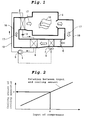
- Fig. 1 is a block diagram of a drying apparatus of a first embodiment of the present invention.
- the drying apparatus of this embodiment uses a refrigerant of flon, carbon dioxide or the like as working fluid, and has a heat pump apparatus.
- a compressor 1 a radiator 2 , a throttle apparatus 3 and an evaporator 4 are connected to one another through pipes 19.
- the drying apparatus includes a dry chamber 5 which dries a subject to be dried 10 such as clothing by drying air 17 heated by the radiator 2, a blower 6 for sending the drying air 17, and a cooling apparatus 7 for cooling the drying air 17 .
- the drying air 17 circulates through the radiator 2, the dry chamber 5 , the cooling apparatus 7 and the evaporator 4 via a duct 16.
- the drying apparatus includes compressor input detecting means 8 for detecting input of the compressor 1, and cooling quantity control means 9 for controlling the cooling quantity of the cooling apparatus 7 based on the detected input of the compressor.
- a subject to be dried 10 is put into the dry chamber 5. If the blower 6 is rotated, a flow of the drying air 17 is generated.
- the drying air 17 is heated by the radiator 2 and enters the dry chamber 5, and absorbs moisture from the subject to be dried 10 in the dry chamber 5 and thus, the drying air 17 becomes humid and then, the drying air 17 is sent to the cooling apparatus 7 by the blower 6 and is cooled, and sent to the evaporator 4.
- the drying air sent to the evaporator 4 is dehumidified and sent to the radiator 2, and is again heated by the radiator 2 and sent to the dry chamber 5. Through this drying cycle, the subject to be dried 10 is dried.
- an amount of heat radiated to the drying air 17 by the radiator 2 becomes greater than an amount of heat absorbed from the drying air 17 in the evaporator 4 by an amount of heat corresponding to the input of the compressor 1. Therefore, if the circulation of the drying air is continued, the amount of heat of the entire drying air is increased, the amount of heat of the refrigerant in the heat pump apparatus is increased, the pressure of the refrigerant is increased and exceeds the motor torque of the compressor 1 soon. Thus, in order to safely operate the heat pump apparatus, it is necessary to discharge the amount of heat of drying air by the cooling apparatus 7.
- Fig. 2 shows a relation between the input of the compressor 1 and a cooling fan air volume set value (e.g. , voltage of fan) of the cooling apparatus 7 for radiating heat outside. That is, if input X of the compressor 1 is detected by the compressor input detecting means 8, it can be determined that the cooling fan air volume set value for discharging out the amount of heat corresponding to the input is Y. Therefore, if control is exercised such that a cooling quantity set value of the cooling apparatus 7 becomes Y based on the relation shown in Fig. 2, an amount of heat corresponding to the input of the compressor 1 can be discharged out, and the pressure in the refrigeration cycle can be maintained at a predetermined pressure.
- a cooling fan air volume set value e.g. , voltage of fan
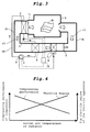
- Fig. 3 is a block diagram showing a drying apparatus of a second embodiment of the invention. Only difference of the structure of the drying apparatus of the second embodiment from those of the first embodiment will be explained. The same can be applied to third and subsequent embodiments also.
- the drying apparatus of the second embodiment includes, in addition to the structure of the first embodiment, outlet air temperature detecting means 11 for detecting the outlet air temperature of the radiator 2, and refrigeration cycle control means 18 for controlling compressing performance of the compressor 1 and the throttle degree of the throttle apparatus 3 based on the outlet air temperature.
- the outlet air temperature detecting means 11 comprises a temperature sensor for example, and detects the temperature of the drying air 17 at the outlet of the radiator 2.
- the refrigeration cycle control means 18 comprises means for adjusting operating frequency of an electric motor which drives the compressor and controlling the compressing performance of the compressor 1, and means for controlling the throttle degree of the throttle apparatus 3 comprising an expansion valve for example.
- the refrigeration cycle control means 18 of the second embodiment may control the cooling quantity control means 9 including refrigeration cycle control means 18 of later-described third to fifth embodiments.
- Fig. 4 shows relations between the outlet air temperature of the radiator 2 and the throttle degree of the throttle apparatus 3 and between the outlet air temperature of the radiator 2 and the compressing performance (e.g., operating frequency) of the compressor 1
- Fig. 5 is a Mollier diagram of a refrigeration cycle for explaining the operation of the drying apparatus of the second embodiment.
- the refrigeration cycle can be shifted to a refrigeration cycle in which a compression ratio is small, safety is high and COP (coefficient of performance) is high, as in a case shown in Fig. 5 in which A cycle is shifted to B cycle.
- the compressor 1 and the throttle apparatus 3 are controlled with variation in outlet air temperature of the radiator 2 in the above explanation, they may be controlled in a stepwise manner, or control may be exercised such that the compressing performance of the compressor 1 is increased and the throttle degree of the throttle apparatus 3 is reduced until the outlet air temperature of the radiator 2 reaches a first predetermined temperature, and the compressing performance of the compressor 1 is reduced and the throttle degree of the throttle apparatus 3 is increased after the outlet air temperature of the radiator 2 exceeds a second predetermined temperature.
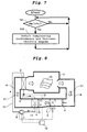
- Fig. 6 is a block diagram showing a drying apparatus of a third embodiment of the invention
- Fig. 7 is a control flowchart of the drying apparatus of the third embodiment.
- the drying apparatus of the third embodiment includes discharge pressure detecting means 12 for detecting discharge pressure of the compressor 1 , and refrigeration cycle control means 18 for controlling the compressing performance of the compressor 1 and the throttle degree of the throttle apparatus 3 based on the detected discharge pressure.
- step 41 the refrigeration cycle control means 18 compares discharge pressure Pm detected by the discharge pressure detecting means 12 and target upper limit set pressure Px (e.g., 12MPa) with each other. If Pm is greater than Px, it is determined that the discharge pressure exceeds a reliability reference value of the compressor, the procedure is proceeded to step 42, where control is exercised such that the compressing performance of the compressor 1 is reduced and the throttle degree of the throttle apparatus 3 is increased. Then, the procedure is returned to step 41. With this, it is possible to swiftly and largely reduce the discharge pressure. If Pm is equal to or smaller than Px, the procedure is returned to step 41.
- Px target upper limit set pressure
- the discharge pressure of the compressor 1 is detected, and the compressing performance of the compressor 1 and the throttle degree of the throttle apparatus 3 are controlled based on the detected discharge pressure.
- the discharge pressure it becomes possible to directly control the discharge pressure itself , and the discharge pressure can swiftly be adjusted.
- the drying apparatuses of the third and second embodiments are combined, the dry air temperature immediately after the operation is started can swiftly be increased, the discharge pressure can swiftly and reliably be returned to the original pressure, and the drying apparatus can safely be operated.
- Fig. 8 is a block diagram showing a drying apparatus of a fourth embodiment of the invention
- Fig. 9 is a control flowchart of the drying apparatus of the fourth embodiment.
- the drying apparatus of the fourth embodiment includes evaporator temperature detecting means 13 for detecting the refrigerant temperature of the evaporator 4, inlet air temperature detecting means 14 for detecting the inlet air temperature of the evaporator 4, inlet air humidity detecting means 15 for detecting the inlet air humidity of the evaporator 4, and refrigeration cycle control means 18 for controlling the compressing performance of the compressor 1 and the throttle degree of the throttle apparatus 3 based on the detected evaporator temperature and the dew point temperature.
- step 51 the refrigeration cycle control means 18 calculates the dew point temperature Tr (e.g. , 2°C) from the temperature detected by the inlet air temperature detecting means 14 and the humidity detected by the inlet air humidity detecting means 15. Then, the procedure is proceeded to step 52, where the evaporator temperature Te detected by the evaporator temperature detecting means 13 and the dew point temperature Tr are compared with each other.
- Tr dew point temperature
- the procedure is proceeded to step 54, where control is exercised such that the throttle degree of the throttle apparatus 3 is reduced and the compressing performance of the compressor 1 is increased, and the procedure is returned to step 51.
- control is exercised such that the throttle degree of the throttle apparatus 3 is reduced and the compressing performance of the compressor 1 is increased, and the procedure is returned to step 51.
- Te is smaller than Tr in step 52, the procedure is proceeded to step 53, where the evaporator temperature Te and a frost formation set value (i.e., 0°C) are compared with each other. If Te is equal to or greater than the set value, it is determined that frost is not formed in the evaporator 4, and the procedure is returned to step 51.
- a frost formation set value i.e., 0°C
- Te is smaller than the set value in step 53, it is determined that there is a possibility that frost is formed in the evaporator 4, and the procedure is proceeded to step 55. Then, control is exercised such that the throttle degree of the throttle apparatus 3 is increased and the compressing performance of the compressor 1 is reduced, and the procedure is returned to step 51. With this determination and control operation, since the refrigerant temperature in the evaporator 4 is reduced and frost is prevented from being formed, it is possible to prevent the heat transfer coefficient in the evaporator 4 from being reduced and to prevent ventilation resistance from being increased.
- the evaporator temperature of the evaporator 4 and the dew point temperature of inlet air of the evaporator 4 are detected, and the throttle degree of the throttle apparatus 3 and/or compressing performance of the compressor 1 is controlled. With this, the evaporator 4 is reliably dehumidified and frost can be prevented from being formed. Thus, it is possible to dry within shorter time, and to provide a drying apparatus having high reliability and efficiency, and to provide an operating method of the drying apparatus.
- a drying apparatus of a fifth embodiment of the invention will be explained with reference to Figs. 10 and 11.
- the heat pump apparatus of any of first to fourth embodiments is used, and carbon dioxide is used as the refrigerant.
- the radiator of the drying apparatus of the fifth embodiment is operated in a state in which its high pressure side pressure exceeds the critical pressure.
- Fig. 10 schematically shows variations of temperatures of refrigerant and air in the radiator of the drying apparatus.
- Fig. 11 schematically shows variation of temperatures of refrigerant and air in the radiator 2 when flon refrigerant is used.
- the refrigerant in the case of flon refrigerant, the refrigerant is brought from a superheat state into a gas-liquid two phase state in the radiator 2, and the state is changed into a supercool state, the refrigerant heat-exchanges with air, and the air side outlet temperature in the radiator 2 rises to C.
- the drying apparatus of the fifth embodiment if carbon dioxide is used in the heat pump apparatus as a refrigerant in which the heat exchange of the radiator 2 can be carried out in the supercritical state, the temperature of the drying air 17 can further be increased. Therefore, it is possible to further shorten the drying time, and to provide a drying apparatus having high drying efficiency.
- drying apparatus for drying clothing is described in the embodiments, the drying apparatus can also be used for drying plateware, garbage and the like.
- the amount of heat to be discharged out can always be adjusted by detecting the input of the compressor and controlling the cooling quantity of the cooling apparatus. Therefore, it is possible to further shorten the drying time and to save energy while carrying out stable refrigeration cycle operation from the beginning of operation.
- the compressing performance of the compressor and the throttle degree of the throttle apparatus are controlled in accordance with the outlet air temperature of the radiator.
- the rising speed of the radiator outlet temperature of the radiator i.e., the drying air temperature
- the compression ratio of the refrigeration cycle is reduced.
- the discharge pressure of the compressor is detected, and the compressing performance of the compressor and the throttle degree of the throttle apparatus are controlled. With this, the discharge pressure can swiftly be controlled. Therefore, it is possible to more reliably secure the reliability of the compressor and the drying apparatus, and the drying air temperature immediately after the drying operation is started can swiftly be increased.
- the refrigerant temperature of the evaporator, as well as the inlet air temperature and the inlet air humidity of the evaporator are detected, and the compressing performance of the compressor and the throttle degree of the throttle apparatus are controlled. With this, the dehumidification in the evaporator can reliably be carried out, and frost can be prevented from being formed and thus, the drying operation can be carried out within shorter time, and the drying apparatus can reliably be operated efficiently.
- the drying air temperature can further be increased.
- the drying time can be shortened, and the drying apparatus can be operated efficiently.
- the drying apparatus can be used not only for drying clothing, but also for drying plateware, garbage and the like.
Abstract
Description
- The present invention relates to a drying apparatus having a heat pump apparatus in which a refrigerant circulates through a compressor, a radiator, a throttle apparatus and an evaporator in this order, wherein air heated by the radiator is introduced into a dry chamber, the air coming out from the dry chamber is cooled by a cooling apparatus, and the air cooled by the cooling apparatus is dehumidified by the evaporator, and the air dehumidified by the evaporator is again heated by the radiator. The invention also relates to an operating method of the drying apparatus.
- An electric clothing dryer used in ordinary households uses an electric heater as a heat source which is necessary for drying. Due to the current carrying capacity of a domestic convenience receptacle, its amount of heat is limited, and this causes a bottleneck in reduction of time required for drying clothing. Further, heat used for drying clothing is not reused and is only discharged out, and this is waste of energy.
- There is proposed a clothing dryer in which a heat pump apparatus is used as a heat source for drying clothing, a portion of drying air is discharged out from a body of the apparatus, thereby reducing the required electricity and achieving high dehumidification efficiency (e.g. , see Japanese Patent Application Laid-open No.H7-178289 (
pages 4 to 5, Fig. 1)). Fig. 1 shows a conventional clothing drying apparatus described inpatent document 1. - In this drying apparatus, a
rotation drum 22 is a dry chamber which is rotatably provided in abody 21 of the drying apparatus and which driesclothing 39 in the dry chamber. Arotation drum 22 is driven by amotor 27 through adrum belt 35. Ablower 23 sends drying air from therotation drum 22 toward acirculation duct 26 through afilter 24 and a rotation drum-side air intake 25. Theblower 23 is driven by themotor 27 through afan belt 28. - An
evaporator 29 is disposed in thecirculation duct 26. Theevaporator 29 evaporates a refrigerant, thereby cooling and dehumidifying the drying air. Acondenser 30 condenses a refrigerant, thereby heating the drying air flowing in thecirculation duct 26. The heated drying air is introduced into thecirculation duct 26 and is again returned to the dry chamber. Thecompressor 31 generates a pressure difference in a refrigerant. Athrottle apparatus 32 comprising a capillary tube and the like maintains the pressure difference of the refrigerant. Theevaporator 29, thecondenser 30, thecompressor 31 and thethrottle apparatus 32 are connected to one another throughpipes 33 to constitute a heat pump apparatus. - However, when the clothing is to be dried using such a drying apparatus, since the temperature of the drying air, a heat exchange loss between the body and outside, a moisture amount included in the clothing to be dried are gradually varied with drying time, it is necessary to always control the optimal amount of heat to be discharged outside. If heat which is greater than the optimal amount of heat to be discharged is discharged outside, the drying time is increased, and the electricity consumption amount is increased.
- If the amount of heat of the drying air is excessively increased, pressure in a refrigeration cycle of the heat pump apparatus adversely rises, and there is a problem that the stable operation can not be carried out in the refrigeration cycle.
- It is an object of the present invention to provide a drying apparatus which can be operated stably in a refrigeration cycle by cooling the drying air to avoid an influence on the refrigeration cycle caused by increase in the amount of heat of the drying air, and to provide an operating method of the drying apparatus.
- It is another object of the invention to provide a drying apparatus capable of shortening the drying time of a subject to be dried, and to provide an operating method of the drying apparatus.
- It is another object of the invention to provide a drying apparatus having high reliability and an operating method of the drying apparatus.
- A drying apparatus according to a first aspect of the present invention comprises a heat pump apparatus in which a refrigerant circulates through a compressor, a radiator, a throttle apparatus and an evaporator in this order, in which air heated by the radiator is introduced into a dry chamber, the air coming out from the dry chamber is cooled by a cooling apparatus, the air cooled by the cooling apparatus is dehumidified by the evaporator, and the air dehumidified by the evaporator is again heated by the radiator. The drying apparatus further comprises compressor input detecting means for detecting input of the compressor, and cooling quantity control means for controlling a cooling quantity of the cooling apparatus using a value detected by the compressor input detecting means.
- According to this aspect, drying air can be cooled in accordance with the input of the compressor, an amount of heat corresponding to the compressor input can be discharged outside, and the pressure in the refrigeration cycle can be maintained at predetermined pressure.
- According to a second aspect of the invention, in the drying apparatus of the first aspect, the apparatus further comprises outlet air temperature detecting means for detecting outlet air temperature of the radiator, and refrigeration cycle control means for controlling compressing performance of the compressor using a value detected by the outlet air temperature detecting means.
- According to this aspect, the compressor is controlled in accordance with the outlet air temperature of the radiator. With this, if the increase in radiator outlet temperature, i.e., the rising speed of the dry air temperature is quickened immediately after the operation is started for example, and if the refrigerant temperature in the evaporator is lowered, the amount of moisture to be dehumidified can be increased, and the drying time can be shortened.
- According to a third aspect of the invention, in the drying apparatus of the second aspect, the refrigeration cycle control means controls throttle degree of the throttle apparatus using a value detected by the outlet air temperature detecting means.
- According to this aspect, as the outlet air temperature is increased for example, the compression ratio of the refrigeration cycle is reduced. Thus, the input into the compressor can be reduced and energy can be saved.
- According to a fourth aspect of the invention, in the drying apparatus of the first aspect, the drying apparatus further comprises discharge pressure detecting means for detecting discharge pressure of the compressor, and refrigeration cycle control means for controlling compressing performance of the compressor using a value detected by the discharge pressure detecting means.
- According to this aspect, the discharged refrigerant pressure in the compressor is detected and the compressor is controlled. With this, the discharge pressure can be adjusted swiftly, the reliability of the compressor and the drying apparatus can reliably be ensured, and the drying air temperature especially immediately after the drying operation is started can swiftly be increased.
- According to a fifth aspect of the invention, in the drying apparatus of the fourth aspect, the refrigeration cycle control means controls the throttle degree of the throttle apparatus using a value detected by the discharge pressure detecting means.
- According to this aspect, the discharge pressure can further swiftly be adjusted by controlling the throttle apparatus. With this, the discharge pressure can be adjusted swiftly, the reliability of the compressor and the drying apparatus can reliably be ensured, and the drying air temperature especially immediately after the drying operation is started can swiftly be increased.
- According to a sixth aspect of the invention, in the drying apparatus of the first aspect, the drying apparatus further comprises evaporator temperature detecting means for detecting refrigerant temperature of the evaporator, inlet air temperature detecting means for detecting inlet air temperature of the evaporator, inlet air humidity detecting means for detecting inlet air humidity of the evaporator, and refrigeration cycle control means for controlling compressing performance of the compressor based on dew point temperature determined by a value detected by the inlet air temperature detecting means and a value detected by the inlet air humidity detecting means .
- According to this aspect, the refrigerant temperature , the inlet air temperature and the inlet air humidity of the evaporator are detected, and the compressor is controlled. With this, the dehumidification in the evaporator can reliably be carried out, and frost can be prevented from being formed and thus, the drying operation can be carried out within shorter time, and the drying apparatus can reliably be operated efficiently.
- According to a seventh aspect of the invention, in the drying apparatus of the sixth aspect, the refrigeration cycle control means controls the throttle degree of the throttle apparatus based on dew point temperature determined by a value detected by the inlet air temperature detecting means and a value detected by the inlet air humidity detecting means.
- According to this aspect, the refrigerant temperature , the inlet air temperature and the inlet air humidity of the evaporator are detected, and the throttle apparatus is controlled. With this, the dehumidification in the evaporator can reliably be carried out, and frost can be prevented from being formed and thus , the drying operation can be carried out within shorter time, and the drying apparatus can reliably be operated efficiently.
- An eight aspect of the present invention provides operating method of a drying apparatus comprising a heat pump apparatus in which a refrigerant circulates through a compressor, a radiator, a throttle apparatus and an evaporator in this order, in which air heated by the radiator is introduced into a dry chamber, the air coming out from the dry chamber is cooled by a cooling apparatus, the air cooled by the cooling apparatus is dehumidified by the evaporator, and the air dehumidified by the evaporator is again heated by the radiator, wherein if input of the compressor is increased, cooling quantity of the cooling apparatus is allowed to be increased, and if the input of the compressor is reduced, the cooling quantity of the cooling apparatus is allowed to be reduced.
- According to this aspect, drying air can be cooled in accordance with the input of the compressor, an amount of heat corresponding to the compressor input can be discharged outside, and the pressure in the refrigeration cycle can be maintained at predetermined pressure.
- A ninth aspect of the invention provides an operating method of a drying apparatus comprising a heat pump apparatus in which a refrigerant circulates through a compressor, a radiator, a throttle apparatus and an evaporator in this order, in which air heated by the radiator is introduced into a dry chamber, the air coming out from the dry chamber is cooled by a cooling apparatus, the air cooled by the cooling apparatus is dehumidified by the evaporator, and the air dehumidified by the evaporator is again heated by the radiator, wherein if outlet air temperature of the radiator exceeds predetermined temperature, compressing performance of the compressor is allowed to be reduced, and if the outlet air temperature of the radiator becomes equal to or smaller than the predetermined temperature, the compressing performance of the compressor is allowed to be increased.
- According to this aspect, the compressor is controlled in accordance with the outlet air temperature of the radiator. With this, if the increase in radiator outlet temperature, i.e., the rising speed of the dry air temperature is quickened immediately after the operation is started for example, and if the refrigerant temperature in the evaporator is lowered, the amount of moisture to be dehumidified can be increased, and the drying time can be shortened.
- According to a tenth aspect of the invention, in the operating method of the drying apparatus of the ninth aspect, if the outlet air temperature of the radiator exceeds the predetermined temperature, throttle degree of the throttle apparatus is allowed to be increased, and if the outlet air temperature of the radiator becomes equal to or smaller than the predetermined temperature, the throttle degree of the throttle apparatus is allowed to be reduced.
- According to this aspect, the throttle apparatus is controlled in accordance with the outlet air temperature of the radiator. With this, if the increase in radiator outlet temperature, i.e. , the rising speed of the dry air temperature is quickened immediately after the operation is started for example, and if the refrigerant temperature in the evaporator is lowered, the amount of moisture to be dehumidified can be increased, and the drying time can be shortened. Further, as the outlet air temperature is increased, the compression ratio of the refrigeration cycle is reduced. Thus, the input into the compressor can be reduced and energy can be saved.
- An eleventh aspect of the invention provides an operating method of a drying apparatus comprising: a heat pump apparatus in which a refrigerant circulates through a compressor, a radiator, a throttle apparatus and an evaporator in this order; evaporator temperature detecting means for detecting refrigerant temperature of the evaporator; inlet air temperature detecting means for detecting inlet air temperature of the evaporator; and inlet air humidity detecting means for detecting inlet air humidity of the evaporator; in which air heated by the radiator is introduced into a dry chamber, the air coming out from the dry chamber is cooled by a cooling apparatus, the air cooled by the cooling apparatus is dehumidified by the evaporator, and the air dehumidified by the evaporator is again heated by the radiator, wherein dew point temperature is calculated using a value detected by the inlet air temperature detecting means and a value detected by the inlet air humidity detecting means, the calculated dew point temperature and refrigerant temperature detected by the evaporator temperature detecting means are compared with each other, and if the detected refrigerant temperature is higher than the dew point temperature, compressing performance of the compressor is allowed to be increased, and if the detected refrigerant temperature is lower than a predetermined temperature, the compressing performance of the compressor is allowed to be reduced.
- According to this aspect, the refrigerant temperature, the inlet air temperature and the inlet air humidity of the evaporator are detected, and the compressor is controlled. With this, the dehumidification in the evaporator can reliably be carried out, and frost can be prevented from being formed and thus, the drying operation can be carried out within shorter time, and the drying apparatus can reliably be operated efficiently.
- According to a twelfth aspect of the invention, in the operating method of the drying apparatus of the eleventh aspect, if the detected refrigerant temperature is higher than the dew point temperature, the throttle degree of the throttle apparatus is allowed to be reduced, and if the detected refrigerant temperature is lower than a predetermined temperature, the throttle degree of the throttle apparatus is allowed to be increased.
- According to this aspect, the refrigerant temperature, the inlet air temperature and the inlet air humidity of the evaporator are detected, and the throttle apparatus is controlled. With this, the dehumidification in the evaporator can reliably be carried out, and frost can be prevented from being formed and thus, the drying operation can be carried out within shorter time, and the drying apparatus can reliably be operated efficiently.
- According to a thirteenth aspect of the invention, in the operating method of the drying apparatus of any one of the eight to twelfth aspects, if discharge pressure of the compressor exceeds predetermined pressure, the compressing performance of the compressor is allowed to be reduced.
- According to this aspect, the discharge pressure can be adjusted swiftly, the reliability of the compressor and the drying apparatus can reliably be ensured, and the drying air temperature especially immediately after the drying operation is started can swiftly be increased.
- According to a fourteenth aspect of the invention, in the operating method of the drying apparatus of the thirteenth aspect, if the discharge pressure of the compressor exceeds a predetermined pressure, the throttle degree of the throttle apparatus is allowed to be increased.
- According to this aspect, the discharge pressure can be adjusted swiftly, the reliability of the compressor and the drying apparatus can reliably be ensured, and the drying air temperature especially immediately after the drying operation is started can swiftly be increased.
- According to a fifteenth aspect of the invention, in the drying apparatus of any one of first to seventh aspects , carbon dioxide is used as the refrigerant, and the drying apparatus is operated in a state in which high pressure side pressure exceeds critical pressure.
- According to this aspect, if the inlet side temperature of the refrigerant in the radiator is the same, higher outlet air temperature can be obtained as compared with flon refrigerant, and the drying time can be shortened.
- According to a sixteenth aspect of the invention, in the operating method of the drying apparatus of any one of the eighth to twelfth aspects, carbon dioxide is used as the refrigerant, and the drying apparatus is operated in a state in which high pressure side pressure exceeds critical pressure.
- According to this aspect, if the inlet side temperature of the refrigerant in the radiator is the same, higher outlet air temperature can be obtained as compared with flon refrigerant, and the drying time can be shortened.
-
- Fig. 1 is a block diagram of a drying apparatus of a first embodiment of the present invention;
- Fig. 2 shows a relation between input of a compressor and a cooling quantity of a cooling apparatus according to the first embodiment;
- Fig. 3 is a block diagram of a drying apparatus of a second embodiment of the invention;
- Fig. 4 shows relations between an outlet air temperature of a radiator and throttle degree of a throttle apparatus and between an outlet air temperature of a radiator and a compressing performance according to the second embodiment;
- Fig. 5 is a Mollier diagram showing a refrigeration cycle of the second embodiment;
- Fig. 6 is a block diagram showing a drying apparatus of a third embodiment of the invention;
- Fig. 7 is a control flowchart of a drying apparatus of a third embodiment;
- Fig. 8 is a block diagram showing a drying apparatus of a fourth embodiment of the invention;
- Fig. 9 is a control flowchart of the drying apparatus of the fourth embodiment;
- Fig. 10 shows temperature variations of air and a refrigerant in a radiator of a drying apparatus of a fifth embodiment according to the invention;
- Fig. 11 shows temperature variation if air and a refrigerant in a radiator of a drying apparatus when a flon refrigerant is used; and
- Fig. 12 is a block diagram of a conventional drying apparatus.
- Embodiments of a drying apparatus of the present invention will be explained below with reference to the drawings.
- Fig. 1 is a block diagram of a drying apparatus of a first embodiment of the present invention. The drying apparatus of this embodiment uses a refrigerant of flon, carbon dioxide or the like as working fluid, and has a heat pump apparatus. In the heat pump apparatus, a
compressor 1, aradiator 2 , athrottle apparatus 3 and anevaporator 4 are connected to one another throughpipes 19. The drying apparatus includes adry chamber 5 which dries a subject to be dried 10 such as clothing by dryingair 17 heated by theradiator 2, ablower 6 for sending the dryingair 17, and acooling apparatus 7 for cooling the dryingair 17 . The dryingair 17 circulates through theradiator 2, thedry chamber 5 , thecooling apparatus 7 and theevaporator 4 via aduct 16. The drying apparatus includes compressorinput detecting means 8 for detecting input of thecompressor 1, and cooling quantity control means 9 for controlling the cooling quantity of thecooling apparatus 7 based on the detected input of the compressor. - The operation of the drying apparatus will be explained below.
- First, a subject to be dried 10 is put into the
dry chamber 5. If theblower 6 is rotated, a flow of the dryingair 17 is generated. The dryingair 17 is heated by theradiator 2 and enters thedry chamber 5, and absorbs moisture from the subject to be dried 10 in thedry chamber 5 and thus, the dryingair 17 becomes humid and then, the dryingair 17 is sent to thecooling apparatus 7 by theblower 6 and is cooled, and sent to theevaporator 4. The drying air sent to theevaporator 4 is dehumidified and sent to theradiator 2, and is again heated by theradiator 2 and sent to thedry chamber 5. Through this drying cycle, the subject to be dried 10 is dried. - Here, in the refrigeration cycle in the heat pump apparatus, an amount of heat radiated to the drying
air 17 by theradiator 2 becomes greater than an amount of heat absorbed from the dryingair 17 in theevaporator 4 by an amount of heat corresponding to the input of thecompressor 1. Therefore, if the circulation of the drying air is continued, the amount of heat of the entire drying air is increased, the amount of heat of the refrigerant in the heat pump apparatus is increased, the pressure of the refrigerant is increased and exceeds the motor torque of thecompressor 1 soon. Thus, in order to safely operate the heat pump apparatus, it is necessary to discharge the amount of heat of drying air by thecooling apparatus 7. - The operation of the cooling quantity control means 9 of the
cooling apparatus 7 will be explained with reference to Fig. 2. - Fig. 2 shows a relation between the input of the
compressor 1 and a cooling fan air volume set value (e.g. , voltage of fan) of thecooling apparatus 7 for radiating heat outside. That is, if input X of thecompressor 1 is detected by the compressorinput detecting means 8, it can be determined that the cooling fan air volume set value for discharging out the amount of heat corresponding to the input is Y. Therefore, if control is exercised such that a cooling quantity set value of thecooling apparatus 7 becomes Y based on the relation shown in Fig. 2, an amount of heat corresponding to the input of thecompressor 1 can be discharged out, and the pressure in the refrigeration cycle can be maintained at a predetermined pressure. - By detecting the input of the
compressor 1 and controlling the cooling quantity of thecooling apparatus 7 in this manner, it is possible to always adjust the amount of heat to be discharged out. Therefore, it is possible to shorten the drying time to save energy while stably carrying out the refrigeration cycle operation from the beginning of the operation. - Fig. 3 is a block diagram showing a drying apparatus of a second embodiment of the invention. Only difference of the structure of the drying apparatus of the second embodiment from those of the first embodiment will be explained. The same can be applied to third and subsequent embodiments also.
- The drying apparatus of the second embodiment includes, in addition to the structure of the first embodiment, outlet air temperature detecting means 11 for detecting the outlet air temperature of the
radiator 2, and refrigeration cycle control means 18 for controlling compressing performance of thecompressor 1 and the throttle degree of thethrottle apparatus 3 based on the outlet air temperature. - The outlet air
temperature detecting means 11 comprises a temperature sensor for example, and detects the temperature of the dryingair 17 at the outlet of theradiator 2. The refrigeration cycle control means 18 comprises means for adjusting operating frequency of an electric motor which drives the compressor and controlling the compressing performance of thecompressor 1, and means for controlling the throttle degree of thethrottle apparatus 3 comprising an expansion valve for example. The refrigeration cycle control means 18 of the second embodiment may control the cooling quantity control means 9 including refrigeration cycle control means 18 of later-described third to fifth embodiments. - The operation of the drying apparatus will be explained.
- Fig. 4 shows relations between the outlet air temperature of the
radiator 2 and the throttle degree of thethrottle apparatus 3 and between the outlet air temperature of theradiator 2 and the compressing performance (e.g., operating frequency) of thecompressor 1, and Fig. 5 is a Mollier diagram of a refrigeration cycle for explaining the operation of the drying apparatus of the second embodiment. - Since the outlet air temperature of the
radiator 2 immediately after the operation of the heat pump apparatus is started is low, control is exercised such that the throttle degree of thethrottle apparatus 3 is reduced, and the operating frequency of thecompressor 1 is increased. With this, the heat exchange amount of theradiator 2 can be increased and thus, the outlet air temperature of theradiator 2 can be increased more rapidly. The refrigerant temperature of theevaporator 4 is reduced by reducing the throttle degree of thethrottle apparatus 3. Therefore, the amount of moisture to be absorbed can be increased and the drying time can be shortened. Control is exercised such that the throttle degree of thethrottle apparatus 3 is increased and the operating frequency of thecompressor 1 is reduced, as predetermined time is elapsed after the start of the operation and as the outlet air temperature of theradiator 2 is increased,. That is, when the outlet temperature of theradiator 2 is high, the throttle degree of thethrottle apparatus 3 is increased such that the heat exchange amount given to theradiator 2 is reduced, and the operating frequency of thecompressor 1 is reduced. With this configuration, the refrigeration cycle can be shifted to a refrigeration cycle in which a compression ratio is small, safety is high and COP (coefficient of performance) is high, as in a case shown in Fig. 5 in which A cycle is shifted to B cycle. - By controlling the throttle degree of the
throttle apparatus 3 and the operating frequency of thecompressor 1 in accordance with the outlet air temperature of theradiator 2 in this manner, the rising speed of the outlet temperature of theradiator 2, i. e. , the dry air temperature, immediately after the start of the operation is increased, and as the outlet air temperature is increased, the compression ratio of the refrigeration cycle is reduced. With this configuration, power required for thecompressor 1 can be reduced, and energy can be saved. - Although the
compressor 1 and thethrottle apparatus 3 are controlled with variation in outlet air temperature of theradiator 2 in the above explanation, they may be controlled in a stepwise manner, or control may be exercised such that the compressing performance of thecompressor 1 is increased and the throttle degree of thethrottle apparatus 3 is reduced until the outlet air temperature of theradiator 2 reaches a first predetermined temperature, and the compressing performance of thecompressor 1 is reduced and the throttle degree of thethrottle apparatus 3 is increased after the outlet air temperature of theradiator 2 exceeds a second predetermined temperature. - Fig. 6 is a block diagram showing a drying apparatus of a third embodiment of the invention, and Fig. 7 is a control flowchart of the drying apparatus of the third embodiment.
- The drying apparatus of the third embodiment includes discharge pressure detecting means 12 for detecting discharge pressure of the
compressor 1 , and refrigeration cycle control means 18 for controlling the compressing performance of thecompressor 1 and the throttle degree of thethrottle apparatus 3 based on the detected discharge pressure. - The operation of the drying apparatus will be explained below.
- As shown in Fig. 7, in step 41, the refrigeration cycle control means 18 compares discharge pressure Pm detected by the discharge
pressure detecting means 12 and target upper limit set pressure Px (e.g., 12MPa) with each other. If Pm is greater than Px, it is determined that the discharge pressure exceeds a reliability reference value of the compressor, the procedure is proceeded to step 42, where control is exercised such that the compressing performance of thecompressor 1 is reduced and the throttle degree of thethrottle apparatus 3 is increased. Then, the procedure is returned to step 41. With this, it is possible to swiftly and largely reduce the discharge pressure. If Pm is equal to or smaller than Px, the procedure is returned to step 41. - In the drying apparatus of the third embodiment, the discharge pressure of the
compressor 1 is detected, and the compressing performance of thecompressor 1 and the throttle degree of thethrottle apparatus 3 are controlled based on the detected discharge pressure. With this, it becomes possible to directly control the discharge pressure itself , and the discharge pressure can swiftly be adjusted. Thus, it is possible to swiftly and reliably solve the problem of the abnormal rise of the discharge pressure, and reliability of the compressor and the drying apparatus can be enhanced. - If the drying apparatuses of the third and second embodiments are combined, the dry air temperature immediately after the operation is started can swiftly be increased, the discharge pressure can swiftly and reliably be returned to the original pressure, and the drying apparatus can safely be operated.
- Fig. 8 is a block diagram showing a drying apparatus of a fourth embodiment of the invention, and Fig. 9 is a control flowchart of the drying apparatus of the fourth embodiment.
- The drying apparatus of the fourth embodiment includes evaporator temperature detecting means 13 for detecting the refrigerant temperature of the
evaporator 4, inlet air temperature detecting means 14 for detecting the inlet air temperature of theevaporator 4, inlet air humidity detecting means 15 for detecting the inlet air humidity of theevaporator 4, and refrigeration cycle control means 18 for controlling the compressing performance of thecompressor 1 and the throttle degree of thethrottle apparatus 3 based on the detected evaporator temperature and the dew point temperature. - The operation of the drying apparatus will be explained.
- As shown in Fig. 9, in step 51, the refrigeration cycle control means 18 calculates the dew point temperature Tr (e.g. , 2°C) from the temperature detected by the inlet air
temperature detecting means 14 and the humidity detected by the inlet airhumidity detecting means 15. Then, the procedure is proceeded to step 52, where the evaporator temperature Te detected by the evaporatortemperature detecting means 13 and the dew point temperature Tr are compared with each other. - If the Te is equal to or greater than Tr, it is determined that the
evaporator 4 can not dehumidify, the procedure is proceeded to step 54, where control is exercised such that the throttle degree of thethrottle apparatus 3 is reduced and the compressing performance of thecompressor 1 is increased, and the procedure is returned to step 51. With this determination and control operation, since the refrigerant temperature at theevaporator 4 is reduced and becomes equal to or smaller than the dew point temperature, the dehumidification in theevaporator 4 can be carried out. - If Te is smaller than Tr in step 52, the procedure is proceeded to step 53, where the evaporator temperature Te and a frost formation set value (i.e., 0°C) are compared with each other. If Te is equal to or greater than the set value, it is determined that frost is not formed in the
evaporator 4, and the procedure is returned to step 51. - If Te is smaller than the set value in step 53, it is determined that there is a possibility that frost is formed in the
evaporator 4, and the procedure is proceeded to step 55. Then, control is exercised such that the throttle degree of thethrottle apparatus 3 is increased and the compressing performance of thecompressor 1 is reduced, and the procedure is returned to step 51. With this determination and control operation, since the refrigerant temperature in theevaporator 4 is reduced and frost is prevented from being formed, it is possible to prevent the heat transfer coefficient in theevaporator 4 from being reduced and to prevent ventilation resistance from being increased. - In the drying apparatus of the fourth embodiment, the evaporator temperature of the
evaporator 4 and the dew point temperature of inlet air of theevaporator 4 are detected, and the throttle degree of thethrottle apparatus 3 and/or compressing performance of thecompressor 1 is controlled. With this, theevaporator 4 is reliably dehumidified and frost can be prevented from being formed. Thus, it is possible to dry within shorter time, and to provide a drying apparatus having high reliability and efficiency, and to provide an operating method of the drying apparatus. - A drying apparatus of a fifth embodiment of the invention will be explained with reference to Figs. 10 and 11. In the fifth embodiment, the heat pump apparatus of any of first to fourth embodiments is used, and carbon dioxide is used as the refrigerant. The radiator of the drying apparatus of the fifth embodiment is operated in a state in which its high pressure side pressure exceeds the critical pressure. Fig. 10 schematically shows variations of temperatures of refrigerant and air in the radiator of the drying apparatus. Fig. 11 schematically shows variation of temperatures of refrigerant and air in the
radiator 2 when flon refrigerant is used. - That is, as shown in Fig. 11, in the case of flon refrigerant, the refrigerant is brought from a superheat state into a gas-liquid two phase state in the
radiator 2, and the state is changed into a supercool state, the refrigerant heat-exchanges with air, and the air side outlet temperature in theradiator 2 rises to C. - On the other hand, as shown in Fig. 10, when carbon dioxide is used as a refrigerant and the apparatus is operated in a state in which the high pressure side pressure exceeds the critical pressure, the heat exchange in the
radiator 2 does not cause the gas-liquid phase change. Therefore, a temperature differencet between the air side outlet temperature and the refrigerant side inlet temperature can be made smaller than a temperature difference T in the case of the flon refrigerant, and the outlet air temperature of the
radiator 2 becomes D. That is, if the refrigerant side inlet temperature To is the same temperature, the outlet air temperature D in the case of carbon dioxide refrigerant can be made higher than the outlet air temperature C in the case of the flon refrigerant. - In the drying apparatus of the fifth embodiment, if carbon dioxide is used in the heat pump apparatus as a refrigerant in which the heat exchange of the
radiator 2 can be carried out in the supercritical state, the temperature of the dryingair 17 can further be increased. Therefore, it is possible to further shorten the drying time, and to provide a drying apparatus having high drying efficiency. - Although the drying apparatus for drying clothing is described in the embodiments, the drying apparatus can also be used for drying plateware, garbage and the like.
- As apparent from the above description, according to the drying apparatus of the present invention, the amount of heat to be discharged out can always be adjusted by detecting the input of the compressor and controlling the cooling quantity of the cooling apparatus. Therefore, it is possible to further shorten the drying time and to save energy while carrying out stable refrigeration cycle operation from the beginning of operation.
- Further, according to the drying apparatus of the invention, the compressing performance of the compressor and the throttle degree of the throttle apparatus are controlled in accordance with the outlet air temperature of the radiator. With this, the rising speed of the radiator outlet temperature of the radiator, i.e., the drying air temperature, immediately after the start of the operation is increased, and as the outlet air temperature is increased, the compression ratio of the refrigeration cycle is reduced. With this configuration, power required for the compressor can be reduced and energy can be saved.
- According to the drying apparatus of the invention, the discharge pressure of the compressor is detected, and the compressing performance of the compressor and the throttle degree of the throttle apparatus are controlled. With this, the discharge pressure can swiftly be controlled. Therefore, it is possible to more reliably secure the reliability of the compressor and the drying apparatus, and the drying air temperature immediately after the drying operation is started can swiftly be increased.
- The refrigerant temperature of the evaporator, as well as the inlet air temperature and the inlet air humidity of the evaporator are detected, and the compressing performance of the compressor and the throttle degree of the throttle apparatus are controlled. With this, the dehumidification in the evaporator can reliably be carried out, and frost can be prevented from being formed and thus, the drying operation can be carried out within shorter time, and the drying apparatus can reliably be operated efficiently.
- In the high side pressure, since the heat pump apparatus is operated under the supercritical pressure, the drying air temperature can further be increased. Thus, the drying time can be shortened, and the drying apparatus can be operated efficiently.
- According to the present invention, as described above, the drying apparatus can be used not only for drying clothing, but also for drying plateware, garbage and the like.
Claims (16)
- A drying apparatus comprising a heat pump apparatus in which a refrigerant circulates through a compressor, a radiator, a throttle apparatus and an evaporator in this order, in which air heated by said radiator is introduced into a dry chamber, the air coming out from said dry chamber is cooled by a cooling apparatus, the air cooled by said cooling apparatus is dehumidified by said evaporator, and the air dehumidified by said evaporator is again heated by said radiator, wherein said drying apparatus further comprises compressor input detecting means for detecting input of said compressor, and cooling quantity control means for controlling a cooling quantity of said cooling apparatus using a value detected by said compressor input detecting means.
- The drying apparatus according to claim 1, further comprising outlet air temperature detecting means for detecting outlet air temperature of said radiator, and refrigeration cycle control means for controlling compressing performance of said compressor using a value detected by said outlet air temperature detecting means.
- The drying apparatus according to claim 2, wherein said refrigeration cycle control means controls throttle degree of said throttle apparatus using a value detected by said outlet air temperature detecting means.
- The drying apparatus according to claim 1, further comprising discharge pressure detecting means for detecting discharge pressure of said compressor, and refrigeration cycle control means for controlling compressing performance of said compressor using a value detected by said discharge pressure detecting means.
- The drying apparatus according to claim 4, wherein said refrigeration cycle control means controls the throttle degree of said throttle apparatus using a value detected by said discharge pressure detecting means.
- The drying apparatus according to claim 1, further comprising evaporator temperature detecting means for detecting refrigerant temperature of said evaporator, inlet air temperature detecting means for detecting inlet air temperature of said evaporator, inlet air humidity detecting means for detecting inlet air humidity of said evaporator, and refrigeration cycle control means for controlling compressing performance of said compressor based on dew point temperature determined by a value detected by said inlet air temperature detecting means and a value detected by said inlet air humidity detecting means.
- The drying apparatus according to claim 6, wherein said refrigeration cycle control means controls the throttle degree of said throttle apparatus based on dew point temperature determined by a value detected by said inlet air temperature detecting means and a value detected by said inlet air humidity detecting means.
- An operating method of a drying apparatus comprising a heat pump apparatus in which a refrigerant circulates through a compressor, a radiator, a throttle apparatus and an evaporator in this order, in which air heated by said radiator is introduced into a dry chamber, the air coming out from said dry chamber is cooled by a cooling apparatus, the air cooled by said cooling apparatus is dehumidified by said evaporator, and the air dehumidified by said evaporator is again heated by said radiator, wherein if input of said compressor is increased, cooling quantity of said cooling apparatus is allowed to be increased, and if the input of said compressor is reduced, the cooling quantity of said cooling apparatus is allowed to be reduced.
- An operating method of a drying apparatus comprising a heat pump apparatus in which a refrigerant circulates through a compressor, a radiator, a throttle apparatus and an evaporator in this order, in which air heated by said radiator is introduced into a dry chamber, the air coming out from said dry chamber is cooled by a cooling apparatus, the air cooled by said cooling apparatus is dehumidified by said evaporator, and the air dehumidified by said evaporator is again heated by said radiator, wherein if outlet air temperature of said radiator exceeds predetermined temperature, compressing performance of said compressor is allowed to be reduced, and if the outlet air temperature of said radiator becomes equal to or smaller than the predetermined temperature, the compressing performance of said compressor is allowed to be increased.
- The operating method of the drying apparatus according to claim 9, wherein if the outlet air temperature of said radiator exceeds the predetermined temperature, throttle degree of said throttle apparatus is allowed to be increased, and if the outlet air temperature of said radiator becomes equal to or smaller than the predetermined temperature, the throttle degree of the throttle apparatus is allowed to be reduced.
- An operating method of a drying apparatus comprising: a heat pump apparatus in which a refrigerant circulates through a compressor, a radiator, a throttle apparatus and an evaporator in this order; evaporator temperature detecting means for detecting refrigerant temperature of said evaporator; inlet air temperature detecting means for detecting inlet air temperature of said evaporator; and inlet air humidity detecting means for detecting inlet air humidity of said evaporator; in which air heated by said radiator is introduced into a dry chamber, the air coming out from said dry chamber is cooled by a cooling apparatus, the air cooled by said cooling apparatus is dehumidified by said evaporator, and the air dehumidified by said evaporator is again heated by said radiator, wherein dew point temperature is calculated using a value detected by said inlet air temperature detecting means and a value detected by said inlet air humidity detecting means, the calculated dew point temperature and refrigerant temperature detected by said evaporator temperature detecting means are compared with each other, and if the detected refrigerant temperature is higher than the dew point temperature, compressing performance of said compressor is allowed to be increased, and if the detected refrigerant temperature is lower than a predetermined temperature, the compressing performance of said compressor is allowed to be reduced.
- The operating method of the drying apparatus according to claim 11, wherein if the detected refrigerant temperature is higher than the dew point temperature, the throttle degree of the throttle apparatus is allowed to be reduced, and if the detected refrigerant temperature is lower than a predetermined temperature, the throttle degree of the throttle apparatus is allowed to be increased.
- The operating method of the drying apparatus according to any one of claims 8 to 12, wherein if discharge pressure of said compressor exceeds predetermined pressure, the compressing performance of said compressor is allowed to be reduced.
- The operating method of the drying apparatus according to claim 13, wherein if the discharge pressure of said compressor exceeds a predetermined pressure, the throttle degree of said throttle apparatus is allowed to be increased.
- The drying apparatus according to any one of claims 1 to 7, wherein carbon dioxide is used as the refrigerant, and the drying apparatus is operated in a state in which high pressure side pressure exceeds critical pressure.
- The operating method of the drying apparatus according to any one of claims 8 to 12 , wherein carbon dioxide is used as the refrigerant, and the drying apparatus is operated in a state in which high pressure side pressure exceeds critical pressure.
Applications Claiming Priority (2)
| Application Number | Priority Date | Filing Date | Title |
|---|---|---|---|
| JP2003099240 | 2003-04-02 | ||
| PCT/JP2004/004688 WO2004090431A1 (en) | 2003-04-02 | 2004-03-31 | Drying device and method of operation therefor |
Publications (2)
| Publication Number | Publication Date |
|---|---|
| EP1614976A1 true EP1614976A1 (en) | 2006-01-11 |
| EP1614976A4 EP1614976A4 (en) | 2006-08-02 |
Family
ID=33156691
Family Applications (1)
| Application Number | Title | Priority Date | Filing Date |
|---|---|---|---|
| EP04724747A Withdrawn EP1614976A4 (en) | 2003-04-02 | 2004-03-31 | Drying device and method of operation therefor |
Country Status (4)
| Country | Link |
|---|---|
| US (1) | US7191543B2 (en) |
| EP (1) | EP1614976A4 (en) |
| CN (1) | CN100343593C (en) |
| WO (1) | WO2004090431A1 (en) |
Cited By (8)
| Publication number | Priority date | Publication date | Assignee | Title |
|---|---|---|---|---|
| WO2011046803A3 (en) * | 2009-10-14 | 2011-07-28 | Carrier Corporation | Dehumidification control in refrigerant vapor compression systems |
| BE1019056A3 (en) * | 2009-12-02 | 2012-02-07 | Atlas Copco Airpower Nv | METHOD FOR REFRIGERATING A GAS |
| RU2452804C2 (en) * | 2007-05-30 | 2012-06-10 | Электролюкс Хоум Продактс Корпорейшн Н.В. | Household drying device for clothes |
| RU2467110C2 (en) * | 2007-11-19 | 2012-11-20 | Электролюкс Хоум Продактс Корпорейшн Н.В. | Household dryer for clothes |
| EP2586906A1 (en) * | 2011-10-25 | 2013-05-01 | Electrolux Home Products Corporation N.V. | A laundry dryer with a heat pump system |
| EP2733255A1 (en) * | 2012-11-16 | 2014-05-21 | Electrolux Home Products Corporation N.V. | Method for operating a laundry treatment apparatus and laundry treatment apparatus |
| EP3428335A1 (en) * | 2013-01-25 | 2019-01-16 | LG Electronics Inc. -1- | Garment processing apparatus |
| US20190145043A1 (en) * | 2017-11-16 | 2019-05-16 | Haier Us Appliance Solutions, Inc. | Dryer appliances including an air circulation duct |
Families Citing this family (57)
| Publication number | Priority date | Publication date | Assignee | Title |
|---|---|---|---|---|
| JP2004116899A (en) * | 2002-09-26 | 2004-04-15 | Matsushita Electric Ind Co Ltd | Heat pump type drier |
| KR100556503B1 (en) * | 2002-11-26 | 2006-03-03 | 엘지전자 주식회사 | Control Method of Drying Time for Dryer |
| JP3696224B2 (en) * | 2003-03-19 | 2005-09-14 | 株式会社グリーンセイジュ | Drying system |
| CN100453922C (en) * | 2004-04-09 | 2009-01-21 | 松下电器产业株式会社 | Drying equipment |
| KR20060033065A (en) * | 2004-10-14 | 2006-04-19 | 엘지전자 주식회사 | (a) condensing type dryer and method of controlling the same |
| US20060218812A1 (en) * | 2005-02-01 | 2006-10-05 | Brown Michael E | Apparatus and method for drying clothes |
| ES2279674B1 (en) * | 2005-03-23 | 2008-08-01 | Ibai, S. Coop. | CLOTHING AND DRYING CLOTHING CLOTHING. |
| DE102005057764A1 (en) * | 2005-12-02 | 2007-06-06 | BSH Bosch und Siemens Hausgeräte GmbH | clothes dryer |
| DE102006026251A1 (en) * | 2006-06-06 | 2007-12-13 | BSH Bosch und Siemens Hausgeräte GmbH | Apparatus and method for drying laundry |
| US8500960B2 (en) * | 2007-01-20 | 2013-08-06 | Dais Analytic Corporation | Multi-phase selective mass transfer through a membrane |
| DE112008000374T5 (en) * | 2007-02-08 | 2010-03-11 | Lg Electronics Inc. | Hot air generating device and dryer with this |
| KR100811487B1 (en) * | 2007-02-13 | 2008-03-07 | 엘지전자 주식회사 | Ductless dryer |
| KR101366561B1 (en) * | 2007-03-06 | 2014-02-25 | 삼성전자주식회사 | Washing machine and dry control method thereof |
| DE102007018787A1 (en) * | 2007-04-20 | 2008-10-23 | BSH Bosch und Siemens Hausgeräte GmbH | Method for operating a condensation dryer with a heat pump, and suitable condensation dryer for this purpose |
| US8627581B2 (en) | 2007-08-23 | 2014-01-14 | Michael E. Brown | Heat delivery system for a fabric care appliance |
| DE102007052839A1 (en) * | 2007-11-06 | 2009-05-07 | BSH Bosch und Siemens Hausgeräte GmbH | Dryer with heat pump circuit |
| WO2009074455A1 (en) * | 2007-12-11 | 2009-06-18 | BSH Bosch und Siemens Hausgeräte GmbH | Household appliance comprising a first air conduit and a heat pump |
| DE102007061519A1 (en) * | 2007-12-20 | 2009-06-25 | BSH Bosch und Siemens Hausgeräte GmbH | A laundry drying apparatus having a moisture determining device and methods of operating a clothes drying machine |
| PL2077350T3 (en) * | 2007-12-31 | 2011-12-30 | Electrolux Home Products Corp Nv | Electric household appliance and relative operating method |
| EP2147999A1 (en) * | 2008-07-24 | 2010-01-27 | Electrolux Home Products Corporation N.V. | Home laundry drier |
| JP5253909B2 (en) * | 2008-07-25 | 2013-07-31 | 株式会社東芝 | Washing and drying machine |
| CN101713141B (en) * | 2008-09-30 | 2011-12-07 | 三洋电机株式会社 | Heat pump drying machine |
| JP2010104579A (en) * | 2008-10-30 | 2010-05-13 | Toshiba Corp | Washing machine |
| DE102008055087A1 (en) * | 2008-12-22 | 2010-06-24 | BSH Bosch und Siemens Hausgeräte GmbH | Dryer with heat pump and recirculated air and process for its operation |
| JP2012125352A (en) * | 2010-12-14 | 2012-07-05 | Samsung Electronics Co Ltd | Clothes dryer |
| EP2487290B1 (en) * | 2011-02-10 | 2014-05-07 | Electrolux Home Products Corporation N.V. | Home laundry drier |
| AU2012237106B2 (en) | 2011-03-29 | 2016-01-07 | Lg Electronics Inc. | Controlling method for clothes dryer |
| US9834882B2 (en) | 2011-07-07 | 2017-12-05 | Haier Us Appliance Solutions, Inc. | Device and method for heat pump based clothes dryer |
| DE102011078922A1 (en) * | 2011-07-11 | 2013-01-17 | BSH Bosch und Siemens Hausgeräte GmbH | Exhaust air drying with additional heating and heat exchanger unit |
| EP2573252B1 (en) * | 2011-09-26 | 2014-05-07 | Electrolux Home Products Corporation N.V. | Laundry treatment apparatus with heat pump |
| PL2764152T3 (en) * | 2011-10-04 | 2016-03-31 | Arcelik As | Heat pump laundry dryer |
| EP2586905B1 (en) * | 2011-10-25 | 2020-07-22 | Electrolux Home Products Corporation N.V. | A laundry dryer with a heat pump system |
| EP2612965B1 (en) * | 2012-01-05 | 2018-04-25 | Electrolux Home Products Corporation N.V. | Appliance and method for drying laundry |
| US9417009B2 (en) * | 2012-03-06 | 2016-08-16 | Lg Electronics Inc. | Controlling method for a washing machine |
| KR101978170B1 (en) * | 2012-10-22 | 2019-05-14 | 엘지전자 주식회사 | Clothes treating apparatus indicating energy efficiency and method for indicating energy efficiency thereof |
| JP6352614B2 (en) * | 2013-10-31 | 2018-07-04 | 東芝ライフスタイル株式会社 | Washing and drying machine |
| CN104631069A (en) * | 2013-11-07 | 2015-05-20 | 杭州三花研究院有限公司 | Clothes dryer and control method thereof |
| KR101613963B1 (en) * | 2014-12-08 | 2016-04-20 | 엘지전자 주식회사 | Clothes treating apparatus with a heat pump system |
| EP3031975B1 (en) * | 2014-12-08 | 2019-08-21 | LG Electronics Inc. | Condensing type clothes dryer having a heat pump cycle and a method for controlling a condensing type clothes dryer having a heat pump cycle |
| KR101632013B1 (en) * | 2014-12-08 | 2016-06-21 | 엘지전자 주식회사 | Condensing type clothes dryer having a heat pump cycle and control method for the same |
| CN104566784B (en) * | 2014-12-11 | 2017-09-26 | 广东美的制冷设备有限公司 | Control method, device and the dehumidifier of dehumidifier |
| CN105841287B (en) * | 2015-01-12 | 2018-07-10 | 广东美的制冷设备有限公司 | The control method of frequency-changeable compressor, device and dehumidifier in dehumidifier |
| CN105839375A (en) * | 2015-01-12 | 2016-08-10 | 青岛海尔洗衣机有限公司 | Clothes dryer control method and clothes dryer |
| CN105986455B (en) * | 2015-02-11 | 2019-11-26 | 青岛海尔洗衣机有限公司 | A kind of frequency conversion heat pump dryer expansion valve control method |
| CN104990227B (en) * | 2015-07-28 | 2017-09-19 | 中国计量学院 | A kind of control method of energy-saving type refrigeration and dehumidification machine |
| US10919249B2 (en) | 2016-02-19 | 2021-02-16 | Albert Mardikian | Apparatus for pressing and dehydrating of waste |
| CN105546937A (en) * | 2016-02-23 | 2016-05-04 | 中山市丰申电器有限公司 | Dehumidifier |
| US20170343232A1 (en) * | 2016-05-27 | 2017-11-30 | Bard Manufacturing Company, Inc. | Proportional dehumidifier control |
| CN106679081B (en) * | 2016-12-14 | 2019-05-31 | 青岛海尔空调器有限总公司 | A kind of air conditioner and its drying control method |
| CN107036194B (en) * | 2017-05-27 | 2023-04-07 | 山东美诺邦马节能科技有限公司 | High-temperature water-cooling double-cold-source dehumidifying fresh air ventilator unit |
| CN107543333B (en) * | 2017-08-14 | 2023-07-25 | 珠海格力电器股份有限公司 | Heat pump drying system and control method thereof |
| KR102408516B1 (en) * | 2017-11-20 | 2022-06-13 | 엘지전자 주식회사 | Control method of the clothes drier |
| KR101943361B1 (en) * | 2018-04-10 | 2019-04-17 | 엘지전자 주식회사 | A controlling method for a washing machine |
| KR101943360B1 (en) * | 2018-04-10 | 2019-04-17 | 엘지전자 주식회사 | A controlling method for a washing machine |
| CN109883158A (en) * | 2019-03-25 | 2019-06-14 | 杨鑫 | A kind of high efficiency convection stoving machine |
| CN110715541A (en) * | 2019-10-14 | 2020-01-21 | 南京航空航天大学 | High-temperature agricultural product drying equipment and method based on supercritical carbon dioxide energy storage |
| CN115562128A (en) * | 2022-11-03 | 2023-01-03 | 格瑞环保科技(深圳)有限公司 | Intelligent control system for multi-effect high-temperature overlapping type drying of garbage |
Citations (6)
| Publication number | Priority date | Publication date | Assignee | Title |
|---|---|---|---|---|
| US4603489A (en) * | 1984-10-05 | 1986-08-05 | Michael Goldberg | Heat pump closed loop drying |
| US4800655A (en) * | 1986-07-07 | 1989-01-31 | Elze Company, Ltd. | Solvent recovery system |
| EP0467188A1 (en) * | 1990-07-19 | 1992-01-22 | Bosch-Siemens HausgerÀ¤te GmbH | Clothes dryer with heat pump |
| DE4216106A1 (en) * | 1992-05-15 | 1993-11-18 | Licentia Gmbh | Revolving clothes dryer for shortened drying time - comprises air circulated by blower and heat exchanger operated only when working is reached, for heater utilisation redn. |
| DE4409607A1 (en) * | 1993-04-21 | 1994-10-27 | Miele & Cie | Condensation-type laundry drier with a heat pump |
| EP1291597A1 (en) * | 2001-09-05 | 2003-03-12 | Esswein S.A. | Process and apparatus for drying by air circulation |
Family Cites Families (8)
| Publication number | Priority date | Publication date | Assignee | Title |
|---|---|---|---|---|
| US3673698A (en) * | 1970-11-25 | 1972-07-04 | Albert S Guerard | Process for freeze drying with carbon dioxide |
| IT1160889B (en) * | 1978-10-26 | 1987-03-11 | Berti Furic | DRYING SYSTEM PARTICULARLY FOR TIMBER |
| USRE31633E (en) * | 1979-02-21 | 1984-07-24 | Lumber conditioning kiln | |
| JPS5981488A (en) * | 1982-11-02 | 1984-05-11 | 株式会社省熱学研究所 | Drying system by refrigerator and heat exchanger |
| US5181387A (en) * | 1985-04-03 | 1993-01-26 | Gershon Meckler | Air conditioning apparatus |
| CN2195562Y (en) * | 1994-07-14 | 1995-04-26 | 吴之春 | Laundry drying/dehumidifying machine |
| JP2001198396A (en) | 2000-01-24 | 2001-07-24 | Hitachi Ltd | Cloth dryer |
| US20030208923A1 (en) * | 2002-04-01 | 2003-11-13 | Lewis Donald C. | High temperature dehumidification drying system |
-
2004
- 2004-03-31 US US10/515,331 patent/US7191543B2/en not_active Expired - Fee Related
- 2004-03-31 WO PCT/JP2004/004688 patent/WO2004090431A1/en active Application Filing
- 2004-03-31 EP EP04724747A patent/EP1614976A4/en not_active Withdrawn
- 2004-03-31 CN CNB2004800003076A patent/CN100343593C/en not_active Expired - Fee Related
Patent Citations (6)
| Publication number | Priority date | Publication date | Assignee | Title |
|---|---|---|---|---|
| US4603489A (en) * | 1984-10-05 | 1986-08-05 | Michael Goldberg | Heat pump closed loop drying |
| US4800655A (en) * | 1986-07-07 | 1989-01-31 | Elze Company, Ltd. | Solvent recovery system |
| EP0467188A1 (en) * | 1990-07-19 | 1992-01-22 | Bosch-Siemens HausgerÀ¤te GmbH | Clothes dryer with heat pump |
| DE4216106A1 (en) * | 1992-05-15 | 1993-11-18 | Licentia Gmbh | Revolving clothes dryer for shortened drying time - comprises air circulated by blower and heat exchanger operated only when working is reached, for heater utilisation redn. |
| DE4409607A1 (en) * | 1993-04-21 | 1994-10-27 | Miele & Cie | Condensation-type laundry drier with a heat pump |
| EP1291597A1 (en) * | 2001-09-05 | 2003-03-12 | Esswein S.A. | Process and apparatus for drying by air circulation |
Non-Patent Citations (1)
| Title |
|---|
| See also references of WO2004090431A1 * |
Cited By (11)
| Publication number | Priority date | Publication date | Assignee | Title |
|---|---|---|---|---|
| RU2452804C2 (en) * | 2007-05-30 | 2012-06-10 | Электролюкс Хоум Продактс Корпорейшн Н.В. | Household drying device for clothes |
| RU2467110C2 (en) * | 2007-11-19 | 2012-11-20 | Электролюкс Хоум Продактс Корпорейшн Н.В. | Household dryer for clothes |
| WO2011046803A3 (en) * | 2009-10-14 | 2011-07-28 | Carrier Corporation | Dehumidification control in refrigerant vapor compression systems |
| BE1019056A3 (en) * | 2009-12-02 | 2012-02-07 | Atlas Copco Airpower Nv | METHOD FOR REFRIGERATING A GAS |
| EP2586906A1 (en) * | 2011-10-25 | 2013-05-01 | Electrolux Home Products Corporation N.V. | A laundry dryer with a heat pump system |
| WO2013060452A1 (en) * | 2011-10-25 | 2013-05-02 | Electrolux Home Products Corporation N.V. | A laundry dryer with a heat pump system |
| EP2733255A1 (en) * | 2012-11-16 | 2014-05-21 | Electrolux Home Products Corporation N.V. | Method for operating a laundry treatment apparatus and laundry treatment apparatus |
| WO2014076149A1 (en) * | 2012-11-16 | 2014-05-22 | Electrolux Home Products Corporation N.V. | Method for operating a laundry treatment apparatus and laundry treatment apparatus |
| EP3428335A1 (en) * | 2013-01-25 | 2019-01-16 | LG Electronics Inc. -1- | Garment processing apparatus |
| US20190145043A1 (en) * | 2017-11-16 | 2019-05-16 | Haier Us Appliance Solutions, Inc. | Dryer appliances including an air circulation duct |
| US10494756B2 (en) * | 2017-11-16 | 2019-12-03 | Haier Us Appliance Solutions, Inc. | Dryer appliances including an air circulation duct |
Also Published As
| Publication number | Publication date |
|---|---|
| US20050217133A1 (en) | 2005-10-06 |
| US7191543B2 (en) | 2007-03-20 |
| EP1614976A4 (en) | 2006-08-02 |
| CN100343593C (en) | 2007-10-17 |
| CN1697953A (en) | 2005-11-16 |
| WO2004090431A1 (en) | 2004-10-21 |
Similar Documents
| Publication | Publication Date | Title |
|---|---|---|
| US7191543B2 (en) | Drying device and method of operation therefor | |
| US7975502B2 (en) | Heat pump apparatus and operating method thereof | |
| US7469486B2 (en) | Heat pump type drying apparatus drying apparatus and drying method | |
| EP3040470B1 (en) | Clothes treating apparatus | |
| JP4575463B2 (en) | Drying equipment | |
| US6966197B2 (en) | Air conditioner with dehumidifying and heating operation | |
| JP4481893B2 (en) | Drying system | |
| WO2005075728A1 (en) | Drying apparatus and operating method thereof | |
| JP2005279257A (en) | Dryer and operation method thereof | |
| JP2008142101A (en) | Heat pump dryer and method of operating the same | |
| JP2004236965A (en) | Clothes drying apparatus | |
| JPH07178289A (en) | Clothes drying machine | |
| JP5966796B2 (en) | Air conditioner for vehicles | |
| CN112606651A (en) | Vehicle-mounted temperature adjusting device | |
| JP2004239549A (en) | Clothes drier | |
| JP2004313765A (en) | Drier and method of operating the same | |
| JP2006204548A (en) | Drying device | |
| JP4528635B2 (en) | Drying equipment | |
| JP2005265402A5 (en) | ||
| EP2586905B1 (en) | A laundry dryer with a heat pump system | |
| JP5274185B2 (en) | Heat pump dryer | |
| JP2006242480A (en) | Vapor compression cycle system | |
| JP2004061071A (en) | Heat pump system | |
| KR20010056393A (en) | Dehumidifying operation control method for air conditioner | |
| JP7331214B1 (en) | Air conditioner and air conditioner control method |
Legal Events
| Date | Code | Title | Description |
|---|---|---|---|
| PUAI | Public reference made under article 153(3) epc to a published international application that has entered the european phase |
Free format text: ORIGINAL CODE: 0009012 |
|
| 17P | Request for examination filed |
Effective date: 20041202 |
|
| AK | Designated contracting states |
Kind code of ref document: A1 Designated state(s): AT BE BG CH CY CZ DE DK EE ES FI FR GB GR HU IE IT LI LU MC NL PL PT RO SE SI SK TR |
|
| AX | Request for extension of the european patent |
Extension state: AL LT LV MK |
|
| DAX | Request for extension of the european patent (deleted) | ||
| RBV | Designated contracting states (corrected) |
Designated state(s): DE GB |
|
| A4 | Supplementary search report drawn up and despatched |
Effective date: 20060630 |
|
| 17Q | First examination report despatched |
Effective date: 20061227 |
|
| RIN1 | Information on inventor provided before grant (corrected) |
Inventor name: NISHIWAKI, FUMITOSHI Inventor name: TAMURA, TOMOICHIRO Inventor name: YAKUMARU, YUUICHIC/O MATSUSHITA ELECTRIC IND. CO. |
|
| RAP1 | Party data changed (applicant data changed or rights of an application transferred) |
Owner name: PANASONIC CORPORATION |
|
| STAA | Information on the status of an ep patent application or granted ep patent |
Free format text: STATUS: THE APPLICATION IS DEEMED TO BE WITHDRAWN |
|
| 18D | Application deemed to be withdrawn |
Effective date: 20101001 |