EP1346709A2 - Vertebral body spacer having variable wedged endplates - Google Patents
Vertebral body spacer having variable wedged endplates Download PDFInfo
- Publication number
- EP1346709A2 EP1346709A2 EP03290628A EP03290628A EP1346709A2 EP 1346709 A2 EP1346709 A2 EP 1346709A2 EP 03290628 A EP03290628 A EP 03290628A EP 03290628 A EP03290628 A EP 03290628A EP 1346709 A2 EP1346709 A2 EP 1346709A2
- Authority
- EP
- European Patent Office
- Prior art keywords
- spacer
- endplate
- main body
- socket
- planes
- Prior art date
- Legal status (The legal status is an assumption and is not a legal conclusion. Google has not performed a legal analysis and makes no representation as to the accuracy of the status listed.)
- Granted
Links
Images


Classifications
-
- A—HUMAN NECESSITIES
- A61—MEDICAL OR VETERINARY SCIENCE; HYGIENE
- A61F—FILTERS IMPLANTABLE INTO BLOOD VESSELS; PROSTHESES; DEVICES PROVIDING PATENCY TO, OR PREVENTING COLLAPSING OF, TUBULAR STRUCTURES OF THE BODY, e.g. STENTS; ORTHOPAEDIC, NURSING OR CONTRACEPTIVE DEVICES; FOMENTATION; TREATMENT OR PROTECTION OF EYES OR EARS; BANDAGES, DRESSINGS OR ABSORBENT PADS; FIRST-AID KITS
- A61F2/00—Filters implantable into blood vessels; Prostheses, i.e. artificial substitutes or replacements for parts of the body; Appliances for connecting them with the body; Devices providing patency to, or preventing collapsing of, tubular structures of the body, e.g. stents
- A61F2/02—Prostheses implantable into the body
- A61F2/30—Joints
- A61F2/44—Joints for the spine, e.g. vertebrae, spinal discs
- A61F2/4455—Joints for the spine, e.g. vertebrae, spinal discs for the fusion of spinal bodies, e.g. intervertebral fusion of adjacent spinal bodies, e.g. fusion cages
- A61F2/4465—Joints for the spine, e.g. vertebrae, spinal discs for the fusion of spinal bodies, e.g. intervertebral fusion of adjacent spinal bodies, e.g. fusion cages having a circular or kidney shaped cross-section substantially perpendicular to the axis of the spine
-
- A—HUMAN NECESSITIES
- A61—MEDICAL OR VETERINARY SCIENCE; HYGIENE
- A61F—FILTERS IMPLANTABLE INTO BLOOD VESSELS; PROSTHESES; DEVICES PROVIDING PATENCY TO, OR PREVENTING COLLAPSING OF, TUBULAR STRUCTURES OF THE BODY, e.g. STENTS; ORTHOPAEDIC, NURSING OR CONTRACEPTIVE DEVICES; FOMENTATION; TREATMENT OR PROTECTION OF EYES OR EARS; BANDAGES, DRESSINGS OR ABSORBENT PADS; FIRST-AID KITS
- A61F2/00—Filters implantable into blood vessels; Prostheses, i.e. artificial substitutes or replacements for parts of the body; Appliances for connecting them with the body; Devices providing patency to, or preventing collapsing of, tubular structures of the body, e.g. stents
- A61F2/02—Prostheses implantable into the body
- A61F2/28—Bones
- A61F2002/2835—Bone graft implants for filling a bony defect or an endoprosthesis cavity, e.g. by synthetic material or biological material
-
- A—HUMAN NECESSITIES
- A61—MEDICAL OR VETERINARY SCIENCE; HYGIENE
- A61F—FILTERS IMPLANTABLE INTO BLOOD VESSELS; PROSTHESES; DEVICES PROVIDING PATENCY TO, OR PREVENTING COLLAPSING OF, TUBULAR STRUCTURES OF THE BODY, e.g. STENTS; ORTHOPAEDIC, NURSING OR CONTRACEPTIVE DEVICES; FOMENTATION; TREATMENT OR PROTECTION OF EYES OR EARS; BANDAGES, DRESSINGS OR ABSORBENT PADS; FIRST-AID KITS
- A61F2/00—Filters implantable into blood vessels; Prostheses, i.e. artificial substitutes or replacements for parts of the body; Appliances for connecting them with the body; Devices providing patency to, or preventing collapsing of, tubular structures of the body, e.g. stents
- A61F2/02—Prostheses implantable into the body
- A61F2/30—Joints
- A61F2002/30001—Additional features of subject-matter classified in A61F2/28, A61F2/30 and subgroups thereof
- A61F2002/30108—Shapes
- A61F2002/30199—Three-dimensional shapes
- A61F2002/30224—Three-dimensional shapes cylindrical
- A61F2002/30228—Cylinders of elliptical or oval basis
-
- A—HUMAN NECESSITIES
- A61—MEDICAL OR VETERINARY SCIENCE; HYGIENE
- A61F—FILTERS IMPLANTABLE INTO BLOOD VESSELS; PROSTHESES; DEVICES PROVIDING PATENCY TO, OR PREVENTING COLLAPSING OF, TUBULAR STRUCTURES OF THE BODY, e.g. STENTS; ORTHOPAEDIC, NURSING OR CONTRACEPTIVE DEVICES; FOMENTATION; TREATMENT OR PROTECTION OF EYES OR EARS; BANDAGES, DRESSINGS OR ABSORBENT PADS; FIRST-AID KITS
- A61F2/00—Filters implantable into blood vessels; Prostheses, i.e. artificial substitutes or replacements for parts of the body; Appliances for connecting them with the body; Devices providing patency to, or preventing collapsing of, tubular structures of the body, e.g. stents
- A61F2/02—Prostheses implantable into the body
- A61F2/30—Joints
- A61F2002/30001—Additional features of subject-matter classified in A61F2/28, A61F2/30 and subgroups thereof
- A61F2002/30108—Shapes
- A61F2002/30199—Three-dimensional shapes
- A61F2002/30224—Three-dimensional shapes cylindrical
- A61F2002/30235—Three-dimensional shapes cylindrical tubular, e.g. sleeves
-
- A—HUMAN NECESSITIES
- A61—MEDICAL OR VETERINARY SCIENCE; HYGIENE
- A61F—FILTERS IMPLANTABLE INTO BLOOD VESSELS; PROSTHESES; DEVICES PROVIDING PATENCY TO, OR PREVENTING COLLAPSING OF, TUBULAR STRUCTURES OF THE BODY, e.g. STENTS; ORTHOPAEDIC, NURSING OR CONTRACEPTIVE DEVICES; FOMENTATION; TREATMENT OR PROTECTION OF EYES OR EARS; BANDAGES, DRESSINGS OR ABSORBENT PADS; FIRST-AID KITS
- A61F2/00—Filters implantable into blood vessels; Prostheses, i.e. artificial substitutes or replacements for parts of the body; Appliances for connecting them with the body; Devices providing patency to, or preventing collapsing of, tubular structures of the body, e.g. stents
- A61F2/02—Prostheses implantable into the body
- A61F2/30—Joints
- A61F2002/30001—Additional features of subject-matter classified in A61F2/28, A61F2/30 and subgroups thereof
- A61F2002/30316—The prosthesis having different structural features at different locations within the same prosthesis; Connections between prosthetic parts; Special structural features of bone or joint prostheses not otherwise provided for
- A61F2002/30329—Connections or couplings between prosthetic parts, e.g. between modular parts; Connecting elements
- A61F2002/30331—Connections or couplings between prosthetic parts, e.g. between modular parts; Connecting elements made by longitudinally pushing a protrusion into a complementarily-shaped recess, e.g. held by friction fit
- A61F2002/30378—Spherically-shaped protrusion and recess
-
- A—HUMAN NECESSITIES
- A61—MEDICAL OR VETERINARY SCIENCE; HYGIENE
- A61F—FILTERS IMPLANTABLE INTO BLOOD VESSELS; PROSTHESES; DEVICES PROVIDING PATENCY TO, OR PREVENTING COLLAPSING OF, TUBULAR STRUCTURES OF THE BODY, e.g. STENTS; ORTHOPAEDIC, NURSING OR CONTRACEPTIVE DEVICES; FOMENTATION; TREATMENT OR PROTECTION OF EYES OR EARS; BANDAGES, DRESSINGS OR ABSORBENT PADS; FIRST-AID KITS
- A61F2/00—Filters implantable into blood vessels; Prostheses, i.e. artificial substitutes or replacements for parts of the body; Appliances for connecting them with the body; Devices providing patency to, or preventing collapsing of, tubular structures of the body, e.g. stents
- A61F2/02—Prostheses implantable into the body
- A61F2/30—Joints
- A61F2002/30001—Additional features of subject-matter classified in A61F2/28, A61F2/30 and subgroups thereof
- A61F2002/30316—The prosthesis having different structural features at different locations within the same prosthesis; Connections between prosthetic parts; Special structural features of bone or joint prostheses not otherwise provided for
- A61F2002/30329—Connections or couplings between prosthetic parts, e.g. between modular parts; Connecting elements
- A61F2002/30476—Connections or couplings between prosthetic parts, e.g. between modular parts; Connecting elements locked by an additional locking mechanism
- A61F2002/305—Snap connection
-
- A—HUMAN NECESSITIES
- A61—MEDICAL OR VETERINARY SCIENCE; HYGIENE
- A61F—FILTERS IMPLANTABLE INTO BLOOD VESSELS; PROSTHESES; DEVICES PROVIDING PATENCY TO, OR PREVENTING COLLAPSING OF, TUBULAR STRUCTURES OF THE BODY, e.g. STENTS; ORTHOPAEDIC, NURSING OR CONTRACEPTIVE DEVICES; FOMENTATION; TREATMENT OR PROTECTION OF EYES OR EARS; BANDAGES, DRESSINGS OR ABSORBENT PADS; FIRST-AID KITS
- A61F2/00—Filters implantable into blood vessels; Prostheses, i.e. artificial substitutes or replacements for parts of the body; Appliances for connecting them with the body; Devices providing patency to, or preventing collapsing of, tubular structures of the body, e.g. stents
- A61F2/02—Prostheses implantable into the body
- A61F2/30—Joints
- A61F2002/30001—Additional features of subject-matter classified in A61F2/28, A61F2/30 and subgroups thereof
- A61F2002/30316—The prosthesis having different structural features at different locations within the same prosthesis; Connections between prosthetic parts; Special structural features of bone or joint prostheses not otherwise provided for
- A61F2002/30535—Special structural features of bone or joint prostheses not otherwise provided for
- A61F2002/30537—Special structural features of bone or joint prostheses not otherwise provided for adjustable
- A61F2002/30538—Special structural features of bone or joint prostheses not otherwise provided for adjustable for adjusting angular orientation
-
- A—HUMAN NECESSITIES
- A61—MEDICAL OR VETERINARY SCIENCE; HYGIENE
- A61F—FILTERS IMPLANTABLE INTO BLOOD VESSELS; PROSTHESES; DEVICES PROVIDING PATENCY TO, OR PREVENTING COLLAPSING OF, TUBULAR STRUCTURES OF THE BODY, e.g. STENTS; ORTHOPAEDIC, NURSING OR CONTRACEPTIVE DEVICES; FOMENTATION; TREATMENT OR PROTECTION OF EYES OR EARS; BANDAGES, DRESSINGS OR ABSORBENT PADS; FIRST-AID KITS
- A61F2/00—Filters implantable into blood vessels; Prostheses, i.e. artificial substitutes or replacements for parts of the body; Appliances for connecting them with the body; Devices providing patency to, or preventing collapsing of, tubular structures of the body, e.g. stents
- A61F2/02—Prostheses implantable into the body
- A61F2/30—Joints
- A61F2002/30001—Additional features of subject-matter classified in A61F2/28, A61F2/30 and subgroups thereof
- A61F2002/30316—The prosthesis having different structural features at different locations within the same prosthesis; Connections between prosthetic parts; Special structural features of bone or joint prostheses not otherwise provided for
- A61F2002/30535—Special structural features of bone or joint prostheses not otherwise provided for
- A61F2002/30574—Special structural features of bone or joint prostheses not otherwise provided for with an integral complete or partial collar or flange
-
- A—HUMAN NECESSITIES
- A61—MEDICAL OR VETERINARY SCIENCE; HYGIENE
- A61F—FILTERS IMPLANTABLE INTO BLOOD VESSELS; PROSTHESES; DEVICES PROVIDING PATENCY TO, OR PREVENTING COLLAPSING OF, TUBULAR STRUCTURES OF THE BODY, e.g. STENTS; ORTHOPAEDIC, NURSING OR CONTRACEPTIVE DEVICES; FOMENTATION; TREATMENT OR PROTECTION OF EYES OR EARS; BANDAGES, DRESSINGS OR ABSORBENT PADS; FIRST-AID KITS
- A61F2/00—Filters implantable into blood vessels; Prostheses, i.e. artificial substitutes or replacements for parts of the body; Appliances for connecting them with the body; Devices providing patency to, or preventing collapsing of, tubular structures of the body, e.g. stents
- A61F2/02—Prostheses implantable into the body
- A61F2/30—Joints
- A61F2002/30001—Additional features of subject-matter classified in A61F2/28, A61F2/30 and subgroups thereof
- A61F2002/30316—The prosthesis having different structural features at different locations within the same prosthesis; Connections between prosthetic parts; Special structural features of bone or joint prostheses not otherwise provided for
- A61F2002/30535—Special structural features of bone or joint prostheses not otherwise provided for
- A61F2002/30593—Special structural features of bone or joint prostheses not otherwise provided for hollow
-
- A—HUMAN NECESSITIES
- A61—MEDICAL OR VETERINARY SCIENCE; HYGIENE
- A61F—FILTERS IMPLANTABLE INTO BLOOD VESSELS; PROSTHESES; DEVICES PROVIDING PATENCY TO, OR PREVENTING COLLAPSING OF, TUBULAR STRUCTURES OF THE BODY, e.g. STENTS; ORTHOPAEDIC, NURSING OR CONTRACEPTIVE DEVICES; FOMENTATION; TREATMENT OR PROTECTION OF EYES OR EARS; BANDAGES, DRESSINGS OR ABSORBENT PADS; FIRST-AID KITS
- A61F2/00—Filters implantable into blood vessels; Prostheses, i.e. artificial substitutes or replacements for parts of the body; Appliances for connecting them with the body; Devices providing patency to, or preventing collapsing of, tubular structures of the body, e.g. stents
- A61F2/02—Prostheses implantable into the body
- A61F2/30—Joints
- A61F2002/30001—Additional features of subject-matter classified in A61F2/28, A61F2/30 and subgroups thereof
- A61F2002/30621—Features concerning the anatomical functioning or articulation of the prosthetic joint
- A61F2002/30649—Ball-and-socket joints
- A61F2002/30665—Dual arrangement of two adjacent ball-and-socket joints
-
- A—HUMAN NECESSITIES
- A61—MEDICAL OR VETERINARY SCIENCE; HYGIENE
- A61F—FILTERS IMPLANTABLE INTO BLOOD VESSELS; PROSTHESES; DEVICES PROVIDING PATENCY TO, OR PREVENTING COLLAPSING OF, TUBULAR STRUCTURES OF THE BODY, e.g. STENTS; ORTHOPAEDIC, NURSING OR CONTRACEPTIVE DEVICES; FOMENTATION; TREATMENT OR PROTECTION OF EYES OR EARS; BANDAGES, DRESSINGS OR ABSORBENT PADS; FIRST-AID KITS
- A61F2/00—Filters implantable into blood vessels; Prostheses, i.e. artificial substitutes or replacements for parts of the body; Appliances for connecting them with the body; Devices providing patency to, or preventing collapsing of, tubular structures of the body, e.g. stents
- A61F2/02—Prostheses implantable into the body
- A61F2/30—Joints
- A61F2/30767—Special external or bone-contacting surface, e.g. coating for improving bone ingrowth
- A61F2/30771—Special external or bone-contacting surface, e.g. coating for improving bone ingrowth applied in original prostheses, e.g. holes or grooves
- A61F2002/30772—Apertures or holes, e.g. of circular cross section
- A61F2002/30784—Plurality of holes
-
- A—HUMAN NECESSITIES
- A61—MEDICAL OR VETERINARY SCIENCE; HYGIENE
- A61F—FILTERS IMPLANTABLE INTO BLOOD VESSELS; PROSTHESES; DEVICES PROVIDING PATENCY TO, OR PREVENTING COLLAPSING OF, TUBULAR STRUCTURES OF THE BODY, e.g. STENTS; ORTHOPAEDIC, NURSING OR CONTRACEPTIVE DEVICES; FOMENTATION; TREATMENT OR PROTECTION OF EYES OR EARS; BANDAGES, DRESSINGS OR ABSORBENT PADS; FIRST-AID KITS
- A61F2/00—Filters implantable into blood vessels; Prostheses, i.e. artificial substitutes or replacements for parts of the body; Appliances for connecting them with the body; Devices providing patency to, or preventing collapsing of, tubular structures of the body, e.g. stents
- A61F2/02—Prostheses implantable into the body
- A61F2/30—Joints
- A61F2/30767—Special external or bone-contacting surface, e.g. coating for improving bone ingrowth
- A61F2/30771—Special external or bone-contacting surface, e.g. coating for improving bone ingrowth applied in original prostheses, e.g. holes or grooves
- A61F2002/30841—Sharp anchoring protrusions for impaction into the bone, e.g. sharp pins, spikes
-
- A—HUMAN NECESSITIES
- A61—MEDICAL OR VETERINARY SCIENCE; HYGIENE
- A61F—FILTERS IMPLANTABLE INTO BLOOD VESSELS; PROSTHESES; DEVICES PROVIDING PATENCY TO, OR PREVENTING COLLAPSING OF, TUBULAR STRUCTURES OF THE BODY, e.g. STENTS; ORTHOPAEDIC, NURSING OR CONTRACEPTIVE DEVICES; FOMENTATION; TREATMENT OR PROTECTION OF EYES OR EARS; BANDAGES, DRESSINGS OR ABSORBENT PADS; FIRST-AID KITS
- A61F2/00—Filters implantable into blood vessels; Prostheses, i.e. artificial substitutes or replacements for parts of the body; Appliances for connecting them with the body; Devices providing patency to, or preventing collapsing of, tubular structures of the body, e.g. stents
- A61F2/02—Prostheses implantable into the body
- A61F2/30—Joints
- A61F2/44—Joints for the spine, e.g. vertebrae, spinal discs
- A61F2/442—Intervertebral or spinal discs, e.g. resilient
- A61F2/4425—Intervertebral or spinal discs, e.g. resilient made of articulated components
- A61F2002/443—Intervertebral or spinal discs, e.g. resilient made of articulated components having two transversal endplates and at least one intermediate component
-
- A—HUMAN NECESSITIES
- A61—MEDICAL OR VETERINARY SCIENCE; HYGIENE
- A61F—FILTERS IMPLANTABLE INTO BLOOD VESSELS; PROSTHESES; DEVICES PROVIDING PATENCY TO, OR PREVENTING COLLAPSING OF, TUBULAR STRUCTURES OF THE BODY, e.g. STENTS; ORTHOPAEDIC, NURSING OR CONTRACEPTIVE DEVICES; FOMENTATION; TREATMENT OR PROTECTION OF EYES OR EARS; BANDAGES, DRESSINGS OR ABSORBENT PADS; FIRST-AID KITS
- A61F2220/00—Fixations or connections for prostheses classified in groups A61F2/00 - A61F2/26 or A61F2/82 or A61F9/00 or A61F11/00 or subgroups thereof
- A61F2220/0025—Connections or couplings between prosthetic parts, e.g. between modular parts; Connecting elements
- A61F2220/0033—Connections or couplings between prosthetic parts, e.g. between modular parts; Connecting elements made by longitudinally pushing a protrusion into a complementary-shaped recess, e.g. held by friction fit
-
- A—HUMAN NECESSITIES
- A61—MEDICAL OR VETERINARY SCIENCE; HYGIENE
- A61F—FILTERS IMPLANTABLE INTO BLOOD VESSELS; PROSTHESES; DEVICES PROVIDING PATENCY TO, OR PREVENTING COLLAPSING OF, TUBULAR STRUCTURES OF THE BODY, e.g. STENTS; ORTHOPAEDIC, NURSING OR CONTRACEPTIVE DEVICES; FOMENTATION; TREATMENT OR PROTECTION OF EYES OR EARS; BANDAGES, DRESSINGS OR ABSORBENT PADS; FIRST-AID KITS
- A61F2230/00—Geometry of prostheses classified in groups A61F2/00 - A61F2/26 or A61F2/82 or A61F9/00 or A61F11/00 or subgroups thereof
- A61F2230/0063—Three-dimensional shapes
- A61F2230/0069—Three-dimensional shapes cylindrical
-
- A—HUMAN NECESSITIES
- A61—MEDICAL OR VETERINARY SCIENCE; HYGIENE
- A61F—FILTERS IMPLANTABLE INTO BLOOD VESSELS; PROSTHESES; DEVICES PROVIDING PATENCY TO, OR PREVENTING COLLAPSING OF, TUBULAR STRUCTURES OF THE BODY, e.g. STENTS; ORTHOPAEDIC, NURSING OR CONTRACEPTIVE DEVICES; FOMENTATION; TREATMENT OR PROTECTION OF EYES OR EARS; BANDAGES, DRESSINGS OR ABSORBENT PADS; FIRST-AID KITS
- A61F2250/00—Special features of prostheses classified in groups A61F2/00 - A61F2/26 or A61F2/82 or A61F9/00 or A61F11/00 or subgroups thereof
- A61F2250/0004—Special features of prostheses classified in groups A61F2/00 - A61F2/26 or A61F2/82 or A61F9/00 or A61F11/00 or subgroups thereof adjustable
- A61F2250/0006—Special features of prostheses classified in groups A61F2/00 - A61F2/26 or A61F2/82 or A61F9/00 or A61F11/00 or subgroups thereof adjustable for adjusting angular orientation
-
- A—HUMAN NECESSITIES
- A61—MEDICAL OR VETERINARY SCIENCE; HYGIENE
- A61F—FILTERS IMPLANTABLE INTO BLOOD VESSELS; PROSTHESES; DEVICES PROVIDING PATENCY TO, OR PREVENTING COLLAPSING OF, TUBULAR STRUCTURES OF THE BODY, e.g. STENTS; ORTHOPAEDIC, NURSING OR CONTRACEPTIVE DEVICES; FOMENTATION; TREATMENT OR PROTECTION OF EYES OR EARS; BANDAGES, DRESSINGS OR ABSORBENT PADS; FIRST-AID KITS
- A61F2310/00—Prostheses classified in A61F2/28 or A61F2/30 - A61F2/44 being constructed from or coated with a particular material
- A61F2310/00005—The prosthesis being constructed from a particular material
- A61F2310/00011—Metals or alloys
- A61F2310/00017—Iron- or Fe-based alloys, e.g. stainless steel
-
- A—HUMAN NECESSITIES
- A61—MEDICAL OR VETERINARY SCIENCE; HYGIENE
- A61F—FILTERS IMPLANTABLE INTO BLOOD VESSELS; PROSTHESES; DEVICES PROVIDING PATENCY TO, OR PREVENTING COLLAPSING OF, TUBULAR STRUCTURES OF THE BODY, e.g. STENTS; ORTHOPAEDIC, NURSING OR CONTRACEPTIVE DEVICES; FOMENTATION; TREATMENT OR PROTECTION OF EYES OR EARS; BANDAGES, DRESSINGS OR ABSORBENT PADS; FIRST-AID KITS
- A61F2310/00—Prostheses classified in A61F2/28 or A61F2/30 - A61F2/44 being constructed from or coated with a particular material
- A61F2310/00005—The prosthesis being constructed from a particular material
- A61F2310/00011—Metals or alloys
- A61F2310/00023—Titanium or titanium-based alloys, e.g. Ti-Ni alloys
Definitions
- the present invention is related to orthopedic implants and is more particularly related to spinal implants.
- U.S. Patent 5,534,029 to Shima discloses an articulated vertebral body spacer including a pair of upper and lower joint pieces inserted between opposing vertebrae.
- the lower joint piece includes a convex portion formed on a central portion of its upper surface and having a convex sliding contact surface, and a stopper surface surrounding the convex portion.
- the upper joint piece includes a concave portion formed on a central portion of its lower surface and having a concave sliding contact surface which is in sliding contact with the convex sliding contact surface, and an abutment surface that surrounds the concave portion and abuts against the stopper surface.
- a cavity for allowing the upper joint piece to pivot in response to movement of the opposing vertebral bodies is formed between the abutment surface and the stopper surface.
- FIGS. 1A and 1B discloses in FIGS. 1A and 1B thereof a prosthesis for an intervertebral disc including two plates 1 with a spacer disc 4 therebetween.
- the two plates 1 each have a concave center and a flat annular rim 2 with spikes 3.
- the disc spacer 4 has a convex center and a flat rim with an annular groove 6.
- the prosthesis is used for spanning the gap between opposing vertebral faces remaining firmly in place while permitting natural movement of the spine.
- U.S. Patent 4,997,432 to Keller discloses a prosthesis including two stop plates 3 and a sliding body 4 arranged therebetween.
- the outer surfaces of the stop plates 3 have an essentially planar surface 5 provided with tooth-like projection 6 that penetrate into the vertebral bodies to fix the stop plates 3 securely to the vertebral bodies 1.
- the opposite side surfaces of the stop plates 3 include essentially spherical-shell-shaped recesses 7.
- the sliding core 4 has a spherical-shell-shaped projections 8 corresponding to the spherical-shell-shaped recesses 7.
- the stop plates 3 are made of metal and the sliding body 4 is made of a synthetic material.
- U.S. Patent 5,562,738 to Boyd et al. discloses an implant device 110 having an ellipsoidally-shaped ball 146 and socket 126 oriented so that their greatest lengths are disposed along a first axis transverse to the anterior and posterior ends 158 and 160 respectively and their shortest lengths are disposed along a second axis which is perpendicular to the first axis along surface 156.
- a first joint surface 136 is sloped away from socket 126 while a second joint surface 156 remains flat. The degree of slope determines the amount of relative rotation between joint surfaces 136 and 156 respectively, and the first joint surface 136 is sloped to provide for up to 5° of lateral bending in either direction, up to 5° of extension and up to 5° of Flexion.
- U.S. Patent 5,556,431 to Buttner-Janz discloses an intervertebral disc endoprosthesis that is inserted between two vertebrae and has a bottom plate and a top plate that are connected to vertebral endplates.
- the device includes prosthesis plates 1 and 2 and prosthesis core 3 cooperated via spherical surfaces 4.
- the core 3 has an edge rim 5 that limits its range of movement and insures, even under extreme conditions cohesion of the prosthesis.
- the endplate 6 of the prosthesis plates 1, 2 lie on the end surfaces of the vertebrae and are provided with teeth 7 which, under load, penetrate into the vertebrae and thus secure the prosthesis in situ.
- Bore holes 8 are arranged symmetrically on both side of the central plane, running from ventral to dorsal, of the vertebrae and in the area of the front edge of the prosthesis plates 1, 2 to receive bone screws 9.
- a vertebral body spacer in certain preferred embodiments of the present invention, includes a main body having an upper end including a first concave socket and a lower end including a second concave socket
- a first endplate is secured to the upper end of the main body and includes an underside having a convex projection adapted to form a ball and socket arrangement with the first concave socket.
- a second endplate is secured to the lower end of the main body and includes an underside having a convex projection adapted to form a ball and socket arrangement with the second concave socket.
- the upper end of the main body may include an upper edge defining first and second planes that are angled relative to one, and the lower end of the main body may include a lower edge defining first and second planes angled relative to one another.
- the first and second planes of the upper edge preferably intersect one another at an upper end apex and the first and second planes of the lower edge preferably intersect one another at a lower end apex.
- the upper apex desirably includes at least one retaining clip projecting therefrom for securing the first endplate to the upper end of the main body and the lower apex includes at least one retaining clip projecting therefrom for securing the second endplate to the lower end of the main body.
- the upper apex includes a pair of retaining clips spaced from one another for pivotally securing the first endplate and the lower apex includes a pair of retaining clips spaced from one another for pivotally securing the second endplate.
- the first and second angled planes of the upper edge preferably limit pivotal movement of the first endplate and the first and second angled planes of the lower edge limit pivotal movement of the second endplate.
- the first endplate includes an upper side having teeth for engaging bone, such as the face of a vertebral body
- the second endplate includes an upper side having teeth for engaging bone.
- the first endplate also preferably has a central opening and a peripheral flange surrounding the central opening, the peripheral flange having at least one opening adapted to facilitate bone fusion.
- the second endplate which may be substantially similar in size and shape as the first endplate, also preferably has a central opening and a peripheral flange surrounding the central opening, the peripheral flange having at least one opening adapted to facilitate bone fusion.
- Each endplate preferably includes at least one retaining clip aperture adapted for receiving one of the retaining clips for securing the endplate with the main body.
- the main body is elongated and has an outer surface that is curved. In other preferred embodiments, the main body is substantially cylindrical in shape. The main body may also be elliptical, or have any other geometric shape. In one particular preferred embodiment, the main body has a longitudinal axis and the first and second concave sockets are coaxial about the longitudinal axis. The first and second angled planes at the upper end of the main body form an angle of approximately 5-25 degrees, and more preferably an angle of approximately 10-20 degrees.
- the main body desirably has a cross-sectional diameter of approximately 10-30 mm, and the endplates have a diameter of approximately 30-50 mm. In other preferred embodiments, the endplates have a diameter of approximately 35-40 mm.
- the main body and the first and second endplates are desirably made of biocompatible materials, such as titanium, stainless steel, alloys and combinations thereof.
- the biocompatible material may also comprise polymeric materials.
- the central opening of the first endplate desirably provides communication between the first socket and an exterior of the spacer.
- the central opening of the second endplate desirably provides communication between the second socket and an exterior of the spacer.
- the spacer is positioned between the opposing faces of vertebrae.
- the endplates are pivotable when the spacer is in a first no-load state and are locked from pivotal movement when the spacer is in a second load state.
- the ball-and-socket joints are locked due to the blockage of the convex projections of the endplates in the concave sockets.
- the endplates are desirably oriented for pivoting in a sagittal plane of a spine,
- a vertebral body spacer in other preferred embodiments of the present invention, includes a main body having an upper end and a lower end, the upper end having a first concave socket and an upper edge surrounding the first concave socket defining first and second planes angled relative to one another, the lower end having a second concave socket and a lower edge surrounding the second concave socket defining first and second planes angled relative to one another.
- the spacer also preferably includes a first endplate pivotally secured to the upper end of the main body for pivoting between the first and second planes of the upper edge, the first endplate including an underside having a convex projection adapted to engage the first concave socket.
- the spacer also preferably includes a second endplate pivotally secured to the lower end of the main body for pivoting between the first and second planes of the lower edge, the second endplate including an underside having a convex projection adapted to engage the second concave socket.
- the convex projections preferably form ball and socket joints with the respective first and second concave sockets.
- the upper edge desirably includes at least one retainer clip projecting therefrom for pivotally securing the first endplate to the main body
- the first endplate desirably includes at least one retainer clip aperture extending therethrough, the at least one retainer clip being passable therethrough for pivotally securing the first endplate to the main body
- the first endplate preferably includes a series of apertures extending therethrough for receiving bone growth material and facilitating spinal fusion.
- the lower edge desirably includes at least one retainer clip projecting therefrom for pivotally securing the second endplate to the main body
- the second endplate desirably includes at least one retainer clip aperture extending therethrough, the at least one retainer clip being passable therethrough for pivotally securing the second endplate to the main body.
- the second endplate preferably includes a series of apertures extending therethrough for receiving bone growth material and facilitating spinal fusion.
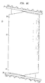
- FIG. 1 shows a vertebral body spacer in accordance with certain preferred embodiments of the present invention.
- the spacer 20 includes a main body 22 having a first endplate 24 secured to an upper end of the main body and a second endplate 26 secured to a lower end of the main body.
- the spacer 20 is preferably made of a biocompatible material, such as a polymeric material, titanium, or stainless steel. Preferred materials may also include titanium alloys or stainless steel alloys.
- main body 22 has a longitudinal axis designated A-A
- Main body 22 is preferably substantially cylindrical in shape and has an exterior surface that is coaxial with longitudinal axis A-A. In other preferred embodiments, main body 22 may be polygon-shaped in cross section.
- Main body 22 may have any geometric shape, such as the shape of an oval or ellipse.
- Main body 22 preferably has an upper end 28 with a first substantially concave-shaped socket 30 formed therein.
- the upper end 28 includes an upper edge 32 that surrounds the first concave socket 30.
- the upper edge 32 includes a first plane 34 and a second plane 36 that are angled relative to one another. The planes 34, 36 intersect at respective apexes 38A and 38B.
- Upper edge 32 also includes opposing first and second retaining clips 40A and 40B.
- First retaining clip 40A has an inwardly extending portion 42A and second retaining clip 40B has an inwardly extending projection 42B.
- the retaining clips 40A, 40B are designed to pass through retainer clip openings that extend through the endplates shown in FIG. 1 for securing the endplates to the respective upper and lower ends of main body 22.
- main body 22 also has a lower end 44 including a substantially concave socket 45 and lower edge 46 that is substantially similar in design and shape to the first socket 30 at upper end 28.
- the lower edge 46 has a first inclined plane 48 and a second inclined plane 50 angled relative to one another, the inclined planes intersecting at opposing retaining clips 54A and 54B that are designed to pass through the retaining clip apertures of the second endplate.
- Main body 22 includes a substantially cylindrical interior wall 53 defining a hollow space 55 that extends between the upper end cavity 30 and the lower end cavity 45.
- the interior wall 53 may be a flat surface or have any geometric shape defining a hollow space inside main body 22.
- the hollow space is adapted to receive bone growth material therein for facilitating fusion of the spacer 20 with vertebral bone.
- FIG. 3 shows a top view of the first endplate 24.
- First endplate 24 includes a central opening 56 surrounded by a peripheral flange 58.
- the peripheral flange 58 has an upper surface 60 and a lower surface 62 opposite the upper surface 60.
- the peripheral flange also includes a series of apertures 64A-C and 66A-C.
- First endplate 24 also includes retainer clip apertures 68A and 68B that extend between upper and lower surfaces 60, 62 of flange 58.
- Upper surface 60 also includes a plurality of teeth 70 for anchoring or biting into bone such as the face of a vertebral body.
- first endplate 24 also includes a projection 72 extending from an underside 62 thereof.
- the projection 72 surrounds central opening 56 and has an exterior surface 74 that is substantially curved or convex.
- the substantially convex 74 projection facilitates pivotal movement of the first and second endplates 24, 26 relative to main body 22 (FIG. 1) when the endplates are not under load.
- the vertebral body spacer 20 is assembled by juxtaposing the first endplate 24 with the upper end 28 of main body 22 and the second endplate 26 with the lower end 44 of main body 22.
- the opposing retaining clips 40A, 40B are passed through the retaining clip apertures 68A, 68B (FIG. 3) of first endplate 24.
- the regaining clips 40A, 40B are resilient so as to snap fit in place for pivotally connecting first endplate 24 with main upper end 28 of body 22.
- the convex exterior surface 74 of projection 72 is preferably in close engagement with first socket 30.
- first endplate 24 is able to pivot about apex 38A, with the engagement of convex exterior surface 74 and first socket 30 guiding movement of first endplate 24.
- First endplate 24 is able to pivot in a counterclockwise direction approximately 10° until underside surface 62 engages first plane upper edge 34 and in a clockwise direction approximately 10° until underside surface 62 engages second plane edge 36.
- the range of pivotal movement of first endplate 24 relative to upper end 28 of main body 22 is between 15° - 25°.
- second endplate 26 is secured to retaining clips 54A, 54B at lower end 44 of main body 22.
- Second endplate 26 is assembled with main body 22 by passing retaining clips 54A, 54B through retaining clip apertures (not shown) extending between upper surface 60' and underside surface 62'.
- retaining clips 54A, 54B through retaining clip apertures (not shown) extending between upper surface 60' and underside surface 62'.
- convex exterior surface 74' of projection 72' closely engages second socket 30' for guiding pivotal movement of second endplate 26 about apex 52A.
- Second endplate is pivotable approximately 10° in the counterclockwise direction until underside surface 62' engages second plane 50, and approximately 10° in the clockwise direction until underside surface 62' engages first plane 48.
- bone growth material (not shown) can be passed through the central openings of the first and second endplates 24, 26 for being disposed in hollow space 55.
- the bone growth material completely fills the hollow space 55 and extends beyond the upper and lower ends 28, 44 of main body 22.
- the bone growth material is disposed in the central openings of the endplates 24, 26 for facilitating fusion with opposing vertebral bodies.
- FIG. 6 shows a partially cut-away view of the vertebral body spacer 20 of FIG. 1.
- main body 22 includes upper end 28 and lower end 44 remote therefrom.
- the upper end 28 of main body 22 has a first concave socket 30 formed therein and the lower end 44 has a second concave socket 30' formed therein.
- the main body 22 is substantially hollow, with the hollow opening extending between first socket 30 and second socket 30'.
- FIG. 7A shows a fragmentary view of FIG. 6 before load is placed upon first endplate 24. Even though convex surface 74 of first endplate 24 is in direct contact with first socket 30, the first endplate remains free to pivot relative to first socket 30.
- FIG. 7B after load has been placed upon upper surface 60 of first endplate 24, the convex surface 74 is urged into closer engagement with first socket 30, thereby locking first endplate 24 in place and preventing further pivotal movement of first endplate 24 relative to main body 22.
- First endplate 24 remains locked from further pivotal movement so long as first endplate remains under load.
- the second endplate 26 (FIG. 5) is also locked from further pivotal movement when under load in a manner similar to that described above for the first endplate 24
- the above-described locking action can be attained without the need for additional parts such as locking screws that are typically required in prior art devices.
- FIGS. 8A-8C show the range of pivotal movement of the first and second endplates 24, 26 relative to main body 22.
- first endplate 24 rotates in a clockwise direction around apex 38A until underside surface 62 engages second plane 36.
- Second endplate 26 is pivotable about apex 52A until underside surface 62' engages second plane 50.
- FIG. 8B shows the vertebral body spacer 20 of FIG. 8A with first endplate 24A rotated in a fully clockwise orientation and second endplate 26 positioned equidistant between a fully clockwise rotation and a fully counterclockwise rotation.
- FIG. 8C shows the vertebral body spacer 20 of FIG. 8B with first endplate 24 fully rotated in a clockwise position and second endplate 26 fully rotated in a clockwise position.
- the vertebral body spacer 20 of the present invention will provide an effective spacer between end faces of vertebral bodies.
- the spacer 20 of the present invention may span a gap present after one or more discs or vertebral bodies have been removed.
- the teeth 70 of the first and second endplates 24, 26 are designed to bite into the bony end faces of the vertebral bodies for holding the spacer 20 in place.
- the end faces are free to pivot relative to the upper end 28 and lower end 44 of main body 22.
- the endplates are locked in place from further pivotal movement due to engagement of their convex exterior surfaces 74, 74' with the respective first and second sockets 30, 30'.
- only one of the ends of the main body may have a pivotable endplate connected thereto, while the other end may be rigid or unmovable.
Abstract
Description
- The present invention is related to orthopedic implants and is more particularly related to spinal implants.
- There have been many efforts directed to providing improved spinal implant devices. For example, U.S. Patent 5,534,029 to Shima discloses an articulated vertebral body spacer including a pair of upper and lower joint pieces inserted between opposing vertebrae. The lower joint piece includes a convex portion formed on a central portion of its upper surface and having a convex sliding contact surface, and a stopper surface surrounding the convex portion. The upper joint piece includes a concave portion formed on a central portion of its lower surface and having a concave sliding contact surface which is in sliding contact with the convex sliding contact surface, and an abutment surface that surrounds the concave portion and abuts against the stopper surface. A cavity for allowing the upper joint piece to pivot in response to movement of the opposing vertebral bodies is formed between the abutment surface and the stopper surface.
- DE 3529761 discloses in FIGS. 1A and 1B thereof a prosthesis for an intervertebral disc including two
plates 1 with a spacer disc 4 therebetween. The twoplates 1 each have a concave center and a flat annular rim 2 withspikes 3. The disc spacer 4 has a convex center and a flat rim with an annular groove 6. The prosthesis is used for spanning the gap between opposing vertebral faces remaining firmly in place while permitting natural movement of the spine. - U.S. Patent 4,997,432 to Keller discloses a prosthesis including two
stop plates 3 and a sliding body 4 arranged therebetween. The outer surfaces of thestop plates 3 have an essentially planar surface 5 provided with tooth-like projection 6 that penetrate into the vertebral bodies to fix thestop plates 3 securely to thevertebral bodies 1. The opposite side surfaces of thestop plates 3 include essentially spherical-shell-shaped recesses 7. The sliding core 4 has a spherical-shell-shaped projections 8 corresponding to the spherical-shell-shaped recesses 7. Thestop plates 3 are made of metal and the sliding body 4 is made of a synthetic material. - U.S. Patent 5,562,738 to Boyd et al. discloses an implant device 110 having an ellipsoidally-shaped ball 146 and socket 126 oriented so that their greatest lengths are disposed along a first axis transverse to the anterior and posterior ends 158 and 160 respectively and their shortest lengths are disposed along a second axis which is perpendicular to the first axis along surface 156. A first joint surface 136 is sloped away from socket 126 while a second joint surface 156 remains flat. The degree of slope determines the amount of relative rotation between joint surfaces 136 and 156 respectively, and the first joint surface 136 is sloped to provide for up to 5° of lateral bending in either direction, up to 5° of extension and up to 5° of Flexion.
- Finally, U.S. Patent 5,556,431 to Buttner-Janz discloses an intervertebral disc endoprosthesis that is inserted between two vertebrae and has a bottom plate and a top plate that are connected to vertebral endplates. Referring to FIG. 1, the device includes
prosthesis plates 1 and 2 andprosthesis core 3 cooperated via spherical surfaces 4. Thecore 3 has an edge rim 5 that limits its range of movement and insures, even under extreme conditions cohesion of the prosthesis. The endplate 6 of theprosthesis plates 1, 2 lie on the end surfaces of the vertebrae and are provided with teeth 7 which, under load, penetrate into the vertebrae and thus secure the prosthesis in situ. Bore holes 8 are arranged symmetrically on both side of the central plane, running from ventral to dorsal, of the vertebrae and in the area of the front edge of theprosthesis plates 1, 2 to receive bone screws 9. - In spite of the above-noted advances in the art, there remains a need for an improved vertebral body spacer having enhanced stabilization and bone fusion characteristics. There is also a need for a vertebral body spacer that may be readily packed with bone growth material for facilitating fusion of the spacer with vertebral bodies. In addition, there is a need for a vertebral body spacer that is capable of obtaining a locking effect without the need for additional components such as locking screws.
- In certain preferred embodiments of the present invention, a vertebral body spacer includes a main body having an upper end including a first concave socket and a lower end including a second concave socket A first endplate is secured to the upper end of the main body and includes an underside having a convex projection adapted to form a ball and socket arrangement with the first concave socket. A second endplate is secured to the lower end of the main body and includes an underside having a convex projection adapted to form a ball and socket arrangement with the second concave socket.
- In certain preferred embodiments, the upper end of the main body may include an upper edge defining first and second planes that are angled relative to one, and the lower end of the main body may include a lower edge defining first and second planes angled relative to one another. The first and second planes of the upper edge preferably intersect one another at an upper end apex and the first and second planes of the lower edge preferably intersect one another at a lower end apex.
- The upper apex desirably includes at least one retaining clip projecting therefrom for securing the first endplate to the upper end of the main body and the lower apex includes at least one retaining clip projecting therefrom for securing the second endplate to the lower end of the main body. In highly preferred embodiments, the upper apex includes a pair of retaining clips spaced from one another for pivotally securing the first endplate and the lower apex includes a pair of retaining clips spaced from one another for pivotally securing the second endplate. The first and second angled planes of the upper edge preferably limit pivotal movement of the first endplate and the first and second angled planes of the lower edge limit pivotal movement of the second endplate.
- In certain preferred embodiments, the first endplate includes an upper side having teeth for engaging bone, such as the face of a vertebral body, and the second endplate includes an upper side having teeth for engaging bone. The first endplate also preferably has a central opening and a peripheral flange surrounding the central opening, the peripheral flange having at least one opening adapted to facilitate bone fusion. The second endplate, which may be substantially similar in size and shape as the first endplate, also preferably has a central opening and a peripheral flange surrounding the central opening, the peripheral flange having at least one opening adapted to facilitate bone fusion.
- Each endplate preferably includes at least one retaining clip aperture adapted for receiving one of the retaining clips for securing the endplate with the main body.
- In certain preferred embodiments, the main body is elongated and has an outer surface that is curved. In other preferred embodiments, the main body is substantially cylindrical in shape. The main body may also be elliptical, or have any other geometric shape. In one particular preferred embodiment, the main body has a longitudinal axis and the first and second concave sockets are coaxial about the longitudinal axis. The first and second angled planes at the upper end of the main body form an angle of approximately 5-25 degrees, and more preferably an angle of approximately 10-20 degrees. The main body desirably has a cross-sectional diameter of approximately 10-30 mm, and the endplates have a diameter of approximately 30-50 mm. In other preferred embodiments, the endplates have a diameter of approximately 35-40 mm.
- The main body and the first and second endplates are desirably made of biocompatible materials, such as titanium, stainless steel, alloys and combinations thereof. The biocompatible material may also comprise polymeric materials.
- The central opening of the first endplate desirably provides communication between the first socket and an exterior of the spacer. The central opening of the second endplate desirably provides communication between the second socket and an exterior of the spacer.
- In operation, the spacer is positioned between the opposing faces of vertebrae. The endplates are pivotable when the spacer is in a first no-load state and are locked from pivotal movement when the spacer is in a second load state. Once pressure is applied to the endplates, the ball-and-socket joints are locked due to the blockage of the convex projections of the endplates in the concave sockets. After being positioned between two vertebrae, the endplates are desirably oriented for pivoting in a sagittal plane of a spine,
- In other preferred embodiments of the present invention, a vertebral body spacer includes a main body having an upper end and a lower end, the upper end having a first concave socket and an upper edge surrounding the first concave socket defining first and second planes angled relative to one another, the lower end having a second concave socket and a lower edge surrounding the second concave socket defining first and second planes angled relative to one another. The spacer also preferably includes a first endplate pivotally secured to the upper end of the main body for pivoting between the first and second planes of the upper edge, the first endplate including an underside having a convex projection adapted to engage the first concave socket. The spacer also preferably includes a second endplate pivotally secured to the lower end of the main body for pivoting between the first and second planes of the lower edge, the second endplate including an underside having a convex projection adapted to engage the second concave socket. The convex projections preferably form ball and socket joints with the respective first and second concave sockets.
- The upper edge desirably includes at least one retainer clip projecting therefrom for pivotally securing the first endplate to the main body, and the first endplate desirably includes at least one retainer clip aperture extending therethrough, the at least one retainer clip being passable therethrough for pivotally securing the first endplate to the main body, The first endplate preferably includes a series of apertures extending therethrough for receiving bone growth material and facilitating spinal fusion.
- The lower edge desirably includes at least one retainer clip projecting therefrom for pivotally securing the second endplate to the main body, and the second endplate desirably includes at least one retainer clip aperture extending therethrough, the at least one retainer clip being passable therethrough for pivotally securing the second endplate to the main body. The second endplate preferably includes a series of apertures extending therethrough for receiving bone growth material and facilitating spinal fusion.
- These and other preferred embodiments of the present invention will be described in more detail below.
-
- FIG. 1 shows a perspective view of a vertebral body spacer including a main body, a first endplate and a second endplate.
- FIG. 2 shows a perspective view of the main body of FIG. 1 with the first and second endplates detached from the main body.
- FIG. 3 shows a top view of the first endplate shown in FIG. 1.
- FIG. 4 shows an underside view of the endplate shown in FIG. 3.
- FIG. 5 shows a side elevation view of the vertebral body spacer of FIG. 1.
- FIG. 6 shows a partial cut away view of the vertebral body spacer of FIG. 5.
- FIG. 7A shows the first endplate of FIG. 1 under a no-load condition.
- FIG. 7B shows the first endplate of FIG: 7A under a load condition.
- FIG. 8A-8C show the vertebral body spacer of FIG. 5 with the first and second endplates pivoted to various angles relative to the main body.
-
- FIG. 1 shows a vertebral body spacer in accordance with certain preferred embodiments of the present invention. The
spacer 20 includes amain body 22 having afirst endplate 24 secured to an upper end of the main body and asecond endplate 26 secured to a lower end of the main body. Thespacer 20 is preferably made of a biocompatible material, such as a polymeric material, titanium, or stainless steel. Preferred materials may also include titanium alloys or stainless steel alloys. Referring to FIG. 2, in certain preferred embodiments,main body 22 has a longitudinal axis designatedA-A Main body 22 is preferably substantially cylindrical in shape and has an exterior surface that is coaxial with longitudinal axis A-A. In other preferred embodiments,main body 22 may be polygon-shaped in cross section.Main body 22 may have any geometric shape, such as the shape of an oval or ellipse.Main body 22 preferably has anupper end 28 with a first substantially concave-shapedsocket 30 formed therein. Theupper end 28 includes an upper edge 32 that surrounds the firstconcave socket 30. The upper edge 32 includes afirst plane 34 and asecond plane 36 that are angled relative to one another. Theplanes respective apexes clip 40A has an inwardly extendingportion 42A andsecond retaining clip 40B has an inwardly extending projection 42B. As will be described in more detail below, the retainingclips main body 22. - Referring to FIG. 2,
main body 22 also has alower end 44 including a substantiallyconcave socket 45 andlower edge 46 that is substantially similar in design and shape to thefirst socket 30 atupper end 28. Thelower edge 46 has a firstinclined plane 48 and a secondinclined plane 50 angled relative to one another, the inclined planes intersecting at opposing retainingclips 54A and 54B that are designed to pass through the retaining clip apertures of the second endplate.Main body 22 includes a substantially cylindricalinterior wall 53 defining ahollow space 55 that extends between theupper end cavity 30 and thelower end cavity 45. In other embodiments, theinterior wall 53 may be a flat surface or have any geometric shape defining a hollow space insidemain body 22. As will be described in more detail below, the hollow space is adapted to receive bone growth material therein for facilitating fusion of thespacer 20 with vertebral bone. - FIG. 3 shows a top view of the
first endplate 24.First endplate 24 includes acentral opening 56 surrounded by aperipheral flange 58. Referring to FIGS. 3 and 4, theperipheral flange 58 has anupper surface 60 and alower surface 62 opposite theupper surface 60. The peripheral flange also includes a series ofapertures 64A-C and 66A-C. First endplate 24 also includesretainer clip apertures 68A and 68B that extend between upper andlower surfaces flange 58.Upper surface 60 also includes a plurality ofteeth 70 for anchoring or biting into bone such as the face of a vertebral body. - Referring to FIG. 4,
first endplate 24 also includes aprojection 72 extending from anunderside 62 thereof. Theprojection 72 surroundscentral opening 56 and has anexterior surface 74 that is substantially curved or convex. As will be described in more detail below, the substantially convex 74 projection facilitates pivotal movement of the first andsecond endplates - Referring to FIGS. 1 and 5, the
vertebral body spacer 20 is assembled by juxtaposing thefirst endplate 24 with theupper end 28 ofmain body 22 and thesecond endplate 26 with thelower end 44 ofmain body 22. During assembly, the opposing retainingclips clip apertures 68A, 68B (FIG. 3) offirst endplate 24. In certain preferred embodiments, the regainingclips first endplate 24 with mainupper end 28 ofbody 22. After thefirst endplate 24 has been snap fit in place, theconvex exterior surface 74 ofprojection 72 is preferably in close engagement withfirst socket 30. As such,first endplate 24 is able to pivot aboutapex 38A, with the engagement of convexexterior surface 74 andfirst socket 30 guiding movement offirst endplate 24.First endplate 24 is able to pivot in a counterclockwise direction approximately 10° untilunderside surface 62 engages first planeupper edge 34 and in a clockwise direction approximately 10° untilunderside surface 62 engagessecond plane edge 36. Thus, the range of pivotal movement offirst endplate 24 relative toupper end 28 ofmain body 22 is between 15° - 25°. - In a similar fashion,
second endplate 26 is secured to retainingclips 54A, 54B atlower end 44 ofmain body 22.Second endplate 26 is assembled withmain body 22 by passing retainingclips 54A, 54B through retaining clip apertures (not shown) extending between upper surface 60' and underside surface 62'. Assecond endplate 26 is assembled withlower end 44 ofmain body 22, convex exterior surface 74' of projection 72' closely engages second socket 30' for guiding pivotal movement ofsecond endplate 26 aboutapex 52A. - Second endplate is pivotable approximately 10° in the counterclockwise direction until underside surface 62' engages
second plane 50, and approximately 10° in the clockwise direction until underside surface 62' engagesfirst plane 48. - Referring to FIG. 5, bone growth material (not shown) can be passed through the central openings of the first and
second endplates hollow space 55. In certain preferred embodiments, the bone growth material completely fills thehollow space 55 and extends beyond the upper and lower ends 28, 44 ofmain body 22. In more preferred embodiments, the bone growth material is disposed in the central openings of theendplates - FIG. 6 shows a partially cut-away view of the
vertebral body spacer 20 of FIG. 1. As described above,main body 22 includesupper end 28 andlower end 44 remote therefrom. Theupper end 28 ofmain body 22 has a firstconcave socket 30 formed therein and thelower end 44 has a second concave socket 30' formed therein. In preferred embodiments, themain body 22 is substantially hollow, with the hollow opening extending betweenfirst socket 30 and second socket 30'. After first andsecond endplates main body 22, the endplates are free to pivot relative to main body so long as little or no load is placed upon the endplates. When the endplates are placed under load, however, the exterior surfaces 74, 74' of the projections are forced into close engagement with thesockets - FIG. 7A shows a fragmentary view of FIG. 6 before load is placed upon
first endplate 24. Even thoughconvex surface 74 offirst endplate 24 is in direct contact withfirst socket 30, the first endplate remains free to pivot relative tofirst socket 30. Referring to FIG. 7B, after load has been placed uponupper surface 60 offirst endplate 24, theconvex surface 74 is urged into closer engagement withfirst socket 30, thereby lockingfirst endplate 24 in place and preventing further pivotal movement offirst endplate 24 relative tomain body 22. Although not limited by any particular theory of operation, it is believed that once load is placed uponfirst endplate 24, friction forces lock first endplate from further pivotal movement relative tomain body 22.First endplate 24 remains locked from further pivotal movement so long as first endplate remains under load. The second endplate 26 (FIG. 5) is also locked from further pivotal movement when under load in a manner similar to that described above for thefirst endplate 24 The above-described locking action can be attained without the need for additional parts such as locking screws that are typically required in prior art devices. - Once load has been removed from one of the
endplates main body 22 so long as it is not under load. Once load is reapplied, however, the endplate will once again be locked in place against further pivotal movement. Such locking and unlocking action will take place repeatedly during the life of the vertebral body spacer of the present invention. - FIGS. 8A-8C show the range of pivotal movement of the first and
second endplates main body 22. In FIG. 8Afirst endplate 24 rotates in a clockwise direction aroundapex 38A untilunderside surface 62 engagessecond plane 36.Second endplate 26 is pivotable about apex 52A until underside surface 62' engagessecond plane 50. - FIG. 8B shows the
vertebral body spacer 20 of FIG. 8A with first endplate 24A rotated in a fully clockwise orientation andsecond endplate 26 positioned equidistant between a fully clockwise rotation and a fully counterclockwise rotation. FIG. 8C shows thevertebral body spacer 20 of FIG. 8B withfirst endplate 24 fully rotated in a clockwise position andsecond endplate 26 fully rotated in a clockwise position. - Although not limited by any particular theory of operation, it is believed that the
vertebral body spacer 20 of the present invention will provide an effective spacer between end faces of vertebral bodies. Thespacer 20 of the present invention may span a gap present after one or more discs or vertebral bodies have been removed. Theteeth 70 of the first andsecond endplates spacer 20 in place. In a first no-load state, when no load is applied to the end faces 24, 26, the end faces are free to pivot relative to theupper end 28 andlower end 44 ofmain body 22. Once a load is exerted upon eitherendplate second sockets 30, 30'. - In other preferred embodiments, only one of the ends of the main body may have a pivotable endplate connected thereto, while the other end may be rigid or unmovable.
- Although the invention herein has been described with reference to particular embodiments, it is to be understood that these embodiments are merely illustrative of the principles and applications of the present invention. It is therefore contemplated that numerous modifications may be made to the illustrated embodiments and that other arrangements may be made without departing from the spirit and scope of the present invention as defined by the appended claims.
Claims (33)
- A vertebral body spacer comprising:a main body having an upper end including a first concave socket and a lower end including a second concave socket;a first endplate secured to said upper end of said main body, wherein said first endplate includes an underside having a convex projection adapted to form a ball and socket arrangement with said first concave socket; anda second endplate secured to said lower end of said main body, wherein said second endplate includes an underside having a convex projection adapted to form a ball and socket arrangement with said second concave socket.
- The spacer as claimed in claim 1, wherein said upper end includes an upper edge defining first and second planes angled relative to one and said lower end includes a lower edge defining first and second planes angled relative to one another.
- The spacer as claimed in claim 2, wherein said first and second planes of said upper edge intersect one another at an upper end apex and said first and second planes of said lower edge intersect one another an a lower end apex.
- The spacer as claimed in claim 3, wherein said upper apex includes at least one retaining clip projecting therefrom for securing said first endplate to said upper end of said main body and said lower apex includes at least one retaining clip projecting therefrom for securing said second endplate to said lower end of said main body.
- The spacer as claimed in claim 4, wherein said upper apex includes a pair of retaining clips spaced from one another for securing said first endplate and said lower apex includes a pair of retaining clips spaced from one another for securing said second endplate.
- The spacer as claimed in claim 4, wherein said first and second angled planes of said upper edge limit pivotal movement of said first endplate and said first and second angled planes of said lower edge limit pivotal movement of said second endplate.
- The spacer as claimed in claim 1, wherein said first endplate includes an upper side having teeth for engaging bone and said second endplate includes an upper side having teeth for engaging bone.
- The spacer as claimed in claim 7, wherein said first endplate has a central opening and a peripheral flange surrounding said central opening, and wherein said peripheral flange has at least one opening adapted to receive bone growth materials
- The spacer as claimed in claim 8, wherein said second endplate has a central opening and a peripheral flange surrounding said central opening, and wherein said peripheral flange has at least one opening adapted to receive bone growth material.
- The spacer as claimed in claim 4, wherein each said endplate includes at least one retaining clip aperture adapted for receiving one of said retaining clips for securing said endplate with said main body.
- The spacer as claimed in claim 1, wherein each said endplate has teeth adapted for anchoring said spacer into bone.
- The spacer as claimed in claim 1, wherein said main body is elongated and has an at least partially curved outer surface.
- The spacer as claimed in claim 1, wherein said main body has a longitudinal axis and said first and second concave sockets are coaxial about said longitudinal axis.
- The spacer as claimed in claim 1, wherein said main body and said first and second endplates are made of biocompatible material.
- The spacer as claimed in claim 14, wherein said biocompatible material is selected from the group consisting of titanium, stainless steel, alloys and combinations thereof.
- The spacer as claimed in claim 14, wherein said biocompatible material comprises polymeric materials.
- The spacer as claimed in claim 9, wherein said central opening of said first endplate provides communication between said first socket and an exterior of said spacer.
- The spacer as claimed in claim 9, wherein said central opening of said second endplate provides communication between said second socket and an exterior of said spacer
- The spacer as claimed in claim 1, wherein said endplates are pivotable when said spacer is in a first no-load state and are locked from pivotal movement when said spacer is in a second load state.
- The spacer as claimed in claim 2, wherein said first and second angled planes at said upper end of said main body form an angle of approximately 5-25 degrees.
- The spacer as claimed in claim 20, wherein said first and second angled planes at said upper end of said main body form an angle of approximately 10-20 degrees.
- The spacer as claimed in claim 1, wherein said endplates are oriented for pivoting in a sagittal plane of a spine.
- The spacer as claimed in claim 1, wherein said main body has a cross-sectional diameter of approximately 10-30 mm.
- The spacer as claimed in claim 1, wherein said endplates have a diameter of approximately 30-50 mm.
- The spacer as claimed in claim 24, wherein said endplates have a diameter of approximately 35-40 mm.
- A vertebral body spacer comprising:a main body including an upper end and a lower end, said upper end having a first concave socket and an upper edge surrounding said first concave socket defining first and second planes angled relative to one another, said lower end having a second concave socket and a lower edge surrounding said second concave socket defining first and second planes angled relative to one another;a first endplate pivotally secured to said upper end of said main body for pivoting between said first and second planes of said upper edge, said first endplate including an underside having a convex projection adapted to engage said first concave socket;a second endplate pivotally secured to said lower end of said main body for pivoting between said first and second planes of said lower edge, said second endplate including an underside having a convex projection adapted to engage said second concave socket.
- The spacer as claimed in claim 26, wherein said convex projections form ball and socket joints with the respective said first and second concave sockets.
- The spacer as claimed in claim 26, wherein said upper edge includes at least one retainer clip projecting therefrom for pivotally securing said first endplate to said main body.
- The spacer as claimed in claim 28, wherein said first endplate includes at least one retainer clip aperture extending therethrough, and wherein said at least one retainer clip is passable therethrough.
- The spacer as claimed in claim 28, wherein said first endplate includes a series of apertures extending therethrough for receiving bone growth material and facilitating spinal fusion.
- The spacer as claimed in claim 26, wherein said lower edge includes at least one retainer clip projecting therefrom for pivotally securing said second endplate to said main body.
- The spacer as claimed in claim 31, wherein said second endplate includes at least one retainer clip aperture extending therethrough, and wherein said at least one retainer clip is passable therethrough.
- The spacer as claimed in claim 32, wherein said second endplate includes a series of apertures extending therethrough for receiving bone growth material and facilitating spinal fusion.
Applications Claiming Priority (2)
| Application Number | Priority Date | Filing Date | Title |
|---|---|---|---|
| US99693 | 2002-03-15 | ||
| US10/099,693 US6808538B2 (en) | 2002-03-15 | 2002-03-15 | Vertebral body spacer having variable wedged endplates |
Publications (3)
| Publication Number | Publication Date |
|---|---|
| EP1346709A2 true EP1346709A2 (en) | 2003-09-24 |
| EP1346709A3 EP1346709A3 (en) | 2003-11-19 |
| EP1346709B1 EP1346709B1 (en) | 2005-12-07 |
Family
ID=27788324
Family Applications (1)
| Application Number | Title | Priority Date | Filing Date |
|---|---|---|---|
| EP03290628A Expired - Lifetime EP1346709B1 (en) | 2002-03-15 | 2003-03-13 | Vertebral body spacer having variable wedged endplates |
Country Status (5)
| Country | Link |
|---|---|
| US (1) | US6808538B2 (en) |
| EP (1) | EP1346709B1 (en) |
| JP (1) | JP4050640B2 (en) |
| AT (1) | ATE311837T1 (en) |
| DE (1) | DE60302595T2 (en) |
Cited By (7)
| Publication number | Priority date | Publication date | Assignee | Title |
|---|---|---|---|---|
| EP1398008A1 (en) | 2002-09-12 | 2004-03-17 | BIEDERMANN MOTECH GmbH | Spacer for vertebrae or spinal discs |
| EP1684674A2 (en) * | 2003-10-20 | 2006-08-02 | Blackstone Medical, Inc. | Vertebral body replacement apparatus and method |
| DE102005022921B3 (en) * | 2005-05-19 | 2007-01-25 | Aesculap Ag & Co. Kg | Vertebral body replacement implant |
| EP2161008A3 (en) * | 2003-05-27 | 2010-06-30 | Spinalmotion, Inc. | Prosthetic disc for intervertebral insertion |
| US7963994B2 (en) | 2002-09-12 | 2011-06-21 | Biedermann Motech Gmbh | Intervertebral disk prosthesis |
| US8512406B2 (en) | 2002-03-21 | 2013-08-20 | Warsaw Orthopedic, Inc. | Vertebral body and disc space replacement devices |
| EP3288500A4 (en) * | 2015-04-27 | 2019-01-02 | Corenman, Donald, Steven | Biological disc graft and method for relief of lower back pain and joint pain |
Families Citing this family (134)
| Publication number | Priority date | Publication date | Assignee | Title |
|---|---|---|---|---|
| US7959652B2 (en) * | 2005-04-18 | 2011-06-14 | Kyphon Sarl | Interspinous process implant having deployable wings and method of implantation |
| US20080215058A1 (en) | 1997-01-02 | 2008-09-04 | Zucherman James F | Spine distraction implant and method |
| US6068630A (en) | 1997-01-02 | 2000-05-30 | St. Francis Medical Technologies, Inc. | Spine distraction implant |
| US20020169507A1 (en) | 2000-12-14 | 2002-11-14 | David Malone | Interbody spine fusion cage |
| US7169182B2 (en) * | 2001-07-16 | 2007-01-30 | Spinecore, Inc. | Implanting an artificial intervertebral disc |
| US6673113B2 (en) | 2001-10-18 | 2004-01-06 | Spinecore, Inc. | Intervertebral spacer device having arch shaped spring elements |
| US7223291B2 (en) * | 2001-07-16 | 2007-05-29 | Spinecore, Inc. | Intervertebral spacer device having engagement hole pairs for manipulation using a surgical tool |
| US6989032B2 (en) * | 2001-07-16 | 2006-01-24 | Spinecore, Inc. | Artificial intervertebral disc |
| US20070198092A1 (en) * | 2001-07-16 | 2007-08-23 | Spinecore, Inc. | System for inserting artificial intervertebral discs |
| US7771477B2 (en) | 2001-10-01 | 2010-08-10 | Spinecore, Inc. | Intervertebral spacer device utilizing a belleville washer having radially spaced concentric grooves |
| US7309358B2 (en) * | 2002-03-21 | 2007-12-18 | Warsaw Orthopedic, Inc. | Vertebral body and disc space replacement devices |
| US6758862B2 (en) * | 2002-03-21 | 2004-07-06 | Sdgi Holdings, Inc. | Vertebral body and disc space replacement devices |
| US8147548B2 (en) | 2005-03-21 | 2012-04-03 | Kyphon Sarl | Interspinous process implant having a thread-shaped wing and method of implantation |
| EP1555966A4 (en) * | 2002-10-29 | 2011-03-16 | Spinecore Inc | Instrumentation, methods, and features for use in implanting an artificial intervertebral disc |
| US7549999B2 (en) | 2003-05-22 | 2009-06-23 | Kyphon Sarl | Interspinous process distraction implant and method of implantation |
| FR2850563B1 (en) * | 2003-02-05 | 2005-11-04 | Scient X | VERTEBRAL REPLACEMENT IMPLANT AND DISTRACTION APPARATUS FOR IMPLANT PLACEMENT |
| DE10311477A1 (en) * | 2003-03-15 | 2004-09-23 | Ulrich Gmbh & Co. Kg | Implant to be inserted between the vertebral body of the spine |
| US7918876B2 (en) | 2003-03-24 | 2011-04-05 | Theken Spine, Llc | Spinal implant adjustment device |
| US7419505B2 (en) * | 2003-04-22 | 2008-09-02 | Fleischmann Lewis W | Collapsible, rotatable, and tiltable hydraulic spinal disc prosthesis system with selectable modular components |
| EP1501453B2 (en) | 2003-05-14 | 2010-06-30 | Kilian Kraus | Height-adjustable implant to be inserted between vertebral bodies and corresponding handling tool |
| FR2858546B1 (en) | 2003-08-04 | 2006-04-28 | Spine Next Sa | INTERVERTEBRAL DISC PROSTHESIS |
| US7794465B2 (en) * | 2003-09-10 | 2010-09-14 | Warsaw Orthopedic, Inc. | Artificial spinal discs and associated implantation instruments and methods |
| US7766914B2 (en) * | 2003-09-10 | 2010-08-03 | Warsaw Orthopedic, Inc. | Adjustable drill guide |
| ATE390101T1 (en) | 2003-11-18 | 2008-04-15 | Zimmer Gmbh | DISC IMPLANT |
| DE10357926B3 (en) | 2003-12-11 | 2005-09-01 | Deltacor Gmbh | Length adjustable spinal implant |
| GB0401362D0 (en) * | 2004-01-22 | 2004-02-25 | Depuy Int Ltd | Vertebral fusion parts, devices and methods |
| JP4382092B2 (en) * | 2004-05-17 | 2009-12-09 | ウリドル スパイン ヘルス インスティチュート シーオー. | Intervertebral insert |
| EP1639969A1 (en) * | 2004-09-23 | 2006-03-29 | Cervitech, Inc. | Intravertebral prosthesis for bridging a vertebrae |
| EP1639968A1 (en) * | 2004-09-23 | 2006-03-29 | Cervitech, Inc. | Implant with a part to be inserted and anchored in a bone cavity |
| US8097018B2 (en) | 2005-02-17 | 2012-01-17 | Kyphon Sarl | Percutaneous spinal implants and methods |
| US8034080B2 (en) | 2005-02-17 | 2011-10-11 | Kyphon Sarl | Percutaneous spinal implants and methods |
| US8100943B2 (en) | 2005-02-17 | 2012-01-24 | Kyphon Sarl | Percutaneous spinal implants and methods |
| US20070276493A1 (en) | 2005-02-17 | 2007-11-29 | Malandain Hugues F | Percutaneous spinal implants and methods |
| US8157841B2 (en) | 2005-02-17 | 2012-04-17 | Kyphon Sarl | Percutaneous spinal implants and methods |
| US9456907B1 (en) | 2005-03-24 | 2016-10-04 | Igip, Llc | Extendable spinal implant |
| US8986383B2 (en) * | 2005-03-24 | 2015-03-24 | Igip, Llc | End cap and connector for a spinal implant |
| WO2006104722A2 (en) * | 2005-03-24 | 2006-10-05 | Accelerated Innovation, Llc | Intervertebral disc replacement device |
| US7435261B1 (en) * | 2005-03-24 | 2008-10-14 | Frank Castro | Spinal implant and method of using spinal implant |
| US8246683B2 (en) * | 2005-03-24 | 2012-08-21 | Cardinal Spine, Llc | Spinal implant |
| US8361149B2 (en) * | 2005-03-24 | 2013-01-29 | Cardinal Spine, Llc | Wedge-like spinal implant |
| US8673006B2 (en) * | 2005-03-24 | 2014-03-18 | Igip, Llc | Spinal implant |
| US8226718B2 (en) | 2005-03-24 | 2012-07-24 | Cardinal Spine, Llc | Spinal implant and method of using spinal implant |
| US7811327B2 (en) * | 2005-04-21 | 2010-10-12 | Globus Medical Inc. | Expandable vertebral prosthesis |
| US8551176B2 (en) * | 2005-05-06 | 2013-10-08 | Titan Spine, Llc | Spinal implant having a passage for enhancing contact between bone graft material and cortical endplate bone |
| US8758442B2 (en) | 2005-05-06 | 2014-06-24 | Titan Spine, Llc | Composite implants having integration surfaces composed of a regular repeating pattern |
| US8562684B2 (en) * | 2005-05-06 | 2013-10-22 | Titan Spine, Llc | Endplate-preserving spinal implant with an integration plate having a roughened surface topography |
| US11096796B2 (en) | 2005-05-06 | 2021-08-24 | Titan Spine, Llc | Interbody spinal implant having a roughened surface topography on one or more internal surfaces |
| US8585765B2 (en) | 2005-05-06 | 2013-11-19 | Titan Spine, Llc | Endplate-preserving spinal implant having a raised expulsion-resistant edge |
| US8585766B2 (en) * | 2005-05-06 | 2013-11-19 | Titan Spine, Llc | Endplate-preserving spinal implant with an integration plate having durable connectors |
| US8992622B2 (en) | 2005-05-06 | 2015-03-31 | Titan Spine, Llc | Interbody spinal implant having a roughened surface topography |
| US8545568B2 (en) | 2005-05-06 | 2013-10-01 | Titan Spine, Llc | Method of using instruments and interbody spinal implants to enhance distraction |
| US9168147B2 (en) | 2005-05-06 | 2015-10-27 | Titan Spine, Llc | Self-deploying locking screw retention device |
| US8585767B2 (en) * | 2005-05-06 | 2013-11-19 | Titan Spine, Llc | Endplate-preserving spinal implant with an integration plate having durable connectors |
| US20120312779A1 (en) | 2005-05-06 | 2012-12-13 | Titian Spine, LLC | Methods for manufacturing implants having integration surfaces |
| US8562685B2 (en) * | 2005-05-06 | 2013-10-22 | Titan Spine, Llc | Spinal implant and integration plate for optimizing vertebral endplate contact load-bearing edges |
| US8814939B2 (en) | 2005-05-06 | 2014-08-26 | Titan Spine, Llc | Implants having three distinct surfaces |
| US9125756B2 (en) | 2005-05-06 | 2015-09-08 | Titan Spine, Llc | Processes for producing regular repeating patterns on surfaces of interbody devices |
| US8591590B2 (en) | 2005-05-06 | 2013-11-26 | Titan Spine, Llc | Spinal implant having a transverse aperture |
| US8262737B2 (en) | 2005-05-06 | 2012-09-11 | Titan Spine, Llc | Composite interbody spinal implant having openings of predetermined size and shape |
| US8617248B2 (en) | 2005-05-06 | 2013-12-31 | Titan Spine, Llc | Spinal implant having variable ratios of the integration surface area to the axial passage area |
| US8758443B2 (en) | 2005-05-06 | 2014-06-24 | Titan Spine, Llc | Implants with integration surfaces having regular repeating surface patterns |
| US8435302B2 (en) | 2005-05-06 | 2013-05-07 | Titan Spine, Llc | Instruments and interbody spinal implants enhancing disc space distraction |
| US7674294B2 (en) * | 2005-12-01 | 2010-03-09 | Warsaw Orthopedic, Inc. | End device for a vertebral implant |
| EP1959870B1 (en) * | 2005-12-08 | 2009-07-08 | FBCdevice ApS | Disc implant |
| US8083795B2 (en) | 2006-01-18 | 2011-12-27 | Warsaw Orthopedic, Inc. | Intervertebral prosthetic device for spinal stabilization and method of manufacturing same |
| US20070270960A1 (en) * | 2006-04-24 | 2007-11-22 | Sdgi Holdings, Inc. | Extendable anchor in a vertebral implant and methods of use |
| US8118844B2 (en) | 2006-04-24 | 2012-02-21 | Warsaw Orthopedic, Inc. | Expandable device for insertion between anatomical structures and a procedure utilizing same |
| US8657882B2 (en) * | 2006-04-24 | 2014-02-25 | Warsaw Orthopedic, Inc. | Expandable intervertebral devices and methods of use |
| US8187331B2 (en) * | 2006-04-27 | 2012-05-29 | Warsaw Orthopedic, Inc. | Expandable vertebral implant and methods of use |
| US7794501B2 (en) * | 2006-04-27 | 2010-09-14 | Wasaw Orthopedic, Inc. | Expandable intervertebral spacers and methods of use |
| US7708779B2 (en) * | 2006-05-01 | 2010-05-04 | Warsaw Orthopedic, Inc. | Expandable intervertebral spacers and methods of use |
| US8016886B2 (en) | 2006-07-18 | 2011-09-13 | Altus Partners, Llc | Intervertebral disc replacement device |
| US7862618B2 (en) * | 2006-07-19 | 2011-01-04 | Warsaw Orthopedic, Inc. | Expandable vertebral body implants and methods of use |
| US7815683B2 (en) | 2006-10-16 | 2010-10-19 | Warsaw Orthopedic, Inc. | Implants with helical supports and methods of use for spacing vertebral members |
| US8097019B2 (en) | 2006-10-24 | 2012-01-17 | Kyphon Sarl | Systems and methods for in situ assembly of an interspinous process distraction implant |
| FR2908035B1 (en) | 2006-11-08 | 2009-05-01 | Jean Taylor | INTEREPINE IMPLANT |
| ES2666455T3 (en) * | 2007-03-07 | 2018-05-04 | Ulrich Gmbh & Co. Kg | Intervertebral implant with elastic component |
| AU2008224951A1 (en) | 2007-03-13 | 2008-09-18 | Synthes Gmbh | Adjustable intervertebral implant |
| WO2008121312A2 (en) * | 2007-03-29 | 2008-10-09 | Life Spine, Inc. | Height adjustable spinal prostheses |
| US20080262621A1 (en) * | 2007-04-17 | 2008-10-23 | K2M, Inc. | I-beam spacer |
| WO2009005819A1 (en) * | 2007-07-03 | 2009-01-08 | Scribner Robert M | Mobile spinal fusion implant |
| US20090062917A1 (en) * | 2007-08-27 | 2009-03-05 | Foley Kevin T | Spinal interbody replacement devices |
| US8852280B2 (en) | 2007-09-27 | 2014-10-07 | Warsaw Orthopedic, Inc. | Intervertebral implant |
| US9101410B1 (en) * | 2007-10-24 | 2015-08-11 | Robert E. Urrea | Facet joint fusion device and method for using same |
| US8142441B2 (en) * | 2008-10-16 | 2012-03-27 | Aesculap Implant Systems, Llc | Surgical instrument and method of use for inserting an implant between two bones |
| US8591587B2 (en) | 2007-10-30 | 2013-11-26 | Aesculap Implant Systems, Llc | Vertebral body replacement device and method for use to maintain a space between two vertebral bodies within a spine |
| US8182537B2 (en) | 2007-10-30 | 2012-05-22 | Aesculap Implant Systems, Llc | Vertebral body replacement device and method for use to maintain a space between two vertebral bodies within a spine |
| US8241363B2 (en) | 2007-12-19 | 2012-08-14 | Depuy Spine, Inc. | Expandable corpectomy spinal fusion cage |
| US8241294B2 (en) | 2007-12-19 | 2012-08-14 | Depuy Spine, Inc. | Instruments for expandable corpectomy spinal fusion cage |
| US8105358B2 (en) | 2008-02-04 | 2012-01-31 | Kyphon Sarl | Medical implants and methods |
| US8114136B2 (en) | 2008-03-18 | 2012-02-14 | Warsaw Orthopedic, Inc. | Implants and methods for inter-spinous process dynamic stabilization of a spinal motion segment |
| US8323292B2 (en) * | 2008-12-15 | 2012-12-04 | Spinecore, Inc. | Adjustable pin drill guide and methods therefor |
| US8721723B2 (en) * | 2009-01-12 | 2014-05-13 | Globus Medical, Inc. | Expandable vertebral prosthesis |
| US8142435B2 (en) | 2009-02-19 | 2012-03-27 | Aesculap Implant Systems, Llc | Multi-functional surgical instrument and method of use for inserting an implant between two bones |
| US8876905B2 (en) | 2009-04-29 | 2014-11-04 | DePuy Synthes Products, LLC | Minimally invasive corpectomy cage and instrument |
| US8372117B2 (en) | 2009-06-05 | 2013-02-12 | Kyphon Sarl | Multi-level interspinous implants and methods of use |
| US8202321B2 (en) * | 2009-06-17 | 2012-06-19 | Ulrich Gmbh & Co. Kg | Implant |
| EP2349112B1 (en) * | 2009-06-17 | 2014-07-23 | Ulrich GmbH & Co. KG | Implant |
| US8211178B2 (en) | 2009-06-18 | 2012-07-03 | Warsaw Orthopedic | Intervertebral implant with a pivoting end cap |
| US9095444B2 (en) | 2009-07-24 | 2015-08-04 | Warsaw Orthopedic, Inc. | Implant with an interference fit fastener |
| CN101627931B (en) * | 2009-08-06 | 2010-12-01 | 雷伟 | Artificial cervical complex joint |
| WO2011060071A1 (en) * | 2009-11-10 | 2011-05-19 | Medivest, Llc | Tissue spacer implant, implant tool, and methods of use thereof |
| US8317831B2 (en) | 2010-01-13 | 2012-11-27 | Kyphon Sarl | Interspinous process spacer diagnostic balloon catheter and methods of use |
| US8114132B2 (en) | 2010-01-13 | 2012-02-14 | Kyphon Sarl | Dynamic interspinous process device |
| US8147526B2 (en) | 2010-02-26 | 2012-04-03 | Kyphon Sarl | Interspinous process spacer diagnostic parallel balloon catheter and methods of use |
| US8591585B2 (en) | 2010-04-12 | 2013-11-26 | Globus Medical, Inc. | Expandable vertebral implant |
| US8282683B2 (en) * | 2010-04-12 | 2012-10-09 | Globus Medical, Inc. | Expandable vertebral implant |
| US8870880B2 (en) | 2010-04-12 | 2014-10-28 | Globus Medical, Inc. | Angling inserter tool for expandable vertebral implant |
| US20120016478A1 (en) * | 2010-07-15 | 2012-01-19 | Warsaw Orthopedic, Inc. | Intervertebral implant with multi-piece end cap |
| US9402734B2 (en) * | 2010-07-30 | 2016-08-02 | Igip, Llc | Spacer for spinal implant |
| US20120109302A1 (en) * | 2010-10-27 | 2012-05-03 | Warsaw Orthopedic | Medical implant and method for photodynamic therpy |
| US20120116457A1 (en) * | 2010-11-06 | 2012-05-10 | Limited Liability Company; | Stabilizer for assisting stabilization of a spinal implant and method of using the stabilizer |
| US9358122B2 (en) | 2011-01-07 | 2016-06-07 | K2M, Inc. | Interbody spacer |
| US8377140B2 (en) | 2011-01-12 | 2013-02-19 | Ebi, Llc | Expandable spinal implant device |
| US8740980B2 (en) | 2011-01-27 | 2014-06-03 | Warsaw Orthopedic, Inc. | Expandable medical implant |
| US8454694B2 (en) | 2011-03-03 | 2013-06-04 | Warsaw Orthopedic, Inc. | Interbody device and plate for spinal stabilization and instruments for positioning same |
| US9700425B1 (en) | 2011-03-20 | 2017-07-11 | Nuvasive, Inc. | Vertebral body replacement and insertion methods |
| US8425606B2 (en) * | 2011-06-21 | 2013-04-23 | John A. Cowan | Method and implant device for grafting adjacent vertebral bodies |
| US9468537B2 (en) * | 2011-06-21 | 2016-10-18 | Globus Medical, Inc. | Method and implant device for grafting adjacent vertebral bodies |
| US8992619B2 (en) | 2011-11-01 | 2015-03-31 | Titan Spine, Llc | Microstructured implant surfaces |
| US9198764B2 (en) | 2012-01-31 | 2015-12-01 | Blackstone Medical, Inc. | Intervertebral disc prosthesis and method |
| WO2013142480A1 (en) | 2012-03-20 | 2013-09-26 | Titan Spine, Llc | Friction-fit spinal endplate and endplate-preserving method |
| EP2716261A1 (en) | 2012-10-02 | 2014-04-09 | Titan Spine, LLC | Implants with self-deploying anchors |
| US9498349B2 (en) | 2012-10-09 | 2016-11-22 | Titan Spine, Llc | Expandable spinal implant with expansion wedge and anchor |
| US8945228B2 (en) | 2012-11-15 | 2015-02-03 | DePuy Synthes Products, LLC | Endplate for a vertebral implant |
| US9238319B2 (en) | 2013-03-14 | 2016-01-19 | DePuy Synthes Products, Inc. | Hybrid intervertebral disc spacer device and method of manufacturing the same |
| WO2014145982A1 (en) * | 2013-03-15 | 2014-09-18 | Spectrum Spine Ip Holdings, Llc | Expandable vertebral body replacement device, system, and methods |
| EP2967899B1 (en) * | 2013-03-15 | 2022-04-20 | Spectrum Spine IP Holdings, LLC | Expandable vertebral body replacement device |
| US9615935B2 (en) | 2014-01-30 | 2017-04-11 | Titan Spine, Llc | Thermally activated shape memory spring assemblies for implant expansion |
| US9801730B2 (en) * | 2014-12-23 | 2017-10-31 | Globus Medical, Inc. | Vertebral implants and methods for installation thereof |
| EP3141222B1 (en) * | 2015-09-08 | 2019-02-06 | Ulrich GmbH & Co. KG | Implant |
| CN106890037A (en) * | 2017-04-10 | 2017-06-27 | 北京大学人民医院 | One kind can extend artificial vertebral body in vivo |
| US10987229B2 (en) | 2018-02-14 | 2021-04-27 | Warsaw Orthopedic, Inc. | Spinal implant system |
| CN113208785B (en) * | 2021-06-10 | 2022-04-19 | 北京爱康宜诚医疗器材有限公司 | Vertebral body prosthesis |
Citations (5)
| Publication number | Priority date | Publication date | Assignee | Title |
|---|---|---|---|---|
| DE3529761A1 (en) | 1984-09-04 | 1986-07-03 | Humboldt-Universität zu Berlin, DDR 1080 Berlin | DISC ENDOPROTHESIS |
| US4997432A (en) | 1988-03-23 | 1991-03-05 | Waldemar Link Gmbh & Co. | Surgical instrument set |
| US5534029A (en) | 1992-12-14 | 1996-07-09 | Yumiko Shima | Articulated vertebral body spacer |
| US5556431A (en) | 1992-03-13 | 1996-09-17 | B+E,Uml U+Ee Ttner-Janz; Karin | Intervertebral disc endoprosthesis |
| US5562738A (en) | 1992-01-06 | 1996-10-08 | Danek Medical, Inc. | Intervertebral disk arthroplasty device |
Family Cites Families (24)
| Publication number | Priority date | Publication date | Assignee | Title |
|---|---|---|---|---|
| DE248018C (en) | ||||
| DE239523C (en) | ||||
| DE234609C (en) | 1909-04-06 | 1911-05-15 | ||
| DE2263842A1 (en) | 1972-12-28 | 1974-07-04 | Hoffmann Daimler Siegfried Dr | DISC PROTHESIS |
| CH624573A5 (en) | 1978-02-01 | 1981-08-14 | Sulzer Ag | Intervertebral prosthesis |
| CH640131A5 (en) | 1979-10-03 | 1983-12-30 | Sulzer Ag | Complete intervertebral prosthesis |
| US4309777A (en) | 1980-11-13 | 1982-01-12 | Patil Arun A | Artificial intervertebral disc |
| US4863477A (en) | 1987-05-12 | 1989-09-05 | Monson Gary L | Synthetic intervertebral disc prosthesis |
| GB9125798D0 (en) | 1991-12-04 | 1992-02-05 | Customflex Limited | Improvements in or relating to spinal vertebrae implants |
| DE4208116C2 (en) * | 1992-03-13 | 1995-08-03 | Link Waldemar Gmbh Co | Intervertebral disc prosthesis |
| DE4417629B4 (en) | 1993-06-24 | 2006-03-16 | SDGI Holdings, Inc., Wilmington | Implant for the replacement of vertebral bodies |
| US5391199A (en) | 1993-07-20 | 1995-02-21 | Biosense, Inc. | Apparatus and method for treating cardiac arrhythmias |
| US5674296A (en) * | 1994-11-14 | 1997-10-07 | Spinal Dynamics Corporation | Human spinal disc prosthesis |
| DE19504867C1 (en) * | 1995-02-14 | 1996-02-29 | Harms Juergen | Position retainer for spine |
| US5782832A (en) | 1996-10-01 | 1998-07-21 | Surgical Dynamics, Inc. | Spinal fusion implant and method of insertion thereof |
| US5895428A (en) * | 1996-11-01 | 1999-04-20 | Berry; Don | Load bearing spinal joint implant |
| US5899941A (en) * | 1997-12-09 | 1999-05-04 | Chubu Bearing Kabushiki Kaisha | Artificial intervertebral disk |
| US6086613A (en) * | 1997-12-23 | 2000-07-11 | Depuy Acromed, Inc. | Spacer assembly for use in spinal surgeries |
| US5989291A (en) | 1998-02-26 | 1999-11-23 | Third Millennium Engineering, Llc | Intervertebral spacer device |
| CA2329363C (en) | 1998-04-23 | 2007-12-11 | Cauthen Research Group, Inc. | Articulating spinal implant |
| US6019792A (en) | 1998-04-23 | 2000-02-01 | Cauthen Research Group, Inc. | Articulating spinal implant |
| GB2338652A (en) * | 1998-06-23 | 1999-12-29 | Biomet Merck Ltd | Vertebral body replacement |
| US6368350B1 (en) * | 1999-03-11 | 2002-04-09 | Sulzer Spine-Tech Inc. | Intervertebral disc prosthesis and method |
| FR2805985B1 (en) * | 2000-03-10 | 2003-02-07 | Eurosurgical | INTERVERTEBRAL DISK PROSTHESIS |
-
2002
- 2002-03-15 US US10/099,693 patent/US6808538B2/en not_active Expired - Lifetime
-
2003
- 2003-03-13 EP EP03290628A patent/EP1346709B1/en not_active Expired - Lifetime
- 2003-03-13 AT AT03290628T patent/ATE311837T1/en not_active IP Right Cessation
- 2003-03-13 DE DE60302595T patent/DE60302595T2/en not_active Expired - Lifetime
- 2003-03-17 JP JP2003071370A patent/JP4050640B2/en not_active Expired - Fee Related
Patent Citations (5)
| Publication number | Priority date | Publication date | Assignee | Title |
|---|---|---|---|---|
| DE3529761A1 (en) | 1984-09-04 | 1986-07-03 | Humboldt-Universität zu Berlin, DDR 1080 Berlin | DISC ENDOPROTHESIS |
| US4997432A (en) | 1988-03-23 | 1991-03-05 | Waldemar Link Gmbh & Co. | Surgical instrument set |
| US5562738A (en) | 1992-01-06 | 1996-10-08 | Danek Medical, Inc. | Intervertebral disk arthroplasty device |
| US5556431A (en) | 1992-03-13 | 1996-09-17 | B+E,Uml U+Ee Ttner-Janz; Karin | Intervertebral disc endoprosthesis |
| US5534029A (en) | 1992-12-14 | 1996-07-09 | Yumiko Shima | Articulated vertebral body spacer |
Cited By (21)
| Publication number | Priority date | Publication date | Assignee | Title |
|---|---|---|---|---|
| US8512406B2 (en) | 2002-03-21 | 2013-08-20 | Warsaw Orthopedic, Inc. | Vertebral body and disc space replacement devices |
| EP1398008B1 (en) * | 2002-09-12 | 2010-12-29 | BIEDERMANN MOTECH GmbH | Spacer for vertebrae or spinal discs |
| EP1398008A1 (en) | 2002-09-12 | 2004-03-17 | BIEDERMANN MOTECH GmbH | Spacer for vertebrae or spinal discs |
| US8821576B2 (en) | 2002-09-12 | 2014-09-02 | Biedermann Technologies Gmbh & Co. Kg | Intervertebral disk prosthesis |
| US8613768B2 (en) | 2002-09-12 | 2013-12-24 | Biedermann Technologies Gmbh & Co. Kg | Space keeper for vertebrae or intervertebral disks |
| US7963994B2 (en) | 2002-09-12 | 2011-06-21 | Biedermann Motech Gmbh | Intervertebral disk prosthesis |
| US7828846B2 (en) | 2002-09-12 | 2010-11-09 | Biedermann Motech Gmbh | Space keeper for vertebrae or intervertebral disks |
| US9439774B2 (en) | 2003-05-27 | 2016-09-13 | Simplify Medical Pty Ltd | Intervertebral prosthetic disc |
| US10342670B2 (en) | 2003-05-27 | 2019-07-09 | Simplify Medical Pty Ltd | Intervertebral prosthetic disc |
| EP2161008A3 (en) * | 2003-05-27 | 2010-06-30 | Spinalmotion, Inc. | Prosthetic disc for intervertebral insertion |
| US8771356B2 (en) | 2003-05-27 | 2014-07-08 | Spinalmotion, Inc. | Intervertebral prosthetic disc |
| US11376130B2 (en) | 2003-05-27 | 2022-07-05 | Simplify Medical Pty Ltd | Intervertebral prosthetic disc |
| US10357376B2 (en) | 2003-05-27 | 2019-07-23 | Simplify Medical Pty Ltd | Intervertebral prosthetic disc |
| US10342671B2 (en) | 2003-05-27 | 2019-07-09 | Simplify Medical Pty Ltd | Intervertebral prosthetic disc |
| JP2013027797A (en) * | 2003-10-20 | 2013-02-07 | Blackstone Medical Inc | Vertebral body replacement apparatus and method |
| EP1684674A4 (en) * | 2003-10-20 | 2011-04-27 | Blackstone Medical Inc | Vertebral body replacement apparatus and method |
| JP2007508908A (en) * | 2003-10-20 | 2007-04-12 | ブラックストーン メディカル,インコーポレイティド | Vertebral replacement device and method |
| EP1684674A2 (en) * | 2003-10-20 | 2006-08-02 | Blackstone Medical, Inc. | Vertebral body replacement apparatus and method |
| US7744650B2 (en) | 2005-05-19 | 2010-06-29 | Aesculap Ag | Vertebral body replacement implant |
| DE102005022921B3 (en) * | 2005-05-19 | 2007-01-25 | Aesculap Ag & Co. Kg | Vertebral body replacement implant |
| EP3288500A4 (en) * | 2015-04-27 | 2019-01-02 | Corenman, Donald, Steven | Biological disc graft and method for relief of lower back pain and joint pain |
Also Published As
| Publication number | Publication date |
|---|---|
| ATE311837T1 (en) | 2005-12-15 |
| US6808538B2 (en) | 2004-10-26 |
| DE60302595T2 (en) | 2006-08-24 |
| US20030176925A1 (en) | 2003-09-18 |
| EP1346709B1 (en) | 2005-12-07 |
| JP2003305068A (en) | 2003-10-28 |
| EP1346709A3 (en) | 2003-11-19 |
| DE60302595D1 (en) | 2006-01-12 |
| JP4050640B2 (en) | 2008-02-20 |
Similar Documents
| Publication | Publication Date | Title |
|---|---|---|
| EP1346709B1 (en) | Vertebral body spacer having variable wedged endplates | |
| US7141070B2 (en) | Intervertebral spacer device having a domed arch shaped spring | |
| US7704280B2 (en) | Intervertebral implant comprising temporary blocking means | |
| US8562682B2 (en) | Artificial intervertebral joint permitting translational and rotational motion | |
| US8133281B2 (en) | Intervertebral implant comprising dome-shaped joint surfaces | |
| US6179874B1 (en) | Articulating spinal implant | |
| US6770095B2 (en) | Intervertebral disc | |
| US8979852B2 (en) | Tools for implantation of interspinous implants and methods therof | |
| US9060871B2 (en) | Total disc replacement device | |
| US20180078381A1 (en) | Interspinous implants | |
| US20070123990A1 (en) | Dynamic interbody device | |
| US20020099443A1 (en) | End member for a bone fusion implant | |
| US20050240265A1 (en) | Crossbar spinal prosthesis having a modular design and related implantation methods | |
| US20070288005A1 (en) | Fixation of spinal prosthesis | |
| US20040030390A1 (en) | Intradiscal component installation apparatus and methods | |
| US20080065211A1 (en) | Intervertebral disc replacement device | |
| CZ2004212A3 (en) | Interspinal prosthesis, mating part and interspinal prosthesis with such mating part | |
| JP2003512090A (en) | Articulating spinal implant | |
| AU758029B2 (en) | End member for a bone fusion implant | |
| CA2617889C (en) | End member for a bone fusion implant |
Legal Events
| Date | Code | Title | Description |
|---|---|---|---|
| PUAI | Public reference made under article 153(3) epc to a published international application that has entered the european phase |
Free format text: ORIGINAL CODE: 0009012 |
|
| 17P | Request for examination filed |
Effective date: 20030331 |
|
| AK | Designated contracting states |
Kind code of ref document: A2 Designated state(s): AT BE BG CH CY CZ DE DK EE ES FI FR GB GR HU IE IT LI LU MC NL PT RO SE SI SK TR |
|
| AX | Request for extension of the european patent |
Extension state: AL LT LV MK |
|
| PUAL | Search report despatched |
Free format text: ORIGINAL CODE: 0009013 |
|
| PUAF | Information related to the publication of a search report (a3 document) modified or deleted |
Free format text: ORIGINAL CODE: 0009199SEPU |
|
| PUAL | Search report despatched |
Free format text: ORIGINAL CODE: 0009013 |
|
| AK | Designated contracting states |
Kind code of ref document: A3 Designated state(s): AT BE BG CH CY CZ DE DK EE ES FI FR GB GR HU IE IT LI LU MC NL PT RO SE SI SK TR |
|
| AX | Request for extension of the european patent |
Extension state: AL LT LV MK |
|
| D17D | Deferred search report published (deleted) | ||
| AK | Designated contracting states |
Kind code of ref document: A3 Designated state(s): AT BE BG CH CY CZ DE DK EE ES FI FR GB GR HU IE IT LI LU MC NL PT RO SE SI SK TR |
|
| AX | Request for extension of the european patent |
Extension state: AL LT LV MK |
|
| 17Q | First examination report despatched |
Effective date: 20040803 |
|
| AKX | Designation fees paid |
Designated state(s): AT BE BG CH CY CZ DE DK EE ES FI FR GB GR HU IE IT LI LU MC NL PT RO SE SI SK TR |
|
| GRAP | Despatch of communication of intention to grant a patent |
Free format text: ORIGINAL CODE: EPIDOSNIGR1 |
|
| GRAS | Grant fee paid |
Free format text: ORIGINAL CODE: EPIDOSNIGR3 |
|
| GRAA | (expected) grant |
Free format text: ORIGINAL CODE: 0009210 |
|
| AK | Designated contracting states |
Kind code of ref document: B1 Designated state(s): AT BE BG CH CY CZ DE DK EE ES FI FR GB GR HU IE IT LI LU MC NL PT RO SE SI SK TR |
|
| PG25 | Lapsed in a contracting state [announced via postgrant information from national office to epo] |
Ref country code: FI Free format text: LAPSE BECAUSE OF FAILURE TO SUBMIT A TRANSLATION OF THE DESCRIPTION OR TO PAY THE FEE WITHIN THE PRESCRIBED TIME-LIMIT Effective date: 20051207 Ref country code: RO Free format text: LAPSE BECAUSE OF FAILURE TO SUBMIT A TRANSLATION OF THE DESCRIPTION OR TO PAY THE FEE WITHIN THE PRESCRIBED TIME-LIMIT Effective date: 20051207 Ref country code: CZ Free format text: LAPSE BECAUSE OF FAILURE TO SUBMIT A TRANSLATION OF THE DESCRIPTION OR TO PAY THE FEE WITHIN THE PRESCRIBED TIME-LIMIT Effective date: 20051207 Ref country code: SI Free format text: LAPSE BECAUSE OF FAILURE TO SUBMIT A TRANSLATION OF THE DESCRIPTION OR TO PAY THE FEE WITHIN THE PRESCRIBED TIME-LIMIT Effective date: 20051207 Ref country code: SK Free format text: LAPSE BECAUSE OF FAILURE TO SUBMIT A TRANSLATION OF THE DESCRIPTION OR TO PAY THE FEE WITHIN THE PRESCRIBED TIME-LIMIT Effective date: 20051207 Ref country code: AT Free format text: LAPSE BECAUSE OF FAILURE TO SUBMIT A TRANSLATION OF THE DESCRIPTION OR TO PAY THE FEE WITHIN THE PRESCRIBED TIME-LIMIT Effective date: 20051207 Ref country code: BE Free format text: LAPSE BECAUSE OF FAILURE TO SUBMIT A TRANSLATION OF THE DESCRIPTION OR TO PAY THE FEE WITHIN THE PRESCRIBED TIME-LIMIT Effective date: 20051207 Ref country code: NL Free format text: LAPSE BECAUSE OF FAILURE TO SUBMIT A TRANSLATION OF THE DESCRIPTION OR TO PAY THE FEE WITHIN THE PRESCRIBED TIME-LIMIT Effective date: 20051207 |
|
| REG | Reference to a national code |
Ref country code: GB Ref legal event code: FG4D |
|
| REG | Reference to a national code |
Ref country code: CH Ref legal event code: EP |
|
| REG | Reference to a national code |
Ref country code: IE Ref legal event code: FG4D |
|
| REF | Corresponds to: |
Ref document number: 60302595 Country of ref document: DE Date of ref document: 20060112 Kind code of ref document: P |
|
| REG | Reference to a national code |
Ref country code: CH Ref legal event code: NV Representative=s name: MICHELI & CIE INGENIEURS-CONSEILS |
|
| PG25 | Lapsed in a contracting state [announced via postgrant information from national office to epo] |
Ref country code: BG Free format text: LAPSE BECAUSE OF FAILURE TO SUBMIT A TRANSLATION OF THE DESCRIPTION OR TO PAY THE FEE WITHIN THE PRESCRIBED TIME-LIMIT Effective date: 20060307 Ref country code: SE Free format text: LAPSE BECAUSE OF FAILURE TO SUBMIT A TRANSLATION OF THE DESCRIPTION OR TO PAY THE FEE WITHIN THE PRESCRIBED TIME-LIMIT Effective date: 20060307 Ref country code: DK Free format text: LAPSE BECAUSE OF FAILURE TO SUBMIT A TRANSLATION OF THE DESCRIPTION OR TO PAY THE FEE WITHIN THE PRESCRIBED TIME-LIMIT Effective date: 20060307 Ref country code: GR Free format text: LAPSE BECAUSE OF FAILURE TO SUBMIT A TRANSLATION OF THE DESCRIPTION OR TO PAY THE FEE WITHIN THE PRESCRIBED TIME-LIMIT Effective date: 20060307 |
|
| PG25 | Lapsed in a contracting state [announced via postgrant information from national office to epo] |
Ref country code: IE Free format text: LAPSE BECAUSE OF NON-PAYMENT OF DUE FEES Effective date: 20060313 |
|
| PG25 | Lapsed in a contracting state [announced via postgrant information from national office to epo] |
Ref country code: ES Free format text: LAPSE BECAUSE OF FAILURE TO SUBMIT A TRANSLATION OF THE DESCRIPTION OR TO PAY THE FEE WITHIN THE PRESCRIBED TIME-LIMIT Effective date: 20060318 |
|
| PG25 | Lapsed in a contracting state [announced via postgrant information from national office to epo] |
Ref country code: MC Free format text: LAPSE BECAUSE OF NON-PAYMENT OF DUE FEES Effective date: 20060331 Ref country code: LU Free format text: LAPSE BECAUSE OF NON-PAYMENT OF DUE FEES Effective date: 20060331 |
|
| PG25 | Lapsed in a contracting state [announced via postgrant information from national office to epo] |
Ref country code: PT Free format text: LAPSE BECAUSE OF FAILURE TO SUBMIT A TRANSLATION OF THE DESCRIPTION OR TO PAY THE FEE WITHIN THE PRESCRIBED TIME-LIMIT Effective date: 20060508 |
|
| NLV1 | Nl: lapsed or annulled due to failure to fulfill the requirements of art. 29p and 29m of the patents act | ||
| PG25 | Lapsed in a contracting state [announced via postgrant information from national office to epo] |
Ref country code: HU Free format text: LAPSE BECAUSE OF FAILURE TO SUBMIT A TRANSLATION OF THE DESCRIPTION OR TO PAY THE FEE WITHIN THE PRESCRIBED TIME-LIMIT Effective date: 20060608 |
|
| ET | Fr: translation filed | ||
| PLBE | No opposition filed within time limit |
Free format text: ORIGINAL CODE: 0009261 |
|
| STAA | Information on the status of an ep patent application or granted ep patent |
Free format text: STATUS: NO OPPOSITION FILED WITHIN TIME LIMIT |
|
| 26N | No opposition filed |
Effective date: 20060908 |
|
| REG | Reference to a national code |
Ref country code: IE Ref legal event code: MM4A |
|
| PGFP | Annual fee paid to national office [announced via postgrant information from national office to epo] |
Ref country code: CH Payment date: 20070110 Year of fee payment: 5 |
|
| PGFP | Annual fee paid to national office [announced via postgrant information from national office to epo] |
Ref country code: IT Payment date: 20070611 Year of fee payment: 5 |
|
| PG25 | Lapsed in a contracting state [announced via postgrant information from national office to epo] |
Ref country code: EE Free format text: LAPSE BECAUSE OF FAILURE TO SUBMIT A TRANSLATION OF THE DESCRIPTION OR TO PAY THE FEE WITHIN THE PRESCRIBED TIME-LIMIT Effective date: 20051207 |
|
| PG25 | Lapsed in a contracting state [announced via postgrant information from national office to epo] |
Ref country code: TR Free format text: LAPSE BECAUSE OF FAILURE TO SUBMIT A TRANSLATION OF THE DESCRIPTION OR TO PAY THE FEE WITHIN THE PRESCRIBED TIME-LIMIT Effective date: 20051207 |
|
| REG | Reference to a national code |
Ref country code: CH Ref legal event code: PL |
|
| PG25 | Lapsed in a contracting state [announced via postgrant information from national office to epo] |
Ref country code: CY Free format text: LAPSE BECAUSE OF FAILURE TO SUBMIT A TRANSLATION OF THE DESCRIPTION OR TO PAY THE FEE WITHIN THE PRESCRIBED TIME-LIMIT Effective date: 20051207 |
|
| PG25 | Lapsed in a contracting state [announced via postgrant information from national office to epo] |
Ref country code: CH Free format text: LAPSE BECAUSE OF NON-PAYMENT OF DUE FEES Effective date: 20080331 Ref country code: LI Free format text: LAPSE BECAUSE OF NON-PAYMENT OF DUE FEES Effective date: 20080331 |
|
| PG25 | Lapsed in a contracting state [announced via postgrant information from national office to epo] |
Ref country code: IT Free format text: LAPSE BECAUSE OF NON-PAYMENT OF DUE FEES Effective date: 20080313 |
|
| REG | Reference to a national code |
Ref country code: FR Ref legal event code: PLFP Year of fee payment: 14 |
|
| REG | Reference to a national code |
Ref country code: DE Ref legal event code: R082 Ref document number: 60302595 Country of ref document: DE Representative=s name: SAMSON & PARTNER PATENTANWAELTE MBB, DE Ref country code: DE Ref legal event code: R081 Ref document number: 60302595 Country of ref document: DE Owner name: STRYKER EUROPEAN HOLDINGS I, LLC (N.D. GES. D., US Free format text: FORMER OWNER: STRYKER EUROPEAN HOLDINGS VI, LLC (N.D. GES. D. STAATES DELAWARE), KALAMAZOO, MICH., US Ref country code: DE Ref legal event code: R081 Ref document number: 60302595 Country of ref document: DE Owner name: STRYKER EUROPEAN HOLDINGS I, LLC (N.D. GES. D., US Free format text: FORMER OWNER: STRYKER SPINE, CESTAS, FR |
|
| REG | Reference to a national code |
Ref country code: GB Ref legal event code: 732E Free format text: REGISTERED BETWEEN 20161006 AND 20161012 |
|
| REG | Reference to a national code |
Ref country code: GB Ref legal event code: 732E Free format text: REGISTERED BETWEEN 20161013 AND 20161019 |
|
| REG | Reference to a national code |
Ref country code: FR Ref legal event code: TP Owner name: STRYKER EUROPEAN HOLDINGS I, LLC, US Effective date: 20161108 |
|
| REG | Reference to a national code |
Ref country code: FR Ref legal event code: PLFP Year of fee payment: 15 |
|
| REG | Reference to a national code |
Ref country code: FR Ref legal event code: PLFP Year of fee payment: 16 |
|
| PGFP | Annual fee paid to national office [announced via postgrant information from national office to epo] |
Ref country code: GB Payment date: 20190313 Year of fee payment: 17 Ref country code: DE Payment date: 20190226 Year of fee payment: 17 |
|
| PGFP | Annual fee paid to national office [announced via postgrant information from national office to epo] |
Ref country code: FR Payment date: 20190213 Year of fee payment: 17 |
|
| REG | Reference to a national code |
Ref country code: DE Ref legal event code: R119 Ref document number: 60302595 Country of ref document: DE |
|
| PG25 | Lapsed in a contracting state [announced via postgrant information from national office to epo] |
Ref country code: FR Free format text: LAPSE BECAUSE OF NON-PAYMENT OF DUE FEES Effective date: 20200331 Ref country code: DE Free format text: LAPSE BECAUSE OF NON-PAYMENT OF DUE FEES Effective date: 20201001 |
|
| GBPC | Gb: european patent ceased through non-payment of renewal fee |
Effective date: 20200313 |
|
| PG25 | Lapsed in a contracting state [announced via postgrant information from national office to epo] |
Ref country code: GB Free format text: LAPSE BECAUSE OF NON-PAYMENT OF DUE FEES Effective date: 20200313 |