EP1068976B1 - Shift recommendation device for hybrid vehicle - Google Patents
Shift recommendation device for hybrid vehicle Download PDFInfo
- Publication number
- EP1068976B1 EP1068976B1 EP00114253A EP00114253A EP1068976B1 EP 1068976 B1 EP1068976 B1 EP 1068976B1 EP 00114253 A EP00114253 A EP 00114253A EP 00114253 A EP00114253 A EP 00114253A EP 1068976 B1 EP1068976 B1 EP 1068976B1
- Authority
- EP
- European Patent Office
- Prior art keywords
- vehicle
- shift
- operating condition
- engine
- electrical energy
- Prior art date
- Legal status (The legal status is an assumption and is not a legal conclusion. Google has not performed a legal analysis and makes no representation as to the accuracy of the status listed.)
- Expired - Lifetime
Links
- 230000001172 regenerating effect Effects 0.000 claims abstract description 4
- 230000001133 acceleration Effects 0.000 claims description 5
- 230000005540 biological transmission Effects 0.000 description 9
- 238000012545 processing Methods 0.000 description 6
- 239000000446 fuel Substances 0.000 description 5
- 230000008929 regeneration Effects 0.000 description 5
- 238000011069 regeneration method Methods 0.000 description 5
- 239000002826 coolant Substances 0.000 description 4
- 238000001514 detection method Methods 0.000 description 4
- 238000002485 combustion reaction Methods 0.000 description 3
- 230000003247 decreasing effect Effects 0.000 description 3
- 230000006870 function Effects 0.000 description 3
- 238000010586 diagram Methods 0.000 description 2
- 238000000034 method Methods 0.000 description 2
- 238000012935 Averaging Methods 0.000 description 1
- 239000003990 capacitor Substances 0.000 description 1
- 239000003638 chemical reducing agent Substances 0.000 description 1
- 230000009194 climbing Effects 0.000 description 1
- 230000000694 effects Effects 0.000 description 1
- 238000012986 modification Methods 0.000 description 1
- 230000004048 modification Effects 0.000 description 1
- 238000012544 monitoring process Methods 0.000 description 1
Images
Classifications
-
- F—MECHANICAL ENGINEERING; LIGHTING; HEATING; WEAPONS; BLASTING
- F16—ENGINEERING ELEMENTS AND UNITS; GENERAL MEASURES FOR PRODUCING AND MAINTAINING EFFECTIVE FUNCTIONING OF MACHINES OR INSTALLATIONS; THERMAL INSULATION IN GENERAL
- F16H—GEARING
- F16H63/00—Control outputs from the control unit to change-speed- or reversing-gearings for conveying rotary motion or to other devices than the final output mechanism
- F16H63/40—Control outputs from the control unit to change-speed- or reversing-gearings for conveying rotary motion or to other devices than the final output mechanism comprising signals other than signals for actuating the final output mechanisms
- F16H63/42—Ratio indicator devices
-
- B—PERFORMING OPERATIONS; TRANSPORTING
- B60—VEHICLES IN GENERAL
- B60K—ARRANGEMENT OR MOUNTING OF PROPULSION UNITS OR OF TRANSMISSIONS IN VEHICLES; ARRANGEMENT OR MOUNTING OF PLURAL DIVERSE PRIME-MOVERS IN VEHICLES; AUXILIARY DRIVES FOR VEHICLES; INSTRUMENTATION OR DASHBOARDS FOR VEHICLES; ARRANGEMENTS IN CONNECTION WITH COOLING, AIR INTAKE, GAS EXHAUST OR FUEL SUPPLY OF PROPULSION UNITS IN VEHICLES
- B60K35/00—Arrangement of adaptations of instruments
-
- B—PERFORMING OPERATIONS; TRANSPORTING
- B60—VEHICLES IN GENERAL
- B60K—ARRANGEMENT OR MOUNTING OF PROPULSION UNITS OR OF TRANSMISSIONS IN VEHICLES; ARRANGEMENT OR MOUNTING OF PLURAL DIVERSE PRIME-MOVERS IN VEHICLES; AUXILIARY DRIVES FOR VEHICLES; INSTRUMENTATION OR DASHBOARDS FOR VEHICLES; ARRANGEMENTS IN CONNECTION WITH COOLING, AIR INTAKE, GAS EXHAUST OR FUEL SUPPLY OF PROPULSION UNITS IN VEHICLES
- B60K6/00—Arrangement or mounting of plural diverse prime-movers for mutual or common propulsion, e.g. hybrid propulsion systems comprising electric motors and internal combustion engines ; Control systems therefor, i.e. systems controlling two or more prime movers, or controlling one of these prime movers and any of the transmission, drive or drive units Informative references: mechanical gearings with secondary electric drive F16H3/72; arrangements for handling mechanical energy structurally associated with the dynamo-electric machine H02K7/00; machines comprising structurally interrelated motor and generator parts H02K51/00; dynamo-electric machines not otherwise provided for in H02K see H02K99/00
- B60K6/20—Arrangement or mounting of plural diverse prime-movers for mutual or common propulsion, e.g. hybrid propulsion systems comprising electric motors and internal combustion engines ; Control systems therefor, i.e. systems controlling two or more prime movers, or controlling one of these prime movers and any of the transmission, drive or drive units Informative references: mechanical gearings with secondary electric drive F16H3/72; arrangements for handling mechanical energy structurally associated with the dynamo-electric machine H02K7/00; machines comprising structurally interrelated motor and generator parts H02K51/00; dynamo-electric machines not otherwise provided for in H02K see H02K99/00 the prime-movers consisting of electric motors and internal combustion engines, e.g. HEVs
- B60K6/42—Arrangement or mounting of plural diverse prime-movers for mutual or common propulsion, e.g. hybrid propulsion systems comprising electric motors and internal combustion engines ; Control systems therefor, i.e. systems controlling two or more prime movers, or controlling one of these prime movers and any of the transmission, drive or drive units Informative references: mechanical gearings with secondary electric drive F16H3/72; arrangements for handling mechanical energy structurally associated with the dynamo-electric machine H02K7/00; machines comprising structurally interrelated motor and generator parts H02K51/00; dynamo-electric machines not otherwise provided for in H02K see H02K99/00 the prime-movers consisting of electric motors and internal combustion engines, e.g. HEVs characterised by the architecture of the hybrid electric vehicle
- B60K6/48—Parallel type
- B60K6/485—Motor-assist type
-
- B—PERFORMING OPERATIONS; TRANSPORTING
- B60—VEHICLES IN GENERAL
- B60K—ARRANGEMENT OR MOUNTING OF PROPULSION UNITS OR OF TRANSMISSIONS IN VEHICLES; ARRANGEMENT OR MOUNTING OF PLURAL DIVERSE PRIME-MOVERS IN VEHICLES; AUXILIARY DRIVES FOR VEHICLES; INSTRUMENTATION OR DASHBOARDS FOR VEHICLES; ARRANGEMENTS IN CONNECTION WITH COOLING, AIR INTAKE, GAS EXHAUST OR FUEL SUPPLY OF PROPULSION UNITS IN VEHICLES
- B60K6/00—Arrangement or mounting of plural diverse prime-movers for mutual or common propulsion, e.g. hybrid propulsion systems comprising electric motors and internal combustion engines ; Control systems therefor, i.e. systems controlling two or more prime movers, or controlling one of these prime movers and any of the transmission, drive or drive units Informative references: mechanical gearings with secondary electric drive F16H3/72; arrangements for handling mechanical energy structurally associated with the dynamo-electric machine H02K7/00; machines comprising structurally interrelated motor and generator parts H02K51/00; dynamo-electric machines not otherwise provided for in H02K see H02K99/00
- B60K6/20—Arrangement or mounting of plural diverse prime-movers for mutual or common propulsion, e.g. hybrid propulsion systems comprising electric motors and internal combustion engines ; Control systems therefor, i.e. systems controlling two or more prime movers, or controlling one of these prime movers and any of the transmission, drive or drive units Informative references: mechanical gearings with secondary electric drive F16H3/72; arrangements for handling mechanical energy structurally associated with the dynamo-electric machine H02K7/00; machines comprising structurally interrelated motor and generator parts H02K51/00; dynamo-electric machines not otherwise provided for in H02K see H02K99/00 the prime-movers consisting of electric motors and internal combustion engines, e.g. HEVs
- B60K6/50—Architecture of the driveline characterised by arrangement or kind of transmission units
- B60K6/54—Transmission for changing ratio
- B60K6/547—Transmission for changing ratio the transmission being a stepped gearing
-
- B—PERFORMING OPERATIONS; TRANSPORTING
- B60—VEHICLES IN GENERAL
- B60W—CONJOINT CONTROL OF VEHICLE SUB-UNITS OF DIFFERENT TYPE OR DIFFERENT FUNCTION; CONTROL SYSTEMS SPECIALLY ADAPTED FOR HYBRID VEHICLES; ROAD VEHICLE DRIVE CONTROL SYSTEMS FOR PURPOSES NOT RELATED TO THE CONTROL OF A PARTICULAR SUB-UNIT
- B60W10/00—Conjoint control of vehicle sub-units of different type or different function
- B60W10/10—Conjoint control of vehicle sub-units of different type or different function including control of change-speed gearings
-
- B—PERFORMING OPERATIONS; TRANSPORTING
- B60—VEHICLES IN GENERAL
- B60L—PROPULSION OF ELECTRICALLY-PROPELLED VEHICLES; SUPPLYING ELECTRIC POWER FOR AUXILIARY EQUIPMENT OF ELECTRICALLY-PROPELLED VEHICLES; ELECTRODYNAMIC BRAKE SYSTEMS FOR VEHICLES IN GENERAL; MAGNETIC SUSPENSION OR LEVITATION FOR VEHICLES; MONITORING OPERATING VARIABLES OF ELECTRICALLY-PROPELLED VEHICLES; ELECTRIC SAFETY DEVICES FOR ELECTRICALLY-PROPELLED VEHICLES
- B60L2250/00—Driver interactions
- B60L2250/16—Driver interactions by display
-
- B—PERFORMING OPERATIONS; TRANSPORTING
- B60—VEHICLES IN GENERAL
- B60W—CONJOINT CONTROL OF VEHICLE SUB-UNITS OF DIFFERENT TYPE OR DIFFERENT FUNCTION; CONTROL SYSTEMS SPECIALLY ADAPTED FOR HYBRID VEHICLES; ROAD VEHICLE DRIVE CONTROL SYSTEMS FOR PURPOSES NOT RELATED TO THE CONTROL OF A PARTICULAR SUB-UNIT
- B60W2510/00—Input parameters relating to a particular sub-units
- B60W2510/24—Energy storage means
- B60W2510/242—Energy storage means for electrical energy
- B60W2510/244—Charge state
-
- F—MECHANICAL ENGINEERING; LIGHTING; HEATING; WEAPONS; BLASTING
- F16—ENGINEERING ELEMENTS AND UNITS; GENERAL MEASURES FOR PRODUCING AND MAINTAINING EFFECTIVE FUNCTIONING OF MACHINES OR INSTALLATIONS; THERMAL INSULATION IN GENERAL
- F16H—GEARING
- F16H59/00—Control inputs to control units of change-speed-, or reversing-gearings for conveying rotary motion
- F16H59/02—Selector apparatus
- F16H2059/0239—Up- and down-shift or range or mode selection by repeated movement
-
- F—MECHANICAL ENGINEERING; LIGHTING; HEATING; WEAPONS; BLASTING
- F16—ENGINEERING ELEMENTS AND UNITS; GENERAL MEASURES FOR PRODUCING AND MAINTAINING EFFECTIVE FUNCTIONING OF MACHINES OR INSTALLATIONS; THERMAL INSULATION IN GENERAL
- F16H—GEARING
- F16H63/00—Control outputs from the control unit to change-speed- or reversing-gearings for conveying rotary motion or to other devices than the final output mechanism
- F16H63/40—Control outputs from the control unit to change-speed- or reversing-gearings for conveying rotary motion or to other devices than the final output mechanism comprising signals other than signals for actuating the final output mechanisms
- F16H63/42—Ratio indicator devices
- F16H2063/426—Ratio indicator devices with means for advising the driver for proper shift action, e.g. prompting the driver with allowable selection range of ratios
-
- F—MECHANICAL ENGINEERING; LIGHTING; HEATING; WEAPONS; BLASTING
- F16—ENGINEERING ELEMENTS AND UNITS; GENERAL MEASURES FOR PRODUCING AND MAINTAINING EFFECTIVE FUNCTIONING OF MACHINES OR INSTALLATIONS; THERMAL INSULATION IN GENERAL
- F16H—GEARING
- F16H59/00—Control inputs to control units of change-speed-, or reversing-gearings for conveying rotary motion
- F16H59/14—Inputs being a function of torque or torque demand
- F16H59/18—Inputs being a function of torque or torque demand dependent on the position of the accelerator pedal
-
- F—MECHANICAL ENGINEERING; LIGHTING; HEATING; WEAPONS; BLASTING
- F16—ENGINEERING ELEMENTS AND UNITS; GENERAL MEASURES FOR PRODUCING AND MAINTAINING EFFECTIVE FUNCTIONING OF MACHINES OR INSTALLATIONS; THERMAL INSULATION IN GENERAL
- F16H—GEARING
- F16H59/00—Control inputs to control units of change-speed-, or reversing-gearings for conveying rotary motion
- F16H59/14—Inputs being a function of torque or torque demand
- F16H59/26—Inputs being a function of torque or torque demand dependent on pressure
- F16H59/30—Intake manifold vacuum
-
- F—MECHANICAL ENGINEERING; LIGHTING; HEATING; WEAPONS; BLASTING
- F16—ENGINEERING ELEMENTS AND UNITS; GENERAL MEASURES FOR PRODUCING AND MAINTAINING EFFECTIVE FUNCTIONING OF MACHINES OR INSTALLATIONS; THERMAL INSULATION IN GENERAL
- F16H—GEARING
- F16H59/00—Control inputs to control units of change-speed-, or reversing-gearings for conveying rotary motion
- F16H59/36—Inputs being a function of speed
- F16H59/44—Inputs being a function of speed dependent on machine speed of the machine, e.g. the vehicle
-
- F—MECHANICAL ENGINEERING; LIGHTING; HEATING; WEAPONS; BLASTING
- F16—ENGINEERING ELEMENTS AND UNITS; GENERAL MEASURES FOR PRODUCING AND MAINTAINING EFFECTIVE FUNCTIONING OF MACHINES OR INSTALLATIONS; THERMAL INSULATION IN GENERAL
- F16H—GEARING
- F16H61/00—Control functions within control units of change-speed- or reversing-gearings for conveying rotary motion ; Control of exclusively fluid gearing, friction gearing, gearings with endless flexible members or other particular types of gearing
- F16H61/02—Control functions within control units of change-speed- or reversing-gearings for conveying rotary motion ; Control of exclusively fluid gearing, friction gearing, gearings with endless flexible members or other particular types of gearing characterised by the signals used
- F16H61/0202—Control functions within control units of change-speed- or reversing-gearings for conveying rotary motion ; Control of exclusively fluid gearing, friction gearing, gearings with endless flexible members or other particular types of gearing characterised by the signals used the signals being electric
- F16H61/0204—Control functions within control units of change-speed- or reversing-gearings for conveying rotary motion ; Control of exclusively fluid gearing, friction gearing, gearings with endless flexible members or other particular types of gearing characterised by the signals used the signals being electric for gearshift control, e.g. control functions for performing shifting or generation of shift signal
- F16H61/0213—Control functions within control units of change-speed- or reversing-gearings for conveying rotary motion ; Control of exclusively fluid gearing, friction gearing, gearings with endless flexible members or other particular types of gearing characterised by the signals used the signals being electric for gearshift control, e.g. control functions for performing shifting or generation of shift signal characterised by the method for generating shift signals
-
- Y—GENERAL TAGGING OF NEW TECHNOLOGICAL DEVELOPMENTS; GENERAL TAGGING OF CROSS-SECTIONAL TECHNOLOGIES SPANNING OVER SEVERAL SECTIONS OF THE IPC; TECHNICAL SUBJECTS COVERED BY FORMER USPC CROSS-REFERENCE ART COLLECTIONS [XRACs] AND DIGESTS
- Y02—TECHNOLOGIES OR APPLICATIONS FOR MITIGATION OR ADAPTATION AGAINST CLIMATE CHANGE
- Y02T—CLIMATE CHANGE MITIGATION TECHNOLOGIES RELATED TO TRANSPORTATION
- Y02T10/00—Road transport of goods or passengers
- Y02T10/60—Other road transportation technologies with climate change mitigation effect
- Y02T10/62—Hybrid vehicles
-
- Y—GENERAL TAGGING OF NEW TECHNOLOGICAL DEVELOPMENTS; GENERAL TAGGING OF CROSS-SECTIONAL TECHNOLOGIES SPANNING OVER SEVERAL SECTIONS OF THE IPC; TECHNICAL SUBJECTS COVERED BY FORMER USPC CROSS-REFERENCE ART COLLECTIONS [XRACs] AND DIGESTS
- Y02—TECHNOLOGIES OR APPLICATIONS FOR MITIGATION OR ADAPTATION AGAINST CLIMATE CHANGE
- Y02T—CLIMATE CHANGE MITIGATION TECHNOLOGIES RELATED TO TRANSPORTATION
- Y02T10/00—Road transport of goods or passengers
- Y02T10/80—Technologies aiming to reduce greenhouse gasses emissions common to all road transportation technologies
- Y02T10/84—Data processing systems or methods, management, administration
-
- Y—GENERAL TAGGING OF NEW TECHNOLOGICAL DEVELOPMENTS; GENERAL TAGGING OF CROSS-SECTIONAL TECHNOLOGIES SPANNING OVER SEVERAL SECTIONS OF THE IPC; TECHNICAL SUBJECTS COVERED BY FORMER USPC CROSS-REFERENCE ART COLLECTIONS [XRACs] AND DIGESTS
- Y10—TECHNICAL SUBJECTS COVERED BY FORMER USPC
- Y10S—TECHNICAL SUBJECTS COVERED BY FORMER USPC CROSS-REFERENCE ART COLLECTIONS [XRACs] AND DIGESTS
- Y10S903/00—Hybrid electric vehicles, HEVS
- Y10S903/902—Prime movers comprising electrical and internal combustion motors
- Y10S903/903—Prime movers comprising electrical and internal combustion motors having energy storing means, e.g. battery, capacitor
- Y10S903/904—Component specially adapted for hev
- Y10S903/915—Specific drive or transmission adapted for hev
- Y10S903/917—Specific drive or transmission adapted for hev with transmission for changing gear ratio
- Y10S903/919—Stepped shift
-
- Y—GENERAL TAGGING OF NEW TECHNOLOGICAL DEVELOPMENTS; GENERAL TAGGING OF CROSS-SECTIONAL TECHNOLOGIES SPANNING OVER SEVERAL SECTIONS OF THE IPC; TECHNICAL SUBJECTS COVERED BY FORMER USPC CROSS-REFERENCE ART COLLECTIONS [XRACs] AND DIGESTS
- Y10—TECHNICAL SUBJECTS COVERED BY FORMER USPC
- Y10S—TECHNICAL SUBJECTS COVERED BY FORMER USPC CROSS-REFERENCE ART COLLECTIONS [XRACs] AND DIGESTS
- Y10S903/00—Hybrid electric vehicles, HEVS
- Y10S903/902—Prime movers comprising electrical and internal combustion motors
- Y10S903/903—Prime movers comprising electrical and internal combustion motors having energy storing means, e.g. battery, capacitor
- Y10S903/945—Characterized by control of gearing, e.g. control of transmission ratio
-
- Y—GENERAL TAGGING OF NEW TECHNOLOGICAL DEVELOPMENTS; GENERAL TAGGING OF CROSS-SECTIONAL TECHNOLOGIES SPANNING OVER SEVERAL SECTIONS OF THE IPC; TECHNICAL SUBJECTS COVERED BY FORMER USPC CROSS-REFERENCE ART COLLECTIONS [XRACs] AND DIGESTS
- Y10—TECHNICAL SUBJECTS COVERED BY FORMER USPC
- Y10T—TECHNICAL SUBJECTS COVERED BY FORMER US CLASSIFICATION
- Y10T74/00—Machine element or mechanism
- Y10T74/19—Gearing
- Y10T74/19219—Interchangeably locked
- Y10T74/19251—Control mechanism
- Y10T74/19256—Automatic
- Y10T74/19274—Automatic torque responsive
Definitions
- the present invention relates to a shift position indicating device having means for recommending a proper shift position to a driver of a hybrid vehicle having a manual transmission.
- This device is designed so that the shift-up is indicated to mainly improve fuel economy when detecting an engine operating condition allowing a change from a present shift position to a shift position higher in gear ratio than the present shift position, and that the shift-down is indicated to avoid engine stall when the engine rotational speed is extremely lowered.
- the shift-up is not indicated in a high-load running condition such as a hill-climbing condition, and the shift-down is not indicated as far as the engine rotational speed is not extremely lowered, then maintaining a present shift position.
- the vehicle is driven by the electric motor to allow smooth shifting and improved performance during shifting.
- an electric motor drive mode and a hybrid mode and a specific shift pattern is provided, respectively.
- This shift pattern is stored in the form of respective shift maps as function of driver throttle and vehicle speed.
- a shift position indicating device for indicating a recommended shift position to a driver according to claim 1.
- the vehicle is a hybrid vehicle having an engine for driving a drive shaft of said vehicle, a motor for assisting a drive force applied to said drive shaft by electrical energy, said motor having a regenerative function of converting kinetic energy of said drive shaft into electrical energy, and electrical energy storing means for supplying power to said motor and storing electrical energy output from said motor.
- This shift position indicating device comprises vehicle operating condition detecting means for detecting an operating condition of said vehicle, said vehicle operating condition detecting means having high-load running detecting means for detecting a high-load running condition of said vehicle, and shift-down recommending means for recommending shift-down to said driver according to said operating condition detected by said vehicle operating condition detecting means, said shift-down recommending means recommending the shift-down under the condition that said vehicle is in said high-load running condition.
- shift-down is recommended to the driver under the condition that the vehicle is in the high-load running condition, according to the detected vehicle operating condition. Then, the recommended shift-down recommended is carried out by the driver, and the vehicle is accordingly controlled so that the load on the engine to generate a drive force for the vehicle is increased and the load on the motor is decreased.
- the continuation of large power consumption by the motor can be prevented to thereby avoid an extreme reduction in electrical energy stored in the electrical energy storing means and to allow proper assistance of the drive force by the motor as required.
- the high-load running detecting means includes high-load operating condition detecting means for detecting a high-load operating condition of said engine and vehicle speed detecting means for detecting a vehicle speed of said vehicle, and determines that said vehicle is in said high-load running condition when said engine is in said high-load operating condition and a change in said vehicle speed is small.
- said high-load operating condition detecting means determines that said engine is in said high-load operating condition when an intake pipe pressure of said engine is higher than a determination threshold which is set higher with an increase in remaining charge of said electrical energy storing means or when a parameter indicative of driver's intention of acceleration of said vehicle is greater than a determination threshold which is set higher with an increase in remaining charge of said electrical energy storing means.
- the recommendation of more suitable shift position can be effected according to the remaining charge of the electrical energy storing means.
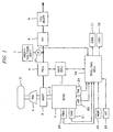
- FIG. 1 is a block diagram showing the configuration of an essential part of a hybrid vehicle according to a preferred embodiment of the present invention.
- Reference numeral 1 denotes an Internal combustion engine (which will be hereinafter referred to as "engine”).
- a drive shaft 2 is driven by the engine 1 so as to drive a drive wheel 5 through a manual transmission 4.
- a motor 3 is provided so as to directly rotate the drive shaft 2.
- the motor 3 also has a regenerative function such that kinetic energy of the rotation of the drive shaft 2 is converted into electrical energy, which is then output.
- the motor 3 is connected to a power drive unit (which will be hereinafter referred to as "PDU") 6.
- the PDU 6 is connected through a current sensor 27 to a high-voltage battery 7 as the electrical energy storing means.
- the high-voltage battery 7 may be replaced by an electrical double layer capacitor having a large electrostatic capacity.
- the PDU 6 is also connected to a voltage reducer 8 for reducing an output voltage from the high-voltage battery 7 to supply a reduced voltage to a 12-V battery 9.
- An output from the 12-V battery 9 is supplied to various electrical devices mounted on the vehicle.
- the PDU 6 is connected to a motor electronic control unit (which will be hereinafter referred to as "MOTECU") 11 for controlling the motor 3.
- the MOTECU 11 is connected to an engine/management electronic control unit (which will be hereinafter referred to as "ENG/MGECU”) 10 for controlling the engine 1 and monitoring an electrical energy quantity in the high-voltage battery 7 to perform energy management.
- the MOTECU 11 controls drive assistance and regeneration by the motor 3 through the PDU 6.
- the current sensor 27 is connected to the ENG/MGECU 10, and a detection signal from the current sensor 27 is supplied to the ENG/MGECU 10.
- the engine 1 is provided with a throttle valve opening sensor 21 for detecting a throttle valve opening THA, an intake pipe absolute pressure sensor 22 for detecting an absolute pressure PBA in an intake pipe of the engine 1 at a position downstream of the throttle valve, an engine rotational speed sensor 23 for detecting a rotational speed NE of the engine 1, and an engine coolant temperature sensor 24 for detecting an engine coolant temperature TW. Detection signals output from these sensors 21, 22, 23, and 24 are supplied to the ENG/MGECU 10. Further, the vehicle is provided with a shift position sensor 25 for detecting a shift position NGR of the transmission 4, and a vehicle speed sensor 26 for detecting a running speed (vehicle speed) VP of the vehicle. Detection signals output from these sensors 25 and 26 are also supplied to the ENG/MGECU 10.
- the ENG/MGECU 10 includes a CPU (Central Processing Unit), ROM (Read Only Memory), RAM (Random Access Memory), and an input/output circuit.
- the ENG/MGECU 10 controls a fuel amount to be supplied to the engine 1 according to the detection signals from the above sensors, and also controls drive assistance and regeneration by the motor 3 through the MOTECU 11. More specifically, the ENG/MGECU 10 controls assistance of a drive force by the motor 3 during acceleration of the vehicle and regeneration by the motor 3 during deceleration or cruising of the vehicle according to the engine rotational speed NE, throttle valve opening THA, engine load (PBA), vehicle speed VP, etc.
- the ENG/MGECU 10 performs on/off control of a shift-down indicator lamp 31 and a shift-up indicator lamp 32 each for recommending changing of a shift position to a driver of the vehicle.
- the shift-down indicator lamp 31 is a lamp for recommending changing of a present shift position to a lower-speed shift position higher in transmission gear ratio than the present shift position (e.g., changing from a fourth position to a third position)
- the shift-up indicator lamp 32 is a lamp for recommending changing of a present shift position to a higher-speed shift position lower in transmission gear ratio than the present shift position (e.g., changing from a third position to a fourth position).
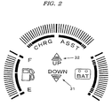
- These lamps 31 and 32 are provided on an indicator panel arranged in front of the driver as shown in FIG. 2.
- the indicator panel shown in FIG. 2 is further provided with a fuel indicator for indicating a remaining fuel amount, a battery indicator for indicating a remaining charge of the battery, and a regeneration/drive assistance indicator in addition to the shift-down indicator lamp 31 and the shift-up indicator lamp 32.
- a fuel indicator for indicating a remaining fuel amount
- a battery indicator for indicating a remaining charge of the battery
- a regeneration/drive assistance indicator in addition to the shift-down indicator lamp 31 and the shift-up indicator lamp 32.
- Each of these indicators is provided with LED's (light emitting diode), which are arranged on the periphery of the indication panel, adapted to be turned on to effect indication.
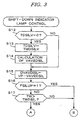
- FIGS. 3 and 4 are flowcharts showing shift-down indicator lamp control processing for the on/off control of the shift-down indicator lamp 31. This processing is executed at predetermined time intervals by the ENG/MGECU 10.
- TMDSILV e.g. 1 second
- VAVEDSIL A x VP + (1 - A) x VAVEDSIL
- A is an averaging coefficient set to a value between 0 and 1 (e.g., 0.25)
- VP is a present value of the detected vehicle speed
- VAVEDSIL on the right side is a previous calculated value of the average vehicle speed.
- TWDSIL e.g. 60°C
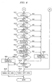
- step S21 it is determined whether or not the vehicle speed VP is higher than a predetermined speed VDSILL (e.g., 10 km/h). If VP > VDSILL, it is determined whether or not the engine rotational speed NE is lower than a predetermined high speed NEDSILH (e.g., 3500 rpm) (step S22). If NE ⁇ NEDSILH, it is determined whether or not the engine rotational speed NE is higher than a predetermined low speed NEDSILL (e.g., 500 rpm) (step S23). If NE > NEDSILL, it is determined whether or not the intake absolute pressure PBA is higher than a predetermined pressure PBDSIL (e.g., 710 mmHg) (step S24).
- a predetermined speed VDSILL e.g. 10 km/h.
- step S25 it is determined whether or not the throttle valve opening THA is larger than a predetermined valve opening THDSIL (e.g., 40 deg) (step S25). If THA > THDSIL, it is determined whether or not the deviation DVAVDSIL calculated in step S15 is smaller than a predetermined deviation DVDSIL (e.g., 2 km/h) (step S26). If DVAVSIL ⁇ DVDSIL, it is determined whether or not the shift position NGR is greater than or equal to a predetermined shift position NGRDSIL (e.g., third position) (step S27). If NGR ⁇ NGRDSIL, it is determined whether or not the previous shift position NGR is less than or equal to the present shift position NGR (step S28).
- THDSIL e.g. 40 deg
- a predetermined time period TMDSILDN (e.g., 3 seconds) is set in a down-count timer TDSILDN to be referred in step S29, and it is then started (step S30). Then, it is determined whether or not a timer value of a down-count timer TDSILDL for delay control which is started in step S31 is "0" (step S32). As far as the shift-down indicator lamp 31 is not turned on, the timer value of the timer TDSILDL is "0", so that the program proceeds to step S34, in which the off state of the shift-down indicator lamp (DSIL) 31 is kept, and this processing is ended.
- TMDSILDN e.g. 3 seconds
- step S21 to S28 are affirmative (YES), that is, if the vehicle speed VP is higher than the predetermined speed VDSILL, the engine rotational speed NE falls between the predetermined high speed NEDSILH and the predetermined low speed NEDSILL, the intake absolute pressure PBA is higher than the predetermined pressure PBDSIL, the throttle valve opening THA is higher than the predetermined valve opening THDSIL (i.e., the engine is in a high-load condition), the deviation DVAVDSIL between the vehicle speed VP and the average vehicle speed VAVEDSIL is smaller than the predetermined deviation DVDSIL (i.e., the vehicle is hardly accelerated), the shift position NGR is greater than the predetermined shift position NGRDSIL (i.e., the transmission is in a low-gear ratio condition), and the shift position NGR is not changed to a shift position higher in transmission gear ratio than the previous shift position (i.e., the transmission is not shifted down), it is determined that the DSIL turning-on conditions have been
- TMDSILDL e.g., 0.5 second
- step S31 If at least one of the DSIL turning-on conditions is changed after execution of step S31, the program proceeds to steps S32 and S33 to keep the on state of the shift-down indicator lamp 31 only during the predetermined delay time TMDSILDL. After the predetermined delay time TMDSILDL has elapsed, the shift-down indicator lamp 31 is turned off.
- One of the above-mentioned DSIL turning-on conditions is that the vehicle is in a high-load running condition such as a hill-climbing condition where the vehicle is hardly accelerated in spite of depression of an accelerator pedal by the driver. That is, in the case that the vehicle is in such a high-load running condition and that the other conditions (steps S16 and S17 shown in FIG. 3 and steps S21 to S23, S27, and S28 shown in FIG. 4) are satisfied, the shift-down indicator lamp 31 is turned on to recommend shift-down to the driver. Then, the shift-down is performed by the driver, so that the engine rotational speed NE becomes relatively high and the proportion of assistance of the drive force by the motor 3 is reduced, thereby preventing continuous consumption of large electric power. As a result, there is no possibility that the electrical energy quantity in the high-voltage battery 7 may become extremely small, and a sufficient drive assist power by the motor 3 can be obtained as required.
- a high-load running condition such as a hill-climbing condition where the
- the throttle valve opening sensor 21, the intake pipe absolute pressure sensor 22, the engine rotational speed sensor 23, the engine coolant temperature sensor 24, the shift position sensor 25, the vehicle speed sensor 26, the steps S12 to S17 in FIG. 3, and the steps S21 to S28 in FIG. 4 correspond to the vehicle operating condition detecting means
- the steps S29 to S34 in FIG. 4 and the shift-down indicator lamp 31 correspond to the shift-down recommending means.
- the steps S24 to S26 in FIG. 4 correspond to the high-load running detecting means.
- the throttle valve opening THA corresponds to "the parameter indicative of the driver's intention of acceleration".
- the present invention is not limited to the above preferred embodiment, but various modifications may be made without departing from the scope of the present invention.
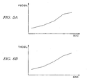
- the predetermined pressure PBDSIL (step S24 in FIG. 4) and the predetermined valve opening THDSIL (step S25 in FIG. 4) both used to determine the high-load operating condition of the engine 1 are constant values in the above preferred embodiment, they may be set according to remaining charge SOC of the high-voltage battery 7 as shown in FIGS. 5A and 5B.
- the remaining charge SOC of the battery 7 is expressed by the proportion (%) of an electrical energy quantity stored in the battery 7 to the total capacity, and it is calculated by adding up the output from the current sensor 27 (adding up the current input into the battery 7 by regeneration as a positive value and the current output from the battery 7 for drive assistance as a negative value).
- shift-down indicator lamp 31 is used as the shift-down recommending means in the above preferred embodiment, it is merely illustrative and any other methods may be adopted.
- a present shift position and a recommended shift position may be indicated by numerals, or the recommendation of shift-down may be made by voice.
- the amount of depression of an accelerator pedal may be used in place of the throttle valve opening THA as the parameter indicative of the driver's intention of acceleration.
- the shift position NGR may be detected according to the vehicle speed VP and the engine rotational speed NE rather than by using the shift position sensor.
Abstract
Description
Claims (3)
- A shift position indicating device for indicating a recommended shift position to a driver of a hybrid vehicle having an engine (1) for driving a drive shaft (2) of said vehicle, a motor (3) for assisting a drive force applied to said drive shaft (2) by electrical energy, said motor (3) having a regenerative function of converting kinetic energy of said drive shaft (2) into electrical energy, and electrical energy storing means (7) for supplying power to said motor (3) and storing electrical energy output from said motor (3), comprisingcharacterized in that said high-load running detecting means includes a vehicle speed detecting means for detecting a vehicle speed of said vehicle, and determines that said vehicle is in said high-load running condition when said engine (1) is in said high-load operating condition and a change in said vehicle speed is small.vehicle operating condition detecting means for detecting an operating condition of said vehicle; said vehicle operating condition detecting means having high-load running detecting means for detecting a high-load running condition of said vehicle; said high-load running detecting means including high-load operating condition detecting means for detecting a high-load operating condition of said engine (1) andshift-down recommending means for recommending shift-down to said driver according to said operating condition detected by said vehicle operating condition detecting means, said shift-down recommending means recommending the shift-down under the condition that said vehicle is in said high-load running conditions,
- A shift position indicating device according to claim 1, wherein said high-load operating condition detecting means determines that said engine (1) is in said high-load operating condition when an intake pressure of said engine (1) is higher than a determination threshold which is set higher with an increase in remaining charge of said electrical energy storing means (7).
- A shift position indicating device according to claim 2, wherein said high-load operating condition detecting means determines that said engine (1) is in said high-load operating condition when a parameter indicative of the driver's intention of acceleration of said vehicle is greater than a determination threshold which is set higher with an increase in remaining charge of said electrical energy storing means (7).
Applications Claiming Priority (2)
| Application Number | Priority Date | Filing Date | Title |
|---|---|---|---|
| JP20105999 | 1999-07-15 | ||
| JP20105999A JP3929646B2 (en) | 1999-07-15 | 1999-07-15 | Hybrid vehicle shift position presentation device |
Publications (3)
| Publication Number | Publication Date |
|---|---|
| EP1068976A2 EP1068976A2 (en) | 2001-01-17 |
| EP1068976A3 EP1068976A3 (en) | 2002-12-04 |
| EP1068976B1 true EP1068976B1 (en) | 2005-12-21 |
Family
ID=16434711
Family Applications (1)
| Application Number | Title | Priority Date | Filing Date |
|---|---|---|---|
| EP00114253A Expired - Lifetime EP1068976B1 (en) | 1999-07-15 | 2000-07-03 | Shift recommendation device for hybrid vehicle |
Country Status (4)
| Country | Link |
|---|---|
| US (1) | US6404332B1 (en) |
| EP (1) | EP1068976B1 (en) |
| JP (1) | JP3929646B2 (en) |
| DE (1) | DE60024927T2 (en) |
Cited By (8)
| Publication number | Priority date | Publication date | Assignee | Title |
|---|---|---|---|---|
| US7921945B2 (en) | 2006-02-21 | 2011-04-12 | Clean Emissions Technologies, Inc. | Vehicular switching, including switching traction modes and shifting gears while in electric traction mode |
| US7921950B2 (en) | 2006-11-10 | 2011-04-12 | Clean Emissions Technologies, Inc. | Electric traction retrofit |
| US8286440B2 (en) | 2005-03-14 | 2012-10-16 | Clean Emissions Technologies, Inc. | Operating a comfort subsystem for a vehicle |
| US8565969B2 (en) | 2007-04-03 | 2013-10-22 | Clean Emissions Technologies, Inc. | Over the road/traction/cabin comfort retrofit |
| US8668035B2 (en) | 2006-03-14 | 2014-03-11 | Clean Emissions Technologies, Inc. | Electric traction system and method |
| US9120483B2 (en) | 2011-11-24 | 2015-09-01 | Toyota Jidosha Kabushiki Kaisha | Gear-shift instruction device for hybrid vehicle |
| US9631528B2 (en) | 2009-09-03 | 2017-04-25 | Clean Emissions Technologies, Inc. | Vehicle reduced emission deployment |
| US9758146B2 (en) | 2008-04-01 | 2017-09-12 | Clean Emissions Technologies, Inc. | Dual mode clutch pedal for vehicle |
Families Citing this family (53)
| Publication number | Priority date | Publication date | Assignee | Title |
|---|---|---|---|---|
| JP3698302B2 (en) * | 2000-04-04 | 2005-09-21 | スズキ株式会社 | Control device for hybrid vehicle |
| DE10210545A1 (en) * | 2002-03-09 | 2003-09-18 | Bosch Gmbh Robert | Speed regulator for manual transmission motor vehicle has radar connected to acceleration control to control gear change function and inform driver that vehicle speed is unsuitable |
| US7160223B2 (en) * | 2003-09-10 | 2007-01-09 | Ford Global Technologies, Llc | Method for inhibiting engine stalling in a hybrid vehicle |
| US7474309B2 (en) * | 2003-12-16 | 2009-01-06 | General Motors Corporation | Hybrid vehicle display apparatus and method |
| US7091839B2 (en) * | 2004-03-09 | 2006-08-15 | Ford Global Technologies, Llc | Indicator for a hybrid electric vehicle |
| US7750796B2 (en) * | 2006-06-27 | 2010-07-06 | Gm Global Technology Operations, Inc. | Regenerative braking halo and method |
| US7646289B2 (en) | 2006-06-27 | 2010-01-12 | Gm Global Technology Operations, Inc. | Fuel economy indicator lamp control system |
| JP4251210B2 (en) * | 2006-11-07 | 2009-04-08 | トヨタ自動車株式会社 | Display device for hybrid vehicle |
| DE102007030524B4 (en) * | 2007-06-16 | 2019-04-11 | Bayerische Motoren Werke Aktiengesellschaft | Display device for a vehicle |
| JP4306776B2 (en) | 2007-09-06 | 2009-08-05 | トヨタ自動車株式会社 | Hybrid vehicle |
| JP4513846B2 (en) * | 2007-09-26 | 2010-07-28 | トヨタ自動車株式会社 | Automobile shift instruction device |
| FR2923290B1 (en) * | 2007-11-05 | 2010-07-30 | Peugeot Citroen Automobiles Sa | AUTOMOTIVE VEHICLE DISPLAY |
| FR2923291B1 (en) * | 2007-11-05 | 2009-12-25 | Peugeot Citroen Automobiles Sa | AUTOMOTIVE VEHICLE DISPLAY |
| FR2936480B1 (en) * | 2008-09-26 | 2011-06-17 | Peugeot Citroen Automobiles Sa | HUMAN / MACHINE INTERFACE FOR DISPLAYING REPRESENTATION OF ORGANS INVOLVED IN THE DISPLACEMENT OF A HYBRID MOTOR VEHICLE AND INFORMATION RELATING TO THE INTERACTIONS BETWEEN THESE BODIES |
| US8207841B2 (en) | 2008-10-28 | 2012-06-26 | Ford Global Technologies, Llc | Vehicle information display and method |
| DE102008055901A1 (en) * | 2008-11-05 | 2009-06-10 | Daimler Ag | Lubricant supply display device for use in vehicle, has auxiliary display elements attached to analog display element such that auxiliary and analog display elements are switched-on for display of fill level of lubricant |
| US20100280688A1 (en) * | 2009-04-30 | 2010-11-04 | Searete Llc, A Limited Liability Corporation Of The State Of Delaware | Awarding standings to a vehicle based upon one or more fuel utilization characteristics |
| US20110106354A1 (en) * | 2009-04-30 | 2011-05-05 | Searete Llc, A Limited Liability Corporation Of The State Of Delaware | Awarding standings to a vehicle based upon one or more fuel utilization characteristics |
| US20100280706A1 (en) * | 2009-04-30 | 2010-11-04 | Searete Llc, A Limited Liability Corporation Of State Of Delaware | Awarding standings to a vehicle based upon one or more fuel utilization characteristics |
| US20100280708A1 (en) * | 2009-04-30 | 2010-11-04 | Searete Llc, A Limited Liability Corporation Of The State Of Delaware | Awarding standings to a vehicle based upon one or more fuel utilization characteristics |
| US20100280887A1 (en) * | 2009-04-30 | 2010-11-04 | Searete Llc, A Limited Liability Corporation Of The State Of Delaware | Awarding privileges to a vehicle based upon one or more fuel utilization characteristics |
| US20100280888A1 (en) * | 2009-04-30 | 2010-11-04 | Searete LLC, a limited libaility corporation of the State of Delaware | Awarding privileges to a vehicle based upon one or more fuel utilization characteristics |
| US20100280692A1 (en) * | 2009-04-30 | 2010-11-04 | Searete Llc, A Limited Liability Corporation Of The State Of Delaware | Awarding standings to a vehicle based upon one or more fuel utilization characteristics |
| US20100280707A1 (en) * | 2009-04-30 | 2010-11-04 | Searete Llc, A Limited Liability Corporation Of State Of Delaware | Awarding standings to a vehicle based upon one or more fuel utilization characteristics |
| US20100280886A1 (en) * | 2009-04-30 | 2010-11-04 | Searete Llc, A Limited Liability Corporation Of The State Of Delware | Awarding privileges to a vehicle based upon one or more fuel utilization characteristics |
| US20100280689A1 (en) * | 2009-04-30 | 2010-11-04 | Searete Llc, A Limited Liability Corporation Of The State Of Delaware | Awarding standings to a vehicle based upon one or more fuel utilization characteristics |
| US20100280704A1 (en) * | 2009-04-30 | 2010-11-04 | Searete Llc, A Limited Liability Corporation Of The State Of Delaware | Awarding standings to a vehicle based upon one or more fuel utilization characteristics |
| US20100280686A1 (en) * | 2009-04-30 | 2010-11-04 | Searete Llc, A Limited Liability Corporation Of The State Of Delaware | Awarding privileges to a vehicle based upon one or more fuel utilization characteristics |
| US8855907B2 (en) * | 2009-04-30 | 2014-10-07 | Searete Llc | Awarding privileges to a vehicle based upon one or more fuel utilization characteristics |
| US20110106591A1 (en) * | 2009-04-30 | 2011-05-05 | Searete Llc, A Limited Liability Corporation Of The State Of Delaware | Awarding standings to a vehicle based upon one or more fuel utilization characteristics |
| US20100280691A1 (en) * | 2009-04-30 | 2010-11-04 | Searete Llc, A Limited Liability Corporation Of The State Of Delaware | Awarding standings to a vehicle based upon one or more fuel utilization characteristics |
| US20100280709A1 (en) * | 2009-04-30 | 2010-11-04 | Searete Llc, A Limited Liability Corporation Of The State Of Delaware | Awarding standings to a vehicle based upon one or more fuel utilization characteristics |
| US20100280690A1 (en) * | 2009-04-30 | 2010-11-04 | Searete Llc, A Limited Liability Corporation Of The State Of Delaware | Awarding standings to a vehicle based upon one or more fuel utilization characteristics |
| US20100280885A1 (en) * | 2009-04-30 | 2010-11-04 | Searete Llc, A Limited Liability Corporation Of The State Of Delaware | Awarding privileges to a vehicle based upon one or more fuel utilization characteristics |
| US20100280705A1 (en) * | 2009-04-30 | 2010-11-04 | Searete Llc, A Limited Liability Corporation Of The State Of Delaware | Awarding standings to a vehicle based upon one or more fuel utilization characteristics |
| DE102010021343A1 (en) * | 2009-09-04 | 2011-03-10 | Volkswagen Ag | Method and device for providing information in a vehicle |
| JP2011127640A (en) | 2009-12-15 | 2011-06-30 | Toyota Motor Corp | Control device of vehicle |
| DE202010003772U1 (en) * | 2010-03-17 | 2011-04-28 | Miorin, Martin | information means |
| US9145048B2 (en) * | 2010-03-31 | 2015-09-29 | General Electric Company | Apparatus for hybrid engine control and method of manufacture same |
| US8543308B2 (en) | 2010-04-19 | 2013-09-24 | GM Global Technology Operations LLC | Systems and methods for communicating optimal driving information |
| WO2012004842A1 (en) * | 2010-07-05 | 2012-01-12 | パイオニア株式会社 | Driving maneuver assistance device and driving maneuver assistance method |
| FR2975639B1 (en) * | 2011-05-25 | 2013-06-28 | Peugeot Citroen Automobiles Sa | MANUAL TRANSMISSION VEHICLE HAVING A HYBRID TRACTION CHAIN AND METHOD OF HYBRIDIZING THE SAME |
| WO2013069120A1 (en) * | 2011-11-09 | 2013-05-16 | トヨタ自動車株式会社 | Gear shift indicator |
| EP2792563B1 (en) * | 2011-12-15 | 2020-11-18 | Toyota Jidosha Kabushiki Kaisha | Hybrid vehicle control apparatus |
| CN103402844A (en) * | 2012-02-27 | 2013-11-20 | 丰田自动车株式会社 | Hybrid vehicle |
| FR2989141B1 (en) * | 2012-04-06 | 2015-07-03 | Peugeot Citroen Automobiles Sa | METHOD FOR AIDING THE MANAGEMENT OF A TRANSMISSION MEMBER OF A HYBRID MOTOR VEHICLE WITH A MANUAL GEARBOX AND A HYBRID AUTOMOTIVE VEHICLE |
| KR101977864B1 (en) * | 2012-07-17 | 2019-05-14 | 콘티넨탈 오토모티브 시스템 주식회사 | INDICATING METHOD FOR GEAR UP-shift |
| JP5994794B2 (en) * | 2013-01-08 | 2016-09-21 | トヨタ自動車株式会社 | Control device for hybrid vehicle |
| DE102014205329A1 (en) * | 2014-03-21 | 2015-09-24 | Robert Bosch Gmbh | Hybrid powertrain |
| CN105805291B (en) * | 2016-04-18 | 2018-05-11 | 北汽福田汽车股份有限公司 | Shift control mechanism and speed changer and vehicle with the shift control mechanism |
| DE102017127369B3 (en) * | 2017-11-21 | 2019-05-16 | Schaeffler Technologies AG & Co. KG | Method for controlling a hybrid powertrain of a motor vehicle |
| JP2022036843A (en) * | 2020-08-24 | 2022-03-08 | トヨタ自動車株式会社 | Electric automobile |
| JP7452576B2 (en) | 2022-05-27 | 2024-03-19 | トヨタ自動車株式会社 | Shift device for pseudo-manual transmission EV vehicle |
Family Cites Families (11)
| Publication number | Priority date | Publication date | Assignee | Title |
|---|---|---|---|---|
| US4042056A (en) * | 1975-11-21 | 1977-08-16 | Automobile Corporation Of America | Hybrid powered automobile |
| IT1071809B (en) * | 1976-11-02 | 1985-04-10 | Fiat Spa | SIGNALING SYSTEM FOR A MOTOR VEHICLE DRIVEN BY AN INTERNAL COMBUSTION ENGINE AND PROVIDED WITH A MULTIPLE SPEED CHANGE TO PROVIDE THE DRIVER WITH A SIGNALING RELATIVE TO THE GEAR RATIO TO BE ADOPTED TO REALIZE THE LOWER CONSUMPTION |
| DE3101056A1 (en) * | 1981-01-15 | 1982-08-05 | Daimler-Benz Ag, 7000 Stuttgart | METHOD AND DEVICE FOR DETERMINING SWITCHING SIGNALS |
| JPS5963230A (en) * | 1982-10-04 | 1984-04-10 | Toyota Motor Corp | Apparatus for displaying optimum shift timing of vehicle |
| SE450504B (en) | 1983-07-26 | 1987-06-29 | Bofors Wear Parts Ab | WRADING SYSTEM FOR EQUIPMENT TOOLS |
| JPS6182057A (en) * | 1984-09-28 | 1986-04-25 | Honda Motor Co Ltd | Shift-up instruction method of manual speed changer |
| JPS6181824A (en) * | 1984-09-28 | 1986-04-25 | Honda Motor Co Ltd | Shift-down indicating method for manual speed changer |
| JP3412352B2 (en) * | 1995-08-15 | 2003-06-03 | アイシン・エィ・ダブリュ株式会社 | Control device for vehicle drive unit |
| JP3749302B2 (en) * | 1996-04-11 | 2006-02-22 | トヨタ自動車株式会社 | Drive control apparatus for hybrid vehicle |
| DE19714495A1 (en) * | 1997-04-08 | 1998-10-15 | Bayerische Motoren Werke Ag | Dialing device with a display device |
| GB9720172D0 (en) * | 1997-09-24 | 1997-11-26 | Rover Group | A transmission control system for a vehicle |
-
1999
- 1999-07-15 JP JP20105999A patent/JP3929646B2/en not_active Expired - Fee Related
-
2000
- 2000-07-03 EP EP00114253A patent/EP1068976B1/en not_active Expired - Lifetime
- 2000-07-03 DE DE60024927T patent/DE60024927T2/en not_active Expired - Lifetime
- 2000-07-13 US US09/615,730 patent/US6404332B1/en not_active Expired - Lifetime
Cited By (11)
| Publication number | Priority date | Publication date | Assignee | Title |
|---|---|---|---|---|
| US8286440B2 (en) | 2005-03-14 | 2012-10-16 | Clean Emissions Technologies, Inc. | Operating a comfort subsystem for a vehicle |
| US7921945B2 (en) | 2006-02-21 | 2011-04-12 | Clean Emissions Technologies, Inc. | Vehicular switching, including switching traction modes and shifting gears while in electric traction mode |
| US8668035B2 (en) | 2006-03-14 | 2014-03-11 | Clean Emissions Technologies, Inc. | Electric traction system and method |
| US9457792B2 (en) | 2006-03-14 | 2016-10-04 | Clean Emissions Technologies, Inc. | Retrofitting a vehicle drive train |
| US7921950B2 (en) | 2006-11-10 | 2011-04-12 | Clean Emissions Technologies, Inc. | Electric traction retrofit |
| US8565969B2 (en) | 2007-04-03 | 2013-10-22 | Clean Emissions Technologies, Inc. | Over the road/traction/cabin comfort retrofit |
| US9707861B2 (en) | 2008-03-19 | 2017-07-18 | Clean Emissions Technologies, Inc. | Data acquisition for operation of a vehicle |
| CN102015405B (en) * | 2008-04-01 | 2013-08-28 | 无污染发射技术股份有限公司 | Vehicular switching while in electric traction mode |
| US9758146B2 (en) | 2008-04-01 | 2017-09-12 | Clean Emissions Technologies, Inc. | Dual mode clutch pedal for vehicle |
| US9631528B2 (en) | 2009-09-03 | 2017-04-25 | Clean Emissions Technologies, Inc. | Vehicle reduced emission deployment |
| US9120483B2 (en) | 2011-11-24 | 2015-09-01 | Toyota Jidosha Kabushiki Kaisha | Gear-shift instruction device for hybrid vehicle |
Also Published As
| Publication number | Publication date |
|---|---|
| DE60024927T2 (en) | 2006-06-22 |
| JP2001027321A (en) | 2001-01-30 |
| JP3929646B2 (en) | 2007-06-13 |
| EP1068976A3 (en) | 2002-12-04 |
| EP1068976A2 (en) | 2001-01-17 |
| US6404332B1 (en) | 2002-06-11 |
| DE60024927D1 (en) | 2006-01-26 |
Similar Documents
| Publication | Publication Date | Title |
|---|---|---|
| EP1068976B1 (en) | Shift recommendation device for hybrid vehicle | |
| EP0808735B1 (en) | Control system for hybrid vehicles | |
| US8271156B2 (en) | Hybrid vehicle and control method thereof | |
| EP0812717B1 (en) | Control system for hybrid vehicles | |
| US6234932B1 (en) | Control apparatus for a hybrid vehicle | |
| US9475486B2 (en) | Controller for hybrid vehicle | |
| JP3536838B2 (en) | Vehicle driving force control device | |
| US5862497A (en) | Control system for hybrid vehicles | |
| US6177773B1 (en) | Regeneration control device for a hybrid vehicle | |
| US5984033A (en) | Control system for hybrid vehicles | |
| US6253127B1 (en) | Engine startup control device and control method | |
| US20100038159A1 (en) | Vehicle and control method thereof | |
| US6362536B1 (en) | Apparatus and method for controlling power generation for hybrid vehicle | |
| JP2007223404A (en) | Controller of hybrid vehicle | |
| US10882390B2 (en) | Vehicle | |
| EP0800948B1 (en) | Control system for hybrid vehicles | |
| JP2020100360A (en) | Torque control device of four wheel drive vehicle | |
| JPH06245321A (en) | Controller for engine driven generator in electric automobile | |
| JP2006275175A (en) | Control device of hybrid car | |
| JP3622291B2 (en) | Vehicle travelable distance display device | |
| JP3518192B2 (en) | Vehicle control device | |
| JP4242045B2 (en) | Driving force control device for front and rear wheel drive vehicle | |
| JP3683340B2 (en) | Control device for automatic transmission | |
| JP2021046141A (en) | Power generation control device | |
| JP2006161841A (en) | Controller for hybrid vehicle |
Legal Events
| Date | Code | Title | Description |
|---|---|---|---|
| PUAI | Public reference made under article 153(3) epc to a published international application that has entered the european phase |
Free format text: ORIGINAL CODE: 0009012 |
|
| AK | Designated contracting states |
Kind code of ref document: A2 Designated state(s): AT BE CH CY DE DK ES FI FR GB GR IE IT LI LU MC NL PT SE |
|
| AX | Request for extension of the european patent |
Free format text: AL;LT;LV;MK;RO;SI |
|
| PUAL | Search report despatched |
Free format text: ORIGINAL CODE: 0009013 |
|
| AK | Designated contracting states |
Kind code of ref document: A3 Designated state(s): AT BE CH CY DE DK ES FI FR GB GR IE IT LI LU MC NL PT SE |
|
| AX | Request for extension of the european patent |
Free format text: AL;LT;LV;MK;RO;SI |
|
| RIC1 | Information provided on ipc code assigned before grant |
Free format text: 7B 60K 41/00 A, 7F 16H 61/02 B, 7B 60K 6/02 B, 7F 16H 59/02 B, 7B 60L 11/12 B, 7F 16H 63/42 B |
|
| 17P | Request for examination filed |
Effective date: 20030404 |
|
| AKX | Designation fees paid |
Designated state(s): DE GB |
|
| 17Q | First examination report despatched |
Effective date: 20040609 |
|
| GRAP | Despatch of communication of intention to grant a patent |
Free format text: ORIGINAL CODE: EPIDOSNIGR1 |
|
| RTI1 | Title (correction) |
Free format text: SHIFT RECOMMENDATION DEVICE FOR HYBRID VEHICLE |
|
| GRAS | Grant fee paid |
Free format text: ORIGINAL CODE: EPIDOSNIGR3 |
|
| GRAA | (expected) grant |
Free format text: ORIGINAL CODE: 0009210 |
|
| AK | Designated contracting states |
Kind code of ref document: B1 Designated state(s): DE GB |
|
| REG | Reference to a national code |
Ref country code: GB Ref legal event code: FG4D |
|
| REF | Corresponds to: |
Ref document number: 60024927 Country of ref document: DE Date of ref document: 20060126 Kind code of ref document: P |
|
| PLBE | No opposition filed within time limit |
Free format text: ORIGINAL CODE: 0009261 |
|
| STAA | Information on the status of an ep patent application or granted ep patent |
Free format text: STATUS: NO OPPOSITION FILED WITHIN TIME LIMIT |
|
| 26N | No opposition filed |
Effective date: 20060922 |
|
| PGFP | Annual fee paid to national office [announced via postgrant information from national office to epo] |
Ref country code: DE Payment date: 20150630 Year of fee payment: 16 Ref country code: GB Payment date: 20150701 Year of fee payment: 16 |
|
| REG | Reference to a national code |
Ref country code: DE Ref legal event code: R119 Ref document number: 60024927 Country of ref document: DE |
|
| GBPC | Gb: european patent ceased through non-payment of renewal fee |
Effective date: 20160703 |
|
| PG25 | Lapsed in a contracting state [announced via postgrant information from national office to epo] |
Ref country code: DE Free format text: LAPSE BECAUSE OF NON-PAYMENT OF DUE FEES Effective date: 20170201 |
|
| PG25 | Lapsed in a contracting state [announced via postgrant information from national office to epo] |
Ref country code: GB Free format text: LAPSE BECAUSE OF NON-PAYMENT OF DUE FEES Effective date: 20160703 |