EP0947814B1 - Procedure for obtaining an airtight connection between two diaphragms - Google Patents
Procedure for obtaining an airtight connection between two diaphragms Download PDFInfo
- Publication number
- EP0947814B1 EP0947814B1 EP99104584A EP99104584A EP0947814B1 EP 0947814 B1 EP0947814 B1 EP 0947814B1 EP 99104584 A EP99104584 A EP 99104584A EP 99104584 A EP99104584 A EP 99104584A EP 0947814 B1 EP0947814 B1 EP 0947814B1
- Authority
- EP
- European Patent Office
- Prior art keywords
- diaphragms
- diaphragm
- membranes
- membrane
- brought together
- Prior art date
- Legal status (The legal status is an assumption and is not a legal conclusion. Google has not performed a legal analysis and makes no representation as to the accuracy of the status listed.)
- Expired - Lifetime
Links
Images
Classifications
-
- G—PHYSICS
- G01—MEASURING; TESTING
- G01L—MEASURING FORCE, STRESS, TORQUE, WORK, MECHANICAL POWER, MECHANICAL EFFICIENCY, OR FLUID PRESSURE
- G01L9/00—Measuring steady of quasi-steady pressure of fluid or fluent solid material by electric or magnetic pressure-sensitive elements; Transmitting or indicating the displacement of mechanical pressure-sensitive elements, used to measure the steady or quasi-steady pressure of a fluid or fluent solid material, by electric or magnetic means
- G01L9/0041—Transmitting or indicating the displacement of flexible diaphragms
- G01L9/0042—Constructional details associated with semiconductive diaphragm sensors, e.g. etching, or constructional details of non-semiconductive diaphragms
- G01L9/0044—Constructional details of non-semiconductive diaphragms
-
- Y—GENERAL TAGGING OF NEW TECHNOLOGICAL DEVELOPMENTS; GENERAL TAGGING OF CROSS-SECTIONAL TECHNOLOGIES SPANNING OVER SEVERAL SECTIONS OF THE IPC; TECHNICAL SUBJECTS COVERED BY FORMER USPC CROSS-REFERENCE ART COLLECTIONS [XRACs] AND DIGESTS
- Y10—TECHNICAL SUBJECTS COVERED BY FORMER USPC
- Y10S—TECHNICAL SUBJECTS COVERED BY FORMER USPC CROSS-REFERENCE ART COLLECTIONS [XRACs] AND DIGESTS
- Y10S261/00—Gas and liquid contact apparatus
- Y10S261/37—Modern pumps diaphragm
-
- Y—GENERAL TAGGING OF NEW TECHNOLOGICAL DEVELOPMENTS; GENERAL TAGGING OF CROSS-SECTIONAL TECHNOLOGIES SPANNING OVER SEVERAL SECTIONS OF THE IPC; TECHNICAL SUBJECTS COVERED BY FORMER USPC CROSS-REFERENCE ART COLLECTIONS [XRACs] AND DIGESTS
- Y10—TECHNICAL SUBJECTS COVERED BY FORMER USPC
- Y10T—TECHNICAL SUBJECTS COVERED BY FORMER US CLASSIFICATION
- Y10T29/00—Metal working
- Y10T29/49—Method of mechanical manufacture
- Y10T29/49826—Assembling or joining
- Y10T29/49863—Assembling or joining with prestressing of part
Definitions
- the present invention relates to a method for airtight connection of two Membranes.
- DE 44 19 593 A1 discloses a pressure sensor, which is arranged in a pressure measuring chamber, which is located on a suitable Position in the hose or channel through which a liquid or gas flows located.
- the pressure measuring chamber has an opening in which one by means of a Clamping device extends smoothly tensioned membrane, which depending on the is deflected in the flowing fluid pressure prevailing.
- a pressure transmission part arranged that the movements of the pressurized membrane follows and that also consists of a membrane.
- the airtight connection both membranes are made in such a way that they are pressed in their edge areas, the space remaining between the membranes being kept as small as possible shall be.
- Steps create a bulge in one of the membranes, attach the convex curved side of the membrane onto the membrane to be connected so that it is airtight, merging of the membranes to the edge areas of the membranes with each other communicate and apply an airtight membrane in the edge area final pressing force.
- Such a method makes it possible to completely displace the air between the two membranes and allow air to enter to prevent.
- This is achieved in that the convex curvature of the bulged Membrane pressed into the other membrane when merging will, causing the air between the two membranes to gradually increase is ousted.
- the membranes are brought together until the Finally, membranes also lie on one another in their edge regions.
- the convex curvature of one of the membranes means that, in contrast for the planar stacking of two membranes, the possibility excluded is that after merging and pressing the edge areas an air cushion remains in the area between the membranes.
- a displacement of the air between the membranes in that the connection of both membranes initially not over the entire cross-sectional area, but at the beginning of the merging only in a protrusion formed by the curvature Area of the membrane.
- a first membrane a first chamber of a membrane unit of a metering pump for receiving a Working fluids and a second membrane to accommodate a second chamber promoting fluid, and the bulge of the first membrane generated will increase the pressure on the working fluid in the first chamber.
- the second chamber before merging both membranes are filled with a fluid and partially by merging or is completely emptied.
- the second chamber can be filled with a liquid or be filled, for example, with a pressurized gas that is brought together corresponding to the convex curvature of the first membrane from the second chamber is pressed.
- the attachment and merging both chambers with the help of a guide In particular is the exact placement of the curved membrane on the thus making it easier to connect the airtight membrane at the desired position.
- the merging of both chambers with the help of a guide also ensures that the edge areas of the membranes lie exactly on top of one another, so that is ensured that the airtight connection in the entire edge area of the membranes he follows.
- the chambers are each arranged in a housing part and after merging by means of a clamping device arranged on the housing parts with the desired pressing force are held together. This ensures that always a sufficient pressing force for the airtight connection on the edge areas of the membranes is applied.
- the curvature of one of the membranes can occur during the merging of the two Membranes are enlarged.
- the displacement of the air between the two Membranes or the increase in the contact area of both membranes is not only by merging, but also by increasing the bulge reached one of the membranes.
- a membrane is one Diaphragm pump head with the diaphragm that limits the working fluid Diaphragm pump can be connected after putting on the already bulged Membrane and during the merging of both membranes of the Pressure in the working fluid can be increased such that the convex bulge of the first membrane is enlarged.
- the curvature the membrane is designed such that the membrane to be connected therewith largely or completely deflected after merging the two membranes becomes. This ensures that all the air is particularly reliable is displaced between the two membranes before the edge areas of the membranes be connected to each other.
- the convex curvature of the membrane can already be fully formed during the placement of the membrane or be enlarged during the merge.
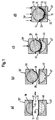
- FIG. 1a shows the housing 30 'of a diaphragm pump in which the chamber 30 is arranged is.
- the chamber 30 is delimited by the membrane 10 and contains according to a suitable working medium of the diaphragm pump in the present exemplary embodiment, such as. Oil.
- Fig. 1a also shows the housing 40 'with the arranged therein Chamber 40, which in turn is delimited by membrane 20.
- the Chamber 40 contains any medium to be conveyed by the diaphragm pump, such as. a dialysis fluid.
- the housing 40 ' represents the diaphragm pump head and has (not shown) connections for the supply and discharge of the promoting medium.
- the housing 40 ' can, for example, be one in each Application of disposable items to be exchanged for a diaphragm pump of a dialyzer, in particular a peritoneal dialysis machine.
- FIG. 1a shows the membranes 10, 20 in their separated by the space 100 Initial state before using the method according to the invention.
- the membranes 10, 20 are in their edge regions 12, 22 with the housing parts 30 ', 40' connected.
- FIG. 1b shows the membrane 10 in a convexly curved state, which is thereby is generated that the pressure on the working medium in the chamber 30 is increased. This can happen, for example, that the piston one piston unit connected to the diaphragm pump is moved accordingly becomes.
- Fig. 1c the state of both membranes 10, 20 is after the domed ones Membrane 10 on the membrane that is thus airtight and completely to be connected 20 shown.
- the bulged membrane 10 is first centered on the Membrane 20 placed and then the housing parts 30 ', 40' are brought together.
- the membrane 20 becomes correspondingly concave inwards moves and the air between the two membranes 10, 20 radially after led outside. It is thus achieved that the enlarging when merging Contact surface of both membranes 10, 20 always and reliably in one air-free condition is maintained.
- Membrane 20 Before the curved membrane 10 is put on, the membrane to be connected to it can be connected Membrane 20 may be flat or a slight convex or concave Have curvature, which must, however, be less than the convex curvature of the Membrane 10.
- Fig. 1d shows both membranes 10, 20, which after merging in their Cross-sectional area and also in their edge region 12, 22 in connection with each other stand.
- the method according to the invention enables application dispense with vacuum pumps when connecting the membranes, which is the corresponding Devices or the method to be simplified.
Description
Die vorliegende Erfindung betrifft ein Verfahren zur luftdichten Verbindung zweier Membranen.The present invention relates to a method for airtight connection of two Membranes.
Die Problemstellung, zwei Membranen derart miteinander zu verbinden, daß der zwischen den Membranen verbleibende Raum möglichst klein und gegenüber dem die Membranen umgebenden Medium abgedichtet ist, ist beispielsweise aus dem Bereich der Drucksensoren bekannt. Die DE 44 19 593 A1 offenbart einen Drucksensor, der in einer Druckmeßkammer angeordnet ist, die sich an einer geeigneten Position in dem von einer Flüssigkeit oder Gas durchströmten Schlauch oder Kanal befindet. Die Druckmeßkammer weist eine Öffnung auf, in der sich eine mittels einer Spannvorrichtung glatt gespannte Membran erstreckt, die in Abhängigkeit des in dem strömenden Fluid herrschenden Druckes ausgelenkt wird. In dem von Druckschwankungen des Fluids beeinflußten Bereich der Membran ist ein Druckübertragungsteil angeordnet, das den Bewegungen der druckbeaufschlagten Membran folgt und das ebenfalls aus einer Membran besteht. Die luftdichte Verbindung beider Membranen erfolgt derart, daß diese in ihren Randbereichen verpreßt werden, wobei der zwischen den Membranen verbleibende Raum möglichst klein gehalten werden soll.The problem of connecting two membranes so that the space remaining between the membranes is as small as possible and compared to that the medium surrounding the membranes is sealed, for example from the Known range of pressure sensors. DE 44 19 593 A1 discloses a pressure sensor, which is arranged in a pressure measuring chamber, which is located on a suitable Position in the hose or channel through which a liquid or gas flows located. The pressure measuring chamber has an opening in which one by means of a Clamping device extends smoothly tensioned membrane, which depending on the is deflected in the flowing fluid pressure prevailing. In the of Pressure fluctuations of the fluid-affected area of the membrane is a pressure transmission part arranged that the movements of the pressurized membrane follows and that also consists of a membrane. The airtight connection both membranes are made in such a way that they are pressed in their edge areas, the space remaining between the membranes being kept as small as possible shall be.
Aus der EP 0 130 441 ist eine Vorrichtung bekannt, bei der eine mit Druck beaufschlagte Membran dadurch vollständig mit einer Membran einer Druckmeßvorrichtung verbunden wird, daß die Luft zwischen beiden Membranen mittels einer Vakuumpumpe abgesaugt wird. Eine derartige Vorrichtung ermöglicht aufgrund des dichten Aufeinanderliegens beider Membranen die Messung von Über- und Unterdrucken, weist jedoch den Nachteil auf, daß stets Mittel zur Vakuumerzeugung erforderlich sind, um einen zuverlässigen Betrieb der Vorrichtung zu gewährleisten.From EP 0 130 441 a device is known in which one is pressurized Membrane completely with a membrane of a pressure measuring device is connected that the air between the two membranes by means of a vacuum pump is suctioned off. Such a device enables due to dense superimposition of both membranes, the measurement of overpressure and underpressure, has the disadvantage, however, that means for vacuum generation are always required are to ensure reliable operation of the device.
Es ist die Aufgabe der vorliegenden Erfindung, ein einfaches Verfahren zur luftdichten und vollständigen Verbindung zweier Membranen zur Verfügung zu stellen.It is the object of the present invention to provide a simple airtight method and complete connection of two membranes.
Diese Aufgabe wird erfindungsgemäß dadurch gelöst, daß das Verfahren die Schritte Erzeugung einer Wölbung einer der Membranen, Aufsetzen der konvex gewölbten Seite der Membran auf die damit luftdicht zu verbindende Membran, Zusammenführen der Membranen bis die Randbereiche der Membranen miteinander in Verbindung stehen und Aufbringen einer die Membranen im Randbereich luftdicht abschließenden Preßkraft. Durch ein derartiges Verfahren wird es möglich, die Luft zwischen beiden Membranen vollständig zu verdrängen und einen Luftzutritt zu verhindern. Dies wird dadurch erreicht, daß die konvexe Wölbung der ausgewölbten Membran beim Zusammenführen in die andere Membran eingedrückt wird, wodurch die Luft zwischen beiden Membranen entsprechend nach und nach verdrängt wird. Das Zusammenführen der Membranen wird durchgeführt, bis die Membranen schließlich auch in ihren Randbereichen aufeinanderliegen. Um die Zufuhr von Luft aus dem die Membranen umgebenden Bereich zu vermeiden, wird erfindungsgemäß nach dem Zusammenführen der Membranen eine Preßkraft aufgebracht, die bewirkt, daß die Membranen in ihrem Randbereich luftdicht abgeschlossen werden. Somit wird der Vorteil erreicht, daß zum einen eine luftdichte und zum anderen eine vollständige Verbindung der Membranen erzielt wird, was dazu führt, daß bei Unter- wie auch bei Überdrücken eine zuverlässige Verbindung und somit eine stets synchrone Bewegung der Membranen gewährleistet wird.This object is achieved in that the method Steps create a bulge in one of the membranes, attach the convex curved side of the membrane onto the membrane to be connected so that it is airtight, merging of the membranes to the edge areas of the membranes with each other communicate and apply an airtight membrane in the edge area final pressing force. Such a method makes it possible to completely displace the air between the two membranes and allow air to enter to prevent. This is achieved in that the convex curvature of the bulged Membrane pressed into the other membrane when merging will, causing the air between the two membranes to gradually increase is ousted. The membranes are brought together until the Finally, membranes also lie on one another in their edge regions. To the Avoid supply of air from the area surrounding the membranes according to the invention, after the membranes have been brought together, a pressing force is applied, which causes the membranes to be airtight in their edge area become. This has the advantage that, on the one hand, an airtight seal and on the other hand a complete connection of the membranes is achieved, which leads to a reliable connection in both negative and positive pressures and thus a synchronous movement of the membranes is guaranteed.
Durch die konvexe Wölbung einer der Membranen wird erreicht, daß, im Gegensatz zum planen Aufeinanderlegen zweier Membranen, die Möglichkeit ausgeschlossen wird, daß nach dem Zusammenführen und Verpressen der Randbereiche ein Luftpolster im Bereich zwischen den Membranen verbleibt. Erfindungsgemäß erfolgt eine Verdrängung der Luft zwischen den Membranen dadurch, daß die Verbindung beider Membranen zunächst nicht über die gesamte Querschnittsfläche, sondern zu Beginn des Zusammenführens nur in einem durch die Wölbung gebildeten vorstehenden Bereich der Membran erfolgt.The convex curvature of one of the membranes means that, in contrast for the planar stacking of two membranes, the possibility excluded is that after merging and pressing the edge areas an air cushion remains in the area between the membranes. According to the invention a displacement of the air between the membranes in that the connection of both membranes initially not over the entire cross-sectional area, but at the beginning of the merging only in a protrusion formed by the curvature Area of the membrane.
In weiterer Ausgestaltung der Erfindung ist vorgesehen, daß eine erste Membran eine erste Kammer einer Membraneinheit einer Dosierpumpe zur Aufnahme eines Arbeitsfluids und eine zweite Membran eine zweite Kammer zur Aufnahme eines zu fördernden Fluids begrenzt, und die Auswölbung der ersten Membran dadurch erzeugt wird, daß der Druck auf das Arbeitsfluid in der ersten Kammer erhöht wird. Somit wird es möglich, die Membran eines Pumpenkopfes einer Membranpumpe luftdicht und vollständig mit der die das Arbeitsfluid begrenzenden Membran der Pumpe zu verbinden. Dazu wird beispielsweise durch die Bewegung eines Kolbens der Druck des Arbeitsfluids geringfügig erhöht, wodurch sich eine konvexe Wölbung der das Arbeitsfluid begrenzenden Membran ergibt. Das Verbinden der Membran des Pumpenkopfes mit der konvex ausgewölbten ersten Membran erfolgt nach dem erfindungsgemäßen Verfahren, wonach die gewölbte Membran auf die damit zu verbindende Membran des Pumpenkopfes aufgesetzt wird, beide Membranen zusammengeführt werden bis ihre Randbereiche miteinander in Verbindung stehen und anschließend eine die Membranen im Randbereich luftdicht abschließende Preßkraft aufgebracht wird.In a further embodiment of the invention it is provided that a first membrane a first chamber of a membrane unit of a metering pump for receiving a Working fluids and a second membrane to accommodate a second chamber promoting fluid, and the bulge of the first membrane generated will increase the pressure on the working fluid in the first chamber. This makes it possible to use the diaphragm of a pump head of a diaphragm pump airtight and complete with the membrane that limits the working fluid Connect pump. This is done, for example, by moving a piston the pressure of the working fluid increases slightly, causing a convex curvature of the membrane that limits the working fluid. Connecting the membrane of the pump head with the convexly curved first membrane takes place after the The method according to the invention, according to which the arched membrane towards connecting membrane of the pump head is placed, merged both membranes will be connected until their edge areas and then an airtight one that seals the membranes in the edge area Press force is applied.
Besonders vorteilhaft ist es, wenn die zweite Kammer vor dem Zusammenführen beider Membranen mit einem Fluid gefüllt ist und durch das Zusammenführen teilweise oder vollständig entleert wird. Die zweite Kammer kann mit einer Flüssigkeit oder beispielsweise einem unter Druck stehenden Gas gefüllt sein, das beim Zusammenführen entsprechend der konvexen Wölbung der ersten Membran aus der zweiten Kammer gedrückt wird.It is particularly advantageous if the second chamber before merging both membranes are filled with a fluid and partially by merging or is completely emptied. The second chamber can be filled with a liquid or be filled, for example, with a pressurized gas that is brought together corresponding to the convex curvature of the first membrane from the second chamber is pressed.
In weiterer Ausgestaltung der vorliegenden Erfindung ist vorgesehen, daß das Aufsetzen und Zusammenführen beider Kammern mit Hilfe einer Führung erfolgt. Insbesondere wird dadurch wird das exakte Aufsetzen der gewölbten Membran auf die damit luftdicht zu verbindende Membran an der gewünschten Position erleichtert. Das Zusammenführen beider Kammern mit Hilfe einer Führung stellt ferner sicher, daß die Randbereiche der Membranen exakt aufeinanderliegen, so daß sichergestellt wird, daß die luftdichte Verbindung in dem gesamten Randbereich der Membranen erfolgt.In a further embodiment of the present invention it is provided that the attachment and merging both chambers with the help of a guide. In particular is the exact placement of the curved membrane on the thus making it easier to connect the airtight membrane at the desired position. The merging of both chambers with the help of a guide also ensures that the edge areas of the membranes lie exactly on top of one another, so that is ensured that the airtight connection in the entire edge area of the membranes he follows.
In weiterer Ausgestaltung der vorliegenden Erfindung ist es möglich, daß die Kammern jeweils in einem Gehäuseteil angeordnet sind und nach dem Zusammenführen mittels einer an den Gehäuseteilen angeordneten Spannvorrichtung mit der gewünschten Preßkraft zusammengehalten werden. Dadurch wird sichergestellt, daß stets eine für die luftdichte Verbindung ausreichende Preßkraft auf die Randbereiche der Membranen aufgebracht wird.In a further embodiment of the present invention, it is possible that the chambers are each arranged in a housing part and after merging by means of a clamping device arranged on the housing parts with the desired pressing force are held together. This ensures that always a sufficient pressing force for the airtight connection on the edge areas of the membranes is applied.
Die Wölbung einer der Membranen kann während des Zusammenführens beider Membranen vergrößert werden. Somit wird die Verdrängung der Luft zwischen beiden Membranen bzw. die Vergrößerung der Kontaktfläche beider Membranen nicht nur durch das Zusammenführen, sondern auch durch die Vergrößerung der Auswölbung einer der Membranen erreicht. Soll beispielsweise eine Membran eines Membranpumpenkopfes mit der das Arbeitsfluid begrenzenden Membran der Membranpumpe verbunden werden, kann nach dem Aufsetzen der bereits ausgewölbten Membran und während des Zusammenführens beider Membranen der Druck in dem Arbeitsfluid derart erhöht werden, daß die konvexe Auswölbung der ersten Membran vergrößert wird. The curvature of one of the membranes can occur during the merging of the two Membranes are enlarged. Thus, the displacement of the air between the two Membranes or the increase in the contact area of both membranes is not only by merging, but also by increasing the bulge reached one of the membranes. For example, if a membrane is one Diaphragm pump head with the diaphragm that limits the working fluid Diaphragm pump can be connected after putting on the already bulged Membrane and during the merging of both membranes of the Pressure in the working fluid can be increased such that the convex bulge of the first membrane is enlarged.
In weiterer Ausgestaltung der vorliegenden Erfindung ist vorgesehen, daß die Wölbung der Membran derart ausgebildet ist, daß die damit zu verbindende Membran nach dem Zusammenführen beider Membranen weitgehend oder vollständig ausgelenkt wird. Dadurch wird besonders zuverlässig erreicht, daß die gesamte Luft zwischen beiden Membranen verdrängt wird, bevor die Randbereiche der Membranen miteinander verbunden werden. Die konvexe Wölbung der Membran kann bereits während des Aufsetzens der Membran vollständig ausgebildet sein oder auch während des Zusammenführens vergrößert werden.In a further embodiment of the present invention it is provided that the curvature the membrane is designed such that the membrane to be connected therewith largely or completely deflected after merging the two membranes becomes. This ensures that all the air is particularly reliable is displaced between the two membranes before the edge areas of the membranes be connected to each other. The convex curvature of the membrane can already be fully formed during the placement of the membrane or be enlarged during the merge.
Weitere Vorteile und Einzelheiten der vorliegenden Erfindung werden anhand eines in der Zeichnung dargestellten Ausführungsbeispiels näher erläutert. Es zeigt
- Fig. 1:
- Eine schematische Darstellung des erfindungsgemäßen Verfahrens zum luftdichten und vollständigen Zusammenführen zweier Membranen einer Membranpumpe.
- Fig. 1:
- A schematic representation of the inventive method for airtight and complete merging of two membranes of a membrane pump.
Fig. 1a zeigt das Gehäuse 30' einer Membranpumpe, in dem die Kammer 30 angeordnet
ist. Die Kammer 30 wird durch die Membran 10 begrenzt und enthält gemäß
dem vorliegenden Ausführungsbeispiel ein geeignetes Arbeitsmedium der Membranpumpe,
wie z.B. Öl. Fig. 1a zeigt ferner das Gehäuse 40' mit der darin angeordneten
Kammer 40, die ihrerseits durch die Membran 20 begrenzt wird. Die
Kammer 40 enthält ein beliebiges durch die Membranpumpe zu förderndes Medium,
wie z.B. eine Dialysierflüssigkeit. Das Gehäuse 40' stellt den Membranpumpenkopf
dar und weist (nicht dargestellte) Anschlüsse zur Zu- und Abfuhr des zu
fördernden Mediums auf. Das Gehäuse 40' kann beispielsweise als ein bei jeder
Anwendung auszutauschender Einmalartikel einer Membranpumpe eines Dialysiergerätes,
insbesondere eines Peritonealdialysegerätes, ausgeführt sein.1a shows the housing 30 'of a diaphragm pump in which the
Fig. 1a zeigt die Membranen 10, 20 in ihrem durch den Zwischenraum 100 getrennten
Ausgangszustand vor Anwendung des erfindungsgemäßen Verfahrens.
Die Membranen 10, 20 sind in ihren Randbereichen 12, 22 mit den Gehäuseteilen
30', 40' verbunden. 1a shows the
Fig. 1b stellt die Membran 10 in einem konvex gewölbten Zustand dar, der dadurch
erzeugt wird, daß der Druck auf das in der Kammer 30 befindliche Arbeitsmedium
erhöht wird. Dies kann beispielsweise dadurch geschehen, daß der Kolben einer
mit der Membranpumpe in Verbindung stehenden Kolbeneinheit entsprechend bewegt
wird.1b shows the
In Fig. 1c ist der Zustand beider Membranen 10, 20 nach dem Aufsetzen der gewölbten
Membran 10 auf die damit luftdicht und vollständig zu verbindende Membran
20 dargestellt. Die ausgewölbte Membran 10 wird zunächst zentrisch auf die
Membran 20 aufgesetzt und anschließend werden die Gehäuseteile 30', 40' zusammengeführt.
Dadurch wird die Membran 20 entsprechend konkav nach innen
bewegt und die zwischen beiden Membranen 10, 20 befindliche Luft radial nach
außen geführt. Somit wird erreicht, daß sich die beim Zusammenführen vergrößernde
Kontaktfläche beider Membranen 10, 20 stets und zuverlässig in einem
luftfreien Zustand gehalten wird.In Fig. 1c, the state of both
Vor dem Aufsetzvorgang der gewölbten Membran 10 kann die damit zu verbindende
Membran 20 plan ausgeführt sein oder eine geringe konvexe oder konkave
Wölbung aufweisen, die jedoch geringer sein muß, als die konvexe Wölbung der
Membran 10.Before the
Fig. 1d zeigt beide Membranen 10,20, die nach dem Zusammenführen in ihrer
Querschnittsfläche sowie auch in ihrem Randbereich 12, 22 miteinander in Verbindung
stehen. Durch das allmähliche Zusammenführen beider Membranen 10, 20
wird erreicht, daß der Kontaktbereich zwischen den Membranen 10, 20 von Luft
befreit wird. Das Zusammenführen der Randbereiche 12, 22 sowie das Aufbringen
der Preßkraft bewirkt, daß ein Luftzutritt in den Raum zwischen die Membranen 10,
20 sicher vermieden wird.Fig. 1d shows both
Somit wird sichergestellt, daß nach dem Zusammenführen der beiden Gehäuseteile
30', 40' eine luftfreie und vollständige Verbindung beider Membranen 10, 20 erfolgt,
was zur Folge hat, daß die Membran 20 des Gehäuseteils 40' sowohl bei Unter- als
auch bei Überdruck der Membran 10 folgt. Dadurch wird es möglich, exakt das Volumen
des zu fördernden Fluids in die Kammer 40 zu führen bzw. aus dieser zu
verdrängen, das dem bewegten Volumen des in der Kammer 30 befindlichen Arbeitsfluids
entspricht. Der Einfluß oder der Zutritt von Luft zwischen die Membranen
10, 20, der aufgrund der Kompressibilität zum einen die Dosiergenauigkeit der Vorrichtung
verringern würde und zum anderen durch den fehlenden Unterdruck das
Ansaugen von zu fördernden Medien verhindern würde, kann erfindungsgemäß
zuverlässig ausgeschlossen werden.This ensures that after the two housing parts have been brought together
30 ', 40' there is an air-free and complete connection of both
Insbesondere ermöglicht es das erfindungsgemäße Verfahren, auf die Anwendung von Vakuumpumpen beim Verbinden der Membranen zu verzichten, was die entsprechenden Vorrichtungen bzw. das anzuwendende Verfahren vereinfacht.In particular, the method according to the invention enables application dispense with vacuum pumps when connecting the membranes, which is the corresponding Devices or the method to be simplified.
Claims (7)
- Method of connecting two diaphragms in an air-tight manner, characterized by the following stepsa) producing curvature in one of the diaphragms (10),b) positioning the convexly curved side of the diaphragm (10) on the diaphragm (20) which is to be connected in an air-tight manner thereto, the connection between the two diaphragms (10, 20) taking place in the first instance not over the entire cross-sectional surface area but, as the diaphragms are initially brought together, only in a projecting region of the diaphragm (10), this region being formed by the curvature,c) bringing the diaphragms (10, 20) together until the edge regions (12, 22) of the diaphragms (10, 20) are connected to one another, andd) applying a pressing force which seals the diaphragms (10, 20) in an air-tight manner in the edge region (12, 22).
- Method according to Claim 1, characterized in that a first diaphragm (10) bounds a first chamber (30) of a diaphragm unit (100) of a metering pump for accommodating a working fluid and a second diaphragm (20) bounds a second chamber (40) for accommodating a fluid which is to be fed, and the curvature of the first diaphragm (10) is produced by increasing the pressure on the working fluid in the first chamber (30).
- Method according to Claim 2, characterized in that the second chamber (40) is filled with a fluid prior to the two diaphragms (10, 20) being brought together and is partially or completely emptied by the two diaphragms being brought together.
- Method according to Claim 2 or 3, characterized in that the two chambers (30, 40) are placed in position and brought together with the aid of a guide.
- Method according to one or more of Claims 2 to 4, characterized in that the chambers (30, 40) are each arranged in a housing part (30', 40') and, once brought together, are held together by the desired pressing force by means of a clamping device arranged on the housing parts (30', 40').
- Method according to one or more of Claims 1 to 5, characterized in that the curvature of one of the diaphragms (10) is increased as the two diaphragms (10, 20) are brought together.
- Method according to one or more of Claims 1 to 6, characterized in that the curvature of the diaphragm (10) is such that the diaphragm (20) which is to be connected to the diaphragm (10) is largely or completely deflected as the two diaphragms (10, 20) are brought together.
Applications Claiming Priority (2)
| Application Number | Priority Date | Filing Date | Title |
|---|---|---|---|
| DE19814101A DE19814101A1 (en) | 1998-03-30 | 1998-03-30 | Process for the airtight connection of two membranes |
| DE19814101 | 1998-03-30 |
Publications (3)
| Publication Number | Publication Date |
|---|---|
| EP0947814A2 EP0947814A2 (en) | 1999-10-06 |
| EP0947814A3 EP0947814A3 (en) | 2000-04-05 |
| EP0947814B1 true EP0947814B1 (en) | 2003-10-29 |
Family
ID=7862918
Family Applications (1)
| Application Number | Title | Priority Date | Filing Date |
|---|---|---|---|
| EP99104584A Expired - Lifetime EP0947814B1 (en) | 1998-03-30 | 1999-03-08 | Procedure for obtaining an airtight connection between two diaphragms |
Country Status (5)
| Country | Link |
|---|---|
| US (1) | US6484383B1 (en) |
| EP (1) | EP0947814B1 (en) |
| JP (1) | JP4514246B2 (en) |
| DE (2) | DE19814101A1 (en) |
| ES (1) | ES2210876T3 (en) |
Cited By (17)
| Publication number | Priority date | Publication date | Assignee | Title |
|---|---|---|---|---|
| US7935074B2 (en) | 2005-02-28 | 2011-05-03 | Fresenius Medical Care Holdings, Inc. | Cassette system for peritoneal dialysis machine |
| US8142653B2 (en) | 2002-06-04 | 2012-03-27 | Fresenius Medical Care Deutschland Gmbh | Medical fluid cassettes and related systems |
| US8192401B2 (en) | 2009-03-20 | 2012-06-05 | Fresenius Medical Care Holdings, Inc. | Medical fluid pump systems and related components and methods |
| US8692167B2 (en) | 2010-12-09 | 2014-04-08 | Fresenius Medical Care Deutschland Gmbh | Medical device heaters and methods |
| US8720913B2 (en) | 2009-08-11 | 2014-05-13 | Fresenius Medical Care Holdings, Inc. | Portable peritoneal dialysis carts and related systems |
| US8740836B2 (en) | 2002-07-19 | 2014-06-03 | Baxter International Inc. | Pumping systems for cassette-based dialysis |
| US8932032B2 (en) | 2005-07-13 | 2015-01-13 | Fresenius Medical Care Holdings, Inc. | Diaphragm pump and pumping systems |
| US9011114B2 (en) | 2011-03-09 | 2015-04-21 | Fresenius Medical Care Holdings, Inc. | Medical fluid delivery sets and related systems and methods |
| US9180240B2 (en) | 2011-04-21 | 2015-11-10 | Fresenius Medical Care Holdings, Inc. | Medical fluid pumping systems and related devices and methods |
| US9186449B2 (en) | 2011-11-01 | 2015-11-17 | Fresenius Medical Care Holdings, Inc. | Dialysis machine support assemblies and related systems and methods |
| US9421314B2 (en) | 2009-07-15 | 2016-08-23 | Fresenius Medical Care Holdings, Inc. | Medical fluid cassettes and related systems and methods |
| US9500188B2 (en) | 2012-06-11 | 2016-11-22 | Fresenius Medical Care Holdings, Inc. | Medical fluid cassettes and related systems and methods |
| US9511180B2 (en) | 2002-05-24 | 2016-12-06 | Baxter International Inc. | Stepper motor driven peritoneal dialysis machine |
| US9514283B2 (en) | 2008-07-09 | 2016-12-06 | Baxter International Inc. | Dialysis system having inventory management including online dextrose mixing |
| US9561323B2 (en) | 2013-03-14 | 2017-02-07 | Fresenius Medical Care Holdings, Inc. | Medical fluid cassette leak detection methods and devices |
| US9582645B2 (en) | 2008-07-09 | 2017-02-28 | Baxter International Inc. | Networked dialysis system |
| US10117985B2 (en) | 2013-08-21 | 2018-11-06 | Fresenius Medical Care Holdings, Inc. | Determining a volume of medical fluid pumped into or out of a medical fluid cassette |
Families Citing this family (23)
| Publication number | Priority date | Publication date | Assignee | Title |
|---|---|---|---|---|
| US6604427B1 (en) * | 1999-07-19 | 2003-08-12 | Nate Coleman | Bellow-type pressure sensing apparatus |
| US6497676B1 (en) | 2000-02-10 | 2002-12-24 | Baxter International | Method and apparatus for monitoring and controlling peritoneal dialysis therapy |
| DE10052293A1 (en) * | 2000-10-20 | 2002-04-25 | B L E Lab Equipment Gmbh | Method for depositing a thin-walled, flat wafer substrate onto a mounting carrier with a level protective layer like wax brings the substrate into contact with the protective layer through making a gap and arching. |
| US7175606B2 (en) | 2002-05-24 | 2007-02-13 | Baxter International Inc. | Disposable medical fluid unit having rigid frame |
| EP2338543B1 (en) | 2002-07-19 | 2013-06-12 | Baxter International Inc. | Systems for performing peritoneal dialysis |
| MX351817B (en) | 2003-10-28 | 2017-10-30 | Baxter Healthcare Sa | Improved priming, integrity and head height methods and apparatuses for medical fluid systems. |
| US8029454B2 (en) | 2003-11-05 | 2011-10-04 | Baxter International Inc. | High convection home hemodialysis/hemofiltration and sorbent system |
| US8038639B2 (en) | 2004-11-04 | 2011-10-18 | Baxter International Inc. | Medical fluid system with flexible sheeting disposable unit |
| US8454324B2 (en) * | 2004-03-18 | 2013-06-04 | Precision Dispensing Systems Limited | Pump |
| US7736328B2 (en) | 2007-07-05 | 2010-06-15 | Baxter International Inc. | Dialysis system having supply container autoconnection |
| US8057423B2 (en) | 2007-07-05 | 2011-11-15 | Baxter International Inc. | Dialysis system having disposable cassette |
| US8496609B2 (en) | 2007-07-05 | 2013-07-30 | Baxter International Inc. | Fluid delivery system with spiked cassette |
| US7955295B2 (en) | 2007-07-05 | 2011-06-07 | Baxter International Inc. | Fluid delivery system with autoconnect features |
| US8114276B2 (en) | 2007-10-24 | 2012-02-14 | Baxter International Inc. | Personal hemodialysis system |
| US8889004B2 (en) | 2007-11-16 | 2014-11-18 | Fresenius Medical Care Holdings, Inc. | Dialysis systems and methods |
| JP5409645B2 (en) | 2007-11-16 | 2014-02-05 | フレセニウス メディカル ケア ホールディングス インコーポレーテッド | Dialysis system |
| DE102008034154B4 (en) * | 2008-07-22 | 2011-08-25 | Fresenius Medical Care Deutschland GmbH, 61352 | Method for operating a pressure measuring device, device with at least one pressure measuring device, device with such a device |
| KR101642171B1 (en) | 2009-08-04 | 2016-07-22 | 프레제니우스 메디칼 케어 홀딩스 인코퍼레이티드 | Dialysis systems, components, and methods |
| EP2383004A1 (en) * | 2010-04-30 | 2011-11-02 | Fresenius Medical Care Deutschland GmbH | Membrane for a pressure dome |
| US9694125B2 (en) | 2010-12-20 | 2017-07-04 | Fresenius Medical Care Holdings, Inc. | Medical fluid cassettes and related systems and methods |
| US9610392B2 (en) | 2012-06-08 | 2017-04-04 | Fresenius Medical Care Holdings, Inc. | Medical fluid cassettes and related systems and methods |
| US10912875B2 (en) | 2014-10-09 | 2021-02-09 | Fresenius Medical Care Holdings, Inc. | Sensing negative pressure with a pressure transducer |
| US11179516B2 (en) | 2017-06-22 | 2021-11-23 | Baxter International Inc. | Systems and methods for incorporating patient pressure into medical fluid delivery |
Citations (2)
| Publication number | Priority date | Publication date | Assignee | Title |
|---|---|---|---|---|
| EP0139441A2 (en) * | 1983-09-20 | 1985-05-02 | British Gas Corporation | Real time radiographic inspection |
| DE4315962A1 (en) * | 1993-04-20 | 1994-10-27 | Landis & Gyr Business Support | Capsule for a pressure sensor and method for encapsulating the pressure sensor |
Family Cites Families (16)
| Publication number | Priority date | Publication date | Assignee | Title |
|---|---|---|---|---|
| US3322598A (en) * | 1963-10-02 | 1967-05-30 | Alvin M Marks | Laminator for securing continuous flexible film to a base |
| JPS5121334B2 (en) * | 1971-08-27 | 1976-07-01 | ||
| CA1110137A (en) * | 1976-05-24 | 1981-10-06 | Ingemar H. Lundquist | Intravenous liquid pumping system and method |
| US4222127A (en) * | 1978-06-02 | 1980-09-16 | Donachy And Pierce | Blood pump and method of pumping blood |
| US4332254A (en) * | 1980-11-17 | 1982-06-01 | Advanced Catheter Systems, Inc. | System for filling and inflating and deflating a vascular dilating cathether assembly |
| SE444080B (en) * | 1983-06-30 | 1986-03-17 | Gambro Lundia Ab | TRYCKMETNINGSSYSTEM |
| JPH0762640B2 (en) * | 1989-02-13 | 1995-07-05 | 富士電機株式会社 | Differential pressure detector |
| JP2923126B2 (en) * | 1991-10-28 | 1999-07-26 | コーニング インコーポレイテッド | Offset thermal peeling decalcomania transfer apparatus and method |
| US5282849A (en) * | 1991-12-19 | 1994-02-01 | University Of Utah Research Foundation | Ventricle assist device with volume displacement chamber |
| JP3156344B2 (en) * | 1992-03-13 | 2001-04-16 | 富士通株式会社 | Method and apparatus for attaching tape to semiconductor wafer |
| JP2846994B2 (en) * | 1992-03-27 | 1999-01-13 | 三菱マテリアル株式会社 | Semiconductor wafer bonding method |
| JPH06118510A (en) * | 1992-10-01 | 1994-04-28 | Fujitsu Ltd | Transmission type screen |
| US5494546A (en) * | 1994-02-18 | 1996-02-27 | Horvath; Steven J. | Apparatus and method for applying anti-lacerative film to glass |
| DE4419593A1 (en) * | 1994-06-03 | 1995-12-07 | Fresenius Ag | Device for measuring the pressure of a medium |
| EP0690232A1 (en) * | 1994-06-28 | 1996-01-03 | MTA Automation AG | Membrane pump |
| JPH08172061A (en) * | 1994-10-20 | 1996-07-02 | Murata Mfg Co Ltd | Method of affixing sheet |
-
1998
- 1998-03-30 DE DE19814101A patent/DE19814101A1/en not_active Ceased
-
1999
- 1999-03-08 DE DE59907495T patent/DE59907495D1/en not_active Expired - Lifetime
- 1999-03-08 EP EP99104584A patent/EP0947814B1/en not_active Expired - Lifetime
- 1999-03-08 ES ES99104584T patent/ES2210876T3/en not_active Expired - Lifetime
- 1999-03-30 JP JP08821599A patent/JP4514246B2/en not_active Expired - Lifetime
- 1999-03-30 US US09/281,195 patent/US6484383B1/en not_active Expired - Lifetime
Patent Citations (2)
| Publication number | Priority date | Publication date | Assignee | Title |
|---|---|---|---|---|
| EP0139441A2 (en) * | 1983-09-20 | 1985-05-02 | British Gas Corporation | Real time radiographic inspection |
| DE4315962A1 (en) * | 1993-04-20 | 1994-10-27 | Landis & Gyr Business Support | Capsule for a pressure sensor and method for encapsulating the pressure sensor |
Cited By (31)
| Publication number | Priority date | Publication date | Assignee | Title |
|---|---|---|---|---|
| US9511180B2 (en) | 2002-05-24 | 2016-12-06 | Baxter International Inc. | Stepper motor driven peritoneal dialysis machine |
| US8721883B2 (en) | 2002-06-04 | 2014-05-13 | Fresenius Medical Care Deutschland Gmbh | Medical fluid cassettes and related systems |
| US8926835B2 (en) | 2002-06-04 | 2015-01-06 | Fresenius Medical Care Deustschland Gmbh | Dialysis systems and related methods |
| US9101709B2 (en) | 2002-06-04 | 2015-08-11 | Fresenius Medical Care Deutschland Gmbh | Dialysis fluid cassettes and related systems and methods |
| US8377293B2 (en) | 2002-06-04 | 2013-02-19 | Fresenius Medical Care Deutschland Gmbh | Dialysis fluid cassettes and related systems and methods |
| US8435408B2 (en) | 2002-06-04 | 2013-05-07 | Fresenius Medical Care Deutschland Gmbh | Medical fluid cassettes and related systems |
| US9827359B2 (en) | 2002-06-04 | 2017-11-28 | Fresenius Medical Care Deutschland Gmbh | Dialysis systems and related methods |
| US8142653B2 (en) | 2002-06-04 | 2012-03-27 | Fresenius Medical Care Deutschland Gmbh | Medical fluid cassettes and related systems |
| US8366921B2 (en) | 2002-06-04 | 2013-02-05 | Fresenius Medical Care Deutschland Gmbh | Dialysis systems and related methods |
| US8740836B2 (en) | 2002-07-19 | 2014-06-03 | Baxter International Inc. | Pumping systems for cassette-based dialysis |
| US8740837B2 (en) | 2002-07-19 | 2014-06-03 | Baxter International Inc. | Pumping systems for cassette-based dialysis |
| US8784359B2 (en) | 2005-02-28 | 2014-07-22 | Fresenius Medical Care Holdings, Inc. | Cassette system for peritoneal dialysis machine |
| US7935074B2 (en) | 2005-02-28 | 2011-05-03 | Fresenius Medical Care Holdings, Inc. | Cassette system for peritoneal dialysis machine |
| US8932032B2 (en) | 2005-07-13 | 2015-01-13 | Fresenius Medical Care Holdings, Inc. | Diaphragm pump and pumping systems |
| US9582645B2 (en) | 2008-07-09 | 2017-02-28 | Baxter International Inc. | Networked dialysis system |
| US9514283B2 (en) | 2008-07-09 | 2016-12-06 | Baxter International Inc. | Dialysis system having inventory management including online dextrose mixing |
| US8986254B2 (en) | 2009-03-20 | 2015-03-24 | Fresenius Medical Care Holdings, Inc. | Medical fluid pump systems and related components and methods |
| US8192401B2 (en) | 2009-03-20 | 2012-06-05 | Fresenius Medical Care Holdings, Inc. | Medical fluid pump systems and related components and methods |
| US9421314B2 (en) | 2009-07-15 | 2016-08-23 | Fresenius Medical Care Holdings, Inc. | Medical fluid cassettes and related systems and methods |
| US8720913B2 (en) | 2009-08-11 | 2014-05-13 | Fresenius Medical Care Holdings, Inc. | Portable peritoneal dialysis carts and related systems |
| US9867921B2 (en) | 2010-12-09 | 2018-01-16 | Fresenius Medical Care Deutschland Gmbh | Medical device heaters and methods |
| US9555181B2 (en) | 2010-12-09 | 2017-01-31 | Fresenius Medical Care Deutschland Gmbh | Medical device heaters and methods |
| US8692167B2 (en) | 2010-12-09 | 2014-04-08 | Fresenius Medical Care Deutschland Gmbh | Medical device heaters and methods |
| US9011114B2 (en) | 2011-03-09 | 2015-04-21 | Fresenius Medical Care Holdings, Inc. | Medical fluid delivery sets and related systems and methods |
| US9180240B2 (en) | 2011-04-21 | 2015-11-10 | Fresenius Medical Care Holdings, Inc. | Medical fluid pumping systems and related devices and methods |
| US9186449B2 (en) | 2011-11-01 | 2015-11-17 | Fresenius Medical Care Holdings, Inc. | Dialysis machine support assemblies and related systems and methods |
| US10086124B2 (en) | 2011-11-01 | 2018-10-02 | Fresenius Medical Care Holdings, Inc. | Dialysis machine support assemblies and related systems and methods |
| US9500188B2 (en) | 2012-06-11 | 2016-11-22 | Fresenius Medical Care Holdings, Inc. | Medical fluid cassettes and related systems and methods |
| US9561323B2 (en) | 2013-03-14 | 2017-02-07 | Fresenius Medical Care Holdings, Inc. | Medical fluid cassette leak detection methods and devices |
| US10539481B2 (en) | 2013-03-14 | 2020-01-21 | Fresenius Medical Care Holdings, Inc. | Medical fluid cassette leak detection methods and devices |
| US10117985B2 (en) | 2013-08-21 | 2018-11-06 | Fresenius Medical Care Holdings, Inc. | Determining a volume of medical fluid pumped into or out of a medical fluid cassette |
Also Published As
| Publication number | Publication date |
|---|---|
| DE59907495D1 (en) | 2003-12-04 |
| JP4514246B2 (en) | 2010-07-28 |
| EP0947814A3 (en) | 2000-04-05 |
| EP0947814A2 (en) | 1999-10-06 |
| ES2210876T3 (en) | 2004-07-01 |
| JPH11344400A (en) | 1999-12-14 |
| DE19814101A1 (en) | 1999-10-14 |
| US6484383B1 (en) | 2002-11-26 |
Similar Documents
| Publication | Publication Date | Title |
|---|---|---|
| EP0947814B1 (en) | Procedure for obtaining an airtight connection between two diaphragms | |
| EP3188774B1 (en) | Method to determine the systemic compliance of a medical membrane pump drive | |
| DE2826033A1 (en) | INFUSION PUMP | |
| DE4027794A1 (en) | HYDRAULIC RADIAL PISTON PUMP | |
| EP1134414A2 (en) | Membrane clamping avoiding deformation | |
| DE102011078976A1 (en) | Microfluidic device and method for producing a microfluidic device | |
| DE2840089A1 (en) | PUMP DEVICE | |
| EP2081746A1 (en) | Method and device for producing a composite component | |
| DE19539780A1 (en) | Damper to suppress brake fluid oscillations in motor vehicle's brake system | |
| DE102005045937B4 (en) | Piston pump for a slip control vehicle brake system | |
| WO2011113643A1 (en) | Hydraulic pressure transmitter, pressure transducer having such a pressure transmitter and method for producing same | |
| DE102012010986A1 (en) | Electro hydraulic pressure control valve for pilot control of e.g. hydraulic control valve, has glued sealant that is provided between surface of valve sleeve and surface of plastic housing when valve sleeve is welded | |
| DE102005055545B4 (en) | Device and method for filling a pressure measuring transducer | |
| DE1220174B (en) | Porosimeter | |
| DE10238585B3 (en) | Fluid module for a peristaltic pump comprises a one-piece base element having a recess containing a fluid and fluid passages, a membrane element adjoining the recess | |
| DE3533610A1 (en) | LIQUID SAMPLE INJECTION DEVICE | |
| EP0464165B1 (en) | Ultrahigh pressure plunger pump | |
| DE102007020298A1 (en) | Piston pump for a high-pressure cleaner | |
| DE3928411C2 (en) | ||
| DE29824739U1 (en) | Device for producing a punch rivet connection | |
| DE3305442A1 (en) | MAIN CYLINDER FOR HYDRAULIC BRAKE SYSTEMS OF MOTOR VEHICLES | |
| EP0760264A1 (en) | Hydraulic forming device for tubular parts | |
| EP0316537A1 (en) | Dosing pump | |
| DE3935185C2 (en) | Arrangements in a pump for high pressures | |
| DE202022104589U1 (en) | Diaphragm pump drive |
Legal Events
| Date | Code | Title | Description |
|---|---|---|---|
| PUAI | Public reference made under article 153(3) epc to a published international application that has entered the european phase |
Free format text: ORIGINAL CODE: 0009012 |
|
| AK | Designated contracting states |
Kind code of ref document: A2 Designated state(s): DE ES FR GB IT |
|
| AX | Request for extension of the european patent |
Free format text: AL;LT;LV;MK;RO;SI |
|
| PUAL | Search report despatched |
Free format text: ORIGINAL CODE: 0009013 |
|
| AK | Designated contracting states |
Kind code of ref document: A3 Designated state(s): AT BE CH CY DE DK ES FI FR GB GR IE IT LI LU MC NL PT SE |
|
| AX | Request for extension of the european patent |
Free format text: AL;LT;LV;MK;RO;SI |
|
| RIC1 | Information provided on ipc code assigned before grant |
Free format text: 7G 01L 7/08 A, 7G 01L 19/00 B, 7A 61M 5/168 B, 7F 16J 3/02 B |
|
| 17P | Request for examination filed |
Effective date: 20000524 |
|
| AKX | Designation fees paid |
Free format text: DE ES FR GB IT |
|
| 17Q | First examination report despatched |
Effective date: 20020611 |
|
| GRAH | Despatch of communication of intention to grant a patent |
Free format text: ORIGINAL CODE: EPIDOS IGRA |
|
| GRAS | Grant fee paid |
Free format text: ORIGINAL CODE: EPIDOSNIGR3 |
|
| RAP1 | Party data changed (applicant data changed or rights of an application transferred) |
Owner name: FRESENIUS MEDICAL CARE DEUTSCHLAND GMBH |
|
| GRAA | (expected) grant |
Free format text: ORIGINAL CODE: 0009210 |
|
| AK | Designated contracting states |
Kind code of ref document: B1 Designated state(s): DE ES FR GB IT |
|
| REG | Reference to a national code |
Ref country code: GB Ref legal event code: FG4D Free format text: NOT ENGLISH |
|
| REF | Corresponds to: |
Ref document number: 59907495 Country of ref document: DE Date of ref document: 20031204 Kind code of ref document: P |
|
| GBT | Gb: translation of ep patent filed (gb section 77(6)(a)/1977) |
Effective date: 20040112 |
|
| REG | Reference to a national code |
Ref country code: ES Ref legal event code: FG2A Ref document number: 2210876 Country of ref document: ES Kind code of ref document: T3 |
|
| ET | Fr: translation filed | ||
| PLBE | No opposition filed within time limit |
Free format text: ORIGINAL CODE: 0009261 |
|
| STAA | Information on the status of an ep patent application or granted ep patent |
Free format text: STATUS: NO OPPOSITION FILED WITHIN TIME LIMIT |
|
| 26N | No opposition filed |
Effective date: 20040730 |
|
| REG | Reference to a national code |
Ref country code: FR Ref legal event code: PLFP Year of fee payment: 18 |
|
| REG | Reference to a national code |
Ref country code: FR Ref legal event code: PLFP Year of fee payment: 19 |
|
| REG | Reference to a national code |
Ref country code: FR Ref legal event code: PLFP Year of fee payment: 20 |
|
| PGFP | Annual fee paid to national office [announced via postgrant information from national office to epo] |
Ref country code: GB Payment date: 20180226 Year of fee payment: 20 Ref country code: DE Payment date: 20180219 Year of fee payment: 20 |
|
| PGFP | Annual fee paid to national office [announced via postgrant information from national office to epo] |
Ref country code: FR Payment date: 20180220 Year of fee payment: 20 Ref country code: IT Payment date: 20180219 Year of fee payment: 20 |
|
| PGFP | Annual fee paid to national office [announced via postgrant information from national office to epo] |
Ref country code: ES Payment date: 20180403 Year of fee payment: 20 |
|
| REG | Reference to a national code |
Ref country code: DE Ref legal event code: R071 Ref document number: 59907495 Country of ref document: DE |
|
| REG | Reference to a national code |
Ref country code: GB Ref legal event code: PE20 Expiry date: 20190307 |
|
| PG25 | Lapsed in a contracting state [announced via postgrant information from national office to epo] |
Ref country code: GB Free format text: LAPSE BECAUSE OF EXPIRATION OF PROTECTION Effective date: 20190307 |
|
| REG | Reference to a national code |
Ref country code: ES Ref legal event code: FD2A Effective date: 20201002 |
|
| PG25 | Lapsed in a contracting state [announced via postgrant information from national office to epo] |
Ref country code: ES Free format text: LAPSE BECAUSE OF EXPIRATION OF PROTECTION Effective date: 20190309 |