EP0932251A1 - A radio receiver and a radio transmitter - Google Patents
A radio receiver and a radio transmitter Download PDFInfo
- Publication number
- EP0932251A1 EP0932251A1 EP98101136A EP98101136A EP0932251A1 EP 0932251 A1 EP0932251 A1 EP 0932251A1 EP 98101136 A EP98101136 A EP 98101136A EP 98101136 A EP98101136 A EP 98101136A EP 0932251 A1 EP0932251 A1 EP 0932251A1
- Authority
- EP
- European Patent Office
- Prior art keywords
- frequency
- signal
- radio
- local oscillator
- signals
- Prior art date
- Legal status (The legal status is an assumption and is not a legal conclusion. Google has not performed a legal analysis and makes no representation as to the accuracy of the status listed.)
- Granted
Links
Images

Classifications
-
- H—ELECTRICITY
- H03—ELECTRONIC CIRCUITRY
- H03D—DEMODULATION OR TRANSFERENCE OF MODULATION FROM ONE CARRIER TO ANOTHER
- H03D7/00—Transference of modulation from one carrier to another, e.g. frequency-changing
- H03D7/16—Multiple-frequency-changing
- H03D7/165—Multiple-frequency-changing at least two frequency changers being located in different paths, e.g. in two paths with carriers in quadrature
-
- H—ELECTRICITY
- H03—ELECTRONIC CIRCUITRY
- H03D—DEMODULATION OR TRANSFERENCE OF MODULATION FROM ONE CARRIER TO ANOTHER
- H03D3/00—Demodulation of angle-, frequency- or phase- modulated oscillations
- H03D3/007—Demodulation of angle-, frequency- or phase- modulated oscillations by converting the oscillations into two quadrature related signals
Definitions
- the invention relates to a radio receiver adapted to receive radio signals in at least two frequency bands, said radio signals being modulated by information signals, said radio receiver comprising means for down-converting a received radio signal to an intermediate frequency signal by means of a local oscillator, and demodulating means for recovering the information signals from the intermediate frequency signal.
- the invention also relates to a corresponding radio transmitter adapted to transmit radio signals in at least two frequency bands, said radio transmitter comprising means for modulating an intermediate frequency signal by information signals, means for converting the intermediate frequency signal to a radio signal by means of a local oscillator, and means for transmitting said radio signal.
- the frequency of the local oscillator can be selected either above or below the frequencies of the relevant frequency bands.
- the frequency of the oscillator should be variable over a range corresponding to the range of the band, because the difference in frequency between the radio signals and the local oscillator should be equal to the frequency of the intermediate signal, which has a very low bandwidth around a fixed frequency.
- the frequency bands cover a wide frequency range. This is the case for e.g. multiband mobile telephones.
- Such telephones could for instance be adapted to receive and/or transmit signals in the GSM900 band (900 MHz) and the GSM1800 band (1800 MHz).
- the oscillator should be variable over a range of at least 900 MHz, which would be very difficult to implement in practice. Therefore, it will normally be necessary to use a separate local oscillator for each band.
- the object of the invention is, therefore, to provide a receiver and a transmitter of the above-mentioned type which are able to receive/transmit signals in the at least two frequency bands with the use of only one single local oscillator.
- this object is achieved in that the frequency of the local oscillator is selected so that the frequencies of at least one of said frequency bands are above the frequency of the local oscillator, and the frequencies of at least one of said frequency bands are below the frequency of the local oscillator.
- the frequency of the local oscillator is selected to be between the relevant frequency bands, i.e. above the frequencies of the lower band (e.g. 900 MHz) and below the frequencies of the upper band (1800 MHz), the range over which a single oscillator should be variable (i.e. the bandwidth of the oscillator) is reduced considerably. Therefore, it is possible to implement such an oscillator in practice.
- the receiver or the transmitter is adapted to receive or transmit radio signals in only two frequency bands and the frequency of the local oscillator is selected in a range substantially halfway between the two frequency bands, the range over which the single oscillator should be variable is reduced even further to a range of substantially the same size as for each band, because approximately the same oscillator frequencies may be used for both bands. If, for instance, the two bands are the earlier mentioned GSM900 and GSM1800 bands the intermediate frequency could be selected to approximately 450 MHz, causing the frequency of the local oscillator to be in a range around 1350 MHz for both bands.
- the demodulating means is a quadrature demodulator adapted to recover the information signals in the form of an In-phase signal (I signal) and a Quadrature-phase signal (Q signal), and when the modulation of the received radio signals is a phase modulation or a frequency modulation, this compensation may be implemented in one embodiment stated in claim 3, in that the receiver moreover comprises means for assigning one sign (+ or -) to the Q signal when the frequency of the received radio signal is below the frequency of the local oscillator, and the opposite sign when the frequency of the received radio signal is above the frequency of the local oscillator. It can be shown that in the quadrature demodulator the change of side bands means a change of the sign of the Q signal and, therefore, the change may be compensated by changing the sign back.
- the compensation of the change of sidebands may be implemented in that the receiver moreover comprises means for keeping the I signal and the Q signal unchanged when the frequency of the received radio signal is above the frequency of the local oscillator, and for exchanging the I signal and the Q signal when the frequency of the received radio signal is below the frequency of the local oscillator.
- the modulating means is a quadrature modulator adapted to modulate the intermediate frequency signal by information signals in the form of an I signal and a Q signal
- the modulation of the received radio signals is a phase modulation or a frequency modulation
- this compensation may be implemented in one embodiment stated in claim 7, in that the transmitter moreover comprises means for assigning one sign (+ or -) to the Q signal when the frequency of the radio signal is below the frequency of the local oscillator, and the opposite sign when the frequency of the radio signal is above the frequency of the local oscillator.
- a change of the sign of the Q signal corresponds to a change of side bands in the intermediate frequency signal and, therefore, such a change can compensate the sideband change that occurs when the intermediate frequency signal is converted to the radio signal.
- the compensation of the change of sidebands may be implemented in that the transmitter moreover comprises means for keeping the I signal and the Q signal unchanged when the frequency of the radio signal is above the frequency of the local oscillator, and for exchanging the I signal and the Q signal when the frequency of the radio signal is below the frequency of the local oscillator.
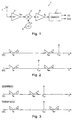
- Fig. 1 shows a receiver 1 for radio signals.
- the incoming radio signals are received at an antenna 2 and taken to a radio frequency tuner and amplifier 3.
- the amplified radio frequency signals are then down-converted to a predetermined intermediate frequency f IF in a frequency converter comprised of a mixer 4 and a local oscillator 5.
- Fig. 2 shows the spectrum of the various signals vs. frequency.
- f LO is shown as an arrow at a single frequency, whereas the RF and IF signals are shown as spectrums with a certain spectral distribution. (The specific distribution shown is not important, it may vary depending on the modulation scheme used).
- An L (for low) and H (for high) are used to indicate the position of each part of the RF spectral distribution.
- the RF spectrum is down-converted to the IF spectrum using the LO signal.
- the spectrum of the RF signal remains unaltered, except for the shift to a lower frequency (f IF ).
- the spectrum of the RF signal is switched, so that the H portion is moved to the low side, and the L portion is moved to the high side.
- the spectrum of the RF signal is replaced by the mirror of the same spectrum at IF (spectrum mirroring or sideband reversal).
- the intermediate frequency signal is fed from an IF amplifier and filter 6 to a demodulator 7.
- a demodulator 7 Very often this will be a quadrature demodulator, and in that case the outputs from the demodulator will be in the form of the two quadrature signals labelled I(t) and Q(t). These signals are then processed in decoding circuitry in the apparatus.
- this part of the apparatus is not relevant for the invention, it is not shown in the figure.
- the function of the quadrature demodulator will be described later.
- a receiver according to the invention is adapted to receive radio signals in at least two different frequency bands.
- multiband mobile telephones could be adapted to receive and/or transmit signals in the GSM900 band (900 MHz) and the GSM1800 band (1800 MHz). If the frequency of the local oscillator is selected above f RF for the lower band and below f RF for the higher band, as is shown in fig. 3, the frequencies of the local oscillator could be selected from the same range for both bands. However, as mentioned above, this will have the drawback that the sideband reversal will take place for the lower band. This means that when the receiver switches from one band to the other, a switch of sidebands will take place in the intermediate frequency signal, and such a switch is normally not allowable.
- the circuit may be modified as shown in fig. 4.
- an amplifier is provided for each band, i.e. an amplifier 8 for one band (e.g. GSM900) and an amplifier 9 for the other band (GSM1800).
- the input from the antenna 2 is passed through a diplexer 10, which is a combination of bandpass filters separating the two bands.
- a switch 11 selects which of the two amplified radio frequency signals is sent to the mixer 4.
- the circuit is similar to that of fig. 1.
- the function of the quadrature modulator and demodulator will be described in the following.
- the demodulator is used in the receiver and the modulator correspondingly in a transmitter.
- the function of the modulator is to move information from baseband up to a carrier which is the intermediate frequency (f IF ) in this case.
- the quadrature modulator is a special modulator, characterized by its ability to be used at both amplitude modulation (AM), phase modulation (PM) and frequency modulation (FM) and also at the digital equivalents PSK and FSK.
- the quadrature modulator is able to suppress the carrier itself and unwanted mixing products (spurious signals), a functionality which is often hard to achieve using other types of modulators.
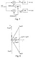
- the schematic of the quadrature modulator is shown in figure 5.
- Input signals to the modulator are the two signals I(t) and Q(t).
- (A.2) is the general expression for a modulated signal.
- A(t) is the amplitude of the modulated signal s(t)
- ⁇ ( t ) is the phase of s(t).
- the signal vector s ( t ) with length A ( t ) and angle ⁇ ( t ) is shown in figure 6.
- the function of the quadrature demodulator is to move information from the IF frequency in this case down to baseband. This is described through the diagram in figure 7.
- the high frequency terms are removed by means of the low-pass filter, and the result is the baseband signal I(t).
- Q(t) may be obtained similarly.
- phase ⁇ ( t ) changes sign when a switch is made between GSM900 and GSM1800.
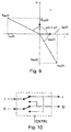
- the vector signal diagram shown in fig. 8 may be constructed from equations (A.13) and (A.14).
- phase ⁇ ( t ) changes as a function of time, the two vectors will rotate reversely.
- the sign of Q(t) when the band is switched between GSM900 and GSM1800.
- the same result is obtained by swapping the I and Q signals.
- the phase will rotate in the same direction for both GSM900 and GSM1800, but there will be a constant difference of 90° between the two bands, as illustrated in fig. 9.
- I ⁇ 900 ( t ) and Q ⁇ 900 ( t ) denotes the I- and Q-signals after the swapping.
- the swapping of the I and Q signals may be implemented with an analog switch circuitry, as shown in fig. 10, where the CNTRL input places the switch in the lower position for GSM900 (swap) and in the upper position for GSM1800 (no swap).
- the bits may be inverted after the differential decoder. This may be done in hardware or software.
- a configuration similar to that in fig. 10 may be used to invert the bitstream internally in the baseband unit.
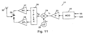
- the I and Q signals from the coding circuitry are fed to the modulator 22, which was shown in fig. 5.
- the modulated intermediate frequency signal is amplified in the amplifier 23 and then mixed with the signal from the local oscillator 25 in the mixer 24.
- the output from the mixer 24 contains signals in both radio frequency bands and in the diplexer they are divided between the two radio frequency amplifiers 27 and 28.
- a switch 29 selects which of the two signals is fed to the antenna 30.
- a sideband reversal occurs in the radio frequency signals when the transmitter shifts between the two bands. Again, it can be shown in the same way as above that this reversal effect may be compensated by a change of sign of the Q signal or by swapping the I and Q signals before they are fed to the modulator 22.
Abstract
Description
- The invention relates to a radio receiver adapted to receive radio signals in at least two frequency bands, said radio signals being modulated by information signals, said radio receiver comprising means for down-converting a received radio signal to an intermediate frequency signal by means of a local oscillator, and demodulating means for recovering the information signals from the intermediate frequency signal.
- The invention also relates to a corresponding radio transmitter adapted to transmit radio signals in at least two frequency bands, said radio transmitter comprising means for modulating an intermediate frequency signal by information signals, means for converting the intermediate frequency signal to a radio signal by means of a local oscillator, and means for transmitting said radio signal.
- In such receivers and transmitters, of which the superheterodyne receiver and corresponding transmitters are examples, the frequency of the local oscillator can be selected either above or below the frequencies of the relevant frequency bands. For each band the frequency of the oscillator should be variable over a range corresponding to the range of the band, because the difference in frequency between the radio signals and the local oscillator should be equal to the frequency of the intermediate signal, which has a very low bandwidth around a fixed frequency. However, in many situations the frequency bands cover a wide frequency range. This is the case for e.g. multiband mobile telephones. Such telephones could for instance be adapted to receive and/or transmit signals in the GSM900 band (900 MHz) and the GSM1800 band (1800 MHz). If the same local oscillator should be used for the two bands in this case, the oscillator should be variable over a range of at least 900 MHz, which would be very difficult to implement in practice. Therefore, it will normally be necessary to use a separate local oscillator for each band.
- However, the use of two or more separate local oscillators complicates the design of the receiver or the transmitter considerably, and, especially, it takes up more space, which is a critical point in mobile telephones, because much effort is devoted to reducing the size of the telephones.
- The object of the invention is, therefore, to provide a receiver and a transmitter of the above-mentioned type which are able to receive/transmit signals in the at least two frequency bands with the use of only one single local oscillator.
- In accordance with the invention, this object is achieved in that the frequency of the local oscillator is selected so that the frequencies of at least one of said frequency bands are above the frequency of the local oscillator, and the frequencies of at least one of said frequency bands are below the frequency of the local oscillator.
- When the frequency of the local oscillator is selected to be between the relevant frequency bands, i.e. above the frequencies of the lower band (e.g. 900 MHz) and below the frequencies of the upper band (1800 MHz), the range over which a single oscillator should be variable (i.e. the bandwidth of the oscillator) is reduced considerably. Therefore, it is possible to implement such an oscillator in practice.
- When the receiver or the transmitter, as stated in claims 2 and 6 respectively, is adapted to receive or transmit radio signals in only two frequency bands and the frequency of the local oscillator is selected in a range substantially halfway between the two frequency bands, the range over which the single oscillator should be variable is reduced even further to a range of substantially the same size as for each band, because approximately the same oscillator frequencies may be used for both bands. If, for instance, the two bands are the earlier mentioned GSM900 and GSM1800 bands the intermediate frequency could be selected to approximately 450 MHz, causing the frequency of the local oscillator to be in a range around 1350 MHz for both bands.
- In the receiver case, it is well known that the selection of a local oscillator frequency above the frequencies of the relevant frequency band for the received radio signals causes sideband reversal in the down-converted signal, so that the upper side band at radio frequency becomes the lower side band at the intermediate frequency, and vice versa. This side band reversal does not occur when the frequency of the local oscillator is below the frequencies of the radio frequency signals. When the local oscillator frequency is selected between the two bands, a switch from reception in one band to reception in the other band will therefore also cause a change of the side bands in the intermediate frequency signal. This change of sidebands must be compensated in the receiver, for instance in the demodulating means.
- When the demodulating means is a quadrature demodulator adapted to recover the information signals in the form of an In-phase signal (I signal) and a Quadrature-phase signal (Q signal), and when the modulation of the received radio signals is a phase modulation or a frequency modulation, this compensation may be implemented in one embodiment stated in claim 3, in that the receiver moreover comprises means for assigning one sign (+ or -) to the Q signal when the frequency of the received radio signal is below the frequency of the local oscillator, and the opposite sign when the frequency of the received radio signal is above the frequency of the local oscillator. It can be shown that in the quadrature demodulator the change of side bands means a change of the sign of the Q signal and, therefore, the change may be compensated by changing the sign back.
- Further, it can be shown that a change of sign of the Q signal is equivalent to swapping or exchanging the I signal and the Q signal. Therefore, in a preferred embodiment stated in claim 4, the compensation of the change of sidebands may be implemented in that the receiver moreover comprises means for keeping the I signal and the Q signal unchanged when the frequency of the received radio signal is above the frequency of the local oscillator, and for exchanging the I signal and the Q signal when the frequency of the received radio signal is below the frequency of the local oscillator.
- In the transmitter case a similar effect is present. The selection of a local oscillator frequency above the frequencies of the relevant frequency band for the transmitted radio signals, causes sideband reversal, so that the upper side band at intermediate frequency becomes the lower side band at the radio frequency, and vice versa. Also here, the side band reversal does not occur when the frequency of the local oscillator is below the frequencies of the radio frequency signals. When the local oscillator frequency is selected between the two bands, a switch from transmission in one band to transmission in the other band will therefore also cause a change of the side bands in the radio frequency signal. This change of sidebands must be compensated in the transmitter.
- When the modulating means is a quadrature modulator adapted to modulate the intermediate frequency signal by information signals in the form of an I signal and a Q signal, and when the modulation of the received radio signals is a phase modulation or a frequency modulation, this compensation may be implemented in one embodiment stated in claim 7, in that the transmitter moreover comprises means for assigning one sign (+ or -) to the Q signal when the frequency of the radio signal is below the frequency of the local oscillator, and the opposite sign when the frequency of the radio signal is above the frequency of the local oscillator. Like with the receiver it can be shown that in the quadrature modulator a change of the sign of the Q signal corresponds to a change of side bands in the intermediate frequency signal and, therefore, such a change can compensate the sideband change that occurs when the intermediate frequency signal is converted to the radio signal.
- It can be shown that a change of sign of the Q signal is equivalent to swapping or exchanging the I signal and the Q signal. Therefore, in a preferred embodiment stated in claim 8, the compensation of the change of sidebands may be implemented in that the transmitter moreover comprises means for keeping the I signal and the Q signal unchanged when the frequency of the radio signal is above the frequency of the local oscillator, and for exchanging the I signal and the Q signal when the frequency of the radio signal is below the frequency of the local oscillator.
- The invention will now be described more fully below with reference to the drawing, in which
- fig. 1 shows a receiver for radio signals according to the invention,
- fig. 2 shows the spectrum of signals with a local oscillator above and below the radio frequency band, respectively,
- fig. 3 shows the situation for GSM900 and GSM1800 signals,
- fig. 4 shows an alternative embodiment for a receiver according to the invention,
- fig. 5 shows the function of a quadrature modulator,
- fig. 6 shows a signal vector for the modulator of fig. 5,
- fig. 7 shows the function of a quadrature demodulator,
- fig. 8 shows a vector diagram of a change of sign of the Q signal,
- fig. 9 shows a vector diagram of the swapping of the I and Q signals,
- fig. 10 shows an implementation of the swapping of the I and Q signals, and
- fig. 11 shows a transmitter for radio signals according to the invention.
-
- Fig. 1 shows a receiver 1 for radio signals. The incoming radio signals are received at an antenna 2 and taken to a radio frequency tuner and amplifier 3. The amplified radio frequency signals are then down-converted to a predetermined intermediate frequency fIF in a frequency converter comprised of a mixer 4 and a local oscillator 5. The adjustable frequency fLO of the local oscillator 5 may be selected below or above the radio frequency fRF that is to be received, as is shown in fig. 2, so that
- Fig. 2 shows the spectrum of the various signals vs. frequency. fLO is shown as an arrow at a single frequency, whereas the RF and IF signals are shown as spectrums with a certain spectral distribution. (The specific distribution shown is not important, it may vary depending on the modulation scheme used). An L (for low) and H (for high) are used to indicate the position of each part of the RF spectral distribution.
- In both cases, the RF spectrum is down-converted to the IF spectrum using the LO signal. In the lower part of the figure where fLO is below fRF, the spectrum of the RF signal remains unaltered, except for the shift to a lower frequency (fIF). On the other hand, in the upper part of the figure where fLO is above fRF, the spectrum of the RF signal is switched, so that the H portion is moved to the low side, and the L portion is moved to the high side. In other words, the spectrum of the RF signal is replaced by the mirror of the same spectrum at IF (spectrum mirroring or sideband reversal).
- As will be seen from fig. 1, the intermediate frequency signal is fed from an IF amplifier and filter 6 to a demodulator 7. Very often this will be a quadrature demodulator, and in that case the outputs from the demodulator will be in the form of the two quadrature signals labelled I(t) and Q(t). These signals are then processed in decoding circuitry in the apparatus. However, as this part of the apparatus is not relevant for the invention, it is not shown in the figure. The function of the quadrature demodulator will be described later.
- A receiver according to the invention is adapted to receive radio signals in at least two different frequency bands. For instance multiband mobile telephones could be adapted to receive and/or transmit signals in the GSM900 band (900 MHz) and the GSM1800 band (1800 MHz). If the frequency of the local oscillator is selected above fRF for the lower band and below fRF for the higher band, as is shown in fig. 3, the frequencies of the local oscillator could be selected from the same range for both bands. However, as mentioned above, this will have the drawback that the sideband reversal will take place for the lower band. This means that when the receiver switches from one band to the other, a switch of sidebands will take place in the intermediate frequency signal, and such a switch is normally not allowable.
- Normally, it will be difficult for the radio frequency amplifier 3 to handle signals with such a great difference in frequency and, therefore, the circuit may be modified as shown in fig. 4. In this case, an amplifier is provided for each band, i.e. an amplifier 8 for one band (e.g. GSM900) and an amplifier 9 for the other band (GSM1800). The input from the antenna 2 is passed through a diplexer 10, which is a combination of bandpass filters separating the two bands. A switch 11 selects which of the two amplified radio frequency signals is sent to the mixer 4. In other respects the circuit is similar to that of fig. 1.
- The function of the quadrature modulator and demodulator will be described in the following. The demodulator is used in the receiver and the modulator correspondingly in a transmitter. The function of the modulator is to move information from baseband up to a carrier which is the intermediate frequency (fIF) in this case. The quadrature modulator is a special modulator, characterized by its ability to be used at both amplitude modulation (AM), phase modulation (PM) and frequency modulation (FM) and also at the digital equivalents PSK and FSK. Furthermore, the quadrature modulator is able to suppress the carrier itself and unwanted mixing products (spurious signals), a functionality which is often hard to achieve using other types of modulators.
- The schematic of the quadrature modulator is shown in figure 5. Input signals to the modulator are the two signals I(t) and Q(t). According to figure 5, the output s(t) of the quadrature modulator is given as (the angular frequency is defined as
- This expression may be rewritten as:
- (A.2) is the general expression for a modulated signal. In (A.2), A(t) is the amplitude of the modulated signal s(t), and ϕ(t) is the phase of s(t). The carrier frequency is
- Furthermore, it also follows from (A.2) that:
- From (A.3) and (A.4), s(t) may be expressed as a vector
- The function of the quadrature demodulator is to move information from the IF frequency in this case down to baseband. This is described through the diagram in figure 7.
- By considering one of the branches in fig. 7, the signal I ∼(t) may be calculated as
- The high frequency terms are removed by means of the low-pass filter, and the result is the baseband signal I(t). Q(t) may be obtained similarly.
- Remembering now the general expression for a modulated signal, the radio frequency signal received at the antenna 2 may be written as
- As seen above, the intermediate frequency is obtained by down-conversion using the local oscillator (LO) frequency:
- From (A.7) and (A.8), the input s(t) to the demodulator, i.e. the intermediate frequency signal, is given by:
- From (A.9) and (A.10), it is observed that the phase ϕ(t) changes sign when a switch is made between GSM900 and GSM1800.
- For GMSK and other phase modulation schemes, the amplitude A(t) is constant, and the I- and Q-signals are, therefore, given by (cf. (A.3) and (A.4)):
- Consequently, the following set of relations between the I and Q signals is obtained from (A.9) and (A.10):
- The vector signal diagram shown in fig. 8 may be constructed from equations (A.13) and (A.14).
- As the phase ϕ(t) changes as a function of time, the two vectors will rotate reversely. In order for the I and Q signals to be identical, it is necessary to change the sign of Q(t) when the band is switched between GSM900 and GSM1800. The same result is obtained by swapping the I and Q signals. In the latter case, the phase will rotate in the same direction for both GSM900 and GSM1800, but there will be a constant difference of 90° between the two bands, as illustrated in fig. 9.
- This can be seen from:
- A constant phase contribution is, however, not a problem, since the absolute phase is always unknown. Therefore, it is of no importance whether the sign of Q(t) is switched, or I(t) and Q(t) is swapped. Consequently, the sideband reversal in the down-converted signal may be compensated by swapping the I and Q signals at the output of the quadrature demodulator.
- The swapping of the I and Q signals may be implemented with an analog switch circuitry, as shown in fig. 10, where the CNTRL input places the switch in the lower position for GSM900 (swap) and in the upper position for GSM1800 (no swap).
- Alternatively, the bits may be inverted after the differential decoder. This may be done in hardware or software. A configuration similar to that in fig. 10 may be used to invert the bitstream internally in the baseband unit.
- Above, the situation has been described for a receiver. However, the problem and the solution are the same in the transmitter situation. One embodiment of a transmitter is shown in fig. 11.
- The I and Q signals from the coding circuitry are fed to the modulator 22, which was shown in fig. 5. The modulated intermediate frequency signal is amplified in the amplifier 23 and then mixed with the signal from the local oscillator 25 in the mixer 24. The output from the mixer 24 contains signals in both radio frequency bands and in the diplexer they are divided between the two radio frequency amplifiers 27 and 28. Finally, a switch 29 selects which of the two signals is fed to the antenna 30. Also here, a sideband reversal occurs in the radio frequency signals when the transmitter shifts between the two bands. Again, it can be shown in the same way as above that this reversal effect may be compensated by a change of sign of the Q signal or by swapping the I and Q signals before they are fed to the modulator 22.
- Although a preferred embodiment of the present invention has been described and shown, the invention is not restricted to it, but may also be embodied in other ways within the subject-matter defined in the following claims. For instance the principle may also be used in units adapted for more than two frequency bands.
Claims (8)
- A radio receiver (1) adapted to receive radio signals in at least two frequency bands, said radio signals being modulated by information signals, said radio receiver comprising means (4, 5) for down-converting a received radio signal to an intermediate frequency signal by means of a local oscillator (5), and demodulating means (7) for recovering the information signals from the intermediate-frequency signal,
characterized in that the frequency of the local oscillator (5) is selected so that the frequencies of at least one of said frequency bands are above the frequency of the local oscillator, and the frequencies of at least one of said frequency bands are below the frequency of the local oscillator. - A radio receiver according to claim 1, adapted to receive radio signals in two frequency bands, characterized in that the frequency of the local oscillator (5) is selected in a range substantially halfway between the two frequency bands.
- A radio receiver according to claim 1 or 2, wherein the modulation of the received radio signals is a phase modulation or a frequency modulation, characterized in that said demodulating means is a quadrature demodulator (7) adapted to recover the information signals in the form of an In-phase signal and a Quadrature-phase signal, and that the receiver moreover comprises means for assigning one sign (+ or -) to the Quadrature-phase signal when the frequency of the received radio signal is below the frequency of the local oscillator, and the opposite sign when the frequency of the received radio signal is above the frequency of the local oscillator.
- A radio receiver according to claim 1 or 2, wherein the modulation of the received radio signals is a phase modulation or a frequency modulation, characterized in that said demodulating means is a quadrature demodulator (7) adapted to recover the information signals in the form of an In-phase signal and a Quadrature-phase signal, and that the receiver moreover comprises means for keeping the In-phase signal and the Quadrature-phase signal unchanged when the frequency of the received radio signal is above the frequency of the local oscillator, and for exchanging the In-phase signal and the Quadrature-phase signal when the frequency of the received radio signal is below the frequency of the local oscillator.
- A radio transmitter (21) adapted to transmit radio signals in at least two frequency bands, said radio transmitter comprising means (22) for modulating an intermediate frequency signal by information signals, means (24, 25) for converting the intermediate frequency signal to a radio signal by means of a local oscillator (25), and means (30) for transmitting said radio signal,
characterized in that the frequency of the local oscillator (25) is selected so that the frequencies of at least one of said frequency bands are above the frequency of the local oscillator, and the frequencies of at least one of said frequency bands are below the frequency of the local oscillator. - A radio transmitter according to claim 5, and adapted to transmit radio signals in two frequency bands,
characterized in that the frequency of the local oscillator (25) is selected in a range substantially halfway between the two frequency bands. - A radio transmitter according to claim 5 or 6, wherein the modulation is a phase modulation or a frequency modulation, characterized in that said modulating means is a quadrature modulator (22) adapted to modulate the intermediate frequency signal by information signals in the form of an In-phase signal and a Quadrature-phase signal, and that the transmitter moreover comprises means for assigning one sign (+ or -) to the Quadrature-phase signal when the frequency of the radio signal is below the frequency of the local oscillator, and the opposite sign when the frequency of the radio signal is above the frequency of the local oscillator.
- A radio transmitter according to claim 5 or 6, wherein the modulation is a phase modulation or a frequency modulation, characterized in that said modulating means is a quadrature modulator (22) adapted to modulate the intermediate frequency signal by information signals in the form of an In-phase signal and a Quadrature-phase signal, and that the transmitter moreover comprises means for keeping the In-phase signal and the Quadrature-phase signal unchanged when the frequency of the radio signal is above the frequency of the local oscillator, and for exchanging the In-phase signal and the Quadrature-phase signal when the frequency of the radio signal is below the frequency of the local oscillator.
Priority Applications (4)
| Application Number | Priority Date | Filing Date | Title |
|---|---|---|---|
| DK98101136T DK0932251T3 (en) | 1998-01-23 | 1998-01-23 | Radio transmitter and radio receiver |
| EP98101136A EP0932251B1 (en) | 1998-01-23 | 1998-01-23 | A radio receiver and a radio transmitter |
| DE69829835T DE69829835T2 (en) | 1998-01-23 | 1998-01-23 | Radio transmitter and radio receiver |
| US09/235,662 US6373883B1 (en) | 1998-01-23 | 1999-01-22 | Radio receiver and a radio transmitter |
Applications Claiming Priority (1)
| Application Number | Priority Date | Filing Date | Title |
|---|---|---|---|
| EP98101136A EP0932251B1 (en) | 1998-01-23 | 1998-01-23 | A radio receiver and a radio transmitter |
Publications (2)
| Publication Number | Publication Date |
|---|---|
| EP0932251A1 true EP0932251A1 (en) | 1999-07-28 |
| EP0932251B1 EP0932251B1 (en) | 2005-04-20 |
Family
ID=8231298
Family Applications (1)
| Application Number | Title | Priority Date | Filing Date |
|---|---|---|---|
| EP98101136A Expired - Lifetime EP0932251B1 (en) | 1998-01-23 | 1998-01-23 | A radio receiver and a radio transmitter |
Country Status (4)
| Country | Link |
|---|---|
| US (1) | US6373883B1 (en) |
| EP (1) | EP0932251B1 (en) |
| DE (1) | DE69829835T2 (en) |
| DK (1) | DK0932251T3 (en) |
Cited By (2)
| Publication number | Priority date | Publication date | Assignee | Title |
|---|---|---|---|---|
| EP1075083A1 (en) * | 1999-07-29 | 2001-02-07 | Bose Corporation | Local oscillator |
| EP3105856A4 (en) * | 2014-02-12 | 2017-09-13 | Telefonaktiebolaget LM Ericsson (publ) | Method and arrangements in multi-band receivers |
Families Citing this family (17)
| Publication number | Priority date | Publication date | Assignee | Title |
|---|---|---|---|---|
| JP2001008118A (en) * | 1999-06-22 | 2001-01-12 | Alps Electric Co Ltd | Digital television tuner |
| US6510317B1 (en) * | 1999-11-04 | 2003-01-21 | Xm Satellite Radio, Inc. | Satellite digital audio radio service tuner architecture for reception of satellite and terrestrial signals |
| US6728527B2 (en) * | 2001-07-10 | 2004-04-27 | Asulab S.A. | Double up-conversion modulator |
| US6950478B1 (en) * | 2001-08-02 | 2005-09-27 | Texas Instruments Incorporated | Transmitter and method having a low sampling frequency for digital to analog conversion |
| US20050143031A1 (en) * | 2002-02-06 | 2005-06-30 | Oswald Moonen | Multi-band receiver |
| US7415243B2 (en) | 2003-03-27 | 2008-08-19 | Honda Giken Kogyo Kabushiki Kaisha | System, method and computer program product for receiving data from a satellite radio network |
| US7849149B2 (en) | 2004-04-06 | 2010-12-07 | Honda Motor Co., Ltd. | Method and system for controlling the exchange of vehicle related messages |
| US8041779B2 (en) * | 2003-12-15 | 2011-10-18 | Honda Motor Co., Ltd. | Method and system for facilitating the exchange of information between a vehicle and a remote location |
| US7818380B2 (en) * | 2003-12-15 | 2010-10-19 | Honda Motor Co., Ltd. | Method and system for broadcasting safety messages to a vehicle |
| US11152971B2 (en) * | 2004-02-02 | 2021-10-19 | Charles Abraham | Frequency modulated OFDM over various communication media |
| US7518530B2 (en) * | 2004-07-19 | 2009-04-14 | Honda Motor Co., Ltd. | Method and system for broadcasting audio and visual display messages to a vehicle |
| US7391317B2 (en) * | 2004-09-08 | 2008-06-24 | Satius, Inc. | Apparatus and method for transmitting digital data over various communication media |
| US7643788B2 (en) * | 2004-09-22 | 2010-01-05 | Honda Motor Co., Ltd. | Method and system for broadcasting data messages to a vehicle |
| US7562049B2 (en) * | 2005-03-29 | 2009-07-14 | Honda Motor Co., Ltd. | Payment system and method for data broadcasted from a remote location to vehicles |
| US7949330B2 (en) | 2005-08-25 | 2011-05-24 | Honda Motor Co., Ltd. | System and method for providing weather warnings and alerts |
| US7668653B2 (en) | 2007-05-31 | 2010-02-23 | Honda Motor Co., Ltd. | System and method for selectively filtering and providing event program information |
| US8099308B2 (en) | 2007-10-02 | 2012-01-17 | Honda Motor Co., Ltd. | Method and system for vehicle service appointments based on diagnostic trouble codes |
Citations (4)
| Publication number | Priority date | Publication date | Assignee | Title |
|---|---|---|---|---|
| EP0651522A1 (en) * | 1993-11-01 | 1995-05-03 | Nokia Mobile Phones Ltd. | Image rejection frequency converter as multi-band receiver |
| EP0653851A2 (en) * | 1993-11-12 | 1995-05-17 | Philips Patentverwaltung GmbH | Multiband radio transceiver |
| US5442655A (en) * | 1992-06-03 | 1995-08-15 | Fujitsu Limited | DC cancellation and restoration in receiving apparatus |
| EP0792027A1 (en) * | 1996-02-21 | 1997-08-27 | Koninklijke Philips Electronics N.V. | Multi-band radio-telephone apparatus |
Family Cites Families (3)
| Publication number | Priority date | Publication date | Assignee | Title |
|---|---|---|---|---|
| GB9501243D0 (en) * | 1995-01-23 | 1995-03-15 | Rca Thomson Licensing Corp | Local oscillator using digital handswitching |
| JPH09275358A (en) * | 1996-04-08 | 1997-10-21 | Matsushita Electric Ind Co Ltd | Plural-band mobile radio equipment |
| US6208875B1 (en) * | 1998-04-08 | 2001-03-27 | Conexant Systems, Inc. | RF architecture for cellular dual-band telephones |
-
1998
- 1998-01-23 EP EP98101136A patent/EP0932251B1/en not_active Expired - Lifetime
- 1998-01-23 DE DE69829835T patent/DE69829835T2/en not_active Expired - Lifetime
- 1998-01-23 DK DK98101136T patent/DK0932251T3/en active
-
1999
- 1999-01-22 US US09/235,662 patent/US6373883B1/en not_active Expired - Fee Related
Patent Citations (4)
| Publication number | Priority date | Publication date | Assignee | Title |
|---|---|---|---|---|
| US5442655A (en) * | 1992-06-03 | 1995-08-15 | Fujitsu Limited | DC cancellation and restoration in receiving apparatus |
| EP0651522A1 (en) * | 1993-11-01 | 1995-05-03 | Nokia Mobile Phones Ltd. | Image rejection frequency converter as multi-band receiver |
| EP0653851A2 (en) * | 1993-11-12 | 1995-05-17 | Philips Patentverwaltung GmbH | Multiband radio transceiver |
| EP0792027A1 (en) * | 1996-02-21 | 1997-08-27 | Koninklijke Philips Electronics N.V. | Multi-band radio-telephone apparatus |
Non-Patent Citations (1)
| Title |
|---|
| DUPLESSIS P ET AL: "TOWARDS A COMBINED GSM 900 DCS 1800 SYSTEM", PROCEEDINGS OF THE NORDIC SEMINAR ON DIGITAL MOBILE RADIO COMMUNICATIONS, HELSINKI, DEC. 1 - 3, 1992, no. SEMINAR 5, 1 December 1992 (1992-12-01), TELECOM FINLAND, pages 89 - 92, XP000457840 * |
Cited By (3)
| Publication number | Priority date | Publication date | Assignee | Title |
|---|---|---|---|---|
| EP1075083A1 (en) * | 1999-07-29 | 2001-02-07 | Bose Corporation | Local oscillator |
| EP3105856A4 (en) * | 2014-02-12 | 2017-09-13 | Telefonaktiebolaget LM Ericsson (publ) | Method and arrangements in multi-band receivers |
| US9843435B2 (en) | 2014-02-12 | 2017-12-12 | Telefonaktiebolaget Lm Ericsson (Publ) | Method and arrangements in multi-band receivers |
Also Published As
| Publication number | Publication date |
|---|---|
| EP0932251B1 (en) | 2005-04-20 |
| US6373883B1 (en) | 2002-04-16 |
| DE69829835D1 (en) | 2005-05-25 |
| DK0932251T3 (en) | 2005-05-23 |
| DE69829835T2 (en) | 2005-11-24 |
Similar Documents
| Publication | Publication Date | Title |
|---|---|---|
| EP0932251B1 (en) | A radio receiver and a radio transmitter | |
| US5495500A (en) | Homodyne radio architecture for direct sequence spread spectrum data reception | |
| US6334051B1 (en) | Direct conversion receiver with wide band analog frequency conversion front end and digital demodulating and selecting back end | |
| JP3647894B2 (en) | Intermediate frequency FM receiver using analog oversampling to increase signal bandwidth | |
| US7345551B2 (en) | Frequency synthesizer for mixing reference frequencies | |
| US5412351A (en) | Quadrature local oscillator network | |
| US6937670B2 (en) | Digital tuner | |
| JPH0382248A (en) | 90× phase shifter and data receiver | |
| WO2000076060A1 (en) | Dual-band image rejection mixer | |
| US4622694A (en) | Transmission system for TV signals on radio links | |
| US7046979B2 (en) | Receiver for rejecting image signal | |
| EP0875988B1 (en) | Interference suppression in RF signals | |
| AU2001247242B2 (en) | A novel low cost/low power analog transceiver architecture | |
| KR20000070321A (en) | Demodulation unit and method of demodulating a quadrature signal | |
| US7120202B2 (en) | Wireless communication apparatus | |
| JP4738604B2 (en) | Demodulator and demodulation method | |
| JP3993573B2 (en) | Wireless communication device compatible with multiple wireless systems | |
| JP3743046B2 (en) | Direct conversion receiver | |
| US7236541B1 (en) | Translation loop modulator | |
| JP3128222B2 (en) | Confidential communication system | |
| JP3153158B2 (en) | Digital modulated wave transmission / reception system and transmission / reception device | |
| KR100285756B1 (en) | Apparatus for tracking carrier in wireless transfer system | |
| WO1999000910A1 (en) | Communication device | |
| TW417363B (en) | Dual-conversion RF transmitting/receiving system | |
| JP2001275059A (en) | Television tuner |
Legal Events
| Date | Code | Title | Description |
|---|---|---|---|
| PUAI | Public reference made under article 153(3) epc to a published international application that has entered the european phase |
Free format text: ORIGINAL CODE: 0009012 |
|
| AK | Designated contracting states |
Kind code of ref document: A1 Designated state(s): DE DK FI GB SE |
|
| 17P | Request for examination filed |
Effective date: 20000128 |
|
| AKX | Designation fees paid |
Free format text: DE DK FI GB SE |
|
| RAP1 | Party data changed (applicant data changed or rights of an application transferred) |
Owner name: SIEMENS AKTIENGESELLSCHAFT |
|
| 17Q | First examination report despatched |
Effective date: 20040803 |
|
| GRAP | Despatch of communication of intention to grant a patent |
Free format text: ORIGINAL CODE: EPIDOSNIGR1 |
|
| GRAS | Grant fee paid |
Free format text: ORIGINAL CODE: EPIDOSNIGR3 |
|
| GRAA | (expected) grant |
Free format text: ORIGINAL CODE: 0009210 |
|
| AK | Designated contracting states |
Kind code of ref document: B1 Designated state(s): DE DK FI GB SE |
|
| REG | Reference to a national code |
Ref country code: GB Ref legal event code: FG4D |
|
| REG | Reference to a national code |
Ref country code: DK Ref legal event code: T3 |
|
| REF | Corresponds to: |
Ref document number: 69829835 Country of ref document: DE Date of ref document: 20050525 Kind code of ref document: P |
|
| REG | Reference to a national code |
Ref country code: SE Ref legal event code: TRGR |
|
| PLBE | No opposition filed within time limit |
Free format text: ORIGINAL CODE: 0009261 |
|
| STAA | Information on the status of an ep patent application or granted ep patent |
Free format text: STATUS: NO OPPOSITION FILED WITHIN TIME LIMIT |
|
| 26N | No opposition filed |
Effective date: 20060123 |
|
| PGFP | Annual fee paid to national office [announced via postgrant information from national office to epo] |
Ref country code: DK Payment date: 20070112 Year of fee payment: 10 |
|
| REG | Reference to a national code |
Ref country code: DK Ref legal event code: EBP |
|
| PGFP | Annual fee paid to national office [announced via postgrant information from national office to epo] |
Ref country code: FI Payment date: 20080710 Year of fee payment: 11 |
|
| PG25 | Lapsed in a contracting state [announced via postgrant information from national office to epo] |
Ref country code: DK Free format text: LAPSE BECAUSE OF NON-PAYMENT OF DUE FEES Effective date: 20080131 |
|
| PGFP | Annual fee paid to national office [announced via postgrant information from national office to epo] |
Ref country code: SE Payment date: 20080729 Year of fee payment: 11 |
|
| EUG | Se: european patent has lapsed | ||
| PG25 | Lapsed in a contracting state [announced via postgrant information from national office to epo] |
Ref country code: FI Free format text: LAPSE BECAUSE OF NON-PAYMENT OF DUE FEES Effective date: 20090123 |
|
| REG | Reference to a national code |
Ref country code: GB Ref legal event code: 732E Free format text: REGISTERED BETWEEN 20100812 AND 20100818 |
|
| REG | Reference to a national code |
Ref country code: GB Ref legal event code: 732E Free format text: REGISTERED BETWEEN 20100826 AND 20100901 |
|
| REG | Reference to a national code |
Ref country code: GB Ref legal event code: 732E Free format text: REGISTERED BETWEEN 20110407 AND 20110413 |
|
| PG25 | Lapsed in a contracting state [announced via postgrant information from national office to epo] |
Ref country code: SE Free format text: LAPSE BECAUSE OF NON-PAYMENT OF DUE FEES Effective date: 20090124 |
|
| REG | Reference to a national code |
Ref country code: DE Ref legal event code: R081 Ref document number: 69829835 Country of ref document: DE Owner name: QUALCOMM INCORPORATED, SAN DIEGO, US Free format text: FORMER OWNER: PALM, INC. (N.D.GES. D. STAATES DELAWARE), SUNNYVALE, CALIF., US Effective date: 20110406 Ref country code: DE Ref legal event code: R081 Ref document number: 69829835 Country of ref document: DE Owner name: QUALCOMM INCORPORATED, US Free format text: FORMER OWNER: PALM, INC. (N.D.GES. D. STAATES DELAWARE), SUNNYVALE, US Effective date: 20110406 |
|
| REG | Reference to a national code |
Ref country code: DE Ref legal event code: R082 Ref document number: 69829835 Country of ref document: DE Representative=s name: SAMSON & PARTNER, PATENTANWAELTE, DE |
|
| REG | Reference to a national code |
Ref country code: DE Ref legal event code: R082 Ref document number: 69829835 Country of ref document: DE Representative=s name: MAUCHER JENKINS, DE Effective date: 20140307 Ref country code: DE Ref legal event code: R082 Ref document number: 69829835 Country of ref document: DE Representative=s name: SAMSON & PARTNER PATENTANWAELTE MBB, DE Effective date: 20140307 Ref country code: DE Ref legal event code: R082 Ref document number: 69829835 Country of ref document: DE Representative=s name: SAMSON & PARTNER, PATENTANWAELTE, DE Effective date: 20140307 Ref country code: DE Ref legal event code: R081 Ref document number: 69829835 Country of ref document: DE Owner name: QUALCOMM INCORPORATED, SAN DIEGO, US Free format text: FORMER OWNER: HEWLETT-PACKARD DEVELOPMENT COMPANY, L.P., HOUSTON, TEX., US Effective date: 20140307 Ref country code: DE Ref legal event code: R081 Ref document number: 69829835 Country of ref document: DE Owner name: QUALCOMM INCORPORATED, US Free format text: FORMER OWNER: HEWLETT-PACKARD DEVELOPMENT CO., L.P., HOUSTON, US Effective date: 20140307 |
|
| REG | Reference to a national code |
Ref country code: GB Ref legal event code: 732E Free format text: REGISTERED BETWEEN 20140508 AND 20140514 |
|
| PGFP | Annual fee paid to national office [announced via postgrant information from national office to epo] |
Ref country code: GB Payment date: 20161228 Year of fee payment: 20 |
|
| PGFP | Annual fee paid to national office [announced via postgrant information from national office to epo] |
Ref country code: DE Payment date: 20170131 Year of fee payment: 20 |
|
| REG | Reference to a national code |
Ref country code: DE Ref legal event code: R082 Ref document number: 69829835 Country of ref document: DE Representative=s name: MAUCHER JENKINS, DE |
|
| REG | Reference to a national code |
Ref country code: DE Ref legal event code: R071 Ref document number: 69829835 Country of ref document: DE |
|
| REG | Reference to a national code |
Ref country code: GB Ref legal event code: PE20 Expiry date: 20180122 |
|
| PG25 | Lapsed in a contracting state [announced via postgrant information from national office to epo] |
Ref country code: GB Free format text: LAPSE BECAUSE OF EXPIRATION OF PROTECTION Effective date: 20180122 |