EP0616411A1 - Quick charge method for battery and integrated circuit for performing the method - Google Patents
Quick charge method for battery and integrated circuit for performing the method Download PDFInfo
- Publication number
- EP0616411A1 EP0616411A1 EP94400575A EP94400575A EP0616411A1 EP 0616411 A1 EP0616411 A1 EP 0616411A1 EP 94400575 A EP94400575 A EP 94400575A EP 94400575 A EP94400575 A EP 94400575A EP 0616411 A1 EP0616411 A1 EP 0616411A1
- Authority
- EP
- European Patent Office
- Prior art keywords
- battery
- voltage
- charge
- signal
- variation
- Prior art date
- Legal status (The legal status is an assumption and is not a legal conclusion. Google has not performed a legal analysis and makes no representation as to the accuracy of the status listed.)
- Granted
Links
Images


Classifications
-
- H—ELECTRICITY
- H02—GENERATION; CONVERSION OR DISTRIBUTION OF ELECTRIC POWER
- H02J—CIRCUIT ARRANGEMENTS OR SYSTEMS FOR SUPPLYING OR DISTRIBUTING ELECTRIC POWER; SYSTEMS FOR STORING ELECTRIC ENERGY
- H02J7/00—Circuit arrangements for charging or depolarising batteries or for supplying loads from batteries
- H02J7/007—Regulation of charging or discharging current or voltage
- H02J7/00712—Regulation of charging or discharging current or voltage the cycle being controlled or terminated in response to electric parameters
- H02J7/007182—Regulation of charging or discharging current or voltage the cycle being controlled or terminated in response to electric parameters in response to battery voltage
- H02J7/007184—Regulation of charging or discharging current or voltage the cycle being controlled or terminated in response to electric parameters in response to battery voltage in response to battery voltage gradient
Definitions
- the present invention relates to a method for rapidly charging a battery, in particular a battery of the cadmium-nickel (CdNi) or nickel-metal-hydride (NiMh) type. This method can nevertheless be useful for charging all types of battery in a rapid manner if the charging characteristics of these batteries are similar.
- the invention also relates to an improved integrated circuit capable of implementing the method of the invention.
- delta V or negative delta V method.
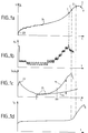
- This method uses the characteristic curve of charge voltage of a battery, for example of the cadmium-nickel type. This curve is shown in Figure 1a.
- an electronic control circuit which then decides to stop the load.
- a more recent method is to measure the temperature of the battery, and to decide to stop the load when the rate of temperature increase exceeds a certain threshold. Indeed, we see, in Figure 1d, that the temperature remains constant for almost the entire charge. It begins to increase towards the end more and more strongly, especially in the last part of the curve. With this temperature measurement method, the load is stopped at point B, at a time when the temperature increases at a speed greater than a certain rate fixed in advance.
- a disadvantage of this method is that it requires a temperature sensor on each battery, as well as one or two additional contacts to the battery-charger connection. This is sometimes prohibitively expensive.
- a second drawback of this method is that the temperature propagates slowly from the core of the battery to its periphery and then to the sensor. In other words, when the charge is stopped, the battery has already had time to overheat.
- the object of the invention is to remedy the drawbacks mentioned by proposing a method, and an integrated circuit implementing this method, which make it possible to stop the charges of the batteries before the time when an overload, or even an overheating, could have been detected.
- the principle of the invention resides in the monitoring of the curve of variation of charge of the battery as a function of time. In fact, it has been observed in the invention that the voltage across the terminals of the battery increases more and more quickly and then, before reaching its maximum, begins to grow less quickly. We then had the idea, rather than using the actual voltage signal, to use a derivative, a variation, of this voltage signal. As long as this derivative, this variation, increases from one period to the next, we are in a situation without risk for the battery.
- the invention also relates to an integrated circuit provided with circuits and connections for measuring and controlling the rapid charge of a battery, comprising a microprocessor in relation to a memory.
- program characterized in that the program contained in this memory includes instructions corresponding to the steps of the method.
- FIG. 2 shows an integrated circuit 1 usable for implementing the method of the invention in order to charge a battery 2 from a current source 3.
- the current source 3 is represented here in a schematic manner with a transformer 4, a rectifier bridge 5 and a filter 6.
- Figure 4 will show a preferred variant embodiment of a circuit delivering a strong and constant load current.
- the battery 2 is connected by connections 7 and 8 to the charging circuit 3.
- the charging voltage of the battery is measured periodically with an analog to digital converter 9 during charging.
- This voltage is taken for example by connecting the analog digital converter 9 to connections 7 and 8.
- the analog digital converter 9 produces a measurement signal in binary mode available on its outputs 10 to 11.
- the outputs 10 to 11 of the analog digital converter 9 are connected by a bus 12 of the integrated circuit to a microprocessor 13 which manages the measurements and which produces a signal for stopping the load when the load is nominal.
- This signal for stopping the charge is for example a logic level available on a connection 14 at the output of the microprocessor 13 and terminating on a passing transistor 15 interposed in one of the connections 7 or 8. It is possible to adopt other load stop circuits: the one shown is only shown for information.
- the rectifier 5 can be a rectifier controlled by the microprocessor 13, in which case this rectifier 5 can, when the time comes, be invalidated.
- the microprocessor 13 is related to a program memory 16 of the non-volatile type (ROM). This memory 16 contains the instructions corresponding to the execution of the steps of the method. When the assembly is powered up, the microprocessor 13 can transfer the instructions contained in the memory 16 into a working memory 17 of the random access type also connected to the microprocessor 13. Depending on the type of microprocessor used, it can also be it is possible to execute the instructions read directly from the non-volatile memory 16.
- the volatile random access memory 17 also includes a set of registers which can be used to store the values of the working variables produced in the different phases of the process.
- the microprocessor 13 can finally be connected to an alarm circuit 18 comprising for example a lamp or a loudspeaker.
- the microprocessor 13 receives a clock signal H and also transmits, on a control bus 19, orders to the memories 16 and 17 and the analog-to-digital converter 9.
- the timing of the sampling carried out by the analog to digital converter 9 is caused by the microprocessor 13. In one example, this timing is of the order of one measurement per second.
- the analog-to-digital converter 9 samples the measurement of the voltage V in step 20.1 and produces a first digitized measurement signal Y n .
- a derivative or pseudo derivative d n Y n - Y nk is calculated from Y n .
- the signal d n called the second signal, is shown in Figure 1b.
- the signal d n which represents the variation of the battery voltage, undergoes staircase steps which are due to the quantification of the analog-to-digital converter 9. This signal is not easily exploitable given its erratic nature. However, one could imagine using it as to locate its maximum corresponding to the inflection point I in Figure 1a. It would suffice to identify the instant when this signal d n would become greater than a predetermined threshold.
- the constant k is for example fixed at 10.
- the second signal thus produced, d n is representative of the variation of the charging voltage during a period.
- the duration of this period is k samples. It is not exactly a derivative, but a simple approximation which has the advantage of being easily calculated by the microprocessor 13 taking into account that there is only one subtraction to do.
- a division by k is omitted since k is constant throughout the process.
- the value k can be chosen according to the type of batteries to be charged.
- the last k measured samples Y n to Y nk will be permanently stored in memory 17.
- a new sample is measured, it takes the place of the last sample Y n measured, this takes the place of the sample Y n-1 , and so on, the old disappearing sample Y nk .
- This is represented diagrammatically in FIG. 2 by arrows for shifting the content of the registers of the memory 17. In practice, this can be done differently by simply modifying the addresses of the useful registers.
- the signal dn is noisy due to the quantization in the analog-to-digital converter 9.
- the quantization problems are solved by smoothing the derivative to obtain a smooth derivative which is more easily exploitable.
- This smoothing corresponds to a damping applied to the quantized signal dn so as to produce a third signal z n shown in Figure 1c.
- This method gives a smoothing by calculation of the average of the derivative dn.
- the triggering thus described of the stop of the charge is automatic when one is in the significant right part of the curve of the voltage V.
- a problem can arise which consists in distinguishing the top of the smoothed derivative Z n , corresponding to the point C, on the one hand a vertex 22 located at the very beginning of the curve and on the other hand many other local maximums 25 located in the middle part of the curve.
- the vertex 22 located at the start of the curve is created by the conditions of initialization of the variables at zero at the start of the charge and by a decrease in the slope of the battery voltage at the start of the charge. In fact, during the first seconds of connection, the voltage across the battery rises very quickly: rise 23 Figure 1a. Then it goes back down, causing the summit 22 of the derivative to pass.
- the local maximums 25 are themselves consecutive to the quantification of the analog-digital converter 9 in an area where the slope of the curve of the charging voltage is constant, area 24 in FIG. 1a.
- a test 26 carried out after step 20.3, it is ensured that the duration since the start of the charge is greater than a basic duration T.
- the basic duration T will be equal to one hundred seconds: equal to one hundred times the duration which separates two successive samples.
- step 28 the calculation of the variable w n is undertaken as indicated in step 28, making sure that w n is equal to 0.996 w n-1 + 0.004 z not
- step 27 This amounts to filtering the value of the derivative over approximately one thousand samples (while keeping only k samples in memory).
- step 27 makes it possible to arbitrarily fix the highly damped derivative w n quickly, at a significant value without having to wait for it to go up there.
- step 29 This comparison is undertaken in the form of a report.
- test 29 will be considered negative and the load will be allowed to continue. We retained fifty percent but obviously we could retain another report, for example twenty five percent or even possibly seventy or eighty percent. If necessary we could use this test, to stop charging.
- test 29 As soon as the result of test 29 becomes positive, we are in the significant measurement phase and we can, by carrying out test 21, locate the maximum value z n .
- test 29 When the test 29 is positive, it is considered that the battery voltage has entered a phase of rapid increase in its slope. This only occurs in this area of the charge curve, regardless of the type of battery. This makes it possible to isolate the period, located to the right of a duration XX from which the smoothed derivative z n no longer has local maxima or other singularities. It is therefore easy from this point to detect the vertex of this smoothed derivative.
- FIG. 3 shows a preferred embodiment of such a current source stable over time and independent of the variation of the supply voltage.
- a voltage stabilized supply not shown, supplies the integrated circuit 1 at 12 volts, as well as a circuit 30, of the LM 317 type from SGS THIOMSON MICROELECTRONICS.
- This circuit 30 has two outputs 31 and 32, called Vout and Adjust, between which a setting resistor 33 can be put in parallel.
- the resistor 33 makes it possible to impose on battery 2 a voltage available at output 32 and an equal current to the ratio of the voltage difference between outputs 31 and 32 by the value of resistor 33.
Abstract
Description
La présente invention a pour objet un procédé de charge rapide d'une batterie, notamment d'une batterie de type cadmium-nickel (CdNi) ou de type nickel-metal-hydrure (NiMh). Ce procédé peut néanmoins être utile à charger tous types de batterie d'une manière rapide si les caractéristiques de charge de ces batteries sont similaires. L'invention à également pour objet un circuit intégré perfectionné apte à mettre en oeuvre le procédé de l'invention.The present invention relates to a method for rapidly charging a battery, in particular a battery of the cadmium-nickel (CdNi) or nickel-metal-hydride (NiMh) type. This method can nevertheless be useful for charging all types of battery in a rapid manner if the charging characteristics of these batteries are similar. The invention also relates to an improved integrated circuit capable of implementing the method of the invention.
Pour charger rapidement une batterie CdNi ou NiMh, il faut lui injecter un courant constant, d'autant plus important que l'on désire que la charge soit rapide. Par exemple, un courant de trois ampères permet de charger une batterie de un ampère/heure en un peu plus de vingt minutes. La difficulté consiste à déterminer quand arrêter la charge, sachant que quelques minutes de surcharge diminuent, par échauffement, la durée de vie de la batterie. Quelques dizaine de minutes excédentaires peuvent la mettre hors service ou la détruire. Le procédé de l'invention permet de stopper la charge avant que l'échauffement n'intervienne, et donc avant d'être en surcharge, cela sans nécessiter de capteur de température coûteux.To quickly charge a CdNi or NiMh battery, you must inject it with a constant current, all the more important if you want the charge to be fast. For example, a current of three amperes can charge a battery of one ampere / hour in just over twenty minutes. The difficulty is to determine when to stop charging, knowing that a few minutes of overcharging shorten the life of the battery by heating up. A few extra ten minutes can put it out of service or destroy it. The method of the invention makes it possible to stop the load before the heating occurs, and therefore before being overloaded, without requiring an expensive temperature sensor.
De nombreux procédés existent pour déterminer la fin de charge rapide d'un batterie lorsque celle-ci a atteint sa charge nominale. Ces procédés sont caractérisés par leur temps de réaction après la fin de charge. Celui-ci doit être le plus court possible. Ces procédés sont également caractérisés par leur fiabilité, leur répétitivité, et leur coût.Many methods exist for determining the end of rapid charging of a battery when it has reached its nominal charge. These processes are characterized by their reaction time after the charge has ended. This should be as short as possible. These processes are also characterized by their reliability, their repeatability, and their cost.
La méthode la plus classique est la méthode dite - delta V, ou delta V négatif. Cette méthode utilise la courbe caractéristique de tension de charge d'une batterie, par exemple de type cadmium-nickel. Cette courbe est représentée sur la Figure 1a. Quand la batterie est pleine, et même légèrement surchargée, la tension redescend légèrement, après avoir crû continuement pendant la charge. Cette baisse de tension est détectée par un circuit électronique de contrôle qui décide alors d'arrêter la charge. On peut par exemple détecter un delta V négatif de vingt millivolts pour arrêter la charge. Dans ce cas la charge est stoppée au point A sur la Figure 1a.The most classic method is the so-called delta V, or negative delta V method. This method uses the characteristic curve of charge voltage of a battery, for example of the cadmium-nickel type. This curve is shown in Figure 1a. When the battery is full, and even slightly overcharged, the voltage drops slightly, after increasing continuously during charging. This drop in voltage is detected by an electronic control circuit which then decides to stop the load. We can for example detect a negative delta V of twenty millivolts to stop the charge. In this case the load is stopped at point A in Figure 1a.
Cette méthode présente deux inconvénients. Premièrement, quand la tension redescend, la batterie est déjà légèrement surchargée et sa température a déjà commencé à croître. Il est donc déjà un peu tard, car c'est l'échauffement qui est la cause première du vieillissement des batteries. Cela est d'autant plus vrai que la charge est rapide. Plus le courant est fort, et plus la surcharge et la surchauffe sont importantes. Deuxièmement, les batteries de nouvelles technologies, à base de nickel-hydrure ont un delta V beaucoup moins accusé que les batteries au cadmium-nickel. Ce delta V est donc beaucoup plus difficile à détecter. De plus, ces dernières batteries s'échauffent beaucoup plus en fin de charge, et donc toute surcharge leur est beaucoup plus néfaste. Notamment, leur durée de vie peut être réduite considérablement. La méthode du - delta V est donc inapplicable pour les batteries nickel-hydrure et, par ailleurs, elle réduit la durée de vie des batteries cadmium-nickel.This method has two drawbacks. First, when the voltage goes down, the battery is already slightly overcharged and its temperature has already started to rise. It is therefore already a little late, because it is the heating which is the first cause of the aging of the batteries. This is all the more true as the charge is rapid. The stronger the current, the greater the overload and overheating. Second, new technology batteries based on nickel hydride have a much less delta V than cadmium-nickel batteries. This delta V is therefore much more difficult to detect. In addition, these latter batteries heat up much more at the end of charging, and therefore any overcharging is much more harmful to them. In particular, their lifespan can be reduced considerably. The - delta V method is therefore inapplicable for nickel-hydride batteries and, moreover, it reduces the service life of cadmium-nickel batteries.
Une méthode plus récente consiste à mesurer la température de la batterie, et à décider l'arrêt de la charge quand le taux d'augmentation de la température dépasse un certain seuil. En effet, on voit, sur la Figure 1d, que la température reste constante pendant presque toute la charge. Elle commence à augmenter vers la fin de plus en plus fortement, notamment dans la dernière partie de la courbe. Avec cette méthode de mesure de température, la charge est stoppée à un point B, à un moment où la température augmente à une vitesse supérieure à un certain taux fixé par avance.A more recent method is to measure the temperature of the battery, and to decide to stop the load when the rate of temperature increase exceeds a certain threshold. Indeed, we see, in Figure 1d, that the temperature remains constant for almost the entire charge. It begins to increase towards the end more and more strongly, especially in the last part of the curve. With this temperature measurement method, the load is stopped at point B, at a time when the temperature increases at a speed greater than a certain rate fixed in advance.
Un inconvénient de cette méthode est qu'elle nécessite un capteur de température sur chaque batterie, ainsi qu'un ou deux contacts supplémentaires à la connexion batterie-chargeur. Ceci est parfois d'un coût prohibitif. Un deuxième inconvénient de cette méthode est que la température se propage lentement du coeur de la batterie à sa périphérie puis au capteur. Autrement dit quand la charge est stoppée, la batterie a déjà eu le temps de trop chauffer.A disadvantage of this method is that it requires a temperature sensor on each battery, as well as one or two additional contacts to the battery-charger connection. This is sometimes prohibitively expensive. A second drawback of this method is that the temperature propagates slowly from the core of the battery to its periphery and then to the sensor. In other words, when the charge is stopped, the battery has already had time to overheat.
Un rappel de ces caractéristiques est décrit dans l'article intitulé : "Nickel-Hydride Cells Avert Environmental Headaches", de Charles H. SMALL, publié dans la revue EDN du 10 décembre 1992, pages 156 à 161.A reminder of these characteristics is described in the article entitled: "Nickel-Hydride Cells Avert Environmental Headaches", by Charles H. SMALL, published in the EDN review of December 10, 1992, pages 156 to 161.
L'invention a pour objet de remédier aux inconvénients cités en proposant un procédé, et un circuit intégré mettant en oeuvre ce procédé, qui permettent d'arrêter les charges des batteries avant le moment où une surcharge, ou même une surchauffe, auront pu être décelées. Le principe de l'invention réside dans la surveillance de la courbe de variation de charge de la batterie en fonction du temps. En effet, on a remarqué dans l'invention que la tension aux bornes de la batterie croissait de plus en plus vite puis, avant d'atteindre son maximum, se mettait à croître moins vite. On a alors eu l'idée, plutôt que d'utiliser le signal de tension proprement dit, d'utiliser une dérivée, une variation, de ce signal de tension. Tant que cette dérivée, cette variation, croissent d'une période à une période suivante, on est dans une situation sans risque pour la batterie. Par contre, dès que le point d'inflexion de la courbe de tension est franchi, point I sur la courbe de la Figure la, on aborde la zone dangereuse. En pratique, on se sert de l'instant auquel on a repéré cette inflexion de la courbe de tension et on arrête la charge, de préférence avec un retard calibré, mesuré par rapport à cet instant. En pratique, de préférence, l'arrêt est donc provoqué au point C sur la Figure 1a. On constate que le point C se situe sur cette caractéristique avant le point A et même avant le point B de l'état de la technique. La détérioration des batteries est donc moindre.The object of the invention is to remedy the drawbacks mentioned by proposing a method, and an integrated circuit implementing this method, which make it possible to stop the charges of the batteries before the time when an overload, or even an overheating, could have been detected. The principle of the invention resides in the monitoring of the curve of variation of charge of the battery as a function of time. In fact, it has been observed in the invention that the voltage across the terminals of the battery increases more and more quickly and then, before reaching its maximum, begins to grow less quickly. We then had the idea, rather than using the actual voltage signal, to use a derivative, a variation, of this voltage signal. As long as this derivative, this variation, increases from one period to the next, we are in a situation without risk for the battery. On the other hand, as soon as the point of inflection of the tension curve is crossed, point I on the curve of Figure la, we approach the danger zone. In practice, use is made of the instant at which this inflection in the voltage curve has been identified and the load is stopped, preferably with a calibrated delay, measured with respect to this instant. In practice, preferably, the stop is therefore caused at point C in Figure 1a. It can be seen that point C is located on this characteristic before point A and even before point B of the state of the art. The deterioration of the batteries is therefore less.
L'invention a donc pour objet un procédé de charge rapide d'une batterie comportant les phases suivantes:
- on soumet la batterie à charger à un fort courant de charge,
- on mesure la tension de charge de la batterie pendant cette charge, et on obtient un premier signal de mesure,
- on arrête de charger cette batterie quand cette charge est nominale, caractérisé en ce que
- on détermine que la charge est nominale en repérant le moment où une variation de tension mesurée pendant une période devient moins grande qu'une variation de tension mesurée pendant une période précédente.
- the battery to be charged is subjected to a strong charging current,
- the battery charge voltage is measured during this charge, and a first measurement signal is obtained,
- this battery is stopped charging when this charge is nominal, characterized in that
- the load is determined to be nominal by identifying the moment when a voltage variation measured during a period becomes less than a voltage variation measured during a previous period.
L'invention a également pour objet un circuit intégré muni de circuits et de connexions pour mesurer et commander la charge rapide d'une batterie, comportant un microprocesseur en relation avec une mémoire programme caractérisé en ce que le programme contenu dans cette mémoire comporte des instructions correspondant aux étapes du procédé.The invention also relates to an integrated circuit provided with circuits and connections for measuring and controlling the rapid charge of a battery, comprising a microprocessor in relation to a memory. program characterized in that the program contained in this memory includes instructions corresponding to the steps of the method.
L'invention sera mieux comprise à la lecture de la description qui suit et l'examen des figures qui l'accompagnent. Celles-ci ne sont données qu'à titre indicatif et nullement limitatif de l'invention. Les figures montrent :
- figure 1a : la courbe caractéristique de charge d'une batterie de type cadmium-nickel déjà évoquée précédemment ;
- figure 1b : l'allure d'un signal de variation de la tension de la batterie (et non plus de la tension de la batterie elle-même) après connexion numérique ;
- figure 1c : le résultat d'un traitement de filtrage appliqué à la mesure numérique de la variation de la tension, pour en extraire un signal exploitable de manière préférentielle ;
- figure 1d : la courbe caractéristique d'évolution de la température de la batterie au cours de la charge ;
- figure 2 : la représentation schématique d'un circuit intégré utilisable pour mettre en oeuvre le procédé de l'invention ;
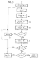
- figure 3 : un organigramme des opérations à mettre en oeuvre dans une variante préférée du procédé de l'invention ;
- figure 4 : schéma d'un circuit préféré de charge à courant constant de la batterie.
- FIG. 1a: the characteristic charge curve of a cadmium-nickel type battery already mentioned previously;
- FIG. 1b: the appearance of a signal for variation of the battery voltage (and no longer of the voltage of the battery itself) after digital connection;
- FIG. 1c: the result of a filtering treatment applied to the digital measurement of the variation of the voltage, in order to extract therefrom a signal which can be used preferentially;
- FIG. 1d: the characteristic curve of evolution of the temperature of the battery during charging;
- Figure 2: the schematic representation of an integrated circuit usable to implement the method of the invention;
- FIG. 3: a flowchart of the operations to be implemented in a preferred variant of the method of the invention;
- Figure 4: diagram of a preferred constant current charging circuit of the battery.
La figure 2 montre un circuit intégré 1 utilisable pour mettre en oeuvre le procédé de l'invention afin de charger une batterie 2 à partir d'une source de courant 3. La source de courant 3 est représentée ici d'une manière schématique avec un transformateur 4, un pont redresseur 5 et un filtre 6. La figure 4 montrera une variante préférée de réalisation d'un circuit débitant un courant de charge fort et constant. La batterie 2 est reliée par des connexions 7 et 8 au circuit de charge 3.FIG. 2 shows an
Dans l'invention, on mesure avec un convertisseur analogique numérique 9, périodiquement, la tension de charge de la batterie pendant sa charge. Cette tension est prélevée par exemple par branchement du convertisseur analogique numérique 9 aux connexions 7 et 8. Le convertisseur analogique numérique 9 produit un signal de mesure en mode binaire disponible sur ses sorties 10 à 11. Les sorties 10 à 11 du convertisseur analogique numérique 9 sont reliées par un bus 12 du circuit intégré à un micro-processeur 13 qui gère les mesures et qui produit un signal d'arrêt de la charge quand la charge est nominale.In the invention, the charging voltage of the battery is measured periodically with an analog to
Ce signal d'arrêt de la charge est par exemple un niveau logique disponible sur une connexion 14 en sortie du micro-processeur 13 et aboutissant sur un transistor de passage 15 interposé dans l'une des connexions 7 ou 8. On peut adopter d'autres circuits d'arrêt de la charge : celui représenté n'étant montré qu'à titre indicatif. Notamment, le redresseur 5 peut être un redresseur piloté par le micro-processeur 13, auquel cas ce redresseur 5 peut, le moment venu, être invalidé.This signal for stopping the charge is for example a logic level available on a
Le micro-processeur 13 est en relation avec une mémoire programme 16 du type non-volatile (ROM). Cette mémoire 16 contient les instructions correspondants à l'exécution des étapes du procédé. Au moment de la mise sous-tension de l'ensemble, le micro-processeur 13 peut transférer les instructions contenues dans la mémoire 16 dans une mémoire de travail 17 de type à accès aléatoire également reliée au micro-processeur 13. Selon le type de micro-processeur utilisé, il pourra aussi lui être possible d'exécuter les instructions lues directement dans la mémoire non-volatile 16. La mémoire à accès aléatoire volatile 17 comporte, par ailleurs, un jeu de registres utilisables pour stocker les valeurs de variables de travail élaborées dans les différentes phases du procédé.The
Le micro-processeur 13 peut enfin être relié à un circuit d'alarme 18 comportant par exemple une lampe ou un haut-parleur. Le micro-processeur 13 reçoit un signal d'horloge H et émet, par ailleurs, sur un bus de commande 19 des ordres à destination des mémoires 16 et 17 et du convertisseur analogique numérique 9. Notamment, le cadencement de l'échantillonnage effectué par le convertisseur analogique numérique 9 est provoqué par le micro-processeur 13. Dans un exemple, ce cadencement est de l'ordre de une mesure par seconde.The
Sur la figure 3, on reconnaît les principales étapes d'une mise en oeuvre préférée du procédé de l'invention. Le procédé commence par une initialisation des variables d'état du système. Notamment, on met à zéro un indice n repérant le rang temporel de chacun des échantillons, ainsi que deux variables z et w, dont on expliquera la signification par la suite. L'initialisation n'est pas nécessairement une initialisation à une valeur nulle. La notion de rang n'est par ailleurs pas indispensable. Elle n'est utile que si on veut, dans la mémoire de travail 17, limiter le nombre de registre d'état dont on veut se servir. Le cadencement du convertisseur analogique numérique 9, ainsi que la suite de toutes les opérations montrées sur la figure 3 correspond à chaque fois à une valeur donnée du rang. Les traitements sont menés à terme dans la durée, à peu près une seconde, qui sépare chacune des mesures.In Figure 3, we recognize the main steps of a preferred implementation of the method of the invention. The process begins with an initialization of the system state variables. In particular, we set to zero an index n identifying the temporal rank of each of the samples, as well as two variables z and w, the meaning of which will be explained below. Initialization is not necessarily initialization to a zero value. The notion of rank is also not essential. It is only useful if you want, in working
Dans un premier temps, le convertisseur analogique numérique 9 échantillonne la mesure de la tension V à l'étape 20.1 et produit un premier signal numérisé de mesure Yn. Dans une étape 20.2 consécutive à l'étape 20.1 on calcule à partir de Yn une dérivée ou pseudo dérivée dn = Yn - Yn-k. Le signal dn, dit deuxième signal, est montré sur la Figure 1b. Le signal dn, qui représente la variation de la tension de batterie, subit des marches d'escaliers qui sont dues à la quantification du convertisseur analogique numérique 9. Ce signal n'est pas facilement exploitable compte-tenu de son caractère erratique. Cependant, on pourrait imaginer de l'exploiter tel que pour repérer son maximum correspondant au point d'inflexion I de la Figure 1a. Il suffirait de repérer l'instant où ce signal dn deviendrait supérieur à un seuil prédéterminé.Firstly, the analog-to-
La constante k est par exemple fixée à 10. Le deuxième signal ainsi élaboré, dn, est représentatif de la variation de la tension de charge au cours d'une période. La durée de cette période est de k échantillons. Ce n'est pas exactement une dérivée, mais une approximation simple qui a l'avantage par ailleurs d'être calculée facilement par le micro-processeur 13 compte-tenu de ce qu'il n'y a qu'une soustraction à faire. Une division par k est omise puisque k est constant d'un bout à l'autre du procédé. La valeur k peut être choisie en fonction du type de batteries à charger.The constant k is for example fixed at 10. The second signal thus produced, d n , is representative of the variation of the charging voltage during a period. The duration of this period is k samples. It is not exactly a derivative, but a simple approximation which has the advantage of being easily calculated by the
Dans le but de calculer dn, on stockera d'une manière permanente dans la mémoire 17, les k derniers échantillons mesurés Yn à Yn-k. Au moment où un nouvel échantillon est mesuré, il vient prendre la place du dernier échantillon Yn mesuré, celui-ci prend la place de l'échantillon Yn-1, et ainsi de suite, l'ancien échantillon Yn-k disparaissant. Ceci est représenté schématiquement sur la Figure 2 par des flèches de décalage du contenu des registres de la mémoire 17. En pratique, ceci peut-être effectué différemment en modifiant tout simplement les adresses des registres utiles.In order to calculate d n , the last k measured samples Y n to Y nk will be permanently stored in
Le signal dn est bruité du fait de la quantification dans le convertisseur analogique numérique 9. Les problèmes de quantification sont résolus en lissant la dérivée pour obtenir une dérivée lissée plus facilement exploitable. Ce lissage correspond à un amortissement appliqué sur le signal quantifié dn de façon à produire un troisième signal zn montré sur la Figure 1c. Le signal zn est obtenu au cours d'une étape 20.3 consécutive à l'étape 20.2 et dans laquelle on effectue le calcul suivant : zn = 0,99 zn-1 + 0,01 dn. Cette méthode donne un lissage par calcul de la moyenne de la dérivée dn.The signal dn is noisy due to the quantization in the analog-to-
Comme on désire détecter le point d'inflexion I de la courbe de la Figure 1a, on va repérer le sommet, la valeur extrême, de la valeur zn, Figure 1c. Ceci est effectué au cours d'un test 21 au cours duquel on compare en permanence zn que l'on vient de calculer au zn précédent et stocké dans un registre.As we wish to detect the inflection point I of the curve of Figure 1a, we will locate the vertex, the extreme value, of the value z n , Figure 1c. This is done during a
Tant que la nouvelle valeur calculée pour zn est supérieure à la valeur zn-1 précédente on n'a pas atteint le maximum. Dans ce cas, on remplace dans le registre zmax de la mémoire 17, la valeur zn-1 mémorisée par la nouvelle valeur Zn calculée. Par contre, lorsqu'on a passé le sommet, le résultat du test 21 devient négatif et dans ce cas on arrête la charge en émettant sur la connexion 14 l'ordre logique adéquat. On remarque en pratique que l'instant où on détecte le maximum est légèrement retardé par rapport au moment où le point d'inflexion de la tension est apparu. Ceci est dû au lissage de la dérivée. En pratique, le calcul que l'on a indiqué provoque un retard d'un centaine d'échantillons. On peut, en modifiant le calcul de l'étape 20.3, et/ou la fréquence de scrutation par le convertisseur analogique 9, modifier ce retard à la détection. Il semble cependant que la durée de cent secondes soit un compromis acceptable et qui permet en tout cas à un déclenchement en arrêt avant le point B.As long as the new value calculated for z n is greater than the previous value z n-1, the maximum has not been reached. In this case, in the register z max of the
Le déclenchement ainsi décrit de l'arrêt de la charge est automatique lorsqu'on est dans la partie significative droite de la courbe de la tension V. Un problème peut survenir qui consiste à distinguer le sommet de la dérivée lissée Zn, correspondant au point C, d'une part d'un sommet 22 situé au tout début de la courbe et d'autre part de nombreux autres maximum locaux 25 situés dans la partie médiane de la courbe. Le sommet 22 situé au début de la courbe est créé par les conditions d'initialisation des variables à zéro au début de la charge et par une diminution de la pente de la tension de batterie en début de charge. En effet, lors des premières secondes de connexion, la tension aux bornes de la batterie monte très rapidement : montée 23 Figure 1a. Puis elle redescend provoquant au passage le sommet 22 de la dérivée. Les maximums locaux 25 sont eux consécutifs à la quantification du convertisseur analogique numérique 9 dans une zone ou la pente de la courbe de la tension de charge est constante, zone 24 sur la Figure 1a.The triggering thus described of the stop of the charge is automatic when one is in the significant right part of the curve of the voltage V. A problem can arise which consists in distinguishing the top of the smoothed derivative Z n , corresponding to the point C, on the one hand a
Pour éliminer ces problèmes, et rendre le système complètement automatique au lieu que seulement sa fin ne le soit, on effectue deux opérations. D'une part, au cours d'un test 26, effectué après l'étape 20.3, on s'assure que la durée depuis le début de la charge est supérieure à une durée de base T. Par exemple, la durée T de base sera égale à cent secondes : égale à cent fois la durée qui sépare deux échantillons successifs. Tant que cette durée n'est pas atteinte, on calcule une variable Wn correspondant à un quatrième signal selon un mode exprimé dans l'étape 27 : wn = zn. Ceci permet d'éviter des phénomènes transitoires qui se produisent au début de la charge.To eliminate these problems, and to make the system completely automatic instead of just ending it, we perform two operations. On the one hand, during a
Puis, après ce début de la charge, le calcul de la variable wn est entrepris comme indiqué à l'étape 28, en faisant en sorte que wn soit égal à![]()
![]()
Le calcul n'est en pratique effectué que si wn est inférieur à zn. Si ce n'est pas le cas on remplace, pour le rang d'opérations considéré, wn par zn.The calculation is only carried out in practice if w n is less than z n . If this is not the case, we replace, for the rank of operations considered, w n by z n .
Ceci revient à filtrer sur environ un milliers d'échantillons la valeur de la dérivée (tout en ne gardant en mémoire que k échantillons). Le fait d'appliquer préalablement l'étape 27 permet de fixer d'une manière arbitraire la dérivée très amortie wn rapidement, à une valeur significative sans avoir besoin d'attendre qu'elle y monte. On repère ensuite que l'on est dans une partie significative d'évolution de la tension V en effectuant au cours d'un test 29 la comparaison de la dérivée lissée zn, troisième signal, à la dérivée très amortie wn, quatrième signal. Cette comparaison est entreprise sous la forme d'un rapport. Tant que la dérivée ne dépasse pas la dérivée moyenne à long terme de plus de cinquante pour cent on considérera que le test 29 est négatif et on laissera la charge se poursuivre. On a retenu cinquante pour cent mais évidemment on pourrait retenir un autre rapport, par exemple vingt cinq pour cent ou même éventuellement soixante dix ou quatre vingt pour cent. Au besoin on pourrait utiliser ce test, pour arrêter la charge.This amounts to filtering the value of the derivative over approximately one thousand samples (while keeping only k samples in memory). The fact of applying
Dès que le résultat du test 29 devient positif, on est dans la phase significative de mesure et on peut, en effectuant le test 21, repérer la valeur maximum zn. On considère en effet lorsque le test 29 est positif que la tension de batterie est entrée dans une phase d'augmentation rapide de sa pente. Ceci ne se produit que dans cette zone de la courbe de charge, quel que soit le type de la batterie. Ceci permet d'isoler la période, située à droite d'une durée XX à partir de laquelle la dérivée lissée zn ne présente plus de maxima locaux ou autres singularités. Il est donc facile à partir de ce point de détecter le sommet de cette dérivée lissée.As soon as the result of
Dans l'invention pour que l'organigramme de la Figure 3 fonctionne au mieux, il est préférable d'avoir une source de courant qui ne varie pas avec la tension débitée, ou avec le temps, ou la température du circuit d'alimentation. La figure 4 montre un exemple préféré de réalisation d'une telle source de courant stable dans le temps et indépendante de la variation de la tension d'alimentation. Une alimentation stabilisée en tension non représenté alimente sous 12 volts, le circuit intégré 1 ainsi qu'un circuit 30, de type LM 317 de SGS THIOMSON MICROELECTRONICS. Ce circuit 30 comporte deux sorties 31 et 32, dites Vout et Adjust, entre lesquelles on peut mettre en parallèle une résistance de réglage 33. La résistance 33 permet d'imposer à la batterie 2 une tension disponible à la sortie 32 et un courant égal au rapport de la différence de tension entre les sorties 31 et 32 par la valeur de la résistance 33. Le circuit LM 317 impose une tension Vout-Vadjust égale à une référence de 1,27 Volts. Donc le courant constant vaut I=1,27/résistance 33.In the invention for the flowchart of Figure 3 to work best, it is preferable to have a current source which does not vary with the voltage supplied, or with time, or the temperature of the supply circuit. Figure 4 shows a preferred embodiment of such a current source stable over time and independent of the variation of the supply voltage. A voltage stabilized supply, not shown, supplies the
Claims (9)
caractérisé en ce que pour déterminer que la tension mesurée pendant une période commence à croître moins vite que pendant une période précédente,
characterized in that in order to determine that the voltage measured during a period begins to grow less quickly than in a previous period,
- on attend un certain nombre de périodes (T) avant d'autoriser cette détermination. 3 - Method according to one of claims 1 to 2, characterized in that to determine that the voltage measured during a period increases less quickly than during a previous period,
- we wait for a certain number of periods (T) before authorizing this determination.
- on charge la batterie à courant rigoureusement constant. 4 - Method according to one of claims 1 to 3, characterized in that
- the battery is charged at a strictly constant current.
- on mesure périodiquement (H) la tension de charge de la batterie. 5 - Method according to one of claims 1 to 4, characterized in that
- the battery charge voltage is periodically measured (H).
- on détermine que la charge est nominale à un moment retardé (C) par rapport au moment repéré (I). 6 - Method according to one of claims 1 to 5, characterized in that
- it is determined that the load is nominal at a delayed time (C) relative to the identified time (I).
Applications Claiming Priority (2)
| Application Number | Priority Date | Filing Date | Title |
|---|---|---|---|
| FR9303153 | 1993-03-18 | ||
| FR9303153A FR2702884B1 (en) | 1993-03-18 | 1993-03-18 | Method for rapid charging of a battery and integrated circuit for implementing this method. |
Publications (2)
| Publication Number | Publication Date |
|---|---|
| EP0616411A1 true EP0616411A1 (en) | 1994-09-21 |
| EP0616411B1 EP0616411B1 (en) | 1996-03-13 |
Family
ID=9445123
Family Applications (1)
| Application Number | Title | Priority Date | Filing Date |
|---|---|---|---|
| EP94400575A Expired - Lifetime EP0616411B1 (en) | 1993-03-18 | 1994-03-16 | Quick charge method for battery and integrated circuit for performing the method |
Country Status (5)
| Country | Link |
|---|---|
| US (1) | US5612607A (en) |
| EP (1) | EP0616411B1 (en) |
| JP (1) | JPH06351169A (en) |
| DE (1) | DE69400088T2 (en) |
| FR (1) | FR2702884B1 (en) |
Cited By (3)
| Publication number | Priority date | Publication date | Assignee | Title |
|---|---|---|---|---|
| GB2292828A (en) * | 1994-08-29 | 1996-03-06 | Andrew Corp | Charging rechargeable batteries for portable cellular telephones utilising battery output voltage to initiate and end fast charging |
| WO2007004098A1 (en) * | 2005-06-30 | 2007-01-11 | Koninklijke Philips Electronics N.V. | Method and charger for boost charging a chargeable battery on the basis of a physical model |
| CN100392942C (en) * | 2005-10-31 | 2008-06-04 | 中兴通讯股份有限公司 | Device and method for controlling procedure of charging batteries |
Families Citing this family (10)
| Publication number | Priority date | Publication date | Assignee | Title |
|---|---|---|---|---|
| KR100265709B1 (en) * | 1996-10-15 | 2000-09-15 | 윤종용 | A secondary charginf apparatus |
| US5770938A (en) * | 1996-12-09 | 1998-06-23 | Industrial Technology Research Institute | Real time charging control of a fast battery charger |
| EP1025606A1 (en) | 1998-08-13 | 2000-08-09 | Milwaukee Electric Tool Corporation | Battery charger |
| US7336054B2 (en) * | 1998-08-14 | 2008-02-26 | Milwaukee Electric Tool Corporation | Apparatus and method of activating a microcontroller |
| JP2002044879A (en) * | 2000-07-21 | 2002-02-08 | Honda Motor Co Ltd | Charging method and apparatus of secondary battery |
| US20060113956A1 (en) * | 2003-05-07 | 2006-06-01 | Bublitz Scott D | Battery charger and assembly |
| RU2474027C2 (en) * | 2006-11-27 | 2013-01-27 | ЮНИВЕРСАЛ СУПЕРКАПАСИТОРЗ ЭлЭлСи | Method to charge electrochemical capacitors with double electric layer |
| DE102007051052A1 (en) * | 2007-10-16 | 2009-04-23 | C. & E. Fein Gmbh | Method for charging rechargeable lithium batteries, charger and rechargeable lithium battery |
| US9229502B2 (en) * | 2012-04-05 | 2016-01-05 | Apple Inc. | Fast wake-up of differential receivers using common mode decoupling capacitors |
| US10164450B2 (en) * | 2015-08-17 | 2018-12-25 | Ford Global Technologies, Llc | Early alert of battery thermal state based on voltage |
Citations (4)
| Publication number | Priority date | Publication date | Assignee | Title |
|---|---|---|---|---|
| EP0005841A2 (en) * | 1978-05-31 | 1979-12-12 | Black & Decker Inc. | Method of charging batteries and apparatus therefor |
| US4503378A (en) * | 1983-05-02 | 1985-03-05 | General Motors Corporation | Charging system for nickel-zinc batteries |
| EP0444617A2 (en) * | 1990-02-28 | 1991-09-04 | Hitachi Maxell Ltd. | Method of charging secondary batteries |
| EP0493226A1 (en) * | 1990-12-21 | 1992-07-01 | Societe Generale De Travaux Electriques | Method and device for charging an accumulator |
Family Cites Families (1)
| Publication number | Priority date | Publication date | Assignee | Title |
|---|---|---|---|---|
| US4746852A (en) * | 1984-10-29 | 1988-05-24 | Christie Electric Corp. | Controller for battery charger |
-
1993
- 1993-03-18 FR FR9303153A patent/FR2702884B1/en not_active Expired - Fee Related
-
1994
- 1994-03-16 EP EP94400575A patent/EP0616411B1/en not_active Expired - Lifetime
- 1994-03-16 DE DE69400088T patent/DE69400088T2/en not_active Expired - Fee Related
- 1994-03-18 US US08/210,701 patent/US5612607A/en not_active Expired - Fee Related
- 1994-03-18 JP JP6073886A patent/JPH06351169A/en not_active Withdrawn
Patent Citations (4)
| Publication number | Priority date | Publication date | Assignee | Title |
|---|---|---|---|---|
| EP0005841A2 (en) * | 1978-05-31 | 1979-12-12 | Black & Decker Inc. | Method of charging batteries and apparatus therefor |
| US4503378A (en) * | 1983-05-02 | 1985-03-05 | General Motors Corporation | Charging system for nickel-zinc batteries |
| EP0444617A2 (en) * | 1990-02-28 | 1991-09-04 | Hitachi Maxell Ltd. | Method of charging secondary batteries |
| EP0493226A1 (en) * | 1990-12-21 | 1992-07-01 | Societe Generale De Travaux Electriques | Method and device for charging an accumulator |
Cited By (5)
| Publication number | Priority date | Publication date | Assignee | Title |
|---|---|---|---|---|
| GB2292828A (en) * | 1994-08-29 | 1996-03-06 | Andrew Corp | Charging rechargeable batteries for portable cellular telephones utilising battery output voltage to initiate and end fast charging |
| US5640079A (en) * | 1994-08-29 | 1997-06-17 | Andrew Corporation | Battery charger for portable rechargeable batteries |
| GB2292828B (en) * | 1994-08-29 | 1997-11-05 | Andrew Corp | Method and system for charging portable rechargeable batteries |
| WO2007004098A1 (en) * | 2005-06-30 | 2007-01-11 | Koninklijke Philips Electronics N.V. | Method and charger for boost charging a chargeable battery on the basis of a physical model |
| CN100392942C (en) * | 2005-10-31 | 2008-06-04 | 中兴通讯股份有限公司 | Device and method for controlling procedure of charging batteries |
Also Published As
| Publication number | Publication date |
|---|---|
| FR2702884A1 (en) | 1994-09-23 |
| FR2702884B1 (en) | 1995-04-28 |
| JPH06351169A (en) | 1994-12-22 |
| EP0616411B1 (en) | 1996-03-13 |
| DE69400088D1 (en) | 1996-04-18 |
| DE69400088T2 (en) | 1996-08-22 |
| US5612607A (en) | 1997-03-18 |
Similar Documents
| Publication | Publication Date | Title |
|---|---|---|
| EP0616411B1 (en) | Quick charge method for battery and integrated circuit for performing the method | |
| CA2546891C (en) | Equilibrated charging method for a lithium-ion or lithium-polymer battery | |
| FR2897945A1 (en) | Rechargeable battery e.g. lithium ion battery, internal charge state indicating quantity calculating device for vehicle, has correction unit to correct battery resistance value using voltage difference, where corrected value indicates state | |
| CA2594826C (en) | Method for the balanced charging of a lithium-ion or lithium-polymer battery | |
| FR2841385A1 (en) | DEVICE FOR CALCULATING THE DETERIORATION DEGREE AND METHOD FOR CALCULATING THE DETERIORATION DEGREE OF A BATTERY | |
| FR2884928A1 (en) | Neural network device for detecting e.g. state of charge of lead storage battery, has neural network controller providing, by applying neutral network calculation on input parameters, output signal indicating internal state of battery | |
| EP2105755A1 (en) | Method for estimating the state of charge of a vehicular battery | |
| EP0498715B1 (en) | Process for optimizing the charge of an accumulator battery and apparatus for carrying out the process | |
| FR2605415A1 (en) | APPARATUS FOR MONITORING THE CHARGE STATE OF A BATTERY | |
| FR2547468A1 (en) | BATTERY CHARGING APPARATUS | |
| EP3371544B1 (en) | Method of firing an electronic detonator and electronic detonator | |
| EP0802464B1 (en) | Method to regulate the exciting current of a automotive vehicle generator using digital processing and regulator device for carrying out this method | |
| FR2977678A1 (en) | Method for diagnosing battery, involves charging battery to reach predetermined maximum voltage for specific time in phase, and calculating state of health of battery from measured time and charging time | |
| FR2486243A1 (en) | METHOD AND APPARATUS FOR DETECTING THE PRESENCE OF A SUBSTANCE ON THE SURFACE OF A LIQUID | |
| EP3729118B1 (en) | Method for determining a sequence of discharge currents applicable to a lithium-ion cell at a given temperature | |
| FR2826125A1 (en) | Method for finding state of charge of mobile telephone battery, comprises integration of battery resistance current and positive and negative reference currents and comparison with reference voltage | |
| WO1981002066A1 (en) | Method for measuring the charge state of an accumulator and device for implementing such method | |
| EP3104143A1 (en) | System comprising a photovoltaic cell and a device for measuring light intensity, and method for measuring a light intensity received by said photovoltaic cell | |
| EP0240402B1 (en) | Method and device for sending an electrical current to a circuit with the aid of a transistor | |
| EP0596789A1 (en) | Method and device for measuring the charge of an accumulator battery | |
| FR2670953A1 (en) | METHOD AND DEVICE FOR CHARGING A BATTERY. | |
| FR2766991A1 (en) | Regulation of vehicle alternator by digital control | |
| FR2672704A1 (en) | FLASH TRANSMISSION DEVICE. | |
| EP3650875B1 (en) | Method for testing an electrical protection unit and protection unit implementing such a method | |
| FR2750768A1 (en) | Determination of residual capacity of nickel cadmium batteries |
Legal Events
| Date | Code | Title | Description |
|---|---|---|---|
| PUAI | Public reference made under article 153(3) epc to a published international application that has entered the european phase |
Free format text: ORIGINAL CODE: 0009012 |
|
| 17P | Request for examination filed |
Effective date: 19940527 |
|
| AK | Designated contracting states |
Kind code of ref document: A1 Designated state(s): DE FR GB IT |
|
| 17Q | First examination report despatched |
Effective date: 19941215 |
|
| GRAA | (expected) grant |
Free format text: ORIGINAL CODE: 0009210 |
|
| AK | Designated contracting states |
Kind code of ref document: B1 Designated state(s): DE FR GB IT |
|
| REF | Corresponds to: |
Ref document number: 69400088 Country of ref document: DE Date of ref document: 19960418 |
|
| GBT | Gb: translation of ep patent filed (gb section 77(6)(a)/1977) |
Effective date: 19960401 |
|
| ITF | It: translation for a ep patent filed |
Owner name: PORTA CHECCACCI E BOTTI S.R.L. |
|
| PLBE | No opposition filed within time limit |
Free format text: ORIGINAL CODE: 0009261 |
|
| STAA | Information on the status of an ep patent application or granted ep patent |
Free format text: STATUS: NO OPPOSITION FILED WITHIN TIME LIMIT |
|
| 26N | No opposition filed | ||
| REG | Reference to a national code |
Ref country code: GB Ref legal event code: IF02 |
|
| PGFP | Annual fee paid to national office [announced via postgrant information from national office to epo] |
Ref country code: DE Payment date: 20030327 Year of fee payment: 10 |
|
| PG25 | Lapsed in a contracting state [announced via postgrant information from national office to epo] |
Ref country code: DE Free format text: LAPSE BECAUSE OF NON-PAYMENT OF DUE FEES Effective date: 20041001 |
|
| PGFP | Annual fee paid to national office [announced via postgrant information from national office to epo] |
Ref country code: FR Payment date: 20050308 Year of fee payment: 12 |
|
| PG25 | Lapsed in a contracting state [announced via postgrant information from national office to epo] |
Ref country code: IT Free format text: LAPSE BECAUSE OF NON-PAYMENT OF DUE FEES;WARNING: LAPSES OF ITALIAN PATENTS WITH EFFECTIVE DATE BEFORE 2007 MAY HAVE OCCURRED AT ANY TIME BEFORE 2007. THE CORRECT EFFECTIVE DATE MAY BE DIFFERENT FROM THE ONE RECORDED. Effective date: 20050316 |
|
| PGFP | Annual fee paid to national office [announced via postgrant information from national office to epo] |
Ref country code: GB Payment date: 20050316 Year of fee payment: 12 |
|
| PG25 | Lapsed in a contracting state [announced via postgrant information from national office to epo] |
Ref country code: GB Free format text: LAPSE BECAUSE OF NON-PAYMENT OF DUE FEES Effective date: 20060316 |
|
| GBPC | Gb: european patent ceased through non-payment of renewal fee |
Effective date: 20060316 |
|
| REG | Reference to a national code |
Ref country code: FR Ref legal event code: ST Effective date: 20061130 |
|
| PG25 | Lapsed in a contracting state [announced via postgrant information from national office to epo] |
Ref country code: FR Free format text: LAPSE BECAUSE OF NON-PAYMENT OF DUE FEES Effective date: 20060331 |