EP0417431A1 - Verfahren zur Überwachung einer Bremseinrichtung auf Überlast - Google Patents
Verfahren zur Überwachung einer Bremseinrichtung auf Überlast Download PDFInfo
- Publication number
- EP0417431A1 EP0417431A1 EP90113905A EP90113905A EP0417431A1 EP 0417431 A1 EP0417431 A1 EP 0417431A1 EP 90113905 A EP90113905 A EP 90113905A EP 90113905 A EP90113905 A EP 90113905A EP 0417431 A1 EP0417431 A1 EP 0417431A1
- Authority
- EP
- European Patent Office
- Prior art keywords
- brake
- deformation
- pressure
- value
- brake drum
- Prior art date
- Legal status (The legal status is an assumption and is not a legal conclusion. Google has not performed a legal analysis and makes no representation as to the accuracy of the status listed.)
- Granted
Links
Images
Classifications
-
- F—MECHANICAL ENGINEERING; LIGHTING; HEATING; WEAPONS; BLASTING
- F16—ENGINEERING ELEMENTS AND UNITS; GENERAL MEASURES FOR PRODUCING AND MAINTAINING EFFECTIVE FUNCTIONING OF MACHINES OR INSTALLATIONS; THERMAL INSULATION IN GENERAL
- F16D—COUPLINGS FOR TRANSMITTING ROTATION; CLUTCHES; BRAKES
- F16D66/00—Arrangements for monitoring working conditions, e.g. wear, temperature
-
- B—PERFORMING OPERATIONS; TRANSPORTING
- B60—VEHICLES IN GENERAL
- B60T—VEHICLE BRAKE CONTROL SYSTEMS OR PARTS THEREOF; BRAKE CONTROL SYSTEMS OR PARTS THEREOF, IN GENERAL; ARRANGEMENT OF BRAKING ELEMENTS ON VEHICLES IN GENERAL; PORTABLE DEVICES FOR PREVENTING UNWANTED MOVEMENT OF VEHICLES; VEHICLE MODIFICATIONS TO FACILITATE COOLING OF BRAKES
- B60T17/00—Component parts, details, or accessories of power brake systems not covered by groups B60T8/00, B60T13/00 or B60T15/00, or presenting other characteristic features
- B60T17/18—Safety devices; Monitoring
- B60T17/22—Devices for monitoring or checking brake systems; Signal devices
-
- F—MECHANICAL ENGINEERING; LIGHTING; HEATING; WEAPONS; BLASTING
- F16—ENGINEERING ELEMENTS AND UNITS; GENERAL MEASURES FOR PRODUCING AND MAINTAINING EFFECTIVE FUNCTIONING OF MACHINES OR INSTALLATIONS; THERMAL INSULATION IN GENERAL
- F16D—COUPLINGS FOR TRANSMITTING ROTATION; CLUTCHES; BRAKES
- F16D66/00—Arrangements for monitoring working conditions, e.g. wear, temperature
- F16D2066/001—Temperature
-
- F—MECHANICAL ENGINEERING; LIGHTING; HEATING; WEAPONS; BLASTING
- F16—ENGINEERING ELEMENTS AND UNITS; GENERAL MEASURES FOR PRODUCING AND MAINTAINING EFFECTIVE FUNCTIONING OF MACHINES OR INSTALLATIONS; THERMAL INSULATION IN GENERAL
- F16D—COUPLINGS FOR TRANSMITTING ROTATION; CLUTCHES; BRAKES
- F16D66/00—Arrangements for monitoring working conditions, e.g. wear, temperature
- F16D2066/006—Arrangements for monitoring working conditions, e.g. wear, temperature without direct measurement of the quantity monitored, e.g. wear or temperature calculated form force and duration of braking
-
- F—MECHANICAL ENGINEERING; LIGHTING; HEATING; WEAPONS; BLASTING
- F16—ENGINEERING ELEMENTS AND UNITS; GENERAL MEASURES FOR PRODUCING AND MAINTAINING EFFECTIVE FUNCTIONING OF MACHINES OR INSTALLATIONS; THERMAL INSULATION IN GENERAL
- F16D—COUPLINGS FOR TRANSMITTING ROTATION; CLUTCHES; BRAKES
- F16D2125/00—Components of actuators
- F16D2125/18—Mechanical mechanisms
- F16D2125/20—Mechanical mechanisms converting rotation to linear movement or vice versa
- F16D2125/22—Mechanical mechanisms converting rotation to linear movement or vice versa acting transversely to the axis of rotation
- F16D2125/28—Cams; Levers with cams
- F16D2125/30—Cams; Levers with cams acting on two or more cam followers, e.g. S-cams
Definitions
- the invention relates to a method for monitoring a wear-adjusting device which can be actuated by pressure and, when a brake is applied after a selected component has been heated to a permissible temperature, reaches its load limit for overload according to the preamble of patent claim 1 and an arrangement for carrying out the method.
- Such a method is known from international patent application WO 84/00406.
- This method provides for the monitoring of a braking device of the present generic type for overload by measuring the temperature of the selected component and emitting a warning signal when it reaches the permissible value.
- this method uses temperature sensors on or in the vicinity of the selected component, as a brake drum or a brake disc.
- the disadvantage of this method is the inertia of the temperature monitoring.
- the selected component may already have exceeded the permissible temperature, so the braking device may already be overloaded before the warning signal is given due to the inertia mentioned.
- the present invention is therefore based on the object of improving a method of the type mentioned at the beginning with simple means such that the monitoring of the braking device for overload takes place largely without delay.
- This object is achieved by the invention specified in claim 1.
- Advantageous further developments and arrangements for carrying out the invention are specified in the subclaims.
- the invention uses, among other things, the knowledge that there is a connection between the pressure supplied to the braking device, the resulting deformation of a selected component and its temperature.
- the invention can be carried out with components that do not have to be exposed to the temperatures occurring in the braking device.
- the invention can therefore be carried out with a particularly low susceptibility to faults.
- the invention requires particularly little special effort if one or more of the components required for its implementation are already available for other reasons, e.g. a pressure sensor for a certain type of electrical brake pressure control and / or a rotation angle (stroke) sensor that can be used as a deformation sensor for monitoring the wear adjustment device.
- a pressure sensor for a certain type of electrical brake pressure control and / or a rotation angle (stroke) sensor that can be used as a deformation sensor for monitoring the wear adjustment device.
- the brake drum is preferably considered as the selected component.
- the selected components are preferably the brake caliper in the case of a partial disc brake and the brake housing taking over the function of the brake disc in the case of a full disc brake.
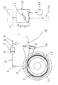
- the figure shows schematically a braking device with an arrangement for carrying out the invention.
- the braking device consists of a drum brake with a brake drum (1) and brake shoes (2, 17) and an actuating device (3, 4, 5, 7).
- the actuating device consists of a brake cylinder (7) with a piston member (6), which can be designed as a piston with an annular seal (s) or as a membrane piston, a brake cam (3) and a piston member (6) connecting the brake cam (3) Transmission device (4, 5) which contains a wear adjusting device constructed in a known manner and therefore not shown in detail.
- the brake drum diameter depends on the temperature of the brake drum (1) and any mechanical basic load resulting from the assembly.
- the temperature of the brake drum (1) depends not only on the ambient temperature but also on the temperature rise during the previous brake application (s).
- the brake drum (1) is mechanically loaded after overcoming a response resistance by the contact pressure of the brake shoes (2, 17) and correspondingly elastically deformed. At the same time, the brake drum (1) is warmed up by the braking work performed and is additionally thermally deformed. The brake drum diameter changes (increases) accordingly.
- the brake drum may be deformed differently depending on its temperature and consequently the brake drum diameter may be different. At a given pressure, there is therefore a relationship between the brake drum diameter and the temperature of the brake drum (1).
- the temperature of the brake drum (1) indicates the load condition of the brake device. If the temperature of the brake drum reaches a permissible value, hereinafter permissible temperature (T), the functionality of the brake device is at risk as a result of "fadings" and its load limit is reached.
- T permissible temperature
- the brake drum (1) is selected as the component which is decisive for monitoring the braking device for overload.
- the deformation of the brake drum (1) in the form of the change in its diameter results in a change in the travel of components of the actuating device which are involved in the brake actuation.
- the piston member (6) and with it the transmission device (4, 5) as well as the brake cam (3) and the brake shoes (2, 17) are in a retracted position under the action of return means (not shown).
- Any beam (16) through the axis of rotation of the brake cam (3) defines the assigned angle of rotation zero (0) of the brake cam (3).
- the brake shoes (2, 17) have an air gap with respect to the brake drum (1).
- the wear adjustment device compensates for an increase in the clearance due to brake pad wear, this depends, apart from the basic setting, only on the temperature-dependent deformation of the brake drum (1).
- the air gap is overcome against the response resistance - this includes, among other things, the force of the resetting means - by rotating the brake cam (3) by an initial angle of rotation (h isto ) and thereby the brake shoes (2, 17) straight to the brake drum (1) created.
- the initial angle of rotation (h isto ) therefore represents the existing clearance.
- the pressure assigned to the initial angle of rotation (h isto ) is the response pressure (P isto ).
- the arrangement for carrying out a method for monitoring the braking device for overload which is also shown schematically in the figure, is to be designated with (8, 12, 15) in the basic version and consists in this basic version of a deformation sensor (15), a pressure sensor (8) and an evaluation electronics (12).
- the deformation sensor (15) detects the rotational angle (h) of the brake cam (3) and converts it into an electrical deformation signal.
- the pressure sensor (8) detects the pressure (P ist ) in the brake cylinder (7) and converts it into an electrical pressure signal.
- the pressure-dependent characteristic of the rotation angle (h) of the brake drum (1) heated to the permissible temperature (T), hereinafter referred to as the deformation characteristic (11) h f (p, T ), is stored .
- the deformation characteristic (11) defines two areas in the h / p coordinate field. In the area below the deformation characteristic (11), the temperature of the brake drum (1) is below the permissible temperature (T), in the area above the deformation characteristic (11) the temperature of the brake drum (1) is above the permissible Temperature (T). The brake drum (1) has the permissible temperature (T) on the deformation characteristic (11).
- the deformation characteristic curve (11) is determined and the required heating of the brake drum (1) is carried out under the installation and operating conditions of the braking device. However, it is also possible to carry out these steps in the test field.
- the evaluation electronics (12) are connected on the input side to the outputs of the deformation sensor (15) and the pressure sensor (8).
- the evaluation electronics (12) are designed in such a way that they match the respectively detected angle of rotation (h ist ) with the value assigned to the existing pressure (P ist ) compares the deformation characteristic (11) and emits a warning signal if the value (h is ) is equal to or greater than the value of the deformation characteristic (11).
- this design of the evaluation electronics (12) makes the effect described that it emits a warning signal when the (h) by the angle of rotation and the pressure (Pist) certain point of h / p-coordinate field, the deformation characteristic (11 ) reached or exceeded in the direction of higher values of the angle of rotation (h). Since the deformation characteristic (11) corresponds to the permissible temperature (T) of the brake drum (1) and this is exceeded at higher values of (hist), the warning signal therefore indicates that the permissible temperature (T) of the brake drum (1) has been reached or exceeded. .
- (14) a device is indicated, which converts the warning signal into a form that can be detected by the driver.
- the basic version can be developed by a timer (10) indicated by a broken line in such a way that it only acts during a brake application.
- the timer (10) is designed such that it emits a measurement signal during a brake application at one or more predetermined times after the start of the brake application.
- the evaluation electronics (12) are designed in such a way that they receive the measurement signal and are activated by it, that is, they perform their function described above only after receiving a measurement signal.
- it can be provided with a holding function which ensures that the warning signal is maintained even after the measurement signal has dropped.
- the start and end of the brake application can be signaled to the timer (10) in any suitable manner, for example by a signal generator on a brake value transmitter operated by the driver.
- the timing element (10) evaluates the passage of the pressure in the brake cylinder (7) as the start and end of the brake actuation by the value of the response pressure (p, sto ).
- the timer (10) is connected to the output of the pressure sensor (8).
- the arrangement (8, 12, 15) or (8, 10, 12, 15) also allows the wear adjustment device to be checked. If this does not adjust, the deformation sensor (15) detects an unusually large initial rotation angle (h isto ) when the brake is actuated , which, by means of a suitable device or a corresponding design of the evaluation electronics (12), gives the driver an indication of a malfunction of the Wear adjustment device can be implemented.
- the evaluation electronics (12) could be designed, for example, so that when it receives a pressure signal corresponding to the response pressure ( pisto ), it carries out a plausibility check of the deformation signal, for example a comparison with a stored limit value, and emits a warning signal if a non-plausibility is found. In the advanced training with timer (10) it can be controlled by this for this plausibility check. This further training option is indicated by means of a device (14), shown in broken lines, which converts this warning signal into a form which the driver can grasp.
- the stroke of the piston member (6) could also serve as the deformation of the brake drum (1).
- the - primarily elastic - deformation of the transmission device (4, 5) would also be reflected. It is obvious that the detection of the deformation used in the exemplary embodiment by means of the angle of rotation (h) of the brake cam (3) is simpler in comparison.
- the brake drum (1) was selected as the component which is decisive for the load state of the brake device, for the reasons mentioned above.
- the technical teaching implemented in the exemplary embodiment can, however, be applied in a corresponding application to other components of a braking device with a brake drum and to completely different types of braking device.
- a brake device with a disc brake should be considered in particular.
- the stroke of a piston member could be the preferred quantity that reflects the deformation of the selected component.
Abstract
Description
- Die Erfindung betrifft ein Verfahren zur Überwachung einer eine Verschleiß-Nachstelleinrichtung aufweisenden, durch Druck betätigbaren und bei einer Bremsbetätigung nach Erwärmung eines ausgewählten Bauteils auf eine zulässige Temperatur ihre Belastungsgrenze erreichenden Bremseinrichtung auf Überlast gemäß dem Oberbegriff des Patentanspruchs 1 und eine Anordnung zur Durchführung des Verfahrens.
- Ein derartiges Verfahren ist aus der Internationalen Patentanmeldung WO 84/00406 bekannt. Dieses Verfahren sieht die Überwachung einer Bremseinrichtung der vorliegend gattungsbildenden Art auf Überlast durch Messung der Temperatur des ausgewählten Bauteils und Abgabe eines Warnsignals vor, wenn diese den zulässigen Wert erreicht. Zur Messung der Temperatur setzt dieses Verfahren Temperatursensoren an dem oder in der Nachbarschaft des ausgewählten Bauteils ein, als welches eine Bremstrommel oder eine Bremsscheibe erwähnt sind.
- Nachteilig ist bei diesem Verfahren die Trägheit der Temperaturüberwachung. Das ausgewählte Bauteil kann die zulässige Temperatur schon überschritten haben, die Bremseinrichtung kann also schon überlastet sein, bevor infolge der erwähnten Trägheit das Warnsignal abgegeben wird.
- Der vorliegenden Erfindung liegt deshalb die Aufgabe zugrunde, ein Verfahren der eingangs genannten Art mit einfachen Mitteln derart zu verbessern, daß die Überwachung der Bremseinrichtung auf Überlast weitgehend verzögerungsfrei erfolgt. Diese Aufgabe wird durch die im Patentanspruch 1 angegebene Erfindung gelöst. Vorteilhafte Weiterbildungen sowie Anordnungen zur Durchführung der Erfindung sind in den Unteransprüchen angegeben.
- Die Erfindung setzt unter anderem die Erkenntnis ein, daß zwischen dem der Bremseinrichtung zugeführten Druck, der sich dadurch einstellenden Verformung eines ausgewählten Bauteils und dessen Temperatur ein Zusammenhang besteht.
- Die Erfindung läßt sich mit Bauelementen durchführen, die den in der Bremseinrichtung auftretenden Temperaturen nicht ausgesetzt sein müssen. Die Erfindung läßt sich daher mit besonders geringer Störanfälligkeit ausführen.
- Die Erfindung bedarf besonders geringen speziellen Aufwands, wenn eines oder mehrere der zu ihrer Durchführung erforderlichen Bauelemente schon aus anderen Gründen vorhanden sind, wie z.B. ein Drucksensor bei einer bestimmten Art elektrischer Bremsdrucksteuerung und/oder ein als Verformungssensor einsetzbarer Drehwinkel- (Hub- )sensor zur Überwachung der Verschleiß-Nachstelleinrichtung.
- Enthält die Bremseinrichtung eine Trommelbremse, so kommt als ausgewähltes Bauteil bevorzugt die Bremstrommel in Betracht. Enthält die Bremseinrichtung eine Scheibenbremse, so kommen als ausgewählte Bauteile bevorzugt im Falle einer Teilscheibenbremse der Bremssattel und im Falle einer Vollscheibenbremse das die Funktion der Bremsscheibe übernehmende Bremsgehäuse in Betracht.
- Weitere Vorteile der Erfindung werden in deren nunmehr folgende Erläuterung anhand eines Ausführungsbeispiels angegeben.
- Mit strichpunktierten Linien als elektrischen Verbindungen zeigt die Figur schematisch eine Bremseinrichtung mit Anordnung zur Durchführung der Erfindung.
- Die Bremseinrichtung besteht aus einer Trommelbremse mit einer Bremstrommel (1) und Bremsbacken (2, 17) sowie einer Betätigungseinrichtung (3, 4, 5, 7). Die Betätigungseinrichtung besteht aus einem Bremszylinder (7) mit einem Kolbenglied (6), welches als Kolben mit Ringdichtung(en) oder als Membrankolben ausgebildet sein kann, einem Bremsnocken (3) und einer das Kolbenglied (6) mit dem Bremsnocken (3) verbindenden Übertragungseinrichtung (4, 5), die eine in bekannter Weise aufgebaute und deshalb nicht näher dargestellte Verschleiß-Nachstelleinrichtung enthält.
- Eine solche Bremseinrichtung ist bekannt. Es erscheint zweckmäßig, die im Rahmen der vorliegenden Erfindung neue aufgezeigten Aspekte ihres Betriebsverhaltens in eine Rekapitulation bekannter Aspekte einzubetten.
- Bei unbetätigter Bremseinrichtung, d.h. im druckfreien Zustand derselben, hängt der Bremstrommeldurchmesser von der Temperatur der Bremstrommel (1) und einer etwaigen von der Montage herrührenden mechanischen Grundbelastung ab. Die Temperatur der Bremstrommel (1) hängt außer von der Umgebungstemperatur von der Erwärmung bei der oder den vorausgegangenen Bremsbetätigung(en) ab.
- Wird die Bremseinrichtung durch Zufuhr eines Drucks zum Bremszylinder (7) über eine Druckleitung (9) betätigt, so wird die Bremstrommel (1) nach Überwindung eines Ansprechwiderstands durch die Anpreßkraft der Bremsbacken (2, 17) mechanisch belastet und entsprechend elastisch verformt. Gleichzeitig wird die Bremstrommel (1) durch die erbrachte Bremsarbeit erwärmt und dadurch zusätzlich thermisch verformt. Der Bremstrommeldurchmesser ändert (vergrößert) sich entsprechend.
- Bei gegebenem Druck können also je nach ihrer Temperatur die Bremstrommel unterschiedlich verformt sein und folglich der Bremstrommeldurchmesser unterschiedlich groß sein. Bei gegebenen Druck besteht demzufolge ein Zusammenhang zwischen dem Bremstrommeldurchmesser und der Temperatur der Bremstrommel (1). Andererseits kennzeichnet die Temperatur der Bremstrommel (1) den Belastungszustand der Bremseinrichtung. Erreicht die Temperatur der Bremstrommel einen zulässigen Wert, nachstehend zulässige Temperatur (T), so ist infolge "Fadings" die Funktionsfähigkeit der Bremseinrichtung gefährdet und ihre Belastungsgrenze erreicht. Aus diesen Gründen und wegen der weiter unten näher beschriebenen relativ einfachen Erfaßbarkeit ihrer Verformung ist die Bremstrommel (1) als für die Überwachung der Bremseinrichtung auf Überlast maßgebliches Bauteil ausgewählt.
- Die Verformung der Bremstrommel (1) in Gestalt der Veränderung ihres Durchmessers hat eine Veränderung der Stellwege von Bauteilen der Betätigungseinrichtung, die an der Bremsbetätigung beteiligt sind, zur Folge.
- Diese Stellwege können deshalb bei wirksamer Verschleiß-Nachstelleinrichtung als die Verformung des Bauteils Bremstrommel (1) abbildende Größen ausgewertet werden. Im folgenden wird als solche Größe der Drehwinkel des Bremsnockens (3) herangezogen.
- Im unbetätigten Zustand der Bremseinrichtung befinden sich das Kolbenglied (6) und mit ihm die Übertragungseinrichtung (4, 5) sowie der Bremsnocken (3) und die Bremsbacken (2, 17) unter der Einwirkung von nicht dargestellten Rückstellmitteln in einer Rückzugstellung. Ein beliebiger Strahl (16) durch die Drehachse des Bremsnockens (3) lege den zugeordneten Drehwinkel Null (0) des Bremsnockens (3) fest. In diesem Zustand weisen die Bremsbacken (2, 17) gegenüber der Bremstrommel (1) ein Lüftspiel auf.
- Da vorliegend die Verschleiß-Nachstelleinrichtung eine Vergrößerung des Lüftspiels infolge Bremsbelagverschleißes ausgleicht, hängt dieses außer von der Grundeinstellung nur von der temperaturabhängigen Verformung der Bremstrommel (1) ab.
- Bei Betätigung der Bremseinrichtung werden zunächst gegen den Ansprechwiderstand - dazu gehört u.a. die Kraft der Rückstellmittel - durch Drehung des Bremsnockens (3) um einen Anfangs-Drehwinkel (histo) das Lüftspiel überwunden und dadurch die Bremsbacken (2, 17) gerade an die Bremstrommel (1) angelegt. Der Anfangs-Drehwinkel (histo) bildet also das vorhandene Lüftspiel ab. Der dem Anfangs-Drehwinkel (histo) zugeordnete Druck ist der Ansprechdruck (Pisto).
- Bei dem anschließenden Anstieg des Drucks im Bremszylinder (7) auf den vom Fahrer als Bremsdruck gewollten Druck (Pist) erfährt die Bremstrommel (1) die bereits erwähnte gleichzeitige elastische und zusätzliche thermische Verformung mit entsprechender Veränderung ihres Durchmessers. Diese Verformung hat eine Vergrößerung des Drehwinkels des Bremsnockens (3) auf einen Wert (hist) zur Folge. Der Drehwinkel (h,st) bleibt im Verlauf einer Bremsbetätigung nur gleich, wenn die Bremstrommel (1) eine Beharrungstemperatur erreicht hat. Ansonsten verändert sich der Drehwinkel (hist) im Verlauf der Bremsbetätigung wegen der mit steigender Temperatur zunehmenden Vergrößerung des Bremstrommeldurchmessers.
- Die außerdem in der Figur schematisch dargestellte Anordnung zur Durchführung eines Verfahrens zur Überwachung der Bremseinrichtung auf Überlast ist in der Grundausführung mit (8, 12, 15) zu bezeichnen und besteht in dieser Grundausführung aus einem Verformungssensor (15), einem Drucksensor (8) und einer Auswerteelekronik (12).
- Der Verformungssensor (15) erfaßt den Drehwinkel (hist) des Bremsnockens (3) und setzt diesen in ein elektrisches Verformungssignal um. Der Drucksensor (8) erfaßt den Druck (Pist) im Bremszylinder (7) und setzt diesen in ein elektrisches Drucksignal um.
- In der Auswerteelektronik (12) ist, in elektrische Werte umgesetzt, die druckabhängige Kennlinie des Drehwinkels (h) der auf die zulässige Temperatur (T) erwärmten Bremstrommel (1), nachstehend Verformungskennlinie (11) h = f(p,T), gespeichert. Die Verformungskennlinie (11) definiert in dem h/p-Koordinatenfeld zwei Bereiche. In dem in der Figur unterhalb der Verformungskennlinie (11) befindlichen Bereich liegt die Temperatur der Bremstrommel (1) unterhalb der zulässigen Temperatur (T), in dem oberhalb der Verformungskennlinie (11) befindlichen Bereich liegt die Temperatur der Bremstrommel (1) über der zulässigen Temperatur (T). Auf der Verformungskennlinie (11) weist die Bremstrommel (1) gerade die zulässige Temperatur (T) auf.
- In der Regel erfolgen die Ermittlung der Verformungskennlinie (11) und die dazu erforderliche Erwärmung der Bremstrommel (1) unter einsatzgemäßen Einbau- und Betriebsbedingungen der Bremseinrichtung. Es ist aber auch möglich, diese Schritte im Prüffeld durchzuführen.
- Die Auswertelektronik (12) ist eingangsseitig mit den Ausgängen des Verformungssensors (15) und des Drucksensors (8) verbunden.
- Die Auswertelektronik (12) ist so ausgebildet, daß sie den jeweils erfaßten Drehwinkel (hist) mit dem dem vorhandenen Druck (Pist) zugeordneten Wert

- Mit (14) ist eine Einrichtung angedeutet, die das Warnsignal in eine von dem Fahrer erfaßbare Form umsetzt.
- In der bisher beschriebenen Grundausführung arbeitet die Anordnung (8, 12, 15) dauernd, nimmt die Auswerteelektronik (12) also dauernd den soeben erwähnten Vergleich vor.
- Die Grundausführung kann durch ein gestrichelt angedeutetes Zeitglied (10) derart fortgebildet werden, daß sie nur während einer Bremsbetätigung wirkt.
- Das Zeitglied (10) ist so ausgebildet, daß es während einer Bremsbetätigung zu einem oder mehreren vorbestimmten Zeitpunkt nach Beginn der Bremsbetätigung ein Meßsignal abgibt. Die Auswerteelektronik (12) ist in dieser Fortbildung so ausgebildet, daß sie das Meßsignal empfängt und von diesem aktiviert wird, also ihre oben beschriebene Funktion nur nach Erhalt eines Meßsignals ausübt. Sie kann darüber hinaus mit einer Haltefunktion versehen sein, die die Aufrechterhaltung des Warnsignals auch nach Abfall des Meßsignals gewährleistet.
- Beginn und Ende der Bremsbetätigung können dem Zeitglied (10) auf jede geeignete Art signalisiert werden, etwa durch einen Signalgeber an einem vom Fahrer bedienten Bremswertgeber. Vorliegend wertet das Zeitglied (10) als Beginn und Ende der Bremsbetätigung den Durchgang des Drucks im Bremszylinder (7) durch den Wert des Ansprechdrucks (p,sto). Zu diesem Zweck ist das Zeitglied (10) mit dem Ausgang des Drucksensors (8) verbunden.
- Die Anordnung (8, 12, 15) bzw. (8, 10, 12, 15) ermöglicht auch eine Kontrolle der Verschleiß-Nachstelleinrichtung. Stellt diese nicht nach, so erfaßt der Verformungssensor (15) bei einer Bremsbetätigung einen ungewöhnlich großen Anfangs-Drehwinkel (histo), der mittels einer geeigneten Einrichtung oder einer entsprechenden Ausbildung der Auswerteelektronik (12) in einen Hinweis für den Fahrer auf eine Funktionsstörung der Verschleiß-Nachstelleinrichtung umgesetzt werden kann. Die Auswerteelektronik (12) könnte in diesem Zusammenhang beispielsweise so ausgebildet werden, daß sie bei Erhalt eines dem Ansprechdruck (Pisto) entsprechenden Drucksignals eine Plausibilitätsprüfung des Verformungssignals, z.B. einen Vergleich mit einem eingespeicherten Grenzwert, vornimmt und bei Feststellung einer Nichtplausibilität ein Warnsignal abgibt. In der Fortbildung mit Zeitglied (10) kann sie von diesem zu dieser Plausibilitätsprüfung gesteuert werden. Durch eine gestrichelt dargestellte Einrichtung (14), die dieses Warnsignal in eine für den Fahrer erfaßbare Form umsetzt, ist diese Fortbildungsmöglichkeit angedeutet.
- Als die Verformung der Bremstrommel (1) bildender Stellweg könnte beispielsweise auch der Hub des Kolbenglieds (6) dienen. In diesem Hub würde sich aber auch die - in erster Linie elastische - Verformung der Übertragungseinrichtung (4, 5) abbilden. Es liegt auf der Hand, daß die im Ausführungsbeispiel angewandte Erfassung der Verformung mittels des Drehwinkels (h) des Bremsnockens (3) demgegenüber einfacher ist.
- Im Ausführungsbeispiel wurde aus den weiter obengenannten Gründen die Bremstrommel (1) als für den Belastungszustand der Bremseinrichtung maßgebliches Bauteil ausgewählt. Die im Ausführungsbeispiel realisierte technische Lehre läßt sich aber in entsprechender Anwendung auf andere Bauteile einer Bremseinrichtung mit Bremstrommel und auf ganz andere Bauarten der Bremseinrichtung übertragen. Insbesondere ist in diesem Zusammenhang an eine Bremseinrichtung mit Scheibenbremse zu denken. In Verbindung mit einer solchen könnte der Hub eines Kolbenglieds die zu bevorzugende, die Verformung des ausgewählten Bauteils abbildende, Größe sein.
- Schließlich erkennt der Fachmann, daß sich das erfindungsgemäße Verfahren auch mit jeder anderen geeigneten Anordnung realisieren läßt.
Claims (4)
Applications Claiming Priority (2)
| Application Number | Priority Date | Filing Date | Title |
|---|---|---|---|
| DE3930571 | 1989-09-13 | ||
| DE3930571A DE3930571A1 (de) | 1989-09-13 | 1989-09-13 | Verfahren zur ueberwachung einer bremseinrichtung auf ueberlast |
Publications (2)
| Publication Number | Publication Date |
|---|---|
| EP0417431A1 true EP0417431A1 (de) | 1991-03-20 |
| EP0417431B1 EP0417431B1 (de) | 1993-06-16 |
Family
ID=6389336
Family Applications (1)
| Application Number | Title | Priority Date | Filing Date |
|---|---|---|---|
| EP90113905A Expired - Lifetime EP0417431B1 (de) | 1989-09-13 | 1990-07-20 | Verfahren zur Überwachung einer Bremseinrichtung auf Überlast |
Country Status (5)
| Country | Link |
|---|---|
| US (1) | US5189391A (de) |
| EP (1) | EP0417431B1 (de) |
| JP (1) | JP2772383B2 (de) |
| DE (2) | DE3930571A1 (de) |
| RU (1) | RU1831610C (de) |
Cited By (3)
| Publication number | Priority date | Publication date | Assignee | Title |
|---|---|---|---|---|
| DE4438017A1 (de) * | 1994-10-25 | 1996-05-02 | Bosch Gmbh Robert | Verfahren und Vorrichtung zur elektrischen Steuerung bzw. Regelung der Bremsanlage eines Fahrzeugs |
| CZ298965B6 (cs) * | 2006-04-24 | 2008-03-19 | Vysoká škola bánská - Technická univerzita Ostrava | Zarízení pro zkoušení brzdových komponentu |
| DE102014009681A1 (de) | 2013-08-02 | 2015-02-05 | Wabco Europe Bvba | Verfahren zum Überwachen einer Bremse sowie Bremse, die mit dem Verfahren überwacht wird |
Families Citing this family (25)
| Publication number | Priority date | Publication date | Assignee | Title |
|---|---|---|---|---|
| US5339069A (en) * | 1992-07-01 | 1994-08-16 | Tripen Enterprises Ltd. | Brake monitoring system |
| DE4231138C2 (de) * | 1992-09-17 | 2003-10-16 | Bosch Gmbh Robert | Verfahren zum Verschleißausgleich sowie zum Ausgleich von Temperaturunterschieden an Bremseinrichtungen |
| DE4413098C2 (de) * | 1994-04-15 | 2000-10-26 | Lucas Ind Plc | Meßvorrichtung für Linear- oder Angularbewegungen und Verwendung der Meßvorrichtung und eines Meßsensors |
| FR2723037A1 (fr) * | 1994-08-01 | 1996-02-02 | Michelin & Cie | Dispositif de surveillance de l'etat des pneumatiques et de la temperature des freins d'un vehicule |
| US5559286A (en) * | 1995-10-10 | 1996-09-24 | Eaton Corporation | Vehicle friction material condition measurement system |
| US6112859A (en) * | 1997-01-23 | 2000-09-05 | Shuck; Robert | Brake system warning device |
| GB9715147D0 (en) * | 1997-07-19 | 1997-09-24 | Sun Electric Uk Ltd | Brake testing method and apparatus |
| US6032102A (en) * | 1997-07-31 | 2000-02-29 | Schlumberger Technology Corporation | Method and apparatus for measuring well characteristics and formation properties |
| US6250429B1 (en) | 1998-10-09 | 2001-06-26 | Meritor Heavy Vehicle Systems Llc | Brake shoe assembly having a resistive brake lining wear sensor |
| US6450300B1 (en) | 1998-10-21 | 2002-09-17 | Meritor Heavy Vehicle Systems, Llc | Packaging a temperature sensing brake lining wear indicator in a brake shoe assembly |
| US6250430B1 (en) | 1998-11-24 | 2001-06-26 | Meritor Heavy Vehicle Systems, Llc | System and method for determining brake lining wear using a temperature detector and a brake actuation system |
| US6260665B1 (en) | 1998-12-18 | 2001-07-17 | Meritor Heavy Vehicle Systems, Llc | System and method for determining brake lining wear based on cooling wave propagation time |
| DE10018513A1 (de) * | 2000-04-14 | 2001-10-18 | Knorr Bremse Systeme | Überwachungseinrichtung für Bremsscheiben und Überwachungsverfahren zur Überwachung der Temperatur von Bremsscheiben |
| US6595045B1 (en) | 2000-10-16 | 2003-07-22 | Veridian Engineering, Inc. | Vehicular sensors |
| DE10219067A1 (de) | 2002-04-29 | 2003-11-20 | Wabco Gmbh & Co Ohg | Verfahren und Anordnung zur Zuspannenergieregelung bei elektronisch geregelten Bremssystemen von Fahrzeugen |
| DE10219039A1 (de) | 2002-04-29 | 2003-11-13 | Wabco Gmbh & Co Ohg | Verfahren und Anordnung zur Überwachung von Fahrzeugbremsen elektronisch geregelter Bremssysteme von Fahrzeugen und Fahrzeugkombinationen auf Überlast |
| DE10219040A1 (de) | 2002-04-29 | 2003-11-13 | Wabco Gmbh & Co Ohg | Verfahren und Anordnung zur Zuspannenergieregelung bei elektronisch geregelten Bremssystemen von Fahrzeugkombinationen aus wenigstens einem Zug- und Anhängerfahrzeug |
| US7009508B2 (en) * | 2002-08-12 | 2006-03-07 | Caterpillar Inc. | Method and apparatus for determining a brake overheating condition |
| JP2004284444A (ja) * | 2003-03-20 | 2004-10-14 | Advics:Kk | 自動車の制動装置 |
| SE0400758L (sv) * | 2004-03-24 | 2005-09-25 | Haldex Brake Prod Ab | Avkänningssystem |
| DE102011113118B4 (de) * | 2011-09-09 | 2020-01-02 | Knorr-Bremse Systeme für Schienenfahrzeuge GmbH | Bremssteuereinrichtung für ein Schienenfahrzeug, Bremsanlage mit einer Bremssteuereinrichtung, Verfahren zum Ermitteln mindestens einer Unebenheit einer Scheibenbremseinrichtung sowie Computerprogrammprodukt |
| JP6499718B2 (ja) * | 2017-06-19 | 2019-04-10 | ファナック株式会社 | シール部材の異常摩耗検知装置及び回転体装置 |
| CN108170997B (zh) * | 2018-02-07 | 2021-04-16 | 中国人民武装警察部队学院 | 一种立式固定顶油罐的预警方法及系统 |
| US11383689B2 (en) | 2018-05-23 | 2022-07-12 | Haldex Brake Products Corporation | Brake monitoring system with temperature monitoring |
| WO2021033499A1 (ja) * | 2019-08-22 | 2021-02-25 | 日信工業株式会社 | 車両用ブレーキ装置 |
Citations (3)
| Publication number | Priority date | Publication date | Assignee | Title |
|---|---|---|---|---|
| WO1984000406A1 (en) * | 1982-07-14 | 1984-02-02 | Shawky Shafeek Michael | Heat sensors for overheating brakes and wheels |
| EP0189083A2 (de) * | 1985-01-23 | 1986-07-30 | WABCO Westinghouse Fahrzeugbremsen GmbH | Einrichtung zum Messen und/oder Regeln des Verschleisses eines Bauteils |
| EP0320602A2 (de) * | 1987-12-18 | 1989-06-21 | WABCO Westinghouse Fahrzeugbremsen GmbH | Überlast-Warneinrichtung für eine Anhängerbremse |
Family Cites Families (8)
| Publication number | Priority date | Publication date | Assignee | Title |
|---|---|---|---|---|
| DE1260313B (de) * | 1966-07-21 | 1968-02-01 | Klein | Messeinrichtung zum Messen des Verkruemmungsgrades von Heisswasserkreiselpumpen u. dgl. |
| US3674114A (en) * | 1970-09-11 | 1972-07-04 | Bendix Corp | Brake lining temperature probe |
| DE2106411A1 (de) * | 1971-02-11 | 1972-08-17 | Krupp Gmbh | Impulsgeber für eine Lastmomentbegrenzungs-Einrichtung eines Kranes od.dgl |
| US4074226A (en) * | 1972-08-15 | 1978-02-14 | Kabushiki Kaisha Tokai Rika Denki Seisakusho | Brake malfunction warning and indicating system for automobiles |
| SE8004951L (sv) * | 1980-07-04 | 1982-02-11 | Jonny Ruuth | Termostat |
| US4771387A (en) * | 1986-07-18 | 1988-09-13 | Dominion Tool & Die Co. | Brake testing system for motor vehicles |
| JPS63233715A (ja) * | 1987-03-23 | 1988-09-29 | 井関農機株式会社 | 刈取機 |
| US4937554A (en) * | 1989-05-22 | 1990-06-26 | Paccar Inc. | Electronic brake monitoring system and method |
-
1989
- 1989-09-13 DE DE3930571A patent/DE3930571A1/de not_active Withdrawn
-
1990
- 1990-07-20 EP EP90113905A patent/EP0417431B1/de not_active Expired - Lifetime
- 1990-07-20 DE DE9090113905T patent/DE59001769D1/de not_active Expired - Fee Related
- 1990-08-14 RU SU904830624A patent/RU1831610C/ru active
- 1990-09-12 US US07/581,527 patent/US5189391A/en not_active Expired - Lifetime
- 1990-09-12 JP JP2240212A patent/JP2772383B2/ja not_active Expired - Fee Related
Patent Citations (3)
| Publication number | Priority date | Publication date | Assignee | Title |
|---|---|---|---|---|
| WO1984000406A1 (en) * | 1982-07-14 | 1984-02-02 | Shawky Shafeek Michael | Heat sensors for overheating brakes and wheels |
| EP0189083A2 (de) * | 1985-01-23 | 1986-07-30 | WABCO Westinghouse Fahrzeugbremsen GmbH | Einrichtung zum Messen und/oder Regeln des Verschleisses eines Bauteils |
| EP0320602A2 (de) * | 1987-12-18 | 1989-06-21 | WABCO Westinghouse Fahrzeugbremsen GmbH | Überlast-Warneinrichtung für eine Anhängerbremse |
Cited By (3)
| Publication number | Priority date | Publication date | Assignee | Title |
|---|---|---|---|---|
| DE4438017A1 (de) * | 1994-10-25 | 1996-05-02 | Bosch Gmbh Robert | Verfahren und Vorrichtung zur elektrischen Steuerung bzw. Regelung der Bremsanlage eines Fahrzeugs |
| CZ298965B6 (cs) * | 2006-04-24 | 2008-03-19 | Vysoká škola bánská - Technická univerzita Ostrava | Zarízení pro zkoušení brzdových komponentu |
| DE102014009681A1 (de) | 2013-08-02 | 2015-02-05 | Wabco Europe Bvba | Verfahren zum Überwachen einer Bremse sowie Bremse, die mit dem Verfahren überwacht wird |
Also Published As
| Publication number | Publication date |
|---|---|
| EP0417431B1 (de) | 1993-06-16 |
| DE59001769D1 (de) | 1993-07-22 |
| DE3930571A1 (de) | 1991-03-14 |
| JPH03107627A (ja) | 1991-05-08 |
| RU1831610C (ru) | 1993-07-30 |
| US5189391A (en) | 1993-02-23 |
| JP2772383B2 (ja) | 1998-07-02 |
Similar Documents
| Publication | Publication Date | Title |
|---|---|---|
| EP0417431B1 (de) | Verfahren zur Überwachung einer Bremseinrichtung auf Überlast | |
| EP0421066B1 (de) | Verfahren und Anordnung zur überschlägigen Ermittlung der mittleren Temperatur eines Bauteils einer Bremseinrichtung | |
| EP1796945B1 (de) | Verfahren zum kalibrieren der strom/öffnungs-charakteristik eines elektrisch ansteuerbaren, analog regelnden hydraulikventils | |
| DE102010040426B4 (de) | Elektromechanisch betätigbare Scheibenbremse für Kraftfahrzeuge und Verfahren zur Bestimmung einer Zuspannkraft | |
| DE10228115B4 (de) | Elektrisch betätigbare Fahrzeugbremse und Verfahren zur Steuerung einer elektrisch betätigbaren Fahrzeugbremse | |
| EP0418495B1 (de) | Einrichtung zur Reifendrucküberwachung | |
| EP1763465B1 (de) | Verfahren zum steuern einer elektronischen parkbremse | |
| DE102006018952A1 (de) | Scheibenbremse für ein Fahrzeug sowie Verfahren zur Überwachung einer Bremskraft einer Scheibenbremse | |
| EP3516259B1 (de) | Pneumatische scheibenbremse | |
| EP2831465B1 (de) | Verfahren zum bestimmen eines vorhandenen lüftspiels einer scheibenbremse und entsprechende scheibenbremse | |
| EP1438519B8 (de) | Betätigungseinheit mit einem kraftwandler für eine scheibenbremse | |
| CH641731A5 (de) | Reifendruckueberwachungseinrichtung an einem fahrzeug. | |
| DE102012205432A1 (de) | Bremsbetätigungs-Sensorvorrichtung für ein Bremssystem eines Fahrzeugs und Verfahren zum Montieren einer Bremsbetätigungs-Sensorvorrichtung an einem Bremssystem eines Fahrzeugs | |
| EP3385137B1 (de) | Verfahren zur lüftspielbestimmung einer gleitsattel-scheibenbremse | |
| DE2360058C3 (de) | Kupplungsbetätigungsvorrichtung für Kraftfahrzeuge | |
| DE102014212605A1 (de) | Positionskalibrierung eines Bremsaktuators | |
| DE102017204765B4 (de) | Verfahren zum Betreiben eines Bremssystems für ein Kraftfahrzeug sowie entsprechendes Bremssystem | |
| DE102019204952A1 (de) | Bremsbetätigungsanordnung für ein Bremssystem eines Kraftfahrzeugs und Bremssystem | |
| WO2015165449A1 (de) | Vorrichtung zur kraftsimulation an einem betätigungselement eines fahrzeuges, vorzugsweise ein pedalsimulator | |
| DE102012219193A1 (de) | Verfahren und Vorrichtung zum Betreiben eines Bremskraftverstärkers | |
| DE4240599A1 (de) | Einrichtung zum Erfassen von Relativbewegungen | |
| DE102004013868B4 (de) | Pedalvorrichtung zum Betätigen einer Bremsanlage eines Kraftfahrzeugs und entsprechendes Verfahren zum Überprüfen eines Pedalkraftsensors | |
| DE102017222524A1 (de) | Druckübertragungsanordnung und Verfahren zur Druckübertragung | |
| DE102017223148A1 (de) | Verfahren zur Prozesskontrolle bei Schraubprozessen | |
| DE102008024852A1 (de) | Kraftübertragungsanordnung für ein Fahrzeugbremssystem |
Legal Events
| Date | Code | Title | Description |
|---|---|---|---|
| PUAI | Public reference made under article 153(3) epc to a published international application that has entered the european phase |
Free format text: ORIGINAL CODE: 0009012 |
|
| AK | Designated contracting states |
Kind code of ref document: A1 Designated state(s): DE FR GB IT NL SE |
|
| 17P | Request for examination filed |
Effective date: 19910128 |
|
| 17Q | First examination report despatched |
Effective date: 19920311 |
|
| RAP1 | Party data changed (applicant data changed or rights of an application transferred) |
Owner name: WABCO VERMOEGENSVERWALTUNGS-GMBH |
|
| GRAA | (expected) grant |
Free format text: ORIGINAL CODE: 0009210 |
|
| AK | Designated contracting states |
Kind code of ref document: B1 Designated state(s): DE FR GB IT NL SE |
|
| ITF | It: translation for a ep patent filed |
Owner name: JACOBACCI CASETTA & PERANI S.P.A. |
|
| REF | Corresponds to: |
Ref document number: 59001769 Country of ref document: DE Date of ref document: 19930722 |
|
| ET | Fr: translation filed | ||
| GBT | Gb: translation of ep patent filed (gb section 77(6)(a)/1977) |
Effective date: 19930923 |
|
| PLBE | No opposition filed within time limit |
Free format text: ORIGINAL CODE: 0009261 |
|
| STAA | Information on the status of an ep patent application or granted ep patent |
Free format text: STATUS: NO OPPOSITION FILED WITHIN TIME LIMIT |
|
| 26N | No opposition filed | ||
| EAL | Se: european patent in force in sweden |
Ref document number: 90113905.5 |
|
| PGFP | Annual fee paid to national office [announced via postgrant information from national office to epo] |
Ref country code: NL Payment date: 20000731 Year of fee payment: 11 |
|
| REG | Reference to a national code |
Ref country code: GB Ref legal event code: IF02 |
|
| PG25 | Lapsed in a contracting state [announced via postgrant information from national office to epo] |
Ref country code: NL Free format text: LAPSE BECAUSE OF NON-PAYMENT OF DUE FEES Effective date: 20020201 |
|
| NLV4 | Nl: lapsed or anulled due to non-payment of the annual fee |
Effective date: 20020201 |
|
| PG25 | Lapsed in a contracting state [announced via postgrant information from national office to epo] |
Ref country code: IT Free format text: LAPSE BECAUSE OF NON-PAYMENT OF DUE FEES;WARNING: LAPSES OF ITALIAN PATENTS WITH EFFECTIVE DATE BEFORE 2007 MAY HAVE OCCURRED AT ANY TIME BEFORE 2007. THE CORRECT EFFECTIVE DATE MAY BE DIFFERENT FROM THE ONE RECORDED. Effective date: 20050720 |
|
| PGFP | Annual fee paid to national office [announced via postgrant information from national office to epo] |
Ref country code: DE Payment date: 20070731 Year of fee payment: 18 |
|
| PGFP | Annual fee paid to national office [announced via postgrant information from national office to epo] |
Ref country code: GB Payment date: 20070718 Year of fee payment: 18 |
|
| PGFP | Annual fee paid to national office [announced via postgrant information from national office to epo] |
Ref country code: SE Payment date: 20070710 Year of fee payment: 18 |
|
| PGFP | Annual fee paid to national office [announced via postgrant information from national office to epo] |
Ref country code: FR Payment date: 20070711 Year of fee payment: 18 |
|
| EUG | Se: european patent has lapsed | ||
| GBPC | Gb: european patent ceased through non-payment of renewal fee |
Effective date: 20080720 |
|
| PG25 | Lapsed in a contracting state [announced via postgrant information from national office to epo] |
Ref country code: DE Free format text: LAPSE BECAUSE OF NON-PAYMENT OF DUE FEES Effective date: 20090203 |
|
| REG | Reference to a national code |
Ref country code: FR Ref legal event code: ST Effective date: 20090331 |
|
| PG25 | Lapsed in a contracting state [announced via postgrant information from national office to epo] |
Ref country code: GB Free format text: LAPSE BECAUSE OF NON-PAYMENT OF DUE FEES Effective date: 20080720 |
|
| PG25 | Lapsed in a contracting state [announced via postgrant information from national office to epo] |
Ref country code: FR Free format text: LAPSE BECAUSE OF NON-PAYMENT OF DUE FEES Effective date: 20080731 |
|
| PG25 | Lapsed in a contracting state [announced via postgrant information from national office to epo] |
Ref country code: SE Free format text: LAPSE BECAUSE OF NON-PAYMENT OF DUE FEES Effective date: 20080721 |