EP0333250A2 - Method for determining the distribution of nuclear magnetization, and apparatus for carrying out the method - Google Patents
Method for determining the distribution of nuclear magnetization, and apparatus for carrying out the method Download PDFInfo
- Publication number
- EP0333250A2 EP0333250A2 EP89200546A EP89200546A EP0333250A2 EP 0333250 A2 EP0333250 A2 EP 0333250A2 EP 89200546 A EP89200546 A EP 89200546A EP 89200546 A EP89200546 A EP 89200546A EP 0333250 A2 EP0333250 A2 EP 0333250A2
- Authority
- EP
- European Patent Office
- Prior art keywords
- frequency
- signal
- pulse
- layer
- larmor
- Prior art date
- Legal status (The legal status is an assumption and is not a legal conclusion. Google has not performed a legal analysis and makes no representation as to the accuracy of the status listed.)
- Withdrawn
Links
Images
Classifications
-
- G—PHYSICS
- G01—MEASURING; TESTING
- G01R—MEASURING ELECTRIC VARIABLES; MEASURING MAGNETIC VARIABLES
- G01R33/00—Arrangements or instruments for measuring magnetic variables
- G01R33/20—Arrangements or instruments for measuring magnetic variables involving magnetic resonance
- G01R33/44—Arrangements or instruments for measuring magnetic variables involving magnetic resonance using nuclear magnetic resonance [NMR]
- G01R33/48—NMR imaging systems
- G01R33/4818—MR characterised by data acquisition along a specific k-space trajectory or by the temporal order of k-space coverage, e.g. centric or segmented coverage of k-space
- G01R33/482—MR characterised by data acquisition along a specific k-space trajectory or by the temporal order of k-space coverage, e.g. centric or segmented coverage of k-space using a Cartesian trajectory
-
- G—PHYSICS
- G01—MEASURING; TESTING
- G01R—MEASURING ELECTRIC VARIABLES; MEASURING MAGNETIC VARIABLES
- G01R33/00—Arrangements or instruments for measuring magnetic variables
- G01R33/20—Arrangements or instruments for measuring magnetic variables involving magnetic resonance
- G01R33/44—Arrangements or instruments for measuring magnetic variables involving magnetic resonance using nuclear magnetic resonance [NMR]
- G01R33/48—NMR imaging systems
- G01R33/483—NMR imaging systems with selection of signals or spectra from particular regions of the volume, e.g. in vivo spectroscopy
- G01R33/4838—NMR imaging systems with selection of signals or spectra from particular regions of the volume, e.g. in vivo spectroscopy using spatially selective suppression or saturation of MR signals
Definitions
- the invention relates to a method for determining the nuclear magnetization distribution, in which, in the presence of a homogeneous stationary magnetic field, several sequences act on an examination area, each sequence containing a high-frequency pulse, by means of which, in conjunction with a magnetic gradient field, the nuclear magnetization is located on both sides of a layer to be examined Areas is stimulated and possibly dephased, as well as an arrangement for performing this method.
- an amplitude-modulated high-frequency pulse is generated in that the oscillations of an oscillator are multiplied in a modulator in a manner known per se by an envelope signal which corresponds to the time course of the amplitude of the oscillator signal.
- Such a high-frequency pulse has the property that the thicker the area to be influenced, the greater the required high-frequency peak power. For this reason, relatively high peak performances are required for the known method.
- the object of the invention is to provide a method of the type mentioned at the outset which can manage with a lower high-frequency peak power.
- This object is achieved in that a signal is modulated onto a carrier whose frequency corresponds to the Larmor frequency in the middle of the layer to be examined, the frequency of which changes in a range which corresponds to the difference between this Larmor frequency and the Larmor frequencies in one of the ranges .
- a frequency-modulated high-frequency pulse is therefore used in the invention. It is known per se that a lower peak power is required to generate frequency-modulated high-frequency pulses than to generate amplitude-modulated high-frequency pulses for the same flip angle (EP-OS 85 200 644.4). While the duration of an amplitude-modulated high-frequency pulse is inversely proportional to its bandwidth and thus the thickness of the area to be excited by it, the duration of a frequency-modulated pulse can be chosen largely independently of the bandwidth; it can therefore be dimensioned so large that only a comparatively low high-frequency peak power is required.
- a frequency modulator is usually required to generate a frequency-modulated high-frequency pulse.
- Such a frequency modulator can - see FIG. 5 of EP-OS 85 200 644 - contain two modulators that act as multiplicative mixers, the other input of which is fed a signal that corresponds to the real part or the imaginary part of the frequency-modulated signal.
- the modulators present in the usual magnetic resonance examination devices only have a single multiplicative mixing stage with which one of the like frequency modulation can not be performed.
- the method according to the invention can be carried out with such a modulator. This is based on the following considerations:
- a frequency-modulated high-frequency pulse which influences the nuclear magnetization from the edge of this layer to the end of the reception or transmission range of the high-frequency coil in one of the two areas on either side of a layer to be examined, can be a complex function with regard to the lamor frequency in the middle of the layer to be examined represent.
- a complex high frequency pulse conjugated in this representation i.e. a pulse with the same amplitude, the same real part and an inverted imaginary part would now run through the negative frequencies, based on the frequency in the middle of the layer. This means that it would pass through an area in the opposite direction from the other edge of the layer to the other end of the transmission or reception area of the object.
- both high-frequency pulses can be applied to the examination area at the same time without influencing one another.
- the high-frequency pulse can be either a 90 ° high-frequency pulse or a 180 ° high-frequency pulse.
- the two areas are separated by a 90 ° high-frequency pulse excited on both sides of the layer while the layer itself is not excited.
- the nuclear magnetization in the regions on both sides of the layer must be dephased and then at least one non-selective high-frequency pulse must be generated which influences the nuclear magnetization in the entire high-frequency range.
- the nuclear magnetization outside the layer is already out of phase, only the layer itself makes a contribution to the nuclear magnetic resonance signals associated with this high-frequency pulse or these high-frequency pulses.
- the required dephasing in the areas on both sides of the layer can be achieved particularly easily by changing the frequency of the signal in such a way that the amount of the difference increases over time.
- the stimulation progresses in the areas from the inside out. Since a magnetic gradient field is present during the entire high-frequency pulse, in this embodiment the nuclear magnetization immediately on both sides of the layer is already dephased at the end of the high-frequency pulse, so that the magnetic gradient field can in this case be switched off at the end of the high-frequency pulse - or shortly thereafter.
- An arrangement for performing the method according to the invention which is provided with a magnet for generating a homogeneous stationary magnetic field, a gradient coil arrangement for generating magnetic fields running in the direction of the stationary magnetic field with gradients running in different directions, a high-frequency coil arrangement for generating a high-frequency, stationary magnetic field vertical Magnetic field and a high-frequency generator, which can be coupled to the high-frequency coil arrangement and contains a modulator which acts as a multiplicative mixing stage, is characterized in that a signal generator is provided which delivers a frequency-modulated signal and that in the modulator the vibrations of an oscillator which can be tuned to the Larmor frequency are combined with the Signal to be multiplied.
- a memory in which the signal is stored as a sequence of digital data words, and that the memory is coupled to an input of the modulator via a digital-to-analog converter.
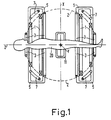
- the nuclear spin tomograph shown schematically in FIG. 1 contains an arrangement consisting of four coils 1 for generating a homogeneous stationary magnetic field which can be of the order of a few tenths to a few T. This field runs in the z direction of a Cartesian coordinate system.
- the coils 1 arranged concentrically to the z-axis can be arranged on a spherical surface 2.
- the patient 20 to be examined is located inside these coils.
- each coil 3 is preferably arranged on the same spherical surface. Furthermore, four coils 7 are provided, which generate a magnetic gradient field Gx, which also runs in the z direction, but whose gradient runs in the x direction.
- a magnetic gradient field Gy running in the z-direction with a gradient in the y-direction is generated by four coils 5, which can be identical to the coils 7, but which are arranged spatially offset from one another by 90 °. Only two of these four coils 5 are shown in FIG.
- each of the three coil arrangements 3, 5 and 7 for generating the magnetic gradient fields Gz, Gy and Gx is arranged symmetrically to the spherical surface 2, the field strength in the spherical center, which also forms the coordinate origin of the mentioned Cartesian x, y, z coordinate system, is only through determines the stationary homogeneous magnetic field of the coil arrangement 1.
- the high-frequency coil is supplied with a high-frequency modulated current from a high-frequency generator during each high-frequency pulse. - Following one or more high-frequency pulses, the high-frequency coil 11 is used to receive the echo signals generated by nuclear magnetic resonance in the examination area. Instead, a separate high-frequency receiving coil could also be used.
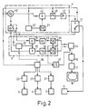
- the high-frequency coil 11 is connected on the one hand to a high-frequency generator 4 and on the other hand to a high-frequency receiver 6 via a switching device 12.
- the high-frequency generator 4 contains a digitally controllable high-frequency oscillator 40, which has vibrations with a frequency equal to the Larmor frequency of those atomic nuclei whose spatial distribution in the layer is to be determined at the field strength generated by the coils 1.
- the output of the oscillator 40 is connected to an input of a mixer 43.
- the mixer 43 is supplied with a second input signal from a digital-to-analog converter 44, the input of which is connected to a digital memory 45. Controlled by a control device 15, a sequence of digital data words representing a frequency-modulated signal is read out of the memory 45.
- the multiplicative mixer 43 generates as the output signal a signal proportional to the product of the signals at its inputs; the frequency-modulated signal is thus modulated onto the carrier.
- the output signal of the mixer 43 is fed via a switch 46 controlled by the control device 15 to a high-frequency power amplifier 47, the output of which is connected to the switching device 12. This is also controlled by the control device 15.
- the receiver 6 contains a high-frequency amplifier 60, which is connected to the switching device and to which the echo signals induced in the high-frequency coil 11 and caused by nuclear magnetic resonance are supplied if the switching device 12 is controlled accordingly.
- the amplifier 60 has a mute input controlled by the control device 15, via which it can be blocked, so that the gain is practically zero.
- the output of amplifier 60 is connected to the first inputs of two multiplicative mixer stages 61 and 62, each of which supplies an output signal corresponding to the product of their input signals.
- a signal with the frequency of the oscillator 40 is fed to the second inputs of the mixer stage 61 and 62, with a phase shift of 90 ° between the signals at the two inputs. This phase shift is generated with the aid of a 90 ° phase shifter 48, the output of which is connected to the input of the mixer 62 and the input of which is connected to the input of the mixer 61 and to the output of the oscillator 40.
- the output signals of the mixer 61 and 62 are each via low-pass filters 63 and 64, which suppress the frequency supplied by the oscillator 40 and all frequencies above it and allow low-frequency components to pass through Analog-digital converter 65 and 66 supplied.
- This converts the analog signals of the circuit 61... 64 forming a quadrature demodulator into digital data words which are fed to a memory 14.
- the analog-to-digital converters 65 and 66 and the memory 14 receive their clock pulses from a clock pulse generator 16, which can be blocked or released by the control device 15 via a control line, so that only in a measurement interval defined by the control device 15 is that of the High-frequency coil 11 supplied, transposed into the low-frequency range signals can be converted into a sequence of digital data words and stored in the memory 14.
- the three coil arrangements 3, 5 and 7 are each supplied with a current by current generators 23, 25 and 27, the course of which can be controlled by the control unit 15.
- the data words or samples stored in the memory 14 are fed to a computer 17, which determines the spatial distribution of the nuclear magnetization in the layer under investigation and the determined distribution on a suitable display unit, e.g. a monitor 18.
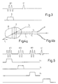
- HF1 (first line) denotes a frequency-modulated high-frequency pulse.
- a magnetic gradient field G is switched on (second line), for example in that the current generator 23 supplies a current for the gradient coil arrangement 3 during the high-frequency pulse.
- the high-frequency pulse HF1 which is a 90 ° high-frequency pulse, in conjunction with the magnetic gradient field G, causes that in the examination region 20 on both sides of a layer determined by the frequency of the oscillator 40, the nuclear magnetization is excited and dephased.
- the nuclear magnetization is excited in the entire examination area by a further high-frequency pulse HF following the first high-frequency pulse HF1, in which no magnetic gradient field is switched on.
- a further high-frequency pulse HF following the first high-frequency pulse HF1, in which no magnetic gradient field is switched on.
- the nuclear magnetization outside the layer is already dephased by the high-frequency pulse HF1
- only the nuclear magnetization within the layer makes a contribution to the nuclear magnetic resonance signal occurring after the high-frequency pulse HF.
- the high-frequency pulse HF which is preferably designed as a 90 ° high-frequency pulse
- two or more further high-frequency pulses can also be generated within a sequence.
- FIG. 4 a shows the examination object 20 and the layer S running perpendicular to the plane of the drawing, which results when the gradient of the magnetic gradient field runs in the horizontal direction.
- the Larmor frequency changes linearly from left to right in the examination area defined by object 20. It is f0 in the middle of layer S; on the left or right edge of the layer it is f1 or f2.
- a sequence of data words is stored in the memory 45 (FIG. 2), which, when the memory content is read out by the control unit 15 and processed by the digital-to-analog converter 44, results in a signal whose frequency is linear from a first value , the difference f2 - f0 corresponds to a second value which corresponds to the difference f4 - f0.
- the rate of change of the frequency is dimensioned such that the specified range is only run through once during the duration (e.g. 5 ms) of the high-frequency pulse HF1.
- the instantaneous frequency of the output signal of the digital-to-analog converter 44 is small compared to the Larmor frequency.
- This signal can therefore be stored in the memory 45 with relatively few data words, the envelope of this signal is expediently chosen as described in European patent application 85 200 644.
- This signal is mixed in the mixer 43 with the sinusoidal signal of the oscillator 40 tuned to the frequency f0.
- the output signal of the mixer 43 which is proportional to the product of these input signals, therefore contains a component whose frequency changes linearly from a value f2 to a value f.4 (see FIG. 4b) and a component whose frequency spacing to the same extent, but in opposite direction changes, as in the former component, ie from f1 to f3.
- the associated high-frequency pulse HF1 therefore has the result that the Larmor frequencies first appear in the two areas immediately adjacent to the layer and then in the areas further away in the high-frequency pulse HF1.
- the nuclear magnetization thereby excited in these areas is dephased by the fact that the magnetic gradient field G remains switched on beyond this excitation.
- the nuclear magnetization in the parts of the examination area located on both sides of the layer S is therefore out of phase when the magnetic gradient field G is switched off with the high-frequency pulse HF1 - or shortly thereafter if necessary.
- the method shown in Figure 5 is based on the one in J. Magn. Reson. 66 , pages 283 to 294 (1986), the so-called ISIS method, in which up to three 180 ° high-frequency pulses act on an examination area, the nuclear magnetization being inverted in one of three mutually perpendicular layers by each high-frequency pulse.
- the use of the frequency-modulated high-frequency pulses stimulates the nuclear magnetization on both sides of the respective layer, while it remains unchanged in the layer itself.
- the method comprises sequence sequences with eight sequences each.
- Each sequence contains up to three slice-selective frequency-modulated 180 ° high-frequency pulses HF1, HF2 and HF3, and always one non-selective high-frequency pulse HF, which is preferably a 90 ° pulse.
- the eight sequences in a sequence contain the three high-frequency pulses HF1 to HF3 in the eight possible combinations. One of the eight sequences therefore does not contain any of the three high-frequency pulses, while another contains all three high-frequency pulses.
- Each three of the sequences contain only one or two of the high-frequency pulses in different combinations.
- the only sequence of the sequence shown in FIG. 5 comprises only the high-frequency pulse HF1 (first line), which is linked to the magnetic gradient field Gx (second line) and the high-frequency pulse HF3 associated with the magnetic gradient field Gx (fourth line).
- the position of the second high-frequency pulse HF2 which does not occur in this sequence and the associated magnetic gradient field Gy (third line) is indicated by dashed lines in FIG.
- the pulse HF3 is followed by the further high-frequency pulse HF, which covers the entire Stimulates the examination area and generates a nuclear magnetic resonance signal that originates from the entire examination area. This nuclear magnetic resonance signal is sampled, ie the pulse generator 16 is released (cf. fifth line).
- Each of the high-frequency pulses HF1..HF3 inverts the nuclear magnetization on both sides of a layer which is perpendicular to the direction of the gradient associated with the high-frequency pulse.
- the nuclear magnetization is not inverted by any of the high-frequency pulses.
- four of the sequences have an inverting effect and the other four have a non-inverting effect. Therefore, if one adds the nuclear magnetic resonance signals generated in the eight sequences of a sequence sequence, only the mentioned cutting area makes a contribution, while the portion of the nuclear magnetic resonance signals originating from the other areas compensate each other.
- the high-frequency pulses HF1 and HF3 are each generated in the same way as described with reference to FIGS. 3 and 4a and b. However, their energy content is larger, so that there is a flip angle of 180 °. In this case, dephasing the nuclear magnetization is neither possible nor necessary; only the nuclear magnetization is inverted on both sides of a layer by the frequency-modulated 180 ° high-frequency pulses in this way.
Abstract
Description
Die Erfindung betrifft ein Verfahren zur Bestimmung der Kernmagnetisierungsverteilung, bei dem in Anwesenheit eines homogenen stationären Magnetfeldes mehrere Sequenzen auf einen Untersuchungsbereich einwirken, wobei jede Sequenz einen Hochfrequenzimpuls enthält, durch den in Verbindung mit einem magnetischen Gradientenfeld die Kernmagnetisierung in den beiderseits einer zu untersuchenden Schicht befindlichen Bereichen angeregt und ggf. dephasiert wird, sowie eine Anordnung zur Durchführung dieses Verfahrens.The invention relates to a method for determining the nuclear magnetization distribution, in which, in the presence of a homogeneous stationary magnetic field, several sequences act on an examination area, each sequence containing a high-frequency pulse, by means of which, in conjunction with a magnetic gradient field, the nuclear magnetization is located on both sides of a layer to be examined Areas is stimulated and possibly dephased, as well as an arrangement for performing this method.
Ein solches Verfahren und eine solche Anordnung sind aus der DE-OS 36 04 281 bekannt. Dabei kann mit einem oder mit zwei aufeinander folgenden Hochfrequenzimpulsen in Verbindung mit einem magnetischen Gradientenfeld, die Kernmagnetisierung in den Bereichen beiderseits einer zu untersuchenden Schicht angeregt und dephasiert werden.Such a method and such an arrangement are known from DE-OS 36 04 281. The nuclear magnetization in the areas on both sides of a layer to be examined can be excited and dephased with one or with two successive high-frequency pulses in connection with a magnetic gradient field.
Bei dem benannten Verfahren wird ein amplitudenmodulierter Hochfrequenzimpuls dadurch erzeugt, daß in einem Modulator in an sich bekannter Weise, die Schwingungen eines Oszillators mit einem Hüllkurvensignal multipliziert werden, das dem zeitlichen Verlauf der Amplitude des Oszillatorsignals entspricht. Ein derartiger Hochfrequenzimpuls hat die Eigenschaft, daß die erforderliche Hochfrequenzspitzenleistung um so größer ist, je dicker der dadurch zu beeinflußende Bereich ist. Aus diesem Grund sind für das bekannte Verfahren relativ hohe Spitzenleistungen erforderlich.In the named method, an amplitude-modulated high-frequency pulse is generated in that the oscillations of an oscillator are multiplied in a modulator in a manner known per se by an envelope signal which corresponds to the time course of the amplitude of the oscillator signal. Such a high-frequency pulse has the property that the thicker the area to be influenced, the greater the required high-frequency peak power. For this reason, relatively high peak performances are required for the known method.
Aufgabe der Erfindung ist es, ein Verfahren der eingangs genannten Art zu schaffen, das mit einer geringeren Hochfrequenzspitzenleistung auskommen kann. Diese Aufgabe wird erfindungsgemäß dadurch gelöst, daß auf einen Träger dessen Frequenz der Larmorfrequenz in der Mitte der zu untersuchenden Schicht entspricht ein Signal moduliert wird, dessen Frequenz sich in einem Bereich ändert, der der Differenz zwischen dieser Larmorfrequenz und den Larmorfrequenzen in einem der Bereiche entspricht.The object of the invention is to provide a method of the type mentioned at the outset which can manage with a lower high-frequency peak power. This object is achieved in that a signal is modulated onto a carrier whose frequency corresponds to the Larmor frequency in the middle of the layer to be examined, the frequency of which changes in a range which corresponds to the difference between this Larmor frequency and the Larmor frequencies in one of the ranges .
Bei der Erfindung wird also ein frequenzmodulierter Hochfrequenzimpuls verwendet. Es ist an sich bekannt, daß zur Erzeugung frequenzmodulierter Hochfrequenzimpulse eine niedrigere Spitzenleistung benötigt wird, als zur Erzeugung von amplitudenmodulierten Hochfrequenzimpulsen für den gleichen Flipwinkel (EP-OS 85 200 644.4). Während nämlich die Dauer eines amplitudenmodulierten Hochfrequenzimpulses seiner Bandbreite und damit der Dicke des durch ihn anzuregenden Bereiches umgekehrt proportional ist, kann die Dauer eines frequenzmodulierten Impulses weitgehend unabhängig von der Bandbreite gewählt werden; sie läßt sich daher so groß bemessen, das nur noch eine vergleichsweise niedrige Hochfrequenzspitzenleistung erforderlich ist.A frequency-modulated high-frequency pulse is therefore used in the invention. It is known per se that a lower peak power is required to generate frequency-modulated high-frequency pulses than to generate amplitude-modulated high-frequency pulses for the same flip angle (EP-OS 85 200 644.4). While the duration of an amplitude-modulated high-frequency pulse is inversely proportional to its bandwidth and thus the thickness of the area to be excited by it, the duration of a frequency-modulated pulse can be chosen largely independently of the bandwidth; it can therefore be dimensioned so large that only a comparatively low high-frequency peak power is required.
Üblicherweise ist zur Erzeugung eines frequenzmodulierten Hochfrequenzimpulses ein Frequenzmodulator erforderlich. Ein solcher Frequenzmodulator kann - vergl. Fig.5 der EP-OS 85 200 644 - zwei als multiplikative Mischer wirksame Modulatoren enthalten, deren anderem Eingang jeweils ein Signal zugeführt wird, das dem Realteil bzw. dem Imaginärteil des frequenzmodulierten Signales entspricht. Die in den üblichen Kernspinuntersuchungsgeräten vorhandenen Modulatoren besitzen jedoch nur eine einzige multiplikativ wirkende Mischstufe, mit der eine der artige Frequenzmodulation nicht durchgeführt werden kann. Das erfindungsgemäße Verfahren läßt sich jedoch mit einem derartigen Modulator durchführen. Dem liegen folgende Überlegungen zugrunde:A frequency modulator is usually required to generate a frequency-modulated high-frequency pulse. Such a frequency modulator can - see FIG. 5 of EP-OS 85 200 644 - contain two modulators that act as multiplicative mixers, the other input of which is fed a signal that corresponds to the real part or the imaginary part of the frequency-modulated signal. However, the modulators present in the usual magnetic resonance examination devices only have a single multiplicative mixing stage with which one of the like frequency modulation can not be performed. However, the method according to the invention can be carried out with such a modulator. This is based on the following considerations:
Ein frequenzmodulierter Hochfrequenzimpuls, der in einem der beiden Bereiche beiderseits einer zu untersuchenden Schicht die Kernmagnetisierung vom Rand dieser Schicht bis zum Ende des Empfangs- bzw. des Sendebereichs der Hochfrequenzspule beeinflußt, läßt sich als komplexe Funktion bezüglich der Lamorfrequenz in der Mitte der zu untersuchenden Schicht darstellen. Ein in dieser Darstellung konjugiert komplexer Hochfrequenzimpuls, d.h. ein Impuls mit gleicher Amplitude, gleichem Realteil und invertiertem Imaginärteil würde nun gerade die negativen Frequenzen, bezogen auf die Frequenz in der Mitte der Schicht, durchlaufen. Das heißt, er würde in der entgegengesetzten Richtung einen Bereich vom anderen Rand der Schicht bis zum anderen Ende des Sende- bzw. Empfangsbereiches des Objekts durchlaufen. Wenn der Frequenzabstand zwischen den beiden Rändern der Schicht groß genug ist und die verwendete Hochfrequenzfeldstärke nicht zu groß ist, können beide Hochfrequenzimpulse gleichzeitig auf den Untersuchungsbereich gegeben werden, ohne sich gegenseitig zu beeinflußen. Dies entspricht einer Addition der beiden zueinander konjugiert komplexen Hochfrequenzimpulse bei der sich die Realteile addieren und die Imaginärteile kompensieren. Es ist daher lediglich erforderlich den Realteil des frequenzmodulierten Signals auf den Träger in einem Amplitudenmodulationsvorgang zu modulieren, was mit einem für diese Zwecke üblichen Amplitudenmodulator erfolgen kann.A frequency-modulated high-frequency pulse, which influences the nuclear magnetization from the edge of this layer to the end of the reception or transmission range of the high-frequency coil in one of the two areas on either side of a layer to be examined, can be a complex function with regard to the lamor frequency in the middle of the layer to be examined represent. A complex high frequency pulse conjugated in this representation, i.e. a pulse with the same amplitude, the same real part and an inverted imaginary part would now run through the negative frequencies, based on the frequency in the middle of the layer. This means that it would pass through an area in the opposite direction from the other edge of the layer to the other end of the transmission or reception area of the object. If the frequency spacing between the two edges of the layer is large enough and the high-frequency field strength used is not too great, both high-frequency pulses can be applied to the examination area at the same time without influencing one another. This corresponds to an addition of the two complex high-frequency pulses conjugated to each other, in which the real parts add up and the imaginary parts compensate. It is therefore only necessary to modulate the real part of the frequency-modulated signal on the carrier in an amplitude modulation process, which can be done with an amplitude modulator that is customary for these purposes.
Der Hochfrequenzimpuls kann sowohl ein 90°-Hochfrequenzimpuls als auch ein 180°-Hochfrequenzimpuls sein. Durch einen 90°-Hochfrequenzimpuls werden die beiden Bereiche beiderseits der Schicht angeregt, während die Schicht selbst nicht angeregt wird. Um die Kernmagnetisierungsverteilung in der Schicht zu untersuchen, muß die Kernmagnetisierung in den Bereichen beiderseits der Schicht dephasiert werden und anschließend wenigstens ein nichtselektiver Hochfrequenzimpuls erzeugt werden, der die Kernmagnetisierung im gesamten Hochfrequenzbereich beeinflußt. Da die Kernmagnetisierung außerhalb der Schicht aber bereits dephasiert ist, liefert nur die Schicht selbst einen Beitrag zu dem mit diesem Hochfrequenzimpuls bzw. diesen Hochfrequenzimpulsen verbundenen Kernspinresonanzsignalen.The high-frequency pulse can be either a 90 ° high-frequency pulse or a 180 ° high-frequency pulse. The two areas are separated by a 90 ° high-frequency pulse excited on both sides of the layer while the layer itself is not excited. In order to investigate the nuclear magnetization distribution in the layer, the nuclear magnetization in the regions on both sides of the layer must be dephased and then at least one non-selective high-frequency pulse must be generated which influences the nuclear magnetization in the entire high-frequency range. However, since the nuclear magnetization outside the layer is already out of phase, only the layer itself makes a contribution to the nuclear magnetic resonance signals associated with this high-frequency pulse or these high-frequency pulses.
Die erforderliche Dephasierung in den Bereichen beiderseits der Schicht läßt sich nach einer Weiterbildung der Erfindung besonders leicht dadurch erreichen, daß die Frequenz des Signales so geändert wird, daß der Betrag der Differenz zeitlich zunimmt. Hierbei schreitet die Anregung in den Bereichen von innen nach außen fort. Da während des gesamten Hochfrequenzimpulses ein magnetisches Gradientenfeld anliegt, ist bei dieser Ausführungsform die Kernmagnetisierung unmittelbar beiderseits der Schicht bereits am Ende des Hochfrequenzimpulses dephasiert, so daß das magnetische Gradientenfeld in diesem Fall am Ende des Hochfrequenzimpulses - oder kurz danach - abgeschaltet werden kann.According to a further development of the invention, the required dephasing in the areas on both sides of the layer can be achieved particularly easily by changing the frequency of the signal in such a way that the amount of the difference increases over time. Here, the stimulation progresses in the areas from the inside out. Since a magnetic gradient field is present during the entire high-frequency pulse, in this embodiment the nuclear magnetization immediately on both sides of the layer is already dephased at the end of the high-frequency pulse, so that the magnetic gradient field can in this case be switched off at the end of the high-frequency pulse - or shortly thereafter.
Eine Anordnung zur Durchführung des erfindungsgemäßen Verfahrens, die versehen ist mit einem Magneten zur Erzeugung eines homogenen stationären Magnetfeldes, einer Gradientenspulenanordnung zur Erzeugung von in Richtung des stationären Magnetfeldes verlaufenden Magnetfeldern mit in verschiedenen Richtungen verlaufenden Gradienten, einer Hochfrequenzspulenanordnung zur Erzeugung eines hochfrequenten, zum stationären Magnetfeld senkrechten Magnetfeldes und einem Hochfrequenzgenerator, der mit der Hochfrequenzspulenanordnung koppelbar ist und einen als multiplikative Mischstufe wirksamen Modulator enthält, ist dadurch gekennzeichnet, daß ein Signalerzeuger vorgesehen ist, der ein frequenzmoduliertes Signal liefert und daß in dem Modulator die Schwingungen eines auf die Larmorfrequenz abstimmbaren Oszillators mit dem Signal multipliziert werden.An arrangement for performing the method according to the invention, which is provided with a magnet for generating a homogeneous stationary magnetic field, a gradient coil arrangement for generating magnetic fields running in the direction of the stationary magnetic field with gradients running in different directions, a high-frequency coil arrangement for generating a high-frequency, stationary magnetic field vertical Magnetic field and a high-frequency generator, which can be coupled to the high-frequency coil arrangement and contains a modulator which acts as a multiplicative mixing stage, is characterized in that a signal generator is provided which delivers a frequency-modulated signal and that in the modulator the vibrations of an oscillator which can be tuned to the Larmor frequency are combined with the Signal to be multiplied.
Nach einer bevorzugten Weiterbildung ist dabei vorgesehen, daß ein Speicher vorgesehen ist, in den das Signal als Folge digitaler Datenworte gespeichert ist, und daß der Speicher über ein Digital-Analog-Wandler mit einem Eingang des Modulators gekoppelt ist.According to a preferred development, it is provided that a memory is provided in which the signal is stored as a sequence of digital data words, and that the memory is coupled to an input of the modulator via a digital-to-analog converter.
Die Erfindung wir nachstehend an Hand der Zeichnungen näher erläutert. Es zeigen:
- Fig.1 ein Kernspinuntersunchungsgerät, bei den die Erfindung anwendbar ist,
- Fig.2 ein Blockschaltbild eines solchen Gerätes,
- Fig.3 die zeitliche Lage verschiedener Signale bei einer Sequenz, bei der die Erfindung anwendbar ist,
- Fig.4a die räumliche Zuordnung der Larmorfrequenzen,
- Fig.4b den zeitlichen Verlauf der Frequenz bei einem Hochfrequenzimpuls,
- Fig.5 eine weitere Sequenz, bei der die Erfindung anwendbar ist.
- 1 shows a magnetic resonance device, to which the invention is applicable,
- 2 shows a block diagram of such a device,
- 3 shows the temporal position of various signals in a sequence in which the invention is applicable,
- 4a the spatial assignment of the Larmor frequencies,
- 4b shows the time course of the frequency in the case of a high-frequency pulse,
- 5 shows a further sequence in which the invention is applicable.
Der in Fig.1 schematisch dargestellte Kernspin-Tomograph enthält ein aus vier Spulen 1 bestehende Anordnung zur Erzeugung eines homogenen stationären Magnetfeldes, das in der Größenordnung von einigen Zehntel T bis einigen T liegen kann. Dieses Feld verläuft in z-Richtung eines kartesischen Koordinatensystems. Die zur z-Achse konzentrisch angeordneten Spulen 1 können auf einer Kugeloberfläche 2 angeordnet sein. Im Inneren dieser Spulen befindet sich der zu untersuchende Patient 20.The nuclear spin tomograph shown schematically in FIG. 1 contains an arrangement consisting of four
Zur Erzeugung eines in z-Richtung verlaufenden und sich in dieser Richtung linear ändernden Magnetfeldes Gz sind vier Spulen 3 vorzugsweise auf der gleichen Kugeloberfläche angeordnet. Weiterhin sind vier Spulen 7 vorgesehen, die ein ebenfalls in z-Richtung verlaufendes magnetisches Gradientenfeld Gx erzeugen, dessen Gradient jedoch in x-Richtung verläuft. Ein in z-Richtung verlaufendes magnetsiches Gradientenfeld Gy mit einem Gradienten in y-Richtung wird von vier Spulen 5 erzeugt, die mit den Spulen 7 identisch sein können, die jedoch diesen gegenüber um 90° räumlich versetzt angeordnet sind. Von diesen vier Spulen 5 sind in Fig.1 nur zwei dargestellt.In order to generate a magnetic field Gz running in the z direction and changing linearly in this direction, four
Da jede der drei Spulenanordnungen 3, 5 und 7 zur Erzeugung der magnetischen Gradientenfelder Gz, Gy und Gx symmetrisch zur Kugeloberfläche 2 angeordnet ist, ist die Feldstärke im Kugelzentrum das gleichzeitig den Koordinatenursprung des erwähnten kartesischen x, y, z-Koordiantensystem bildet, nur durch das stationäre homogene Magnetfeld der Spulenanordnung 1 bestimmt. Weiterhin ist eine Hochfrequenzspule 11 symmetrisch zur Ebene z = 0 des Koordinatensystems angeordnet, die so ausgebildet ist, das damit ein im wesentlichen homogenes und in x-Richtung, d.h. senkrecht zur Richtung des stationären homogenen Magnetfeldes verlaufendes hochfrequentes Magnet feld erzeugt wird. Der Hochfrequenzspule wird wärend jedes Hochfrequenzimpulses ein hochfrequenter modulierter Strom von einem Hochfrequenzgenerator zugeführt. - Im Anschluß an einen oder mehrere Hochfrequenzimpulse dient die Hochfrequenzspule 11 zum Empfangen der durch Kernspinresonanz im Untersuchungsbereich erzeugten Echosignale. Stattdessen könnte aber auch eine gesonderte Hochfrequenz-Empfangsspule verwendet werden.Since each of the three
Fig.2 zeigt ein vereinfachtes Blockschaltbild dieses Kernspintomographen. Die Hochfrequenzspule 11 ist über eine Umschalteinrichtung 12 einerseits an einen Hochfrequenzgenerator 4 und andererseits an einen Hochfrequenzempfänger 6 angeschlossen.2 shows a simplified block diagram of this magnetic resonance tomograph. The high-
Der Hochfrequenzgenerator 4 enthält einen in seiner Frequenz digital steuerbaren Hochfrequenzosillator 40, der Schwingungen mit einer Frequenz gleich der Larmorfrequenz derjenigen Atomkerne, deren räumliche Verteilung in der Schicht ermittelt werden soll, bei der von den Spulen 1 erzeugten Feldstärke aufweist. Die Larmorfrequenz f berechnet sich bekanntlich nach der Beziehung f = cB, wobei B die magnetische Induktion in dem stationären homogenen Magnetfeld darstellt und c das gyromagnetische Verhältnis, das beispielsweise für Wasserstoffprotonen 42,56 MHz/T und für das Natriumisotop Na 23 11,26 MHz/T beträgt. Der Ausgang des Oszillators 40 ist mit einem Eingang einer Mischstufe 43 verbunden. Der Mischstufe 43 wird ein zweites Eingangssignal von einem Digital-Analog-Wandler 44 zugeführt, dessen Eingang mit einem digitalen Speicher 45 verbunden ist. Aus dem Speicher 45 wird - gesteuert durch eine Steuereinrichtung 15 - eine Folge von ein frequenzmoduliertes Signal darstellenden digitalen Datenworten ausgelesen.The high-frequency generator 4 contains a digitally controllable high-
Die multiplikative Mischstufe 43 erzeugt als Ausgangssignal ein dem Produkt der Signale an ihren Eingängen proportionales Signal; das frequenzmodulierte Signal wird also auf den Träger aufmoduliert. Das Ausgangssignal der Mischstufe 43 wird über einen von der Steuereinrichtung 15 gesteuerten Schalter 46 einem Hochfrequenz-Leistungsverstäker 47 zugeführt, dessen Ausgang mit der Umschalteinrichtung 12 verbunden ist. Diese wird ebenfalls durch die Steuereinrichtung 15 gesteuert.The
Der Empfänger 6 enthält einen Hochfrequenzverstärker 60, der mit der Umschalteinrichtung verbunden ist und dem die in der Hochfrequenzspule 11 induzierten, durch Kernspinresonanz hervorgerufenen Echosignale zugeführt werden, wenn die Umschalteinrichtung 12 entsprechend gesteuert ist. Der Verstärker 60 besitzt einen von der Steuereinrichtung 15 gesteuerten Stummschalteingang, über den er gesperrt werden kann, so daß die Verstärkung praktisch Null ist. Der Ausgang des Verstärkers 60 ist mit den ersten Eingängen zweier multiplikativer Mischstufen 61 und 62 verbunden, die jeweils ein dem Produkt ihrer Eingangssignale entsprechendes Ausgangssignal liefern. Den zweiten Eingängen der Mischstufe 61 und 62 wird ein Signal mit der Frequenz des Oszillators 40 zugeführt, wobei zwischen den Signalen an den beiden Eingängen eine Phasenverschiebung von 90° besteht. Diese Phasenverschiebung wird mit Hilfe eines 90°-Phasendrehgliedes 48 erzeugt, dessen Ausgang mit dem Eingang der Mischstufe 62 und dessen Eingang mit dem Eingang der Mischstufe 61 und mit dem Ausgang des Oszillators 40 verbunden ist.The receiver 6 contains a high-
Die Ausgangssignale der Mischstufe 61 und 62 werden über Tiefpässe 63 und 64, die die vom Oszillator 40 gelieferte Frequenz sowie alle darüber liegenden Frequenzen unterdrückt und niederfrequente Anteile durchlassen, je einem Analog-Digital-Wandler 65 bzw. 66 zugeführt. Dieser setzt die analogen Signale der einen Quadratur-Demodulator bildenden Schaltung 61...64 in digitale Datenworte um, die einem Speicher 14 zugeführt werden. Die Analog-Digital-Wandler 65 und 66 sowie der Speicher 14 erhalten ihre Taktimpulse von einem Taktimpulsgenerator 16, der über eine Steuerleitung von der Steuereinrichtung 15 blockiert bzw. freigegeben werden kann, so daß nur in einem durch die Steuereinrichtung 15 definierten Meßintervall die von der Hochfrequenzspule 11 gelieferten, in den Niederfrequenzbereich transponierten Signale in eine Folge digitaler Datenworte umgesetzt und in dem Speicher 14 gespeichert werden können.The output signals of the
Die drei Spulenanordnungen 3, 5 und 7 werden von Stromgeneratoren 23, 25 und 27 jeweils mit einem Strom versorgt, dessen zeitlicher Verlauf durch die Steuereinheit 15 steuerbar ist. Die im Speicher 14 gespeicherten Datenworte bzw. Abtastwerte werden einem Rechner 17 zugeführt, der daraus die räumliche Verteilung der Kernmagnetisierung in der untersuchten Schicht ermittelt und die ermittelte Verteilung an einer geeigneten Wiedergabeeinheit, z.B. einem Monitor 18, ausgibt.The three
In Fig.3 ist die zeitliche Lage verschiedener Signale bei einem Teil einer Sequenz dargestellt, bei der die Erfindung anwendbar ist. Mit HF1 (erste Zeile) ist dabei ein frequenzmodulierter Hochfrequenzimpuls bezeichnet. Während dieses Hochfrequenzimpulses ist ein magnetisches Gradientenfeld G eingeschaltet (zweite Zeile), beispielsweise dadurch, daß während des Hochfrequenzimpulses der Stromgenerator 23 einen Strom für die Gradientenspulenanordnung 3 liefert. Der Hochfrequenzimpuls HF1, der einen 90°-Hochfrequenzimpuls ist, bewirkt in Verbindung mit dem magnetischen Gradientenfeld G, daß in dem Untersuchungs bereich 20 beiderseits einer durch die Frequenz des Oszillators 40 bestimmten Schicht die Kernmagnetisierung angeregt und dephasiert wird.3 shows the temporal position of various signals in a part of a sequence in which the invention can be used. HF1 (first line) denotes a frequency-modulated high-frequency pulse. During this high-frequency pulse, a magnetic gradient field G is switched on (second line), for example in that the
Durch einen weiteren Hochfrequenzimpuls HF im Anschluß an den ersten Hochfrequenzimpuls HF1, bei dem kein magnetisches Gradientenfeld eingeschaltet ist, wird die Kernmagnetisierung im gesamten Untersuchungsbreich angeregt. Da die Kernmagnetisierung außerhalb der Schicht aber bereits durch den Hochfrequenzimpuls HF1 dephasiert ist, liefert nur die Kernmagnetisierung innerhalb der Schicht einen Beitrag zu dem nach dem Hochfrequenzimpuls HF auftretenden Kernresonanzsignal. An Stelle des vorzugsweise als 90°-Hochfrequenzimpuls gestalteten Hochfrequenzimpulses HF können auch zwei oder mehrere weitere Hochfrequenzimpulse innerhalb einer Sequenz erzeugt werden. Durch Einschaltung magnetischer Gradientenfelder zwischen oder nach diesen Hochfreqenzimpulsen läßt sich mit einer Vielzahl von Sequenzen mit von Sequenz zu Sequenz geänderten Parametern, die Kernmagnetisierungsverteilung innerhalb der Schicht bestimmen.The nuclear magnetization is excited in the entire examination area by a further high-frequency pulse HF following the first high-frequency pulse HF1, in which no magnetic gradient field is switched on. However, since the nuclear magnetization outside the layer is already dephased by the high-frequency pulse HF1, only the nuclear magnetization within the layer makes a contribution to the nuclear magnetic resonance signal occurring after the high-frequency pulse HF. Instead of the high-frequency pulse HF, which is preferably designed as a 90 ° high-frequency pulse, two or more further high-frequency pulses can also be generated within a sequence. By inserting magnetic gradient fields between or after these high-frequency pulses, the nuclear magnetization distribution within the layer can be determined with a large number of sequences with parameters changed from sequence to sequence.
Es ist aber auch möglich, innerhalb einer Sequenz zunächst drei aufeinander folgende frequenzmodulierte 90°-Hochfrequenzimpulse zu erzeugen, während jedes dieser Hochfrequenzimpulse ein magnetisches Gradientenfeld mit von Impuls zu Impuls um 90° gedrehter Gradientenrichtung einzuschalten (dadurch wird die Kernmagnetisierung überall außerhalb eines durch die drei aufeinander senkrechten Schichten definierten Volumenbereichs dephasiert) und dann einen nichtselektiven Hochfrequenzimpuls zu erzeugen. Dieser erzeugt ein Kernresonanzsignal, das durch die Kernmagnetisierung - und deren spektrale Verteilung - in dem Volumenelement bestimmt ist.However, it is also possible to first generate three successive frequency-modulated 90 ° high-frequency pulses within a sequence, while each of these high-frequency pulses switch on a magnetic gradient field with a gradient direction rotated by 90 ° from pulse to pulse (this means that the nuclear magnetization is everywhere outside one by the three layers perpendicular to each other dephased defined volume range) and then to generate a non-selective high-frequency pulse. This generates a nuclear magnetic resonance signal, which is determined by the nuclear magnetization - and its spectral distribution - in the volume element.
Fig.4a zeigt das Untersuchungsobjekt 20 und die senkrecht zur Zeichenebene verlaufende Schicht S, die sich ergibt, wenn der Gradient des magnetischen Gradientenfeldes in horizontaler Richtung verläuft. Bei einem konstanten Gradienten ändert sich bekanntlich die Larmorfrequenz in dem durch das Objekt 20 definierten Untersuchungsbereich linear von links nach rechts. Sie beträgt f₀ in der Mitte der Schicht S; am linken bzw. am rechten Rand der Schicht beträgt sie f₁ bzw. f₂. Der linke bzw. rechte Rand des Untersuchungsbereiches liegt innerhalb des durch die Larmorfrequenzen f₃ bzw. f₄ definierten Bereiches, wobei gelten soll,
f₄ - f₂ = f₁ - f₃.4 a shows the
f₄ - f₂ = f₁ - f₃.
In dem Speicher 45 (Fig.2) ist eine Folge von Datenwörtern gespeichert, die bei der durch die Steuereinheit 15 gesteuerten Auslesung des Speicherinhalts und dessen Verarbeitung durch den Digital-Analog-Wandler 44 ein Signal ergibt, dessen Frequenz sich linear von einem ersten Wert, der Differenz f₂ - f₀ entspricht bis zu einem zweiten Wert ändert, der der Differenz f₄ - f₀ entspricht. Die Änderungsgeschwindigkeit der Frequenz ist dabei so bemessen, daß der angegebene Bereich, während der Dauer (z.B. 5 ms) des Hochfrequenzimpulses HF1 gerade einmal durchlaufen wird.A sequence of data words is stored in the memory 45 (FIG. 2), which, when the memory content is read out by the
Da die durch das magnetische Gardientenfeld G bewirkten Änderungen des durch die Spulen 1 erzeugten homogenen stationären Magnetfeldes klein sind im Vergleich zur Feldstärke dieses Magnetfeldes ist die Momentanfrequenz des Ausgangssignals des Digital-Analog-Wandlers 44 klein im Vergleich zur Larmorfrequenz. Dieses Signal kann daher mit verhältnismäßig wenig Datenworten in dem Speicher 45 gespeichert werden, wobei die Umhüllende dieses Signales zweckmäßiger Weise so gewählt wird, wie in der Europäischen Patentanmeldung 85 200 644 beschrieben.Since the changes caused by the magnetic gradient field G of the homogeneous stationary magnetic field generated by the
Dieses Signal wird in der Mischstufe 43 mit dem sinusförmigen Signal des auf die Frequenz f₀ abgestimmten Oszillators 40 gemischt. Das dem Produkt dieser Eingangssignale proportionale Ausgangssignal der Mischstufe 43 enthält daher eine Komponente, deren Frequenz sich linear von einem Wert f₂ zu einem Wert f₄ ändert (vergl. Fig.4b) und eine Komponente, deren Frequenzabstand zu f₀ sich in gleicher Maße, jedoch in entgegengesetzter Richtung ändert, wie bei der erstgenannten Komponente, d.h. von f₁ nach f₃. Der damit einhergehende Hochfrequenzimpuls HF1 hat also zur Folge, daß die Larmorfrequenzen zunächst der beiden der Schicht unmittelbar benachbarten Bereiche und dann der weiter entfernt liegenden Bereiche in dem Hochfrequenzimpuls HF1 auftreten. Die dadurch in diesen Bereichen angeregte Kernmagnetisierung wird aber dadurch dephasiert, daß das magnetische Gradientenfeld G über diese Anregung hinaus eingeschaltet bleibt. Die Kernmagnetisierung in den beiderseits der Schicht S befindlichen Teilen des Untersuchungsbereiches ist also dephasiert, wenn das magnetische Gradientenfeld G mit dem Hochfrequenzimpuls HF1 - oder erforderlichenfalls kurz danach - abgeschaltet wird.This signal is mixed in the
Es ist nicht erforderlich, daß die Frequenz sich linear ändert; beispielsweise kann auch eine nach einer Tangens-Hyperbolicus-Funktion verlaufende Frequenzänderung von Nutzen sein, wie sie in Fig.4b mit strichpunktierten Linien angedeutet ist; in diesem Fall sollte die umhüllende des im Speicher 45 gespeicherten Signals mit variabler Frequenz einer Secans-Hyperbolicus-Funktion folgen (J. Chem. Phys. 79, 9 November 1983, Seiten 4643 bis 4644).It is not necessary that the frequency change linearly; For example, a frequency change following a tangent hyperbolic function can also be useful, as is indicated by dash-dotted lines in FIG. 4b; in this case, the envelope of the variable frequency signal stored in the
Das in Fig.5 dargestellte Verfahren basiert auf dem in J. Magn. Reson. 66, Seiten 283 bis 294 (1986) beschriebenen sogenannten ISIS-Verfahren, bei dem bis zu drei 180° Hochfrequenzimpulse auf einen Untersuchungsbereich einwirken, wobei durch jeden Hochfrequenzimpuls die Kernmagnetisierung in einer von drei zueinander senkrechten Schichten invertiert wird. Durch die Anwendung der frequenzmodulierten Hochfrequenzimpulse wird die Kernmagnetisierung beiderseits der jeweiligen Schicht angeregt, während sie in der Schicht selbst unverändert bleibt. Im einzelnen gilt folgendes:The method shown in Figure 5 is based on the one in J. Magn. Reson. 66 , pages 283 to 294 (1986), the so-called ISIS method, in which up to three 180 ° high-frequency pulses act on an examination area, the nuclear magnetization being inverted in one of three mutually perpendicular layers by each high-frequency pulse. The use of the frequency-modulated high-frequency pulses stimulates the nuclear magnetization on both sides of the respective layer, while it remains unchanged in the layer itself. The following applies in particular:
Das Verfahren umfaßt Sequenzenfolgen mit jeweils acht Sequenzen. Jede Sequenz enthält bis zu drei schichtselektive frequenzmodulierte 180°-Hochfrequenzimpulse HF1, HF2 und HF3, sowie immer einen nichtselektiven Hochfrequenzimpuls HF, der vorzugsweise ein 90°-Impuls ist. Die acht Sequenzen einer Sequenzenfolge enthalten die drei Hochfrequenzimpulse HF1 bis HF3 in den acht möglichen Kombinationen. Eine der acht Sequenzen enthält also keinen der drei Hochfrequenzimpulse, während eine andere alle drei Hochfrequenzimpulse enthält. Je drei der Sequenzen enthalten nur jeweils einen bzw. zwei der Hochfrequenzimpulse in unterschiedlicher Kombination.The method comprises sequence sequences with eight sequences each. Each sequence contains up to three slice-selective frequency-modulated 180 ° high-frequency pulses HF1, HF2 and HF3, and always one non-selective high-frequency pulse HF, which is preferably a 90 ° pulse. The eight sequences in a sequence contain the three high-frequency pulses HF1 to HF3 in the eight possible combinations. One of the eight sequences therefore does not contain any of the three high-frequency pulses, while another contains all three high-frequency pulses. Each three of the sequences contain only one or two of the high-frequency pulses in different combinations.
Die in Fig.5 dargestellte einzige Sequenz der Sequenzenfolge umfaßt lediglich den Hochfrequenzimpuls HF1 (erste Zeile), der mit dem magnetischen Gradientenfeld Gx (zweite Zeile) verknüpft ist und den mit dem magnetischen Gradientenfeld Gx (vierte Zeile) einen hergehenden Hochfrequenzimpuls HF3. Die Lage des in dieser Sequenz ausbleibenden zweiten Hochfrequenzimpulsrs HF2 und des damit verknüpften magnetischen Gradientenfeldes Gy (dritte Zeile) ist in Fig.5 gestrichelt angedeutet. Dem Impuls HF3 folgt der weitere Hochfrequenzimpuls HF, der den gesamten Untersuchungsbereich anregt und ein Kernresonanzsignal erzeugt, das aus dem gesamten Untersuchungsbereich stammt. Dieses Kernresonanzsignal wird abgetastet, d.h. es wird (vergl. fünfte Zeile) der Impulsgenerator 16 freigegeben. Durch jeden der Hochfrequenzimpulse HF1..HF3 wird die Kernmagnetisierung beiderseits einer Schicht invertiert, die senkrecht auf der Richtung des mit dem Hochfrequenzimpuls verknüpften Gradienten steht. Infolgedessen wird in dem Schnittbereich, der drei zueinander senkrechten Schichten die Kernmagnetisierung durch keinen der Hochfrequenzimpulse invertiert. Für jede andere Stelle des Untersuchungsbereiches wirken vier der Sequenzen invertierend und die vier anderen nichtinvertierend. Addiert man daher die in den acht Sequenzen einer Sequenzenfolge erzeugten Kernresonanzsignale, dann liefert nur nur der erwähnte Schnittbereich einen Beitrag, während die aus den anderen Bereichen herrührenden Anteil der Kernresonanzsignale sich jeweils kompensieren.The only sequence of the sequence shown in FIG. 5 comprises only the high-frequency pulse HF1 (first line), which is linked to the magnetic gradient field Gx (second line) and the high-frequency pulse HF3 associated with the magnetic gradient field Gx (fourth line). The position of the second high-frequency pulse HF2 which does not occur in this sequence and the associated magnetic gradient field Gy (third line) is indicated by dashed lines in FIG. The pulse HF3 is followed by the further high-frequency pulse HF, which covers the entire Stimulates the examination area and generates a nuclear magnetic resonance signal that originates from the entire examination area. This nuclear magnetic resonance signal is sampled, ie the
Die Hochfrequenzimpulse HF1 und HF3 werden jeweils auf gleiche Weise erzeugt, wie anhand von Fig.3 und 4a und b beschrieben. Jedoch ist ihr Energieinhalt größer, so daß sich ein Flip-Winkel von 180° ergibt. In diesem Fall ist eine Dephasierung der Kernmagnetisierung weder möglich, noch erforderlich; es wird durch die auf diese Weise frequenzmodulierten 180°-Hochfrequenzimpulse lediglich die Kernmagnetisierung jeweils beiderseits einer Schicht invertiert.The high-frequency pulses HF1 and HF3 are each generated in the same way as described with reference to FIGS. 3 and 4a and b. However, their energy content is larger, so that there is a flip angle of 180 °. In this case, dephasing the nuclear magnetization is neither possible nor necessary; only the nuclear magnetization is inverted on both sides of a layer by the frequency-modulated 180 ° high-frequency pulses in this way.
Claims (8)
dadurch gekennzeichnet, daß die Frequenz des Signales so geändert wird, daß der Betrag der Differenz zeitlich zunimmt.2. The method according to claim 1,
characterized in that the frequency of the signal is changed so that the amount of the difference increases in time.
dadurch gekennzeichnet, daß der Hochfrequenzimpuls ein 90°-Hochfrequenzimpuls ist.3. The method according to any one of claims 1 or 2,
characterized in that the radio frequency pulse is a 90 ° radio frequency pulse.
dadurch gekennzeichnet, daß der Hochfrequenzimpuls ein 180°-Hochfrequenzimpuls ist.4. The method according to any one of claims 1 or 2,
characterized in that the radio frequency pulse is a 180 ° radio frequency pulse.
dadurch gekennzeichnet, daß die Frequenz sich zeitlich linear ändert.5. The method according to any one of claims 1 to 4,
characterized in that the frequency changes linearly over time.
dadurch gekennzeichnet, daß die Frequenz des Signals sich zeitlich nach einer Hyperbeltangens-Funktion ändert.6. The method according to any one of claims 1 to 4,
characterized in that the frequency of the signal changes in time according to a hyperbolic tangent function.
dadurch gekennzeichnet, daß ein Signalerzeuger (44,45) vorgesehen ist, der ein frequenzmoduliertes Signal liefert, und daß in dem Modulator die Schwingungen eines auf die Larmorfrequenz abstimmbaren Oszillators mit dem Signal multipliziert werden.7. Arrangement for performing the method according to claim 1, with a magnet for generating a homogeneous stationary magnetic field, a gradient coil arrangement for generating magnetic fields extending in the direction of the stationary magnetic field, with gradients running in different directions, a high-frequency coil arrangement for generating a high-frequency to the stationary magnetic field vertical magnetic field and a high-frequency generator which can be coupled to the high-frequency coil arrangement and contains a modulator which acts as a multiplicative mixing stage,
characterized in that a signal generator (44, 45) is provided which supplies a frequency-modulated signal, and in that the vibrations of an oscillator which can be tuned to the Larmor frequency are multiplied by the signal in the modulator.
dadurch gekennzeichnet, daß der Signalerzeuger einen Speicher (45) enthält, in dem das Signal als Folge digitaler Datenworte gespeichert ist, und einen Digital-Analog-Wandler (44), über den der Speicher (45) mit einem Eingang des Modulators (43) gekoppelt ist.8. Arrangement according to claim 7,
characterized in that the signal generator contains a memory (45) in which the signal is stored as a sequence of digital data words, and a digital-to-analog converter (44) via which the memory (45) with an input of the modulator (43) is coupled.
Applications Claiming Priority (2)
| Application Number | Priority Date | Filing Date | Title |
|---|---|---|---|
| DE3808281 | 1988-03-12 | ||
| DE3808281A DE3808281A1 (en) | 1988-03-12 | 1988-03-12 | PROCEDURE FOR DETERMINING NUCLEAR MAGNETIZATION DISTRIBUTION AND ARRANGEMENT FOR PERFORMING THE PROCEDURE |
Publications (2)
| Publication Number | Publication Date |
|---|---|
| EP0333250A2 true EP0333250A2 (en) | 1989-09-20 |
| EP0333250A3 EP0333250A3 (en) | 1990-12-27 |
Family
ID=6349563
Family Applications (1)
| Application Number | Title | Priority Date | Filing Date |
|---|---|---|---|
| EP19890200546 Withdrawn EP0333250A3 (en) | 1988-03-12 | 1989-03-06 | Method for determining the distribution of nuclear magnetization, and apparatus for carrying out the method |
Country Status (4)
| Country | Link |
|---|---|
| US (1) | US4939461A (en) |
| EP (1) | EP0333250A3 (en) |
| JP (1) | JPH027939A (en) |
| DE (1) | DE3808281A1 (en) |
Cited By (1)
| Publication number | Priority date | Publication date | Assignee | Title |
|---|---|---|---|---|
| US6714011B1 (en) | 1999-06-19 | 2004-03-30 | Koninklijke Philips Electronics N.V. | MR apparatus and gradient saturation method for suppressing MR signals from peripheral regions situated outside an isocenter |
Families Citing this family (1)
| Publication number | Priority date | Publication date | Assignee | Title |
|---|---|---|---|---|
| GB2253702B (en) * | 1991-03-12 | 1995-03-22 | Instrumentarium Corp | apparatus and method |
Citations (4)
| Publication number | Priority date | Publication date | Assignee | Title |
|---|---|---|---|---|
| US4021726A (en) * | 1974-09-11 | 1977-05-03 | National Research Development Corporation | Image formation using nuclear magnetic resonance |
| EP0097519A2 (en) * | 1982-06-21 | 1984-01-04 | Kabushiki Kaisha Toshiba | Nuclear magnetic resonance diagnostic apparatus |
| EP0206129A2 (en) * | 1985-06-18 | 1986-12-30 | General Electric Company | NMR magnetization inversion by non-linear adiabatic fast passage |
| US4878021A (en) * | 1987-10-12 | 1989-10-31 | Elscint Ltd. | Magnetic resonance spectroscopy studies of restricted volumes |
Family Cites Families (2)
| Publication number | Priority date | Publication date | Assignee | Title |
|---|---|---|---|---|
| US4843549A (en) * | 1986-02-21 | 1989-06-27 | U.S. Philips Corporation | Method of determining the spectral distribution of the nuclear magnetization in a limited volume, and device for performing the method |
| DE3631039A1 (en) * | 1986-09-12 | 1988-03-24 | Philips Patentverwaltung | Nuclear spin tomography method and nuclear spin tomography for performing the method |
-
1988
- 1988-03-12 DE DE3808281A patent/DE3808281A1/en not_active Withdrawn
-
1989
- 1989-03-06 EP EP19890200546 patent/EP0333250A3/en not_active Withdrawn
- 1989-03-09 JP JP1057689A patent/JPH027939A/en active Pending
- 1989-03-10 US US07/321,492 patent/US4939461A/en not_active Expired - Fee Related
Patent Citations (4)
| Publication number | Priority date | Publication date | Assignee | Title |
|---|---|---|---|---|
| US4021726A (en) * | 1974-09-11 | 1977-05-03 | National Research Development Corporation | Image formation using nuclear magnetic resonance |
| EP0097519A2 (en) * | 1982-06-21 | 1984-01-04 | Kabushiki Kaisha Toshiba | Nuclear magnetic resonance diagnostic apparatus |
| EP0206129A2 (en) * | 1985-06-18 | 1986-12-30 | General Electric Company | NMR magnetization inversion by non-linear adiabatic fast passage |
| US4878021A (en) * | 1987-10-12 | 1989-10-31 | Elscint Ltd. | Magnetic resonance spectroscopy studies of restricted volumes |
Non-Patent Citations (1)
| Title |
|---|
| JOURNAL OF MAGNETIC RESONANCE, vol. 59, 1984, pages 347-351, Academic Press, Inc., Duluth, US; M.S. SILVER et al.: "Higly selective pi/2 and pi pulse generation" * |
Cited By (1)
| Publication number | Priority date | Publication date | Assignee | Title |
|---|---|---|---|---|
| US6714011B1 (en) | 1999-06-19 | 2004-03-30 | Koninklijke Philips Electronics N.V. | MR apparatus and gradient saturation method for suppressing MR signals from peripheral regions situated outside an isocenter |
Also Published As
| Publication number | Publication date |
|---|---|
| US4939461A (en) | 1990-07-03 |
| JPH027939A (en) | 1990-01-11 |
| DE3808281A1 (en) | 1989-09-21 |
| EP0333250A3 (en) | 1990-12-27 |
Similar Documents
| Publication | Publication Date | Title |
|---|---|---|
| EP0642031B1 (en) | Magnetic resonance imaging method and device for carrying out the method | |
| EP0226247A2 (en) | Method for nuclear spin tomography and arrangement for carrying out the method | |
| EP0789251B1 (en) | MR method for determining magnetic field inhomogeneity over the examining region and MR apparatus for carrying out the method | |
| EP0404248A2 (en) | N.M.R. imaging method | |
| EP0412602B1 (en) | NMR spectroscopic method and apparatus for using it | |
| EP0259935B1 (en) | Nuclear spin tomography method and nuclear spin tomograph for carrying out the method | |
| DE3739856A1 (en) | NUCLEAR RESONANCE SPECTROSCOPY METHOD | |
| EP0357100A2 (en) | Nuclear resonance tomography process, and nuclear resonance tomograph for performing the process | |
| EP0329240A2 (en) | Method for determining the spectral distribution of nuclear magnetization in a limited range of the volume, and apparatus for carrying out the method | |
| EP0427343A2 (en) | Nuclear spin tomography method for producing separated fat and water images and arrangement for carrying out the method | |
| EP0232945A2 (en) | Method for determining a nuclear magnetization distribution in a layer of a region of examination, and a nuclear spin tomograph for carrying out the method | |
| EP0233675B1 (en) | Method for determining the spectral distribution of nuclear magnetization in a limited region of the volume, and apparatus for carrying out the method | |
| EP0430322A2 (en) | Nuclear spin tomography method and nuclear spin tomograph for carrying out the method | |
| EP0496447B1 (en) | NMR spectroscopy method and apparatus for carrying out the method | |
| EP0392574A2 (en) | Procedure for the localized nuclear magnetic resonance spectroscopy and equipment for the working of the procedure | |
| EP0478030B1 (en) | Method for two dimensional NMR spectroscopy | |
| EP0333250A2 (en) | Method for determining the distribution of nuclear magnetization, and apparatus for carrying out the method | |
| DE3837317A1 (en) | NUCLEAR RESONANCE SPECTROSCOPY METHOD AND ARRANGEMENT FOR IMPLEMENTING THE METHOD | |
| EP0248469B1 (en) | Nuclear spin tomography method | |
| EP0276034A2 (en) | Nuclear magnetic resonance imaging method | |
| EP0300564A2 (en) | Nuclear magnetic resonance analysis process | |
| EP0237105A2 (en) | Method for determining the spectral distribution of nuclear magnetization in a limited region of the volume | |
| DE19928110A1 (en) | MR procedure | |
| EP0302550A2 (en) | NMR spectroscopy method | |
| DE3605547A1 (en) | Method for determining the spectral distribution of nuclear magnetisation in a limited volume range and arrangement for carrying out the method |
Legal Events
| Date | Code | Title | Description |
|---|---|---|---|
| PUAI | Public reference made under article 153(3) epc to a published international application that has entered the european phase |
Free format text: ORIGINAL CODE: 0009012 |
|
| AK | Designated contracting states |
Kind code of ref document: A2 Designated state(s): DE FR GB NL |
|
| PUAL | Search report despatched |
Free format text: ORIGINAL CODE: 0009013 |
|
| AK | Designated contracting states |
Kind code of ref document: A3 Designated state(s): DE FR GB NL |
|
| STAA | Information on the status of an ep patent application or granted ep patent |
Free format text: STATUS: THE APPLICATION IS DEEMED TO BE WITHDRAWN |
|
| 18D | Application deemed to be withdrawn |
Effective date: 19910628 |