EP0332953B1 - Modulateur spatial pour lumière et méthode - Google Patents
Modulateur spatial pour lumière et méthode Download PDFInfo
- Publication number
- EP0332953B1 EP0332953B1 EP89103761A EP89103761A EP0332953B1 EP 0332953 B1 EP0332953 B1 EP 0332953B1 EP 89103761 A EP89103761 A EP 89103761A EP 89103761 A EP89103761 A EP 89103761A EP 0332953 B1 EP0332953 B1 EP 0332953B1
- Authority
- EP
- European Patent Office
- Prior art keywords
- landing
- electrode
- pixel
- electrodes
- address
- Prior art date
- Legal status (The legal status is an assumption and is not a legal conclusion. Google has not performed a legal analysis and makes no representation as to the accuracy of the status listed.)
- Expired - Lifetime
Links
Images


Classifications
-
- G—PHYSICS
- G02—OPTICS
- G02B—OPTICAL ELEMENTS, SYSTEMS OR APPARATUS
- G02B26/00—Optical devices or arrangements for the control of light using movable or deformable optical elements
- G02B26/08—Optical devices or arrangements for the control of light using movable or deformable optical elements for controlling the direction of light
-
- G—PHYSICS
- G09—EDUCATION; CRYPTOGRAPHY; DISPLAY; ADVERTISING; SEALS
- G09F—DISPLAYING; ADVERTISING; SIGNS; LABELS OR NAME-PLATES; SEALS
- G09F9/00—Indicating arrangements for variable information in which the information is built-up on a support by selection or combination of individual elements
- G09F9/30—Indicating arrangements for variable information in which the information is built-up on a support by selection or combination of individual elements in which the desired character or characters are formed by combining individual elements
- G09F9/37—Indicating arrangements for variable information in which the information is built-up on a support by selection or combination of individual elements in which the desired character or characters are formed by combining individual elements being movable elements
- G09F9/372—Indicating arrangements for variable information in which the information is built-up on a support by selection or combination of individual elements in which the desired character or characters are formed by combining individual elements being movable elements the positions of the elements being controlled by the application of an electric field
-
- G—PHYSICS
- G02—OPTICS
- G02B—OPTICAL ELEMENTS, SYSTEMS OR APPARATUS
- G02B26/00—Optical devices or arrangements for the control of light using movable or deformable optical elements
- G02B26/08—Optical devices or arrangements for the control of light using movable or deformable optical elements for controlling the direction of light
- G02B26/0816—Optical devices or arrangements for the control of light using movable or deformable optical elements for controlling the direction of light by means of one or more reflecting elements
- G02B26/0833—Optical devices or arrangements for the control of light using movable or deformable optical elements for controlling the direction of light by means of one or more reflecting elements the reflecting element being a micromechanical device, e.g. a MEMS mirror, DMD
- G02B26/0841—Optical devices or arrangements for the control of light using movable or deformable optical elements for controlling the direction of light by means of one or more reflecting elements the reflecting element being a micromechanical device, e.g. a MEMS mirror, DMD the reflecting element being moved or deformed by electrostatic means
Definitions
- the present invention relates to spatial light modulators (light valves), and, more particularly, to spatial light modulators with pixels formed of electronically addressable deflectable beams.
- SLM Spatial light modulators
- the incident light may be modulated in its phase, intensity, polarization, or direction, and the light modulation may be achieved by a variety of materials exhibiting various electrooptic or magnetooptic effects and by materials that modulate light by surface deformation.
- SLMs have found numerous applications in the areas of optical information processing, projection displays, and electrostatic printing. See references cited in L. Hornbeck, 128 X 128 Deformable Mirror Device, 30 IEEE Tran.Elec.Dev. 539 (1983).
- an electrostatically deflectable beam spatial light modulator comprises a plurality of pixels formed in a layered structure including a substrate, a spacer layer and a reflecting layer.
- An electrostatically deflectable element is formed in the reflecting layer and connected to the remainder of the reflecting layer by a hinge formed in the reflecting layer.
- a well is formed in the spacer and located between the deflectable element and the substrate.
- the modulator further comprises an electrical addressing circuitry including an addressing electrode on the substrate at the bottom of the well for each pixel. With this known modulator only one kind of electrodes are provided which are used to address the respective pixels.
- a well known SLM used for large bright electronic displays is the Eidophor, a system which uses an electrostatically dimpled oil film as the active optical element. See, E. Baumann, The Fischer large-screen projection system (Eidophor), 20 J.SMPTE 351 (1953).
- a continuous oil film is scanned in raster fashion with an electron beam that is modulated so as to create a spatially periodic distribution of deposited charge within each resolvable pixel area on the oil film.
- This charge distribution results in the creation of a phase grating within each pixel by virtue of the electrostatic attraction between the oil film surface and the supporting substrate, which is maintained at constant potential. This attractive force causes the surface of the film to deform by an amount proportional to the quantity of deposited charge.
- the modulated oil film is illuminatd with spatially coherent light from a xenon arc lamp.
- Light incident to modulated pixels on the oil film is diffracted by the local phase gratings into a discrete set of regularly spaced orders which are made to fall on a schlieren stop consisting of a periodic array of alternating clear and opaque bars by part of the optical system.
- the spacing of the schlieren stop bars is chosen to match the spacing of the diffracted signal orders at the stop plane so that high optical throughput efficiency is achieved.
- Light that is incident to unmodulated regions of the light valve is blocked from reaching the projection lens by the opaque bars of the schlieren stop.
- Non-oil-film SLMs have also been developed and include deflectable element types, rotation of plane of polarization types, and light scattering types. These SLM types employ various effects such as deformation of reflective layers of metal, elastomer, or elastomer-photoconductor, and polarization and scattering of ferroelectrics, PLZT cerarmics, and liquid crystals.
- SLM types employ various effects such as deformation of reflective layers of metal, elastomer, or elastomer-photoconductor, and polarization and scattering of ferroelectrics, PLZT cerarmics, and liquid crystals.
- R. Sprague et al Linear total internal reflection spatial light modulator for laser printing, 299 Proc. SPIE 68 (1981) and W.Turner and R. Sprague, Integrated total internal reflection (TIR) spatial light modulator for laser printing, 299 Proc.
- SPIE 76 (1982) and US-A-4,380,373 describe a system for non-impact printing on a photosensitive medium in which laser light is formed into a line of illumination and passed through a linear array of light modulators and then imaged onto the photosensitive medium.
- the array is implemented as a total internal reflection spatial light modulator with the electrodes and drive electronics fabricated on an integrated drive element which is placed against the total internal reflection surface of an electrooptic crystal such as lithium niobate.
- the localized change in index of refraction produced by the fringing field between each two electrodes is read out with schlieren readout optics which image the TIR interface onto the photosensitive medium.
- the photosensitive medium is rotated on a drum beneath the image of the linear array to generate the two dimensional image (e.g., a page of text) for printing applications.
- the SLM light valve
- the fringing field strength, and hence the amount of light diffracted from modulated pixels, is sensitive to changes in the air gap thickness between the address electrodes and the electrooptic crystal surface of less than one tenth micron. Thus, even very small particles trapped between the crystal and electrode structure could cause illumination nonuniformity problems at the photosensitive medium.
- the system optical response for pixels located at the boundary between modulated and unmodulated areas of the light valve is also significantly lower than the response for pixels near the middle of a modulated region due to the nature of the addressing technique.
- a commercially available printer based on this technology has not been introduced to date.
- Deformable mirrors may be subdivided into three classes: elastomers, membranes, and cantilever beams.
- elastomers In the elastomer approach a metallized elastomer is addressed by a spatially varying voltage that produces surface deformation through compression of the elastomer. Because of the address voltage requirements in the order of one or two hundred volts, the elastomer is not a good candidate for integration with a high-density silicon address circuit. See, generally, A.Lakatos and R.Bergen, TV projection display using an amorphorous-Se-type RUTICON light valve, 24 IEEE Tran. Elec.Dev.930 (1977).
- Membrane deformable mirrors come in a variety of types.
- One type is essentially a substitute for the oil film of the Eidophor system discussed above.
- a thin reflective membrane is mounted to the faceplate of a cathode ray tube (CRT) by means of a support grid structure. Addressing is by a raster scanned electron beam as with the Eidophor.
- the charge deposited on the glass faceplate of the CRT by the electron beam electrostatically attracts the membrane which is held at a constant voltage. This attractive force causes the membrane to sag into the well formed by the grid structure, thereby forming a miniature spherical mirror at each modulated pixel location.
- the light difracted from this type of modulated pixel is concentrated into a relatively narrow cone that is rotationally symmetric about the specularly reflected beam.
- This type of light valve is thus used with a schlieren stop that consists of a single central obscuration positioned and sized so as to block the image of the light source that is formed by the optical system after specular reflection from unmodulated areas of the light valve.
- Modulated pixels give rise to a circular patch of light at the schlieren stop plane that is larger than the central obscuration, but centered on it.
- the stop efficency, or fraction of the modulated pixel energy that clears the schlieren stop is generally somewhat lower for projectors based on deformable membranes than it is for the oil film Eidophor projector.
- membrane deformable mirror systems have at least two major problems. High voltages are required for addressing the relatively stiff reflective membrane, and slight misalignments between the eletron beam raster and the pixel support grid structure lead to addressing problems . Such misalignments would cause image blurring and nonuniformity in display brightness.
- membrane deformable mirror is described in L.Hornbeck, 30 IEEE Tran.Elec.Dev.539 (1983) and US-A-4,441,791 and is a hybrid integrated circuit consisting of an array of metallized polymer mirrors bonded to a silicon address circuit.
- the underlying analog address circuit which is separated by an air gap from the mirror elements, causes the array of mirrors to be displaced in selected pixels by electrostatic attraction.
- the resultant two-dimensional displacement pattern yields a corresponding phase modulation pattern for reflected light.
- This pattern may be converted into analog intensity variations by schlieren projection techniques or used as the input transducer for an optical information processor.
- the membrane deformable mirror has manufacturability problems due to the susceptibility to defects that result when even small, micron sized paticles are trapped between the membrane and the underlying support structure.
- the membrane would form a tent over these trapped particles, and the lateral extent of such tents is much larger than the size of the particle itself, and these tents would in turn be imaged as bright spots by a schlieren imaging system.
- a cantilever beam deformable mirror is a micromechanical array of deformable cantilever beams which can be electrostatically and individually deformed by some address means to modulate incident light in a linear or areal pattern. Used in conjunction with the proper projection optics, a cantilever beam deformable mirror can be employed for displays, optical information processing, and electrophotographic printing.
- An early version with metal cantilever beams fabricated on glass by vacuum evaporation appears in US-A-3,600,798. This device has fabrication problems which include the alignment of the front and back glass substrates arising from the device's nonintegrated architecture.
- a cantilever beam deformable mirror device is described in R.Thomas et al, The Mirror-Matrix Tube: A Novel Light Valve for Projection Displays, 22 IEEE Tran.Elec.Dev. 765 (1975) and US-A- 3,886,310 and 3,896,338.
- This device is fabricated as follows: a thermal silicon dioxide layer is grown on a silicon on sapphire substrate; the oxide is patterned in a cloverleaf array of four cantilever beams joined in the middle. The silicon is isotropically wet etched until the oxide is undercut, leaving within each pixel four oxide cantilever beams supported by a central silicon support post. The cloverleaf array is then metallized with aluminum for reflectivity.
- the aluminum which is deposited on the sapphire substrate forms a reference grid electrode which is held at a DC bias.
- the device is addressed by a scanning electron beam which deposits a charge pattern on the cloverleaf beams causing the beams to be deformed by electrostatic attraction towards the reference grid. Erasure is achieved by negatively biasing a closely spaced external grid and flooding the device with low-energy electrons.
- a schlieren projector is used to convert the beam deformation into brightness variations at the projection screen.
- a significant feature of this device is the cloverleaf geometry which leads to beam deflection in a direction rotated forty-five degrees from the openings between the beams; this permits use of a simple cross shaped schlieren stop to block out the fixed diffraction background signal without attenuating the modulated diffraction signal.
- the device was fabricated with a pixel density of five hundred pixels per inch with beams deflectable up to four degrees.
- the optics employed a 150 watt xenon arc lamp, reflective schlieren optics and a 2.5 by 3.5 foot screen with a gain of five.
- the device yield is limited by the lack of an etch stop for the cloverleaf support post, the wet etching of the beams leading to beam breakage, and the need to evaporate normally tensile aluminum in a state of zero stress on the oxide beams. Further, the device offers no apparent cost or performance advantage over conventional projection CRTs.
- Cantilever beam deformable mirrors integrated on silicon with addressing circuitry thus eliminating the electron beam addressing with its high voltage circuitry and vacuum envelopes of the previously described cantilever device, appear in K.Petersen, Micromechanical Light Modulator Array Fabricated on Silicon, 31 Appl.Phys.Lett. 521 (1977) and US-A-4,229,732.
- the first of these references describes a 16 by 1 array of diving board-shaped cantilever beams fabricated as follows: an epitaxial layer of (100)-oriented silicon (either p or n) of thickness of about 12 microns is grown on a p+ substrate (or buried layer); the epilayer is oxidized to a thickness of about 0.5 micron and covered with a Cr-Au film of thickness about 500 A. The Cr-Au is etched away to form contact pads and address lines and to define the diving board metallization. The oxide is etched away in a comb pattern around the metallization in a second masking step. Finally, the silicon itself is etched in a solution of ethylenediamine and pyrocatechol at 120 degrees C.
- the metal-coated oxide diving boards will be undercut by the etch and freed from the silicon. Since the etch is anisotropic, further lateral etching will be stopped by the (111) planes defining the rectangular envelope of the comb pattern. In addition, the etchant is inhibited by p+ material, so the depth of the well beneath the diving boards is defined by the thickness of the epilayer. When a dc voltage is applied between the substrate and the diving board metallization, the thin oxide diving board will be electrostatically deflected downward into the etched well. Diving boards of length 106 microns and width 25 microns showed a threshold voltage of about 66 volts.
- the second reference (US-A-4,229,732) describes devices fabricated in a manner similar to the diving board device (a buried p+ layer as an etch stop for forming the wells underneath metallized silicon dioxide cantilever beams) but has a different architecture; namely, the cantilever beams are in the shape of square flaps hinged at one corner, the flaps form a two dimensional array instead of the one dimensional row of diving boards, and the wells underneath the flaps are not connected so that addressing lines for the flaps may be formed on the top surface of the silicon between the rows and columns of flaps.
- the addressing circuitry is squeezed around the active area (flaps) because no option exists for placing the address circuitry under the active area due to the wells being formed by etching away the epilayer down to the p+ etch stop.
- the active area is reduced substantially together with the diffraction efficiency. This means more lamp power is required for the same screen brightness.
- the address circuitry requires additional area, the pixel size is increased far beyond the flap area with a resulting decrease in achievable resolution.
- the wet etching required to form the wells leads to low electrical and mechanical yield; indeed, wet cleanups, such as after dicing into chips, destroy flaps and diving boards because during the spin-rinse/dry cycle the water trapped under the beam breaks the beam as it is spun from the surface.
- the addressing circuitry being on the silicon surface is exposed to the incident light to be modulated and creates unwanted diffraction effects from the transistor gates plus lowers the contrast ratio.
- light leakage into the address structure produces photogenerated charge and reduces storage time.
- the oxide/metal flap has the insulating side facing the well and will charge up due to the intense electric fields which exist across the well; this produces a residual ("burn-in") image.
- the AC drive required to eliminate this residual image problem cannot be supplied by the NMOS drive circuitry described. Further, if the flap is deflected past the maximum stable deflection, then it will collapse and stick to the bottom of the well. Thus, voltages over the collapse voltage must be absolutely avoided.
- US-A-4,356,730 combines aspects of the foregoing and has a silicon substrate with metal coated silicon dioxide cantilever diving boards, corner-hinged flaps, and torsion hinged flaps.
- the addressing electrodes are on the surface, and the diving board or flap may be operated as a switch or memory bit and collapsed to the bottom of the pit etched in the silicon substrate by application of a threshold voltage. The diving board or flap can then be held at the bottom of the pit by a smaller standby voltage.
- the cantilever beam references discussed above suggest that schlieren projection optical systems be used with the cantilever beam devices. But such systems have limitations in terms of attainable optical performance.
- the aperture diameter of the imaging lens must be larger than is necessary to pass the signal energy alone.
- the speed of the lens must be relatively high (or, equivalently, its f-number must be relatively low) to pass all the signal energy around the central schlieren stop obscuration.
- the signal passes through the outer portion of the lens pupil in this imaging configuration. Rays of light emanating from any given point on the SLM and passing through the outermost areas of an imager lens pupil are the most difficult ones to bring to a well-corrected focus during the optical design of any imaging lens.
- the imaging lens When the outer rays are brought under good control, the rays passing through the center of the imager lens are automatically well-corrected. Hence, a greater level of optical design complexity is required of the imaging lens. Second, the field angle over which the imaging lens can form well-corrected images of off-axis pixels on a cantilever beam SLM is also restricted. Any lens design task involves a compromise between the speed of the lens and the field angle it can cover with good image quality. Fast lenses tend to work over small fields, while wide angle lenses tend to be relatively slow.
- the schlieren imager Since the schlieren imager must be well-corrected over its entire aperture, and since this aperture is larger in diameter than is required to pass the image forming light, the field angle that can be covered by the lens is smaller than it could be if a different imaging configuration could be devised in which the signal was passed through the center of an unobscured, smaller diameter lens. Lastly, for an imager lens having a given finite speed, the use of the schlieren stop configuration also limits the size of the light source that can be utilized. This in turn limits the irradiance level that can be delivered to a projection screen or a photoreceptor at the image of a deflected pixel.
- This irradiance level, or the delivered power per unit area, depends on the product of the radiance of the light source, the transmittance of the optical system, and the solid angle of the cone of image forming rays of light.
- the source radiance is determined only by the particular lamp that is used.
- the optics transmittance depends on the stop efficiency for the particular SLM/schlieren stop configuration and surface transmission losses. But the solid angle of the image forming cone of light is directly proportional to the area of the imager lens pupil that is filled with signal energy.
- a schlieren stop that obscures the central area of the imager lens pupil limits the usable pupil area and thus the image plane irradiance level that can be obtained for a lens of a given speed and a source of a given radiance; this is in addition to the fundamental irradiance limitation that the maximum usable cone of light has an opening angle equal to the beam deflection angle.
- the known beam SLMs have problems including beam insulator charging effects, lack of overvoltage protection against beam collapse, small-angle and nonuniform beam deflection leading to optical inefficiency and nonuniformity, and high voltage addressing of the pixels.
- the present invention provides deflectable beam spatial light modulators according to Claim 1, with both addressing and landing electrodes for each beam, permitting soft-landing of the beams to a precise, architecturally determined angle without destructive collapse. This solves the problems of small-angle and nonuniform beam deflection and overvoltage collapse plus provides increased deflection cycle lifetime and optical contrast.
- the preferred embodiments also provide the technique of differential biasing which permits low voltage addressing without contrast degradation of a conventional bias, as well as introducing two modes of operation having two or three statically stable states of beam deflection that do not require a continuous address voltage for their maintenance.
- deflectable beam spatial light modulators are typically formed of linear or area arrays of pixels, each pixel individually addressable and containing at least one deflectable reflecting beam; the pixels are organized in the form of monolithic silicon based chips.
- the chips are fabricated by processing silicon wafers, dicing the wafers into chips, followed by further processing of the individual chips.
- the chips will vary in size depending upon the application; for example, a 2400 by 1 linear array of pixels (which could be a component of a 300 dots per inch printer) may be fabricated on a chip about 1300 mils by 250 mils with pixels about 12 microns (one-half mil) square.
- the SLMs operate by reflecting light off of the pixels, and the reflected light is modulated by varying the deflection of the deflectable beams.
- Such SLMs are consequently also called deformable mirror devices (DMDs) and the deflectable beams are also called mirror elements.
- DMDs deformable mirror devices
- the deflectable beams are also called mirror elements.
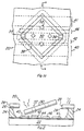
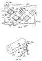
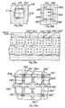
- a first preferred embodiment single pixel of a DMD fabricated by a first preferred embodiment method is illustrated in perspective view in Figure 1A, in cross sectional elevation in Figure 1B, and in plan view in Figure 1C.
- the pixel, generally denoted 20 is basically a beam (flap) covering a shallow well and includes silicon substrate 22, insulating spacer 24, metal hinge layer 26, metal beam layer 28, beam 30 formed in layers 26-28, and plasma etch access holes 32 in beam 30.
- the portions 34, 36 of hinge layer 26 that are not covered by beam layer 28 form torsion hinges (torsion rods) attaching beam 30 to the portion of layers 26-28 supported by spacer 24.
- Electrodes 40, 42, 46 and 41 run between spacer 24 and substrate 22 and are isolated from substrate 22 by silicon dioxide layer 44.
- Figure 1B is a cross section along line B-B as indicated in Figures 1A and 1C.
- Typical dimensions for pixel 20 would be as follows: beam 30 is a square with sides 12.5 microns long, spacer 24 is 4.0 microns thick (vertical in Figure 1B), hinge layer 26 is 800 ⁇ thick, beam layer 28 is 3,600 ⁇ thick, hinges 34 and 36 are each 4.6 microns long and 1.8 microns wide, plasma etch access holes 32 are 2.0 microns square, and plasma etch access gap 38 (the space between beam 30 and the remainder of beam layer 28) is 2.0 microns wide.
- beam 30 is a square with sides 19 microns long, spacer 24 is 2.3 microns thick (vertical in Figure 1B), hinge layer 26 is 750 ⁇ thick, beam layer 28 is 3,000 ⁇ thick, torsion hinges 34 and 36 are each 4.6 microns long and 1.0 microns wide, plasma etch access holes 32 are 1.5 microns square, and plasma etch access gap 38 (the space between beam 30 and the remainder of beam layer 28) is 1.0 micron wide.
- Substrate 22 is (100) silicon with resistivity about 10 ohm-cm and typically will have addressing circuitry formed on its surface, including peripheral devices in addition to electrodes 40, 41, 42, and 46.
- Spacer 24 is positive photoresist which is an insulator; hinge layer 26 and beam layer 28 are both an aluminum, titanium, and silicon alloy (Ti:Si:Al) with 0.2% Ti and 1% Si. This alloy has a coefficient of thermal expansion not drastically different from spacer 24 and thus minimizes the stress between the metal layers and spacer 24 generated during the fabrication process described in the following; also, the two layers 26 and 28 being the same metal minimizes stress. Note that any stress between layers in the beam or hinge would cause warping or curling of the beam or hinge, and any stress between the metal and the spacer can cause buckling or warping of the free portion of the metal over the well.
- Pixel 20 is operated by applying a voltage between metal layers 26-28 and electrodes 42 or 46 on substrate 22: beam 30 and the electrodes form the two plates of an air gap capacitor and the opposite charges induced on the two plates by the applied voltage exert electrostatic force attracting beam 30 to substrate 22, whereas electrodes 40 and 41 are held at the same voltage as beam 30.
- This attractive force causes beam 30 to twist at hinges 34 and 36 and be deflected towards substrate 22; see Figure 2 for a schematic view of this deflection together with an indication of the charges concentrated at the regions of smallest gap for a positive voltage applied to electrode 42.
- the deflection is in the range of 2 degrees.
- hinge 34 would increase as the compliance of hinge 34 varies linearly with the inverse of its width and directly with the square of its length and inversely with the cube of its thickness. Note that the thickness of beam 30 prevents significant warping of beam 30 due to surface stress generated during processing, but that the thinness of hinge 34 allows for large compliance.
- Figure 2 also indicates the reflection of light from deflected beam 30 as may occur during operation of a DMD.
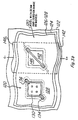
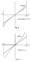
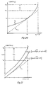
- FIG. 3A illustrates the approximate dependence of deflection on voltage for pixel 120 which is a simplified version of pixel 20 with electrodes 42 and 40 joined together as address electrode 142 (and electrodes 41 and 46 joined together as address electrode 146). See Figure 3B for a plan view with the elements of pixel 120 referenced numbered 100 higher than the corresponding elements of pixel 20.
- the voltage at which torsion beam 130 of pixel 120 becomes unstable and bends all the way to touch substrate 122 is called the collapse voltage.
- the deflection is approximately a linear function of the voltage (see the dotted line in Figure 3) and this is the analog operating region. Note that the voltages involved (40-50 volts) for analog operation are much larger than the usual for integrated circuits.
- Figure 4 is a schematic cross sectional elevation view (analogous to Figures 1B and 2) of pixel 120 showing definitions of the variables involved; and Figure 3B is a plan view to two adjacent pixels 120.
- address electrode 146 and torsion beam 130 are grounded and a voltage ⁇ a is applied to address electrode 142 which causes torsion beam 130 to rotate through an angle ⁇ .
- the rotation of the torsion beam may be expressed in terms of the distance that tip 131 of torsion beam 130 is deflected, z T , or as a distance ⁇ normalized to the distance between the undeflected torsion beam tip 131 and address electrode 142, z 0; that is For small angles of rotation and with ⁇ expressed in radians, ⁇ and ⁇ are related by where L is the length of the side of square torsion beam 130 which is torsion hinged at opposite corners 135 and 137.
- the torque exerted on torsion beam 130 about the axis through corners 135 and 137 by application of voltage ⁇ a to address electrode 142 is computed as follows. First consider the small (infinitesimal) area of torsion beam 130 located a distance x from the axis of rotation and of width dx (see the top view in Figure 4). The electrostatic energy in the small vertical volume between the small area on torsion beam 130 and address electrode 142 is approximately (assuming a uniform electric field ignoring fringing fields) equal to where is the electric field and is the electric displacement in the small vertical volume.
- z 0 - z is the height of the small vertical volume and that 2( L / ⁇ 2 - x ) is the length of the small area on torsion beam 130.
- the small force in the vertical ( z ) direction on the small area by the electric field is just the partial derivative of dU in the z direction: so and the small torque exerted on torsion beam 130 by this small force is just xdF z because the force has moment arm equal to x .
- Points of stable equilibrium for torsion beam 130 may be found by analyzing points of zero net torque.
- torsion beam tip 131 touches address electrode 142 and a large current passes through tip 131 to electrode 142 and tip 131 is welded to electrode 142. Therefore collapse is a destructive phenomenon for this particular architecture.
- the hinges act as fusible links and are blown away when the torsion beam collapses.
- Pixel 20 overcomes the problems of pixel 120 of high voltage operation ad destructive collapse of the torsion beam to the underlying electrodes.
- Pixel 20 has the addition of landing electrodes 40 and 41 which are electrically connected to torsion beam 30 and the connection of address electrode 42 with address electrode 46 but with a logical inversion of the address signal ⁇ a . See schematic Figure 7. The operation of pixel 20 is described in the following paragraphs.
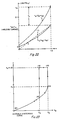
- the net attractive torque as a function of a is illustrated in Figure 8; the curves for ⁇ +( ⁇ ) and ⁇ ( ⁇ ) will be derived in a manner analogous to the derivation of ⁇ a in connection with the discussion of pixel 120.
- Figure 10 shows ⁇ a and ⁇ r for pixel 20 with small V B and grounded address electrodes 42 and 46.
- the opposite signs of ⁇ + and V B implies the attraction to address electrode 46 is greater than the attraction to address electrode 42 once the differential bias is applied even if beam 30 is still undeflected; also the small size of ⁇ means that prior to application of V B beam 30 need rotate only a small distance to reach a stable equilibrium point analogous to point "P" in Figure 5.
- applying the triggering potential ⁇ to address electrode 42 will rotate beam 30 to landing electrode 40 upon application of the differential bias.
- the triggering potential ⁇ ⁇ is of the same sign as V B , then this is approximately equivalent to applying a triggering potential of the opposite sign to the opposite address electrode once the differential bias is applied.
- ⁇ is just the ratio of the address voltage to the differential bias; and the smaller ⁇ can be made, the lower the voltage of operation of pixel 20.
- ⁇ 0.1 the net torque is zero at the point labelled "P", and for ⁇ > -
- a feature of the use of address electrodes with ⁇ ⁇ 1 in pixel 20 is the soft landing that beam 30 makes when it hits landing electrode 40 or 41 as compared to the landing that beam 130 of pixel 120 makes when it hits electrode 142 or 146 under similar operating conditions.
- Figure 20 illustrates the attracting and restoring torques for pixel 120 with the collapse voltage applied to address electrode 146 but with electrode 146 decreased in width to ⁇ times the half-width of beam 130 (this is the same ⁇ as in pixel 20 and is needed to avoid the unbounded nature of the attractive torque if beam 130 hits electrode 146).
- ⁇ can be chosen to make the collapse deflection ( ⁇ c ) approximately equal to 1, then ⁇ L , approaches zero.
- the first effect is the kinetic effect which deals with the mechanical damage produced by the impact of the moving beam hitting the electrode (either a landing electrode or the dielectric on an address electrode).
- the second effect is the static effect which deals with cold welding effects produced between the beam and the electrode caused by a sustained landing torque.
- the static effect is reduced by lowering the landing torque as has just been considered, and the kinetic effect is reduced by lowering the kinetic energy (speed) at landing.
- the kinetic energy at landing can be computed in two extreme cases, depending on the degree of mechanical damping. Damping is caused by the displacement of the air in the gap between the beam and the electrode as the beam quickly rotates ( ⁇ 1 ⁇ sec) to hit the electrode; and the two extreme cries are overdamping and no damping.
- the soft landing is effective in reducing both static and kinetic landing effects for pixel 120.
- the normalized landing torque can be experimentally determined by measuring the holding voltage V H as shown in Figure 22.
- ⁇ is fixed and V B is slowly decreased in magnitude below V 0.
- ⁇ a (1) has decreased in magnitude to ⁇ r (1), and the landing torque has decreased to zero.
- the net torque is in a direction to restore beam 30 to the analog equilibrium position labelled "P" in Figure 22. Therefore, as V B is slowly decreased and becomes slightly less than V H in magnitude, beam 30 suddenly releases from its landed position and returns to the much smaller deflected analog equilibrium.
- pixel 20 in the bistable mode can thus be described in terms of a hystersis curve as in Figure 23 which is a graph of a as a function of differential bias V B for a fixed ⁇ .
- pixel 20 operating in the bistable mode will not switch into proper stable states if certain pixel parameters deviate from the intended operating point by more than a specified amount.
- the amount of allowed deviation is called the noise margin; if any pixel parameter varies by more than the noise margin, then the pixel will switch into the wrong state.
- any noise or deviation of one parameter from the intended operating point reduces the noise margin of the other parameters for the pixel.
- the two most significant pixel 20 parameter deviations that can lead to faulty bistable operation are (i) torsion beam 30 deviation from flatness and (ii) address electrode 42 and 46 misalignment with respect to torsion hinges 34 and 36 and beam 30.
- ⁇ the margin for beam 30 deviation from flatness
- beam 30 has a built-in initial deflection of -
- is the maximum tolerable deviation from beam flatness and is called the margin for angular deviation.
- FIG. 25 One type of address electrode 42 and 46 misalignment with respect to beam 30 and torsion hinges 34 and 36 is illustrated in plan view in Figure 25; namely, the electrodes are misaligned along the diagonal by a distance ⁇ in the direction of landing electrode 40 and away from landing electrode 41 but all other alignments are correct. For simplicity, only this misalignment will be analyzed.
- Address electrode misalignment can also be compensated for by use of balance electrodes as illustrated schematically in cross sectional elevation view of preferred embodiment pixel 220 in Figure 27.
- Pixel 220 has address electrodes 242 ad 246, landing electrodes 240 and 241, plus balance electrodes 243 and 245 interposed between the address electrodes and the landing electrodes. If there is no misalignment, then the balance electrodes would be biased at the differential bias voltage; whereas, if there is misalignment of the address electrodes in the direction of landing electrode 240 (as in the previous discussion), then balance electrode would be biased towards ground to supply additional torque (increase ⁇ +) to counteract the misalignment. If the misalignment is in the other direction, then balance electrode 243 is biased towards ground.
- the margin for angular deviation ⁇ m is shown for both the aligned and misaligned cases, and clearly the misaligned case has a margin for angular deviation of one half of the aligned case margin with respect to the + electrode and a 50% greater margin with respect to the - electrode.
- the argument is symmetric and nonflatness within the angular deviation margin will lower the misalignment margin. Increase of ⁇ will expand the margins.
- the first method uses address electrode 42 as a reset electrode and address electrode 46 for addressing; pixel 20 is operated in the monostable or tristable mode and with rotation in one direction (to landing electrode 41) only.
- the reset method includes a high voltage pulse (90 volts for 1 ⁇ sec) applied to reset electrode 42 during the time that both the differential bias and the addressing voltage are at ground. See Figure 29 for a timing diagram which shows the differential bias ⁇ B applied to beam 30 and landing electrodes 40 and 41, the reset pulses ⁇ R applied to electrode 42 during times that ⁇ B vanishes, the addressing voltage ⁇ A for a sequence of deflect, not deflect, deflect applied to electrode 46, and the resultant beam deflection ⁇ . If beam 30 were stuck on landing electrode 41, then the pulse on reset electrode 42 provides a short duration torque to help the restoring torque of torsion hinges 34 and 36 pull beam 30 off of landing electrode 41.
- a high voltage pulse 90 volts for 1 ⁇ sec
- a second reset method is illustrated in Figures 30A-B and uses a nonrotational bending of torsion hinges 34 and 36 to help pull a stuck beam 30 off of landing electrodes 40 or 41.
- the reset pulse is applied to the landing electrodes 40 and 41 and beam 30 while address electrodes 42 and 46 are grounded.
- a differential bias bus may be used to connect together all of the landing electrodes and this bus is connected to the reflecting layer 26-28 which includes the torsion beams 30, so the reset pulse would just be applied to the differential bias bus.
- pixel 20 may be operated in any mode.
- the reset pulse (typically 60 volts for 1 ⁇ sec) applied to beam 30 with the address electrodes grounded deflects beam 30 towards substrate 22 whether beam 30 is undeflected or stuck to one of the landing electrodes; the nonrotational bending of torsion hinges 34 and 36 stores the potential energy of this deflection. See Figure 30A for a timing diagram and Figure 30B for illustration of the deflection.
- the beam and landing electrode bias ⁇ B has a reset pulse (+
- the addressing voltages ( ⁇ A (+) for electrode 46 and ⁇ A (-) for electrode 42) are for a sequence of deflections of beam 30 first to landing electrode 41, then landing electrode 40, and lastly back to landing electrode 41. At the end of the reset pulse this stored potential energy is released and provides an impulse pulling beam 30 straight up.
- Figure 31 is a plan view of a portion of a linear array 310 of second preferred embodiment pixels 320, 320', 320'', ... with each of the pixels similar to pixel 20.
- the beam 330, torsion hinges 334 and 336, landing electrodes 340 and 341, and address electrodes 342 and 346 are shown; similarly for pixel 320'. Note that the landing electrodes all connect to a central metal line 343.
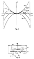
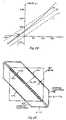
- Linear array 310 could be used for electrophotographic printing as illustrated schematically in Figures 32A-C.
- Figure 32A is a perspective view and Figures 32B-C are elevation and plan views showing system 350 which includes light source and optics 352, array 310, imaging lens 354, and photoconductive drum 356; the light from source 352 is in the form of a sheet 358 and illuminates linear array 310 with the light reflected from the area between beams 330, 330', 330'', ... forming sheet 360, the light reflected from negatively deflects beams within sheet 361, and the light reflected from positively deflected beams passing through imaging lens 354 within sheet 362 and focussed on drum 356 within line 364 as a series of dots, one for each deflected beam.
- system 350 which includes light source and optics 352, array 310, imaging lens 354, and photoconductive drum 356; the light from source 352 is in the form of a sheet 358 and illuminates linear array 310 with the light reflected from the area between beams 330, 330', 330'', ... forming sheet 360, the light reflected from negatively deflect
- linear array 310 is actually two rows of pixels, the image on drum 356 are dots within two lines and electronic delay of addressing one of the rows of pixels together with the drum rotation bring the image dots back into one line 364.
- a page of text or a frame of graphics information which has been digitized and is in raster-scanned format can be printed by feeding the information a line at a time to array 310 to form dots a line 364 at a time on drum 356 as drum 356 rotates; these dot images are transferred to paper by standard techniques such as xerography.
- ⁇ is the deflection angle of beam 330 when on landing electrodes 341, then sheet 362 is normal to linear array 310 when the angle of incidence of sheet 358 is 2 ⁇ from the normal to linear array 310.
- This geometry is illustrated in Figure 32B and permits imaging lens 354 to be oriented normal to linear array 310.
- Each positively deflected beam produces an image 355 of light source 352 on imaging lens 354 as schematically shown in Figure 32C for three beams.
- Linear array 310 with the pixels operating in bistable mode has advantages over linear arrays of cantilever beam pixels because (i) the bistable pixel operates at a larger deflection angle, so the angular subtense of the light source can be increased to yield a brighter dot at the drum; (ii) the turn-off pixels have the torsion beams deflected in the opposite direction rather than just undeflected as in the cantilever case, this doubles the reflection angle from turned-off pixels and lessens the optical contrast degradation due to beam curvature and eliminates the influence of anguar deviation for zero applied voltage; and (iii) brightness uniformity is improved because the deflection angle is a linear function of the spacer thickness and not dependent upon a non-linear region of operation where the deflection uniformity is very sensitive to spacer thickness and hinge compliance as with the cantilever beam.
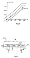
- Figure 33 is a cross sectional view of a single pixel 420 along address electrode 446 showing an input and enable gate 450
- Figure 34 is a plan view showing peels 420 and 420' and addressing circuitry.
- Ti:Si:Al electrode 446 is insulated from p type silicon substrate 422 by silicon dioxide 444, and the voltage to deflect beam 430 is applied to electrode 446, with metal layers 426-428 a common bias for all pixels and substrate 422 grounded.
- the landing electrodes 441 and 440 (shared as landing electrode 441' in pixel 420') are connected to metal layers 426-428 and thus beam 430.
- Enable gate 450 is polysilicon and insulated from substrate 422 by gate oxide 454, and n + doped regions 452, 456, 452', 456', ... and 462, 466, 462', 466', ... form the drains and sources, respectively, for MOSFETs with enable gate 450 as a common gate.
- Inputs for address electrodes 442 and 446 are applied to the MOSFET drains 452 and 456 and connected to the address electrodes when the MOSFETs are turned on by enable gate 450.
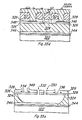
- Figure 38 illustrates in plan view a portion of linear array 510 of third preferred embodiment pixels including pixels 520, 520', 520''.
- Beams 530, 530', 530'' are octagonal with plasma etch access holes 532, 532', 532'' and plasma etch access gaps 538, 538', 538'', respectively; note that plasma etch access gaps 538 and 538' have a common portion between beams 530 and 530', as do the other gaps between abutting pixels.
- the wells in spacer 524 beneath beams 530, 530', 530'', ... all connect together and form one long well as indicated by the dotted lines in Figure 38.
- the address electrodes 542, 546, 542', 546', ... and landing electrodes 540, 541, 540', 541', ... are shown in Figure 38 by dashed lines; note that abutting landing electrodes are shared, for example, 541 and 540'.
- torsion hinges 534, 536, ... were shown as made from the same layer as beams 530, 530', 530'', ... .
- Figures 39A-D illustrate in plan views alternative beam geometries.
- Figure 39A shows a cantilever beam 570 with cantilever hinge 572, plasma etch access hole 574, plasma etch access gap 576, address electrode 578, and landing electrode 579.
- a cantilever beam only deflects in one direction and has torque curves similar to the curves of Figure 5 but bounded, so only monostable and bistable (one stable deflection point plus collapsed to lauding electrode 579) operation is available.
- Figure 39B shows torsion beam 580 with torsion hinges 581 and 582, plasma etch access holes 584, plasma etch access gap 586, address electrode 588, and landing electrode 589.
- Beam 580 deflects in only one direction and has operation similar to beam 570.
- Figure 39C shows a linear array of cantilever beams 590, 590', 590'', ... arranged as abutting inverted cloverleaves of groups of four beams.
- the wells under beams 590, 590', 590'', ... join to form a single elongated well as indicated by the dotted lines.
- Cantilever hinges 592, 592', 592'', ... are shown as made of the same layer as the beams and the address and landing electrodes are not shown for clarity.
- Figure 39D illustrates a portion of an area array of cantilever beams 560, 560', 560'', ... grouped in fours and supported on posts 561, 561', 561'', ... by cantilever hinges 562, 562', 562'', ... .
- Landing electrodes for the beams may be connected in rows such as electrode 563, and the beams are connected through the conductive posts to row electrodes 564.
- the address electrodes 565, 565', 565'', ... are addressed through circuitry not shown and fabricated in layers beneath the electrodes. Some of the electrodes are omitted for clarity.
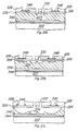
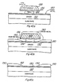
- a second preferred embodiment buried hinge fabrication method is shown in cross section ( Figure 40A-E) and in plan ( Figures 41A-C) views for a hinge located on a flat side of a torsion beam rather that at a corner.
- the cross section is taken in a transverse direction to the axis of the hinge (Section AA in Figure 41C).
- the second preferred embodiment process relies on metal liftoff to define the thin hinge metal region, rather than a buried SiO2 etch stop.
- only one plasma etch is required to etch both the hinge and beam metalization layers.
- the process begins with a sputter deposition of thin aluminum hinge layer 180 over spacer 182 (Figure 40A).
- a trilayer resist process is used to delineate what will later become the thin metal region into which the hinge pattern is finally etched.
- the trilayer resist process chosen is a modification of the Sestertious process of Y. C. Lin, et al, J. Vac. Sci. Technol., B1(4), 1215 (1983).
- the modified Sestertious process begins by spinning a spacer layer 184 of PMMA onto hinge metal 180.
- the thickness (approximately 5000 ⁇ ) is chosen to be slightly greater than the thickness of the beam metal.
- PMMA 184 is baked at a reduced temperature compared to the standard process in order to maintain a reasonably high solubility rate in its developer during the subsequent undercut of the photoresist capping layer.
- an antireflection coating (ARC) 186 is spun onto PMMA 184 and baked.
- ARC 186 coating serves to prevent an interfacial layer from forming between photoresist 188 and PMMA 184. It also reduces the amount of reflected light from hinge metal 180 during the subsequent photolithography exposure.
- ARC 186 is then coated with a positive photoresist 188.
- Photoresist 188 is exposed and developed in the desired hinge liftoff pattern and finally deep UV hardened and baked.
- ARC 180 is developed at the same time as photoresist 188.
- PMMA 184 is deep UV flood exposed so that regions of PMMA 184 not coated with photoresist 188 are reduced in their average molecular weight and become more soluble in chlorobenzene.
- a chlorobenzene develop of PMMA 184 quickly dissolves the exposed portion of PMMA 184 and an over-develop produces approximately a one micron undercut of the photoresist capping layer as shown in Figure 40A.
- An ash serves to remove filaments of softened PMMA which are thrown out during the spin dry following PMMA 184 develop.
- a hardbake then reduces the volatile components still contained in photoresist 188 and PMMA 184. These volatile components are caused by chlorobenzene absorption during the PMMA develop.
- beam metal 190 is sputter deposited.
- the overhanging photoresist cap on PMMA 184 causes sputtered beam metal 190 to break into two layers as shown in Figure 40B.
- Beam metal 190 is then lifted off by soaking and dissolving the trilayer resist pattern in either chlorobenzene or 1-methyl-2-pyrrolidinone.
- the result shown in cross sectional elevation view in Figure 40C and in plan view in Figure 41A) is a thin metal region 180 surrounded by a thick metal region 190, with thick metal 190 being tapered at its patterned edge 192.
- FIG. 40D cross sectional elevation
- Figure 41B plane view
- the opening in the photoresist is denoted 194 in the Figures
- the exposed metal is only hinge metal 180 for the two short horizontal portions of opening 194 in Figure 41B and beam metal 190 elsewhere.
- this pattern contains both the hinge and beam geometries, unlike the first preferred embodiment process. For this reason, the second preferred embodiment process is self-aligned.
- the exposed portion of hinge metal 180 and beam metal 190 is then plasma etched to simultaneously form both the hinge and beam geometries. After the photoresist has been ashed away the process is complete and the beam appears as in Figure 40E (cross section) and Figure 41C (plan view).
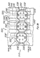
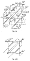
- FIG 42A is a plan view of a portion of array 610 of fourth preferred embodiment pixels 620, each pixel 620 includes torsion beam 630 supported by torsion hinges 634 and 636 which are in turn connected to posts 624, 624', 624'', ... ; the addressing circuitry for array 610 is not shown in Figure 42A but the overall addressing for the array is schematically illustrated in Figure 42B.
- Each pixel is represented as two variable capacitors (one for each address electrode) and two MOSFETs controlling access to the capacitors; the MOSFET gates are common for all pixels in a row, and the MOSFET drains are common for all pixels in a column.
- Array 610 is line addressed; that is, data is fed to the array one row of pixels at a time by the gate decoder selecting the wordline (gates) and the data is applied on the bitlines (drains) which then charge the floating sources and appropriately deflect the beams.
- the data may be entered in serial format and then converted to parallel format by a serial-to-parallel converter ("S/P Converter”) and held in a storage register (“Register”) until applied to the bitlines; the gate decoder sequentially selects the rows of the array.
- S/P Converter serial-to-parallel converter
- Register storage register
- Figures 43A-D are plan views illustrating successive levels in a pixel
- Figures 44A-C are cross sectional elevation views along lines A-A, B-B, and C-C in Figures 42A and 43A-D.
- Figure 43A shows n + diffused regions 660, 661, 662, 666, 660', ... and p + channel stops 670, 672, 670', ... in p ⁇ silicon substrate 622.
- Diffused lines 660 and 661 are bitlines and the drains for the MOSFETs
- regions 662 and 666 are the floating sources for the MOSFETs in pixel 620.
- Figure 43B is the gate level and shows polysilicon wordlines 680 and 680' with attached gates 682, 686, 682', 686', ... .
- Figure 43C illustrates the electrode level with only the wordlines and gates and floating sources indicated for clarity. Address electrodes 642 and 646 vertically connected to floating sources 662 and 666 through vias 663 and 667, respectively; whereas, landing electrodes 640 and 641 are shared with abutting pixels and interconnected through the beams and hinges in the reflecting layer.
- Figure 43D is the spacer level and shows that metal posts 624, 624', 624'', ... have taken the place of spacer 24 in pixel 20 to support reflecting layers 626 and 628 in which beams 630, 630', 630'', ... are formed.
- Metal posts 624, 624', 624'', ... electrically connect beams 630, 630', 630'', ... to landing electrodes 642, 646, ... in contrast to pixel 20 in which the spacer 24 insulates the beams from both the address and landing electrodes.
- Figure 42A is the reflecting layer level plan dew.
- Figures 44A-C are cross sectional elevation views of pixel 620 along lines A-A, B-B and C-C of Figure 42A and illustrate posts 624, 624', 624'', ... supporting the reflecting layer (hinge metal 626 plus beam metal 628) and which are fabricated from the hinge and beam metal depositions.
- Insulating silicon dioxide (oxide) 644 is about 8,000 ⁇ thick but has been reflowed to slope the sidewalls of the openings down to floating sources 662, 666, 662', ... to help the step coverage during deposition of the metal electrodes 642, 646, 642', ...
- Gate oxide 643 is about 800 ⁇ thick and preserved during the etching of deposited polysilicon to form wordlines and gates 682, 686, 682', ... .
- Array 610 may be fabricated by a method analogous to the first and second preferred embodiment methods described except the spacer layer (324 of the first method and 182 of the second method) is patterned to form openings for posts 624, 624', 624'', ... prior to deposition of hinge and beam metal. Then the deposition of hinge and beam metal forms the posts, and the spacer is totally etched away about the pixels.
- the circuitry beneath the electrodes is fabricated by standard silicon processing.
- the effectively symmetric beams may use differential bias.
- the address electrodes could be moved outside of the landing electrodes although this would require a more careful analysis of the attractive torque than that presented because the fringing fields would be the basis for the attraction.
- the dimensions and shapes can be varied such as the hinge length, width, and thickness (even hinges made of beam metal), the size of the beams and their thickness, the thickness of the spacer, and so forth. Even the geometry of the beams and hinges can be varied as shown in Figure 39.
- patterns of thick and thin portions could be fabricated in the beams, and three or more layers of metal with etch stops in each layer could yield various beam structures.
- the materials can be varied such as Cu:Al, Ti:W, chromium, etc. for the metal, differing resists or insulators such as polyimide for the spacer or composite spacers including conductive sublayers, radiation hardening of the spacer, other semiconductors for the substrate and the electrodes or metal electrodes, and so forth.
- the buried hinge etch stop could be a different material, such as tungsten; and processing could result in no etch stop remnants between the hinge metal and the beam metal.
- the landing electrodes could be covered with a thin layer of silicon dioxide or other material to prevent the sticking of the beams on the landing electrodes; or the landing electrodes could be made of a material different from the beams and thereby deter cold welding of the beam to the landing electrode; or the landing electrodes could be contoured to contact the beam away from the beam tip or edge.
- Various addressing circuitry may be formed beneath the electrodes, including vias to the backside of a substrate.
- the advantages of the landing electrode include the uniform, large-angle and soft-landed deflection of the beams.
Claims (10)
- Modulateur spatial de lumière formé dans une structure en couches ; ladite structure en couches comportant un substrat ou une couche de base (22, 322, 422, 622) , une couche centrale (24, 324, 424, 524, 624) sur ladite couche de base (22, 322, 422, 622) et une couche réflectrice (26, 28; 326, 328 ; 426, 428 ; 626, 628) de pixels (20, 220, 320, 420, 520, 620) , chacun desdits pixels (20, 220, 320, 420, 520, 620) comprenant :
un élément réflecteur de lumière, capable électrostatiquement de déviation (30,230,330, 430, 530, 630) formé dans ladite couche réflectrice (26,28 ; 326, 328; 426, 428; 626,628) et connecté au reste de ladite couche réflectrice (26, 28; 326,328; 426,428; 626, 628) par au moins une articulation (34,36; 334,336; 434, 436; 534, 536; 634,636) formée à partir de ladite couche réflectrice (26, 28; 326,328; 426,428; 626,628), ledit élément (30,230,330,430,530,630) étant maintenu à un premier potentiel de tension,
un puits formé dans ladite couche centrale (24, 324, 424, 524, 624) et s'étendant à partir dudit élément capable de déviation (30, 230, 330, 430, 530, 630) vers ladite couche de base (22, 322, 422, 622) de largeur supérieure à la largeur dudit élément capable de déviation (30, 230, 330, 430, 530, 630),
au moins une électrode d'adresse (42, 46 ; 242, 246; 342, 346 ; 442, 446; 542,546 ; 642,646) sur ladite couche de base (22, 322, 422, 622) au fond dudit puits entre ladite couche centrale (24, 324, 424,524, 624) et ladite couche de base (22, 322, 422, 622) et s'étendant au-dessous dudit élément capable de déviation (30, 230, 330, 430, 530, 630) et localisée pour dévier électrostatiquement ledit élément capable de déviation (30, 230, 330, 430, 530, 630) de telle sorte que lorsqu'une différence de potentiel est appliquée entre ledit élément capable de déviation (30, 230, 330, 430, 530, 630) et ladite électrode d'adresse (42, 46; 242, 246;342, 346;442, 446; 542,546; 642,646), ledit élément capable de déviation (30, 230, 330, 430, 530, 630) dévie, caractérisé par
au moins une électrode de contact (40, 41; 240, 241; 340,341; 440,441; 540, 541; 640, 641) sensiblement au même potentiel que ledit élément capable de déviation (30, 230, 330, 430, 530, 630) située sur ladite couche de base (22, 322, 422, 622) au fond dudit puits, placée pour être en contact avec ledit élément capable de déviation (30, 230, 330, 430, 530, 630) lorsque ledit élément capable de déviation (30, 230, 330, 430, 530, 630) est dévié électrostatiquement vers ladite au moins une électrode d'adresse (42, 46; 242, 246; 342, 346; 442, 446; 542,546; 642, 646). - Modulateur spatial de lumière selon la revendication 1 dans lequel ladite couche centrale (24, 324, 424, 524, 624) comprend, de plus, un polymère qui a été sélectivement enlevé pour former lesdits puits.
- Modulateur spatial pour lumière selon la revendication 1 ou la revendication 2 dans lequel ladite couche centrale comprend, de plus, une pluralité de bornes (624),lesdits puits étant formés entre lesdites bornes (624).
- Modulateur spatial de lumière selon l'une quelconque des revendications précédentes , dans lequel :
chacun desdits éléments capables de déviation (30, 230, 330, 430, 530, 630) est connecté à ladite couche réflectrice (26, 28; 326, 328; 426, 428; 626, 628)
par deux articulations à torsion (34, 36; 334, 336; 434, 436; 534, 536; 634, 636) ; et
chacun desdits pixels (20,220, 320, 420, 520, 620) comporte deux électrodes d'adresse (42, 46; 242, 246; 342, 346; 442, 446; 542, 546; 642, 646) et deux électrodes de contact (40, 41; 240, 241; 340, 341; 440, 441; 540, 541; 640, 641) . - Modulateur spatial de lumière selon la revendication 4 dans lequel lesdites deux électrodes d'adresse (42, 46; 242, 246; 342, 346; 442, 446; 542, 546; 642, 646) de chaque pixel (20, 220, 320, 420, 520, 620) sont espacées l'une de l'autre sur des côtés opposés de la ligne centrale de l'élément capable de déviation (30, 230, 330, 430, 530, 630) dans lequel ladite ligne centrale est une ligne imagnaire entre lesdites articulations (34,36; 334,336; 434,436; 534, 536; 634,636).
- Modulateur spatial de lumière selon la revendication 4 ou la revendication 5, dans lequel lesdites deux électrodes de contact (40,41; 240, 241; 340,341; 440, 441; 540, 541; 640, 641) sont espacées l'une de l'autre sur des côtés opposés de la ligne centrale de l'élément capable de déviation (30, 230, 330, 430, 530, 630) dans lequel ladite ligne centrale est une ligne imaginaire entre lesdites articulations (34, 36; 334, 336; 434, 436; 534,536;634,636).
- Modulateur spatial de lumière selon l'une quelconque des revendications précédentes, dans lequel :
ladite couche réflectrice (26,28; 326,328; 426, 428; 626, 628) est constituée d'une première (26, 326, 426, 626) et d'une seconde (28, 328, 428, 628) sous-couches, chacune desdites sous-couches (26,326, 426, 626 ; 28, 328, 428, 628) étant réalisée en métal; et
ladite au moins une articulation (34, 36; 334, 336; 434, 436; 534, 536; 634, 636) est formée seulement de ladite première sous-couche (26, 326, 426, 626). - Modulateur spatial de lumière selon l'une quelconque des revendications précédentes , dans lequel :
ledit puits dans ladite couche centrale (624) pour ledit pixel (620) rejoint le puits correspondant d'un pixel attenant (620). - Procédé de réinitialisation des pixels (20, 220, 320, 420, 520, 620) d'un modulateur spatial de lumière selon la revendication 5, dans lequel lesdits éléments capables de déviation (30, 230, 330, 430, 530, 630) sont déviés vers la première desdites deux électrodes d'adresse (42, 46; 242, 246; 342, 346; 442, 446; 542, 546; 642,646) par application d'une tension de signal à la seconde desdites deux électodes d'adresse (42,46; 242, 246; 342, 346; 442, 446; 542, 546; 642, 646) .
- Procédé d'adressage des pixels (20,220,320,420,520,620) d'un modulateur spatial de lumière selon l'une quelconque des revendications précédentes,caractérisé par les étapes consistant à :
appliquer des tensions de signaux aux électrodes d'adresse (42, 46; 242, 246; 342, 346; 442, 446; 542, 546; 642, 646) au-dessous de chaque élément capable de déviation (30, 230,330, 430, 530,630) ; et ensuite
appliquer directement une tension de polarisation auxdits éléments capables de déviation(30,230,330, 430, 530,630) entrainant lesdits éléments capables de déviation (30, 230, 330, 430, 530, 630) à répondre aux tensions des signaux appliquées précédemment sur lesdites électrodes d'adresse (42, 46; 242, 246; 342, 346; 442, 446; 542, 546; 642,646).
Applications Claiming Priority (2)
| Application Number | Priority Date | Filing Date | Title |
|---|---|---|---|
| US16872488A | 1988-03-16 | 1988-03-16 | |
| US168724 | 1988-03-16 |
Publications (3)
| Publication Number | Publication Date |
|---|---|
| EP0332953A2 EP0332953A2 (fr) | 1989-09-20 |
| EP0332953A3 EP0332953A3 (en) | 1989-11-23 |
| EP0332953B1 true EP0332953B1 (fr) | 1993-09-15 |
Family
ID=22612685
Family Applications (1)
| Application Number | Title | Priority Date | Filing Date |
|---|---|---|---|
| EP89103761A Expired - Lifetime EP0332953B1 (fr) | 1988-03-16 | 1989-03-03 | Modulateur spatial pour lumière et méthode |
Country Status (5)
| Country | Link |
|---|---|
| EP (1) | EP0332953B1 (fr) |
| JP (4) | JPH0782155B2 (fr) |
| KR (1) | KR0140756B1 (fr) |
| CN (2) | CN1025455C (fr) |
| DE (1) | DE68909075T2 (fr) |
Cited By (2)
| Publication number | Priority date | Publication date | Assignee | Title |
|---|---|---|---|---|
| US7952787B2 (en) | 2006-06-30 | 2011-05-31 | Qualcomm Mems Technologies, Inc. | Method of manufacturing MEMS devices providing air gap control |
| US8817357B2 (en) | 2010-04-09 | 2014-08-26 | Qualcomm Mems Technologies, Inc. | Mechanical layer and methods of forming the same |
Families Citing this family (48)
| Publication number | Priority date | Publication date | Assignee | Title |
|---|---|---|---|---|
| DE69019055T2 (de) * | 1989-02-27 | 1995-12-07 | Texas Instruments Inc | Apparat für ein digitalisiertes Videosystem. |
| EP0417523B1 (fr) * | 1989-09-15 | 1996-05-29 | Texas Instruments Incorporated | Modulateur de lumière et procédé |
| US4954789A (en) * | 1989-09-28 | 1990-09-04 | Texas Instruments Incorporated | Spatial light modulator |
| EP0460890A3 (en) * | 1990-06-06 | 1992-11-25 | Texas Instruments Incorporated | Optical tracking system |
| US5291473A (en) * | 1990-06-06 | 1994-03-01 | Texas Instruments Incorporated | Optical storage media light beam positioning system |
| EP0467048B1 (fr) * | 1990-06-29 | 1995-09-20 | Texas Instruments Incorporated | Dispositif à mirroir déformable avec mise à jour de trame |
| US5142405A (en) * | 1990-06-29 | 1992-08-25 | Texas Instruments Incorporated | Bistable dmd addressing circuit and method |
| US5083857A (en) * | 1990-06-29 | 1992-01-28 | Texas Instruments Incorporated | Multi-level deformable mirror device |
| US5148157A (en) * | 1990-09-28 | 1992-09-15 | Texas Instruments Incorporated | Spatial light modulator with full complex light modulation capability |
| US5151718A (en) * | 1990-12-31 | 1992-09-29 | Texas Instruments Incorporated | System and method for solid state illumination for dmd devices |
| US5170283A (en) * | 1991-07-24 | 1992-12-08 | Northrop Corporation | Silicon spatial light modulator |
| US5504514A (en) * | 1992-02-13 | 1996-04-02 | Texas Instruments Incorporated | System and method for solid state illumination for spatial light modulators |
| US5489952A (en) * | 1993-07-14 | 1996-02-06 | Texas Instruments Incorporated | Method and device for multi-format television |
| US5658698A (en) * | 1994-01-31 | 1997-08-19 | Canon Kabushiki Kaisha | Microstructure, process for manufacturing thereof and devices incorporating the same |
| US5444566A (en) * | 1994-03-07 | 1995-08-22 | Texas Instruments Incorporated | Optimized electronic operation of digital micromirror devices |
| CA2149952A1 (fr) * | 1994-06-30 | 1995-12-31 | Robert M. Wallace | Enduit monomoleculaire compose par reconnaissance moleculaire, pour dispositifs micromecaniques |
| US5490009A (en) | 1994-10-31 | 1996-02-06 | Texas Instruments Incorporated | Enhanced resolution for digital micro-mirror displays |
| JP3182301B2 (ja) * | 1994-11-07 | 2001-07-03 | キヤノン株式会社 | マイクロ構造体及びその形成法 |
| US5687130A (en) | 1994-11-30 | 1997-11-11 | Texas Instruments Incorporated | Memory cell with single bit line read back |
| US5610624A (en) | 1994-11-30 | 1997-03-11 | Texas Instruments Incorporated | Spatial light modulator with reduced possibility of an on state defect |
| US5648730A (en) | 1994-11-30 | 1997-07-15 | Texas Instruments Incorporated | Large integrated circuit with modular probe structures |
| US5999306A (en) | 1995-12-01 | 1999-12-07 | Seiko Epson Corporation | Method of manufacturing spatial light modulator and electronic device employing it |
| JP3576677B2 (ja) * | 1996-01-19 | 2004-10-13 | キヤノン株式会社 | 静電アクチュエータ及び、該アクチュエータを用いたプローブ、走査型プローブ顕微鏡、加工装置、記録再生装置 |
| TW357271B (en) * | 1996-02-26 | 1999-05-01 | Seiko Epson Corp | Light regulator, display and the electronic machine |
| JPH11149050A (ja) * | 1997-11-15 | 1999-06-02 | Canon Inc | 光偏向装置 |
| JP3402253B2 (ja) * | 1999-05-14 | 2003-05-06 | 日本電気株式会社 | 光変調素子及びそれを用いた光源と表示装置ならびにその駆動方法 |
| DE19941363B4 (de) * | 1999-08-31 | 2006-06-08 | Fraunhofer-Gesellschaft zur Förderung der angewandten Forschung e.V. | Verfahren zur Herstellung eines Mikroaktorbauteils |
| US6632557B1 (en) | 1999-10-26 | 2003-10-14 | The Gillette Company | Cathodes for metal air electrochemical cells |
| US6695457B2 (en) * | 2001-06-02 | 2004-02-24 | Capella Photonics, Inc. | Bulk silicon mirrors with hinges underneath |
| JP4520074B2 (ja) * | 2001-06-05 | 2010-08-04 | 富士通株式会社 | マイクロミラー駆動装置及びそのオフセット電圧調整方法 |
| JP2003005101A (ja) | 2001-06-26 | 2003-01-08 | Seiko Epson Corp | 光変調装置及びその製造方法 |
| JP4207666B2 (ja) * | 2002-05-28 | 2009-01-14 | ソニー株式会社 | 静電気機械素子、光回折変調素子、及び画像表示装置 |
| JP2004294756A (ja) * | 2003-03-27 | 2004-10-21 | Tdk Corp | 空間光変調器及びホログラム記録再生装置 |
| US6866887B1 (en) * | 2003-10-14 | 2005-03-15 | Photon Dynamics, Inc. | Method for manufacturing PDLC-based electro-optic modulator using spin coating |
| US7092599B2 (en) * | 2003-11-12 | 2006-08-15 | Engana Pty Ltd | Wavelength manipulation system and method |
| JPWO2005085929A1 (ja) * | 2004-03-09 | 2008-01-24 | 富士通株式会社 | ミラーデバイス,光制御装置,ミラーの制御方法およびミラー素子 |
| US7476327B2 (en) * | 2004-05-04 | 2009-01-13 | Idc, Llc | Method of manufacture for microelectromechanical devices |
| KR100707185B1 (ko) * | 2005-03-16 | 2007-04-13 | 삼성전자주식회사 | 복층 플레이트 구조의 액츄에이터 |
| JP2007015067A (ja) * | 2005-07-08 | 2007-01-25 | Fujifilm Holdings Corp | 微小薄膜可動素子及び微小薄膜可動素子アレイ並びに画像形成装置 |
| US20070046917A1 (en) * | 2005-08-31 | 2007-03-01 | Asml Netherlands B.V. | Lithographic apparatus and device manufacturing method that compensates for reticle induced CDU |
| WO2007140731A1 (fr) | 2006-06-03 | 2007-12-13 | Fraunhofer-Gesellschaft zur Förderung der angewandten Forschung e.V. | Dispositif d'électrodes pour éléments micromécaniques mobiles |
| US9134527B2 (en) | 2011-04-04 | 2015-09-15 | Qualcomm Mems Technologies, Inc. | Pixel via and methods of forming the same |
| US8963159B2 (en) | 2011-04-04 | 2015-02-24 | Qualcomm Mems Technologies, Inc. | Pixel via and methods of forming the same |
| JP6757123B2 (ja) * | 2015-04-30 | 2020-09-16 | 株式会社リコー | 光機能膜の製造方法、空間光変調素子の製造方法、光機能膜及び空間光変調素子 |
| CN206489310U (zh) * | 2016-09-30 | 2017-09-12 | 扬明光学股份有限公司 | 光路调整机构 |
| US10831018B2 (en) * | 2017-12-08 | 2020-11-10 | Texas Instruments Incorporated | Methods and apparatus for increasing efficiency and optical bandwidth of a microelectromechanical system piston-mode spatial light modulator |
| WO2021181618A1 (fr) * | 2020-03-12 | 2021-09-16 | 三菱電機株式会社 | Dispositif de balayage optique, dispositif de mesure de distance et procédé de fabrication de dispositif de balayage optique |
| CN114660717B (zh) * | 2022-04-01 | 2022-11-08 | 长沙思木锐信息技术有限公司 | 片上空间光调制器、散射聚焦系统及光调制方法 |
Family Cites Families (7)
| Publication number | Priority date | Publication date | Assignee | Title |
|---|---|---|---|---|
| US3886310A (en) * | 1973-08-22 | 1975-05-27 | Westinghouse Electric Corp | Electrostatically deflectable light valve with improved diffraction properties |
| US4229732A (en) * | 1978-12-11 | 1980-10-21 | International Business Machines Corporation | Micromechanical display logic and array |
| US4317611A (en) * | 1980-05-19 | 1982-03-02 | International Business Machines Corporation | Optical ray deflection apparatus |
| US4356730A (en) * | 1981-01-08 | 1982-11-02 | International Business Machines Corporation | Electrostatically deformographic switches |
| US4566935A (en) * | 1984-07-31 | 1986-01-28 | Texas Instruments Incorporated | Spatial light modulator and method |
| US4662746A (en) * | 1985-10-30 | 1987-05-05 | Texas Instruments Incorporated | Spatial light modulator and method |
| JPS6235322A (ja) * | 1985-08-09 | 1987-02-16 | Canon Inc | 光回路装置 |
-
1989
- 1989-03-03 EP EP89103761A patent/EP0332953B1/fr not_active Expired - Lifetime
- 1989-03-03 DE DE89103761T patent/DE68909075T2/de not_active Expired - Lifetime
- 1989-03-15 KR KR1019890003198A patent/KR0140756B1/ko not_active IP Right Cessation
- 1989-03-16 CN CN89101512A patent/CN1025455C/zh not_active Expired - Lifetime
- 1989-03-16 JP JP1064897A patent/JPH0782155B2/ja not_active Expired - Lifetime
-
1991
- 1991-05-31 JP JP3128049A patent/JP2546553B2/ja not_active Expired - Lifetime
- 1991-05-31 JP JP3128047A patent/JPH04230722A/ja active Pending
- 1991-05-31 JP JP3128048A patent/JPH0820616B2/ja not_active Expired - Fee Related
-
1993
- 1993-11-19 CN CN93114495A patent/CN1039061C/zh not_active Expired - Lifetime
Cited By (4)
| Publication number | Priority date | Publication date | Assignee | Title |
|---|---|---|---|---|
| US7952787B2 (en) | 2006-06-30 | 2011-05-31 | Qualcomm Mems Technologies, Inc. | Method of manufacturing MEMS devices providing air gap control |
| US8102590B2 (en) | 2006-06-30 | 2012-01-24 | Qualcomm Mems Technologies, Inc. | Method of manufacturing MEMS devices providing air gap control |
| US8964280B2 (en) | 2006-06-30 | 2015-02-24 | Qualcomm Mems Technologies, Inc. | Method of manufacturing MEMS devices providing air gap control |
| US8817357B2 (en) | 2010-04-09 | 2014-08-26 | Qualcomm Mems Technologies, Inc. | Mechanical layer and methods of forming the same |
Also Published As
| Publication number | Publication date |
|---|---|
| KR890015058A (ko) | 1989-10-28 |
| CN1038706A (zh) | 1990-01-10 |
| DE68909075T2 (de) | 1994-04-07 |
| CN1095485A (zh) | 1994-11-23 |
| EP0332953A3 (en) | 1989-11-23 |
| CN1039061C (zh) | 1998-07-08 |
| DE68909075D1 (de) | 1993-10-21 |
| JPH0782155B2 (ja) | 1995-09-06 |
| JP2546553B2 (ja) | 1996-10-23 |
| JPH04230722A (ja) | 1992-08-19 |
| JPH0820616B2 (ja) | 1996-03-04 |
| JPH028812A (ja) | 1990-01-12 |
| CN1025455C (zh) | 1994-07-13 |
| JPH04230723A (ja) | 1992-08-19 |
| EP0332953A2 (fr) | 1989-09-20 |
| JPH04230724A (ja) | 1992-08-19 |
| KR0140756B1 (ko) | 1998-08-17 |
Similar Documents
| Publication | Publication Date | Title |
|---|---|---|
| EP0332953B1 (fr) | Modulateur spatial pour lumière et méthode | |
| US5061049A (en) | Spatial light modulator and method | |
| EP0417523B1 (fr) | Modulateur de lumière et procédé | |
| US5096279A (en) | Spatial light modulator and method | |
| US5172262A (en) | Spatial light modulator and method | |
| US4662746A (en) | Spatial light modulator and method | |
| US4566935A (en) | Spatial light modulator and method | |
| US4956619A (en) | Spatial light modulator | |
| JP2571878B2 (ja) | 像作成装置 | |
| US4710732A (en) | Spatial light modulator and method | |
| US4615595A (en) | Frame addressed spatial light modulator | |
| US4954789A (en) | Spatial light modulator | |
| US5028939A (en) | Spatial light modulator system | |
| US7252395B2 (en) | MEMS device deflection stop | |
| KR100416679B1 (ko) | 공간광변조기 | |
| KR100284016B1 (ko) | 쌍안정 변형가능 미러 디바이스의 어드레싱 방법 | |
| EP0664470A2 (fr) | Dispositif de micro-miroir digitale à plusieurs niveaux | |
| JPH0756531B2 (ja) | 空間光変調器とその製法 |
Legal Events
| Date | Code | Title | Description |
|---|---|---|---|
| PUAI | Public reference made under article 153(3) epc to a published international application that has entered the european phase |
Free format text: ORIGINAL CODE: 0009012 |
|
| AK | Designated contracting states |
Kind code of ref document: A2 Designated state(s): DE FR GB IT NL |
|
| PUAL | Search report despatched |
Free format text: ORIGINAL CODE: 0009013 |
|
| AK | Designated contracting states |
Kind code of ref document: A3 Designated state(s): DE FR GB IT NL |
|
| 17P | Request for examination filed |
Effective date: 19900326 |
|
| 17Q | First examination report despatched |
Effective date: 19920605 |
|
| GRAA | (expected) grant |
Free format text: ORIGINAL CODE: 0009210 |
|
| AK | Designated contracting states |
Kind code of ref document: B1 Designated state(s): DE FR GB IT NL |
|
| PG25 | Lapsed in a contracting state [announced via postgrant information from national office to epo] |
Ref country code: IT Free format text: LAPSE BECAUSE OF FAILURE TO SUBMIT A TRANSLATION OF THE DESCRIPTION OR TO PAY THE FEE WITHIN THE PRESCRIBED TIME-LIMIT;WARNING: LAPSES OF ITALIAN PATENTS WITH EFFECTIVE DATE BEFORE 2007 MAY HAVE OCCURRED AT ANY TIME BEFORE 2007. THE CORRECT EFFECTIVE DATE MAY BE DIFFERENT FROM THE ONE RECORDED. Effective date: 19930915 |
|
| REF | Corresponds to: |
Ref document number: 68909075 Country of ref document: DE Date of ref document: 19931021 |
|
| ET | Fr: translation filed | ||
| PLBE | No opposition filed within time limit |
Free format text: ORIGINAL CODE: 0009261 |
|
| STAA | Information on the status of an ep patent application or granted ep patent |
Free format text: STATUS: NO OPPOSITION FILED WITHIN TIME LIMIT |
|
| 26N | No opposition filed | ||
| REG | Reference to a national code |
Ref country code: GB Ref legal event code: IF02 |
|
| PGFP | Annual fee paid to national office [announced via postgrant information from national office to epo] |
Ref country code: NL Payment date: 20080219 Year of fee payment: 20 Ref country code: GB Payment date: 20080211 Year of fee payment: 20 |
|
| PGFP | Annual fee paid to national office [announced via postgrant information from national office to epo] |
Ref country code: FR Payment date: 20080307 Year of fee payment: 20 Ref country code: DE Payment date: 20080331 Year of fee payment: 20 |
|
| REG | Reference to a national code |
Ref country code: GB Ref legal event code: PE20 Expiry date: 20090302 |
|
| NLV7 | Nl: ceased due to reaching the maximum lifetime of a patent |
Effective date: 20090303 |
|
| PG25 | Lapsed in a contracting state [announced via postgrant information from national office to epo] |
Ref country code: NL Free format text: LAPSE BECAUSE OF EXPIRATION OF PROTECTION Effective date: 20090303 |
|
| PG25 | Lapsed in a contracting state [announced via postgrant information from national office to epo] |
Ref country code: GB Free format text: LAPSE BECAUSE OF EXPIRATION OF PROTECTION Effective date: 20090302 |