EP0295178A2 - System and method for communicating signals in a cased borehole having tubing - Google Patents
System and method for communicating signals in a cased borehole having tubing Download PDFInfo
- Publication number
- EP0295178A2 EP0295178A2 EP88401381A EP88401381A EP0295178A2 EP 0295178 A2 EP0295178 A2 EP 0295178A2 EP 88401381 A EP88401381 A EP 88401381A EP 88401381 A EP88401381 A EP 88401381A EP 0295178 A2 EP0295178 A2 EP 0295178A2
- Authority
- EP
- European Patent Office
- Prior art keywords
- downhole
- uphole
- subsystem
- tubing
- code
- Prior art date
- Legal status (The legal status is an assumption and is not a legal conclusion. Google has not performed a legal analysis and makes no representation as to the accuracy of the status listed.)
- Granted
Links
- 238000000034 method Methods 0.000 title claims abstract description 36
- 238000004891 communication Methods 0.000 claims abstract description 62
- 230000005540 biological transmission Effects 0.000 claims abstract description 60
- 239000012530 fluid Substances 0.000 claims abstract description 35
- 230000008878 coupling Effects 0.000 claims abstract description 15
- 238000010168 coupling process Methods 0.000 claims abstract description 15
- 238000005859 coupling reaction Methods 0.000 claims abstract description 15
- 238000012545 processing Methods 0.000 claims description 8
- 238000004804 winding Methods 0.000 claims description 7
- 230000001681 protective effect Effects 0.000 claims description 5
- 238000001914 filtration Methods 0.000 claims description 4
- 239000011810 insulating material Substances 0.000 claims description 2
- 238000001228 spectrum Methods 0.000 abstract description 20
- 230000008901 benefit Effects 0.000 abstract description 12
- 230000003044 adaptive effect Effects 0.000 abstract description 4
- 239000010779 crude oil Substances 0.000 abstract description 4
- -1 diesel Substances 0.000 abstract description 2
- 238000012360 testing method Methods 0.000 description 19
- 238000010586 diagram Methods 0.000 description 18
- 239000004020 conductor Substances 0.000 description 11
- 230000006870 function Effects 0.000 description 11
- 238000005259 measurement Methods 0.000 description 11
- 238000003860 storage Methods 0.000 description 10
- 230000000694 effects Effects 0.000 description 7
- 238000004519 manufacturing process Methods 0.000 description 7
- 230000004044 response Effects 0.000 description 7
- 230000000638 stimulation Effects 0.000 description 7
- 238000005553 drilling Methods 0.000 description 6
- 230000015572 biosynthetic process Effects 0.000 description 5
- 238000005755 formation reaction Methods 0.000 description 5
- 230000001012 protector Effects 0.000 description 5
- XEEYBQQBJWHFJM-UHFFFAOYSA-N Iron Chemical compound [Fe] XEEYBQQBJWHFJM-UHFFFAOYSA-N 0.000 description 4
- 229910003460 diamond Inorganic materials 0.000 description 4
- 239000010432 diamond Substances 0.000 description 4
- 239000002184 metal Substances 0.000 description 4
- 229910052751 metal Inorganic materials 0.000 description 4
- 230000035699 permeability Effects 0.000 description 4
- 238000005086 pumping Methods 0.000 description 4
- 238000004458 analytical method Methods 0.000 description 3
- 238000013461 design Methods 0.000 description 3
- 238000012544 monitoring process Methods 0.000 description 3
- 230000000737 periodic effect Effects 0.000 description 3
- 230000008569 process Effects 0.000 description 3
- 230000002829 reductive effect Effects 0.000 description 3
- 230000002441 reversible effect Effects 0.000 description 3
- 238000012546 transfer Methods 0.000 description 3
- 229910000831 Steel Inorganic materials 0.000 description 2
- 230000002238 attenuated effect Effects 0.000 description 2
- 239000012267 brine Substances 0.000 description 2
- 230000008859 change Effects 0.000 description 2
- 239000011248 coating agent Substances 0.000 description 2
- 238000000576 coating method Methods 0.000 description 2
- 230000006835 compression Effects 0.000 description 2
- 238000007906 compression Methods 0.000 description 2
- 230000005284 excitation Effects 0.000 description 2
- 239000012212 insulator Substances 0.000 description 2
- 229910052742 iron Inorganic materials 0.000 description 2
- 230000000670 limiting effect Effects 0.000 description 2
- 238000005070 sampling Methods 0.000 description 2
- 230000008054 signal transmission Effects 0.000 description 2
- HPALAKNZSZLMCH-UHFFFAOYSA-M sodium;chloride;hydrate Chemical compound O.[Na+].[Cl-] HPALAKNZSZLMCH-UHFFFAOYSA-M 0.000 description 2
- 239000010959 steel Substances 0.000 description 2
- 238000006842 Henry reaction Methods 0.000 description 1
- 230000004913 activation Effects 0.000 description 1
- 230000002411 adverse Effects 0.000 description 1
- 239000003570 air Substances 0.000 description 1
- 238000013459 approach Methods 0.000 description 1
- 238000005311 autocorrelation function Methods 0.000 description 1
- 230000006399 behavior Effects 0.000 description 1
- 230000002457 bidirectional effect Effects 0.000 description 1
- 238000009530 blood pressure measurement Methods 0.000 description 1
- 238000004364 calculation method Methods 0.000 description 1
- 239000004568 cement Substances 0.000 description 1
- 230000000295 complement effect Effects 0.000 description 1
- 230000001419 dependent effect Effects 0.000 description 1
- 238000011161 development Methods 0.000 description 1
- 239000002283 diesel fuel Substances 0.000 description 1
- 238000009826 distribution Methods 0.000 description 1
- 230000002500 effect on skin Effects 0.000 description 1
- 230000008030 elimination Effects 0.000 description 1
- 238000003379 elimination reaction Methods 0.000 description 1
- 230000002349 favourable effect Effects 0.000 description 1
- 230000014509 gene expression Effects 0.000 description 1
- 238000009499 grossing Methods 0.000 description 1
- 230000036039 immunity Effects 0.000 description 1
- 230000006872 improvement Effects 0.000 description 1
- 230000000977 initiatory effect Effects 0.000 description 1
- 238000003780 insertion Methods 0.000 description 1
- 230000037431 insertion Effects 0.000 description 1
- 230000002452 interceptive effect Effects 0.000 description 1
- 238000002955 isolation Methods 0.000 description 1
- 230000007246 mechanism Effects 0.000 description 1
- 230000004048 modification Effects 0.000 description 1
- 238000012986 modification Methods 0.000 description 1
- 239000003129 oil well Substances 0.000 description 1
- 230000010355 oscillation Effects 0.000 description 1
- 239000003208 petroleum Substances 0.000 description 1
- RGCLLPNLLBQHPF-HJWRWDBZSA-N phosphamidon Chemical compound CCN(CC)C(=O)C(\Cl)=C(/C)OP(=O)(OC)OC RGCLLPNLLBQHPF-HJWRWDBZSA-N 0.000 description 1
- 239000004033 plastic Substances 0.000 description 1
- 239000004065 semiconductor Substances 0.000 description 1
- 239000000243 solution Substances 0.000 description 1
- 230000003068 static effect Effects 0.000 description 1
- 238000004441 surface measurement Methods 0.000 description 1
- 230000001360 synchronised effect Effects 0.000 description 1
Images


Classifications
-
- E—FIXED CONSTRUCTIONS
- E21—EARTH DRILLING; MINING
- E21B—EARTH DRILLING, e.g. DEEP DRILLING; OBTAINING OIL, GAS, WATER, SOLUBLE OR MELTABLE MATERIALS OR A SLURRY OF MINERALS FROM WELLS
- E21B47/00—Survey of boreholes or wells
- E21B47/12—Means for transmitting measuring-signals or control signals from the well to the surface, or from the surface to the well, e.g. for logging while drilling
- E21B47/13—Means for transmitting measuring-signals or control signals from the well to the surface, or from the surface to the well, e.g. for logging while drilling by electromagnetic energy, e.g. radio frequency
-
- F—MECHANICAL ENGINEERING; LIGHTING; HEATING; WEAPONS; BLASTING
- F02—COMBUSTION ENGINES; HOT-GAS OR COMBUSTION-PRODUCT ENGINE PLANTS
- F02B—INTERNAL-COMBUSTION PISTON ENGINES; COMBUSTION ENGINES IN GENERAL
- F02B3/00—Engines characterised by air compression and subsequent fuel addition
- F02B3/06—Engines characterised by air compression and subsequent fuel addition with compression ignition
Definitions
- This invention relates to communications in an earth borehole and, more particularly, to a wireless telemetry system and method for communication in a cased borehole in which tubing is installed.
- the invention further relates to the communication of information in such a system, in close to real time, during perforation, testing, stimulation (such as fracturing) and production.
- the prior art describes a variety of wireless communications systems for measurement while drilling. Some of these are measurement-while-drilling systems that utilize the drill pipe and the formations (and/or metal casing, to the extent present) to transmit electromagnetic signals over a "transmission line" that includes the drill string as a central conductor, and the formations (and/or casing, as the case may be) as outer conductors.
- a toroidal antenna at the intermediate communications system launches a signal that is received by a toroidal antenna at the surface, the toroidal antenna surrounding a conductor that is connected between structure coupled to the drill string and the metal borehole casing.
- the wireless link can be utilized for two-way communication, and can also be used for sending power downhole for operation without a battery or for charging a battery.
- an important feature of the invention is to have the intermediate communication system away from the drill bit environment, and also indicates that the communication between the intermediate communication system and the surface is practical over only relatively short distances, for example, 1000 feet.
- the system and method of the present invention has particular application for use in an earth borehole which is cased with an electrically conductive casing and has electrically conductive tubing extending therethrough.
- a communication system for communicating between downhole and the earth's surface.
- a downhole communications subsystem is mounted on the tubing.
- the downhole subsystem includes a downhole antenna means for coupling electromagnetic energy in a TEM mode to and/or from the annulus between the casing and the tubing.
- the downhole subsystem further includes a downhole transmitter/receiver coupled to the downhole antenna means, for coupling signals to and/or from the antenna means.
- An uphole communications subsystem is located at the earth's surface, and includes uphole antenna means for coupling electromagnetic energy in a TEM mode to and/or from the annulus, and an uphole receiver/transmitter coupled to the uphole antenna means, for coupling the signals to and/or from the uphole antenna means.
- the annulus contains a substantially non-conductive fluid (such as diesel, crude oil, or air) in at least the region of the downhole antenna means and above.
- a packer is mounted on the tubing below the downhole communications subsystem, and is operative, inter alia, to prevent incursion of fluid into the annulus above the packer.
- An advantage of the communications link utilized in the present invention is that transmission losses can be kept relatively low (since the annulus between the tubing and the casing has been filled with a non-conductive fluid), so less power is needed for transmission of information. This tends to reduce the downhole power requirements and permits operation with less battery power, when a battery is employed downhole. Further, since the power needed for transmission of data is not unduly high, the data rates can be higher than they could be if conservation of power was a critical limiting factor. The relatively high efficiency of the transmission link also facilitates battery-less operation or operation with a rechargeable battery.
- the transmission link of the present invention also benefits from other features hereof, which are described in detail below. Briefly, a spread-spectrum coding scheme is employed, which is found to be particularly effective in accurately carrying information of the transmission link, even in the presence of conditions that cause substantial random interference. In an embodiment hereof, the coding scheme is adaptive to take account of changing conditions of the transmission path. In a further embodiment hereof, a demodulation technique is utilized at the receiver to improve performance of the communication system during times when periodic motion of the tubing might be encountered.
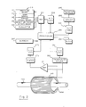
- FIG. 1 there is shown a simplified schematic diagram of a system in accordance with the invention and which can be used to practice the method of the invention.
- Earth formations 111 are traversed by a borehole that has been cased with a steel casing 115.
- the borehole has been equipped with steel tubing 130 that may be conventionally employed during or for perforation, stimulation, testing, treating, and/or production.
- tubing is intended to generically include an elongated electrically conductive metal structure having an internal passage which can pass fluid through most or all of its length, and having a periphery that is smaller, over most of its length, than the radius of the cased borehole in which it extends.
- the downhole apparatus 140 is mounted, in Fig. 1, on one of the lower sections of tubing, and above a packer 135.
- the downhole apparatus 140 is shown as being contained within a tool enclosure 141, and includes a downhole sensing and communications subsystem 145 and at least one antenna means which, in the illustrated embodiment, is a toroidal antenna 149.
- Protective collars, such as are shown at 102, are of an insulating material, and help prevent contact between the tubing and casing. These collars are spaced closer together at greater depths to prevent buckling under the higher forces encountered.
- An uphole apparatus 160 includes an uphole antenna means 161, which, in the present embodiment, comprises a transformer having one of its windings coupled across the casing 115 and the tubing 130 and the other of its windings coupled to a control and communications subsystem 165.
- electromagnetic energy in a transverse electromagnetic (“TEM") mode is launched in the annulus defined by the region 20 inside the casing and outside the tubing.
- a substantially non-conductive fluid for example diesel or crude oil or air, is put in the annulus, and serves as the non-conductive dielectric in the transmission line model. Without such fluid in place, transmissions over relatively long distances (more than a few hundred feet) will generally suffer high attenuation and be of limited use.
- the packer 135 serves, inter alia, to prevent incursion of conductive fluid from below the packer into the annulus of the transmission line.
- the uphole antenna means may alternatively be a toroid around the tubing 130, or any other suitable excitation and/or sensing means that excites and/or senses electromagnetic energy in a TEM mode which propagates in the annulus between the tubing and the casing.
- the downhole antenna means 149 may also be any suitable excitation and/or sensing means.
- the packer 135 is assumed to be electrically conductive, there is effectively a short at the bottom of the coaxial transmission line, and the toroidal antenna is an effective exciter and/or sensor.
- a conductive pin can be employed to ensure a short of tubing to casing below the downhole communications subsystem. [If there is no such short near the downhole antenna (e.g.
- the spacing between the casing and tubing is effectively an open circuit at the top of the transmission line, so signal can be efficiently sensed across the gap; e.g. with a high impedance voltage measurement or a lower impedance current measurement (that would close the open circuit).
- the current flow path in Fig. 1 can be visualized as follows: down from the lower surface of the insulated well head flange 131, through the casing 115 to the packer 135, across the packer 135 to the tubing 130, up through the downhole communication system 141 and tubing 130 to the surface, across the slips 189 (see Fig. 4), and then down again to the upper surface of the insulated flange.
- a rig isolator such as an insulating sleeve - not shown
- treating iron insulator such as an insulated section of treating iron - not shown
- FIG. 2 there is shown a block diagram of an embodiment of the downhole measuring and communications subsystem 141.
- the conditions that can be measured downhole are pressure, temperature, torque, weight on packer, and fluid flow. These measurements are taken using sensing units 210 individually designated as pressure gauge 211, temperature gauge 212, strain gauges 213 and 214, and flowmeter 215.
- the electrical outputs of these measuring devices are coupled, via an analog multiplexer 221, to analog-to-digital converter 226, the output of which is coupled to a processor 250.
- the processor 250 may be any suitable processor, for example an Intel 8088 microprocessor, having associated memory, input/output ports, etc. (not shown).
- the processor 250 has a precision clock 255 associated therewith.
- a pressure-activated wakeup counter (not shown) can be employed if desired, to cause activation from a low power mode, for example upon the onset of pumping.
- the processor 250 controls operation of the other downhole circuitry.
- the processor 250 generates information signals, to be described, which are coupled, via digital-to-analog converter 251, to a transformer driver 256.
- the output of transformer driver is coupled to toroidal antenna 149 which, in this embodiment, is a toroidal coil wound on a cylindrical core 149A.
- the antenna 149 is concentric with the tubing 130, and generates the electromagnetic energy in a TEM mode that propagates in the annulus between the tubing and casing.
- the toroid comprises one winding of a transformer in which the loop formed by the tubing, packer, casing etc. is the other winding.
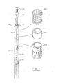
- Fig. 3 shows an embodiment of a downhole tool configuration.
- the downhole subsystem 140 is formed on and concentric with a section of the tubing (which, if desired or necessary, can have a slightly reduced inner diameter), and includes the coil 149, battery 260, circuit board(s) 205, on which can be mounted the downhole circuitry of Fig. 2 and suitable housing for sensors 210.
- a protective metal outer cover 142 which is open-ended to permit passage of the transmitted or received energy, is insulated from the tubing by a barrel insulator 143. It will be understood that various alternative configurations and arrangements of the subsystem components can be employed.
- FIG. 4 there is shown a diagram, partially in block form, of an embodiment of the uphole communications subsystem as utilized in the system of Fig. 1.
- one winding of transformer 161 is coupled between the tubing and the casing at flange 131.
- this coupling can be across a flange that is mounted on the casing, the upper surface of the flange 131 being insulated from the lower surface thereof by an insulating gasket ring 137.
- the other transformer winding is coupled, in a balanced configuration, to a preamplifier 410 and then to a low-pass filter 415.
- the output of filter 415 is coupled to an analog-to-digital converter 420, the output of which is coupled to processor 450.
- the processor may comprise any suitable computer or microprocessor, for example, having associated memory, input/output ports, etc. (not shown). For example, a Motorola 68000 processor may be employed.
- Uphole clock 425 is provided in conjunction with the processor 450. As described further herein below, this clock can be synchronized with the downhole clock.
- a terminal 490 and a recorder 495 are also provided.
- Fig.s 2 and 4 thus far have been mostly concerned with transmission of signals from downhole to uphole.
- the transmission link of the present invention is bidirectional, and circuitry can be provided in the uphole and downhole subsystems to implement transmission from uphole to downhole of control information and/or power.
- information from processor 450 is coupled to digital-to-analog converter 471, and then to transformer driver 472, to drive the transformer 161 when the uphole subsystem is operating in a transmission mode.
- the toroidal coil 149 is coupled to amplifier 271, anti-aliasing filter 272, analog-to-digital 273, and then processor 250, when the downhole subsystem is operating in a receiving mode.
- Suitable switching and isolation circuits can be provided, if necessary.
- a further output of processor 250 is illustrated as being coupled, via digital-to-analog converter 291 and driver 292, to downhole actuator devices 295.
- These devices may typically include valves and any other suitable types of devices for actuation from uphole and/or in accordance with a programmed downhole routine.
- the battery 260 is shown as providing power for the downhole circuitry.
- the transmission link of the present invention can also be used to transmit power from uphole to downhole, and the power can be utilized to run the downhole circuitry and/or to charge a rechargeable battery.
- a power supply circuit 520 which includes suitable rectification and smoothing circuitry, as represented by elements D1, C1 and L1, is coupled to the downhole antenna 149 via a semiconductor switch 510 (controlled by processor 250) and bandpass filter 515.
- an AC power source 490 is coupled to transformer 161 via switch 492, controlled by processor 450.
- the power signal can be sent during quiet periods of information signal transmission (in either the downhole or uphole signal directions), or the power signal can be sent simultaneously with transmission signals or with the information being transmitted to downhole being superimposed on the power signal. Regarding receipt of the power signal downhole, this can be done using the same receiving antenna as is used for the information signal, as previously illustrated. In Fig. 6, a separate receiver antenna 249 is illustrated as being provided for receiving the power signal. Another alternative is to provide separate antennas for transmitting and receiving, uphole and/or downhole.
- the annulus between the tubing and the casing is filled (at least, in the region of the transmission link) with a substantially non-conductive fluid, for example, diesel, crude oil, or air.
- a substantially non-conductive fluid is intended to mean a fluid having a conductivity of less than about 0.1 Siemens/meter, and it is preferred that the conductivity be less than about 10- 3 Siemens/meter.
- conventional completion practices provide a facility to circulate fluids from/to the annulus to/from the tubing; for example a flow control valve 105 in the tubing immediately above the packer 135 (see Fig. 1).
- the valve 105 can be controlled, for example, by rotating the tubing. Alternatively, this valve could be associated with the packer 135. Prior to treatment, the existing fluid can be circulated out and replaced, as desired, with the non-conductive fluid. After treatment (or at any other desired time), the insulating fluid can be circulated out with conventional fluid.
- a continuous monochromatic carrier wave is conceptually portioned into a contiguous sequence of single-cycle wavelets or "chips"; a fixed-length pseudorandom (plus- and minus-) sign sequence is then assigned to a contiguous set of chips, thus constituting one "on" bit of binary information.
- pseudorandom sign sequence By reversing the signs of the entire pseudorandom sign sequence, one "off" bit of binary information is created.
- each message sent over the telemetry system comprises 15 contiguous bits, with each bit being represented by 63 pseudorandom sign-coded chips.
- the code representing the two possible states of a bit are the reverse of each other at each chip.
- the pseudorandom code for an "on” bit is "1101000"
- the code for an "off” bit would be "0010111..”
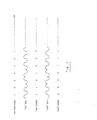
- Fig. 7 illustrates the seven "chips" at the beginning of this sequence, with the top waveform showing the beginning of the sequence (for this particular pseudorandom code) for an "on” bit, and the bottom waveform showing the reverse pattern, which is the beginning of the sequence for an "off” bit.
- a chip having a positive polarity portion followed by a negative polarity portion is designated as a "1” chip, whereas a chip having a negative polarity portion followed by a positive polarity portion is designated as a "0" chip.
- sampling theorem requires a sampling rate of twice the highest frequency expected in the incoming analog signal. This assures that digital signal processing techniques will function properly and that the continuous analog signal can be recovered at any processing step, if so desired. If basic system "carrier” frequency is 500 Hz it has negligible energy above 1000 Hz and thus can be adequately sampled at 2000 Hz.
- the basic "signal event”, as shown in Fig. 7, is not well localized in time. However, its broad, spread spectrum assures that, with the proper phase filtering, that signal event can be significantly compressed in time.
- the "optimal” filter normally chosen for effecting the time compression is the "matched” filter (see, e.g., "Signal Processing", M. Schwartz, McGraw Hill, 1975). By design, the matched filter optimizes the signal excursion at a single point in time in the presence of Gaussian random noise.
- m(t) is simply the time reverse of the signal event to which it is being applied, thus effectively replacing each signal event with its zero-phase autocorrelation function.
- m(t) s(-t), where s(t) is a coded signal event like that shown in Fig. 7.
- the matched filtering operation f(t) becomes
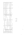
- Fig. 8 shows an example of the waveforms for a received message consisting of 15 bits of information at 500Hz.
- Fig. 9 illustrates the matched-filtered results obtained by autocorrelation. The 15 bits, and their polarities, are clearly visible as being "100001111101010".
- An additional technique which can be utilized to advantage in the present invention is to have a repertoire of pseudorandom codes for possible use, and to adaptively select the code to be used at a particular time in accordance with the transfer function associated with the transmission link, as measured just before the time in question, or during a similar condition (e.g. testing, stimulation, etc.). This can be done, for example, indirectly, by sending the repertoire of possible codes from downhole in a predetermined sequence, and performing autocorrelations at the surface using the same sequence of codes. The code providing the cleanest autocorrelated signal can then be used for sending subsequent data. The selection process can then be repeated after a particular period of time or after a change in conditions.
- a particular test code sequence can be sent, and the transfer function of the transmission link can be computed from the received signal.
- the computed transfer function can then be convolved, at the surface with each of the repertoire of codes, and the best result selected; whereupon a control signal would be sent downhole to select the particular code to be used for subsequent data transmission.
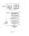
- Fig. 10 there is shown a flow diagram of the routine for the downhole processor. It will be understood that techniques for collection and transmission of data are known in the art, and those portions hereof which do not, per se, relate to the invention will be described in general terms, or understood as being in accordance with known principles.
- the block 1011 represents the control of multiplexer 221 (Fig. 2) to sample the outputs of the sensors 210 in accordance with either a predetermined routine or commands from uphole.
- the block 1012 represents the storage of the data downhole, and the loop 1020, including interrupt control and the block 1015, represents the continuous monitoring of sensor data. Sharing of attention from the processor can be in accordance with a predetermined priority basis, as is known in the art.
- the block 1031 represents the accessing of memory to obtain the appropriate stored information to be sent uphole.
- the selection of data to be transmitted can be in accordance with a predetermined routine or can be controlled from uphole.
- the data from a particular sensor or sensors may be transmitted simultaneously with its acquisition and storage, although typically the data rate associated with downhole storage will be higher than the transmission data rate, and storage from multiple sensors can be implemented without compromising the fastest available uphole transmission.
- the storage of critical data downhole may provide a backup, for later retrieval, in the event of a failure in the transmission link or system.
- the information retrieved from storage is compiled into a message, in accordance with the particular format being used (block 1032).
- the first data bit of the message to be transmitted is considered (block 1033), and the spread-spectrum code for the bit (i.e., the 63 chip code for a "1", or the complementary 63 chip code for a "0", as previously described) is fetched from memory, and transmitted, as represented by the blocks 1034 and 1035.
- the codes to be used can be stored, for example, in random access memory associated or in programmable read-only memory associated with the processor 250. Inquiry is made (diamond 1036) as to whether or not the last bit of the message has been transmitted. If not, the next bit is considered (block 1037), and the loop 1039 continues until the entire message has been transmitted.
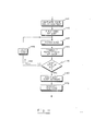
- the spread-spectrum code used can be modified, under control from the surface, after a test sequence during which a repertoire of the available spread-spectrum codes are transmitted to the surface. After selection, at the surface, of the particular spread-spectrum code which exhibits the best noise immunity, a control signal is sent from the surface to designate the spread-spectrum code to be utilized until the next test sequence.
- the routine is illustrated in Fig. 11, wherein the block 1141 represents initiation of the code selection test routine upon receipt of a command from the surface.
- the block 1142 is entered, this block representing the selection of the first code of the list for transmission.
- the block 1143 represents the fetching of the current code, and the block 1144 represents the transmission of a predetermined number of repetitions of the code.
- Inquiry is then made (diamond 1145) as to whether or not the last code of the list has been transmitted. If not, the code index is incremented (block 1146), the block 1143 is reentered, and the loop 1150 is continued until all codes have been sent. The command designating the best code is then awaited (block 1160), and when it is received, the new code is specified (block 1170). Until a new code is specified, communications between uphole and downhole, in either direction, would use the currently specified code. [The downhole routine for decoding messages from uphole can be the same as the one used uphole, and described herein below in conjunction with the routine of Fig. 12.]
- the downhole processor is further programmed to achieve further routine functions, such as sending synchronizing signals to synchronize the uphole clock, sending signals indicative of the status of downhole circuits, power, etc.
- the correlation process can performed using either analog or digital technique, and reference can be made to the above noted publications for details of the correlation process.
- the next sampled level is received and stored in a register (e.g., in RAM) at the next address, as represented by the blocks 1206 and 1207.
- the correlation window which is an overlay of the spread-spectrum code, is then moved to the next position (block 1211), the values at each chip position are multiplied, and the results over the window are added, to obtain a correlation value for the particular window position, these functions being represented by the block 1215.
- inquiry is made (diamond 1220) as to whether or not a predetermined number of correlation values have been stored. If not, block 1206 is reentered, further sample values are obtained, and further correlation values computed and stored (loop 1225). The pattern of peaks is then sought, as represented by the block 1241. Numerically, this would correspond to peaks having positive or negative values greater than a predetermined magnitude. The bit values ("1" or "0"), depending upon the polarities of the peaks, are then read out (block 1242), and the routine is repeated (loop 1250) in looking for the next bit.
- Fig. 13 illustrates the routine for the processor uphole in testing the repertoire or list of possible codes to be used, and selection of one of the particular codes for use during the subsequent time period or during a particular condition.
- the block 1371 represents the transmitting of the command to initiate the test.
- An index indicating the first test code pattern to be received is initiated, as represented by block 1372.
- Correlation is then performed over a predetermined number of cycles (block 1374); i.e., the predetermined number of cycles of the test pattern that are transmitted from downhole.
- a quality figure obtained for the correlation e.g. by determining the strength of the correlation peaks, together with absence of lost signals
- inquiry is made (diamond 1380) as to whether or not the last code of the list has been received.
- test code pattern index is incremented (block 1381), and the loop 1385 is continued until a quality figure is obtained for each code of the list.
- the code having the best performance is then selected (block 1391), and a command is sent downhole to use this selected code for subsequent transmission, as represented by the block 1392.
- tubing is subjected to mechanical forces that can result in contacts between the tubing and casing, which can be viewed as shorts in the transmission line.
- clamped-on tubing isolators are used to protect against such shorts.
- Rubber drill collar protectors could be used for this purpose, but plastic protectors would have the advantage of lower cost.
- the stresses to which tubing is subjected have been previously studied (see e.g. "Basic Fluid And Pressure Forces On Oilwell Tubulars", D.J. Hammerlindl, JPT, 1980; and “Helical Bucking Of Tubing Sealed In Packers", A. Lubinski, Petroleum Transactions, 1961). Compressive stresses that can cause buckling of the tubing are highest at the bottom of the well. Accordingly, the tubing protectors should preferably be spaced closer together as the bottom of the well is approached.
- Fig. 14 shows a schematic of the differential lumped circuit and sets forth model components of the system, as follows: the series resistance per unit length of the combined inner and outer conductors, R; the series self-inductance per unit length of the conductors, L; the shunt conductance per unit length afforded by the annular fluid, G; and the shunt capacitance per unit length between the conductors, C.
- Fig. 15 schematically shows the transmission line voltage and current locations and introduces the input impedance, Zi N , and a source resistance, R s .
- the input impedance is related to the line parameters and the load as follows: where L is the length of the transmission line.
- the respective load-to-source voltage and current ratios for Fig. 15 are and
- Fig. 16 schematically shows the insertion of a shorted section into the transmission line, such as one might expect where either a section of the tubing touches the casing or where a section of the annular fluid is highly conductive, the latter occurring, for example, if formation brine has leaked into the system.
- the above ratios (4) are calculated for each section and cascaded for the final ratios.
- V s (2) /V s (1) Z o (s) must be substituted for Z o and ⁇ (s) for y.
- the appropriate lengths ( L 1, LS and L 2) must be substituted for L.
- the power response resulting from an input voltage impulse is obtained from the dot product of the voltage and current at the load, viz., V L ⁇ IL.
- the subject transmission line can be analyzed to obtain expressions Tor R, L, G, and C as required by (4) tor the characteristic impedance Zo and propagation constant y.
- Fig. 17 in what follows, the assumption is made that the fluid inside the inner pipe and the outside environment, typically consisting of a thin inner coaxial cement layer and an outer layer of horizontally stratified earth, can be ignored (i.e., treated as empty space).
- the magnetic field exists primarily between the two conductors; and, due to the "skin effect", the current density will exponentially decay from the outer edge of the inner conductor and the inner edge of the outer conductor.
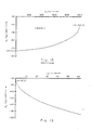
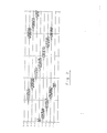
- Table 1 shows a typical tabular form of voltage and power ratios, obtained using the above relationships, for the coaxial system arrangement in a test well, for a 1500 m depth and diesel in the annulus. As can be seen, there is little signal voltage attenuation by the coaxial system. At 500 Hz, the signal voltage is attenuated by only -.5 dB, increasing to -1.3 dB at 1,900 Hz.
- Fig. 18 shows the effects of a point short of 1 milliohm at various positions along a 1000 m transmission line at 500 Hz.
- the Figure shows that a short near the transmitter, i.e., near the bottom of the well, has a much less severe attenuating effect on the signal voltage. Due to the distribution of stress along the tubing in normal operations, shorting is much more likely to happen nearer the bottom.
- Fig. 19 shows the effects of the same 1 milliohm short as it is distributed over various lengths of the coaxial system.
- a technique is employed for improving reception of communicated signals in the presence of a periodic short in the transmission link, such as would be expected to be created by harmonic motion of the tubing during high-volume pumping of fluid through the tubing. If the motion is severe enough to cause the tubing to contact the casing (i.e., assuming that the protective collars are not spaced sufficiently close together, or fail), the signal transmitted during such contact may be severely attenuated.
- a demodulation technique can be employed to advantage at the receiving subsystem (uphole or downhole, depending on which subsystem is receiving) in recovering the coded information at the receiving subsystem. [With regard to demodulation in communication systems in general, see “Signals, Systems and Communication", B.
- a full-wave rectifier technique is employed.
- the received signals are processed to obtain their absolute value, and then low-pass filtered with a high cut-off at or below the carrier frequency.
- This low-pass filtering is effected herein by taking a running average.
- Demodulation is then achieved by dividing the incoming signal by the derived modulating function. The result is similar to subjecting the signal to an automatic gain control which boosts the signals during the periods of attenuation.
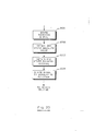
- FIG. 20 illustrates the routine for the processor in the receiving subsystem.
- Block 2021 represents storage of the received signals
- the block 2022 represents obtainment and storage of the absolute value of the received signals.
- a running average is then computed (block 2023), and constitutes the modulation function.
- the received signal (previously stored) is then divided by the modulating function, as represented by the block 2024.
- the decoding routine can then be implemented, as previously described.
- Fig.s 21-24 illustrate an example of the type of improvement that can be obtained using the demodulation technique.
- Fig. 21 illustrates an example of an otherwise clean received signal that has been modulated by electrical short circuit between the tubing and casing caused by tubing oscillations while pumping at ten barrels per minute. (Protective collars around the tubing were intentionally omitted during the test). The generally periodic drastic signal attenuation is seen to be very distinct, and has a frequency in about the 6-20 Hz range.
- Fig. 22 shows the results of decoding the received data of Fig. 21, and it is seen that while the correlation procedure still exhibits the bits, some are hardly discernible.
- Fig. 23 illustrates the received data after the described type of demodulation processing, and
- Fig. 24 shows the results of decoding after the demodulation processing. Signal-to-noise ratio for the 15 decoded bits was substantially improved.
- references to the surface of the earth may include the ocean surface, for example when the system is employed offshore.
- communication to a subsystem at ocean bottom may be useful, such as for communicating to or from valves, such as in a blowout protection mechanism.
Abstract
Description
- This invention relates to communications in an earth borehole and, more particularly, to a wireless telemetry system and method for communication in a cased borehole in which tubing is installed. The invention further relates to the communication of information in such a system, in close to real time, during perforation, testing, stimulation (such as fracturing) and production.
- During perforation, testing, stimulation, treating, and/or production of a well, it would be very advantageous to have accurate information concerning conditions downhole; particularly, conditions such as pressure, temperature, fluid flow rate, weight on a packer, etc. Techniques for utilizing information concerning these conditions have advanced in recent years. Accordingly, if suitable information concerning downhole conditions is available, the interpretation resulting therefrom can be used to make decisions that can greatly enhance the ultimate production and cost efficiency of the well. An example is the so-called Nolte-Smith technique for interpretation of fracturing pressures (see "Interpretation of Fracturing Pressures", Nolte et al., SPE, 1981), which is widely used in industry, and has intensified the desire for continuous bottom-hole pressure data. The importance of obtaining these data as they occur (in close to real time), for example for controlling a fracturing operation, is substantial (see, for example, "The Real-Time Calculation Of Accurate Bottomhole Fracturing Pressure From Surface Measurements", R.R. Hannah et al., SPE, 1983; "Prediction Of Formation Response From Fracture Pressure Behavior", M.W. Conway et al., SPE, 1985; "Computerized Field System For Real Time Monitoring And Analysis Of Hydraulic Fracturing Operations", M.P. Cleary et al., SPE, 1986). However, to Applicants' knowledge, there is no currently existing technique for obtaining measurements of downhole conditions that does not have significant drawbacks.
- Among the existing techniques for obtainment of data on downhole conditions with tubing in place, are the following:
- 1. Data can be taken with a measuring instrument downhole, and recovered after completion of the job. This has the obvious drawback of the unavailability of the data during the job, and limitations on downhole power and data collecting ability.
- 2. In a situation of a packerless completion, the bottom hole pressure can be estimated at the surface via measurement of the annular static fluid column. This provides only a low frequency filtered pressure measurement. Also, the casing is exposed to treating pressures.
- 3. Bottom-hole conditions can be approximated from conditions measured uphole, for example pressure, fluid properties, etc. However, the accuracy of these indirect measurements is generally poor. Among the reasons, is the close proximity to surface pumping noise.
- 4. Sensing devices can be placed downhole with an electrical cable strapped to the outside of tubing, or run inside the tubing, or can be lowered after the fact to connect downhole or to interrogate a downhole device. These techniques have obvious advantages in providing a good communications link. However, in addition to the cost of the cabling, the possibility of the cable tangling, interfering with mechanical structure and/or fluid flow, breaking, or not making suitable contact downhole, renders this technique less than ideal in many applications.
- The prior art describes a variety of wireless communications systems for measurement while drilling. Some of these are measurement-while-drilling systems that utilize the drill pipe and the formations (and/or metal casing, to the extent present) to transmit electromagnetic signals over a "transmission line" that includes the drill string as a central conductor, and the formations (and/or casing, as the case may be) as outer conductors.
- In the U.S. Patent No. 4,057,781 Scherbatskoy, there is disclosed a measurement and communications system for measurement while drilling which employs a cable for communication between sensing devices located near the drill bit and an intermediate communications system that is first mounted at the top of the drill string when a round-trip drill bit change is implemented. As drilling proceeds, drill pipes having an insulating coating painted thereon are added to the string, so that the intermediate communications system will eventually be a few hundred feet below the earth's surface. Rubber drill collar protectors are provided to prevent the drill pipe from rubbing against the casing. Communication between the intermediate communication system and a surface communication system is wireless. A toroidal antenna at the intermediate communications system launches a signal that is received by a toroidal antenna at the surface, the toroidal antenna surrounding a conductor that is connected between structure coupled to the drill string and the metal borehole casing. (Alternatively, the patent notes, potential between the drill string and the casing can be utilized.) The wireless link can be utilized for two-way communication, and can also be used for sending power downhole for operation without a battery or for charging a battery. The patent states that an important feature of the invention is to have the intermediate communication system away from the drill bit environment, and also indicates that the communication between the intermediate communication system and the surface is practical over only relatively short distances, for example, 1000 feet. Among the practical limitations of the apparatus described in this patent are the need for a cable between the intermediate communications and the system near the bottom of the hole, the need for providing an insulating coating on the upper portion of the drill string, and the limitations on the length of the wireless communication. Other measurement while drilling schemes, communication systems, and control systems, are described in the following U.S. Patent No.s: 2,225,668 2,354,887 2,400,170 2,414,719 2,492,794 2,653,220 2,940,039 2,989,621 2,992,325 3,090,031 3,315,22-4 3,408,561 3,495,209 3.732.728 3,737,845 3,793,632 3,831,138 3,967,201 4,001.773 4,087,781 4,160.970 4,215.4-25 4,215,426 4,215,427 4,226,578 4,302,757 4,348,672 4,387,372 4,496,174 4,525,715 4,534,424 and 4,578,675. Whereas a variety of wireless communication systems have been proposed for measurement while drilling, there has been a dearth of viable proposals for wireless communication in a cased borehole in which tubing is in place, and in which perforation, testing, stimulation, and/or production are typically to be implemented. The prospect of having wireless downhole communications in such a system, which can be used to communicate information in almost real time, and over relatively long periods of time, would appear to be a difficult objective. This is especially true if it is desired to have the system be operative to communicate with reasonable accuracy and data rate during operations which exacerbate the already hostile downhole conditions; for example, testing, stimulation, etc. These operations can involve severe pressure, temperature, and mechanical vibrations in the downhole environment and uncontrolled motion of the tubing.
- It is among the objects of the present invention to provide a wireless communication system and method for use in a cased borehole that has been equipped with tubing. It is among the further objects of the invention to provide such a communications system which can operate under adverse conditions, including conditions that severely perturb the transmission path for communication; which can provide two way wireless communication between the earth's surface and one or more downhole locations; which is capable of communicating power to a downhole location, where the power is converted to a form suitable for use in operating the downhole subsystem or for storage for later use for such purpose; and which employs a coding scheme that permits accurate transmission of data, and which can be adapted for changes in the characteristics of the transmission path during particular conditions.
- The system and method of the present invention has particular application for use in an earth borehole which is cased with an electrically conductive casing and has electrically conductive tubing extending therethrough. In accordance with the system of the invention, there is provided a communication system for communicating between downhole and the earth's surface. A downhole communications subsystem is mounted on the tubing. The downhole subsystem includes a downhole antenna means for coupling electromagnetic energy in a TEM mode to and/or from the annulus between the casing and the tubing. The downhole subsystem further includes a downhole transmitter/receiver coupled to the downhole antenna means, for coupling signals to and/or from the antenna means. An uphole communications subsystem is located at the earth's surface, and includes uphole antenna means for coupling electromagnetic energy in a TEM mode to and/or from the annulus, and an uphole receiver/transmitter coupled to the uphole antenna means, for coupling the signals to and/or from the uphole antenna means. In accordance with a feature of the invention, the annulus contains a substantially non-conductive fluid (such as diesel, crude oil, or air) in at least the region of the downhole antenna means and above. A packer is mounted on the tubing below the downhole communications subsystem, and is operative, inter alia, to prevent incursion of fluid into the annulus above the packer.
- An advantage of the communications link utilized in the present invention is that transmission losses can be kept relatively low (since the annulus between the tubing and the casing has been filled with a non-conductive fluid), so less power is needed for transmission of information. This tends to reduce the downhole power requirements and permits operation with less battery power, when a battery is employed downhole. Further, since the power needed for transmission of data is not unduly high, the data rates can be higher than they could be if conservation of power was a critical limiting factor. The relatively high efficiency of the transmission link also facilitates battery-less operation or operation with a rechargeable battery. This can be achieved by transmitting power downhole and using the received power downhole as a source for a downhole power supply that energizes the downhole equipment and/or charges a downhole rechargeable battery. Further benefits of lower power consumption include extended temperature application (where reduced battery power would normally be expected to be a limiting factor), and reduced mechanical cost and tool size, since the elimination of need for battery replacement and smaller batter size both lead to manufacturing advantages. Further, the invention has advantages for use in reservoir monitoring during the production phase of a well. The transmission link of the present invention also benefits from other features hereof, which are described in detail below. Briefly, a spread-spectrum coding scheme is employed, which is found to be particularly effective in accurately carrying information of the transmission link, even in the presence of conditions that cause substantial random interference. In an embodiment hereof, the coding scheme is adaptive to take account of changing conditions of the transmission path. In a further embodiment hereof, a demodulation technique is utilized at the receiver to improve performance of the communication system during times when periodic motion of the tubing might be encountered.
- Further features and advantages of the invention will become more readily apparent from the following detailed description when taken in conjunction with the accompanying drawings.
-
- Fig. 1 is a simplified schematic diagram, partially in block form, of a system in accordance with an embodiment of the invention, and which can be used to practice the method of the invention.
- Fig. 2 is block diagram, partially in schematic form, of the downhole measuring and communications subsystem.
- Fig. 3 illustrates a configuration of an embodiment of the downhole tool.
- Fig. 4 is a diagram, partially in block form, of an embodiment of the uphole communications subsystem.
- Fig. 5 illustrates a portion of an embodiment of the downhole subsystem, including a power supply driven by power transmitted from uphole.
- Fig. 6 is a diagram of a portion of an embodiment of the downhole subsystem utilizing two toroidal antennas.
- Fig. 7 illustrates a portion of a sequence of a pseudorandom code of the type utilized in an embodiment of the invention.
- Fig. 8 shows an example of waveforms for a received message consisting of 15 bits of information.
- Fig. 9 illustrates the matched-filtered results obtained by autocorrelation of the Fig. 8 waveforms.
- Fig. 10 is a flow diagram of a routine for programming of the downhole processor.
- Fig. 11 is another routine for programming the downhole processor for an adaptive code selection test sequence.
- Fig. 12 is a flow diagram of a routine for programming the uphole processor for decoding the spread-spectrum coded information sentfrom downhole.
- Fig. 13 is a flow diagram of another routine for the uphole processor, pertaining to the adaptive code modification.
- Fig. 14 is a schematic of a differential lumped circuit, setting forth model components of the system.
- Fig. 15 is a schematic diagram of a transmission line model.
- Fig. 16 is a schematic diagram of another transmission line model, with a shorted section.
- Fig. 17 is a schematic of parameterization of a coaxial pipe system, as seen from an end view.
- Fig. 18 shows the effects of a point short at various positions along a transmission line.
- Fig. 19 shows the effects of a short of various lengths.
- Fig. 20 is aflow diagram of a routine for demodulation in accordance with a feature of the invention.
- Fig. 21-24 illustrate a sequence of pseudorandom codes sent and received during a condition of shorting, and show the effects of using a demodulation technique at the receiver.
- Referring to Fig. 1, there is shown a simplified schematic diagram of a system in accordance with the invention and which can be used to practice the method of the invention. Earth formations 111 are traversed by a borehole that has been cased with a
steel casing 115. In this illustration, the borehole has been equipped withsteel tubing 130 that may be conventionally employed during or for perforation, stimulation, testing, treating, and/or production. As used herein, the term "tubing" is intended to generically include an elongated electrically conductive metal structure having an internal passage which can pass fluid through most or all of its length, and having a periphery that is smaller, over most of its length, than the radius of the cased borehole in which it extends. - The
downhole apparatus 140 is mounted, in Fig. 1, on one of the lower sections of tubing, and above apacker 135. Thedownhole apparatus 140 is shown as being contained within atool enclosure 141, and includes a downhole sensing andcommunications subsystem 145 and at least one antenna means which, in the illustrated embodiment, is atoroidal antenna 149. Protective collars, such as are shown at 102, are of an insulating material, and help prevent contact between the tubing and casing. These collars are spaced closer together at greater depths to prevent buckling under the higher forces encountered. Anuphole apparatus 160 includes an uphole antenna means 161, which, in the present embodiment, comprises a transformer having one of its windings coupled across thecasing 115 and thetubing 130 and the other of its windings coupled to a control andcommunications subsystem 165. - In the present invention, electromagnetic energy in a transverse electromagnetic ("TEM") mode is launched in the annulus defined by the
region 20 inside the casing and outside the tubing. A substantially non-conductive fluid, for example diesel or crude oil or air, is put in the annulus, and serves as the non-conductive dielectric in the transmission line model. Without such fluid in place, transmissions over relatively long distances (more than a few hundred feet) will generally suffer high attenuation and be of limited use. Thepacker 135 serves, inter alia, to prevent incursion of conductive fluid from below the packer into the annulus of the transmission line. - The uphole antenna means may alternatively be a toroid around the
tubing 130, or any other suitable excitation and/or sensing means that excites and/or senses electromagnetic energy in a TEM mode which propagates in the annulus between the tubing and the casing. The downhole antenna means 149 may also be any suitable excitation and/or sensing means. In the present embodiment, wherein thepacker 135 is assumed to be electrically conductive, there is effectively a short at the bottom of the coaxial transmission line, and the toroidal antenna is an effective exciter and/or sensor. If necessary or desired, a conductive pin can be employed to ensure a short of tubing to casing below the downhole communications subsystem. [If there is no such short near the downhole antenna (e.g. an insulating packer or no packer), or the downhole antenna is positioned a considerable distance (comparable to a quarter wavelength) above such short, a signal impressed between the tubing and casing or a gap in either the tubing or casing, may be desirable.] At the earth's surface, the spacing between the casing and tubing (at an insulating flange 131) is effectively an open circuit at the top of the transmission line, so signal can be efficiently sensed across the gap; e.g. with a high impedance voltage measurement or a lower impedance current measurement (that would close the open circuit). - From the standpoint of current flow, the current flow path in Fig. 1 can be visualized as follows: down from the lower surface of the insulated
well head flange 131, through thecasing 115 to thepacker 135, across thepacker 135 to thetubing 130, up through thedownhole communication system 141 andtubing 130 to the surface, across the slips 189 (see Fig. 4), and then down again to the upper surface of the insulated flange. To prevent interference, a rig isolator (such as an insulating sleeve - not shown) and treating iron insulator (such as an insulated section of treating iron - not shown) can be provided. - Referring to Fig. 2, there is shown a block diagram of an embodiment of the downhole measuring and
communications subsystem 141. In the illustration of Fig. 2, the conditions that can be measured downhole are pressure, temperature, torque, weight on packer, and fluid flow. These measurements are taken usingsensing units 210 individually designated aspressure gauge 211,temperature gauge 212,strain gauges flowmeter 215. The electrical outputs of these measuring devices are coupled, via ananalog multiplexer 221, to analog-to-digital converter 226, the output of which is coupled to aprocessor 250. Theprocessor 250 may be any suitable processor, for example an Intel 8088 microprocessor, having associated memory, input/output ports, etc. (not shown). Theprocessor 250 has aprecision clock 255 associated therewith. A pressure-activated wakeup counter (not shown) can be employed if desired, to cause activation from a low power mode, for example upon the onset of pumping. Theprocessor 250 controls operation of the other downhole circuitry. - The
processor 250 generates information signals, to be described, which are coupled, via digital-to-analog converter 251, to atransformer driver 256. The output of transformer driver is coupled totoroidal antenna 149 which, in this embodiment, is a toroidal coil wound on acylindrical core 149A. Theantenna 149 is concentric with thetubing 130, and generates the electromagnetic energy in a TEM mode that propagates in the annulus between the tubing and casing. Another way of viewing the generation of the transmitted energy is that the toroid comprises one winding of a transformer in which the loop formed by the tubing, packer, casing etc. is the other winding. - Fig. 3 shows an embodiment of a downhole tool configuration. In the illustration, the
downhole subsystem 140 is formed on and concentric with a section of the tubing (which, if desired or necessary, can have a slightly reduced inner diameter), and includes thecoil 149,battery 260, circuit board(s) 205, on which can be mounted the downhole circuitry of Fig. 2 and suitable housing forsensors 210. A protective metalouter cover 142, which is open-ended to permit passage of the transmitted or received energy, is insulated from the tubing by abarrel insulator 143. It will be understood that various alternative configurations and arrangements of the subsystem components can be employed. - Referring to Fig. 4, there is shown a diagram, partially in block form, of an embodiment of the uphole communications subsystem as utilized in the system of Fig. 1. As first shown in Fig. 1, one winding of
transformer 161 is coupled between the tubing and the casing atflange 131. As seen further in Fig. 4, this coupling can be across a flange that is mounted on the casing, the upper surface of theflange 131 being insulated from the lower surface thereof by an insulatinggasket ring 137. The other transformer winding is coupled, in a balanced configuration, to apreamplifier 410 and then to a low-pass filter 415. The output offilter 415 is coupled to an analog-to-digital converter 420, the output of which is coupled toprocessor 450. The processor may comprise any suitable computer or microprocessor, for example, having associated memory, input/output ports, etc. (not shown). For example, a Motorola 68000 processor may be employed.Uphole clock 425 is provided in conjunction with theprocessor 450. As described further herein below, this clock can be synchronized with the downhole clock. A terminal 490 and arecorder 495 are also provided. - The descriptions of Fig.s 2 and 4 thus far have been mostly concerned with transmission of signals from downhole to uphole. However, the transmission link of the present invention is bidirectional, and circuitry can be provided in the uphole and downhole subsystems to implement transmission from uphole to downhole of control information and/or power. In Fig. 4, information from
processor 450 is coupled to digital-to-analog converter 471, and then totransformer driver 472, to drive thetransformer 161 when the uphole subsystem is operating in a transmission mode. In Fig. 2, thetoroidal coil 149 is coupled toamplifier 271,anti-aliasing filter 272, analog-to-digital 273, and thenprocessor 250, when the downhole subsystem is operating in a receiving mode. Suitable switching and isolation circuits (not shown) can be provided, if necessary. In the diagram of Fig. 2, a further output ofprocessor 250 is illustrated as being coupled, via digital-to-analog converter 291 anddriver 292, todownhole actuator devices 295. These devices may typically include valves and any other suitable types of devices for actuation from uphole and/or in accordance with a programmed downhole routine. - In the embodiment of Fig. 2, the
battery 260 is shown as providing power for the downhole circuitry. The transmission link of the present invention can also be used to transmit power from uphole to downhole, and the power can be utilized to run the downhole circuitry and/or to charge a rechargeable battery. For example, as shown in Fig. 5, apower supply circuit 520, which includes suitable rectification and smoothing circuitry, as represented by elements D1, C1 and L1, is coupled to thedownhole antenna 149 via a semiconductor switch 510 (controlled by processor 250) and bandpass filter 515. In the uphole subsystem, anAC power source 490 is coupled totransformer 161 viaswitch 492, controlled byprocessor 450. There are a number of options with regard to the transmission of the power and its receipt downhole. If desired, the power signal can be sent during quiet periods of information signal transmission (in either the downhole or uphole signal directions), or the power signal can be sent simultaneously with transmission signals or with the information being transmitted to downhole being superimposed on the power signal. Regarding receipt of the power signal downhole, this can be done using the same receiving antenna as is used for the information signal, as previously illustrated. In Fig. 6, aseparate receiver antenna 249 is illustrated as being provided for receiving the power signal. Another alternative is to provide separate antennas for transmitting and receiving, uphole and/or downhole. - In accordance with a feature of the invention, the annulus between the tubing and the casing is filled (at least, in the region of the transmission link) with a substantially non-conductive fluid, for example, diesel, crude oil, or air. In general, as used herein, a substantially non-conductive fluid is intended to mean a fluid having a conductivity of less than about 0.1 Siemens/meter, and it is preferred that the conductivity be less than about 10-3 Siemens/meter. There are various ways in which the desired non-conductive fluid can be put in place. As an example, conventional completion practices provide a facility to circulate fluids from/to the annulus to/from the tubing; for example a
flow control valve 105 in the tubing immediately above the packer 135 (see Fig. 1). Thevalve 105 can be controlled, for example, by rotating the tubing. Alternatively, this valve could be associated with thepacker 135. Prior to treatment, the existing fluid can be circulated out and replaced, as desired, with the non-conductive fluid. After treatment (or at any other desired time), the insulating fluid can be circulated out with conventional fluid. - In the system and method of the present invention, Applicants have found that it is advantageous to utilize a so-called "spread-spectrum' technique of encoding information for transmission over the telemetry link. For background on spread-spectrum techniques see, for example, "Spread Spectrum Techniques", R.C. Dixon, IEEE Press, 1976; "Spread Spectrum Systems", R.C. Dixon, John Wiley & Sons, 1984; "Spread-Spectrum RF Schemes Keep Military Signals Safe", R. Allan, Electronic Design, April 3, 1986. It is known that a narrow spectrum is analogous to a broad or spread unresolved time response, whereas, conversely, a broad or spread spectrum is analogous to a narrow well-defined time response. [See e.g. "The Fourier Integral And Its Applications", A. Papoulis, McGraw-Hill, 1962.] In the encoding used herein, a continuous monochromatic carrier wave is conceptually portioned into a contiguous sequence of single-cycle wavelets or "chips"; a fixed-length pseudorandom (plus- and minus-) sign sequence is then assigned to a contiguous set of chips, thus constituting one "on" bit of binary information. By reversing the signs of the entire pseudorandom sign sequence, one "off" bit of binary information is created.
- In an example hereof, each message sent over the telemetry system comprises 15 contiguous bits, with each bit being represented by 63 pseudorandom sign-coded chips. As above stated, the code representing the two possible states of a bit are the reverse of each other at each chip. Thus, for example, if the pseudorandom code for an "on" bit is "1101000...", the code for an "off" bit would be "0010111..". Fig. 7 illustrates the seven "chips" at the beginning of this sequence, with the top waveform showing the beginning of the sequence (for this particular pseudorandom code) for an "on" bit, and the bottom waveform showing the reverse pattern, which is the beginning of the sequence for an "off" bit. It is seen that in the convention used in this illustration, a chip having a positive polarity portion followed by a negative polarity portion is designated as a "1" chip, whereas a chip having a negative polarity portion followed by a positive polarity portion is designated as a "0" chip. If one "digital value" of information (pressure, temperature, etc.) is obtained by chaining together 15 contiguous bits of information, for a 63 chip code, and a chip (carrier) frequency of 500 Hz, one 15 binary bit value of information would be contained in a signal packet of time duration 15x63x(1/500) = 1.89 sec. At a chip frequency of 1000 Hz, the time duration would be 0.95 sec., and so on. The well-known Nyquist "sampling theorem" requires a sampling rate of twice the highest frequency expected in the incoming analog signal. This assures that digital signal processing techniques will function properly and that the continuous analog signal can be recovered at any processing step, if so desired. If basic system "carrier" frequency is 500 Hz it has negligible energy above 1000 Hz and thus can be adequately sampled at 2000 Hz.
- One chip of signal carries very little energy, and there are many chip-like sources of noise from which signals must be extracted. The spread-spectrum chains together a contiguous sequence of chips with a pseudorandom sign code imposed, thus creating a more energetic, unique signal element. It has been shown that the alternative chaining together of uncoded chips, which increases the total energy and distinctiveness of the signal, results in an undesirable compression of the chip's spectrum, and is an inferior approach for the present application. The generation of the pseudorandom sign code is a thoroughly studied topic. Optimal codes can be generated by "maximally tapped" shift register configurations with feedback. See, for example, "Analysis And Design Of Digital Systems", Uzunoglu et al., Gordon & Breach Publishers, 1984, or Dixon, 1984 (supra).
- The basic "signal event", as shown in Fig. 7, is not well localized in time. However, its broad, spread spectrum assures that, with the proper phase filtering, that signal event can be significantly compressed in time. The "optimal" filter normally chosen for effecting the time compression is the "matched" filter (see, e.g., "Signal Processing", M. Schwartz, McGraw Hill, 1975). By design, the matched filter optimizes the signal excursion at a single point in time in the presence of Gaussian random noise.
- The matched filter m(t) is simply the time reverse of the signal event to which it is being applied, thus effectively replacing each signal event with its zero-phase autocorrelation function. Thus, m(t) = s(-t), where s(t) is a coded signal event like that shown in Fig. 7. The matched filtering operation f(t) becomes
- f(t) = m(t) * s(t) = s(-t) * s(t) = s(t) 0 s(t), where "0" denotes cross-correlation.
- Fig. 8 shows an example of the waveforms for a received message consisting of 15 bits of information at 500Hz. Fig. 9 illustrates the matched-filtered results obtained by autocorrelation. The 15 bits, and their polarities, are clearly visible as being "100001111101010".
- An additional technique which can be utilized to advantage in the present invention is to have a repertoire of pseudorandom codes for possible use, and to adaptively select the code to be used at a particular time in accordance with the transfer function associated with the transmission link, as measured just before the time in question, or during a similar condition (e.g. testing, stimulation, etc.). This can be done, for example, indirectly, by sending the repertoire of possible codes from downhole in a predetermined sequence, and performing autocorrelations at the surface using the same sequence of codes. The code providing the cleanest autocorrelated signal can then be used for sending subsequent data. The selection process can then be repeated after a particular period of time or after a change in conditions. [In this regard, see further the flow diagram of Fig.s 11 and 13.] Alternatively, a particular test code sequence can be sent, and the transfer function of the transmission link can be computed from the received signal. The computed transfer function can then be convolved, at the surface with each of the repertoire of codes, and the best result selected; whereupon a control signal would be sent downhole to select the particular code to be used for subsequent data transmission.
- Referring to Fig. 10, there is shown a flow diagram of the routine for the downhole processor. It will be understood that techniques for collection and transmission of data are known in the art, and those portions hereof which do not, per se, relate to the invention will be described in general terms, or understood as being in accordance with known principles.
- The
block 1011 represents the control of multiplexer 221 (Fig. 2) to sample the outputs of thesensors 210 in accordance with either a predetermined routine or commands from uphole. Theblock 1012 represents the storage of the data downhole, and theloop 1020, including interrupt control and theblock 1015, represents the continuous monitoring of sensor data. Sharing of attention from the processor can be in accordance with a predetermined priority basis, as is known in the art. - In the next portion of the Fig. 10 routine, the
block 1031 represents the accessing of memory to obtain the appropriate stored information to be sent uphole. Again, the selection of data to be transmitted can be in accordance with a predetermined routine or can be controlled from uphole. Also, it will be understood that in certain modes of operation, the data from a particular sensor or sensors may be transmitted simultaneously with its acquisition and storage, although typically the data rate associated with downhole storage will be higher than the transmission data rate, and storage from multiple sensors can be implemented without compromising the fastest available uphole transmission. Also, the storage of critical data downhole may provide a backup, for later retrieval, in the event of a failure in the transmission link or system. The information retrieved from storage is compiled into a message, in accordance with the particular format being used (block 1032). The first data bit of the message to be transmitted is considered (block 1033), and the spread-spectrum code for the bit (i.e., the 63 chip code for a "1", or the complementary 63 chip code for a "0", as previously described) is fetched from memory, and transmitted, as represented by theblocks processor 250. Inquiry is made (diamond 1036) as to whether or not the last bit of the message has been transmitted. If not, the next bit is considered (block 1037), and the loop 1039 continues until the entire message has been transmitted. - As previously described, the spread-spectrum code used can be modified, under control from the surface, after a test sequence during which a repertoire of the available spread-spectrum codes are transmitted to the surface. After selection, at the surface, of the particular spread-spectrum code which exhibits the best noise immunity, a control signal is sent from the surface to designate the spread-spectrum code to be utilized until the next test sequence. The routine is illustrated in Fig. 11, wherein the
block 1141 represents initiation of the code selection test routine upon receipt of a command from the surface. Theblock 1142 is entered, this block representing the selection of the first code of the list for transmission. Theblock 1143 represents the fetching of the current code, and theblock 1144 represents the transmission of a predetermined number of repetitions of the code. Inquiry is then made (diamond 1145) as to whether or not the last code of the list has been transmitted. If not, the code index is incremented (block 1146), theblock 1143 is reentered, and theloop 1150 is continued until all codes have been sent. The command designating the best code is then awaited (block 1160), and when it is received, the new code is specified (block 1170). Until a new code is specified, communications between uphole and downhole, in either direction, would use the currently specified code. [The downhole routine for decoding messages from uphole can be the same as the one used uphole, and described herein below in conjunction with the routine of Fig. 12.] - It will be understood that the downhole processor is further programmed to achieve further routine functions, such as sending synchronizing signals to synchronize the uphole clock, sending signals indicative of the status of downhole circuits, power, etc.
- Referring to Fig. 12, there is shown a flow diagram of the routine for programming the
processor 450 of the uphole subsystem (Fig. 4) for decoding the spread spectrum coded information sent from downhole. The correlation process can performed using either analog or digital technique, and reference can be made to the above noted publications for details of the correlation process. In the present digital processing, the next sampled level is received and stored in a register (e.g., in RAM) at the next address, as represented by theblocks block 1215. After storage of the computed value, inquiry is made (diamond 1220) as to whether or not a predetermined number of correlation values have been stored. If not, block 1206 is reentered, further sample values are obtained, and further correlation values computed and stored (loop 1225). The pattern of peaks is then sought, as represented by theblock 1241. Numerically, this would correspond to peaks having positive or negative values greater than a predetermined magnitude. The bit values ("1" or "0"), depending upon the polarities of the peaks, are then read out (block 1242), and the routine is repeated (loop 1250) in looking for the next bit. - Fig. 13 illustrates the routine for the processor uphole in testing the repertoire or list of possible codes to be used, and selection of one of the particular codes for use during the subsequent time period or during a particular condition. The
block 1371 represents the transmitting of the command to initiate the test. An index indicating the first test code pattern to be received is initiated, as represented byblock 1372. Correlation is then performed over a predetermined number of cycles (block 1374); i.e., the predetermined number of cycles of the test pattern that are transmitted from downhole. A quality figure obtained for the correlation (e.g. by determining the strength of the correlation peaks, together with absence of lost signals) is stored (block 1375), and inquiry is made (diamond 1380) as to whether or not the last code of the list has been received. If not, the test code pattern index is incremented (block 1381), and the loop 1385 is continued until a quality figure is obtained for each code of the list. The code having the best performance is then selected (block 1391), and a command is sent downhole to use this selected code for subsequent transmission, as represented by theblock 1392. - During operations such as stimulation and testing, the tubing is subjected to mechanical forces that can result in contacts between the tubing and casing, which can be viewed as shorts in the transmission line. In the present invention, clamped-on tubing isolators are used to protect against such shorts. Rubber drill collar protectors could be used for this purpose, but plastic protectors would have the advantage of lower cost. The stresses to which tubing is subjected have been previously studied (see e.g. "Basic Fluid And Pressure Forces On Oilwell Tubulars", D.J. Hammerlindl, JPT, 1980; and "Helical Bucking Of Tubing Sealed In Packers", A. Lubinski, Petroleum Transactions, 1961). Compressive stresses that can cause buckling of the tubing are highest at the bottom of the well. Accordingly, the tubing protectors should preferably be spaced closer together as the bottom of the well is approached.
- Notwithstanding the use of substantially non-conductive fluid and of insulating tubing protectors, under certain conditions, shorts may occur, and this is considered in the following analysis.
- The characteristics of the of the coaxial transmission line are considered as being uniformly distributed along the line. The theoretical development of electromagnetic wave propagation along the transmission line can be approached by a lumped differential treatment, wherein the electromagnetic properties of the line for a differential length dz are "lumped" or assumed to exist as point elements connected by perfectly conductive segments. Fig. 14 shows a schematic of the differential lumped circuit and sets forth model components of the system, as follows: the series resistance per unit length of the combined inner and outer conductors, R; the series self-inductance per unit length of the conductors, L; the shunt conductance per unit length afforded by the annular fluid, G; and the shunt capacitance per unit length between the conductors, C. The differential equations and their solutions are well known (see, e.g., "Electromagnetic Concepts And Applications", Skitek et al. Prentice Hall, 1982) and can be represented in terms of the characteristic Impedance Zo, the propagation constant y, and the load impedance ZL. The transmission line characteristics, Zo and y, are defined as follows:


- Fig. 15 schematically shows the transmission line voltage and current locations and introduces the input impedance, ZiN, and a source resistance, Rs. The input impedance is related to the line parameters and the load as follows:


- Fig. 16 schematically shows the insertion of a shorted section into the transmission line, such as one might expect where either a section of the tubing touches the casing or where a section of the annular fluid is highly conductive, the latter occurring, for example, if formation brine has leaked into the system. The above ratios (4) are calculated for each section and cascaded for the final ratios. In Fig. 16, voltage ratios VL/VS (1), Vs (1)/Vs (2) and Vs (2)/Vo satisfy relations similar to (4), where Rs = 0 for the first two ratios, ZL = ZIN (1) for the second ratio, and ZL = ZIN (2) for the third ratio. For the shorted section, i.e., Vs (2)/Vs (1), Zo (s) must be substituted for Zo and γ(s) for y. The appropriate lengths (
L 1, LS and L 2) must be substituted for L. Similar arguments apply to the electrical current ratios. VL/Vs can be expressed as
- The power response resulting from an input voltage impulse is obtained from the dot product of the voltage and current at the load, viz., VL· IL. Referring to Fig.s 15 and 16,
- Io(ω) = [Rs + ZIN (3) (ω)]-1 Vo (ω) = [Rs + ZIN (3) (ω)]-1. Then, using this result and the voltage and current ratios derivable from relations (4) and (6), the power impulse response becomes
-

- The subject transmission line can be analyzed to obtain expressions Tor R, L, G, and C as required by (4) tor the characteristic impedance Zo and propagation constant y. Referring to Fig. 17, in what follows, the assumption is made that the fluid inside the inner pipe and the outside environment, typically consisting of a thin inner coaxial cement layer and an outer layer of horizontally stratified earth, can be ignored (i.e., treated as empty space). The magnetic field exists primarily between the two conductors; and, due to the "skin effect", the current density will exponentially decay from the outer edge of the inner conductor and the inner edge of the outer conductor.
- The total weighted current densities in the inner and outer conductors can, for purposes of specifying the series resistance term R, effectively be replaced by a unit-weighted current density of thickness 8 = (πfµp/ρp)-1/2, where δ,µP, and pp, are respectively the skin depth, permeability, and resistivity in the pipe (casing or tubing). Assuming that 8 is much smaller than the thickness of the pipe, the combined resistance/unit length for the inner and outer conductors (tubinq and casinq, respectivelv) would be
-


- The remaining two properties can easily be derived from geometric considerations (e.g., Skitek et al. and Marshall, supra). They are:


- Table 1 shows a typical tabular form of voltage and power ratios, obtained using the above relationships, for the coaxial system arrangement in a test well, for a 1500 m depth and diesel in the annulus. As can be seen, there is little signal voltage attenuation by the coaxial system. At 500 Hz, the signal voltage is attenuated by only -.5 dB, increasing to -1.3 dB at 1,900 Hz. Table 2 shows a similar table for a short 80m coaxial system with brine (pf = 1 ohm-m) in the annulus. The attenuation at 500 Hz in this case is 165.7 dB, so communication is possible only over relatively short distances.


- The tabulated data indicate the relative effects of an electrical short at various positions along the transmission line and for various lengths of the tubing and casing touching to create the shorted condition. Fig. 18 shows the effects of a point short of 1 milliohm at various positions along a 1000 m transmission line at 500 Hz. The Figure shows that a short near the transmitter, i.e., near the bottom of the well, has a much less severe attenuating effect on the signal voltage. Due to the distribution of stress along the tubing in normal operations, shorting is much more likely to happen nearer the bottom. Fig. 19 shows the effects of the same 1 milliohm short as it is distributed over various lengths of the coaxial system. This Figure indicates that a "point" short is the least catastrophic, with the loss of signal voltage increasing dramatically as the shorted length of tubing-to-casing increases, although the total short value has been kept constant at 1 milliohm in this example. Accordingly, it is seen that a short of limited extent, particularly near the bottom, is unlikely to prevent communication over the transmission link.
- In accordance with a further feature of the invention, a technique is employed for improving reception of communicated signals in the presence of a periodic short in the transmission link, such as would be expected to be created by harmonic motion of the tubing during high-volume pumping of fluid through the tubing. If the motion is severe enough to cause the tubing to contact the casing (i.e., assuming that the protective collars are not spaced sufficiently close together, or fail), the signal transmitted during such contact may be severely attenuated. A demodulation technique can be employed to advantage at the receiving subsystem (uphole or downhole, depending on which subsystem is receiving) in recovering the coded information at the receiving subsystem. [With regard to demodulation in communication systems in general, see "Signals, Systems and Communication", B. Lathi, John Wiley & Sons, 1965.] In the present embodiment, a full-wave rectifier technique is employed. The received signals are processed to obtain their absolute value, and then low-pass filtered with a high cut-off at or below the carrier frequency. This low-pass filtering is effected herein by taking a running average. These operations yield the modulating function itself. Demodulation is then achieved by dividing the incoming signal by the derived modulating function. The result is similar to subjecting the signal to an automatic gain control which boosts the signals during the periods of attenuation.
- The flow diagram of Fig. 20 illustrates the routine for the processor in the receiving subsystem.
Block 2021 represents storage of the received signals, and theblock 2022 represents obtainment and storage of the absolute value of the received signals. A running average is then computed (block 2023), and constitutes the modulation function. The received signal (previously stored) is then divided by the modulating function, as represented by theblock 2024. The decoding routine can then be implemented, as previously described. - Fig.s 21-24 illustrate an example of the type of improvement that can be obtained using the demodulation technique. Fig. 21 illustrates an example of an otherwise clean received signal that has been modulated by electrical short circuit between the tubing and casing caused by tubing oscillations while pumping at ten barrels per minute. (Protective collars around the tubing were intentionally omitted during the test). The generally periodic drastic signal attenuation is seen to be very distinct, and has a frequency in about the 6-20 Hz range. Fig. 22 shows the results of decoding the received data of Fig. 21, and it is seen that while the correlation procedure still exhibits the bits, some are hardly discernible. Fig. 23 illustrates the received data after the described type of demodulation processing, and Fig. 24 shows the results of decoding after the demodulation processing. Signal-to-noise ratio for the 15 decoded bits was substantially improved.
- It will be understood that references to the surface of the earth may include the ocean surface, for example when the system is employed offshore. In such case, communication to a subsystem at ocean bottom may be useful, such as for communicating to or from valves, such as in a blowout protection mechanism.
- The invention has been described with reference to particular preferred embodiments, but variations within the spirit and scope of the invention will occur to those skilled in the art. For example, it will be understood that additional communications subsystems can be employed at different positions on the tubing, so that there are three or more communications subsystems. Further, the invention also has applicability in a situation where a plurality of tubings are being utilized. Finally, it will be understood that in certain circumstances, e.g. when highly insulating fluid is employed in the annulus and where other conditions are favorable, the transmission frequency (and, accordingly, the data rate) can be increased, up to the order of about 1 MHz.
Claims (23)
Applications Claiming Priority (2)
| Application Number | Priority Date | Filing Date | Title |
|---|---|---|---|
| US61066 | 1987-06-10 | ||
| US07/061,066 US4839644A (en) | 1987-06-10 | 1987-06-10 | System and method for communicating signals in a cased borehole having tubing |
Publications (3)
| Publication Number | Publication Date |
|---|---|
| EP0295178A2 true EP0295178A2 (en) | 1988-12-14 |
| EP0295178A3 EP0295178A3 (en) | 1992-01-08 |
| EP0295178B1 EP0295178B1 (en) | 1995-05-24 |
Family
ID=22033399
Family Applications (1)
| Application Number | Title | Priority Date | Filing Date |
|---|---|---|---|
| EP88401381A Expired - Lifetime EP0295178B1 (en) | 1987-06-10 | 1988-06-08 | System and method for communicating signals in a cased borehole having tubing |
Country Status (5)
| Country | Link |
|---|---|
| US (1) | US4839644A (en) |
| EP (1) | EP0295178B1 (en) |
| CA (1) | CA1297163C (en) |
| DE (1) | DE3853849D1 (en) |
| NO (1) | NO173707C (en) |
Cited By (40)
| Publication number | Priority date | Publication date | Assignee | Title |
|---|---|---|---|---|
| WO1996000836A1 (en) * | 1994-06-30 | 1996-01-11 | Expro North Sea Limited | Downhole data transmission |
| WO1996024749A1 (en) * | 1995-02-09 | 1996-08-15 | Baker Hughes Incorporated | Method and apparatus for the remote control and monitoring of production wells |
| US5597042A (en) * | 1995-02-09 | 1997-01-28 | Baker Hughes Incorporated | Method for controlling production wells having permanent downhole formation evaluation sensors |
| US5662165A (en) * | 1995-02-09 | 1997-09-02 | Baker Hughes Incorporated | Production wells having permanent downhole formation evaluation sensors |
| US5839508A (en) * | 1995-02-09 | 1998-11-24 | Baker Hughes Incorporated | Downhole apparatus for generating electrical power in a well |
| US5960883A (en) * | 1995-02-09 | 1999-10-05 | Baker Hughes Incorporated | Power management system for downhole control system in a well and method of using same |
| US6006832A (en) * | 1995-02-09 | 1999-12-28 | Baker Hughes Incorporated | Method and system for monitoring and controlling production and injection wells having permanent downhole formation evaluation sensors |
| US6065538A (en) * | 1995-02-09 | 2000-05-23 | Baker Hughes Corporation | Method of obtaining improved geophysical information about earth formations |
| GB2346509A (en) * | 1998-12-03 | 2000-08-09 | Genesis Ii Limited | Borehole communication system |
| WO2000046479A1 (en) * | 1999-02-01 | 2000-08-10 | Shell Internationale Research Maatschappij B.V. | Multilateral well and electrical transmission system |
| US6192980B1 (en) * | 1995-02-09 | 2001-02-27 | Baker Hughes Incorporated | Method and apparatus for the remote control and monitoring of production wells |
| WO2001055554A1 (en) * | 2000-01-24 | 2001-08-02 | Shell Internationale Research Maatschappij B.V. | Downhole wireless two-way telemetry system |
| WO2001059258A1 (en) * | 2000-02-09 | 2001-08-16 | Shell Internationale Research Maatschappij B.V. | A method and apparatus for the optimal predistortion of an electromagnetic signal in a downhole communication system |
| WO2001065054A1 (en) * | 2000-03-02 | 2001-09-07 | Shell Internationale Research Maatschappij B.V. | Power generation using batteries with reconfigurable discharge |
| WO2001065066A1 (en) * | 2000-03-02 | 2001-09-07 | Shell Internationale Research Maatschappij B.V. | Wireless communication using well casing |
| WO2002012676A1 (en) * | 2000-08-08 | 2002-02-14 | Emtec Solutions Limited | Apparatus and method for telemetry |
| EP1227216A1 (en) * | 2001-01-26 | 2002-07-31 | Compagnie Du Sol | Drill string for transmitting information |
| US6633164B2 (en) | 2000-01-24 | 2003-10-14 | Shell Oil Company | Measuring focused through-casing resistivity using induction chokes and also using well casing as the formation contact electrodes |
| US6633236B2 (en) | 2000-01-24 | 2003-10-14 | Shell Oil Company | Permanent downhole, wireless, two-way telemetry backbone using redundant repeaters |
| US6662875B2 (en) | 2000-01-24 | 2003-12-16 | Shell Oil Company | Induction choke for power distribution in piping structure |
| US6715550B2 (en) | 2000-01-24 | 2004-04-06 | Shell Oil Company | Controllable gas-lift well and valve |
| US6758277B2 (en) | 2000-01-24 | 2004-07-06 | Shell Oil Company | System and method for fluid flow optimization |
| US6817412B2 (en) | 2000-01-24 | 2004-11-16 | Shell Oil Company | Method and apparatus for the optimal predistortion of an electromagnetic signal in a downhole communication system |
| US6840317B2 (en) | 2000-03-02 | 2005-01-11 | Shell Oil Company | Wireless downwhole measurement and control for optimizing gas lift well and field performance |
| US6840316B2 (en) | 2000-01-24 | 2005-01-11 | Shell Oil Company | Tracker injection in a production well |
| US6851481B2 (en) | 2000-03-02 | 2005-02-08 | Shell Oil Company | Electro-hydraulically pressurized downhole valve actuator and method of use |
| US6868040B2 (en) | 2000-03-02 | 2005-03-15 | Shell Oil Company | Wireless power and communications cross-bar switch |
| US6981553B2 (en) | 2000-01-24 | 2006-01-03 | Shell Oil Company | Controlled downhole chemical injection |
| US7073594B2 (en) | 2000-03-02 | 2006-07-11 | Shell Oil Company | Wireless downhole well interval inflow and injection control |
| US7114561B2 (en) | 2000-01-24 | 2006-10-03 | Shell Oil Company | Wireless communication using well casing |
| US7147059B2 (en) | 2000-03-02 | 2006-12-12 | Shell Oil Company | Use of downhole high pressure gas in a gas-lift well and associated methods |
| US7170424B2 (en) | 2000-03-02 | 2007-01-30 | Shell Oil Company | Oil well casting electrical power pick-off points |
| WO2009017900A2 (en) * | 2007-08-02 | 2009-02-05 | Baker Hughes Incorporated | Apparatus and method for wirelessly communicating data between a well and the surface |
| WO2015088355A1 (en) * | 2013-12-12 | 2015-06-18 | Sensor Developments As | Wellbore e-field wireless communication system |
| WO2016014221A1 (en) * | 2014-06-30 | 2016-01-28 | Saudi Arabian Oil Company | Wireless power transmission to downhole well equipment |
| EP2835494A4 (en) * | 2012-04-04 | 2016-04-27 | Japan Agency Marine Earth Sci | Transmission apparatus, reception apparatus, reception system and reception program |
| EP2685290A3 (en) * | 2004-10-05 | 2016-10-19 | Halliburton Energy Services, Inc. | Surface instrumentation configuration for a drilling rig operation |
| WO2017027024A1 (en) * | 2015-08-12 | 2017-02-16 | Halliburton Energy Services, Inc. | Toroidal system and method for communicating in a downhole environmnet |
| US9714567B2 (en) | 2013-12-12 | 2017-07-25 | Sensor Development As | Wellbore E-field wireless communication system |
| US10982529B2 (en) | 2017-01-31 | 2021-04-20 | Halliburton Energy Services, Inc. | Incorporating mandrel current measurements in electromagnetic ranging inversion |
Families Citing this family (115)
| Publication number | Priority date | Publication date | Assignee | Title |
|---|---|---|---|---|
| US5268683A (en) * | 1988-09-02 | 1993-12-07 | Stolar, Inc. | Method of transmitting data from a drillhead |
| US5181934A (en) * | 1988-09-02 | 1993-01-26 | Stolar, Inc. | Method for automatically adjusting the cutting drum position of a resource cutting machine |
| US4968978A (en) * | 1988-09-02 | 1990-11-06 | Stolar, Inc. | Long range multiple point wireless control and monitoring system |
| US5091725A (en) * | 1989-08-18 | 1992-02-25 | Atlantic Richfield Company | Well logging tool and system having a switched mode power amplifier |
| US5160925C1 (en) | 1991-04-17 | 2001-03-06 | Halliburton Co | Short hop communication link for downhole mwd system |
| US5283768A (en) | 1991-06-14 | 1994-02-01 | Baker Hughes Incorporated | Borehole liquid acoustic wave transducer |
| JP2526537B2 (en) | 1991-08-30 | 1996-08-21 | 日本電装株式会社 | Pipe energy supply system |
| FR2681461B1 (en) * | 1991-09-12 | 1993-11-19 | Geoservices | METHOD AND ARRANGEMENT FOR THE TRANSMISSION OF INFORMATION, PARAMETERS AND DATA TO AN ELECTRO-MAGNETIC RECEIVING OR CONTROL MEMBER ASSOCIATED WITH A LONG LENGTH SUBTERRANEAN PIPING. |
| US5339037A (en) * | 1992-10-09 | 1994-08-16 | Schlumberger Technology Corporation | Apparatus and method for determining the resistivity of earth formations |
| US5235285A (en) * | 1991-10-31 | 1993-08-10 | Schlumberger Technology Corporation | Well logging apparatus having toroidal induction antenna for measuring, while drilling, resistivity of earth formations |
| US5200705A (en) * | 1991-10-31 | 1993-04-06 | Schlumberger Technology Corporation | Dipmeter apparatus and method using transducer array having longitudinally spaced transducers |
| NO306522B1 (en) * | 1992-01-21 | 1999-11-15 | Anadrill Int Sa | Procedure for acoustic transmission of measurement signals when measuring during drilling |
| US5463320A (en) * | 1992-10-09 | 1995-10-31 | Schlumberger Technology Corporation | Apparatus and method for determining the resitivity of underground formations surrounding a borehole |
| US5416727A (en) * | 1992-12-15 | 1995-05-16 | American Ceramic Service Company | Mobile process monitor system for kilns |
| US5456316A (en) * | 1994-04-25 | 1995-10-10 | Baker Hughes Incorporated | Downhole signal conveying system |
| EP0721053A1 (en) * | 1995-01-03 | 1996-07-10 | Shell Internationale Researchmaatschappij B.V. | Downhole electricity transmission system |
| GB2348029B (en) | 1995-10-20 | 2001-01-03 | Baker Hughes Inc | Communication in a wellbore utilizing acoustic signals |
| US6179523B1 (en) | 1995-12-29 | 2001-01-30 | Shell Oil Company | Method for pipeline installation |
| US6315497B1 (en) | 1995-12-29 | 2001-11-13 | Shell Oil Company | Joint for applying current across a pipe-in-pipe system |
| US6142707A (en) * | 1996-03-26 | 2000-11-07 | Shell Oil Company | Direct electric pipeline heating |
| US6264401B1 (en) | 1995-12-29 | 2001-07-24 | Shell Oil Company | Method for enhancing the flow of heavy crudes through subsea pipelines |
| US6171025B1 (en) | 1995-12-29 | 2001-01-09 | Shell Oil Company | Method for pipeline leak detection |
| EP0805039B1 (en) * | 1996-04-30 | 2001-12-12 | SCITEX DIGITAL PRINTING, Inc. | Low airflow catcher for continuous ink jet printers |
| GB9619551D0 (en) * | 1996-09-19 | 1996-10-30 | Bp Exploration Operating | Monitoring device and method |
| US5837909A (en) * | 1997-02-06 | 1998-11-17 | Wireless Data Corporation | Telemetry based shaft torque measurement system for hollow shafts |
| US5942990A (en) * | 1997-10-24 | 1999-08-24 | Halliburton Energy Services, Inc. | Electromagnetic signal repeater and method for use of same |
| US6144316A (en) * | 1997-12-01 | 2000-11-07 | Halliburton Energy Services, Inc. | Electromagnetic and acoustic repeater and method for use of same |
| US6177882B1 (en) * | 1997-12-01 | 2001-01-23 | Halliburton Energy Services, Inc. | Electromagnetic-to-acoustic and acoustic-to-electromagnetic repeaters and methods for use of same |
| US6218959B1 (en) | 1997-12-03 | 2001-04-17 | Halliburton Energy Services, Inc. | Fail safe downhole signal repeater |
| US6018501A (en) * | 1997-12-10 | 2000-01-25 | Halliburton Energy Services, Inc. | Subsea repeater and method for use of the same |
| US6018301A (en) * | 1997-12-29 | 2000-01-25 | Halliburton Energy Services, Inc. | Disposable electromagnetic signal repeater |
| GB2338253B (en) | 1998-06-12 | 2000-08-16 | Schlumberger Ltd | Power and signal transmission using insulated conduit for permanent downhole installations |
| GB9818418D0 (en) * | 1998-08-26 | 1998-10-21 | Dailey Ids Limited | Sub |
| US6429784B1 (en) * | 1999-02-19 | 2002-08-06 | Dresser Industries, Inc. | Casing mounted sensors, actuators and generators |
| US20020036085A1 (en) * | 2000-01-24 | 2002-03-28 | Bass Ronald Marshall | Toroidal choke inductor for wireless communication and control |
| US6679332B2 (en) | 2000-01-24 | 2004-01-20 | Shell Oil Company | Petroleum well having downhole sensors, communication and power |
| US7259688B2 (en) * | 2000-01-24 | 2007-08-21 | Shell Oil Company | Wireless reservoir production control |
| BR0107821B1 (en) | 2000-01-24 | 2010-09-08 | method for controlling fluid flow in a conduit, and, gas lift oil well. | |
| EG22206A (en) | 2000-03-02 | 2002-10-31 | Shell Int Research | Oilwell casing electrical power pick-off points |
| US7322410B2 (en) * | 2001-03-02 | 2008-01-29 | Shell Oil Company | Controllable production well packer |
| US6814146B2 (en) * | 2001-07-20 | 2004-11-09 | Shell Oil Company | Annulus for electrically heated pipe-in-pipe subsea pipeline |
| US6739803B2 (en) | 2001-07-20 | 2004-05-25 | Shell Oil Company | Method of installation of electrically heated pipe-in-pipe subsea pipeline |
| US6714018B2 (en) | 2001-07-20 | 2004-03-30 | Shell Oil Company | Method of commissioning and operating an electrically heated pipe-in-pipe subsea pipeline |
| US6686745B2 (en) | 2001-07-20 | 2004-02-03 | Shell Oil Company | Apparatus and method for electrical testing of electrically heated pipe-in-pipe pipeline |
| US7301474B2 (en) * | 2001-11-28 | 2007-11-27 | Schlumberger Technology Corporation | Wireless communication system and method |
| US6688900B2 (en) | 2002-06-25 | 2004-02-10 | Shell Oil Company | Insulating joint for electrically heated pipeline |
| US6937030B2 (en) * | 2002-11-08 | 2005-08-30 | Shell Oil Company | Testing electrical integrity of electrically heated subsea pipelines |
| US7171309B2 (en) * | 2003-10-24 | 2007-01-30 | Schlumberger Technology Corporation | Downhole tool controller using autocorrelation of command sequences |
| US20050107079A1 (en) * | 2003-11-14 | 2005-05-19 | Schultz Roger L. | Wireless telemetry systems and methods for real time transmission of electromagnetic signals through a lossy environment |
| US7080699B2 (en) * | 2004-01-29 | 2006-07-25 | Schlumberger Technology Corporation | Wellbore communication system |
| US7453768B2 (en) * | 2004-09-01 | 2008-11-18 | Hall David R | High-speed, downhole, cross well measurement system |
| GB0426594D0 (en) * | 2004-12-03 | 2005-01-05 | Expro North Sea Ltd | Downhole communication |
| US7350568B2 (en) * | 2005-02-09 | 2008-04-01 | Halliburton Energy Services, Inc. | Logging a well |
| NO324328B1 (en) * | 2005-07-01 | 2007-09-24 | Statoil Asa | System for electrical power and signal transmission in a production well |
| ATE454532T1 (en) * | 2005-07-29 | 2010-01-15 | Prad Res & Dev Nv | METHOD AND APPARATUS FOR SENDING OR RECEIVING INFORMATION BETWEEN A HOLE GAUGE AND THE SURFACE |
| US7649474B1 (en) | 2005-11-16 | 2010-01-19 | The Charles Machine Works, Inc. | System for wireless communication along a drill string |
| US7969819B2 (en) * | 2006-05-09 | 2011-06-28 | Schlumberger Technology Corporation | Method for taking time-synchronized seismic measurements |
| US20090184841A1 (en) * | 2006-05-25 | 2009-07-23 | Welldata Pty. Ltd. | Method and system of data acquisition and transmission |
| US7557492B2 (en) | 2006-07-24 | 2009-07-07 | Halliburton Energy Services, Inc. | Thermal expansion matching for acoustic telemetry system |
| US7595737B2 (en) * | 2006-07-24 | 2009-09-29 | Halliburton Energy Services, Inc. | Shear coupled acoustic telemetry system |
| EP2069828A2 (en) | 2006-09-08 | 2009-06-17 | Chevron U.S.A. Inc. | A telemetry apparatus and method for monitoring a borehole |
| US7810993B2 (en) * | 2007-02-06 | 2010-10-12 | Chevron U.S.A. Inc. | Temperature sensor having a rotational response to the environment |
| US7863907B2 (en) * | 2007-02-06 | 2011-01-04 | Chevron U.S.A. Inc. | Temperature and pressure transducer |
| US8395388B2 (en) * | 2007-02-19 | 2013-03-12 | Schlumberger Technology Corporation | Circumferentially spaced magnetic field generating devices |
| US7598742B2 (en) * | 2007-04-27 | 2009-10-06 | Snyder Jr Harold L | Externally guided and directed field induction resistivity tool |
| US7888940B2 (en) * | 2007-02-19 | 2011-02-15 | Schlumberger Technology Corporation | Induction resistivity cover |
| US7265649B1 (en) * | 2007-02-19 | 2007-09-04 | Hall David R | Flexible inductive resistivity device |
| US20090230969A1 (en) * | 2007-02-19 | 2009-09-17 | Hall David R | Downhole Acoustic Receiver with Canceling Element |
| US8436618B2 (en) * | 2007-02-19 | 2013-05-07 | Schlumberger Technology Corporation | Magnetic field deflector in an induction resistivity tool |
| US8198898B2 (en) * | 2007-02-19 | 2012-06-12 | Schlumberger Technology Corporation | Downhole removable cage with circumferentially disposed instruments |
| AU2008230844B2 (en) * | 2007-03-27 | 2011-06-09 | Shell Internationale Research Maatschappij B.V. | Wellbore communication, downhole module, and method for communicating |
| US8106791B2 (en) * | 2007-04-13 | 2012-01-31 | Chevron U.S.A. Inc. | System and method for receiving and decoding electromagnetic transmissions within a well |
| GB2460210B (en) * | 2007-05-08 | 2011-11-09 | Halliburton Energy Serv Inc | Fluid conductivity measurement tool and methods |
| US7841234B2 (en) * | 2007-07-30 | 2010-11-30 | Chevron U.S.A. Inc. | System and method for sensing pressure using an inductive element |
| WO2009032899A2 (en) * | 2007-09-04 | 2009-03-12 | Chevron U.S.A. Inc. | Downhole sensor interrogation employing coaxial cable |
| US7636052B2 (en) | 2007-12-21 | 2009-12-22 | Chevron U.S.A. Inc. | Apparatus and method for monitoring acoustic energy in a borehole |
| US8164477B2 (en) * | 2008-08-12 | 2012-04-24 | Baker Hughes Incorporated | Joint channel coding and modulation for improved performance of telemetry systems |
| US8312320B2 (en) * | 2008-08-25 | 2012-11-13 | Saudi Arabian Oil Company | Intelligent field oil and gas field data acquisition, delivery, control, and retention based apparatus, program product and related methods |
| WO2010065205A1 (en) * | 2008-12-03 | 2010-06-10 | Halliburton Energy Services, Inc. | Signal propagation across gaps |
| EP2204530A1 (en) | 2008-12-30 | 2010-07-07 | Services Pétroliers Schlumberger | A compact wireless transceiver |
| US9500768B2 (en) * | 2009-07-22 | 2016-11-22 | Schlumberger Technology Corporation | Wireless telemetry through drill pipe |
| US7847671B1 (en) | 2009-07-29 | 2010-12-07 | Perry Slingsby Systems, Inc. | Subsea data and power transmission inductive coupler and subsea cone penetrating tool |
| US8353677B2 (en) * | 2009-10-05 | 2013-01-15 | Chevron U.S.A. Inc. | System and method for sensing a liquid level |
| US8342238B2 (en) * | 2009-10-13 | 2013-01-01 | Baker Hughes Incorporated | Coaxial electric submersible pump flow meter |
| US10488286B2 (en) * | 2009-11-30 | 2019-11-26 | Chevron U.S.A. Inc. | System and method for measurement incorporating a crystal oscillator |
| US8575936B2 (en) | 2009-11-30 | 2013-11-05 | Chevron U.S.A. Inc. | Packer fluid and system and method for remote sensing |
| US20110132607A1 (en) * | 2009-12-07 | 2011-06-09 | Schlumberger Technology Corporation | Apparatus and Technique to Communicate With a Tubing-Conveyed Perforating Gun |
| RU2443852C2 (en) * | 2010-04-05 | 2012-02-27 | Валеев Марат Давлетович | Plant for periodic separate production of oil from two beds |
| US8805632B2 (en) * | 2010-04-07 | 2014-08-12 | Baker Hughes Incorporated | Method and apparatus for clock synchronization |
| US9260960B2 (en) | 2010-11-11 | 2016-02-16 | Schlumberger Technology Corporation | Method and apparatus for subsea wireless communication |
| US20120154168A1 (en) * | 2010-12-16 | 2012-06-21 | Baker Hughes Incorporated | Photonic crystal waveguide downhole communication system and method |
| US9464520B2 (en) | 2011-05-31 | 2016-10-11 | Weatherford Technology Holdings, Llc | Method of incorporating remote communication with oilfield tubular handling apparatus |
| US8215164B1 (en) * | 2012-01-02 | 2012-07-10 | HydroConfidence Inc. | Systems and methods for monitoring groundwater, rock, and casing for production flow and leakage of hydrocarbon fluids |
| RU2503802C1 (en) * | 2012-07-30 | 2014-01-10 | Марат Давлетович Валеев | Down-hole pump station for simultaneous-separated oil production |
| US9863237B2 (en) | 2012-11-26 | 2018-01-09 | Baker Hughes, A Ge Company, Llc | Electromagnetic telemetry apparatus and methods for use in wellbore applications |
| US20140183963A1 (en) * | 2012-12-28 | 2014-07-03 | Kenneth B. Wilson | Power Transmission in Drilling and related Operations using structural members as the Transmission Line |
| AU2014204024B2 (en) | 2013-01-04 | 2017-10-12 | Carbo Ceramics Inc. | Electrically conductive proppant and methods for detecting, locating and characterizing the electrically conductive proppant |
| US11008505B2 (en) | 2013-01-04 | 2021-05-18 | Carbo Ceramics Inc. | Electrically conductive proppant |
| US9434875B1 (en) | 2014-12-16 | 2016-09-06 | Carbo Ceramics Inc. | Electrically-conductive proppant and methods for making and using same |
| US9964660B2 (en) * | 2013-07-15 | 2018-05-08 | Baker Hughes, A Ge Company, Llc | Electromagnetic telemetry apparatus and methods for use in wellbores |
| NO342721B1 (en) * | 2013-12-12 | 2018-07-30 | Sensor Developments As | E-field wireless communication system for a wellbore |
| US9551210B2 (en) | 2014-08-15 | 2017-01-24 | Carbo Ceramics Inc. | Systems and methods for removal of electromagnetic dispersion and attenuation for imaging of proppant in an induced fracture |
| US10273756B2 (en) | 2014-09-15 | 2019-04-30 | Halliburton Energy Services | Managing rotational information on a drill string |
| GB2548031B (en) * | 2014-12-31 | 2021-02-10 | Halliburton Energy Services Inc | Electromagnetic telemetry for sensor systems deployed in a borehole environment |
| CA2980197A1 (en) * | 2015-03-20 | 2016-09-29 | Cenovus Energy Inc. | Hydrocarbon production apparatus |
| EP3320176B1 (en) * | 2015-07-08 | 2019-05-01 | Moog Inc. | Downhole linear motor and pump sensor data system |
| CN105756671B (en) * | 2016-03-17 | 2017-09-05 | 北京金科龙石油技术开发有限公司 | A kind of wireless two-way information carrying means for Oil/gas Well |
| RU2752579C1 (en) | 2017-12-19 | 2021-07-29 | Хэллибертон Энерджи Сервисиз, Инк. | Power transmission mechanism for a connecting assembly of a wellbore |
| GB2593458B (en) | 2017-12-19 | 2022-04-27 | Halliburton Energy Services Inc | Energy transfer mechanism for wellbore junction assembly |
| US11319804B2 (en) * | 2019-05-15 | 2022-05-03 | Baker Hughes Oilfield Operations Llc | Systems and methods for wireless power transmission in a well |
| WO2020263961A1 (en) * | 2019-06-25 | 2020-12-30 | Schlumberger Technology Corporation | Multi-stage wireless completions |
| US11773694B2 (en) | 2019-06-25 | 2023-10-03 | Schlumberger Technology Corporation | Power generation for multi-stage wireless completions |
| WO2021102270A1 (en) * | 2019-11-21 | 2021-05-27 | University Of Houston System | Systems and methods for wireless transmission of power in deep subsurface monitoring |
| RU2726081C1 (en) * | 2020-03-13 | 2020-07-09 | Мария Павловна Руденко | Device for transmitting information from well |
| US20230059300A1 (en) * | 2021-08-20 | 2023-02-23 | DaisyChain Technologies, LLC | Systems and methods of utilizing surface waves for signal transmission in a downhole environment |
Citations (7)
| Publication number | Priority date | Publication date | Assignee | Title |
|---|---|---|---|---|
| US2231602A (en) * | 1937-03-20 | 1941-02-11 | American Telephone & Telegraph | Multiplex high frequency signaling |
| US3794978A (en) * | 1970-08-25 | 1974-02-26 | Gen Geophysique Cie | Systems for the transmission of control and/or measurement information |
| US3905010A (en) * | 1973-10-16 | 1975-09-09 | Basic Sciences Inc | Well bottom hole status system |
| US3991611A (en) * | 1975-06-02 | 1976-11-16 | Mdh Industries, Inc. | Digital telemetering system for subsurface instrumentation |
| US4023136A (en) * | 1975-06-09 | 1977-05-10 | Sperry Rand Corporation | Borehole telemetry system |
| WO1980000727A1 (en) * | 1978-09-29 | 1980-04-17 | Secretary Energy Brit | Improvements in and relating to electrical power transmission in fluid wells |
| US4302757A (en) * | 1979-05-09 | 1981-11-24 | Aerospace Industrial Associates, Inc. | Bore telemetry channel of increased capacity |
Family Cites Families (57)
| Publication number | Priority date | Publication date | Assignee | Title |
|---|---|---|---|---|
| US2225668A (en) * | 1936-08-28 | 1940-12-24 | Union Oil Co | Method and apparatus for logging drill holes |
| US2414719A (en) * | 1942-04-25 | 1947-01-21 | Stanolind Oil & Gas Co | Transmission system |
| US2400170A (en) * | 1942-08-29 | 1946-05-14 | Stanolind Oil & Gas Co | Time cycle telemetering |
| US2354887A (en) * | 1942-10-29 | 1944-08-01 | Stanolind Oil & Gas Co | Well signaling system |
| US2411696A (en) * | 1944-04-26 | 1946-11-26 | Stanolind Oil & Gas Co | Well signaling system |
| US2492794A (en) * | 1944-08-28 | 1949-12-27 | Eastman Oil Well Survey Co | Methods of and apparatus for transmitting intelligence to the surface from well bores |
| US2653220A (en) * | 1949-10-21 | 1953-09-22 | Carl A Bays | Electromagnetic wave transmission system |
| US2989621A (en) * | 1956-09-20 | 1961-06-20 | Jennings Radio Mfg Corp | Fire alarm system using a plural oscillator radio transmitter |
| US2940039A (en) * | 1957-06-10 | 1960-06-07 | Smith Corp A O | Well bore electrical generator |
| US2992325A (en) * | 1959-06-01 | 1961-07-11 | Space Electronics Corp | Earth signal transmission system |
| US3090031A (en) * | 1959-09-29 | 1963-05-14 | Texaco Inc | Signal transmission system |
| US3186222A (en) * | 1960-07-28 | 1965-06-01 | Mccullough Tool Co | Well signaling system |
| US3150321A (en) * | 1960-08-05 | 1964-09-22 | Harvest Queen Mill & Elevator | Buried pipe communications systems utilizing earth polarization phenomenon |
| US3333239A (en) * | 1965-12-16 | 1967-07-25 | Pan American Petroleum Corp | Subsurface signaling technique |
| US3408561A (en) * | 1963-07-29 | 1968-10-29 | Arps Corp | Formation resistivity measurement while drilling, utilizing physical conditions representative of the signals from a toroidal coil located adjacent the drilling bit |
| US3315224A (en) * | 1964-09-01 | 1967-04-18 | Exxon Production Research Co | Remote control system for borehole logging devices |
| US3437992A (en) * | 1967-02-23 | 1969-04-08 | Shirley Kirk Risinger | Self-contained downhole parameter signalling system |
| US3495209A (en) * | 1968-11-13 | 1970-02-10 | Marguerite Curtice | Underwater communications system |
| US3732728A (en) * | 1971-01-04 | 1973-05-15 | Fitzpatrick D | Bottom hole pressure and temperature indicator |
| US3737845A (en) * | 1971-02-17 | 1973-06-05 | H Maroney | Subsurface well control apparatus and method |
| CA953785A (en) * | 1971-03-09 | 1974-08-27 | Rudolf J. Rammner | Apparatus for transmitting data from a hole drilled in the earth |
| US3793632A (en) * | 1971-03-31 | 1974-02-19 | W Still | Telemetry system for drill bore holes |
| US3866678A (en) * | 1973-03-15 | 1975-02-18 | Texas Dynamatics | Apparatus for employing a portion of an electrically conductive fluid flowing in a pipeline as an electrical conductor |
| US4001773A (en) * | 1973-09-12 | 1977-01-04 | American Petroscience Corporation | Acoustic telemetry system for oil wells utilizing self generated noise |
| US3967201A (en) * | 1974-01-25 | 1976-06-29 | Develco, Inc. | Wireless subterranean signaling method |
| DE2416063C3 (en) * | 1974-04-03 | 1978-03-30 | Erich 3000 Hannover Krebs | Device for measuring and wireless transmission of measured values to the earth's surface |
| CA1062336A (en) * | 1974-07-01 | 1979-09-11 | Robert K. Cross | Electromagnetic lithosphere telemetry system |
| US4057781A (en) * | 1976-03-19 | 1977-11-08 | Scherbatskoy Serge Alexander | Well bore communication method |
| US4266578A (en) * | 1976-04-23 | 1981-05-12 | Regal Tool & Rubber Co., Inc. | Drill pipe protector |
| US4160970A (en) * | 1977-11-25 | 1979-07-10 | Sperry Rand Corporation | Electromagnetic wave telemetry system for transmitting downhole parameters to locations thereabove |
| US4215427A (en) * | 1978-02-27 | 1980-07-29 | Sangamo Weston, Inc. | Carrier tracking apparatus and method for a logging-while-drilling system |
| US4215425A (en) * | 1978-02-27 | 1980-07-29 | Sangamo Weston, Inc. | Apparatus and method for filtering signals in a logging-while-drilling system |
| US4215426A (en) * | 1978-05-01 | 1980-07-29 | Frederick Klatt | Telemetry and power transmission for enclosed fluid systems |
| US4181014A (en) * | 1978-05-04 | 1980-01-01 | Scientific Drilling Controls, Inc. | Remote well signalling apparatus and methods |
| US4363137A (en) * | 1979-07-23 | 1982-12-07 | Occidental Research Corporation | Wireless telemetry with magnetic induction field |
| GB2076039B (en) * | 1980-05-21 | 1983-12-14 | Russell Attitude Syst Ltd | Apparatus for and method of signalling within a borehole while drilling |
| GB2083321A (en) * | 1980-09-03 | 1982-03-17 | Marconi Co Ltd | A method of signalling along drill shafts |
| US4725837A (en) * | 1981-01-30 | 1988-02-16 | Tele-Drill, Inc. | Toroidal coupled telemetry apparatus |
| US4496174A (en) * | 1981-01-30 | 1985-01-29 | Tele-Drill, Inc. | Insulated drill collar gap sub assembly for a toroidal coupled telemetry system |
| US4348672A (en) * | 1981-03-04 | 1982-09-07 | Tele-Drill, Inc. | Insulated drill collar gap sub assembly for a toroidal coupled telemetry system |
| US4387372A (en) * | 1981-03-19 | 1983-06-07 | Tele-Drill, Inc. | Point gap assembly for a toroidal coupled telemetry system |
| US4584675A (en) * | 1981-06-01 | 1986-04-22 | Peppers James M | Electrical measuring while drilling with composite electrodes |
| US4525715A (en) * | 1981-11-25 | 1985-06-25 | Tele-Drill, Inc. | Toroidal coupled telemetry apparatus |
| US4463805A (en) * | 1982-09-28 | 1984-08-07 | Clark Bingham | Method for tertiary recovery of oil |
| US4578675A (en) * | 1982-09-30 | 1986-03-25 | Macleod Laboratories, Inc. | Apparatus and method for logging wells while drilling |
| US4501002A (en) * | 1983-02-28 | 1985-02-19 | Auchterlonie Richard C | Offset QPSK demodulator and receiver |
| US4630243A (en) * | 1983-03-21 | 1986-12-16 | Macleod Laboratories, Inc. | Apparatus and method for logging wells while drilling |
| FR2562601B2 (en) * | 1983-05-06 | 1988-05-27 | Geoservices | DEVICE FOR TRANSMITTING SIGNALS OF A TRANSMITTER LOCATED AT LARGE DEPTH |
| US4691203A (en) * | 1983-07-01 | 1987-09-01 | Rubin Llewellyn A | Downhole telemetry apparatus and method |
| US4534424A (en) * | 1984-03-29 | 1985-08-13 | Exxon Production Research Co. | Retrievable telemetry system |
| US4616702A (en) * | 1984-05-01 | 1986-10-14 | Comdisco Resources, Inc. | Tool and combined tool support and casing section for use in transmitting data up a well |
| US4724434A (en) * | 1984-05-01 | 1988-02-09 | Comdisco Resources, Inc. | Method and apparatus using casing for combined transmission of data up a well and fluid flow in a geological formation in the well |
| WO1986000112A1 (en) * | 1984-06-16 | 1986-01-03 | Genesis (Uk) Limited | Collar assembly for telemetry |
| US4588978A (en) * | 1984-06-21 | 1986-05-13 | Transensory Devices, Inc. | Remote switch-sensing system |
| NO844838L (en) * | 1984-12-04 | 1986-06-05 | Saga Petroleum | PROCEDURE FOR REGISTERING A RELATIONSHIP BETWEEN OIL BROWN RESERVES. |
| US4617960A (en) * | 1985-05-03 | 1986-10-21 | Develco, Inc. | Verification of a surface controlled subsurface actuating device |
| FR2600171B1 (en) * | 1986-06-17 | 1990-10-19 | Geoservices | LARGE DEPTH TRANSMITTER ANTENNA |
-
1987
- 1987-06-10 US US07/061,066 patent/US4839644A/en not_active Expired - Lifetime
-
1988
- 1988-06-02 CA CA000568406A patent/CA1297163C/en not_active Expired - Lifetime
- 1988-06-08 EP EP88401381A patent/EP0295178B1/en not_active Expired - Lifetime
- 1988-06-08 DE DE3853849T patent/DE3853849D1/en not_active Expired - Lifetime
- 1988-06-09 NO NO882535A patent/NO173707C/en unknown
Patent Citations (7)
| Publication number | Priority date | Publication date | Assignee | Title |
|---|---|---|---|---|
| US2231602A (en) * | 1937-03-20 | 1941-02-11 | American Telephone & Telegraph | Multiplex high frequency signaling |
| US3794978A (en) * | 1970-08-25 | 1974-02-26 | Gen Geophysique Cie | Systems for the transmission of control and/or measurement information |
| US3905010A (en) * | 1973-10-16 | 1975-09-09 | Basic Sciences Inc | Well bottom hole status system |
| US3991611A (en) * | 1975-06-02 | 1976-11-16 | Mdh Industries, Inc. | Digital telemetering system for subsurface instrumentation |
| US4023136A (en) * | 1975-06-09 | 1977-05-10 | Sperry Rand Corporation | Borehole telemetry system |
| WO1980000727A1 (en) * | 1978-09-29 | 1980-04-17 | Secretary Energy Brit | Improvements in and relating to electrical power transmission in fluid wells |
| US4302757A (en) * | 1979-05-09 | 1981-11-24 | Aerospace Industrial Associates, Inc. | Bore telemetry channel of increased capacity |
Cited By (66)
| Publication number | Priority date | Publication date | Assignee | Title |
|---|---|---|---|---|
| WO1996000836A1 (en) * | 1994-06-30 | 1996-01-11 | Expro North Sea Limited | Downhole data transmission |
| US6192980B1 (en) * | 1995-02-09 | 2001-02-27 | Baker Hughes Incorporated | Method and apparatus for the remote control and monitoring of production wells |
| US5597042A (en) * | 1995-02-09 | 1997-01-28 | Baker Hughes Incorporated | Method for controlling production wells having permanent downhole formation evaluation sensors |
| US6253848B1 (en) | 1995-02-09 | 2001-07-03 | Baker Hughes Incorporated | Method of obtaining improved geophysical information about earth formations |
| US5662165A (en) * | 1995-02-09 | 1997-09-02 | Baker Hughes Incorporated | Production wells having permanent downhole formation evaluation sensors |
| US5706896A (en) * | 1995-02-09 | 1998-01-13 | Baker Hughes Incorporated | Method and apparatus for the remote control and monitoring of production wells |
| AU697668B2 (en) * | 1995-02-09 | 1998-10-15 | Baker Hughes Incorporated | Method and apparatus for the remote control and monitoring of production wells |
| US5839508A (en) * | 1995-02-09 | 1998-11-24 | Baker Hughes Incorporated | Downhole apparatus for generating electrical power in a well |
| GB2302115B (en) * | 1995-02-09 | 1999-08-18 | Baker Hughes Inc | Method and apparatus for the remote control and monitoring of production wells |
| US5960883A (en) * | 1995-02-09 | 1999-10-05 | Baker Hughes Incorporated | Power management system for downhole control system in a well and method of using same |
| US5975204A (en) * | 1995-02-09 | 1999-11-02 | Baker Hughes Incorporated | Method and apparatus for the remote control and monitoring of production wells |
| US6006832A (en) * | 1995-02-09 | 1999-12-28 | Baker Hughes Incorporated | Method and system for monitoring and controlling production and injection wells having permanent downhole formation evaluation sensors |
| US6065538A (en) * | 1995-02-09 | 2000-05-23 | Baker Hughes Corporation | Method of obtaining improved geophysical information about earth formations |
| US6176312B1 (en) | 1995-02-09 | 2001-01-23 | Baker Hughes Incorporated | Method and apparatus for the remote control and monitoring of production wells |
| US6209640B1 (en) | 1995-02-09 | 2001-04-03 | Baker Hughes Incorporated | Method of obtaining improved geophysical information about earth formations |
| WO1996024749A1 (en) * | 1995-02-09 | 1996-08-15 | Baker Hughes Incorporated | Method and apparatus for the remote control and monitoring of production wells |
| GB2302115A (en) * | 1995-02-09 | 1997-01-08 | Baker Hughes Inc | Method and apparatus for the remote control and monitoring of production wells |
| US6302204B1 (en) | 1995-02-09 | 2001-10-16 | Baker Hughes Incorporated | Method of obtaining improved geophysical information about earth formations |
| GB2346509A (en) * | 1998-12-03 | 2000-08-09 | Genesis Ii Limited | Borehole communication system |
| WO2000046479A1 (en) * | 1999-02-01 | 2000-08-10 | Shell Internationale Research Maatschappij B.V. | Multilateral well and electrical transmission system |
| US6318457B1 (en) | 1999-02-01 | 2001-11-20 | Shell Oil Company | Multilateral well and electrical transmission system |
| US6981553B2 (en) | 2000-01-24 | 2006-01-03 | Shell Oil Company | Controlled downhole chemical injection |
| US7114561B2 (en) | 2000-01-24 | 2006-10-03 | Shell Oil Company | Wireless communication using well casing |
| WO2001055554A1 (en) * | 2000-01-24 | 2001-08-02 | Shell Internationale Research Maatschappij B.V. | Downhole wireless two-way telemetry system |
| US6840316B2 (en) | 2000-01-24 | 2005-01-11 | Shell Oil Company | Tracker injection in a production well |
| US6715550B2 (en) | 2000-01-24 | 2004-04-06 | Shell Oil Company | Controllable gas-lift well and valve |
| US6758277B2 (en) | 2000-01-24 | 2004-07-06 | Shell Oil Company | System and method for fluid flow optimization |
| US6817412B2 (en) | 2000-01-24 | 2004-11-16 | Shell Oil Company | Method and apparatus for the optimal predistortion of an electromagnetic signal in a downhole communication system |
| US6633236B2 (en) | 2000-01-24 | 2003-10-14 | Shell Oil Company | Permanent downhole, wireless, two-way telemetry backbone using redundant repeaters |
| US6633164B2 (en) | 2000-01-24 | 2003-10-14 | Shell Oil Company | Measuring focused through-casing resistivity using induction chokes and also using well casing as the formation contact electrodes |
| US6662875B2 (en) | 2000-01-24 | 2003-12-16 | Shell Oil Company | Induction choke for power distribution in piping structure |
| GB2376965B (en) * | 2000-02-09 | 2004-02-18 | Shell Int Research | A method and apparatus for the optimal predistortion of an electromagnetic signal in a downhole communication system |
| GB2376965A (en) * | 2000-02-09 | 2002-12-31 | Shell Int Research | A method and apparatus for the optimal predistortion of an electromagnetic signal in a downhole communication system |
| WO2001059258A1 (en) * | 2000-02-09 | 2001-08-16 | Shell Internationale Research Maatschappij B.V. | A method and apparatus for the optimal predistortion of an electromagnetic signal in a downhole communication system |
| US7170424B2 (en) | 2000-03-02 | 2007-01-30 | Shell Oil Company | Oil well casting electrical power pick-off points |
| US6868040B2 (en) | 2000-03-02 | 2005-03-15 | Shell Oil Company | Wireless power and communications cross-bar switch |
| WO2001065066A1 (en) * | 2000-03-02 | 2001-09-07 | Shell Internationale Research Maatschappij B.V. | Wireless communication using well casing |
| US6840317B2 (en) | 2000-03-02 | 2005-01-11 | Shell Oil Company | Wireless downwhole measurement and control for optimizing gas lift well and field performance |
| WO2001065054A1 (en) * | 2000-03-02 | 2001-09-07 | Shell Internationale Research Maatschappij B.V. | Power generation using batteries with reconfigurable discharge |
| US6851481B2 (en) | 2000-03-02 | 2005-02-08 | Shell Oil Company | Electro-hydraulically pressurized downhole valve actuator and method of use |
| GB2376968A (en) * | 2000-03-02 | 2002-12-31 | Shell Int Research | Wireless communication using well casing |
| US7147059B2 (en) | 2000-03-02 | 2006-12-12 | Shell Oil Company | Use of downhole high pressure gas in a gas-lift well and associated methods |
| GB2376968B (en) * | 2000-03-02 | 2004-03-03 | Shell Int Research | Wireless communication in a petroleum well |
| US7073594B2 (en) | 2000-03-02 | 2006-07-11 | Shell Oil Company | Wireless downhole well interval inflow and injection control |
| US7075454B2 (en) | 2000-03-02 | 2006-07-11 | Shell Oil Company | Power generation using batteries with reconfigurable discharge |
| WO2002012676A1 (en) * | 2000-08-08 | 2002-02-14 | Emtec Solutions Limited | Apparatus and method for telemetry |
| EP1227216A1 (en) * | 2001-01-26 | 2002-07-31 | Compagnie Du Sol | Drill string for transmitting information |
| US6958703B2 (en) | 2001-01-26 | 2005-10-25 | Compagnie Du Sol | Drill string enabling information to be transmitted |
| FR2820167A1 (en) * | 2001-01-26 | 2002-08-02 | Cie Du Sol | DRILL ROD TRAIN FOR TRANSMITTING INFORMATION |
| EP2685290A3 (en) * | 2004-10-05 | 2016-10-19 | Halliburton Energy Services, Inc. | Surface instrumentation configuration for a drilling rig operation |
| NO343233B1 (en) * | 2004-10-05 | 2018-12-10 | Halliburton Energy Services Inc | Instrumentation for communication through wedge belts on drill pipes near the ground surface |
| WO2009017900A3 (en) * | 2007-08-02 | 2009-11-12 | Baker Hughes Incorporated | Apparatus and method for wirelessly communicating data between a well and the surface |
| WO2009017900A2 (en) * | 2007-08-02 | 2009-02-05 | Baker Hughes Incorporated | Apparatus and method for wirelessly communicating data between a well and the surface |
| EP2835494A4 (en) * | 2012-04-04 | 2016-04-27 | Japan Agency Marine Earth Sci | Transmission apparatus, reception apparatus, reception system and reception program |
| US9691274B2 (en) | 2012-04-04 | 2017-06-27 | Japan Agency For Marine-Earth Science And Technology | Pressure wave transmission apparatus for data communication in a liquid comprising a plurality of rotors, pressure wave receiving apparatus comprising a waveform correlation process, pressure wave communication system and program product |
| GB2537249B (en) * | 2013-12-12 | 2018-09-26 | Sensor Developments As | Wellbore E-field wireless communication system |
| GB2537249A (en) * | 2013-12-12 | 2016-10-12 | Sensor Developments As | Wellbore E-field wireless communication system |
| US9714567B2 (en) | 2013-12-12 | 2017-07-25 | Sensor Development As | Wellbore E-field wireless communication system |
| AU2014360952B2 (en) * | 2013-12-12 | 2017-08-03 | Sensor Developments As | Wellbore E-field wireless communication system |
| US10030510B2 (en) | 2013-12-12 | 2018-07-24 | Halliburton As | Wellbore E-field wireless communication system |
| WO2015088355A1 (en) * | 2013-12-12 | 2015-06-18 | Sensor Developments As | Wellbore e-field wireless communication system |
| US9810059B2 (en) | 2014-06-30 | 2017-11-07 | Saudi Arabian Oil Company | Wireless power transmission to downhole well equipment |
| WO2016014221A1 (en) * | 2014-06-30 | 2016-01-28 | Saudi Arabian Oil Company | Wireless power transmission to downhole well equipment |
| WO2017027024A1 (en) * | 2015-08-12 | 2017-02-16 | Halliburton Energy Services, Inc. | Toroidal system and method for communicating in a downhole environmnet |
| GB2556488A (en) * | 2015-08-12 | 2018-05-30 | Halliburton Energy Services Inc | Toroidal system and method for communicating in a downhole environment |
| US10982529B2 (en) | 2017-01-31 | 2021-04-20 | Halliburton Energy Services, Inc. | Incorporating mandrel current measurements in electromagnetic ranging inversion |
Also Published As
| Publication number | Publication date |
|---|---|
| NO173707C (en) | 1994-01-19 |
| EP0295178A3 (en) | 1992-01-08 |
| NO882535D0 (en) | 1988-06-09 |
| NO173707B (en) | 1993-10-11 |
| US4839644A (en) | 1989-06-13 |
| DE3853849D1 (en) | 1995-06-29 |
| EP0295178B1 (en) | 1995-05-24 |
| NO882535L (en) | 1988-12-12 |
| CA1297163C (en) | 1992-03-10 |
Similar Documents
| Publication | Publication Date | Title |
|---|---|---|
| EP0295178B1 (en) | System and method for communicating signals in a cased borehole having tubing | |
| AU726088B2 (en) | Device and method for transmitting information by electromagnetic waves | |
| CA2078090C (en) | Method and apparatus for transmitting information between equipment at the bottom of a drilling or production operation and the surface | |
| US6691779B1 (en) | Wellbore antennae system and method | |
| CA1255358A (en) | Well bore data transmission system | |
| US20170183960A1 (en) | Receiver for an Acoustic Telemetry System | |
| US9715031B2 (en) | Data retrieval device for downhole to surface telemetry systems | |
| US5182730A (en) | Method and apparatus for transmitting information in a borehole employing signal discrimination | |
| CA1062336A (en) | Electromagnetic lithosphere telemetry system | |
| US4160970A (en) | Electromagnetic wave telemetry system for transmitting downhole parameters to locations thereabove | |
| CA2703417C (en) | Instrumentation of appraisal well for telemetry | |
| US7798214B2 (en) | Subsurface formation monitoring system and method | |
| US4057781A (en) | Well bore communication method | |
| US5113379A (en) | Method and apparatus for communicating between spaced locations in a borehole | |
| EP1899574B1 (en) | Well having inductively coupled power and signal transmission | |
| CA1191554A (en) | Toroidal coupled telemetry apparatus | |
| US6978833B2 (en) | Methods, apparatus, and systems for obtaining formation information utilizing sensors attached to a casing in a wellbore | |
| SA99190985B1 (en) | Method and apparatus for the determination of the specific resistance to be ground | |
| JPH02197694A (en) | Tool for boring well | |
| CA2259760A1 (en) | Electromagnetic resistivity tool and method for use of same | |
| CN114622900A (en) | Underground information transmission device and method based on micro-current | |
| RU2229733C2 (en) | Geophysical telemetring system to transmit hole data | |
| CN115680632A (en) | Underground micro-current signal wireless uploading method and device | |
| WO2013061065A2 (en) | Multilateral well control | |
| CA2399130C (en) | A method and apparatus for the optimal predistortion of an electromagnetic signal in a downhole communication system |
Legal Events
| Date | Code | Title | Description |
|---|---|---|---|
| PUAI | Public reference made under article 153(3) epc to a published international application that has entered the european phase |
Free format text: ORIGINAL CODE: 0009012 |
|
| AK | Designated contracting states |
Kind code of ref document: A2 Designated state(s): DE FR GB IT NL |
|
| PUAL | Search report despatched |
Free format text: ORIGINAL CODE: 0009013 |
|
| AK | Designated contracting states |
Kind code of ref document: A3 Designated state(s): DE FR GB IT NL |
|
| 17P | Request for examination filed |
Effective date: 19920615 |
|
| 17Q | First examination report despatched |
Effective date: 19931021 |
|
| GRAA | (expected) grant |
Free format text: ORIGINAL CODE: 0009210 |
|
| AK | Designated contracting states |
Kind code of ref document: B1 Designated state(s): DE FR GB IT NL |
|
| PG25 | Lapsed in a contracting state [announced via postgrant information from national office to epo] |
Ref country code: IT Free format text: LAPSE BECAUSE OF FAILURE TO SUBMIT A TRANSLATION OF THE DESCRIPTION OR TO PAY THE FEE WITHIN THE PRE;WARNING: LAPSES OF ITALIAN PATENTS WITH EFFECTIVE DATE BEFORE 2007 MAY HAVE OCCURRED AT ANY TIME BEFORE 2007. THE CORRECT EFFECTIVE DATE MAY BE DIFFERENT FROM THE ONE RECORDED.SCRIBED TIME-LIMIT Effective date: 19950524 |
|
| REF | Corresponds to: |
Ref document number: 3853849 Country of ref document: DE Date of ref document: 19950629 |
|
| PG25 | Lapsed in a contracting state [announced via postgrant information from national office to epo] |
Ref country code: DE Effective date: 19950825 |
|
| ET | Fr: translation filed | ||
| PLBE | No opposition filed within time limit |
Free format text: ORIGINAL CODE: 0009261 |
|
| STAA | Information on the status of an ep patent application or granted ep patent |
Free format text: STATUS: NO OPPOSITION FILED WITHIN TIME LIMIT |
|
| 26N | No opposition filed | ||
| REG | Reference to a national code |
Ref country code: GB Ref legal event code: IF02 |
|
| PGFP | Annual fee paid to national office [announced via postgrant information from national office to epo] |
Ref country code: GB Payment date: 20020605 Year of fee payment: 15 |
|
| PGFP | Annual fee paid to national office [announced via postgrant information from national office to epo] |
Ref country code: FR Payment date: 20020610 Year of fee payment: 15 |
|
| PGFP | Annual fee paid to national office [announced via postgrant information from national office to epo] |
Ref country code: NL Payment date: 20020628 Year of fee payment: 15 |
|
| PG25 | Lapsed in a contracting state [announced via postgrant information from national office to epo] |
Ref country code: GB Free format text: LAPSE BECAUSE OF NON-PAYMENT OF DUE FEES Effective date: 20030608 |
|
| PG25 | Lapsed in a contracting state [announced via postgrant information from national office to epo] |
Ref country code: NL Free format text: LAPSE BECAUSE OF NON-PAYMENT OF DUE FEES Effective date: 20040101 |
|
| GBPC | Gb: european patent ceased through non-payment of renewal fee |
Effective date: 20030608 |
|
| PG25 | Lapsed in a contracting state [announced via postgrant information from national office to epo] |
Ref country code: FR Free format text: LAPSE BECAUSE OF NON-PAYMENT OF DUE FEES Effective date: 20040227 |
|
| NLV4 | Nl: lapsed or anulled due to non-payment of the annual fee |
Effective date: 20040101 |
|
| REG | Reference to a national code |
Ref country code: FR Ref legal event code: ST |