EP0212261A1 - Broad-band distribution and communication system - Google Patents
Broad-band distribution and communication system Download PDFInfo
- Publication number
- EP0212261A1 EP0212261A1 EP86109797A EP86109797A EP0212261A1 EP 0212261 A1 EP0212261 A1 EP 0212261A1 EP 86109797 A EP86109797 A EP 86109797A EP 86109797 A EP86109797 A EP 86109797A EP 0212261 A1 EP0212261 A1 EP 0212261A1
- Authority
- EP
- European Patent Office
- Prior art keywords
- broadband
- broadband signals
- signals
- signal
- communication system
- Prior art date
- Legal status (The legal status is an assumption and is not a legal conclusion. Google has not performed a legal analysis and makes no representation as to the accuracy of the status listed.)
- Granted
Links
- 238000004891 communication Methods 0.000 title claims abstract description 11
- 230000005540 biological transmission Effects 0.000 description 11
- 238000000034 method Methods 0.000 description 5
- 230000001360 synchronised effect Effects 0.000 description 5
- 230000015572 biosynthetic process Effects 0.000 description 4
- 239000004020 conductor Substances 0.000 description 4
- 239000002131 composite material Substances 0.000 description 3
- 238000011084 recovery Methods 0.000 description 3
- RYGMFSIKBFXOCR-UHFFFAOYSA-N Copper Chemical compound [Cu] RYGMFSIKBFXOCR-UHFFFAOYSA-N 0.000 description 2
- 229910052802 copper Inorganic materials 0.000 description 2
- 239000010949 copper Substances 0.000 description 2
- 239000000654 additive Substances 0.000 description 1
- 230000000712 assembly Effects 0.000 description 1
- 238000000429 assembly Methods 0.000 description 1
- 238000010276 construction Methods 0.000 description 1
- 239000000284 extract Substances 0.000 description 1
- 239000000835 fiber Substances 0.000 description 1
- 239000003365 glass fiber Substances 0.000 description 1
- 239000000463 material Substances 0.000 description 1
- 239000000203 mixture Substances 0.000 description 1
- 230000000717 retained effect Effects 0.000 description 1
- 239000007787 solid Substances 0.000 description 1
Images


Classifications
-
- H—ELECTRICITY
- H04—ELECTRIC COMMUNICATION TECHNIQUE
- H04Q—SELECTING
- H04Q11/00—Selecting arrangements for multiplex systems
- H04Q11/04—Selecting arrangements for multiplex systems for time-division multiplexing
- H04Q11/0428—Integrated services digital network, i.e. systems for transmission of different types of digitised signals, e.g. speech, data, telecentral, television signals
- H04Q11/0478—Provisions for broadband connections
-
- H—ELECTRICITY
- H04—ELECTRIC COMMUNICATION TECHNIQUE
- H04H—BROADCAST COMMUNICATION
- H04H20/00—Arrangements for broadcast or for distribution combined with broadcast
- H04H20/28—Arrangements for simultaneous broadcast of plural pieces of information
-
- H—ELECTRICITY
- H04—ELECTRIC COMMUNICATION TECHNIQUE
- H04H—BROADCAST COMMUNICATION
- H04H20/00—Arrangements for broadcast or for distribution combined with broadcast
- H04H20/65—Arrangements characterised by transmission systems for broadcast
- H04H20/76—Wired systems
- H04H20/77—Wired systems using carrier waves
- H04H20/78—CATV [Community Antenna Television] systems
-
- H—ELECTRICITY
- H04—ELECTRIC COMMUNICATION TECHNIQUE
- H04N—PICTORIAL COMMUNICATION, e.g. TELEVISION
- H04N21/00—Selective content distribution, e.g. interactive television or video on demand [VOD]
- H04N21/20—Servers specifically adapted for the distribution of content, e.g. VOD servers; Operations thereof
- H04N21/23—Processing of content or additional data; Elementary server operations; Server middleware
- H04N21/236—Assembling of a multiplex stream, e.g. transport stream, by combining a video stream with other content or additional data, e.g. inserting a URL [Uniform Resource Locator] into a video stream, multiplexing software data into a video stream; Remultiplexing of multiplex streams; Insertion of stuffing bits into the multiplex stream, e.g. to obtain a constant bit-rate; Assembling of a packetised elementary stream
- H04N21/2365—Multiplexing of several video streams
-
- H—ELECTRICITY
- H04—ELECTRIC COMMUNICATION TECHNIQUE
- H04N—PICTORIAL COMMUNICATION, e.g. TELEVISION
- H04N21/00—Selective content distribution, e.g. interactive television or video on demand [VOD]
- H04N21/40—Client devices specifically adapted for the reception of or interaction with content, e.g. set-top-box [STB]; Operations thereof
- H04N21/43—Processing of content or additional data, e.g. demultiplexing additional data from a digital video stream; Elementary client operations, e.g. monitoring of home network or synchronising decoder's clock; Client middleware
- H04N21/434—Disassembling of a multiplex stream, e.g. demultiplexing audio and video streams, extraction of additional data from a video stream; Remultiplexing of multiplex streams; Extraction or processing of SI; Disassembling of packetised elementary stream
- H04N21/4347—Demultiplexing of several video streams
-
- H—ELECTRICITY
- H04—ELECTRIC COMMUNICATION TECHNIQUE
- H04J—MULTIPLEX COMMUNICATION
- H04J2203/00—Aspects of optical multiplex systems other than those covered by H04J14/05 and H04J14/07
- H04J2203/0001—Provisions for broadband connections in integrated services digital network using frames of the Optical Transport Network [OTN] or using synchronous transfer mode [STM], e.g. SONET, SDH
- H04J2203/0089—Multiplexing, e.g. coding, scrambling, SONET
Definitions
- the invention relates to a broadband distribution communication system according to the preamble of claim 1.
- a broadband distribution communication system is described in the journal "Schrichtsdorf der Deutschen Farbpost” Edition B, Fernmeldecher, Jg. 35/1982, No. 3, pages 139 to 164 .
- section 4.1 of the above-mentioned article it is described that the television programs of the broadcasters and the local program providers are sent to a central office (broadcaster receiving station) as broadband signals.
- the sources of these television programs or broadband signals are therefore the studios of the broadcasters and the local program providers.
- the television programs are forwarded to the head office (radio reception center) in the same signal form in which they are also broadcast for direct wireless reception by participants.
- head office radio reception center
- bandwidth-reducing modulation methods such as NTSC, PAL, SECAM applied. Such bandwidth-reducing modulation methods are always associated with quality losses.
- broadband signals are processed in the control center according to the analog multiplex technique to a multiplex signal and fed to the subscribers via a distribution network, the bandwidth-reducing modulation methods mentioned above being retained for bandwidth-economical reasons.
- the facilities of an apartment are viewed as participants.
- the known system has only a single center (radio receiving point) and is therefore only for the coverage of a relatively small area, e.g. a city suitable.
- a nationwide supply can be achieved by using the known system several times, by dividing the country into sufficiently small areas and setting up a separate system with its own headquarters in each area.
- the effort required for the converters to form the analog multiplex signal which is high because of the high transmission requirements, is also multiplied.
- FIGS. 1 to 9 relate to an example according to patent claim 2.
- Figures 7 to 9 relate to an embodiment according to claim 3. Since each of claims 2 and 3 is related to claim 1, each of these examples can also serve to explain a system according to claim 1.
- FIG. 1 gives an overview of the broadband distribution communication system according to the invention
- FIGS. 2 to 4 give details of the same.
- the function of individual assemblies is illustrated with the aid of FIGS. 5 and 6.
- each frame has further bits for a frame identifier that is uniform for all digital broadband signals and for an individual channel identifier for each of the television programs P 1 to P m . Based on the frame identifier, this is always in the same place.
- a separate source is provided for each of the broadband signals.
- the studios of the broadcasting companies and those of the local program providers can be seen as sources.
- Processing to the same bit rate is particularly easy if a standard clock source NTQ is provided for all sources.
- the standard clock generated in it is transmitted via the clock line TL to all sources Q 1 to Q k , where by multiplying and / or dividing and / or synchronizing local clock generators, the synchronous clocks necessary for processing to a uniform bit rate are generated.
- the television programs or digital broadband signals P, to P m are fed to the inputs KS 1 to KS m of the multiplexers Mux in the control centers Z 1 to Z x , it being possible for a separate physical conductor or multiplex utilization of a few conductors to be provided for each television program.
- Many participants are connected to each control center via a distribution network VN.
- the participants in the central office Z 1 are designated T 1 to Ty.
- the digital broadband signals P 1 to P m are combined to form a multiplex signal M which is transmitted to all subscribers T 1 to Ty via the distribution network VN.
- FIG. 2 shows the central station Z 1 with the multiplexer Mux and its inputs KS 1 to KS m at the bottom left. Furthermore, one of the participants, namely participant T 1 , is shown in detail. Here, the participants understand the facilities in an apartment. These consist of a subscriber switching unit TAE, an apartment wiring WK, the demultiplexers Demux 1 to Demuxp and the television receivers E 1 to Ep.
- the digital multiplex signal M transmitted via the distribution network VN is converted into a form suitable for transmission via the apartment wiring WK.
- the television receivers E 1 to Ep are connected to it via the demultiplexers Demux 1 to Demuxp assigned to them.
- the multiplex signal M is used to obtain the broadband signal which corresponds to the program desired on the television receiver concerned.
- the demultiplexers Demux 1 to Demuxp are nearby hey the television receiver concerned, eg in a junction box. With star-shaped apartment cabling, the demultiplexers can also be accommodated in the subscriber interface unit TAE, this also applies to the mixed form according to c). In the form according to a) and c), multiple busbars can originate from the subscriber interface unit TAE. Which type of cabling is chosen depends on economic considerations for a given floor plan, in particular in order to achieve short cable lengths. For ease of assembly and low inventory, the subscriber interface units are designed so that they can be easily adapted to any form of home wiring.
- the multiplex formation in the central-side multiplexer must be explained beforehand. This is done with the aid of FIG. 5.
- the multiplexer has only four inputs, namely the inputs KS 1 to KS 4 , ie the number m is assumed to be 4 and the exemplary system is dimensioned for four television programs.
- lines KS 1 to KS 4 show sections of 4 bits each of the bit-rate and bit-edge-synchronous broadband signals present at the inputs of the same name in the multiplexer Mux.
- KK denotes the channel identifier
- B denotes the bits carrying the composite signal or the television sound. Indices indicate the affiliation to the individual channels and, in the case of the bits designated with B, their order among themselves.
- the display of frame identifier bits has been omitted.
- the phase relationship of significant bits (frame identifier and channel identifier bits) of a broadband signal to that of any other broadband signal is arbitrary.
- the multiplexer Mux these four broadband signals are interleaved bit by bit without an overframe identifier being added.
- the multiplex signal obtained in this way and designated M thus has exactly four times the bit rate of the individual broadband signals.
- such a multiplexer is made up of a plurality of gate circuits which are phase-shifted from one another and are edge-synchronous with respect to the signals to be interleaved, and which are controlled. Since there are four broadband signals here, four clocks TS 1 to TS 4 are accordingly provided, their assignment to the broadband signals KS 1 to KS 4 being indicated by the indices.
- the individual bits in the multiplex signal M have the same name as those of the individual broadband signals. It can be seen in what order, controlled by the positive pulses of the clocks, the individual bits of the broadband signals are combined to form the multiplex signal.
- the four clocks TS 1 to TS 4 are obtained in a manner not shown from the wideband signals present at the inputs KS 1 to KS 4 , as a result of which the required bit edge synchronization can be easily produced.
- the four clocks must have the phase position shown in FIG. 5 indicate, a certain phase position with respect to significant bits of the broadband signals is not required.
- FIG. 3 shows one of the demultiplexers, here Demux 1 / . It contains a clock generator TG, shown separately here, which generates a reception clock TE synchronous to the multiplex signal M from this multiplex signal.
- a demultiplexer is also constructed from gate circuits controlled by clock cycles. Since only one of the broadband signals is to be obtained here, a gate circuit and a receive clock TE are sufficient.
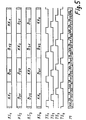
- FIG. 6 shows the multiplex signal M obtained in accordance with FIG. 5.
- the reception clock TE can initially have any phase position. Since there are four clocks with four different phase positions on the central side, four different phase positions are also interesting on the subscriber side. These are designated by TE in FIG. 6 under I to IV.
- KE denotes the bit sequences appearing for the line KE at the respective phase position of the reception clock TE at the output of the demultiplexer.
- the broadband signal obtained in this way is fed to the demodulator DEM via the line KE. Since none from the multiplexer Mux to the output of the demultiplexer Demux 1 If bits have been added or omitted, the transmission of the broadband signals as closed information blocks extends from the respective source Q 1 to Q k to the input of the demodulator DEM, which extracts the channel identifier KK and the CVBS signal B and the television sound by evaluating the frame identifier feeds the actual television FE.
- the channel identifier KK thus received and an identifier entered on an input keyboard ET of one of the television programs selected from the television programs P 1 to P m (see FIG. 1) are fed to a comparator V. None happens if there is a coincidence.
- the comparator V sends a control signal to the clock generator TG via the control line Stl, which is thereby stopped by the duration of one bit length of the multiplex signal M. It is thus achieved that the reception clock TE assumes the next of the possible phase positions with respect to the multiplex signal M and the corresponding broadband signal obtained reaches the demodulator DEM. This pause occurs until there is agreement between the received and the entered channel identifier.
- FIG. 4 it is described how the control line St1 provided according to FIG. 3 between the comparator V and the clock generator TG can be saved by using the line KE in addition for the transmission of the control signal from the comparator V to the clock generator TG. This is done by selecting an AC pulse with a frequency below the lowest frequency of the broadband signal or a DC pulse as the control signal and combining and separating both signals by the high-pass filters HP and HP 2 and the low-pass filters TP and TP 2 .
- the demodulator DEM, the comparator V and the input keyboard ET are in the actual television set FE or in its proximity, which is indicated by the common frame.
- the designation of this block with E 1 makes it clear that it corresponds to the television receiver E 1 shown in FIG.
- the system according to the invention is characterized by a simple clock supply. Only the few sources for the television programs have to be supplied with clocks which are synchronized with one another, which requires the clock line designated TL in FIG. 1. The clocks only need to be synchronized with one another, a specific phase relationship to one another is not required, because with the broadband signals present at the inputs of the multiplexers in the central stations, no specific phase relationship with one another is required.
- the system according to the invention also has the advantage that, because of the use of digital broadband signals, fiber optic cables can be used both between the sources and central stations and in the distribution network, as a result of which a substantial reduction in cable costs in the distribution network is achieved.
- fiber optic cables can be used both between the sources and central stations and in the distribution network, as a result of which a substantial reduction in cable costs in the distribution network is achieved.
- the usability of glass fibers has the advantage that cables designed for other services can also be used.
- a separate standard clock source can be omitted if an existing network intended for the supply of other digital telecommunications systems is also used to distribute a standard clock.
- an existing network intended for the supply of other digital telecommunications systems is also used to distribute a standard clock.
- Simple clock generators in the sources Q 1 to Q k result if the bit rates are selected as integer multiples of this standard clock. For example, a bitrate of 34.816 Mbit / s is achieved with a seventeen-fold increase. Whether you choose this or double (69.632 Mbit / s) or quadruple (139.264 Mbit / s) bit rate for the broadband signals depends on how much effort is required to reduce the redundancy and the associated bandwidth reduction of the image signal. This consideration also applies for which bit rate the many connecting lines, transmission-side multiplexers and subscriber-side demultiplexers can be produced economically.
- the broadband signals all have the same bit rate. This is advantageous if only services of the same type are to be transmitted.
- the broadband signals have different bit rates, the higher bit rates being integer multiples of the lowest bit rate.
- FIGS. 1 to 4 and the associated text also apply here analogously.
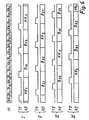
- This difference is explained on the basis of FIGS. 7 to 9, FIG. 7 relating to the formation of the multiplex signal M in the central multiplexer.
- FIG. 5 this is also accepted for the sake of simplicity of illustration men that the multiplexer has only the three inputs KS, to KS 3 , the inputs KS 1 and KS 2 for the low bit rate and the input KS 3 for the double bit rate.
- the multiplexing also takes place again by means of several clock-shifted clocks TS 1 , TS 2 , TS 3 , TS 3 ', the clocks TS 1 and TS 2 being assigned to the inputs KS 1 and KS 2 , respectively.
- the two clocks TS 3 and TS 3 t are assigned to the input KS 3 , their phase position relative to the broadband signal being selected such that each positive clock pulse samples a different bit of this broadband signal.
- the broadband signals must also be bit-edge-synchronous here; a specific phase relationship of their significant bits to each other is not required here either. Therefore, the channel identification bits have not been specifically designated here.
- the designation of the individual bits now only indicates which of the inputs KS 1 to KS 3 they are assigned to and the number of bits in the short section of the broadband signal in question, which is considered here.
- the selection of the desired broadband signal is carried out as in the first exemplary embodiment, i.e. as described with reference to Figures 3 and 4.
- integer multiples of the broadband signals of high bit rate enables a similarly simple construction of the multiplexers and demultiplexers as for systems with the same bit rate of all broadband signals.
- the multiplex signal M is obtained by bit-wise interleaving. Instead, however, word-by-word nesting is also possible.
- Word-by-word interleaving has the advantage over bit-wise that in the demodulator DEM (FIG. 3) the frame identifier is recognized faster, the channel identifier is extracted faster and the desired television program is switched through more quickly.
- bitwise nesting has the advantage that bit streams with a high bit rate can be handled more easily in the multiplexer and demultiplexer.
Abstract
Description
Die Erfindung betrifft ein Breitband-Verteil-Kommunikationssystem nach dem Oberbegriff des Patentanspruches 1. Ein solches System ist in der Zeitschrift "Unterrichtsblätter der Deutschen Bundespost" Ausg. B, Fernmeldewesen, Jg. 35/1982, Nr. 3, Seiten 139 bis 164 beschrieben.The invention relates to a broadband distribution communication system according to the preamble of
Im Abschnitt 4.1 des oben genannten Aufsatzes ist beschrieben, daß einer Zentrale (Rundfunkempfangsstelle) als Breitbandsignale die Fernsehprogramme der Rundfunkanstalten und der örtlichen Programmanbieter zugeleitet werden. Als Quellen dieser Fernsehprogramme bzw. Breitbandsignale sind also die Studios der Rundfunkanstalten und der örtlichen Programmanbieter anzusehen.In section 4.1 of the above-mentioned article it is described that the television programs of the broadcasters and the local program providers are sent to a central office (broadcaster receiving station) as broadband signals. The sources of these television programs or broadband signals are therefore the studios of the broadcasters and the local program providers.
Die Fernsehprogramme werden der Zentrale (Rundfunkempfangsstelle) in der gleichen Signalform zugeleitet, in der sie auch zum unmittelbaren drahtlosen Empfang durch Teilnehmer ausgestrahlt werden. Hierbei werden bei Farbfernsehprogrammen aus Kompatibilitätsgründen mit Schwarz-Weiß-Fernsehprogrammen bandbreitenvermindernde Modulationsverfahren, wie z.B. NTSC, PAL, SECAM angewendet. Solche bandbreitenvermindernde Modulationsverfahren sind immer mit Qualitätseinbußen verbunden.The television programs are forwarded to the head office (radio reception center) in the same signal form in which they are also broadcast for direct wireless reception by participants. In the case of color television programs, for reasons of compatibility with black and white television programs, bandwidth-reducing modulation methods, such as NTSC, PAL, SECAM applied. Such bandwidth-reducing modulation methods are always associated with quality losses.
Diese Breitbandsignale werden in der Zentrale nach der analogen Multiplextechnik zu einem Multiplexsignal aufbereitet und über ein Verteilnetz den Teilnehmern zugeleitet, wobei aus bandbreitenökonomischen Gründen die zuvor erwähnten bandbreitenvermindernden Modulationsverfahren beibehalten werden. Als Teilnehmer werden die Einrichtungen einer Wohnung angesehen. In ihr befinden sich ein oder mehrere Fern-sehempfänger als Wiedergabegeräte für die Breitbandsignale.These broadband signals are processed in the control center according to the analog multiplex technique to a multiplex signal and fed to the subscribers via a distribution network, the bandwidth-reducing modulation methods mentioned above being retained for bandwidth-economical reasons. The facilities of an apartment are viewed as participants. There are one or more remote vision receivers as playback devices for the wideband signals.
Wie in den Tabellen 1 bis 3 der o.g. Unterrichtsblätter angegeben ist, werden an das Verteilnetz des bekannten Systems sehr hohe und eng tolerierte übertragungstechnische Forderungen gestellt, was einen hohen Aufwand für Kabel, Verstärker, Umsetzer usw. zur Folge hat. Die in einem solchen System verwendeten Kabel sind in dem von der Anmelderin herausgegebenen Prospekt "Empfangs- und übertragungseinrichtungen für moderne Breitband-Kommunikationsanlagen", Bestell-Nr. ANT 1445 a 07.83, ausführlich beschrieben. Gemäß Seite 18 werden in den höheren Netzebenen Koaxial-Kabel mit einem massiven kupfernen Innenleiter mit bis zu 4,9 mm Durchmesser verwendet. Der ebenfalls kupferne Außenleiter weist bis zu 20 mm Außendurchmesser auf. Dies hat einen großen Aufwand an teuren Werkstoffen zur Folge.As in Tables 1 to 3 of the above. Teaching sheets are specified, very high and tightly tolerated transmission requirements are placed on the distribution network of the known system, which results in a high expenditure for cables, amplifiers, converters, etc. The cables used in such a system are described in the prospectus "Receiving and transmission equipment for modern broadband communication systems", order no. ANT 1445 a 07.83, described in detail. According to page 18, coaxial cables with a solid copper inner conductor with a diameter of up to 4.9 mm are used in the higher network levels. The outer conductor, which is also copper, has an outer diameter of up to 20 mm. This results in a large amount of expensive materials.
Das bekannte System weist nur eine einzige Zentrale (Rundfunkempfangsstelle) auf und ist deshalb nur für die Versorgung eines verhältnismäßig kleinen Gebietes, z.B. einer Stadt, geeignet. Eine landesweite Versorgung läßt sich durch mehrfache Anwendung des bekannten Systemes erreichen, indem man das Land in genügend kleine Gebiete unterteilt und in jedem Gebiet ein eigenes System mit einer eigenen Zentrale einrichtet. Jedoch vervielfacht sich damit auch der schon wegen der hohen übertragungstechnischen Forderungen hoher Aufwand für die Umsetzer zur Bildung des analogen Multiplexsignals.The known system has only a single center (radio receiving point) and is therefore only for the coverage of a relatively small area, e.g. a city suitable. A nationwide supply can be achieved by using the known system several times, by dividing the country into sufficiently small areas and setting up a separate system with its own headquarters in each area. However, the effort required for the converters to form the analog multiplex signal, which is high because of the high transmission requirements, is also multiplied.
Der Erfindung liegt die Aufgabe zu Grunde, ein Breitband-Verteil-Kommunikationssystem anzugeben, welches folgenden Bedingungen genügt:
- a) Geringere übertragungstechnische Forderungen an die Geräte ohne Qualitäteinbuße des wiedergegebenen Fernsehbildes,
- b) geringere Kabelkosten,
- c) landesweite Versorgung.
- a) Lower transmission requirements for the devices without loss of quality of the reproduced television picture,
- b) lower cable costs,
- c) Nationwide supply.
Diese Aufgabe wird durch die kennzeichnenden Merkmale des Patentanspruches 1 gelöst.This object is achieved by the characterizing features of
Die Erfindung wird an Hand von in den Figuren 1 bis 9 dargestellten Ausführungsbeispielen erläutert, wobei die Figuren 1 bis 6 ein Beispiel gemäß dem Patentanspruch 2 betreffen. Die Figuren 7 bis 9 betreffen ein Ausführungsbeispiel nach dem Patentanspruch 3. Da jeder der Ansprüche 2 und 3 auf den Anspruch 1 zurückbezogen ist, kann jedes dieser Beispiele auch zur Erläuterung eines Systems nach dem Anspruch 1 dienen.The invention is explained on the basis of exemplary embodiments shown in FIGS. 1 to 9, with FIGS. 1 to 6 relating to an example according to
Es wird zunächst das Ausführungsbeispiel für den Patentanspruch 2 nach den Figuren 1 bis 6 beschrieben. Die Figur 1 gibt eine übersicht über das erfindungsgemäße Breitband-Verteil-Kommunikationssystem, die Figuren 2 bis 4 geben Einzelheiten desselben wieder. An Hand der Figuren 5 und 6 wird die Funktion einzelner Baugruppen verdeutlicht.The exemplary embodiment for
Es bedeuten in der Figur 1:
- Q1...Qk: k Quellen für Breitbandsignale
- TL: eine Taktleitung
- NTQ: eine Normtaktquelle
- P1...Pm m Fernsehprogramme als Breitbandsignale
- Z1...Zx: x Zentralen
- Mux: ein Multiplexer KS1...KSm: m Eingänge des Multiplexers
- VN: ein Verteilnetz
- T1...Ty: y Teilnehmer
- Q 1 ... Q k : k sources for broadband signals
- TL: a clock line
- NTQ: a standard clock source
- P 1 ... P m m television programs as broadband signals
- Z 1 ... Z x : x central units
- Mux: a multiplexer KS 1 ... KSm: m inputs of the multiplexer
- VN: a distribution network
- T 1 ... T y : y participants
In den Quellen Q1 bis QK werden die dort produzierten oder von außerhalb zugeführten Fernsehprogramme zu digitalen Breitbandsignalen P1 bis Pm mit einheitlicher Bitrate und einheitlichem Rahmenaufbau aufbereitet. Jeder Rahmen weist neben den Bits zur übertragung des FBAS-Signals und des zugehörigen Tones weitere Bits auf für eine bei allen digitale Breitbandsignalen einheitliche Rahmenkennung sowie für eine für jedes der Fernsehprogramme P, bis Pm indivuelle Kanalkennung. Diese liegt, bezogen auf die Rahmenkennung, immer am gleichen Platz.In the sources Q 1 to Q K , the television programs produced there or supplied from outside are processed into digital broadband signals P 1 to P m with a uniform bit rate and a uniform frame structure. In addition to the bits for the transmission of the composite signal and the associated sound, each frame has further bits for a frame identifier that is uniform for all digital broadband signals and for an individual channel identifier for each of the
Im Extremfall ist für jedes der Breitbandsignale eine eigene Quelle vorgesehen. Als Quellen kann man die Studios der Rundfunkanstalten und die der lokalen Programmanbieter ansehen.In extreme cases, a separate source is provided for each of the broadband signals. The studios of the broadcasting companies and those of the local program providers can be seen as sources.
Die Aufbereitung auf gleiche Bitrate ist besonders einfach möglich, wenn eine für alle Quellen gemeinsame Normtaktquelle NTQ vorgesehen ist. Der in ihr erzeugte Normtakt wird über die Taktleitung TL an alle Quellen Q1 bis Qk übertragen, wo durch Vervielfachen und/oder Teilen und/oder Synchronisieren örtlicher Taktgeneratoren die zum Aufbereiten auf einheitliche Bitrate notwendigen synchronen Takte erzeugt werden.Processing to the same bit rate is particularly easy if a standard clock source NTQ is provided for all sources. The standard clock generated in it is transmitted via the clock line TL to all sources Q 1 to Q k , where by multiplying and / or dividing and / or synchronizing local clock generators, the synchronous clocks necessary for processing to a uniform bit rate are generated.
Die Fernsehprogramme bzw. digitalen Breitbandsignale P, bis Pm werden den Eingängen KS1 bis KSm der Multiplexer Mux in den Zentralen Z1 bis Zx zugeleitet, wobei für jedes Fernsehprogramm ein eigener physikalischer Leiter oder auch Multiplexausnutzung von wenigen Leitern vorgesehen sein kann. An jede Zentrale sind über ein Verteilnetz VN viele Teilnehmer angeschlossen. Die Teilnehmer der Zentrale Z1 sind mit T1 bis Ty bezeichnet. Im Multiplexer M werden die digitalen Breitbandsignale P1 bis Pm zu einem Multiplexsignal M zusammengefaßt, welches über das Verteilnetz VN an alle Teilnehmer T1 bis Ty übertragen wird.The television programs or digital broadband signals P, to P m are fed to the inputs KS 1 to KS m of the multiplexers Mux in the control centers Z 1 to Z x , it being possible for a separate physical conductor or multiplex utilization of a few conductors to be provided for each television program. Many participants are connected to each control center via a distribution network VN. The participants in the central office Z 1 are designated T 1 to Ty. In the multiplexer M, the digital broadband signals P 1 to P m are combined to form a multiplex signal M which is transmitted to all subscribers T 1 to Ty via the distribution network VN.
Weitere Einzelheiten werden an Hand der Figur 2 erläutert. In ihr ist links unten die Zentrale Z1 mit dem Multiplexer Mux und seinen Eingängen KS1 bis KSm dargestellt. Ferner ist einer der Teilnehmer, nämlich der Teilnehmer T1, ausführlich dargestellt. Als Teilnehmer werden hier die Einrichtungen in einer Wohnung verstanden. Diese bestehen aus einer Teilnehmerschalteeinheit TAE, einer Wohnungsverkabelung WK, den Demultiplexern Demux1 bis Demuxp und den Fernsehempfängern E1 bis Ep.Further details are explained with reference to FIG. 2. It shows the central station Z 1 with the multiplexer Mux and its inputs KS 1 to KS m at the bottom left. Furthermore, one of the participants, namely participant T 1 , is shown in detail. Here, the participants understand the facilities in an apartment. These consist of a subscriber switching unit TAE, an apartment wiring WK, the demultiplexers Demux 1 to Demuxp and the television receivers E 1 to Ep.
In der Teilnehmeranschalteeinheit TAE wird das über das Verteilnetz VN übertragene digitale Multiplexsignal M in eine zur Übertragung über die Wohnungsverkabelung WK geeignete Form umgesetzt. An ihr sind die Fernsehempfänger E1 bis Ep über die ihnen zugeordnete Demultiplexer Demux1 bis Demuxp angeschlossen. In jedem dieser Demultiplexer wird aus dem Multiplexsignal M dasjenige Breitbandsignal gewonnen, welches dem an dem betr. Fernsehempfänger gewünschten Programm entspricht.In the subscriber interface unit TAE, the digital multiplex signal M transmitted via the distribution network VN is converted into a form suitable for transmission via the apartment wiring WK. The television receivers E 1 to Ep are connected to it via the demultiplexers Demux 1 to Demuxp assigned to them. In each of these demultiplexers, the multiplex signal M is used to obtain the broadband signal which corresponds to the program desired on the television receiver concerned.
Die Wohnungsverkabelung Wk kann verschieden ausgeführt sein:
- a) sammelschienenförmig, wie in
der Figur 2 dargestellt, - b) sternförmig
- c) in einer Mischform aus a) und b).
- a) busbar-shaped, as shown in Figure 2,
- b) star-shaped
- c) in a mixture of a) and b).
Die Demultiplexer Demux1 bis Demuxp befinden sich in der Nähe der betr. Fernsehempfänger, z.B. in einer Anschlußdose. Bei sternförmiger Wohnungsverkabelung können die Demultiplexer auch in der Teilnehmeranschalteeinheit TAE untergebracht sein, dies gilt auch für die Mischform nach c). Bei der Form nach a) und c) können von der Teilnehmeranschalteeinheit TAE mehrere Sammelschienen ausgehen. Welche Verkabelungsform gewählt wird, richtet sich bei gegebenem Wohnungsgrundriß nach wirtschaftlichen Gesichtspunkten, insbesondere, um kurze Kabellängen zu erreichen. Zwecks leichter Montage und geringer Lagerhaltung sind die Teilnehmeranschalteeinheiten so ausgestaltet, daß sie leicht an jede der möglichen Form der Wohnungsverkabelung angepaßt werden können.The demultiplexers Demux 1 to Demuxp are nearby hey the television receiver concerned, eg in a junction box. With star-shaped apartment cabling, the demultiplexers can also be accommodated in the subscriber interface unit TAE, this also applies to the mixed form according to c). In the form according to a) and c), multiple busbars can originate from the subscriber interface unit TAE. Which type of cabling is chosen depends on economic considerations for a given floor plan, in particular in order to achieve short cable lengths. For ease of assembly and low inventory, the subscriber interface units are designed so that they can be easily adapted to any form of home wiring.
Um das Wiedergewinnen des jeweils gewünschten Breitbandkanals in einem der Demultiplexer erläutern zu können, muß zuvor die Multiplexbildung im zentralenseitigen Multiplexer erklärt werden. Dies geschieht an Hand der Figur 5. Zwecks einfacherer Darstellung wird angenommen, daß der Multiplexer nur vier Eingänge, nämlich die Eingänge KS1 bis KS4 aufweist, d.h. die Zahl m ist hier zu 4 angenommen und das beispielhafte System ist für vier Fernsehprogramme bemessen. Jedoch kann das erfindungsgemäße System auch für m = 12, also für 12 Fernsehprogramme wie das bekannte System oder für eine noch größere Zahl bemessen werden.In order to be able to explain the recovery of the desired broadband channel in one of the demultiplexers, the multiplex formation in the central-side multiplexer must be explained beforehand. This is done with the aid of FIG. 5. For the sake of simplicity, it is assumed that the multiplexer has only four inputs, namely the inputs KS 1 to KS 4 , ie the number m is assumed to be 4 and the exemplary system is dimensioned for four television programs. However, the system according to the invention can also be dimensioned for m = 12, ie for 12 television programs like the known system or for an even larger number.
In der Figur 5 sind in den Zeilen KS1 bis KS4 Ausschnitte von je 4 Bits der an den gleichnamigen Eingängen des Multiplexers Mux anliegenden bitratengleichen und bitflankensynchronen Breitbandsignale gezeichnet. Sie gelangen von den Quellen Q1 bis Qk als geschlossene Informationsblöcke bis hierher, d. h., in demjenigen Rahmenaufbau, wie sie in den Quellen Q1 bis Qk aufbereitet werden, also mit Rahmen- und Kanalkennung sowie FBAS-Signal und Fernsehton ohne jede weiteren Zusätze.In FIG. 5, lines KS 1 to KS 4 show sections of 4 bits each of the bit-rate and bit-edge-synchronous broadband signals present at the inputs of the same name in the multiplexer Mux. You get from the sources Q 1 to Q k as closed information blocks up to here, ie in the frame structure as they are prepared in the sources Q 1 to Q k , i.e. with frame and channel identification as well as composite signal and television sound without any other additives.
Mit KK... sind die die Kanalkennung und mit B... die das FBAS-Signal bzw. den Fernsehton tragenden Bits bezeichnet. Indizes geben die Zugehörigkeit zu den einzelnen Kanälen und bei den mit B bezeichneten Bits auch noch ihre Reihenfolge untereinander an. Auf die Darstellung von Rahmenkennungsbits wurde verzichtet. Die Phasenlage von signifikanten Bits (Rahmenkennungs- und Kanalkennungsbits) eines Breitbandsignals zu denjenigen jedes anderen Breitbandsignals ist beliebig.KK ... denotes the channel identifier and B ... denotes the bits carrying the composite signal or the television sound. Indices indicate the affiliation to the individual channels and, in the case of the bits designated with B, their order among themselves. The display of frame identifier bits has been omitted. The phase relationship of significant bits (frame identifier and channel identifier bits) of a broadband signal to that of any other broadband signal is arbitrary.
Im Multiplexer Mux werden diese vier Breitbandsignale bitweise verschachtelt ohne daß eine überrahmenkennung hinzugefügt wird. Das so gewonnene und mit M bezeichnete Multiplexsignal weist also genau die vierfache Bitrate der einzelnen Breitbandsignale auf. Ein solcher Multiplexer ist im Prinzip aus mehreren, von untereinander phasenverschobenen und gegenüber den zu verschachtelnden Signalen flankensynchronen Takten durchlässig gesteuerte Torschaltungen aufgebaut. Da hier vier Breitbandsignale vorliegen, sind dementsprechend vier Takte TS1 bis TS4 vorgesehen, wobei durch die Indizes ihre Zuordnung zu den Breitbandsignalen KS1 bis KS4 angegeben ist. Die einzelnen Bits im Multiplexsignal M sind gleichlautend mit denen der einzelnen Breitbandsignale bezeichnet. So ist zu erkennen, in welcher Reihenfolge, durch die positiven Impulse der Takte gesteuert, die einzelnen Bits der Breitbandsignale zu dem Multiplexsignal zusammengefügt werden.In the multiplexer Mux, these four broadband signals are interleaved bit by bit without an overframe identifier being added. The multiplex signal obtained in this way and designated M thus has exactly four times the bit rate of the individual broadband signals. In principle, such a multiplexer is made up of a plurality of gate circuits which are phase-shifted from one another and are edge-synchronous with respect to the signals to be interleaved, and which are controlled. Since there are four broadband signals here, four clocks TS 1 to TS 4 are accordingly provided, their assignment to the broadband signals KS 1 to KS 4 being indicated by the indices. The individual bits in the multiplex signal M have the same name as those of the individual broadband signals. It can be seen in what order, controlled by the positive pulses of the clocks, the individual bits of the broadband signals are combined to form the multiplex signal.
Die vier Takte TS1 bis TS4 werden in nicht dargestellter Weise aus den an den Eingängen KS1 bis KS4 anliegenden Breitbandsignalen gewonnen, wodurch der geforderte Bitflankensynchronismus leicht herstellbar ist. Die vier Takte müssen untereinander die in der Fig. 5 angegebene Phasenlage aufweisen, eine bestimmte Phasenlage gegenüber signifikanten Bits der Breitbandsignale wird nicht gefordert.The four clocks TS 1 to TS 4 are obtained in a manner not shown from the wideband signals present at the inputs KS 1 to KS 4 , as a result of which the required bit edge synchronization can be easily produced. The four clocks must have the phase position shown in FIG. 5 indicate, a certain phase position with respect to significant bits of the broadband signals is not required.
Wie teilnehmerseitig aus diesem Multiplexsignal M das dem gewünschten Fernsehprogramm entsprechende Breitbandsignal gewonnen wird, sei an Hand der Figuren 3 und 6 beschrieben.How the broadband signal corresponding to the desired television program is obtained on the subscriber side from this multiplex signal M will be described with reference to FIGS. 3 and 6.
In der Figur 3 ist einer der Demultiplexer, hier Demux1/gezeichnet. Er enthält einen hier separat gezeichneten Taktgenerator TG, welcher einen zum Multiplexsignal M bitflankensynchrone Empfangstakt TE aus diesem Multiplexsignal erzeugt. Auch ein Demultiplexer ist im Prinzip aus von Takten gesteuerten Torschaltungen aufgebaut. Da hier nur eines der Breitbandsignale gewonnen werden soll, genügt eine Torschaltung und ein Empfangstakt TE.FIG. 3 shows one of the demultiplexers, here Demux 1 / . It contains a clock generator TG, shown separately here, which generates a reception clock TE synchronous to the multiplex signal M from this multiplex signal. In principle, a demultiplexer is also constructed from gate circuits controlled by clock cycles. Since only one of the broadband signals is to be obtained here, a gate circuit and a receive clock TE are sufficient.
In der Figur 6 ist zunächst wieder das gemäß der Figur 5 gewonnene Multiplexsignal M dargestellt. Zu diesem kann der Empfangstakt TE zunächst jede beliebige Phasenlage aufweisen. Da zentralenseitig vier Takte mit vier verschiedenen Phasenlagen vorhanden sind, sind auch teilnehmerseitig vier verschiedene Phasenlagen interessant. Diese sind in der Figur 6 unter I bis IV mit TE bezeichnet. Mit KE sind die bei der jeweiligen Phasenlage des Empfangstaktes TE am Ausgang des Demultiplexers für die Leitung KE erscheinenden Bitfolgen bezeichnet. Durch gleichlautende Bezeichnung der einzelnen Bits und Vergleich mit der Figur 5 erkennt man, daß je nach der Phasenlage des Empfangstaktes TE eines der an den Eingängen KS1 bis KS4 des Multiplexers Mux anliegenden Breitbandsignale erscheint.FIG. 6 shows the multiplex signal M obtained in accordance with FIG. 5. For this, the reception clock TE can initially have any phase position. Since there are four clocks with four different phase positions on the central side, four different phase positions are also interesting on the subscriber side. These are designated by TE in FIG. 6 under I to IV. KE denotes the bit sequences appearing for the line KE at the respective phase position of the reception clock TE at the output of the demultiplexer. By identifying the individual bits with the same name and comparing them with FIG. 5, it can be seen that, depending on the phase position of the reception clock TE, one of the broadband signals present at the inputs KS 1 to KS 4 of the multiplexer Mux appears.
Das jeweils so gewonnene Breitbandsignal wird über die Leitung KE dem Demodulator DEM zugeleitet. Da auch vom Multiplexer Mux bis zum Ausgang des Demultiplexers Demux1 keinerlei Bit hinzugefügt oder weggelassen wurden, reicht die übertragung der Breitbandsignale als geschlossene Informationsblöcke von der jeweiligen Quelle Q1 bis Qk bis zum Eingang des Demodulators DEM, welcher daraus durch Auswerten der Rahmenkennung die Kanalkennung KK extrahiert und das FBAS-Signal B sowie den Fernsehton dem eigentlichen Fernsehgerät FE zuleitet. Die so empfangene Kanalkennung KK und eine an einer Eingabetastatur ET eingegebene Kennung eines der aus den angebotenen Fernsehprogrammen P1 bis Pm (siehe Figur 1) ausgewählten Fernsehprogrammes werden einem Vergleicher V zugeführt. Bei zufälliger übereinstimmung geschieht weiter nichts. Bei Nichtübereinstimmung gibt der Vergleicher V über die Steuerleitung Stl ein Steuersignal an den Taktgenerator TG, welcher dadurch um die Dauer einer Bitlänge des Multiplexsignales M angehalten wird. So wird erreicht, daß der Empfangstakt TE die nächste der möglichen Phasenlagen bezüglich des Multiplexsignals M annimmt und das entsprechende gewonnene Breitbandsignal zum Demodulator DEM gelangt. Dieses Anhalten geschieht so oft bis übereinstimmung zwischen der empfangenen und der eingegebenen Kanalkennung erreicht ist.The broadband signal obtained in this way is fed to the demodulator DEM via the line KE. Since none from the multiplexer Mux to the output of the demultiplexer Demux 1 If bits have been added or omitted, the transmission of the broadband signals as closed information blocks extends from the respective source Q 1 to Q k to the input of the demodulator DEM, which extracts the channel identifier KK and the CVBS signal B and the television sound by evaluating the frame identifier feeds the actual television FE. The channel identifier KK thus received and an identifier entered on an input keyboard ET of one of the television programs selected from the television programs P 1 to P m (see FIG. 1) are fed to a comparator V. Nothing happens if there is a coincidence. In the event of a mismatch, the comparator V sends a control signal to the clock generator TG via the control line Stl, which is thereby stopped by the duration of one bit length of the multiplex signal M. It is thus achieved that the reception clock TE assumes the next of the possible phase positions with respect to the multiplex signal M and the corresponding broadband signal obtained reaches the demodulator DEM. This pause occurs until there is agreement between the received and the entered channel identifier.
An Hand der Figur 4 wird beschrieben, wie die lt. Figur 3 vorgesehene Steuerleitung Stl zwischen dem Vergleicher V und dem Taktgenerator TG eingespart werden kann, indem die Leitung KE zusätzlich zur übertragung des Steuersignals vom Vergleicher V zum Taktgenerator TG benutzt wird. Dies geschieht, indem als Steuersignal ein Wechselstromimpuls mit einer Frequenz unterhalb der niedrigsten Frequenz des Breitbandsignals oder ein Gleichstromimpuls gewählt wird und beide Signale durch die Hochpässe HP, und HP2 sowie die Tiefpässe TP, und TP2 zusammengefaßt bzw. wieder getrennt werden.Using FIG. 4, it is described how the control line St1 provided according to FIG. 3 between the comparator V and the clock generator TG can be saved by using the line KE in addition for the transmission of the control signal from the comparator V to the clock generator TG. This is done by selecting an AC pulse with a frequency below the lowest frequency of the broadband signal or a DC pulse as the control signal and combining and separating both signals by the high-pass filters HP and HP 2 and the low-pass filters TP and TP 2 .
Der Demodulator DEM, der Vergleicher V und die Eingabetastatur ET befinden sich im eigentlichen Fernsehgerät FE oder in dessen Nähe, was durch die gemeinsame Umrahmung angedeutet wird. Durch die Bezeichnung dieses Blockes mit E1 wird verdeutlicht, das er dem in der Figur 2 dargestellten Fernsehempfänger E1 entspricht.The demodulator DEM, the comparator V and the input keyboard ET are in the actual television set FE or in its proximity, which is indicated by the common frame. The designation of this block with E 1 makes it clear that it corresponds to the television receiver E 1 shown in FIG.
Das erfindungsgemäße System zeichnet sich durch eine einfache Taktversorgung aus. Nur die wenigen Quellen für die Fernsehprogramme müssen mit untereinander synchronen Takten versorgt werden, was die in der Figur 1 mit TL bezeichnete Taktleitung erfordert. Die Takte brauchen untereinander nur synchron zu sein, eine bestimmte Phasenlage zueinander wird nicht gefordert, weil bei den an den Eingängen der Multiplexer in den Zentralen anliegenden Breitbandsignalen auch keine bestimmte Phasenlage untereinander gefordert wird.The system according to the invention is characterized by a simple clock supply. Only the few sources for the television programs have to be supplied with clocks which are synchronized with one another, which requires the clock line designated TL in FIG. 1. The clocks only need to be synchronized with one another, a specific phase relationship to one another is not required, because with the broadband signals present at the inputs of the multiplexers in the central stations, no specific phase relationship with one another is required.
So betehen auch keine Forderungen hinsichtlich Laufzeiten auf den Taktleitungen.So there are no requirements regarding run times on the clock lines.
Da die in den in größerer Zahl vorhandenen Zentralen Z1 bis Zx und in den sehr vielen Demultiplexern vorgesehenen Taktgeneratoren nicht in einer bestimmten Phasenlage untereinander und in Beziehung zu signifikanten Bits der Breitbandsignalen laufen müssen, sind Synchronisierleitungen zu diesen Taktgeneratoren hin entbehrlich. Sie können vielmehr in einfacher Weise auf die jeweils vorhandenen Breitbandsignale synchronisiert werden. Durch die erfindungsgemäße digitale Aufbereitung in den Quellen und die erfindungsgemäße Bildung des Multiplexsignals in den Zentralen ist der Aufwand in den Zentralen nur gering und die Notwendigkeit mehrerer Zentralen bei landesweiter Versorgung kein Nachteil.Since the clock generators provided in larger numbers in the central units Z 1 to Z x and in the very many demultiplexers do not have to run in a specific phase relationship with one another and in relation to significant bits of the broadband signals, synchronization lines to these clock generators are unnecessary. Rather, they can be synchronized in a simple manner to the broadband signals present in each case. Due to the digital processing according to the invention in the sources and the formation of the multiplex signal according to the invention in the control centers, the effort in the control centers is only slight and the need for several control centers with nationwide coverage is not a disadvantage.
Das erfindungsgemäße System hat noch den Vorteil, daß wegen der Anwendung digitaler Breitbandsignale sowohl zwischen den Quellen und Zentralen als auch im Verteilnetz Glasfaserkabel eingesetzt werden können, wodurch eine wesentliche Verringerung der Kabelkosten im Verteilnetz erreicht wird. Für die übertragung zwischen den Quellen und den Zentralen ergibt sich so bei nur geringen Kabelkosten gegenüber dem bekannten System mit drahtloser Übertragung der Vorteil einer von atmosphärischen Störungen unbeeinflußte Übertragung.The system according to the invention also has the advantage that, because of the use of digital broadband signals, fiber optic cables can be used both between the sources and central stations and in the distribution network, as a result of which a substantial reduction in cable costs in the distribution network is achieved. For the transmission between the sources and the control centers results in only a low cable cost compared to the known system with wireless transmission, the advantage of a transmission unaffected by atmospheric disturbances.
Die Verwendbarkeit von Glasfasern hat den Vorteil, daß für andere Dienste ausgelegte Kabel mitbenutzt werden können.The usability of glass fibers has the advantage that cables designed for other services can also be used.
Die Anwendung digitaler Breitbandsignale hat ferner den Vorteil, daß von den bandbreitenvermindernden, jedoch auch qualitätsmindernden Modulationsverfahren kein Gebrauch gemacht werden muß.The use of digital broadband signals also has the advantage that the bandwidth-reducing but also quality-reducing modulation methods do not have to be used.
Eine eigene Normtaktquelle kann entfallen, wenn ein schon vorhandenes, für die Versorgung anderer digitaler Fernmeldesysteme vorgesehenes Netz zur Verteilung eines Normtaktes mitbenutzt wird. Wie im Taschenbuch der Fernmeldepraxis 1984, Fachverlag Schiele und Schön, Berlin, auf den Seiten 70 bis 104 in dem Aufsatz "Synchronisierung des digitalen Fernmeldenetzes der DBP" beschrieben ist, haben die Post-und Fernmeldeverwaltungen solche Netze aufgebaut, wobei die Deutsche Bundespost sich für einen Normtakt von 2048 kHz entschlossen hat.A separate standard clock source can be omitted if an existing network intended for the supply of other digital telecommunications systems is also used to distribute a standard clock. As described in the paperback of the Telecommunications Practice 1984, Fachverlag Schiele and Schön, Berlin, on pages 70 to 104 in the article "Synchronization of the digital telecommunications network of the DBP", the post and telecommunications administrations have set up such networks, with the Deutsche Bundespost advocating for has decided a standard clock of 2048 kHz.
Einfache Taktgeneratoren in den Quellen Q1 bis Qk ergeben sich, wenn man die Bitraten als ganzzahlige Vielfache dieses Normtaktes wählt. So kommt man z.B. bei einer Versiebzehnfachung auf eine Bitrate von 34,816 Mbit/s. Ob man diese oder die doppelte (69,632 Mbit/s) oder die vierfache (139,264 Mbit/s) Bitrate für die Breitbandsignale wählt, hängt davon ab, wie hoch man den Aufwand für die Redundanzverminderung und die damit verbundene Bandbreitenverminderung des Bildsignals treibt. In diese Betrachtung geht auch ein, für welche Bitrate sich die vielen Anschlußleitungen, sendeseitigen Multiplexer und teilnehmerseitigen Demultiplexer wirtschaftlich herstellen lassen.Simple clock generators in the sources Q 1 to Q k result if the bit rates are selected as integer multiples of this standard clock. For example, a bitrate of 34.816 Mbit / s is achieved with a seventeen-fold increase. Whether you choose this or double (69.632 Mbit / s) or quadruple (139.264 Mbit / s) bit rate for the broadband signals depends on how much effort is required to reduce the redundancy and the associated bandwidth reduction of the image signal. This consideration also applies for which bit rate the many connecting lines, transmission-side multiplexers and subscriber-side demultiplexers can be produced economically.
In dem zuvor beschriebenen, den Anspruch 2 betreffenden Beispiel weisen die Breitbandsignale alle die gleiche Bitrate auf. Dies ist dann vorteilhaft, wenn nur gleichartige Dienste übertragen werden sollen. Demgegenüber weisen in dem System nach dem Patentanspruch 3 die Breitbandsignale unterschiedliche Bitraten auf, wobei die höheren Bitraten ganzzahlige Vielfache der geringsten Bitrate sind.In the example described above, which relates to claim 2, the broadband signals all have the same bit rate. This is advantageous if only services of the same type are to be transmitted. In contrast, in the system according to
Dadurch wird erreicht:
- - Wenn neben den Fernsehprogrammen Dienste mit geringerer Bandbreite, z.B. Tonrundfunkprogramme, übertragen werden sollen, so sieht man hierfür einen oder mehrere Breitbandkanäle mit geringerer Bitrate vor, wobei die geringere Bitrate an die geringere Bandbreite dieser Dienste angepaßt wird, wodurch die Bitrate des Multiplexsignals M nicht höher wird als notwendig.
- - Wenn man für die jetzt üblichen Fernsehprogramme mit 625 Zellen pro Bild eine Bitrate von z.B. 34,816 Mbit/s festlegt, kann man leicht hochzeilige Fernsehprogramme mit entsprechend höherer Bildqualität einführen und dafür z.B. die doppelte Bitrate festlegen.
- If, in addition to the television programs, services with a lower bandwidth, for example audio broadcasting programs, are to be transmitted, one or more broadband channels with a lower bit rate are provided for this purpose, the lower bit rate being adapted to the lower bandwidth of these services, as a result of which the bit rate of the multiplex signal M is not becomes higher than necessary.
- - If you set a bit rate of, for example, 34.816 Mbit / s for the now common television programs with 625 cells per picture, you can easily introduce high-line television programs with a correspondingly higher picture quality and, for example, set the double bit rate.
Ein entsprechendes Auführungsbeispiel unterscheidet sich von dem zuvor beschriebenen durch die Bildung des Multiplexsignals, so daß die Figuren 1 bis 4 und der zugehörige Text sinngemäß auch hier gelten. Dieser Unterschied wird an Hand der Figuren 7 bis 9 erläutert, wobei die Figur 7 das Bilden des Multiplexsignals M im zentralenseitigen Multiplexer betrifft. Im Gegensatz zur Figur 5 ist hier ebenfalls aus Gründen der einfacheren Darstellung angenommen, daß der Multiplexer nur die drei Eingänge KS, bis KS3 aufweist, wobei die Eingänge KS1 sowie KS2 für die niedrige Bitrate und der Eingang KS3 für die doppelte Bitrate bestimmt ist. Die Multiplexbildung geschieht auch wieder durch mehrere untereinander phasenverschobene Takte TS1, TS2, TS3, TS3', wobei die Takte TS1 und TS2 den Eingängen KS1, bzw. KS2 zugeordnet sind. Dem Eingang KS3 sind die beiden Takte TS3 und TS3 t zugeordnet, wobei ihre Phasenlage gegenüber dem Breitbandsignal so gewählt ist, daß jeder positive Taktimpuls ein anderes Bit dieses Breitbandsignales abtastet. Wie im Fall der Figur 5 müssen auch hier die Breitbandsignale bitflankensynchron sein; eine bestimmte Phasenlage ihrer signifikanten Bits zueinander wird auch hier nicht gefordert. Deshalb wurden hier die Kanalkennungsbits nicht eigens bezeichnet. Die Bezeichnung der einzelnen Bits gibt jetzt nur noch an, welchem der Eingänge KS1 bis KS3 sie zugeordnet sind und das wievielte Bit es in dem kurzen, hier betrachteten Ausschnitt des betr. Breitbandsignals ist.A corresponding exemplary embodiment differs from that described above by the formation of the multiplex signal, so that FIGS. 1 to 4 and the associated text also apply here analogously. This difference is explained on the basis of FIGS. 7 to 9, FIG. 7 relating to the formation of the multiplex signal M in the central multiplexer. In contrast to FIG. 5, this is also accepted for the sake of simplicity of illustration men that the multiplexer has only the three inputs KS, to KS 3 , the inputs KS 1 and KS 2 for the low bit rate and the input KS 3 for the double bit rate. The multiplexing also takes place again by means of several clock-shifted clocks TS 1 , TS 2 , TS 3 , TS 3 ', the clocks TS 1 and TS 2 being assigned to the inputs KS 1 and KS 2 , respectively. The two clocks TS 3 and TS 3 t are assigned to the input KS 3 , their phase position relative to the broadband signal being selected such that each positive clock pulse samples a different bit of this broadband signal. As in the case of FIG. 5, the broadband signals must also be bit-edge-synchronous here; a specific phase relationship of their significant bits to each other is not required here either. Therefore, the channel identification bits have not been specifically designated here. The designation of the individual bits now only indicates which of the inputs KS 1 to KS 3 they are assigned to and the number of bits in the short section of the broadband signal in question, which is considered here.
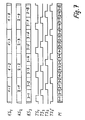
An Hand der Figur 8 wird das Wiedergewinnen eines Breitbandsignals mit der geringen Bitrate in einem dafür gestalteten teilnehmerseitigen Demultiplexer erklärt. Es gilt hier sinngemäß der Text zur Figur 6. Bei zwei der möglichen Phasenlagen des Empfangstaktes TE, nämlich bei der unter I und III angegebenen, wird jeweils eines der Breitbandsignale wiedergewonnen. Dagegen erscheinen bei den anderen zwei möglichen Phasenlagen unbrauchbare Teile des Breitbandsignals mit der hohen Bitrate.The recovery of a broadband signal with the low bit rate in a subscriber-side demultiplexer designed for this is explained with reference to FIG. The text for FIG. 6 applies here analogously. In two of the possible phase positions of the receive clock TE, namely in the case indicated under I and III, one of the broadband signals is recovered. In contrast, unusable parts of the broadband signal with the high bit rate appear in the other two possible phase positions.
An Hand der Figur 9 wird das Widergewinnen des Breitbandsignals mit der hohen Bitrate beschrieben. Auch hier gilt sinngemäß der Text zur Figur 6; da aber zentralenseitig zwei Takte notwendig sind, müssen in dem für das Breitbandsignal hoher Bitrate bemessenen Demultiplexer zwei Empfangstakte TE und TE' mit der gleichen Phasenlage untereinander vorgesehen werden. Es kann aber auch ein einziger Takt mit der doppelten Frequenz, wie er sich aus der Überlagerung von TE und TE' ergibt, verwendet werden. Es ergeben sich wieder vier verschiedene mögliche Phasenlage dieser zwei Empfangstakte TE und TE' gegenüber dem Multiplexsignal M; bei zweien, nämlich den unter II und IV angegebenen, wird das Breitbandsignal hoher Bitrate richtig wiedergewonnen, bei den beiden anderen Möglichkeiten erscheint eine unbrauchbare Bitfolge aus den Breitbandsignalen niedriger Bitrate.The recovery of the broadband signal with the high bit rate is described with reference to FIG. 9. The text for FIG. 6 also applies here analogously; however, since two clocks are required on the central side, two receive clocks TE must be used in the demultiplexer designed for the high bit rate broadband signal and TE 'can be provided with the same phase relationship with one another. However, it is also possible to use a single clock with twice the frequency, which results from the superposition of TE and TE '. There are four different possible phase positions of these two reception clocks TE and TE 'compared to the multiplex signal M; with two, namely those specified under II and IV, the broadband signal of high bit rate is correctly recovered, with the other two options an unusable bit sequence appears from the broadband signals of low bit rate.
Die Auswahl des gewünschten Breitbandsignals, wenn mehrere solcher mit hoher Bitrate vorgesehen sind auch bei diesen, geschieht wie bei dem ersten Ausführungsbeispiel, d.h. wie an Hand der Figuren 3 und 4 beschrieben.The selection of the desired broadband signal, if a plurality of those with a high bit rate are also provided for these, is carried out as in the first exemplary embodiment, i.e. as described with reference to Figures 3 and 4.
Durch die Beschränkung auf ganzzahlige Vielfache bei den Breitbandsignalen hoher Bitrate wird ein ähnlich einfacher Aufbau der Multiplexer und Demultiplexer ermöglicht wie bei den Systemen mit gleicher Bitrate aller Breitbandsignale. Man braucht nur die Bits des Multiplexsignals M im Verhältnis der Bitraten der Breitbandsignale diesen zuzuordnen, d.h., dem mit der niedrigsten Bitrate wird ein Bit, dem mit der doppelten Bitrate werden zwei Bits, dem mit der dreifachen Bitrate werden drei Bits aus einer Periode des Multiplexsignals zugeordnet.The limitation to integer multiples of the broadband signals of high bit rate enables a similarly simple construction of the multiplexers and demultiplexers as for systems with the same bit rate of all broadband signals. One need only assign the bits of the multiplex signal M in relation to the bit rates of the wideband signals, ie, the bit with the lowest bit rate becomes one bit, the bit rate with two bits becomes two bits, and the triple bit rate becomes three bits from one period of the multiplex signal assigned.
In den zuvor beschriebenen Ausführungsbeispielen wird das Multiplexsignal M gemäß dem Patentanspruch 4 durch bitweise Verschachtelung gewonnen. Stattdessen ist aber gemäß dem Patentanspruch 5 auch eine wortweise Verschachtelung möglich.In the exemplary embodiments described above, the multiplex signal M is obtained by bit-wise interleaving. Instead, however, word-by-word nesting is also possible.
An Hand der zuvor beschriebenen Ausführungsbeispiele lassen sich auch Systeme mit wortweiser Verschachtelung erläutern, man braucht nur in den in den Figuren 5 bis 9 gezeichneten Blöcken keine einzelnen Bits sondern aus mehrere Bits bestehende Datenwörter zu sehen.Systems with word-by-word nesting can also be explained using the exemplary embodiments described above, one need only see individual bits in the blocks shown in FIGS. 5 to 9, but data words consisting of several bits.
Wortweise Verschachtelung hat gegenüber der bitweisen den Vorteil, daß im Demodulator DEM (Fig. 3) die Rahmenkennung schneller erkannt, die Kanalkennung schneller extrahiert und damit das gewünschte Fernsehprogramm schneller durchgeschaltet wird. Dagegen hat die bitweise Verschachtelung den Vorteil, daß sich im Multiplexer und Demultiplexer Bitströme mit hoher Bitrate leichter handhaben lassen.Word-by-word interleaving has the advantage over bit-wise that in the demodulator DEM (FIG. 3) the frame identifier is recognized faster, the channel identifier is extracted faster and the desired television program is switched through more quickly. In contrast, bitwise nesting has the advantage that bit streams with a high bit rate can be handled more easily in the multiplexer and demultiplexer.
Claims (5)
Priority Applications (1)
| Application Number | Priority Date | Filing Date | Title |
|---|---|---|---|
| AT86109797T ATE50109T1 (en) | 1985-08-20 | 1986-07-17 | BROADBAND DISTRIBUTION COMMUNICATION SYSTEM. |
Applications Claiming Priority (2)
| Application Number | Priority Date | Filing Date | Title |
|---|---|---|---|
| DE3529666 | 1985-08-20 | ||
| DE19853529666 DE3529666A1 (en) | 1985-08-20 | 1985-08-20 | BROADBAND DISTRIBUTION COMMUNICATION SYSTEM |
Publications (2)
| Publication Number | Publication Date |
|---|---|
| EP0212261A1 true EP0212261A1 (en) | 1987-03-04 |
| EP0212261B1 EP0212261B1 (en) | 1990-01-31 |
Family
ID=6278859
Family Applications (1)
| Application Number | Title | Priority Date | Filing Date |
|---|---|---|---|
| EP86109797A Expired - Lifetime EP0212261B1 (en) | 1985-08-20 | 1986-07-17 | Broad-band distribution and communication system |
Country Status (3)
| Country | Link |
|---|---|
| EP (1) | EP0212261B1 (en) |
| AT (1) | ATE50109T1 (en) |
| DE (2) | DE3529666A1 (en) |
Cited By (1)
| Publication number | Priority date | Publication date | Assignee | Title |
|---|---|---|---|---|
| WO1990012472A1 (en) * | 1989-02-10 | 1990-10-18 | Salim Antoine Kassatly | Method and apparatus for tv broadcasting |
Families Citing this family (2)
| Publication number | Priority date | Publication date | Assignee | Title |
|---|---|---|---|---|
| US5767913A (en) | 1988-10-17 | 1998-06-16 | Kassatly; Lord Samuel Anthony | Mapping system for producing event identifying codes |
| US5691777A (en) | 1988-10-17 | 1997-11-25 | Kassatly; Lord Samuel Anthony | Method and apparatus for simultaneous compression of video, audio and data signals |
Citations (6)
| Publication number | Priority date | Publication date | Assignee | Title |
|---|---|---|---|---|
| GB2038147A (en) * | 1978-11-24 | 1980-07-16 | Hitachi Ltd | Buffer memory dispersion type video/audio distribution system |
| EP0058417A2 (en) * | 1981-02-17 | 1982-08-25 | Sony Corporation | Method for transmitting time-division multiplexed data |
| DE3242580A1 (en) * | 1982-11-18 | 1984-09-27 | ANT Nachrichtentechnik GmbH, 7150 Backnang | Method for obtaining analog sound broadcast signals from a serial multiplex bit stream of a digital subscriber connection |
| EP0120806A2 (en) * | 1983-03-18 | 1984-10-03 | Heinrich-Hertz-Institut für Nachrichtentechnik Berlin GmbH | Channel selector circuit for digital bitwise interleaved broadband channels |
| EP0144077A2 (en) * | 1983-12-01 | 1985-06-12 | ANT Nachrichtentechnik GmbH | Integrated services digital transmission network |
| EP0144075A2 (en) * | 1983-12-01 | 1985-06-12 | ANT Nachrichtentechnik GmbH | Integrated services digital transmission network |
-
1985
- 1985-08-20 DE DE19853529666 patent/DE3529666A1/en not_active Withdrawn
-
1986
- 1986-07-17 DE DE8686109797T patent/DE3668746D1/en not_active Expired - Fee Related
- 1986-07-17 EP EP86109797A patent/EP0212261B1/en not_active Expired - Lifetime
- 1986-07-17 AT AT86109797T patent/ATE50109T1/en not_active IP Right Cessation
Patent Citations (6)
| Publication number | Priority date | Publication date | Assignee | Title |
|---|---|---|---|---|
| GB2038147A (en) * | 1978-11-24 | 1980-07-16 | Hitachi Ltd | Buffer memory dispersion type video/audio distribution system |
| EP0058417A2 (en) * | 1981-02-17 | 1982-08-25 | Sony Corporation | Method for transmitting time-division multiplexed data |
| DE3242580A1 (en) * | 1982-11-18 | 1984-09-27 | ANT Nachrichtentechnik GmbH, 7150 Backnang | Method for obtaining analog sound broadcast signals from a serial multiplex bit stream of a digital subscriber connection |
| EP0120806A2 (en) * | 1983-03-18 | 1984-10-03 | Heinrich-Hertz-Institut für Nachrichtentechnik Berlin GmbH | Channel selector circuit for digital bitwise interleaved broadband channels |
| EP0144077A2 (en) * | 1983-12-01 | 1985-06-12 | ANT Nachrichtentechnik GmbH | Integrated services digital transmission network |
| EP0144075A2 (en) * | 1983-12-01 | 1985-06-12 | ANT Nachrichtentechnik GmbH | Integrated services digital transmission network |
Cited By (2)
| Publication number | Priority date | Publication date | Assignee | Title |
|---|---|---|---|---|
| WO1990012472A1 (en) * | 1989-02-10 | 1990-10-18 | Salim Antoine Kassatly | Method and apparatus for tv broadcasting |
| US4975771A (en) * | 1989-02-10 | 1990-12-04 | Kassatly Salim A | Method and apparatus for TV broadcasting |
Also Published As
| Publication number | Publication date |
|---|---|
| DE3668746D1 (en) | 1990-03-08 |
| DE3529666A1 (en) | 1987-02-26 |
| EP0212261B1 (en) | 1990-01-31 |
| ATE50109T1 (en) | 1990-02-15 |
Similar Documents
| Publication | Publication Date | Title |
|---|---|---|
| EP0151454B1 (en) | Broadband integrated subscriber access system | |
| DE3614361C2 (en) | ||
| DE3246225A1 (en) | Broadband distribution system with a high number of channels | |
| DE4242800B4 (en) | System for integrated distribution of switched voice and television signals on a coaxial cable and with video signal transmission from subscriber stations | |
| EP0090236A2 (en) | System for the digital transmission of television picture signals with reduced redundancy | |
| DE3146468A1 (en) | Multiplex concept for a digital optical subscriber network | |
| EP0706292B1 (en) | Circuitry for controlling the transmission of information for interactive services | |
| EP0212261B1 (en) | Broad-band distribution and communication system | |
| DE3707243C2 (en) | ||
| EP0226802B1 (en) | Television information transmission system | |
| DE3138473A1 (en) | SERVICE-INTEGRATED MESSAGE TRANSMISSION AND MEDIATION NETWORK FOR IMAGE, SOUND AND DATA | |
| EP0144077A2 (en) | Integrated services digital transmission network | |
| DE3129731A1 (en) | Digital broadband communications system | |
| EP0645908B1 (en) | Method for time-division multiplexing | |
| EP0205863A1 (en) | Distribution system for broadband communications | |
| EP0324954A2 (en) | Method and device for the shared transmission of digitized television, sound and data signals | |
| EP0144076A2 (en) | Integrated services digital transmission network | |
| EP0144075A2 (en) | Integrated services digital transmission network | |
| DE3503616C2 (en) | ||
| DE19723760B4 (en) | Device and method for receiving data | |
| EP0730800B1 (en) | Process and circuit for distributing information on broadcast programmes, preferably in wideband automatic telecommunications networks | |
| DE102005026173B4 (en) | Method and time division multiplexing / demultiplexing unit for data transmission in time division multiplex, in particular for bandwidth-optimized data transmission of IP traffic with broadcast and multicast portions in a WDM system | |
| EP0883263A2 (en) | Apparatus for digital signal transmission | |
| DE3901868C1 (en) | Channel distributor for plesiochronous signals | |
| DE4136112A1 (en) | METHOD FOR PROCESSING IMAGE SOURCE SIGNALS WITH OR WITHOUT SOUND SIGNALS, AND APPLICATION |
Legal Events
| Date | Code | Title | Description |
|---|---|---|---|
| PUAI | Public reference made under article 153(3) epc to a published international application that has entered the european phase |
Free format text: ORIGINAL CODE: 0009012 |
|
| AK | Designated contracting states |
Kind code of ref document: A1 Designated state(s): AT CH DE FR IT LI NL SE |
|
| 17P | Request for examination filed |
Effective date: 19870320 |
|
| 17Q | First examination report despatched |
Effective date: 19890426 |
|
| GRAA | (expected) grant |
Free format text: ORIGINAL CODE: 0009210 |
|
| AK | Designated contracting states |
Kind code of ref document: B1 Designated state(s): AT CH DE FR IT LI NL SE |
|
| REF | Corresponds to: |
Ref document number: 50109 Country of ref document: AT Date of ref document: 19900215 Kind code of ref document: T |
|
| ITF | It: translation for a ep patent filed |
Owner name: BARZANO' E ZANARDO MILANO S.P.A. |
|
| ET | Fr: translation filed | ||
| REF | Corresponds to: |
Ref document number: 3668746 Country of ref document: DE Date of ref document: 19900308 |
|
| PLBE | No opposition filed within time limit |
Free format text: ORIGINAL CODE: 0009261 |
|
| STAA | Information on the status of an ep patent application or granted ep patent |
Free format text: STATUS: NO OPPOSITION FILED WITHIN TIME LIMIT |
|
| 26N | No opposition filed | ||
| ITTA | It: last paid annual fee | ||
| PGFP | Annual fee paid to national office [announced via postgrant information from national office to epo] |
Ref country code: DE Payment date: 19930910 Year of fee payment: 8 |
|
| PGFP | Annual fee paid to national office [announced via postgrant information from national office to epo] |
Ref country code: FR Payment date: 19940715 Year of fee payment: 9 |
|
| PGFP | Annual fee paid to national office [announced via postgrant information from national office to epo] |
Ref country code: SE Payment date: 19940727 Year of fee payment: 9 Ref country code: AT Payment date: 19940727 Year of fee payment: 9 |
|
| PGFP | Annual fee paid to national office [announced via postgrant information from national office to epo] |
Ref country code: NL Payment date: 19940731 Year of fee payment: 9 |
|
| PGFP | Annual fee paid to national office [announced via postgrant information from national office to epo] |
Ref country code: CH Payment date: 19940819 Year of fee payment: 9 |
|
| EAL | Se: european patent in force in sweden |
Ref document number: 86109797.0 |
|
| PG25 | Lapsed in a contracting state [announced via postgrant information from national office to epo] |
Ref country code: DE Effective date: 19950401 |
|
| PG25 | Lapsed in a contracting state [announced via postgrant information from national office to epo] |
Ref country code: AT Effective date: 19950717 |
|
| PG25 | Lapsed in a contracting state [announced via postgrant information from national office to epo] |
Ref country code: SE Effective date: 19950718 |
|
| PG25 | Lapsed in a contracting state [announced via postgrant information from national office to epo] |
Ref country code: LI Effective date: 19950731 Ref country code: CH Effective date: 19950731 |
|
| PG25 | Lapsed in a contracting state [announced via postgrant information from national office to epo] |
Ref country code: NL Effective date: 19960201 |
|
| REG | Reference to a national code |
Ref country code: CH Ref legal event code: PL |
|
| NLV4 | Nl: lapsed or anulled due to non-payment of the annual fee |
Effective date: 19960201 |
|
| EUG | Se: european patent has lapsed |
Ref document number: 86109797.0 |
|
| PG25 | Lapsed in a contracting state [announced via postgrant information from national office to epo] |
Ref country code: FR Effective date: 19960430 |
|
| REG | Reference to a national code |
Ref country code: FR Ref legal event code: ST |
|
| REG | Reference to a national code |
Ref country code: FR Ref legal event code: ST |
|
| REG | Reference to a national code |
Ref country code: FR Ref legal event code: ST |
|
| PG25 | Lapsed in a contracting state [announced via postgrant information from national office to epo] |
Ref country code: IT Free format text: LAPSE BECAUSE OF NON-PAYMENT OF DUE FEES;WARNING: LAPSES OF ITALIAN PATENTS WITH EFFECTIVE DATE BEFORE 2007 MAY HAVE OCCURRED AT ANY TIME BEFORE 2007. THE CORRECT EFFECTIVE DATE MAY BE DIFFERENT FROM THE ONE RECORDED. Effective date: 20050717 |